Embed Size (px)
Citation preview

BlackGold Project
Harvest Operations Corporation Annual Performance – Commercial Scheme Approval No. 11387D
October 2017

Table of Contents
2
1 Subsurface
1.2 Geology / Geoscience
1.3 Drilling and Completions
1.4 Artificial Lift
1.5 Instrumentation in Wells
1.6 4-D Seismic
1.7 Scheme Performance
1.8 Subsurface – Future Plans
1.1 Background
2 Surface Operations
2.2 MARP
2.3 Water Sources and Uses
2.4 Water Treatment Technology
2.5 Water and Waste Disposal
2.6 Sulphur Production
2.7 Environmental Issues & Compliance
2.8 Surface – Future Plans
2.1 Facilities

Agenda – 1. Subsurface
3
1.5 Instrumentation in Wells
1.2 Geology / Geoscience
1.3 Drilling and Completions
1.1 Background
1.4 Artificial Lift
1.6 4-D Seismic
1.7 Scheme Performance
1.8 Subsurface – Future Plans

1. Background
February 3, 2010 – Commercial Scheme Approval No. 11387 for BlackGold Phase 1 for
1,590 m3/d bitumen recovered with the SAGD process.
September 1, 2010 – Amendment Approval No. 11387A transfer of BlackGold Oil Sands
Lease from KNOC Canada to Harvest Operations Corp.
January 30, 2012 – Amendment Approval No. 11387B confirming minor modifications to the
plot plan and modification of well trajectories.
March 7, 2012 – Amendment Approval No. 11387C confirming a minor modifications to CPF.
September 26, 2013 – Amendment Approval No. 11387D Phase 2 Application to produce an
additional 3,180 m3/d bitumen.
April 22, 2014 – Amendment Approval No. 11387E – to reclassify well 1AA/06-12-077-
06W4M
September 26, 2014 – Amendment Approval No. 11387F – increasing the maximum bottom
hole operating pressure of the pilot well pairs from 4,000 kPag to 5,500kPag.
4

1. Background
5
DEVON ENERGY JACKFISH PROJECT 1
DEVON ENERGY JACKFISH PROJECT II
HARVEST OPERATIONSBLACKGOLD PROJECT
CENOVUS / CONOCOCHRISTINAL LAKE REGIONAL PROJECT
NEXEN / OPTIJACKFISH PROJECT
PETROBANK ENERGYWHITESANDS
EXPERIMENTAL PROJECT
MEG ENERGYCHRISTINA LAKE
REGIONAL PROJECT
R4W4R5R6R7R8R9R10
T74
T75
T76
T77
T78
T79T79
T78
T77
T76
T75
T74
HARVEST
BLACK GOLD
ALBERTA
1
20
30
40
60
70
90
100
110
120
10
30
W5
510
1520
25
W4
510
15
20
25
W6510
R1W4R2R3R4R5R6R7R8R9R10R11R12R13R14R15R16R17R18R19R20R21R22R23R24R25R26R27R28R29R30R1W5R2R3R4R5R6R7R8R9R10R11R12R13R14R15R16R17R18R19R20R21R22R23R24R25R26R27R28R1W6R2R3R4R5R6R7R8R9R10R11R12R13
T1
T2
T3
T4
T5
T6
T7
T8
T9
T10
T11
T12
T13
T14
T15
T16
T17
T18
T19
T20
T21
T22
T23
T24
T25
T26
T27
T28
T29
T30
T31
T32
T33
T34
T35
T36
T37
T38
T39
T40
T41
T42
T43
T44
T45
T46
T47
T48
T49
T50
T51
T52
T53
T54
T55
T56
T57
T58
T59
T60
T61
T62
T63
T64
T65
T66
T67
T68
T69
T70
T71
T72
T73
T74
T75
T76
T77
T78
T79
T80
T81
T82
T83
T84
T85
T86
T87
T88
T89
T90
T91
T92
T93
T94
T95
T96
T97
T98
T99
T100
T101
T102
T103
T104
T105
T106
T107
T108
T109
T110
T111
T112
T113
T114
T115
T116
T117
T118
T119
T120
T121
T122
T123
T124
T125
T126T126
T125
T124
T123
T122
T121
T120
T119
T118
T117
T116
T115
T114
T113
T112
T111
T110
T109
T108
T107
T106
T105
T104
T103
T102
T101
T100
T99
T98
T97
T96
T95
T94
T93
T92
T91
T90
T89
T88
T87
T86
T85
T84
T83
T82
T81
T80
T79
T78
T77
T76
T75
T74
T73
T72
T71
T70
T69
T68
T67
T66
T65
T64
T63
T62
T61
T60
T59
T58
T57
T56
T55
T54
T53
T52
T51
T50
T49
T48
T47
T46
T45
T44
T43
T42
T41
T40
T39
T38
T37
T36
T35
T34
T33
T32
T31
T30
T29
T28
T27
T26
T25
T24
T23
T22
T21
T20
T19
T18
T17
T16
T15
T14
T13
T12
T11
T10
T9
T8
T7
T6
T5
T4
T3
T2
T1
Harvest holds 100% ownership of 15 sections in 76-7-W4M
– located approximately 10 km southeast of Conklin

1. Background
6
Initial Project Area
Expansion Project Area
Central Production Facility
IDA (Initial Development Area)
• Project Area
• Exploration Activity
Drilled before 2006 (52 wells)
Drilled 2007 (19 wells)
Drilled 2008 (32 wells)
Drilled 2009 (30 wells)
3D Seismic (23 km2)
4D Seismic (4.3 km2)

Agenda – 1. Subsurface
7
1.5 Instrumentation in Wells
1.2 Geology / Geoscience
1.3 Drilling and Completions
1.1 Background
1.4 Artificial Lift
1.6 4-D Seismic
1.7 Scheme Performance
1.8 Subsurface – Future Plans
1.2 Geology / Geoscience
8
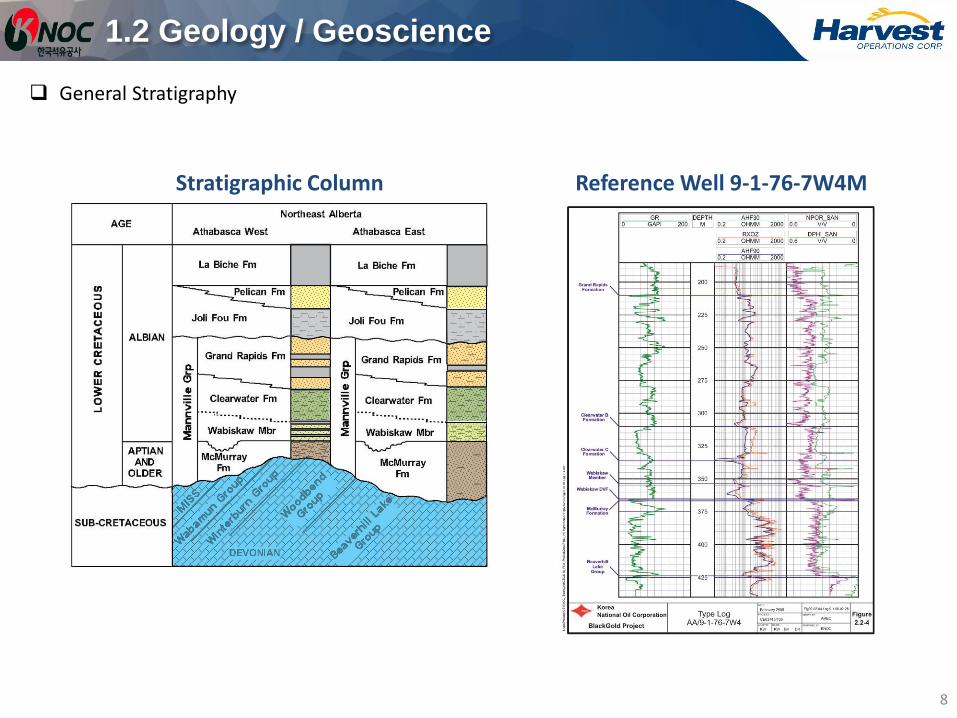
Stratigraphic Column Reference Well 9-1-76-7W4M
Figure 2: Regional stratigraphy for the Athabasca Oil Sands area.(After Wightman, 1995).
General Stratigraphy

1.2 Geology / Geoscience
Average Reservoir Properties:
– Reservoir Depth: 400mTVD (~205mSSL)
– McMurray Thickness: 45-55m
– Pay Thickness: 25-35m
– Porosity: 31%
– Perm: Khmedian=4D, Kv/Kh ~ 0.7
– Oil Saturation: 68%
– Virgin Reservoir Pressure: 2.6 MPa
– Virgin Reservoir Temp: 12⁰C
9

1.2 Geology / Geoscience
Original bitumen in place:
10
1.2 Geology / Geoscience
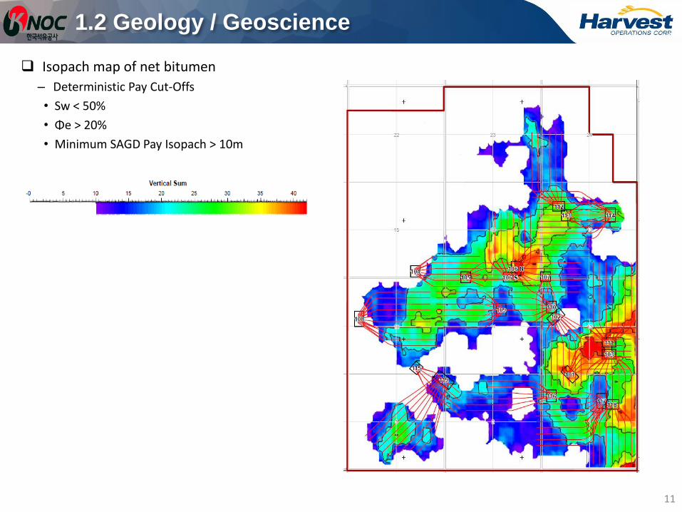
Isopach map of net bitumen
– Deterministic Pay Cut-Offs
• Sw < 50%
• Φe > 20%
• Minimum SAGD Pay Isopach > 10m
11

1.2 Geology / Geoscience
Structure map for top of bitumen pay
12
Subsea elevation (m)

1.2 Geology / Geoscience
Structure map for bottom of bitumen pay
13
Subsea elevation (m)

1.2 Geology / Geoscience
Representative composite well log: 1AA/02-12-076-07 W4/0
14
Top of BHL
Top of McMurray
Top of Wabiskaw
2-12 Net Bitumen Interval
McMurray Regional Barrier
Wabiskaw Regional Caprock
40
m

15
1.2 Geology / Geoscience
Blackgold McMurray Reservoir Caprock-Wabiskaw Regional Marine Shale
Wabiskaw Marine Shale Isopach Harvest Blackgold Project Contour interval = 0.5 m
(modified from July 2008)
Reference Well 1AA/02-12 (previous slide)
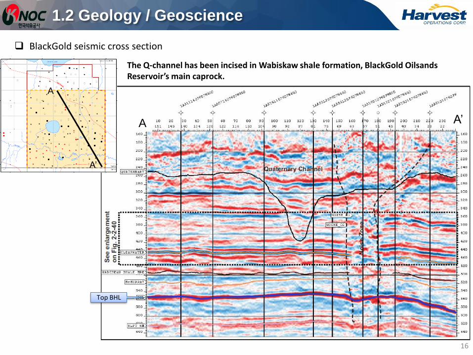
BlackGold seismic cross section
1.2 Geology / Geoscience
16
A
A’
A A’
Top BHL
The Q-channel has been incised in Wabiskaw shale formation, BlackGold Oilsands Reservoir’s main caprock.

17
Quaternary Channel Incision – BlackGold Project Area
1.2 Geology / Geoscience

1.2 Geology / Geoscience
Existing core logs and Formation Micro-Imager (FMI) logs
18
: Expansion area
: Initial area
: Initial Development Area
: Well with core (131 wells)
: Well with FMI Logs (24 wells)
Legend
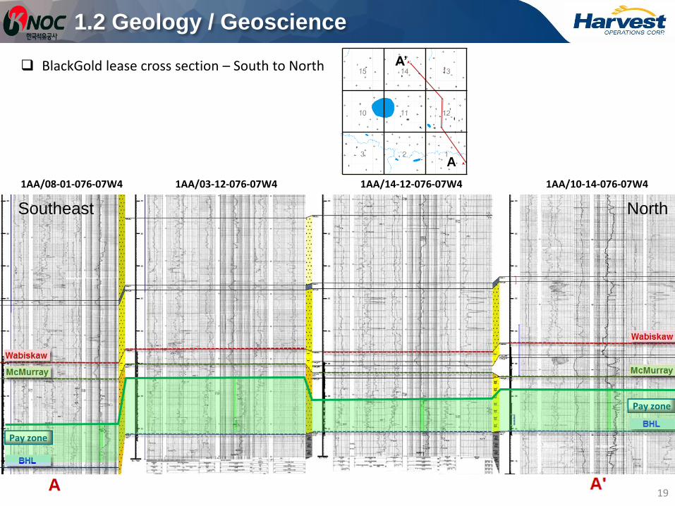
BlackGold lease cross section – South to North
1AA/08-01-076-07W4 1AA/03-12-076-07W4 1AA/14-12-076-07W4 1AA/10-14-076-07W4
Pay zone
Pay zone
Southeast North
A
A’
1.2 Geology / Geoscience
19
20
1.2 Geology / Geoscience
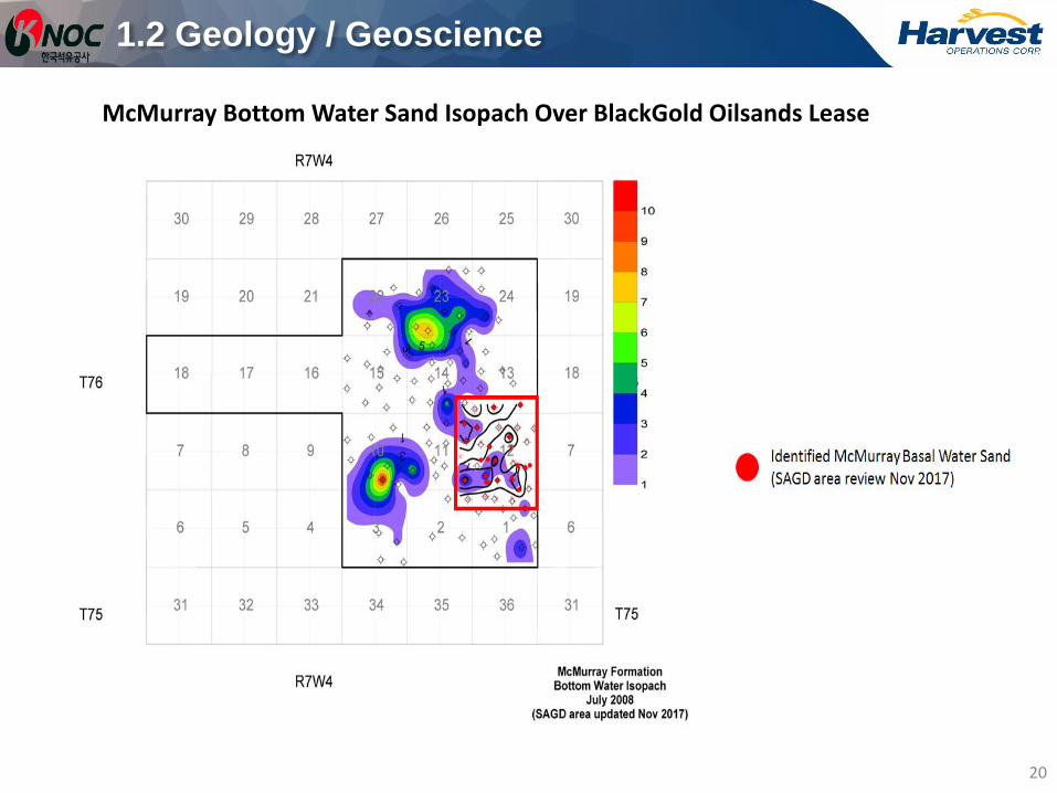
McMurray Bottom Water Sand Isopach Over BlackGold Oilsands Lease

21
1.2 Geology / Geoscience
McMurray Bottom Water Sand Isopach Over the SAGD Wellpair Area

22
1.2 Geology / Geoscience
SAGD Wellpair Elevations and the stand-off from McMurray Bottom Water Sand

2007 five corner reflectors have been installed.
2007 June to August SAR analyzed, no surface deformation observed.
2016 January, 32 additional corner reflectors were installed.
1.2 Geology / Geoscience
23

1.2 Geology / Geoscience
Reflector sites have been placed.
Satellite data will be collected and analyzed prior to first steam.
– Each reflector allows monitoring of approximately a 150 m radius
24

3D Seismic (23 km2)
1.2 Geology / Geoscience
25
3D seismic lines location map.
• Legend
Drilled before 2006 (52 wells)
Drilled 2007 (19 wells)
Drilled 2008 (32 wells)
Drilled 2009 (30 wells)
1.2 Geology / Geoscience
BlackGold geomechanical data and analyses
– Mini-fracture physical testing results obtained in 2008.
– The in-situ minimum stress in the McMurray shale is between 6.01 Mpa and 6.9 MPa (16.7 to 19.2 kPa/m).
– BlackGold geomechanical modeling confirmed that the McMurray cap rock integrity has a maximum down hole
pressure of 6 MPa.
– Approved maximum operating pressure is 5.5 MPa during steam circulation and 4 MPa during SAGD operations.
26

Agenda – 1. Subsurface
27
1.5 Instrumentation in Wells
1.2 Geology / Geoscience
1.3 Drilling and Completions
1.1 Background
1.4 Artificial Lift
1.6 4-D Seismic
1.7 Scheme Performance
1.8 Subsurface – Future Plans

3D Seismic (23 km2)
1.3 Drilling and Completions
28
Well pair trajectories.
• Legend
Drilled before 2006 (52 wells)
Drilled 2007 (19 wells)
Drilled 2008 (32 wells)
Drilled 2009 (30 wells)
Well Pair Trajectory

29
1.3 Drilling and Completions
All BlackGold SAGD well pairs are spaced about 95 - 100 meters except for 102-4, 102-5 and 102-6 which are spaced about 85 - 90 meters.

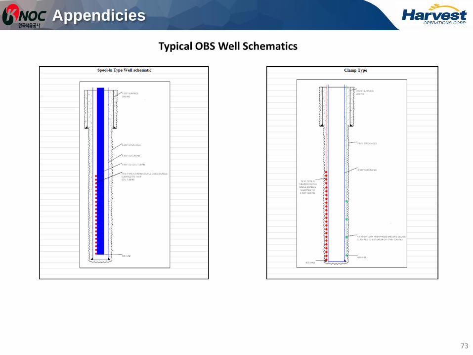
Harvest drilled 12 observation wells in 2011 to monitor performance
– 4 clamp type wells installed thermocouples and pressure gauge
– 8 spool in type wells installed thermocouples
30
: Pres./Temp. Sensor : Temp. Sensor Only
BHL/WOC
McMurray Reservoir
Wabiskaw/ McMurray
Shale
Thermocouples (2 ~4m interval)
Pressure Sensors
Thermal Cement
Overview of OBS Wells
Details of OBS well instrumentations are included in the appendices
1.3 Drilling and Completions

1.3 Drilling and Completions
Typical well bore schematic – Injector
31

1.3 Drilling and Completions
Typical well bore schematic – Producer during circulation
32

1.3 Drilling and Completions
Typical well bore schematic – Producer on SAGD production with ESP (Electric Submersible Pump)
33
1.3 Drilling and Completions
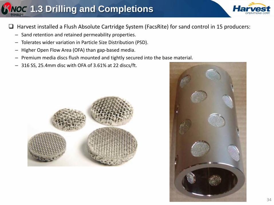
Harvest installed a Flush Absolute Cartridge System (FacsRite) for sand control in 15 producers:
– Sand retention and retained permeability properties.
– Tolerates wider variation in Particle Size Distribution (PSD).
– Higher Open Flow Area (OFA) than gap-based media.
– Premium media discs flush mounted and tightly secured into the base material.
– 316 SS, 25.4mm disc with OFA of 3.61% at 22 discs/ft.
34

Agenda – 1. Subsurface
35
1.5 Instrumentation in Wells
1.2 Geology / Geoscience
1.3 Drilling and Completions
1.1 Background
1.4 Artificial Lift
1.6 4-D Seismic
1.7 Scheme Performance
1.8 Subsurface – Future Plans

1.4 Artificial Lift
All producers will be equipped with ESPs (Electric Submersible Pumps) rated for 250OC.
All ESPs will have pressure/temperature monitoring systems.
ESP total fluid production capacity will vary between 300 to 730 m3/day.
36

Agenda – 1. Subsurface
37
1.5 Instrumentation in Wells
1.2 Geology / Geoscience
1.3 Drilling and Completions
1.1 Background
1.4 Artificial Lift
1.6 4-D Seismic
1.7 Scheme Performance
1.8 Subsurface – Future Plans

1.5 Instrumentation in Wells
Producers:
– 15 DTS fiber system during circulation and SAGD phase.
– 15 bubble tube to toe during circulation phase and 15 bubble tube to both toe and heel during SAGD phase.
Injectors:
– 8 DTS fiber system during circulation and SAGD phase.
– 8 bubble tube to toe during circulation and SAGD phase.
38
I & P with Instrumentation Producer with instrumentation

Agenda – 1. Subsurface
39
1.5 Instrumentation in Wells
1.2 Geology / Geoscience
1.3 Drilling and Completions
1.1 Background
1.4 Artificial Lift
1.6 4-D Seismic
1.7 Scheme Performance
1.8 Subsurface – Future Plans

1.6 4-D Seismic
Harvest acquired 4D seismic for initial development area in February 2012
40
4D Seismic Parameters
Area 4.26 km2
Bin size 10 m x 10 m
Shot interval 20 m
Shot line 80 m
Receiver interval
20 m
Receiver line 120 m
Record length 1,000 ms at 1/2 ms
Source type Single vibe, 8-200 Hz
linear@12,000 ms
Receiver type GS-30CT, 6 over 1 m
Geophone type 10-14 Hz spiked
geophone
Type of instrument
Telemetry 2.4km
1.8
km

Agenda – 1. Subsurface
41
1.5 Instrumentation in Wells
1.2 Geology / Geoscience
1.3 Drilling and Completions
1.1 Background
1.4 Artificial Lift
1.6 4-D Seismic
1.7 Scheme Performance
1.8 Subsurface – Future Plans

1.7 Scheme Performance
There is no scheme performance to report to date.
42

Agenda – 1. Subsurface
43
1.5 Instrumentation in Wells
1.2 Geology / Geoscience
1.3 Drilling and Completions
1.1 Background
1.4 Artificial Lift
1.6 4-D Seismic
1.7 Scheme Performance
1.8 Subsurface – Future Plans
1.8 Subsurface – Future Plans
Commissioning of wells and pads in Q2 2018.
First steam in Q2 2018.
ESP conversion in Q3 2018.
Harvest will acquire next a 4D survey in 2020.
44

Agenda – 2. Surface Operations
45
2.5 Water and Waste Disposal
2.2 MARP
2.3 Water Sources and Uses
2.1 Facilities
2.4 Water Treatment Technology
2.6 Sulphur Production
2.7 Environmental Issues & Compliance
2.8 Surface – Future Plans

2.1 Facilities
Modifications on Plot Plan
There have been no modifications to the Plot Plan since the last presentation.
Plant Construction
Construction substantially completed in Q1 2015.
Plant Performance
BlackGold is not operational as of Q4 2017.
46

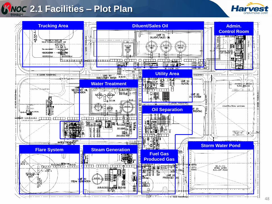
2.1 Facilities – Plot Plan
47
Nitrogen Package
2.1 Facilities – Plot Plan
48
Trucking Area Admin.
Control Room
Diluent/Sales Oil
Flare System
Water Treatment
Utility Area
Oil Separation
Fuel Gas
Produced Gas
Steam Generation Storm Water Pond

2.1 Facilities – 3D View
49

Agenda – 2. Surface Operations
50
2.5 Water and Waste Disposal
2.2 MARP
2.3 Water Sources and Uses
2.1 Facilities
2.4 Water Treatment Technology
2.6 Sulphur Production
2.7 Environmental Issues & Compliance
2.8 Surface – Future Plans

2.2 MARP
Update
The updated MARP was submitted and approved in 2017 in accordance with AER Directive 042 requirements.
Compliance with regulations
Meters will be calibrated annually once the well is in service.
Solvent and gas injection
No immediate plans to use solvent or gas co-injection.
51

2.2 MARP – Metering Schematic Diagram
344 Oil Battery – Production Metering
52

2.2 MARP – Metering Schematic Diagram
344 Oil Battery – Addition of a Coriolis meter and a Vortex meter to fuel gas supply line
53

2.2 MARP – Metering Schematic Diagram
506 Steam Injection Facility
54

2.2 MARP – Metering Schematic Diagram
902 Water Source Battery
55

Agenda – 2. Surface Operations
56
2.5 Water and Waste Disposal
2.2 MARP
2.3 Water Sources and Uses
2.1 Facilities
2.4 Water Treatment Technology
2.6 Sulphur Production
2.7 Environmental Issues & Compliance
2.8 Surface – Future Plans

2.3 Water Sources and Uses
Fresh Water Well
SW-14-076-07W4: Well test was completed and estimated to generate approximately 600 m3/d.
List of Brackish Water Wells
1F1/01-11-076-07W4/0 (Main Source well 802A)
1F1/07-11-076-07W4/0 (Main Source well 801A)
100/01-11-076-07W4/0 (Backup Well 802B)
100/07-11-076-07W4/0 (Backup Well 801B)
Volume of Saline Water
The volume of brackish/saline water required for steaming operations is about 608 m3/d for normal operation.
Saline Source Water Well Production Test commenced (Oct 2016)
The total volume of water produced was measured by flow meter installed in the well common header (801-FIT-0104 and 802-FIT-0104) and in CPF (80-FIT-0163) including flow totalizers.
57

2.3 Water Sources and Uses
1-11-76-7W4M & 7-11-76-7W4M
– Depth: 350 m to 353 m Total Vertical Depth (TVD)
– Formation: Clearwater
– Total Dissolved Solids (TDS): 4,320 to 4,550 mg/L
– Estimated production rate: 350 m3/day/well
58
7-11-76-7W4M Formation: Clearwater
TDS: 4,330 ppm
1-11-76-7W4M Formation: Clearwater
TDS: 4,550 ppm

2.3 Water Sources and Uses
59
Injection/Production
Wells
Brackish Water
Wells
7-11-76-7W4M
1-11-76-7W4M
Source Water
Pipeline Raw
Water
Tank
Utility Water Treatment
Package
Utility
Water
Tank
Produced
Water
Tank
Water Treatment
Package
Boiler Package
Pipeline CPF
Produced
Water
(4,291 m3/d)
Bitumen Emulsion
Steam
(4,770 m3/d)
Utility Water
(50 m3/d)
Safety Shower
10% Steam Loss
to the Formation
(477 m3/d)
Daily Make-up
Water
(608 m3/d) Make-up Water
to WT System
including Loss
from WT System
(558 m3/d)
Oil/Water Separation
Water in Sales
(8 m3/d)
System Loss (73 m3/d)

Agenda – 2. Surface Operations
60
2.5 Water and Waste Disposal
2.2 MARP
2.3 Water Sources and Uses
2.1 Facilities
2.4 Water Treatment Technology
2.6 Sulphur Production
2.7 Environmental Issues & Compliance
2.8 Surface – Future Plans

2.4 Water Treatment Technology
The installed, but not operational, water treatment technology is a high pH Mechanical Vapour Compression (MVC) evaporator with a crystallizer and solid forming equipment.
Evaporator Process
The feed water enters the steam stripping de-aerator, which has five stages of separation that lowers the dissolved oxygen level to less than 7 parts per billion.
The split-sump design minimizes energy consumption by evaporating roughly 70% of the total distillate flow in the first stage, or split.
The remaining 30% of the total distillate flow is produced in the second split under slightly more rigorous operating conditions. Combined distillate from two splits flows through a common distillate collection line.
61
2.4 Water Treatment Technology
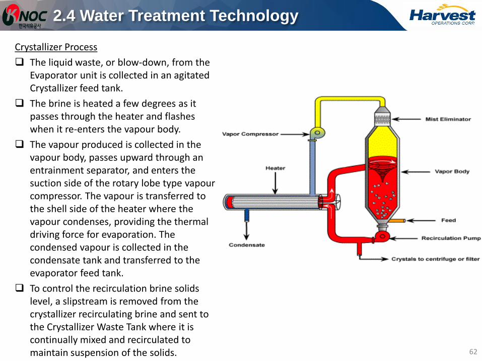
Crystallizer Process
The liquid waste, or blow-down, from the Evaporator unit is collected in an agitated Crystallizer feed tank.
The brine is heated a few degrees as it passes through the heater and flashes when it re-enters the vapour body.
The vapour produced is collected in the vapour body, passes upward through an entrainment separator, and enters the suction side of the rotary lobe type vapour compressor. The vapour is transferred to the shell side of the heater where the vapour condenses, providing the thermal driving force for evaporation. The condensed vapour is collected in the condensate tank and transferred to the evaporator feed tank.
To control the recirculation brine solids level, a slipstream is removed from the crystallizer recirculating brine and sent to the Crystallizer Waste Tank where it is continually mixed and recirculated to maintain suspension of the solids.
62

Agenda – 2. Surface Operations
63
2.5 Water and Waste Disposal
2.2 MARP
2.3 Water Sources and Uses
2.1 Facilities
2.4 Water Treatment Technology
2.6 Sulphur Production
2.7 Environmental Issues & Compliance
2.8 Surface – Future Plans

2.5 Water and Waste Disposal
No disposal wells are associated with this Scheme.
Waste disposal sites will be the appropriate class for solid and liquid process waste after operation begins.
64

Agenda – 2. Surface Operations
65
2.5 Water and Waste Disposal
2.2 MARP
2.3 Water Sources and Uses
2.1 Facilities
2.4 Water Treatment Technology
2.6 Sulphur Production
2.7 Environmental Issues & Compliance
2.8 Surface – Future Plans

2.6 Sulphur Production
As the CPF and wells were not in operation, no sulphur was produced at the BlackGold Facility.
66

Agenda – 2. Surface Operations
67
2.5 Water and Waste Disposal
2.2 MARP
2.3 Water Sources and Uses
2.1 Facilities
2.4 Water Treatment Technology
2.6 Sulphur Production
2.7 Environmental Issues & Compliance
2.8 Surface – Future Plans

2.7 Environmental Issues & Compliance
Harvest submitted the following plans in accordance with the EPEA Approval
Wetland and Waterbody Monitoring Program Proposal in 2014
– Authorized in December 2015.
– Variance request was authorized to commence monitoring during start-up.
– Amendment to the Program details was submitted in November 2016.
– Amendment was authorized in January of 2017.
Wildlife and Caribou Mitigation and Monitoring Programs
– Initiated the camera monitoring program in 2012.
– Observations of Moose, Wolves, Caribou, Sandhill Cranes, Owls.
– Amendments to the programs were approved in 2016.
– Track Surveys have been conducted.
– Bird and Amphibian Surveys have been conducted.
– Comprehensive Wildlife Report due September 2018.
Ground Water Monitoring Program
– Authorized in 2011.
– Amendments were authorized in 2015.
68

2.7 Environmental Issues & Compliance
Continuous Emissions Monitoring Program
– Program approved in 2017.
Air Monitoring Program
– Currently under review by the AER.
Project Level Conservation, Reclamation, and Closure Plan due October 31, 2017.
Annual C&R reports have been submitted for the years 2012 – 2016.
Amendment of Construction Deadline was authorized for September 2018.
Temporary Diversion Licence for water to create ice roads in 2015 for the installation of reflector sites for the InSar programs.
Authorization to store saline source water in the surface runoff pond during the winter and transfer it back to the pond in spring in 2016 and 2017.
Temporary Diversion Licence to transfer surface runoff water to the project tanks in preparation for commissioning activities and steam start-up in March of 2017.
Compliant with the Oil Sands Monitoring levy requirements.
Reclamation has not commenced.
69

2.7 Environmental Issues & Compliance
Self-disclosure to AER to notify of changes to licensed FG CO pipelines removing line segments which were not constructed.
Self-disclosure to AER of changes to pipeline licenses to change piping material to duplex stainless steel (31803) in place of carbon steel for produced gas pipeline.
Reported failure to submit Annual Groundwater Monitoring Report in 2015
– Continuous groundwater monitoring had not commenced at that time.
– Provided 7 day letter and Amendment request to vary annual reporting until project start-up.
Harvest is not aware of any compliance issues with regards to regulatory approval conditions related to the development of the BlackGold Project.
70

Agenda – 2. Surface Operations
71
2.5 Water and Waste Disposal
2.2 MARP
2.3 Water Sources and Uses
2.1 Facilities
2.4 Water Treatment Technology
2.6 Sulphur Production
2.7 Environmental Issues & Compliance
2.8 Surface – Future Plans

2.8 Surface – Future Plans
Application to amend Environment Protection and Enhancement Act Approval No. 246984-00-00 for Project Expansion is amended as 246984-00-02 December 5, 2013.
– Central Processing Facility Modifications.
– Well Pad Modifications.
BlackGold completion key dates and timelines:
– December 2017, construction resumes.
– Q2 2018, first steam generated.
– Q3 2018, Electric Submersible Pump (ESP) installations begin.
72
Appendicies
73
Typical OBS Well Schematics

Appendicies
74
OBS Well Instrumentation Information

Appendicies
75
OBS Well Instrumentation Information “Cont’d”

Appendicies
76
OBS Well Instrumentation Information “Cont’d”

Appendicies
77
OBS Well Instrumentation Information “Cont’d”

Appendicies
78
OBS Well Instrumentation Information “Cont’d”

Appendicies
79
OBS Well Instrumentation Information “Cont’d”