Embed Size (px)
Citation preview
5000 psi pressure gauge1/4" NPT malePart number: R978048671
Contents
Description. . . . . . . . . . . . . . . . . . . . . . . . . . . . . . . . . . . . . . . . . Page
Ordering code . . . . . . . . . . . . . . . . . . . . . . . . . . . . . . . . . . . . . . . 2
General information . . . . . . . . . . . . . . . . . . . . . . . . . . . . . . . . . . . 3
Standard models . . . . . . . . . . . . . . . . . . . . . . . . . . . . . . . . . . . . . 4
Bladder specifications . . . . . . . . . . . . . . . . . . . . . . . . . . . . . . . . . 5
Sizing calculations . . . . . . . . . . . . . . . . . . . . . . . . . . . . . . . . . . . . 6
Dimensional drawings . . . . . . . . . . . . . . . . . . . . . . . . . . . . . . . . . 9
Accessories . . . . . . . . . . . . . . . . . . . . . . . . . . . . . . . . . . . . . . . . 14
Installation & operation . . . . . . . . . . . . . . . . . . . . . . . . . . . . . . . 21
Safety notes & regulations . . . . . . . . . . . . . . . . . . . . . . . . . . . . 23
Spare Parts . . . . . . . . . . . . . . . . . . . . . . . . . . . . . . . . . . . . . . . . 24
Features
– Hydraulic accumulator according to ASME Section VIII pres-sure vessel code .
– Bladder material for different applications
Use:
– Energy storing in systems with intermittent operation
– Energy reserve for emergencies
– Compensation for leakage losses
– Impact and vibration damping
– Compensation of flow in the case of changes in pressure and temperature
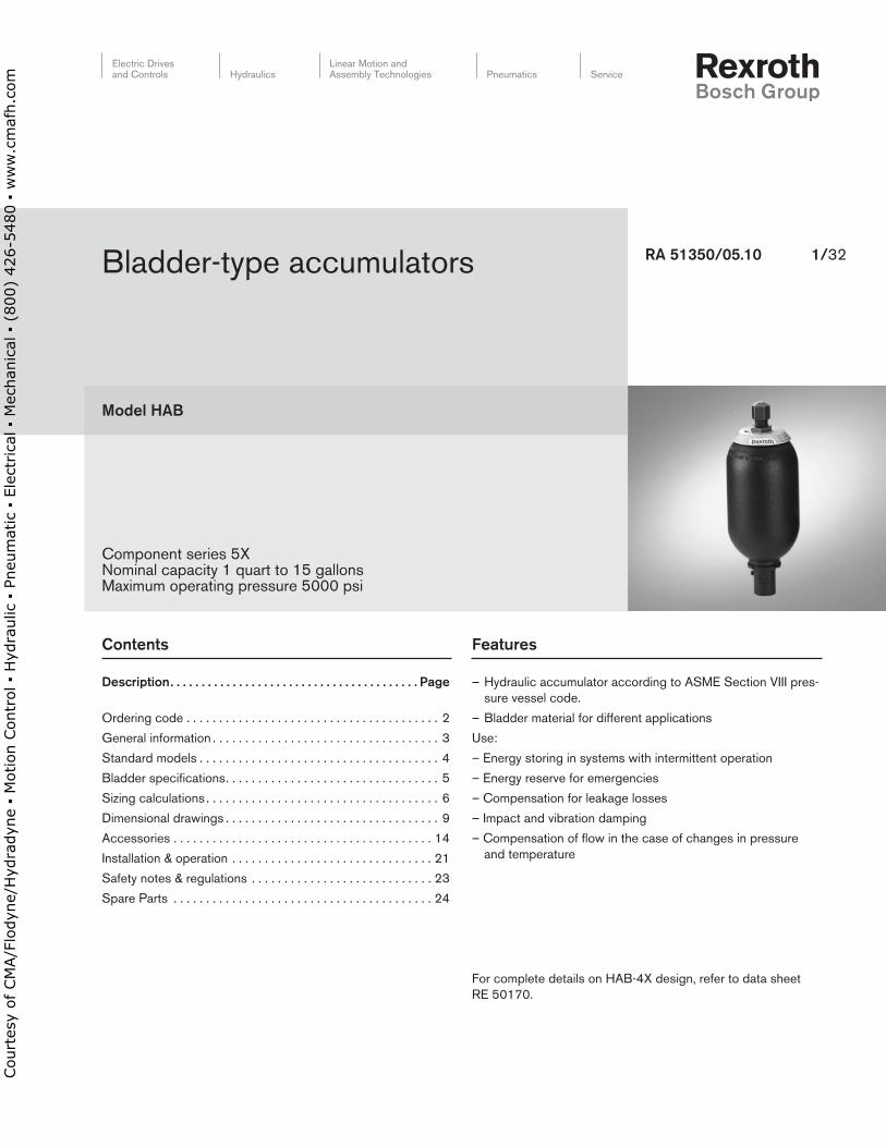
For complete details on HAB-4X design, refer to data sheet RE 50170 .
Model.HAB
RA.51350/05 .10. 1/32
Component series 5XNominal capacity 1 quart to 15 gallons Maximum operating pressure 5000 psi
Bladder-type accumulators
Electric Drives and Controls Hydraulics
Linear Motion and Assembly Technologies Pneumatics Service
Court
esy
of CM
A/F
lodyn
e/H
ydra
dyn
e ▪
Motion C
ontr
ol ▪
Hyd
raulic
▪ P
neu
mat
ic ▪
Ele
ctrica
l ▪
Mec
han
ical
▪ (
800)
426-5
480 ▪
ww
w.c
maf
h.c
om
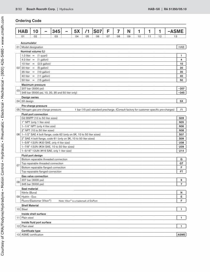
Accumulator01 Model designation HAB
Nominal.volume.(L)
02
1 .0 liter = (1 quart) 14 .0 liter = (1 gallon) 410 liter = (2 .5 gallon) 1020 liter = (5 gallon) 2035 liter = (10 gallon) 3540 liter = (11 gallon) 4050 liter = (15 gallon) 50
Maximum.pressure
03207 bar (3000 psi) –207345 bar (5000 psi, 10, 20, 35 and 50 liter only) –345
Design.series04 5X design 5X
Pre-charge.pressure05 Nitrogen gas pre-charge pressure 1 bar (15 psi) standard precharge . (Consult factory for customer specific pre-charges) /1
Fluid.port.connection
06
G2 BSPP (10 to 50 liter sizes) G091" NPT (only 1 liter size) N051–1/4" NPT (only 4 liter size) N062" NPT (10 to 50 liter sizes) N081–1/2" SAE 4 bolt flange, code 62 (only on 5K, 10 to 50 liter sizes) S072" SAE 4 bolt flange, code 61 (only on 3K, 10 to 50 liter sizes) S091–5/8"-12UN (#20 SAE, only 4 liter size) U081–7/8"-12UN (#24 SAE, 10 to 50 liter sizes) U091–5/16"-12UN (#16 SAE, only 1 liter size) U14
Fluid.port.design
07
Bottom repairable threaded connection GTop repairable threaded connection GTBottom repairable flanged connection FTop repairable flanged connection FT
Gas.valve.connection
08207 bar (3000 psi) 6345 bar (5000 psi) 7
Seal.material
09Nitrile (Buna) NHydrin - Eco EFluoro-Elastomer (Viton®) Note: Viton® is a trademark of DuPont F
Shell.Material10 Steel 1
Inside.shell.surface11 Plain steel 1
Inside.fluid.port.surface12 Plain steel 1
Certificate.type13 ASME certification ASME
HAB 10 – 345 – 5X /1 S07 F 7 N 1 1 1 –ASME01 02 03 04 05 06 07 08 09 10 11 12 13
Ordering.Code
2/32 Bosch.Rexroth.Corp . | .Hydraulics HAB–5X | RA.51350/05 .10
Court
esy
of CM
A/F
lodyn
e/H
ydra
dyn
e ▪
Motion C
ontr
ol ▪
Hyd
raulic
▪ P
neu
mat
ic ▪
Ele
ctrica
l ▪
Mec
han
ical
▪ (
800)
426-5
480 ▪
ww
w.c
maf
h.c
om
5
1
2
4
3
General.Information
1 ..Applications
Hydro-pneumatic accumulators can be used for the following functions:
1 . Store power for intermittent duty cycles thus economizing pump drive power .
2 . Provide energy or standby power
3 . Compensate for leakage loss
4 . Suspension in vehicles
5 . Dampen pulsations and shocks of a periodic nature .
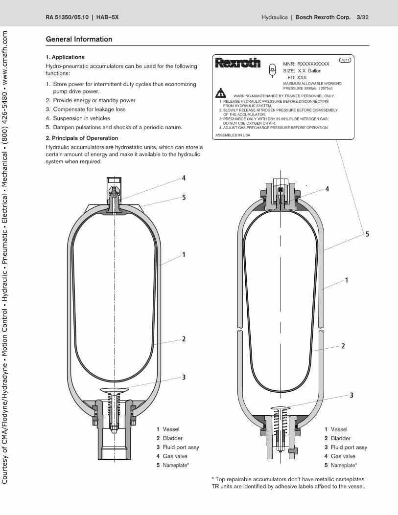
2 ..Principals.of.Opereration
Hydraulic accumulators are hydrostatic units, which can store a certain amount of energy and make it available to the hydraulic system when required .
1
2
3
4
5
1..Vessel
2 Bladder
3 Fluid port assy
4 Gas valve
5..Nameplate*
* Top repairable accumulators don't have metallic nameplates .TR units are identified by adhesive labels affixed to the vessel .
1..Vessel
2 Bladder
3 Fluid port assy
4 Gas valve
5..Nameplate*
RA.51350/05 .10..|..HAB–5X Hydraulics |..Bosch.Rexroth.Corp . 3/32
Court
esy
of CM
A/F
lodyn
e/H
ydra
dyn
e ▪
Motion C
ontr
ol ▪
Hyd
raulic
▪ P
neu
mat
ic ▪
Ele
ctrica
l ▪
Mec
han
ical
▪ (
800)
426-5
480 ▪
ww
w.c
maf
h.c
om
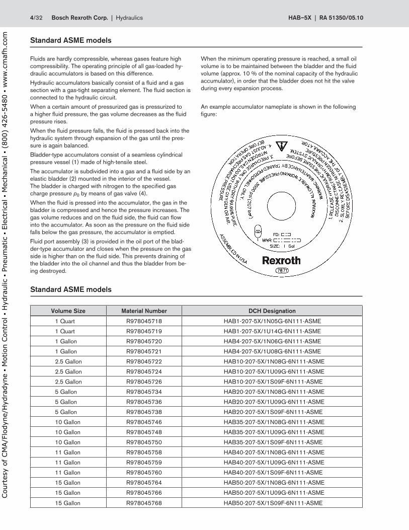
Standard.ASME.models
Volume.Size Material.Number DCH.Designation
1 Quart R978045718 HAB1-207-5X/1N05G-6N111-ASME
1 Quart R978045719 HAB1-207-5X/1U14G-6N111-ASME
1 Gallon R978045720 HAB4-207-5X/1N06G-6N111-ASME
1 Gallon R978045721 HAB4-207-5X/1U08G-6N111-ASME
2 .5 Gallon R978045722 HAB10-207-5X/1N08G-6N111-ASME
2 .5 Gallon R978045724 HAB10-207-5X/1U09G-6N111-ASME
2 .5 Gallon R978045726 HAB10-207-5X/1S09F-6N111-ASME
5 Gallon R978045734 HAB20-207-5X/1N08G-6N111-ASME
5 Gallon R978045736 HAB20-207-5X/1U09G-6N111-ASME
5 Gallon R978045738 HAB20-207-5X/1S09F-6N111-ASME
10 Gallon R978045746 HAB35-207-5X/1N08G-6N111-ASME
10 Gallon R978045748 HAB35-207-5X/1U09G-6N111-ASME
10 Gallon R978045750 HAB35-207-5X/1S09F-6N111-ASME
11 Gallon R978045758 HAB40-207-5X/1N08G-6N111-ASME
11 Gallon R978045759 HAB40-207-5X/1U09G-6N111-ASME
11 Gallon R978045760 HAB40-207-5X/1S09F-6N111-ASME
15 Gallon R978045764 HAB50-207-5X/1N08G-6N111-ASME
15 Gallon R978045766 HAB50-207-5X/1U09G-6N111-ASME
15 Gallon R978045768 HAB50-207-5X/1S09F-6N111-ASME
Standard.ASME.models
Fluids are hardly compressible, whereas gases feature high compressibility . The operating principle of all gas-loaded hy-draulic accumulators is based on this difference .
Hydraulic accumulators basically consist of a fluid and a gas section with a gas-tight separating element . The fluid section is connected to the hydraulic circuit .
When a certain amount of pressurized gas is pressurized to a higher fluid pressure, the gas volume decreases as the fluid pressure rises .
When the fluid pressure falls, the fluid is pressed back into the hydraulic system through expansion of the gas until the pres-sure is again balanced .
Bladder-type accumulators consist of a seamless cylindrical pressure vessel (1) made of high-tensile steel .
The accumulator is subdivided into a gas and a fluid side by an elastic bladder (2) mounted in the interior of the vessel . The bladder is charged with nitrogen to the specified gas charge pressure p0 by means of gas valve (4) .
When the fluid is pressed into the accumulator, the gas in the bladder is compressed and hence the pressure increases . The gas volume reduces and on the fluid side, the fluid can flow into the accumulator . As soon as the pressure on the fluid side falls below the gas pressure, the accumulator is emptied .
Fluid port assembly (3) is provided in the oil port of the blad-der-type accumulator and closes when the pressure on the gas side is higher than on the fluid side . This prevents draining of the bladder into the oil channel and thus the bladder from be-ing destroyed .
When the minimum operating pressure is reached, a small oil volume is to be maintained between the bladder and the fluid volume (approx . 10 % of the nominal capacity of the hydraulic accumulator), in order that the bladder does not hit the valve during every expansion process .
An example accumulator nameplate is shown in the following figure:
4/32 Bosch.Rexroth.Corp . | .Hydraulics HAB–5X | RA.51350/05 .10
Court
esy
of CM
A/F
lodyn
e/H
ydra
dyn
e ▪
Motion C
ontr
ol ▪
Hyd
raulic
▪ P
neu
mat
ic ▪
Ele
ctrica
l ▪
Mec
han
ical
▪ (
800)
426-5
480 ▪
ww
w.c
maf
h.c
om
Specifications
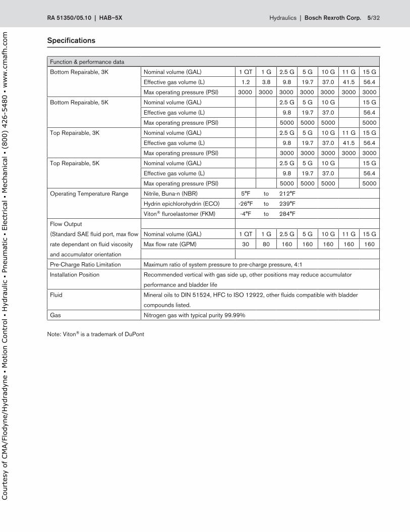
Function & performance data
Bottom Repairable, 3K Nominal volume (GAL) 1 QT 1 G 2 .5 G 5 G 10 G 11 G 15 G
Effective gas volume (L) 1 .2 3 .8 9 .8 19 .7 37 .0 41 .5 56 .4
Max operating pressure (PSI) 3000 3000 3000 3000 3000 3000 3000
Bottom Repairable, 5K Nominal volume (GAL) 2 .5 G 5 G 10 G 15 G
Effective gas volume (L) 9 .8 19 .7 37 .0 56 .4
Max operating pressure (PSI) 5000 5000 5000 5000
Top Repairable, 3K Nominal volume (GAL) 2 .5 G 5 G 10 G 11 G 15 G
Effective gas volume (L) 9 .8 19 .7 37 .0 41 .5 56 .4
Max operating pressure (PSI) 3000 3000 3000 3000 3000
Top Repairable, 5K Nominal volume (GAL) 2 .5 G 5 G 10 G 15 G
Effective gas volume (L) 9 .8 19 .7 37 .0 56 .4
Max operating pressure (PSI) 5000 5000 5000 5000
Operating Temperature Range Nitrile, Buna-n (NBR) 5°F to 212°F
Hydrin epichlorohydrin (ECO) -26°F to 239°F
Viton® fluroelastomer (FKM) -4°F to 284°F
Flow Output
(Standard SAE fluid port, max flow Nominal volume (GAL) 1 QT 1 G 2 .5 G 5 G 10 G 11 G 15 G
rate dependant on fluid viscosity Max flow rate (GPM) 30 80 160 160 160 160 160
and accumulator orientation
Pre-Charge Ratio Limitation Maximum ratio of system pressure to pre-charge pressure, 4:1
Installation Position Recommended vertical with gas side up, other positions may reduce accumulator
performance and bladder life
Fluid Mineral oils to DIN 51524, HFC to ISO 12922, other fluids compatible with bladder
compounds listed .
Gas Nitrogen gas with typical purity 99 .99%
Note: Viton® is a trademark of DuPont
RA.51350/05 .10..|..HAB–5X Hydraulics |..Bosch.Rexroth.Corp . 5/32
Court
esy
of CM
A/F
lodyn
e/H
ydra
dyn
e ▪
Motion C
ontr
ol ▪
Hyd
raulic
▪ P
neu
mat
ic ▪
Ele
ctrica
l ▪
Mec
han
ical
▪ (
800)
426-5
480 ▪
ww
w.c
maf
h.c
om
Sizing.calculations
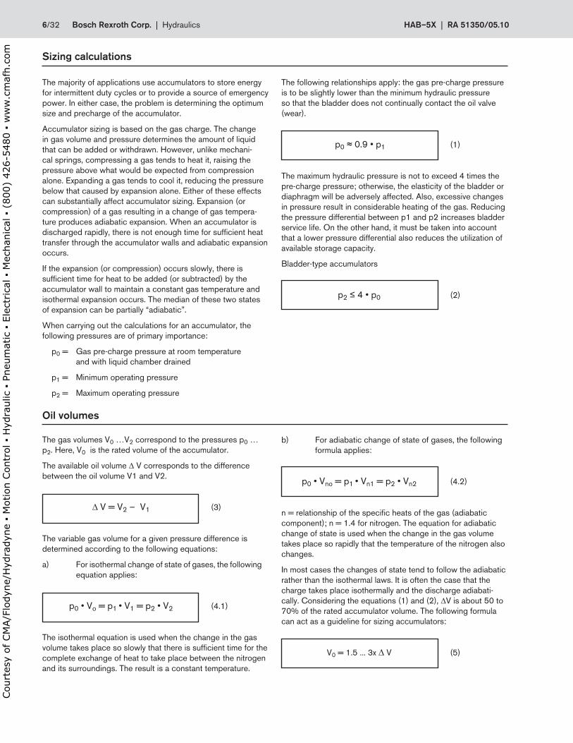
The majority of applications use accumulators to store energy for intermittent duty cycles or to provide a source of emergency power . In either case, the problem is determining the optimum size and precharge of the accumulator .
Accumulator sizing is based on the gas charge . The change in gas volume and pressure determines the amount of liquid that can be added or withdrawn . However, unlike mechani-cal springs, compressing a gas tends to heat it, raising the pressure above what would be expected from compression alone . Expanding a gas tends to cool it, reducing the pressure below that caused by expansion alone . Either of these effects can substantially affect accumulator sizing . Expansion (or compression) of a gas resulting in a change of gas tempera-ture produces adiabatic expansion . When an accumulator is discharged rapidly, there is not enough time for sufficient heat transfer through the accumulator walls and adiabatic expansion occurs .
If the expansion (or compression) occurs slowly, there is sufficient time for heat to be added (or subtracted) by the accumulator wall to maintain a constant gas temperature and isothermal expansion occurs . The median of these two states of expansion can be partially “adiabatic” .
When carrying out the calculations for an accumulator, the following pressures are of primary importance:
p0 = Gas pre-charge pressure at room temperature and with liquid chamber drained
p1 = Minimum operating pressure
p2 = Maximum operating pressure
The following relationships apply: the gas pre-charge pressure is to be slightly lower than the minimum hydraulic pressure so that the bladder does not continually contact the oil valve (wear) .
p0 ≈ 0 .9 • p1 (1)
The maximum hydraulic pressure is not to exceed 4 times the pre-charge pressure; otherwise, the elasticity of the bladder or diaphragm will be adversely affected . Also, excessive changes in pressure result in considerable heating of the gas . Reducing the pressure differential between p1 and p2 increases bladder service life . On the other hand, it must be taken into account that a lower pressure differential also reduces the utilization of available storage capacity .
Bladder-type accumulators
p2 ≤ 4 • p0 (2)
Oil.volumes
The gas volumes V0 …V2 correspond to the pressures p0 …p2 . Here, V0 is the rated volume of the accumulator .
The available oil volume ∆ V corresponds to the difference between the oil volume V1 and V2 .
∆ V = V2 – V1 (3)
The variable gas volume for a given pressure difference is determined according to the following equations:
a) For isothermal change of state of gases, the following equation applies:
p0 • Vo = p1 • V1 = p2 • V2 (4 .1)
The isothermal equation is used when the change in the gas volume takes place so slowly that there is sufficient time for the complete exchange of heat to take place between the nitrogen and its surroundings . The result is a constant temperature .
b) For adiabatic change of state of gases, the following formula applies:
p0 • Vno = p1 • Vn1 = p2 • Vn2 (4 .2)
n = relationship of the specific heats of the gas (adiabatic component); n = 1 .4 for nitrogen . The equation for adiabatic change of state is used when the change in the gas volume takes place so rapidly that the temperature of the nitrogen also changes .
In most cases the changes of state tend to follow the adiabatic rather than the isothermal laws . It is often the case that the charge takes place isothermally and the discharge adiabati-cally . Considering the equations (1) and (2), ∆V is about 50 to 70% of the rated accumulator volume . The following formula can act as a guideline for sizing accumulators:
V0 = 1 .5 . . . 3x ∆ V (5)
6/32 Bosch.Rexroth.Corp . | .Hydraulics HAB–5X | RA.51350/05 .10
Court
esy
of CM
A/F
lodyn
e/H
ydra
dyn
e ▪
Motion C
ontr
ol ▪
Hyd
raulic
▪ P
neu
mat
ic ▪
Ele
ctrica
l ▪
Mec
han
ical
▪ (
800)
426-5
480 ▪
ww
w.c
maf
h.c
om
Sizing.calculations
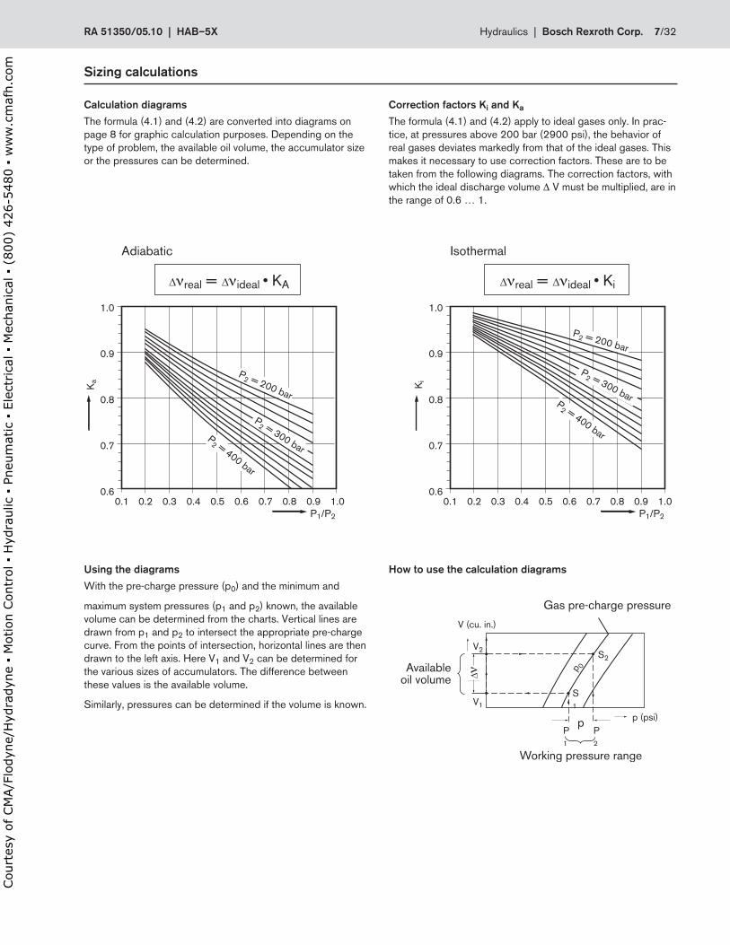
Calculation.diagrams
The formula (4 .1) and (4 .2) are converted into diagrams on page 8 for graphic calculation purposes . Depending on the type of problem, the available oil volume, the accumulator size or the pressures can be determined .
Correction.factors.Ki.and.Ka
The formula (4 .1) and (4 .2) apply to ideal gases only . In prac-tice, at pressures above 200 bar (2900 psi), the behavior of real gases deviates markedly from that of the ideal gases . This makes it necessary to use correction factors . These are to be taken from the following diagrams . The correction factors, with which the ideal discharge volume ∆ V must be multiplied, are in the range of 0 .6 … 1 .
1.0
0.9
0.8
0.7
0.60.1 0.2 0.3 0.4 0.5 0.6 0.7 0.8 0.9 1.0
P1/P2
Ki
P2 = 200 bar
P2 = 300 barP
2 = 400 bar
1.0
0.9
0.8
0.7
0.60.1 0.2 0.3 0.4 0.5 0.6 0.7 0.8 0.9 1.0
P1/P2
Ka
IsothermalAdiabatic
real = ideal • KA real = ideal • Ki
P2 = 200 bar
P2 = 300 bar
P2 = 400 bar
∆ ∆ ∆ ∆
Using.the.diagrams
With the pre-charge pressure (p0) and the minimum and
maximum system pressures (p1 and p2) known, the available volume can be determined from the charts . Vertical lines are drawn from p1 and p2 to intersect the appropriate pre-charge curve . From the points of intersection, horizontal lines are then drawn to the left axis . Here V1 and V2 can be determined for the various sizes of accumulators . The difference between these values is the available volume .
Similarly, pressures can be determined if the volume is known .
p 0
S2
S1
P1
P2
V2
V1
V (cu. in.)
p (psi)
Gas pre-charge pressure
Availableoil volume
Working pressure range
p
∆
How.to.use.the.calculation.diagrams
RA.51350/05 .10..|..HAB–5X Hydraulics |..Bosch.Rexroth.Corp . 7/32
Court
esy
of CM
A/F
lodyn
e/H
ydra
dyn
e ▪
Motion C
ontr
ol ▪
Hyd
raulic
▪ P
neu
mat
ic ▪
Ele
ctrica
l ▪
Mec
han
ical
▪ (
800)
426-5
480 ▪
ww
w.c
maf
h.c
om
Sizing.calculations
250250
100 5025
10
50150
45080015002250
2000
1750
1500
1250
1000
750
500
500
750
1000
1250
700
600
500
400
300
200100
150
200
250
300
350
400
125
100
75
50
40
30
20
14 10 5 2 1/2 1 1/4 20 6040 80 100
140
200
300
400
600
1000
1400
2000
20
3000
4000
5000
6000
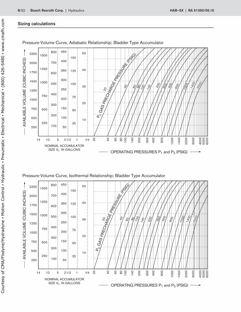
Pressure-Volume Curve, Adiabatic Relationship; Bladder Type Accumulator
40 60 80 100
140
300
400
600
1000
1400
2000
200
250250
100 5025
10
50150
45080015002250
2000
1750
1500
1250
1000
750
500
500
750
1000
1250
700
600
500
400
300
200100
150
200
250
300
350
400
125
100
75
50
40
30
20
14 10 5 2 1/2 1 1/4 20 6040 80 100
140
200
300
400
600
1000
1400
2000
20
3000
4000
5000
6000
Pressure-Volume Curve, Isothermal Relationship; Bladder Type Accumulator
40 60 80 100
140
300
400
600
1000
1400
2000
200
NOMINAL ACCUMULATORSIZE VO IN GALLONS
AVA
ILA
BLE
VO
LUM
E (C
UB
IC IN
CH
ES)
AVA
ILA
BLE
VO
LUM
E (C
UB
IC IN
CH
ES)
OPERATING PRESSURES P1 and P2 (PSIG)
NOMINAL ACCUMULATORSIZE VO IN GALLONS
OPERATING PRESSURES P1 and P2 (PSIG)
P 0 G
AS
PR
ECH
ARG
E PR
ESSU
RE (P
SIG
)
P 0 G
AS P
REC
HAR
GE
PRES
SURE
(PSIG
)
8/32 Bosch.Rexroth.Corp . | .Hydraulics HAB–5X | RA.51350/05 .10
Court
esy
of CM
A/F
lodyn
e/H
ydra
dyn
e ▪
Motion C
ontr
ol ▪
Hyd
raulic
▪ P
neu
mat
ic ▪
Ele
ctrica
l ▪
Mec
han
ical
▪ (
800)
426-5
480 ▪
ww
w.c
maf
h.c
om
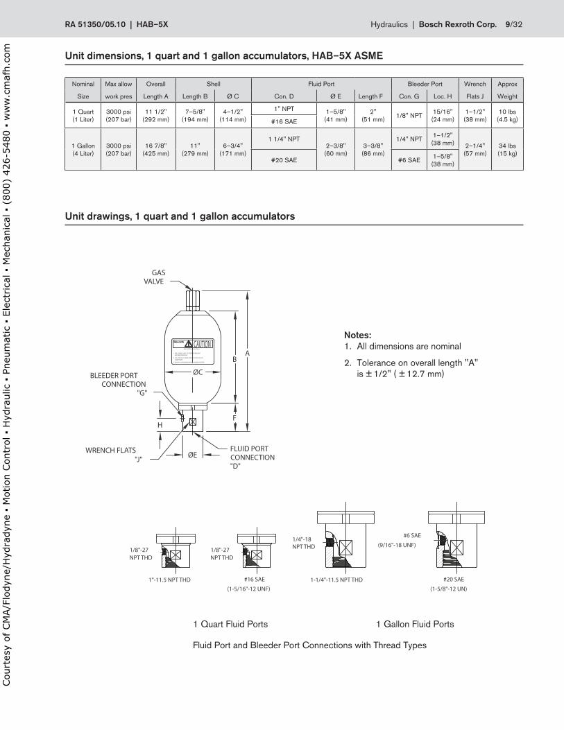
Unit.dimensions,.1.quart.and.1.gallon.accumulators,.HAB–5X.ASME
Nominal Max allow Overall Shell Fluid Port Bleeder Port Wrench Approx
Size work pres Length A Length B Ø C Con . D Ø E Length F Con . G Loc . H Flats J Weight
1 Quart(1 Liter)
3000 psi(207 bar)
11 1/2"(292 mm)
7–5/8" (194 mm)
4–1/2"(114 mm)
1" NPT 1–5/8"(41 mm)
2"(51 mm) 1/8" NPT 15/16"
(24 mm)1–1/2"
(38 mm)10 lbs
(4 .5 kg)#16 SAE
1 Gallon(4 Liter)
3000 psi(207 bar)
16 7/8"(425 mm)
11"(279 mm)
6–3/4"(171 mm)
1 1/4" NPT2–3/8"
(60 mm)3–3/8"
(86 mm)
1/4" NPT 1–1/2"(38 mm) 2–1/4"
(57 mm)34 lbs(15 kg)
#20 SAE #6 SAE 1–5/8"(38 mm)
GASVALVE
BLEEDER PORTCONNECTION
"G"
FLUID PORTCONNECTION"D"
ØE
ØC
H
A
F
B
CAUTIONUSE NITROGEN GAS ONLY
1. PRE-CHARGE UNIT TO DESIRED PRESSUREBEFORE OPERATING.
2. FOLLOW PRE-CHARGE INSTRUCTIONS ON THENAMEPLATE.
3. DO NOT DISASSEMBLE WHILE UNDER PRESSURE.
#20 SAE
(1-5/8"-12 UN)1-1/4"-11.5 NPT THD
1/4"-18(9/16"-18 UNF)
#6 SAE
1"-11.5 NPT THD(1-5/16"-12 UNF)
#16 SAE
1/8"-27NPT THD
NPT THD1/8"-27NPT THD
"J"WRENCH FLATS
Fluid Port and Bleeder Port Connections with Thread Types
1 Quart Fluid Ports 1 Gallon Fluid Ports
Notes:1 . All dimensions are nominal
2 . Tolerance on overall length "A" is ± 1/2" ( ± 12 .7 mm)
Unit.drawings,.1.quart.and.1.gallon.accumulators
GASVALVE
BLEEDER PORTCONNECTION
"G"
FLUID PORTCONNECTION"D"
ØE
ØC
H
A
F
B
CAUTIONUSE NITROGEN GAS ONLY
1. PRE-CHARGE UNIT TO DESIRED PRESSUREBEFORE OPERATING.
2. FOLLOW PRE-CHARGE INSTRUCTIONS ON THENAMEPLATE.
3. DO NOT DISASSEMBLE WHILE UNDER PRESSURE.
#20 SAE
(1-5/8"-12 UN)1-1/4"-11.5 NPT THD
1/4"-18(9/16"-18 UNF)
#6 SAE
1"-11.5 NPT THD(1-5/16"-12 UNF)
#16 SAE
1/8"-27NPT THD
NPT THD1/8"-27NPT THD
"J"WRENCH FLATS
RA.51350/05 .10..|..HAB–5X Hydraulics |..Bosch.Rexroth.Corp . 9/32
Court
esy
of CM
A/F
lodyn
e/H
ydra
dyn
e ▪
Motion C
ontr
ol ▪
Hyd
raulic
▪ P
neu
mat
ic ▪
Ele
ctrica
l ▪
Mec
han
ical
▪ (
800)
426-5
480 ▪
ww
w.c
maf
h.c
om
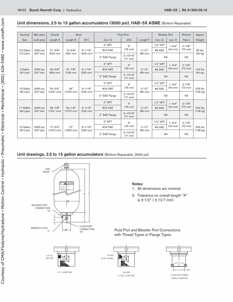
Unit.dimensions,.2 .5.to.15.gallon.accumulators.(3000.psi),.HAB–5X.ASME (Bottom Repairable)
Nominal Max allow Overall Shell Fluid Port Bleeder Port Wrench Approx
Size work pres Length A Length B Ø C Con . D Ø E Length F Con . G Loc . H Flats J Weight
2 .5 Gallon(10 Liter)
3000 psi(207 bar)
21–3/8"(543 mm)
15–5/8" (397 mm)
9–1/16"(230 mm)
2" NPT 3"(76 mm) 3 1/2"
(89 mm)
1/4" NPT 1–3/4"(44 mm)
2–7/8"(73 mm) 80 lbs
(36 kg)#24 SAE #6 SAE
2" SAE Flange 2–13/16"(71 mm) NA NA
5 Gallon(20 Liter)
3000 psi(207 bar)
33–5/8"(854 mm)
27–7/8" (708 mm)
9–1/16"(230 mm)
2" NPT 3"(76 mm) 3 1/2"
(89 mm)
1/4" NPT 1–3/4"(44 mm)
2–7/8"(73 mm) 120 lbs
(54 kg)#24 SAE #6 SAE
2" SAE Flange 2–13/16"(71 mm) NA NA
10 Gallon(35 Liter)
3000 psi(207 bar)
54–3/4"(1391 mm)
49" (1245 mm)
9–1/16"(230 mm)
2" NPT 3"(76 mm) 3 1/2"
(89 mm)
1/4" NPT 1–3/4"(44 mm)
2–7/8"(73 mm) 220 lbs
(100 kg)#24 SAE #6 SAE
2" SAE Flange 2–13/16"(71 mm) NA NA
11 Gallon(40 Liter)
3000 psi(207 bar)
59–7/8"(1521 mm)
54–1/8" (1375 mm)
9–1/16"(230 mm)
2" NPT 3"(76 mm) 3 1/2"
(89 mm)
1/4" NPT 1–3/4"(44 mm)
2–7/8"(73 mm) 240 lbs
(109 kg)#24 SAE #6 SAE
2" SAE Flange 2–13/16"(71 mm) NA NA
15 Gallon(50 Liter)
3000 psi(207 bar)
77–3/4"(1975 mm)
72" (1829 mm)
9–1/16"(230 mm)
2" NPT 3"(76 mm) 3 1/2"
(89 mm)
1/4" NPT 1–3/4"(44 mm)
2–7/8"(73 mm) 305 lbs
(138 kg)#24 SAE #6 SAE
2" SAE Flange 2–13/16"(71 mm) NA NA
Unit.drawings,.2 .5.to.15.gallon.accumulators.(Bottom Repairable, 3000 psi)
GASVALVE
BLEEDER PORTCONNECTION
"G"
FLUID PORTCONNECTION"D"
ØE
ØC
H
A
F
B
CAUTIONUSE NITROGEN GAS ONLY
1. PRE-CHARGE UNIT TO DESIRED PRESSUREBEFORE OPERATING.
2. FOLLOW PRE-CHARGE INSTRUCTIONS ON THENAMEPLATE.
3. DO NOT DISASSEMBLE WHILE UNDER PRESSURE.
Ø2"
1/4"-18
2"-11.5 NPT THD
(9/16"-18 UNF)
#6 SAE
#24 SAE
(1-7/8"-12 UN THD) 2" SAE SPLIT FLANGE
CODE 61 (3000 PSI)
NPT THD
WRENCH FLATS"J" Fluid Port and Bleeder Port Connections
with Thread Types or Flange Types
Notes:1 . All dimensions are nominal
2 . Tolerance on overall length "A" is ± 1/2" ( ± 12 .7 mm)
10/32 Bosch.Rexroth.Corp . | .Hydraulics HAB–5X | RA.51350/05 .10
Court
esy
of CM
A/F
lodyn
e/H
ydra
dyn
e ▪
Motion C
ontr
ol ▪
Hyd
raulic
▪ P
neu
mat
ic ▪
Ele
ctrica
l ▪
Mec
han
ical
▪ (
800)
426-5
480 ▪
ww
w.c
maf
h.c
om
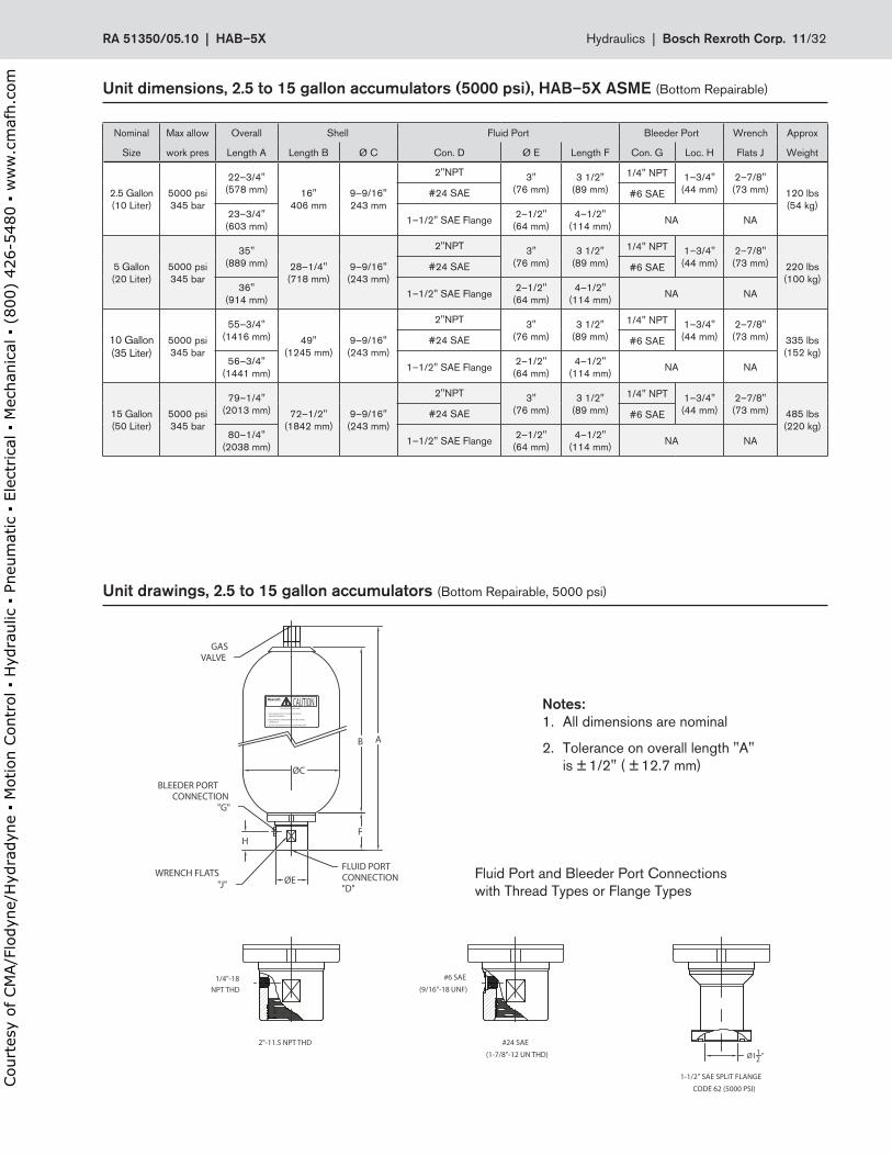
Nominal Max allow Overall Shell Fluid Port Bleeder Port Wrench Approx
Size work pres Length A Length B Ø C Con . D Ø E Length F Con . G Loc . H Flats J Weight
2 .5 Gallon(10 Liter)
5000 psi345 bar
22–3/4"(578 mm) 16"
406 mm9–9/16"243 mm
2"NPT 3"(76 mm)
3 1/2"(89 mm)
1/4" NPT 1–3/4"(44 mm)
2–7/8"(73 mm) 120 lbs
(54 kg)#24 SAE #6 SAE
23–3/4"(603 mm) 1–1/2" SAE Flange 2–1/2"
(64 mm)4–1/2"
(114 mm) NA NA
5 Gallon(20 Liter)
5000 psi345 bar
35"(889 mm) 28–1/4"
(718 mm)9–9/16"
(243 mm)
2"NPT 3"(76 mm)
3 1/2"(89 mm)
1/4" NPT 1–3/4"(44 mm)
2–7/8"(73 mm) 220 lbs
(100 kg)#24 SAE #6 SAE
36"(914 mm) 1–1/2" SAE Flange 2–1/2"
(64 mm)4–1/2"
(114 mm) NA NA
10 Gallon(35 Liter)
5000 psi345 bar
55–3/4"(1416 mm) 49"
(1245 mm)9–9/16"
(243 mm)
2"NPT 3"(76 mm)
3 1/2"(89 mm)
1/4" NPT 1–3/4"(44 mm)
2–7/8"(73 mm) 335 lbs
(152 kg)#24 SAE #6 SAE
56–3/4"(1441 mm) 1–1/2" SAE Flange 2–1/2"
(64 mm)4–1/2"
(114 mm) NA NA
15 Gallon(50 Liter)
5000 psi345 bar
79–1/4"(2013 mm) 72–1/2"
(1842 mm)9–9/16"
(243 mm)
2"NPT 3"(76 mm)
3 1/2"(89 mm)
1/4" NPT 1–3/4"(44 mm)
2–7/8"(73 mm) 485 lbs
(220 kg)#24 SAE #6 SAE
80–1/4"(2038 mm) 1–1/2" SAE Flange 2–1/2"
(64 mm)4–1/2"
(114 mm) NA NA
Unit.dimensions,.2 .5.to.15.gallon.accumulators.(5000.psi),.HAB–5X.ASME (Bottom Repairable)
Unit.drawings,.2 .5.to.15.gallon.accumulators.(Bottom Repairable, 5000 psi)
GASVALVE
BLEEDER PORTCONNECTION
"G"
FLUID PORTCONNECTION"D"
ØE
ØC
H
A
F
B
CAUTIONUSE NITROGEN GAS ONLY
1. PRE-CHARGE UNIT TO DESIRED PRESSUREBEFORE OPERATING.
2. FOLLOW PRE-CHARGE INSTRUCTIONS ON THENAMEPLATE.
3. DO NOT DISASSEMBLE WHILE UNDER PRESSURE.
Ø112 "
1/4"-18
2"-11.5 NPT THD
(9/16"-18 UNF)
#6 SAE
#24 SAE
(1-7/8"-12 UN THD)
CODE 62 (5000 PSI)
1-1/2" SAE SPLIT FLANGE
NPT THD
WRENCH FLATS"J"
Fluid Port and Bleeder Port Connections with Thread Types or Flange Types
Notes:1 . All dimensions are nominal
2 . Tolerance on overall length "A" is ± 1/2" ( ± 12 .7 mm)
RA.51350/05 .10..|..HAB–5X Hydraulics |..Bosch.Rexroth.Corp . 11/32
Court
esy
of CM
A/F
lodyn
e/H
ydra
dyn
e ▪
Motion C
ontr
ol ▪
Hyd
raulic
▪ P
neu
mat
ic ▪
Ele
ctrica
l ▪
Mec
han
ical
▪ (
800)
426-5
480 ▪
ww
w.c
maf
h.c
om
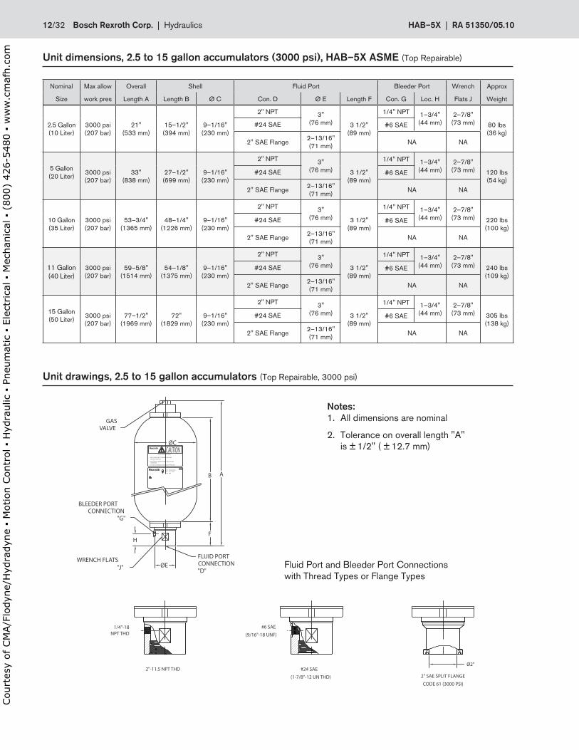
Nominal Max allow Overall Shell Fluid Port Bleeder Port Wrench Approx
Size work pres Length A Length B Ø C Con . D Ø E Length F Con . G Loc . H Flats J Weight
2 .5 Gallon(10 Liter)
3000 psi(207 bar)
21"(533 mm)
15–1/2" (394 mm)
9–1/16"(230 mm)
2" NPT 3"(76 mm) 3 1/2"
(89 mm)
1/4" NPT 1–3/4"(44 mm)
2–7/8"(73 mm) 80 lbs
(36 kg)#24 SAE #6 SAE
2" SAE Flange 2–13/16"(71 mm) NA NA
5 Gallon(20 Liter)
3000 psi(207 bar)
33"(838 mm)
27–1/2" (699 mm)
9–1/16"(230 mm)
2" NPT 3"(76 mm) 3 1/2"
(89 mm)
1/4" NPT 1–3/4"(44 mm)
2–7/8"(73 mm) 120 lbs
(54 kg)#24 SAE #6 SAE
2" SAE Flange 2–13/16"(71 mm) NA NA
10 Gallon(35 Liter)
3000 psi(207 bar)
53–3/4"(1365 mm)
48–1/4" (1226 mm)
9–1/16"(230 mm)
2" NPT 3"(76 mm) 3 1/2"
(89 mm)
1/4" NPT 1–3/4"(44 mm)
2–7/8"(73 mm) 220 lbs
(100 kg)#24 SAE #6 SAE
2" SAE Flange 2–13/16"(71 mm) NA NA
11 Gallon(40 Liter)
3000 psi(207 bar)
59–5/8"(1514 mm)
54–1/8" (1375 mm)
9–1/16"(230 mm)
2" NPT 3"(76 mm) 3 1/2"
(89 mm)
1/4" NPT 1–3/4"(44 mm)
2–7/8"(73 mm) 240 lbs
(109 kg)#24 SAE #6 SAE
2" SAE Flange 2–13/16"(71 mm) NA NA
15 Gallon(50 Liter)
3000 psi(207 bar)
77–1/2"(1969 mm)
72" (1829 mm)
9–1/16"(230 mm)
2" NPT 3"(76 mm) 3 1/2"
(89 mm)
1/4" NPT 1–3/4"(44 mm)
2–7/8"(73 mm) 305 lbs
(138 kg)#24 SAE #6 SAE
2" SAE Flange 2–13/16"(71 mm) NA NA
Unit.dimensions,.2 .5.to.15.gallon.accumulators.(3000.psi),.HAB–5X.ASME (Top Repairable)
Unit.drawings,.2 .5.to.15.gallon.accumulators (Top Repairable, 3000 psi)
GASVALVE
BLEEDER PORTCONNECTION
"G"
FLUID PORTCONNECTION"D"
ØE
ØC
H
A
F
B
3. DO NOT DISASSEMBLE WHILE UNDER PRESSURE.
NAMEPLATE.2. FOLLOW PRE-CHARGE INSTRUCTIONS ON THE
BEFORE OPERATING.1. PRE-CHARGE UNIT TO DESIRED PRESSURE
USE NITROGEN GAS ONLY
CAUTION
MNR:SIZE:
FD:Gallon
RXXXXXXXXXX.XXXX
NPT THD
CODE 61 (3000 PSI)
2" SAE SPLIT FLANGE(1-7/8"-12 UN THD)
#24 SAE
#6 SAE
(9/16"-18 UNF)
2"-11.5 NPT THD
1/4"-18
Ø2"
"J"WRENCH FLATS
Fluid Port and Bleeder Port Connections with Thread Types or Flange Types
Notes:1 . All dimensions are nominal
2 . Tolerance on overall length "A" is ± 1/2" ( ± 12 .7 mm)
12/32 Bosch.Rexroth.Corp . | .Hydraulics HAB–5X | RA.51350/05 .10
Court
esy
of CM
A/F
lodyn
e/H
ydra
dyn
e ▪
Motion C
ontr
ol ▪
Hyd
raulic
▪ P
neu
mat
ic ▪
Ele
ctrica
l ▪
Mec
han
ical
▪ (
800)
426-5
480 ▪
ww
w.c
maf
h.c
om
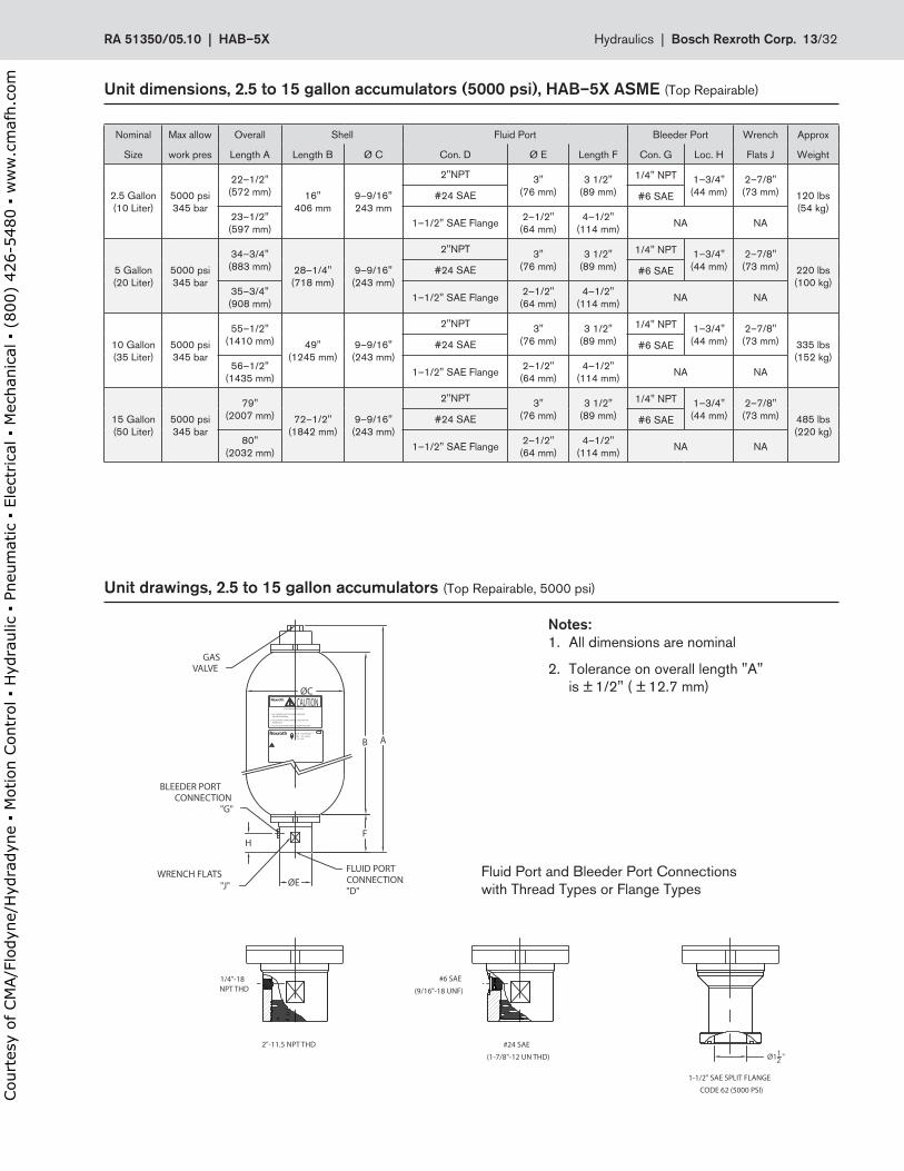
Nominal Max allow Overall Shell Fluid Port Bleeder Port Wrench Approx
Size work pres Length A Length B Ø C Con . D Ø E Length F Con . G Loc . H Flats J Weight
2 .5 Gallon(10 Liter)
5000 psi345 bar
22–1/2"(572 mm) 16"
406 mm9–9/16"243 mm
2"NPT 3"(76 mm)
3 1/2"(89 mm)
1/4" NPT 1–3/4"(44 mm)
2–7/8"(73 mm) 120 lbs
(54 kg)#24 SAE #6 SAE
23–1/2"(597 mm) 1–1/2" SAE Flange 2–1/2"
(64 mm)4–1/2"
(114 mm) NA NA
5 Gallon(20 Liter)
5000 psi345 bar
34–3/4"(883 mm) 28–1/4"
(718 mm)9–9/16"
(243 mm)
2"NPT 3"(76 mm)
3 1/2"(89 mm)
1/4" NPT 1–3/4"(44 mm)
2–7/8"(73 mm) 220 lbs
(100 kg)#24 SAE #6 SAE
35–3/4"(908 mm) 1–1/2" SAE Flange 2–1/2"
(64 mm)4–1/2"
(114 mm) NA NA
10 Gallon(35 Liter)
5000 psi345 bar
55–1/2"(1410 mm) 49"
(1245 mm)9–9/16"
(243 mm)
2"NPT 3"(76 mm)
3 1/2"(89 mm)
1/4" NPT 1–3/4"(44 mm)
2–7/8"(73 mm) 335 lbs
(152 kg)#24 SAE #6 SAE
56–1/2"(1435 mm) 1–1/2" SAE Flange 2–1/2"
(64 mm)4–1/2"
(114 mm) NA NA
15 Gallon(50 Liter)
5000 psi345 bar
79"(2007 mm) 72–1/2"
(1842 mm)9–9/16"
(243 mm)
2"NPT 3"(76 mm)
3 1/2"(89 mm)
1/4" NPT 1–3/4"(44 mm)
2–7/8"(73 mm) 485 lbs
(220 kg)#24 SAE #6 SAE
80"(2032 mm) 1–1/2" SAE Flange 2–1/2"
(64 mm)4–1/2"
(114 mm) NA NA
Unit.dimensions,.2 .5.to.15.gallon.accumulators.(5000.psi),.HAB–5X.ASME (Top Repairable)
Unit.drawings,.2 .5.to.15.gallon.accumulators (Top Repairable, 5000 psi)
GASVALVE
BLEEDER PORTCONNECTION
"G"
FLUID PORTCONNECTION"D"
ØE
ØC
H
A
F
B
3. DO NOT DISASSEMBLE WHILE UNDER PRESSURE.
NAMEPLATE.2. FOLLOW PRE-CHARGE INSTRUCTIONS ON THE
BEFORE OPERATING.1. PRE-CHARGE UNIT TO DESIRED PRESSURE
USE NITROGEN GAS ONLY
CAUTION
MNR:SIZE:
FD:Gallon
RXXXXXXXXXX.XXXX
NPT THD
1-1/2" SAE SPLIT FLANGE
CODE 62 (5000 PSI)
(1-7/8"-12 UN THD)
#24 SAE
#6 SAE
(9/16"-18 UNF)
2"-11.5 NPT THD
1/4"-18
Ø112 "
"J"WRENCH FLATS Fluid Port and Bleeder Port Connections
with Thread Types or Flange Types
Notes:1 . All dimensions are nominal
2 . Tolerance on overall length "A" is ± 1/2" ( ± 12 .7 mm)
RA.51350/05 .10..|..HAB–5X Hydraulics |..Bosch.Rexroth.Corp . 13/32
Court
esy
of CM
A/F
lodyn
e/H
ydra
dyn
e ▪
Motion C
ontr
ol ▪
Hyd
raulic
▪ P
neu
mat
ic ▪
Ele
ctrica
l ▪
Mec
han
ical
▪ (
800)
426-5
480 ▪
ww
w.c
maf
h.c
om
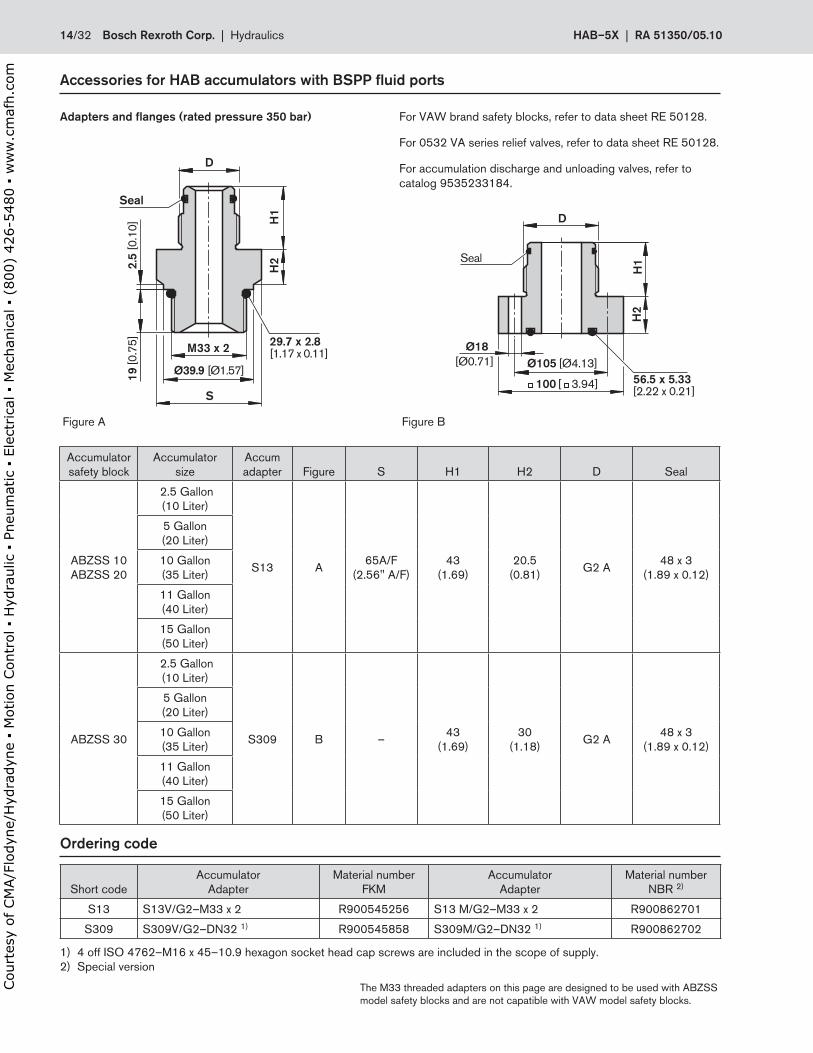
Accessories.for.HAB.accumulators.with.BSPP.fluid.ports
Adapters.and.flanges.(rated.pressure.350.bar)
Accumulatorsafety block
Accumulatorsize
Accumadapter Figure S H1 H2 D Seal
ABZSS 10ABZSS 20
2 .5 Gallon(10 Liter)
S13 A 65A/F(2 .56" A/F)
43(1 .69)
20 .5(0 .81) G2 A 48 x 3
(1 .89 x 0 .12)
5 Gallon(20 Liter)
10 Gallon(35 Liter)
11 Gallon(40 Liter)
15 Gallon(50 Liter)
ABZSS 30
2 .5 Gallon(10 Liter)
S309 B – 43(1 .69)
30(1 .18) G2 A 48 x 3
(1 .89 x 0 .12)
5 Gallon(20 Liter)
10 Gallon(35 Liter)
11 Gallon(40 Liter)
15 Gallon(50 Liter)
Figure A Figure B
D
S
M33 x 2
19 [0
.75]
2.5
[0.1
0]
H2
H1
29.7 x 2.8[1.17 x 0.11]
Seal
Ø39.9 [Ø1.57]
D
Ø105 [Ø4.13]
100 [ 3.94]
Ø18[Ø0.71]
56.5 x 5.33[2.22 x 0.21]
H2
H1Seal
Ordering.code
Short codeAccumulator
AdapterMaterial number
FKMAccumulator
AdapterMaterial number
NBR 2)
S13 S13V/G2–M33 x 2 R900545256 S13 M/G2–M33 x 2 R900862701
S309 S309V/G2–DN32 1) R900545858 S309M/G2–DN32 1) R900862702
1) 4 off ISO 4762–M16 x 45–10 .9 hexagon socket head cap screws are included in the scope of supply .2) Special version
The M33 threaded adapters on this page are designed to be used with ABZSS model safety blocks and are not capatible with VAW model safety blocks .
For VAW brand safety blocks, refer to data sheet RE 50128 .
For 0532 VA series relief valves, refer to data sheet RE 50128 .
For accumulation discharge and unloading valves, refer to catalog 9535233184 .
14/32 Bosch.Rexroth.Corp . | .Hydraulics HAB–5X | RA.51350/05 .10
Court
esy
of CM
A/F
lodyn
e/H
ydra
dyn
e ▪
Motion C
ontr
ol ▪
Hyd
raulic
▪ P
neu
mat
ic ▪
Ele
ctrica
l ▪
Mec
han
ical
▪ (
800)
426-5
480 ▪
ww
w.c
maf
h.c
om
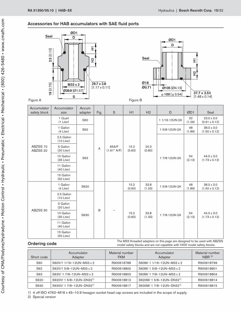
Short codeAccumulator
AdapterMaterial number
FKMAccumulator
AdapterMaterial number
NBR 2)
S60 S60V/1 1/16–12UN–M33 x 2 R900618788 S60M/ 1 1/16–12UN–M33 x 2 R900618799
S62 S62V/1 5/8–12UN–M33 x 2 R900618800 S60M/ 1 5/8–12UN–M33 x 2 R900618801
S63 S63V/ 1 7/8–12UN–M33 x 2 R900618803 S63M/ 1 7/8–12UN–M33 x 2 R900618804
S620 S620V/ 1 5/8–12UN–DN321) R900618813 S620M/ 1 5/8–12UN–DN321) R900618814
S630 S630V/ 1 7/8–12UN–DN321) R900618817 S630M/ 1 7/8–12UN–DN321) R900618815
1) 4 off ISO 4762–M16 x 45–10 .9 hexagon socket head cap screws are included in the scope of supply .2) Special version
Ordering.code
Accumulatorsafety block
Accumulatorsize
Accumadapter Fig . S H1 H2 D ØD1 Seal
ABZSS 10ABZSS 20
1 Quart(1 Liter) S60
A 65A/F(1 .61" A/F)
15 .2(0 .60)
20 .3(0 .80)
1 1/16-12UN-2A 32(1 .26)
23 .0 x 3 .0(0 .91 x 0 .12)
1 Gallon(4 Liter) S62 1 5/8-12UN-2A 48
(1 .89)38 .0 x 3 .0
(1 .50 x 0 .12)
2 .5 Gallon(10 Liter)
S63 1 7/8-12UN-2A 54(2 .13)
44 .0 x 3 .0(1 .73 x 0 .12)
5 Gallon(20 Liter)
10 Gallon(35 Liter)
11 Gallon(40 Liter)
15 Gallon(50 Liter)
ABZSS 30
1 Gallon(4 Liter) S620
B –
15 .2(0 .60)
33 .8(1 .33) 1 5/8-12UN-2A 48
(1 .89)38 .0 x 3 .0
(1 .50 x 0 .12)
2 .5 Gallon(10 Liter)
S630 15 .2(0 .60)
33 .8(1 .33) 1 7/8-12UN-2A 54
(2 .13)44 .0 x 3 .0
(1 .73 x 0 .12)
5 Gallon(20 Liter)
10 Gallon(35 Liter)
11 Gallon(40 Liter)
15 Gallon(50 Liter)
S
D
H1
H2
ØD1
[1.17 x 0.11]29.7 x 2.8
Ø39.9 [Ø1.57]
M33 x 2
2.5
[0.1
0]19
[0.7
5]
SealØD1
37.7 x 3.53[1.48 x 0.14]
H2
H1
D
Seal
Ø18Ø0.71 Ø105 [Ø4.13]
100 [ 3.94]
Accessories.for.HAB.accumulators.with.SAE.fluid.ports
Figure A Figure B
The M33 threaded adapters on this page are designed to be used with ABZSS model safety blocks and are not capatible with VAW model safety blocks .
RA.51350/05 .10..|..HAB–5X Hydraulics |..Bosch.Rexroth.Corp . 15/32
Court
esy
of CM
A/F
lodyn
e/H
ydra
dyn
e ▪
Motion C
ontr
ol ▪
Hyd
raulic
▪ P
neu
mat
ic ▪
Ele
ctrica
l ▪
Mec
han
ical
▪ (
800)
426-5
480 ▪
ww
w.c
maf
h.c
om
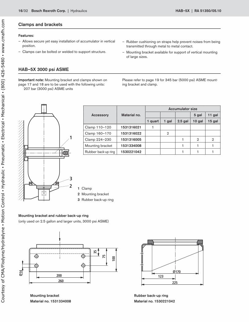
Clamps.and.brackets
Features:
– Allows secure yet easy installation of accumulator in vertical position .
– Clamps can be bolted or welded to support structure .
HAB–5X.3000.psi.ASME
1
3
2
14
200260
35
75
100
170123
225
Accessory Material.no .
Accumulator.size
5.gal 11.gal
1.quart 1.gal 2 .5.gal 10.gal 15.gal
Clamp 110–120 1531316021 1
Clamp 160–170 1531316022 2
Clamp 224–230 1531316005 1 2 2
Mounting bracket 1531334008 1 1 1
Rubber back-up ring 1530221042 1 1 1
1 Clamp
2 Mounting bracket
3 Rubber back-up ring
Mounting.bracket.and.rubber.back-up.ring
(only used on 2 .5 gallon and larger units, 3000 psi ASME)
Mounting.bracket.
Material.no ..1531334008
Rubber.back-up.ring.
Material.no ..1530221042
– Rubber cushioning on straps help prevent noises from being transmitted through metal to metal contact .
– Mounting bracket available for support of vertical mounting of large sizes .
Important.note: Mounting bracket and clamps shown on page 17 and 18 are to be used with the following units: 207 bar (3000 psi) ASME units
Please refer to page 19 for 345 bar (5000 psi) ASME mount-ing bracket and clamp .
16/32 Bosch.Rexroth.Corp . | .Hydraulics HAB–5X | RA.51350/05 .10
Court
esy
of CM
A/F
lodyn
e/H
ydra
dyn
e ▪
Motion C
ontr
ol ▪
Hyd
raulic
▪ P
neu
mat
ic ▪
Ele
ctrica
l ▪
Mec
han
ical
▪ (
800)
426-5
480 ▪
ww
w.c
maf
h.c
om
HAB–5X.3000.psi.ASME
Fry
Frx
Fa
D
A
H
C
MS
B
E
L
9
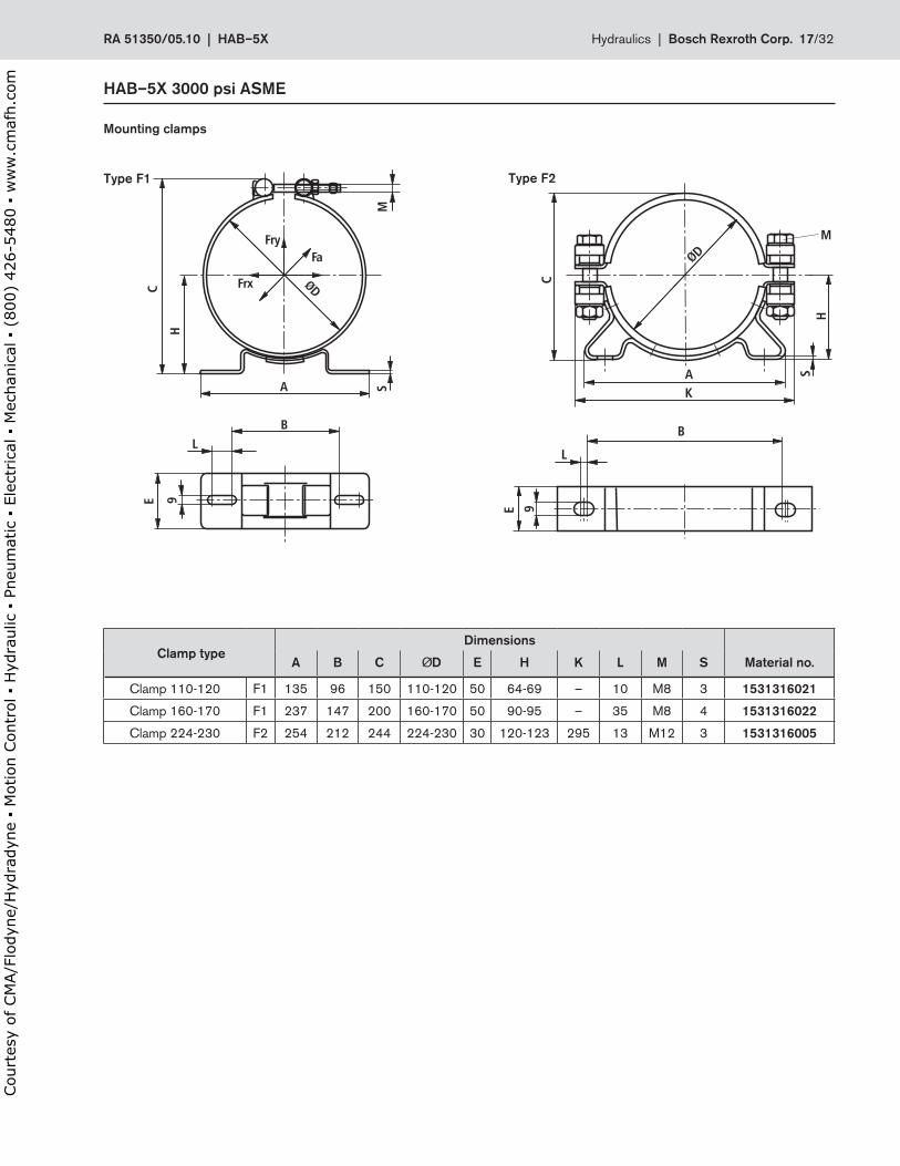
Mounting.clamps
Type.F1 Type.F2
B
L
E 9
AK
SH
D
C
M
.Clamp.typeDimensions
A B C D E H K L M S Material.no .
Clamp 110-120 F1 135 96 150 110-120 50 64-69 – 10 M8 3 1531316021
Clamp 160-170 F1 237 147 200 160-170 50 90-95 – 35 M8 4 1531316022
Clamp 224-230 F2 254 212 244 224-230 30 120-123 295 13 M12 3 1531316005
RA.51350/05 .10..|..HAB–5X Hydraulics |..Bosch.Rexroth.Corp . 17/32
Court
esy
of CM
A/F
lodyn
e/H
ydra
dyn
e ▪
Motion C
ontr
ol ▪
Hyd
raulic
▪ P
neu
mat
ic ▪
Ele
ctrica
l ▪
Mec
han
ical
▪ (
800)
426-5
480 ▪
ww
w.c
maf
h.c
om
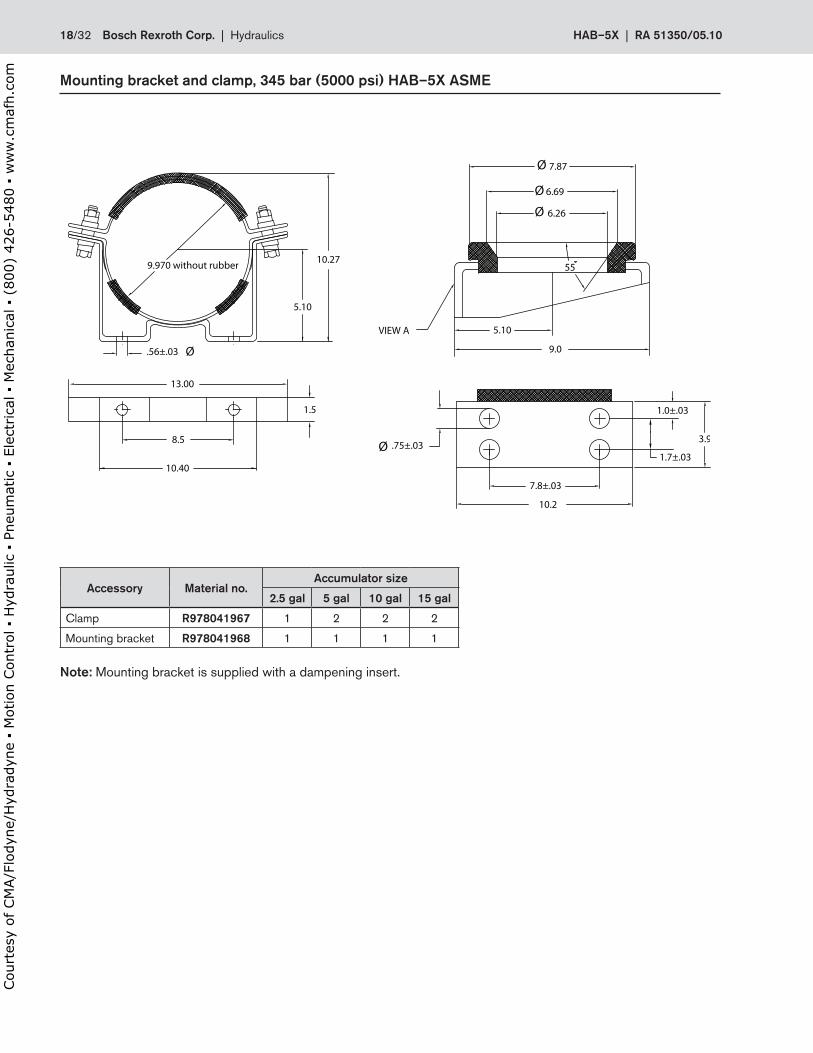
Mounting.bracket.and.clamp,.345.bar.(5000.psi).HAB–5X.ASME
Ø
8.5
10.40
13.00
5.10
10.27
.56±.03
9.970 without rubber 55
7.87
6.69
6.26
5.10
9.0
10.2
7.8±.03
3.9
1.0±.03
.75±.03
VIEW A
Ø
Ø
Ø
Ø
1.5
1.7±.03
Accessory Material.no .Accumulator.size
2 .5.gal 5.gal 10.gal 15.gal
Clamp R978041967 1 2 2 2
Mounting bracket R978041968 1 1 1 1
Note: Mounting bracket is supplied with a dampening insert .
18/32 Bosch.Rexroth.Corp . | .Hydraulics HAB–5X | RA.51350/05 .10
Court
esy
of CM
A/F
lodyn
e/H
ydra
dyn
e ▪
Motion C
ontr
ol ▪
Hyd
raulic
▪ P
neu
mat
ic ▪
Ele
ctrica
l ▪
Mec
han
ical
▪ (
800)
426-5
480 ▪
ww
w.c
maf
h.c
om
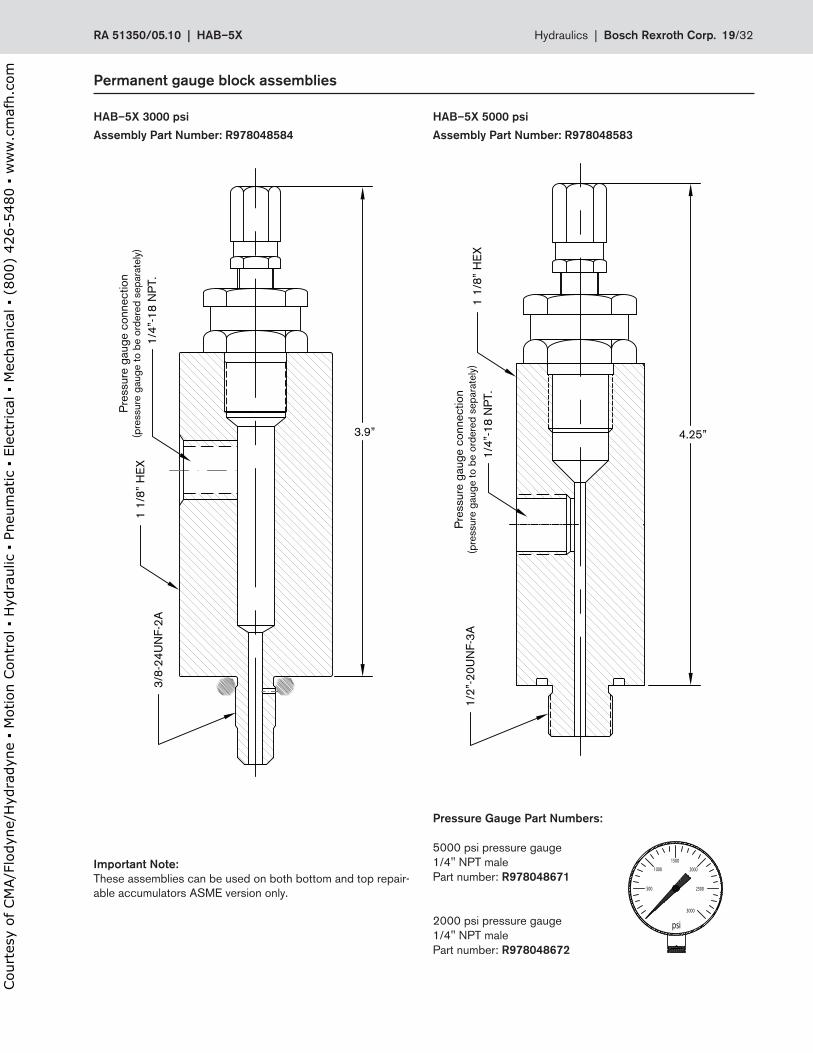
Permanent.gauge.block.assemblies
Important.Note:These assemblies can be used on both bottom and top repair-able accumulators ASME version only .
HAB–5X.5000.psi
Assembly.Part.Number:.R978048583
HAB–5X.3000.psi
Assembly.Part.Number:.R978048584
3.9” 4.25”
1 1/
8” H
EX
Pre
ssur
e ga
uge
conn
ectio
n(p
ress
ure
gaug
e to
be
orde
red
sepa
rate
ly)
3/8-
24U
NF-
2A
1/4”
-18
NP
T.1/
2”-2
0UN
F-3A
1 1/
8” H
EX
1/4”
-18
NP
T.
Pre
ssur
e ga
uge
conn
ectio
n(p
ress
ure
gaug
e to
be
orde
red
sepa
rate
ly)
1000
500 2500
psi
3000
1500
2000
Pressure.Gauge.Part.Numbers:
5000 psi pressure gauge1/4" NPT malePart number: R978048671
2000 psi pressure gauge1/4" NPT malePart number: R978048672
RA.51350/05 .10..|..HAB–5X Hydraulics |..Bosch.Rexroth.Corp . 19/32
Court
esy
of CM
A/F
lodyn
e/H
ydra
dyn
e ▪
Motion C
ontr
ol ▪
Hyd
raulic
▪ P
neu
mat
ic ▪
Ele
ctrica
l ▪
Mec
han
ical
▪ (
800)
426-5
480 ▪
ww
w.c
maf
h.c
om
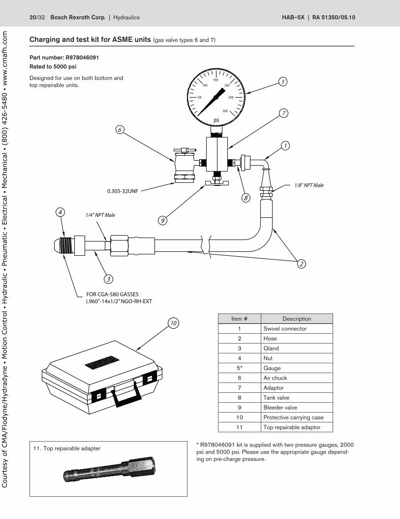
Charging.and.test.kit.for.ASME.units.(gas valve types 6 and 7)
Item # Description
1 Swivel connector
2 Hose
3 Gland
4 Nut
5* Gauge
6 Air chuck
7 Adaptor
8 Tank valve
9 Bleeder valve
10 Protective carrying case
11 Top repairable adaptor
* R978046091 kit is supplied with two pressure gauges, 2000 psi and 5000 psi . Please use the appropriate gauge depend-ing on pre-charge pressure .
10
3
1/4" NPT Male4
6
9
2
1/8" NPT Male
1
1000
500 2500
psi
3000
1500
2000
7
5
80.305-32UNF
FOR CGA-580 GASSES (.960”-14x1/2” NGO-RH-EXT
11 . Top repairable adapter
10
3
1/4" NPT Male4
6
9
2
1/8" NPT Male
1
1000
500 2500
psi
3000
1500
2000
7
5
80.305-32UNF
FOR CGA-580 GASSES (.960”-14x1/2” NGO-RH-EXT
Designed for use on both bottom andtop repairable units .
Part.number:.R978046091
Rated.to.5000.psi
20/32 Bosch.Rexroth.Corp . | .Hydraulics HAB–5X | RA.51350/05 .10
Court
esy
of CM
A/F
lodyn
e/H
ydra
dyn
e ▪
Motion C
ontr
ol ▪
Hyd
raulic
▪ P
neu
mat
ic ▪
Ele
ctrica
l ▪
Mec
han
ical
▪ (
800)
426-5
480 ▪
ww
w.c
maf
h.c
om
Accumulator.installation.&.operating.instructions
GeneralHydraulic circuits incorporating accumulators may store hydraulic oil under pressure depending on the function of the accumulator in the system . Therefore, the system may remain pressurized after the pump is turned off .
CAUTION - Prior to performing any maintenance or system modifications, bleed off any stored system pressure .
Completely release all hydraulic fluid pressure in a safe controlled manner using appropriate valving . Installation of an automatic accumulator discharge valve in the hydraulic circuit is recommended .
Accumulator repairs must be performed by trained hydraulic service personnel experienced in servicing accumulators . Con-tact your local authorized distributor for application or repair assistance .
Bladder.accumulators.Bladder accumulators will ship from the factory with a primer coating on the shell and with a rust preventative applied to other surfaces . The exception to this policy would be if Bosch Rexroth supplies a complete power unit assembly or accumula-tor stand and the customer specifies a particular finish coating on the entire unit .
It is the user's responsibility to provide sufficient corrosion pro-tection corresponding to the ambient conditions that the accu-mulator will be exposed to over the life time of the equipment . If a finish coat is desired, it is strongly recommended to mask the accumulator nameplate and all caution / warning labels prior to painting . Nameplate information is required for warranty evalu-ation and replacement purposes, therefore proper masking should preserve the condition of the nameplate for future use!
Bladder type accumulators are generally delivered with a nitrogen precharge pressure of approximately 25 psi (2 bar) for shipping purposes unless a higher pressure is specified in the accumulator model code . After installation and prior to initial start-up, the precharge pressure must be set to the application requirements, or machine manufacturer’s specifications .
Mounting.&.installationBladder type accumulators should be mounted in a vertical position with the fluid port assembly at the bottom . Mounting bladder type accumulators in other orientations may result in reduced bladder life . Please consult the factory if other mount-ing positions are necessary .
All accumulators must be rigidly installed using clamps and support brackets specifically designed for accumulator mount-ing . The fluid port assembly must not be used to support the weight of the accumulator .
CAUTION – DO NOT use gas valve or fluid port assembly as lifting points . The accumulator shell must not be altered . DO NOT weld or machine pressure vessel .
Improper installation may result in damage to the gas valve or fluid port assembly, accumulator shell, or seals . Exercise care not to paint over rating nameplate or the warning label .
Checking.the.gas.pre-charge.pressureBleed off hydraulic system pressure . After the accumulator has been put in service, the precharge pressure should be checked with an accumulator charging and testing device at least once in the first week . If this check reveals no loss in pressure, the precharge should be checked on the following schedule:
1st Check - 1 week
2nd Check - 3 months
3rd Check - 1 year
4th & Continued - yearly
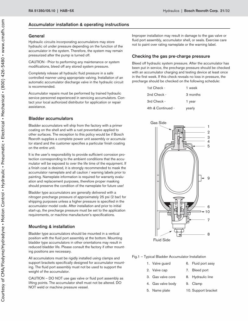
Fig .1 – Typical Bladder Accumulator Installation
1 . Valve guard 6 . Fluid port assy
2 . Valve cap 7 . Bleed port
3 . Gas valve core 8 . Hydraulic line
4 . Gas valve body 9 . Clamp
5 . Name plate 10 . Support bracket
RA.51350/05 .10..|..HAB–5X Hydraulics |..Bosch.Rexroth.Corp . 21/32
Court
esy
of CM
A/F
lodyn
e/H
ydra
dyn
e ▪
Motion C
ontr
ol ▪
Hyd
raulic
▪ P
neu
mat
ic ▪
Ele
ctrica
l ▪
Mec
han
ical
▪ (
800)
426-5
480 ▪
ww
w.c
maf
h.c
om
If the gas precharge is low, investigate cause and correct . Possible causes of lost precharge pressure includes leaking or damaged gas valve, or damaged bladder .
Testing.pre-charge.pressure.Completely release accumulator hydraulic system pressure in a safe controlled manner . Install the charging and testing device onto the gas valve . Measure the pre-charge pressure using the gauge supplied in the charge kit .
Charging.the.accumulatorCAUTION - USE only dry 99 .99% pure nitrogen for charging accumulators . NEVER USE OXYGEN OR AIR, due to the risk of explosion .
Close the drain valve on the charging and testing device and connect the hose to the nitrogen bottle .
Remove the valve guard and valve cap and screw the charging and testing device onto the gas valve . More detail information is provided in the instruction sheet furnished with the charging and testing device . Open the gas shut-off valve on the nitrogen bottle and allow the gas to flow slowly into the accumulator . Close the shut-off valve frequently and check the value of the precharge pressure on the gauge .
If the precharge pressure is too high, it may be reduced by opening the drain valve and allowing some nitrogen to escape .
Note: The precharge pressure will vary depending on the gas temperature . Once the desired precharge is reached, it is necessary to wait 2 minutes until the gas temperature has equalized .
Once again the precharge pressure needs to be checked and adjusted if necessary .
Unscrew the charging and testing device and replace the valve guard and cap (see Fig . 1, Item #1 & #2) A check for leaks with a soapy solution should follow . If a leak is found, it should be repaired following recommended repair procedures . If the gas valve core is replaced, use only valve cores approved for accumulator service, NEVER USE AN AUTOMOTIVE TYPE VALVE CORE .
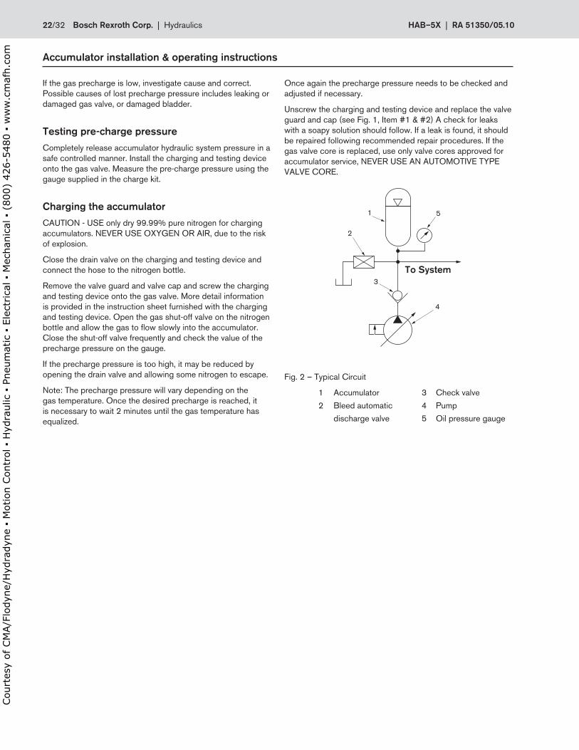
Fig . 2 – Typical Circuit
1 Accumulator 3 Check valve
2 Bleed automatic 4 Pump
discharge valve 5 Oil pressure gauge
Accumulator.installation.&.operating.instructions
22/32 Bosch.Rexroth.Corp . | .Hydraulics HAB–5X | RA.51350/05 .10
Court
esy
of CM
A/F
lodyn
e/H
ydra
dyn
e ▪
Motion C
ontr
ol ▪
Hyd
raulic
▪ P
neu
mat
ic ▪
Ele
ctrica
l ▪
Mec
han
ical
▪ (
800)
426-5
480 ▪
ww
w.c
maf
h.c
om
Intended.use
Rexroth bladder type accumulators HAB . .-5X are intended forthe setup of hydraulic drive systems in the field of stationarymachine-building and plant construction .In mobile applications or applications, in which accelerationforces act on the bladder-type accumulator during operationaccording to the intended purpose, the use is subject to ap-proval by the responsible Bosch Rexroth product manager .Please contact the technical sales organization .
.Warning.
Never.carry.out.any.welding,.soldering.or.mechanical.workon.the.accumulator.vessel!
–Risk of explosion during welding and soldering! – Risk of bursting and loss of the operating permis- sion in the case of mechanical working! Never charge hydraulic accumulators with oxygen or air . Risk of explosion!
Before carrying out any work on hydraulic systems, depressur-ize the system and secure it against restarting!Improper mounting can lead to severe accidents!
Commissioning.must.exclusively.be.carried.out.by.quali-fied.personnel .
Safety.notes.on.hydraulic.accumulators
Rexroth HAB . .-5X bladder-type accumulators are not intendedfor private use . They must not be used in potentially explosive atmospheres in accordance with Directive 94/9/EC (ATEX) .
Before commissioning and during operation of hydraulic accu-mulators, observe the regulations valid at the place of installa-tion .
The operator is solely responsible for observing applicable regulations .
Documents included in the scope of supply must be properlykept; they are required by the surveyor for recurring inspec-tions .
The.operator.should.never.attempt.to.adjust,.loosen,.or.remove.the.bleeder.port.plug.(page.21,.figure.1,.item.#7).without.completely.depressurizing.the.system ..Installing.replacement.bleeder.plugs.not.approved.or.supplied.from.the.manufacturer.is.strickly.forbidden .
Legal.stipulations
Hydraulic accumulators are pressure vessels and are subject to the national regulations and ordinances valid at the place of installation .
Safety.equipment
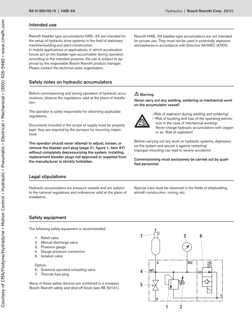
The following safety equipment is recommended:
1 . Relief valve2 . Manual discharge valve3 . Pressure gauge4 . Gauge pressure connection5 . Isolation valve
Option:6 . Solenoid operated unloading valve7 . Thermal fuse plug
Many of these safety devices are combined in a compact Bosch Rexroth safety and shut-off block (see RE 50131) .
M1
M2A
x
PT
21
3 67
4
5
Special rules must be observed in the fields of shipbuilding, aircraft construction, mining, etc .
�
RA.51350/05 .10..|..HAB–5X Hydraulics |..Bosch.Rexroth.Corp . 23/32
Court
esy
of CM
A/F
lodyn
e/H
ydra
dyn
e ▪
Motion C
ontr
ol ▪
Hyd
raulic
▪ P
neu
mat
ic ▪
Ele
ctrica
l ▪
Mec
han
ical
▪ (
800)
426-5
480 ▪
ww
w.c
maf
h.c
om
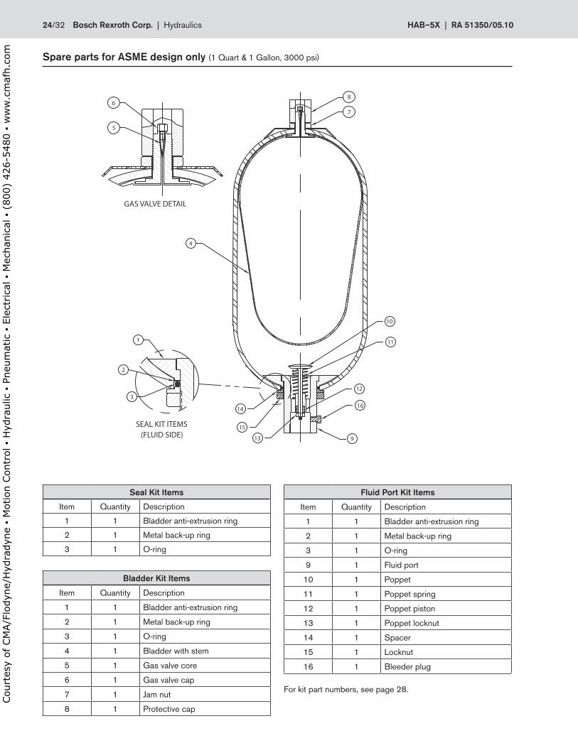
Spare.parts.for.ASME.design.only.(1 Quart & 1 Gallon, 3000 psi)
(FLUID SIDE)SEAL KIT ITEMS
3
2
1
GAS VALVE DETAIL
7
86
5
1614
15
4
10
11
12
913
Seal.Kit.Items
Item Quantity Description
1 1 Bladder anti-extrusion ring
2 1 Metal back-up ring
3 1 O-ring
Bladder.Kit.Items
Item Quantity Description
1 1 Bladder anti-extrusion ring
2 1 Metal back-up ring
3 1 O-ring
4 1 Bladder with stem
5 1 Gas valve core
6 1 Gas valve cap
7 1 Jam nut
8 1 Protective cap
Fluid.Port.Kit.Items
Item Quantity Description
1 1 Bladder anti-extrusion ring
2 1 Metal back-up ring
3 1 O-ring
9 1 Fluid port
10 1 Poppet
11 1 Poppet spring
12 1 Poppet piston
13 1 Poppet locknut
14 1 Spacer
15 1 Locknut
16 1 Bleeder plug
For kit part numbers, see page 28 .
24/32 Bosch.Rexroth.Corp . | .Hydraulics HAB–5X | RA.51350/05 .10
Court
esy
of CM
A/F
lodyn
e/H
ydra
dyn
e ▪
Motion C
ontr
ol ▪
Hyd
raulic
▪ P
neu
mat
ic ▪
Ele
ctrica
l ▪
Mec
han
ical
▪ (
800)
426-5
480 ▪
ww
w.c
maf
h.c
om
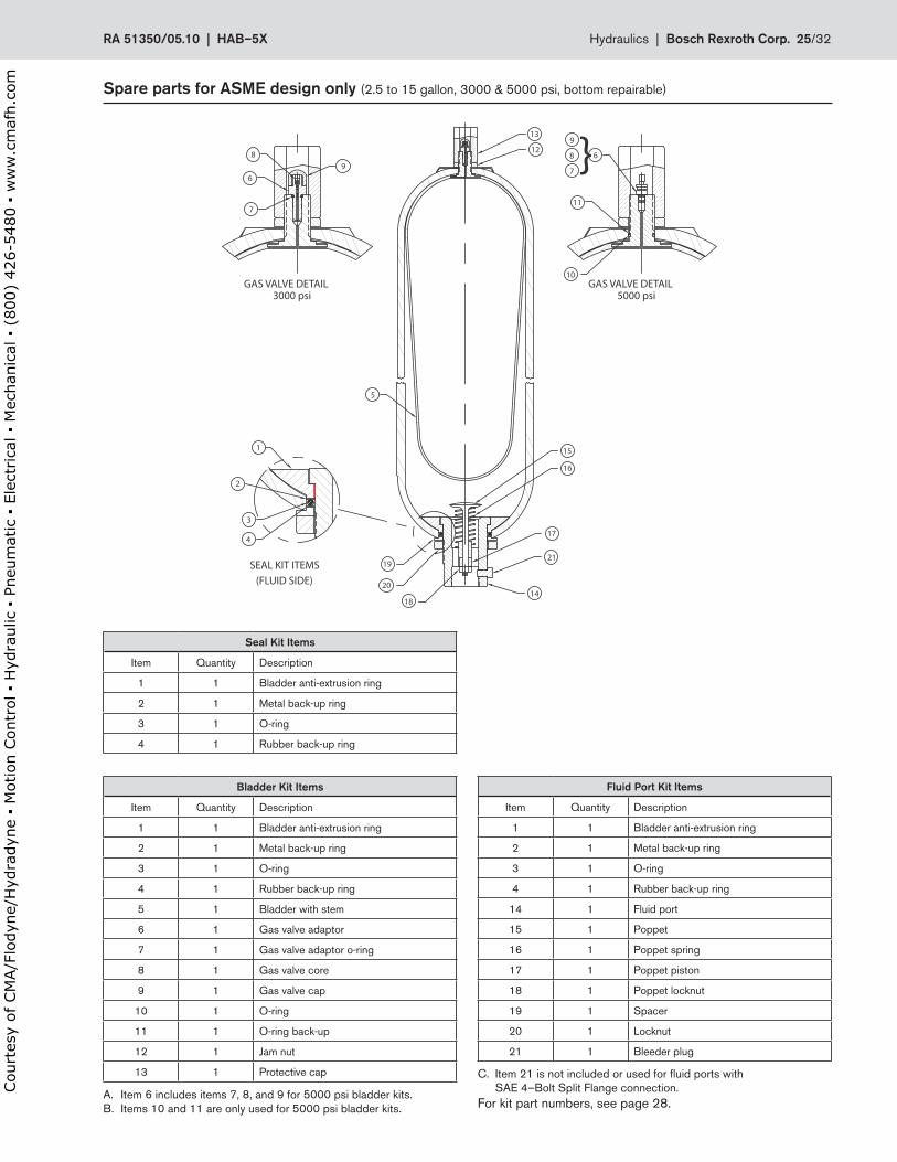
Spare.parts.for.ASME.design.only.(2 .5 to 15 gallon, 3000 & 5000 psi, bottom repairable)
Seal.Kit.Items
Item Quantity Description
1 1 Bladder anti-extrusion ring
2 1 Metal back-up ring
3 1 O-ring
4 1 Rubber back-up ring
Bladder.Kit.Items
Item Quantity Description
1 1 Bladder anti-extrusion ring
2 1 Metal back-up ring
3 1 O-ring
4 1 Rubber back-up ring
5 1 Bladder with stem
6 1 Gas valve adaptor
7 1 Gas valve adaptor o-ring
8 1 Gas valve core
9 1 Gas valve cap
10 1 O-ring
11 1 O-ring back-up
12 1 Jam nut
13 1 Protective cap
Fluid.Port.Kit.Items
Item Quantity Description
1 1 Bladder anti-extrusion ring
2 1 Metal back-up ring
3 1 O-ring
4 1 Rubber back-up ring
14 1 Fluid port
15 1 Poppet
16 1 Poppet spring
17 1 Poppet piston
18 1 Poppet locknut
19 1 Spacer
20 1 Locknut
21 1 Bleeder plug
C . Item 21 is not included or used for fluid ports with SAE 4–Bolt Split Flange connection .For kit part numbers, see page 28 .
A . Item 6 includes items 7, 8, and 9 for 5000 psi bladder kits .B . Items 10 and 11 are only used for 5000 psi bladder kits .
8
7
6
13
12
9
14
5
4
3
2
1
GAS VALVE DETAIL
SEAL KIT ITEMS(FLUID SIDE)
GAS VALVE DETAIL3000 psi 5000 psi
6
11
10
15
16
17
21
18
19
20
8 }9
7
RA.51350/05 .10..|..HAB–5X Hydraulics |..Bosch.Rexroth.Corp . 25/32
Court
esy
of CM
A/F
lodyn
e/H
ydra
dyn
e ▪
Motion C
ontr
ol ▪
Hyd
raulic
▪ P
neu
mat
ic ▪
Ele
ctrica
l ▪
Mec
han
ical
▪ (
800)
426-5
480 ▪
ww
w.c
maf
h.c
om
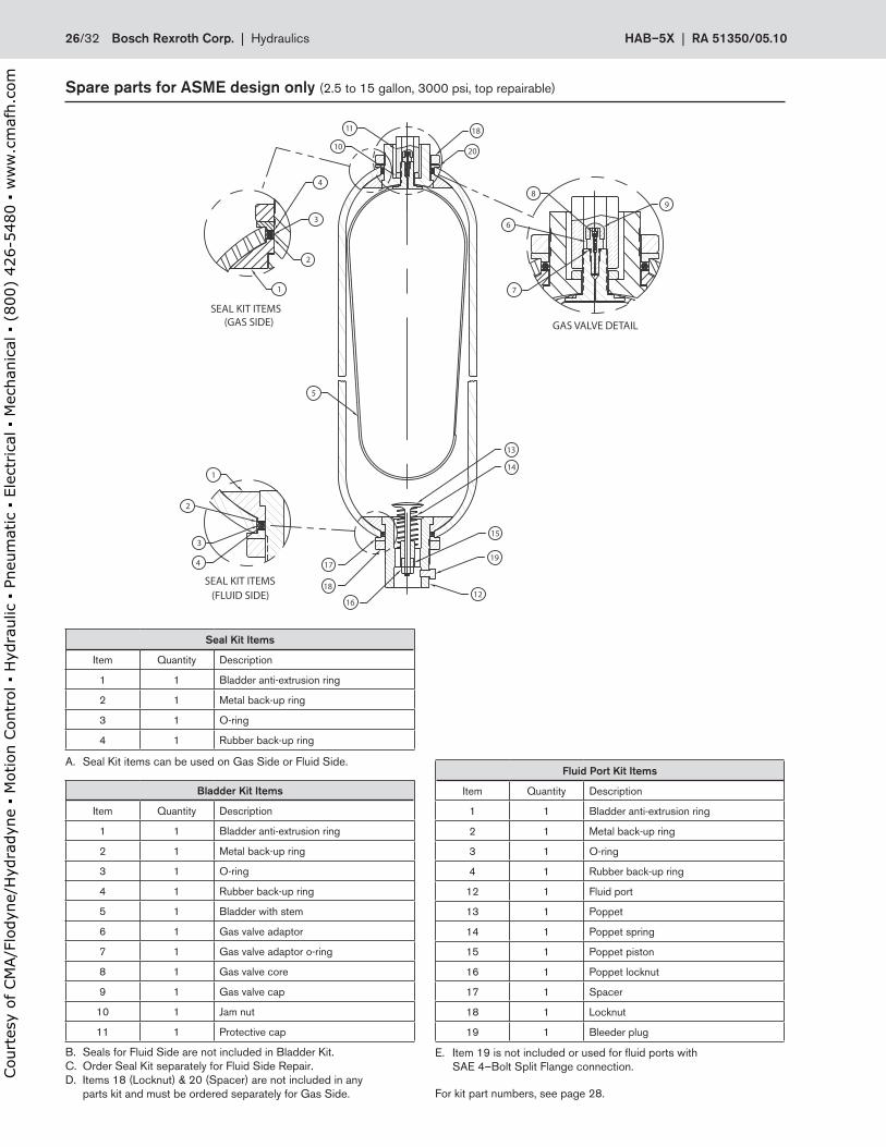
Seal.Kit.Items
Item Quantity Description
1 1 Bladder anti-extrusion ring
2 1 Metal back-up ring
3 1 O-ring
4 1 Rubber back-up ring
Bladder.Kit.Items
Item Quantity Description
1 1 Bladder anti-extrusion ring
2 1 Metal back-up ring
3 1 O-ring
4 1 Rubber back-up ring
5 1 Bladder with stem
6 1 Gas valve adaptor
7 1 Gas valve adaptor o-ring
8 1 Gas valve core
9 1 Gas valve cap
10 1 Jam nut
11 1 Protective cap
Fluid.Port.Kit.Items
Item Quantity Description
1 1 Bladder anti-extrusion ring
2 1 Metal back-up ring
3 1 O-ring
4 1 Rubber back-up ring
12 1 Fluid port
13 1 Poppet
14 1 Poppet spring
15 1 Poppet piston
16 1 Poppet locknut
17 1 Spacer
18 1 Locknut
19 1 Bleeder plug
Spare.parts.for.ASME.design.only.(2 .5 to 15 gallon, 3000 psi, top repairable)
E . Item 19 is not included or used for fluid ports with SAE 4–Bolt Split Flange connection .
For kit part numbers, see page 28 .
B . Seals for Fluid Side are not included in Bladder Kit .C . Order Seal Kit separately for Fluid Side Repair .D . Items 18 (Locknut) & 20 (Spacer) are not included in any parts kit and must be ordered separately for Gas Side .
A . Seal Kit items can be used on Gas Side or Fluid Side .
1
2
3
4
5
1
4
3
2
SEAL KIT ITEMS
SEAL KIT ITEMS(GAS SIDE)
(FLUID SIDE)
GAS VALVE DETAIL
9
6
7
8
13
14
15
19
1216
18
17
10
11
20
18
26/32 Bosch.Rexroth.Corp . | .Hydraulics HAB–5X | RA.51350/05 .10
Court
esy
of CM
A/F
lodyn
e/H
ydra
dyn
e ▪
Motion C
ontr
ol ▪
Hyd
raulic
▪ P
neu
mat
ic ▪
Ele
ctrica
l ▪
Mec
han
ical
▪ (
800)
426-5
480 ▪
ww
w.c
maf
h.c
om
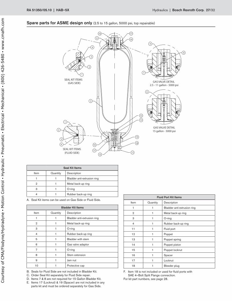
Spare.parts.for.ASME.design.only.(2 .5 to 15 gallon, 5000 psi, top repairable)
Seal.Kit.Items
Item Quantity Description
1 1 Bladder anti-extrusion ring
2 1 Metal back-up ring
3 1 O-ring
4 1 Rubber back-up ring
Bladder.Kit.Items
Item Quantity Description
1 1 Bladder anti-extrusion ring
2 1 Metal back-up ring
3 1 O-ring
4 1 Rubber back-up ring
5 1 Bladder with stem
6 1 Gas valve adaptor
7 1 O-ring
8 1 Stem extension
9 1 Jam nut
10 1 Protective cap
Fluid.Port.Kit.Items
Item Quantity Description
1 1 Bladder anti-extrusion ring
2 1 Metal back-up ring
3 1 O-ring
4 1 Rubber back-up ring
11 1 Fluid port
12 1 Poppet
13 1 Poppet spring
14 1 Poppet piston
15 1 Poppet locknut
16 1 Spacer
17 1 Locknut
18 1 Bleeder plug
F . Item 18 is not included or used for fluid ports with SAE 4–Bolt Split Flange connection .For kit part numbers, see page 28 .
B . Seals for Fluid Side are not included in Bladder Kit .C . Order Seal Kit separately for Fluid Side repair .D . Items 7 & 8 are not required for 15 Gallon Bladder Kit .E . Items 17 (Locknut) & 19 (Spacer) are not included in any parts kit and must be ordered separately for Gas Side .
A . Seal Kit items can be used on Gas Side or Fluid Side .
1
2
3
4
5
1
4
3
2
SEAL KIT ITEMS
SEAL KIT ITEMS(GAS SIDE)
(FLUID SIDE)
8
7
12
13
14
18
1115
17
16
15 gallon - 5000 psiGAS VALVE DETAIL
2.5 - 11 gallon - 5000 psiGAS VALVE DETAIL
6
6
10
9
17
19
RA.51350/05 .10..|..HAB–5X Hydraulics |..Bosch.Rexroth.Corp . 27/32
Court
esy
of CM
A/F
lodyn
e/H
ydra
dyn
e ▪
Motion C
ontr
ol ▪
Hyd
raulic
▪ P
neu
mat
ic ▪
Ele
ctrica
l ▪
Mec
han
ical
▪ (
800)
426-5
480 ▪
ww
w.c
maf
h.c
om
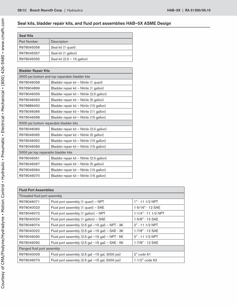
Seal.kits,.bladder.repair.kits,.and.fluid.port.assemblies.HAB–5X.ASME.Design
Seal.Kits
Part Number Description
R978045056 Seal kit (1 quart)
R978045057 Seal kit (1 gallon)
R978045055 Seal kit (2 .5 – 15 gallon)
Bladder.Repair.Kits
3000 psi bottom and top repairable bladder kits
R978046058 Bladder repair kit – Nitrile (1 quart)
R978904899 Bladder repair kit – Nitrile (1 gallon)
R978046059 Bladder repair kit – Nitrile (2 .5 gallon)
R978046063 Bladder repair kit – Nitrile (5 gallon)
R978889450 Bladder repair kit – Nitrile (10 gallon)
R978046066 Bladder repair kit – Nitrile (11 gallon)
R978046068 Bladder repair kit – Nitrile (15 gallon)
5000 psi bottom repairable bladder kits
R978046060 Bladder repair kit – Nitrile (2 .5 gallon)
R978046065 Bladder repair kit – Nitrile (5 gallon)
R978046062 Bladder repair kit – Nitrile (10 gallon)
R978046069 Bladder repair kit – Nitrile (15 gallon)
5000 psi top repairable bladder kits
R978046061 Bladder repair kit – Nitrile (2 .5 gallon)
R978046067 Bladder repair kit – Nitrile (5 gallon)
R978046064 Bladder repair kit – Nitrile (10 gallon)
R978046070 Bladder repair kit – Nitrile (15 gallon)
Fluid.Port.Assemblies
Threaded fluid port assembly
R978046071 Fluid port assembly (1 quart) – NPT 1" - 11 1/2 NPT
R978040023 Fluid port assembly (1 quart) – SAE 1-5/16" - 12 SAE
R978046072 Fluid port assembly (1 gallon) – NPT 1-1/4" - 11 1/2 NPT
R978040024 Fluid port assembly (1 gallon) – SAE 1-5/8" - 12 SAE
R978046074 Fluid port assembly (2 .5 gal –15 gal) – NPT - 3K 2" - 11 1/2 NPT
R978040022 Fluid port assembly (2 .5 gal –15 gal) – SAE - 3K 1-7/8" - 12 SAE
R978046090 Fluid port assembly (2 .5 gal –15 gal) – NPT - 5K 2" - 11 1/2 NPT
R978046092 Fluid port assembly (2 .5 gal –15 gal) – SAE - 5K 1-7/8" - 12 SAE
Flanged fluid port assembly
R978040009 Fluid port assembly (2 .5 gal –15 gal, 3000 psi) 2" code 61
R978046073 Fluid port assembly (2 .5 gal –15 gal, 5000 psi) 1-1/2" code 62
28/32 Bosch.Rexroth.Corp . | .Hydraulics HAB–5X | RA.51350/05 .10
Court
esy
of CM
A/F
lodyn
e/H
ydra
dyn
e ▪
Motion C
ontr
ol ▪
Hyd
raulic
▪ P
neu
mat
ic ▪
Ele
ctrica
l ▪
Mec
han
ical
▪ (
800)
426-5
480 ▪
ww
w.c
maf
h.c
om

Notes
RA.51350/05 .10..|..HAB–5X Hydraulics |..Bosch.Rexroth.Corp . 29/32
Court
esy
of CM
A/F
lodyn
e/H
ydra
dyn
e ▪
Motion C
ontr
ol ▪
Hyd
raulic
▪ P
neu
mat
ic ▪
Ele
ctrica
l ▪
Mec
han
ical
▪ (
800)
426-5
480 ▪
ww
w.c
maf
h.c
om

Notes
30/32 Bosch.Rexroth.Corp . | .Hydraulics HAB–5X | RA.51350/05 .10
Court
esy
of CM
A/F
lodyn
e/H
ydra
dyn
e ▪
Motion C
ontr
ol ▪
Hyd
raulic
▪ P
neu
mat
ic ▪
Ele
ctrica
l ▪
Mec
han
ical
▪ (
800)
426-5
480 ▪
ww
w.c
maf
h.c
om

Notes
RA.51350/05 .10..|..HAB–5X Hydraulics |..Bosch.Rexroth.Corp . 31/32
Court
esy
of CM
A/F
lodyn
e/H
ydra
dyn
e ▪
Motion C
ontr
ol ▪
Hyd
raulic
▪ P
neu
mat
ic ▪
Ele
ctrica
l ▪
Mec
han
ical
▪ (
800)
426-5
480 ▪
ww
w.c
maf
h.c
om
Bosch Rexroth Corp .Industrial Hydraulics2315 City Line RoadBethlehem, PA 18017-2131USATelephone (610) 694-8300Facsimile (610) 694-8467www .boschrexroth-us .com
© This document, as well as the data, specifications and other information set forth in it, are the exclusive property of Bosch Rexroth Corporation . Without their consent it may not be reproduced or given to third parties .
The data specified above only serve to describe the product . No statements concerning a certain condition or suitability for a certain application can be derived from our information . The information given does not release the user from the obligation of own judgment and verification . It must be remembered that our products are subject to a natural process of wear and aging .
. Bosch.Rexroth.Corp . | .Hydraulics HAB–5X | RA.51350/05 .10
Court
esy
of CM
A/F
lodyn
e/H
ydra
dyn
e ▪
Motion C
ontr
ol ▪
Hyd
raulic
▪ P
neu
mat
ic ▪
Ele
ctrica
l ▪
Mec
han
ical
▪ (
800)
426-5
480 ▪
ww
w.c
maf
h.c
om