Embed Size (px)
Citation preview
Blade - A Timing Violation Resilient AsynchronousTemplate
Dylan Hand∗, Matheus Trevisan Moreira∗†, Hsin-Ho Huang∗, Danlei Chen∗, Frederico Butzke‡, Zhichao Li∗,Matheus Gibiluka†, Melvin Breuer∗, Ney Laert Vilar Calazans†, and Peter A. Beerel∗§
∗Ming Hsieh Dept. of Electrical Engineering, University of Southern California, Los Angeles, CA, USA†Faculty of Informatics, Pontifícia Universidade Católica do Rio Grande do Sul, Porto Alegre, Brazil‡Computer Science Department, Universidade de Santa Cruz do Sul, Santa Cruz do Sul, Brazil
Abstract—Resilient designs offer the promise to remove in-creasingly large margins due to process, voltage, and temperaturevariations and take advantage of average-case data. However,proposed synchronous resilient schemes have either suffered frommetastability or require modifying the architecture to add replay-based logic that recovers from timing errors, which leads to hightiming error penalties and poses a design challenge in modernprocessors. This paper presents an asynchronous bundled-dataresilient template called Blade that is robust to metastabilityissues, requires no replay-based logic, and has low timing errorpenalties. The template is supported by an automated design flowthat synthesizes synchronous RTL designs to gate-level asynchro-nous Blade designs. The benefits of this flow are illustrated onPlasma, a 3-stage OpenCore MIPS CPU. Our results demonstratethat a nominal area overhead of the asynchronous templateof less than 10% leads to a 19% performance boost over thesynchronous design due to average-case data and a 30-40%improvement when synchronous PVT margins are considered.
I. INTRODUCTION
Traditional synchronous designs must incorporate timingmargin to ensure correct operation under worst-case delayscaused by process, voltage, and temperature (PVT) varia-tions as well as data-dependency [1]. Different asynchronoustemplates have been proposed to address this problem (e.g.,[2]). Quasi-delay-insensitive (QDI) templates use completionsignal logic, which makes them robust to delay variations atthe cost of increased area and high switching activity dueto a return to zero paradigm [3]. Bundled-data templates(e.g., micropipelines [4]) use delay lines matched to single-rail combinational logic, providing a low area, low switchingactivity asynchronous solution (e.g., [5]). However, the delaylines must be implemented with sufficiently large margins inthe presence of on-chip variations, reducing the advantages ofthis approach. Researchers have proposed different solutions tomitigate these margins, such as duplicating the bundled-datadelay lines [6], constraining the design to regular structuressuch as PLAs [7], and using soft latches [8].
Meanwhile, the synchronous research community haveinvestigated various methods to reduce timing margins inclocked designs. Among these efforts, we highlight resilientdesign techniques, which rely on extra logic to detect andrecover from timing violations [9]–[11]. However, many of theproposed techniques are susceptible to metastability [12] or re-quire adding replay-based logic, often at an architectural level,
§ Peter A. Beerel is also a Chief Scientist, Technology Development atIntel, Calabasas, CA 91302.
to recover from these violations, which can be a challenge inmodern processors and lead to high timing error penalties.
This paper presents a new asynchronous bundled-data tem-plate called Blade, which couples the architectural benefitsof resilient techniques with the flexibility of asynchronouspipelines. In particular, Blade enables average case perfor-mance, is robust to metastability issues, requires no replay-based logic, and has very low timing error penalties.
Blade uses single-rail logic, reconfigurable delay lines, anderror-detecting latches [1] that reliably detect timing viola-tions. The template implements a novel speculative hand-shaking paradigm that improves average-case performanceby taking advantage of the fact that errors will have a lowprobability of occurrence. Moreover, it is supported by anautomated design flow that synthesizes synchronous RTL de-signs to gate-level Blade designs. The flow includes automaticFF to latch conversion, retiming, and resynthesis to furtherimprove average-case performance while minimizing area. Thepotential benefits of Blade and this flow are explored in acase study using a 3-stage MIPS OpenCore CPU, Plasma [13],targeting an FDSOI 28nm technology. We compare the gate-level Blade design to the equivalent synchronous design, andpost-synthesis results demonstrate that for an area overhead of8.4%, the Blade version of Plasma achieves a 19% averageperformance boost. With the removal of synchronous PVTmargins, we estimate a 30%-40% improvement in perfor-mance.
The remainder of this paper is organized as follows. Sec-tion II introduces the Blade template, explores the maincomponents, and details the associated timing assumptions andoverheads. Section III documents the automated conversionprocess used to synthesize Plasma and compares the perfor-mance between the asynchronous and synchronous designs.Finally, Sections IV and V provide discussion of the casestudy results, general observations, conclusions, and severalopportunities for future optimizations and applications.
II. BLADE TEMPLATE
The proposed Blade template, as shown in Figure 1, usessingle-rail logic followed by error detecting latches (EDLs),two reconfigurable delay lines, and an asynchronous Bladecontroller. The first delay line is of duration δ and controlswhen the EDL becomes transparent, allowing the data topropagate through the latch. The Blade controller speculativelyassumes that the data at the input of the EDL is stable whenit becomes transparent and thus sends an output request along

EDL(Error
Detecting
Latch)
R.dataCombinational
Logic
BladeController
L.data
Reconfigurable Delay Line (δ) Err
Δ L.ack
L.req
LE.req
LE.ack
R.ack
RE.ack
R.req
RE.req
Sam
ple
CLK
Blade StageError Detection Logic
2
Fig. 1: The Blade template
the typical bundled data channel L/R. The second delay line,with duration ∆, defines the time window during which theEDL is transparent. If data changes during this window, butstabilizes before the latch becomes opaque, it is recordedas a timing violation, which can subsequently be corrected.Consequently, ∆ defines a timing resiliency window (TRW)after δ during which the speculative timing assumption maybe safely violated.
In particular, if the combinational output transitions duringthe TRW, the error detection logic flags a timing violation byasserting its Err signal, which is sampled by the controller.The Blade controller then communicates with its right neigh-bor using a novel handshaking protocol implemented with anadditional error channel (RE/LE) to recover from the timingviolation by delaying the opening of the next stage’s latch, aswill be described in more detail in Section II-B.
A. Error Detection Logic
As illustrated in Figure 2, the error detection logic consistsof EDLs, generalized C-elements, and Q-Flops [14]. Whilethere are many possible implementations of EDLs (e.g., [1],[9], [11], [15]), we implemented a custom design based onthe Transition Detecting Time Borrowing (TDTB) latchesproposed in [1], a functional block diagram of which is shownin Figure 2. The already low overhead of the TDTB is furtherreduced by integrating the transition detector into the pass-gatelatch circuit, where inherit internal latch delays are repurposedto replace the tTD delay line connected to the XOR gate. TheXOR gate itself is also optimized at the transistor level toimprove the transition detector’s sensitivity [15].
The generalized C-elements in Figure 2 are also designed atthe transistor level using the flow proposed in [16] and act totemporarily remember violations detected by the EDL duringthe high phase of CLK. While the input connected to CLKis symmetric, i.e. required for both low-to-high and high-to-low output transitions, the X signal from the EDL feeds apositive asymmetric input, which can only affect low-to-hightransitions. Accordingly, the generalized C-element will switchto 0 if CLK is at 0 and to 1 only if both CLK and the X inputare at 1. This creates a memory cell that temporarily storesany violation detected by the EDL during the high phase ofCLK, i.e. during the TRW. Note that a compensation delay isadded by the tcomp delay line, the purpose of which will beexplained in Section II-E.
Under normal operation, the pulse on X will be sufficientlylarge to guarantee the output node of the C-element is fullycharged, indicating an error has occurred while CLK is high,as outlined in [15]. However, because the data may violatethe setup time of the EDLs, the X signal and the C-elementmay exhibit metastablity, as will be further discussed in Sec-tion II-C. To ensure safe operation, this metastability must befiltered out before reaching the main controller. In synchronousdesigns, the filtering would be handled through multi-stagesynchronizers increasing the latency of error detection dramat-ically. In contrast, the output of the C-element in the Bladetemplate is sampled at the end of the TRW using a Q-Flop,which contains a metastability filter that prevents the dual railoutput signal, Err, from ever becoming metastable, even if theC-element is in a metastable state. The Blade controller simplywaits for the dual-rail Err signal to evaluate to determinewhether or not an error occured, gracefully stalling untilmetastabiilty is resolved.
To minimize area overheads due to error detection, it isdesirable to amortize the cost of the C-elements and Q-Flops across multiple EDLs. As shown in Figure 2, a 4-inputgeneralized C-element can combine the X signals of 3 EDLsusing parallel inputs such that an error from any of the threeEDLs triggers the C-element output to fire. An OR gate canfurther combine 4 C-elements before reaching a Q-Flop. In thisscenario, a single Q-Flop will accurately catch errors and filtermetastability from 12 EDLs. Counterintuitively, this addeddelay provides timing benefits in addition to multifaceted areasavings, as will be further explored in Sections II-E and II-F.Note that the C-element’s static implementation [3] makes itundiserable to have more than 4-inputs as the PMOS stackgrows too large.
To further reduce area and power overheads of the errordetection logic, two additional micro-architectural optimiza-tions are considered. First, not every pipeline stage need beerror-detecting and non error-detecting stages can time borrow.Time-borrowing stages permit data to pass through the latchduring the entire time it is transparent without flagging anyviolations. In particular, we found alternating between error-detecting and time-borrowing stages can work well as this
Out
CLK
In
Sample
Error Detection Logic
Controller
C+
D Q
delay
Err
0
Latch
delay
X
EDL
Q-Flop
Err
1
From other C-elements
{
{ {
From other Q-Flops
tcomp
tTD
Fig. 2: Error detection logic including block level diagram oferror detecting latch
Stage 1CLK
Stage 2CLK
Stage 3CLK
Stage 4CLK
TimingViolation
Extend
Instruction 1
δ δ+Δ δ
Instruction 2
δ
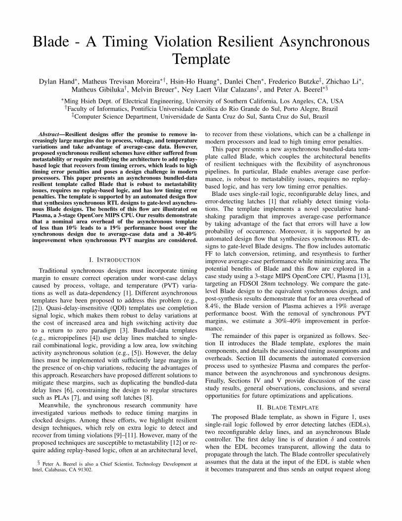
Fig. 3: Timing diagram of Blade template
effectively halves the overhead of error detection logic whilestill providing sufficient resiliency. Secondly, we define astage’s critical path as the longest possible input to outputpath in the combination logic, which sets the endpoint of theTRW. If another path has delay within the TRW it is said to be"near-critical". Only latches that terminate near-critical paths1
need be error detecting, further reducing the number of EDLsrequired in the entire design.
B. Speculative Handshaking ProtocolThe proposed Blade template implements a new form of
asynchronous handshaking: speculative handshaking. To un-derstand this protocol, we first introduce the expected behaviorof the CLK signals of four Blade stages in a pipeline, shown inFigure 3. As Instructions 1 and 2 flow through the pipeline, thearrows indicate the dependency of one clock signal on another.Instruction 1, shown in red, launches from Stage 1 at time zero.While Stage 2’s latch is transparent, a timing violation occursindicating the δ delay line in Stage 1 was shorter in durationthan the combinational logic path. The rising edge of Stage3’s CLK signal is nominally scheduled to occur δ time unitsafter Stage 2’s, shown as the dotted gray region; however,the timing violation extends this time, giving Instruction 1 atotal of δ + ∆ to pass from Stage 2 to Stage 3. Conversely,Instruction 2 does not suffer a timing violation in Stage 2,which allows Stage 3’s CLK signal to activate δ time unitsafter Stage 2’s.
L.data
L.req
L.ack
Speculative
Committed
LE.req
LE.ack
δ
Δ
Useful Calculation
(a) Without extension
Committed
Extension
δ
Speculative
Δ
Δ
Useful Calculation
L.data
L.req
L.ack
LE.req
LE.ack
(b) With extension
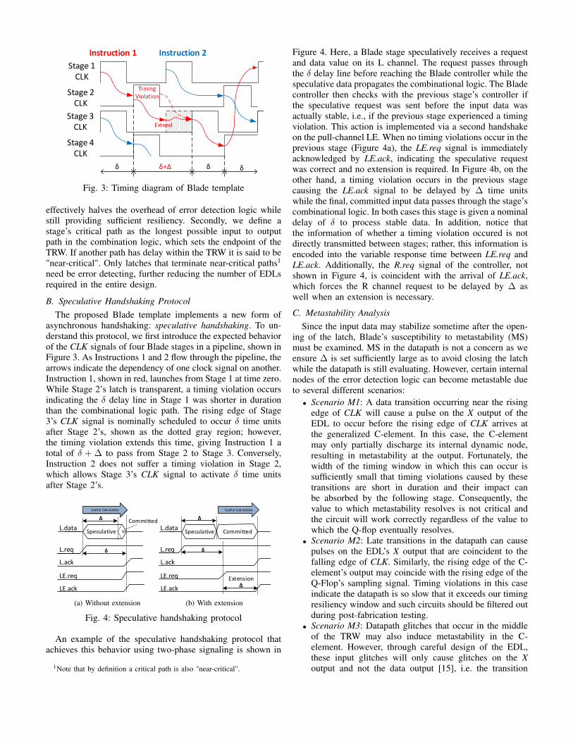
Fig. 4: Speculative handshaking protocol
An example of the speculative handshaking protocol thatachieves this behavior using two-phase signaling is shown in
1Note that by definition a critical path is also "near-critical".
Figure 4. Here, a Blade stage speculatively receives a requestand data value on its L channel. The request passes throughthe δ delay line before reaching the Blade controller while thespeculative data propagates the combinational logic. The Bladecontroller then checks with the previous stage’s controller ifthe speculative request was sent before the input data wasactually stable, i.e., if the previous stage experienced a timingviolation. This action is implemented via a second handshakeon the pull-channel LE. When no timing violations occur in theprevious stage (Figure 4a), the LE.req signal is immediatelyacknowledged by LE.ack, indicating the speculative requestwas correct and no extension is required. In Figure 4b, on theother hand, a timing violation occurs in the previous stagecausing the LE.ack signal to be delayed by ∆ time unitswhile the final, committed input data passes through the stage’scombinational logic. In both cases this stage is given a nominaldelay of δ to process stable data. In addition, notice thatthe information of whether a timing violation occured is notdirectly transmitted between stages; rather, this information isencoded into the variable response time between LE.req andLE.ack. Additionally, the R.req signal of the controller, notshown in Figure 4, is coincident with the arrival of LE.ack,which forces the R channel request to be delayed by ∆ aswell when an extension is necessary.
C. Metastability AnalysisSince the input data may stabilize sometime after the open-
ing of the latch, Blade’s susceptibility to metastability (MS)must be examined. MS in the datapath is not a concern as weensure ∆ is set sufficiently large as to avoid closing the latchwhile the datapath is still evaluating. However, certain internalnodes of the error detection logic can become metastable dueto several different scenarios:
• Scenario M1: A data transition occurring near the risingedge of CLK will cause a pulse on the X output of theEDL to occur before the rising edge of CLK arrives atthe generalized C-element. In this case, the C-elementmay only partially discharge its internal dynamic node,resulting in metastability at the output. Fortunately, thewidth of the timing window in which this can occur issufficiently small that timing violations caused by thesetransitions are short in duration and their impact canbe absorbed by the following stage. Consequently, thevalue to which metastability resolves is not critical andthe circuit will work correctly regardless of the value towhich the Q-flop eventually resolves.
• Scenario M2: Late transitions in the datapath can causepulses on the EDL’s X output that are coincident to thefalling edge of CLK. Similarly, the rising edge of the C-element’s output may coincide with the rising edge of theQ-Flop’s sampling signal. Timing violations in this caseindicate the datapath is so slow that it exceeds our timingresiliency window and such circuits should be filtered outduring post-fabrication testing.
• Scenario M3: Datapath glitches that occur in the middleof the TRW may also induce metastability in the C-element. However, through careful design of the EDL,these input glitches will only cause glitches on the Xoutput and not the data output [15], i.e. the transition
detector is more sensitive to glitches than the data latchitself. Consequently, metastability in this scenario onlyaffects performance but not correctness, just as MS inScenario M1. Moreover, the probability of entering MScan be reduced by making the generalized C-elementmore sensitive to glitches than the transition detector.
In rare cases, the output of the Q-Flop will take an arbi-trarily long time to resolve due to internal MS. In a robustsynchronous design, similar resolution delays translate directlyinto increased margins or extra clock cycles and synchronizersto wait for this rare occurrence to resolve. However, due tothe asynchronous nature of our template, the Blade controllerwill gracefully wait for the metastable state to resolve beforeallowing the next stage to open its latch, effectively stallingthe stage and ensuring correct operation. This is a significantbenefit of asynchronous design which, to the best of ourknowledge, cannot be easily approximated in synchronousalternatives.
D. Blade ControllersThe Blade controller is implemented as a set of three
interacting Burst-Mode state machines [17] and synthesizedusing the tool 3D [18]. Figure 5 shows these state machinesfor pipeline stages with EDLs. Note that intermediate signalsgoL, goR, and goD are communication signals between thethree individual state machines, and signals delay, edi, andedo are used to add the ∆ delay line into the controller. Forsimplicity, the delay line is duplicated between CLK→delayand edo→edi. Consolidating these to a single delay line is leftas future work.
We have extended this controller to a token version, whichgenerates an output request after reset, as well as simplifiedversions for stages without error detection logic, creating fourdistinct Blade controllers. We added reset to the unmappednetlists and manually mapped them to our 28nm library ofgates. For all cases, the implicit fundamental mode timingassumption [17] was validated using a simulation environmentwith random environmental delays.
E. Timing ConstraintsThe datapath in Blade most closely resembles a standard
time borrowing design [19]. However, the introduction of error
tX,pd tX,pwtCE,pd +tOR,pd +tQF,setup
tX,pd
CLK
X
D
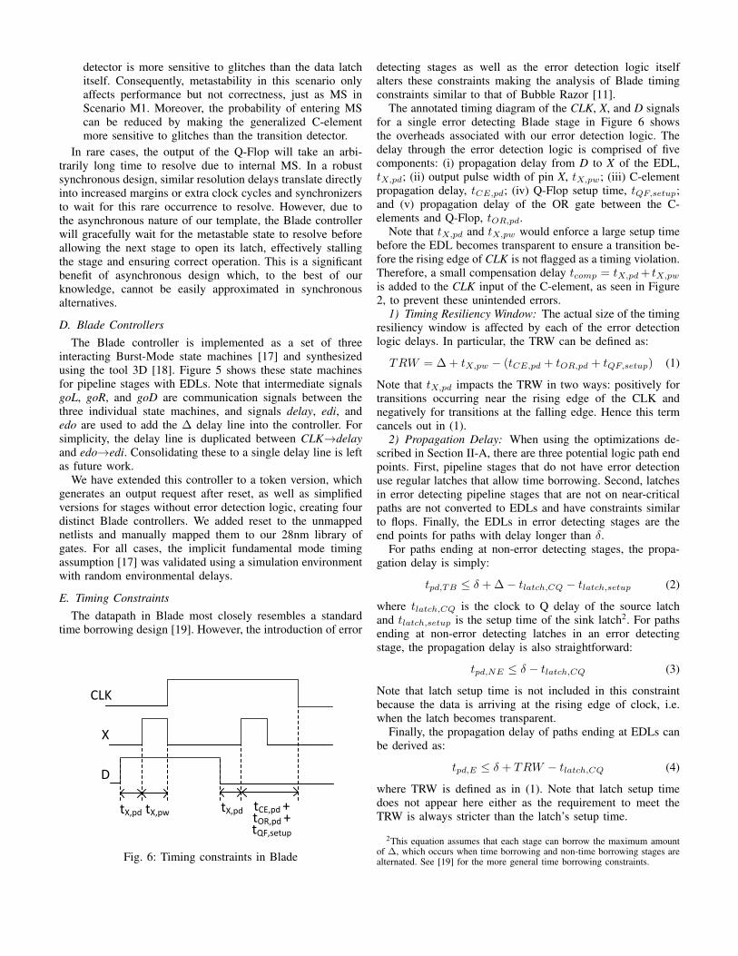
Fig. 6: Timing constraints in Blade
detecting stages as well as the error detection logic itselfalters these constraints making the analysis of Blade timingconstraints similar to that of Bubble Razor [11].
The annotated timing diagram of the CLK, X, and D signalsfor a single error detecting Blade stage in Figure 6 showsthe overheads associated with our error detection logic. Thedelay through the error detection logic is comprised of fivecomponents: (i) propagation delay from D to X of the EDL,tX,pd; (ii) output pulse width of pin X, tX,pw; (iii) C-elementpropagation delay, tCE,pd; (iv) Q-Flop setup time, tQF,setup;and (v) propagation delay of the OR gate between the C-elements and Q-Flop, tOR,pd.
Note that tX,pd and tX,pw would enforce a large setup timebefore the EDL becomes transparent to ensure a transition be-fore the rising edge of CLK is not flagged as a timing violation.Therefore, a small compensation delay tcomp = tX,pd + tX,pw
is added to the CLK input of the C-element, as seen in Figure2, to prevent these unintended errors.
1) Timing Resiliency Window: The actual size of the timingresiliency window is affected by each of the error detectionlogic delays. In particular, the TRW can be defined as:
TRW = ∆ + tX,pw − (tCE,pd + tOR,pd + tQF,setup) (1)
Note that tX,pd impacts the TRW in two ways: positively fortransitions occurring near the rising edge of the CLK andnegatively for transitions at the falling edge. Hence this termcancels out in (1).
2) Propagation Delay: When using the optimizations de-scribed in Section II-A, there are three potential logic path endpoints. First, pipeline stages that do not have error detectionuse regular latches that allow time borrowing. Second, latchesin error detecting pipeline stages that are not on near-criticalpaths are not converted to EDLs and have constraints similarto flops. Finally, the EDLs in error detecting stages are theend points for paths with delay longer than δ.
For paths ending at non-error detecting stages, the propa-gation delay is simply:
tpd,TB ≤ δ + ∆− tlatch,CQ − tlatch,setup (2)
where tlatch,CQ is the clock to Q delay of the source latchand tlatch,setup is the setup time of the sink latch2. For pathsending at non-error detecting latches in an error detectingstage, the propagation delay is also straightforward:
tpd,NE ≤ δ − tlatch,CQ (3)
Note that latch setup time is not included in this constraintbecause the data is arriving at the rising edge of clock, i.e.when the latch becomes transparent.
Finally, the propagation delay of paths ending at EDLs canbe derived as:
tpd,E ≤ δ + TRW − tlatch,CQ (4)
where TRW is defined as in (1). Note that latch setup timedoes not appear here either as the requirement to meet theTRW is always stricter than the latch’s setup time.
2This equation assumes that each stage can borrow the maximum amountof ∆, which occurs when time borrowing and non-time borrowing stages arealternated. See [19] for the more general time borrowing constraints.

goD+ / CLK+
delay+ /goL+ Sample+ CLK-
goD- delay- /Sample-
goD+ / CLK+
delay+ /goL- Sample+ CLK-
goD- delay- /Sample-
RE.req+ Err[1]+ /edo+
edi+ /RE.ack+ goD- edo-
Err[1]- edi- / Err[0]- /
RE.req+ Err[0]+ /RE.ack+ goD-
L.req+ / LE.req+
LE.ack+ / goR+
goL+ / Lack+ L.req- / LE.req-
LE.ack- / goR-
goL- / L.ack-
RE.req- Err[1]+ /edo+
Err[1]- edi- / Err[0]- /
RE.req- Err[0]+ /RE.ack- goD-
edi+ /RE.ack- goD- edo-
goR+ R.ack- / goD+ R.req+
goR- R.ack+ / goD+ R.req-
goL
goR
goD
L.req
L.ackLE.reqLE.ack
R.reqR.ack
RE.reqRE.ack
Err[1] Err[0]Sample CLK
δ
Δ
Δ edo
edi
delay
Blade Controller
Fig. 5: Burst-mode state machines for Blade controller with error detection
3) Contamination Delay: The Blade controller enforcesa condition that latches of neighboring stages cannot betransparent at the same time, which provides significant holdtime margin. When including the clock tree delays, tCLK,pd,the hold time constraint between two stages is:
tcd ≥ (tCLKR,pd − tCLKL,pd)− tack_to_clk (5)
where L and R represent two neighboring stages and tack_to_clkis the delay from R’s controller generating an acknowledge-ment signal to L’s controller raising its clock signal. Inpractice, tack_to_clk is around 4 gate delays, making tcd smallor even negative for balanced local clock trees. This is incontrast to many resiliency schemes which exacerbate holdtime issues (e.g. [11]).
4) Hiding Handshaking Overhead: After a request is re-ceived at a Blade controller, a full two-phase handshake mustoccur on its LE channel to check if the previous stage suffereda timing violation. Even when no violations occur, this processtakes a non-zero amount of time, tEC , due to gate delaysin the two controllers. Fortunately, this delay can be hiddencompletely by shortening the stage to stage delay, δ, by tEC .If δ is not shortened, the circuit will still operate correctly butwith slower performance.
F. Maximum Timing Resiliency Window
To compute the maximum width of the timing resiliencywindow, TRWmax, we first define a few additional delays:
• tQF,pd : the nominal propagation delay from the sampleinput to the outputs of the Q-Flop without metastability.
• tET,pd : the maximum propagation delay of the AND andOR trees that collect the individual dual-rail error signalsfrom the Q-Flops.
To find TRWmax, it is also helpful to first define ∆max,the maximum clock pulse width for a Blade stage. Becauseopening the latch of one stage depends on checking if anerror occurred in a previous stage, ∆ cannot be equal to δ
and still achieve the expected cycle time including overheads.Therefore, ∆max is conservatively set as:
∆max = δ − tET,pd − tQF,pd − tErr[0]_to_clk (6)
where tErr[0]_to_clk is the internal controller delays fromreceiving Err[0] one controller to raising the clock signal inthe subsequent stage. Combining (1) and (6) we find:
TRWmax = δ − tET,pd − tQF,pd − tErr[0]_to_clk
+ tX,pw − (tCE,pd + tOR,pd + tQF,setup)(7)
In some cases, a large TRW may not be ideal and setting it to20-30% may be sufficient, as was done in [11]. In addition,reasonable estimates of tCE,pd and tQF,setup in a modernprocess are on the order of tens of ps. However, the magnitudeof tET,pd and tOR,pd depend on multiple factors, including thenumber of EDLs per stage and the degree to which the EDLsare amortized across Q-Flops. This presents an interestingoptimization problem in which reducing the number of EDLsmay also maximize the potential performance of the design.
III. CASE STUDY: PLASMA 3-STAGE CPU
A. Automatic Translation to Blade Template
An automated flow to convert single CLK domain syn-chronous RTL designs to asynchronous Blade using indus-try standard tools, including DesignCompiler and PrimeTimefrom Synopsys (for synthesis and STA) and NC-Sim from Ca-dence (for simulation), was developed to analyze the benefitsof the proposed template on a 3-stage version of Plasma [13], aMIPS OpenCore CPU, targeting a 28nm FD-SOI technology.The flow consists of various Tcl and shell scripts, a libraryof custom cells, and a Verilog co-simulation environmentfor verification and analysis that are wrapped in a Makefilesystem, which provides multiple configuration knobs to controlthe synthesized frequency, TRW, compensation for overheads,and other aspects of the design. The flow has 5 main steps:

Final Blade Netlist
Latch to EDL Conversion +Controller Insertion
Retiming
FF to Latch Conversion
SynchLibrary
CustomBladeCells
Synchronous Synthesis
RTL Specification
Resynthesis
FF-Based Design
Master-Slave Latch-Based Design
Balanced Latch-Based Design
Resiliency-Aware Optimized Latch-Based Design
Fig. 7: Blade design flow
1) Synchronous Synthesis: The synchronous RTL is syn-thesized to a flip-flop (FF) based design at a given clockfrequency with preset I/O delays and output load values.
2) FF to Latch Conversion: The FFs are converted tomaster-slave latches by synthesizing the design using afake library of standardized D-Flip Flops (DFFs) that canbe easily mapped to standard-cell latches.
3) Latch Retiming: The latch-based netlist is then retimedusing a target TRW that defines the maximum timeborrowing allowed, where the combined path delay con-straint of any two stages equals the given clock period.
4) Resynthesis: The retimed netlist is then resynthesized tooptimize the expected area and performance of the finalresilient netlist, as will be described in Section III-C.
5) Blade Conversion: The resynthesized latch-based netlistis then converted to the Blade template by removingclock trees and replacing them with Blade controllers.The control logic, delay lines, and error detection logicare also inserted to create a final Blade netlist.
The final Blade netlist is validated via co-simulation with thesynchronous netlist from step 1 to verify correct operation andmeasure performance. In particular, to verify correct operationthe stream of inputs is forked to both the synchronous andBlade netlists and the stream of outputs is compared.
B. Handling Macros
In many designs there may be logic blocks that are eitherimplemented using hard macros or would be problematicto convert to the Blade template directly. Therefore, it isbeneficial to capture errors at the inputs to these cells andensure the timing for the macro is satisfied at the ideal targetclock frequency, i.e. the given clock period minus the TRW.Fortunately, an important advantage of asynchronous designis that we can add new pipeline stages to the design withoutchanging functionality. For Blade, we take advantage of thisfeature by adding an error-detecting pipeline stage at theinput of the macro controlled by a non-token-buffer pipelinecontroller. These controllers only pass tokens through thesystem; unlike token controllers, they do not generate tokenson reset. Therefore, the functional behavior of the design is
unchanged. In synchronous designs, this would not be possiblewithout major architectural modifications as adding a pipelinestage changes the functionality greatly.
As an example of this process, the Plasma CPU containsa 32 entry register file (RF) that can be implemented usinga memory generator or synthesized directly as 32 flip-flopsper register. It is not uncommon for either the input or outputof the RF to be on a critical path in the CPU; however, it isoften the case that the majority of this critical delay occursoutside of the macro boundary (e.g. an ALU’s result beingstored into the RF). With Blade, if a near-critical path endsat the RF, all internal registers would need to be converted toEDLs, resulting in large area overheads. But we can exploitthe fact that the decoding logic inside the RF macro is quickin comparison to the rest of the input path by adding a non-token Blade stage on the data and address inputs to the RF. Wetherefore achieve the same resiliency benefits while reducingthe number of EDLs drastically without changing the macroitself; for a 32-bit RF, only 37 EDLs are required when placedat the input (32 for data, 5 for address) instead of 1024 whenthe internal flops are converted to EDLs. The nominal datapathdelay from the added error detecting Blade stage, through theRF, and to the subsequent Blade stage must be faster than theideal target frequency for this method to be effective, whichwas easily met in our case.
C. ResynthesisEach EDL adds overhead in timing and area in multiple
ways: i) the EDL itself is larger than a latch; ii) the numberof C-elements and Q-Flops increase; and iii) the size of theOR/AND trees needed to combine error signals also increases.Therefore, it is desirable to minimize the number of EDLswhile maintaining both the robustness to timing violations andthe expected performance increases. One method to achievethese goals is through resynthesis. The retiming step of theBlade design flow generates a report of latches that shouldbe converted to EDLs, i.e. all latches that are on a near-critical path, such that the static timing analysis indicates atiming violation would occur when running at the ideal targetfrequency. Constraining the delay to one of these latches tobe no greater than the target frequency and resynthesizing thedesign would therefore remove the selected latch from theEDL report, allowing it to be implemented using a standard
−40 −20 0 20
−2
−1
0
1
2
Change in Error Rate (%)
Ch
an
ge
in A
rea
(%
)
Fig. 8: Resynthesis to improve area and decrease error rate
latch rather than an EDL. Although the combinational areamay increase due to tighter constraints on certain paths, thisoverhead can be offset if multiple latches that were slatedto become EDLs are no longer on near-critical paths aswell. Unfortunately, the high degree of shared paths in thecombinational logic makes it challenging to estimate the thereduction in EDLs, i.e. constraining one latch may also speedup shared paths to many other latches. Moreover, the reductionof EDLs combined with faster combinational logic may leadto a reduced frequency of timing violations during simulation,which affects the maximum performance of the circuit.
Without reliable methods of estimating these two effects, itis difficult to know a priori which latch(es) in the EDL reportto further constrain; therefore, a brute-force approach in whichall latches marked EDL are tested one by one is employed tofind a suitable candidate latch. Figure 8 shows the results ofthis approach on the Plasma CPU, with a given frequency of666MHz and a target frequency of 952MHz. After retiming,there 456 latches required to be converted to EDLs. A maxdelay constraint equal to the target clock period was placedon each latch separately to ensure no timing violations wouldoccur. Then the netlist was resynthesized, converted to Blade,and simulated in the co-simulation environment to obtain boththe post-conversion area and error rate, i.e. the frequency oftiming violations averaged over the entire simulation. The bestpoint, highlighted in red in Figure 8, yields a 27% decreasein number of EDLs with a 1.79% decrease in overall area,and 39% improvement in error rate. Note that the potentialbenefits of this resynthesis approach will depend heavily on theinitial starting frequency, i.e. a design that is already heavilyconstrained cannot easily be constrained further to achieve areaand performance benefits.
D. Area and Performance ComparisonsUsing the flow described in Section III-A, Plasma was
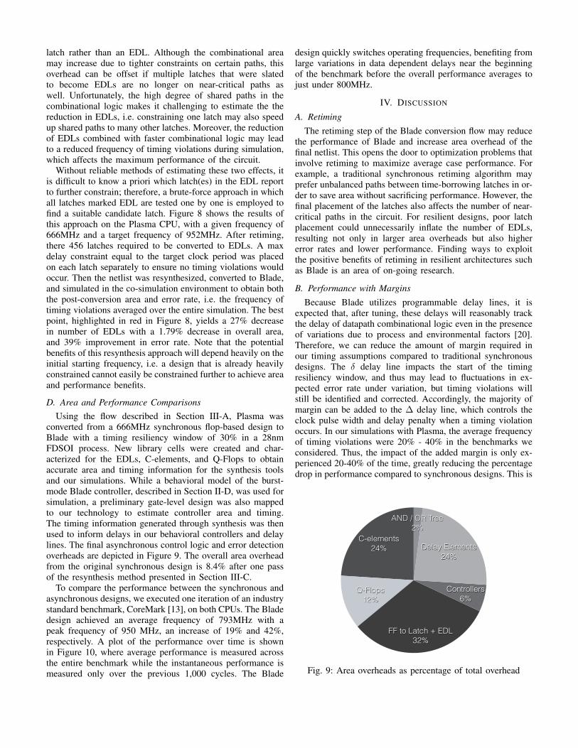
converted from a 666MHz synchronous flop-based design toBlade with a timing resiliency window of 30% in a 28nmFDSOI process. New library cells were created and char-acterized for the EDLs, C-elements, and Q-Flops to obtainaccurate area and timing information for the synthesis toolsand our simulations. While a behavioral model of the burst-mode Blade controller, described in Section II-D, was used forsimulation, a preliminary gate-level design was also mappedto our technology to estimate controller area and timing.The timing information generated through synthesis was thenused to inform delays in our behavioral controllers and delaylines. The final asynchronous control logic and error detectionoverheads are depicted in Figure 9. The overall area overheadfrom the original synchronous design is 8.4% after one passof the resynthesis method presented in Section III-C.
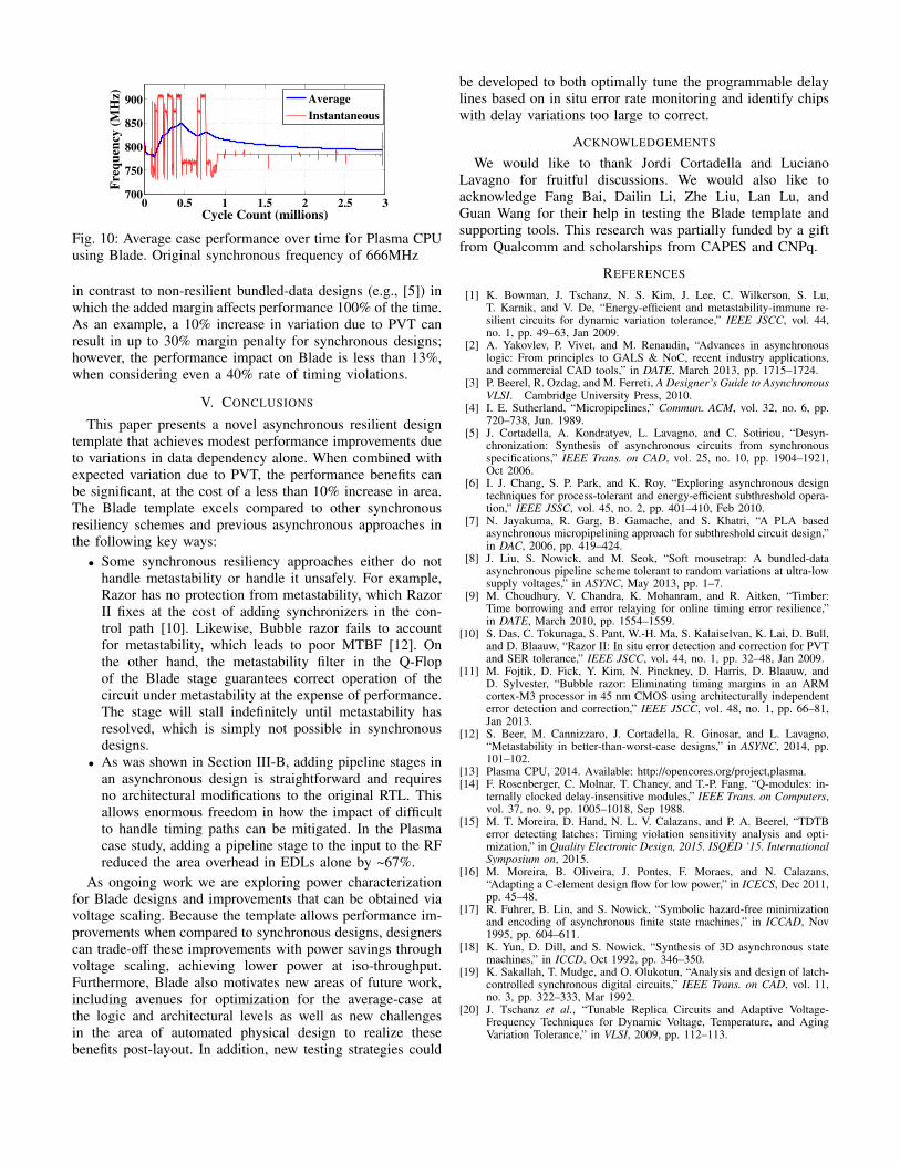
To compare the performance between the synchronous andasynchronous designs, we executed one iteration of an industrystandard benchmark, CoreMark [13], on both CPUs. The Bladedesign achieved an average frequency of 793MHz with apeak frequency of 950 MHz, an increase of 19% and 42%,respectively. A plot of the performance over time is shownin Figure 10, where average performance is measured acrossthe entire benchmark while the instantaneous performance ismeasured only over the previous 1,000 cycles. The Blade
design quickly switches operating frequencies, benefiting fromlarge variations in data dependent delays near the beginningof the benchmark before the overall performance averages tojust under 800MHz.
IV. DISCUSSION
A. RetimingThe retiming step of the Blade conversion flow may reduce
the performance of Blade and increase area overhead of thefinal netlist. This opens the door to optimization problems thatinvolve retiming to maximize average case performance. Forexample, a traditional synchronous retiming algorithm mayprefer unbalanced paths between time-borrowing latches in or-der to save area without sacrificing performance. However, thefinal placement of the latches also affects the number of near-critical paths in the circuit. For resilient designs, poor latchplacement could unnecessarily inflate the number of EDLs,resulting not only in larger area overheads but also highererror rates and lower performance. Finding ways to exploitthe positive benefits of retiming in resilient architectures suchas Blade is an area of on-going research.
B. Performance with MarginsBecause Blade utilizes programmable delay lines, it is
expected that, after tuning, these delays will reasonably trackthe delay of datapath combinational logic even in the presenceof variations due to process and environmental factors [20].Therefore, we can reduce the amount of margin required inour timing assumptions compared to traditional synchronousdesigns. The δ delay line impacts the start of the timingresiliency window, and thus may lead to fluctuations in ex-pected error rate under variation, but timing violations willstill be identified and corrected. Accordingly, the majority ofmargin can be added to the ∆ delay line, which controls theclock pulse width and delay penalty when a timing violationoccurs. In our simulations with Plasma, the average frequencyof timing violations were 20% - 40% in the benchmarks weconsidered. Thus, the impact of the added margin is only ex-perienced 20-40% of the time, greatly reducing the percentagedrop in performance compared to synchronous designs. This is
C-elements 24%
Q-Flops 12%
FF to Latch + EDL 32%
Controllers 6%
Delay Elements 24%
AND / OR Tree 2%
Fig. 9: Area overheads as percentage of total overhead
0 0.5 1 1.5 2 2.5 3700
750
800
850
900
Cycle Count (millions)
Fre
qu
ency
(M
Hz)
Average
Instantaneous
Fig. 10: Average case performance over time for Plasma CPUusing Blade. Original synchronous frequency of 666MHz
in contrast to non-resilient bundled-data designs (e.g., [5]) inwhich the added margin affects performance 100% of the time.As an example, a 10% increase in variation due to PVT canresult in up to 30% margin penalty for synchronous designs;however, the performance impact on Blade is less than 13%,when considering even a 40% rate of timing violations.
V. CONCLUSIONS
This paper presents a novel asynchronous resilient designtemplate that achieves modest performance improvements dueto variations in data dependency alone. When combined withexpected variation due to PVT, the performance benefits canbe significant, at the cost of a less than 10% increase in area.The Blade template excels compared to other synchronousresiliency schemes and previous asynchronous approaches inthe following key ways:
• Some synchronous resiliency approaches either do nothandle metastability or handle it unsafely. For example,Razor has no protection from metastability, which RazorII fixes at the cost of adding synchronizers in the con-trol path [10]. Likewise, Bubble razor fails to accountfor metastability, which leads to poor MTBF [12]. Onthe other hand, the metastability filter in the Q-Flopof the Blade stage guarantees correct operation of thecircuit under metastability at the expense of performance.The stage will stall indefinitely until metastability hasresolved, which is simply not possible in synchronousdesigns.
• As was shown in Section III-B, adding pipeline stages inan asynchronous design is straightforward and requiresno architectural modifications to the original RTL. Thisallows enormous freedom in how the impact of difficultto handle timing paths can be mitigated. In the Plasmacase study, adding a pipeline stage to the input to the RFreduced the area overhead in EDLs alone by ~67%.
As ongoing work we are exploring power characterizationfor Blade designs and improvements that can be obtained viavoltage scaling. Because the template allows performance im-provements when compared to synchronous designs, designerscan trade-off these improvements with power savings throughvoltage scaling, achieving lower power at iso-throughput.Furthermore, Blade also motivates new areas of future work,including avenues for optimization for the average-case atthe logic and architectural levels as well as new challengesin the area of automated physical design to realize thesebenefits post-layout. In addition, new testing strategies could
be developed to both optimally tune the programmable delaylines based on in situ error rate monitoring and identify chipswith delay variations too large to correct.
ACKNOWLEDGEMENTS
We would like to thank Jordi Cortadella and LucianoLavagno for fruitful discussions. We would also like toacknowledge Fang Bai, Dailin Li, Zhe Liu, Lan Lu, andGuan Wang for their help in testing the Blade template andsupporting tools. This research was partially funded by a giftfrom Qualcomm and scholarships from CAPES and CNPq.
REFERENCES
[1] K. Bowman, J. Tschanz, N. S. Kim, J. Lee, C. Wilkerson, S. Lu,T. Karnik, and V. De, “Energy-efficient and metastability-immune re-silient circuits for dynamic variation tolerance,” IEEE JSCC, vol. 44,no. 1, pp. 49–63, Jan 2009.
[2] A. Yakovlev, P. Vivet, and M. Renaudin, “Advances in asynchronouslogic: From principles to GALS & NoC, recent industry applications,and commercial CAD tools,” in DATE, March 2013, pp. 1715–1724.
[3] P. Beerel, R. Ozdag, and M. Ferreti, A Designer’s Guide to AsynchronousVLSI. Cambridge University Press, 2010.
[4] I. E. Sutherland, “Micropipelines,” Commun. ACM, vol. 32, no. 6, pp.720–738, Jun. 1989.
[5] J. Cortadella, A. Kondratyev, L. Lavagno, and C. Sotiriou, “Desyn-chronization: Synthesis of asynchronous circuits from synchronousspecifications,” IEEE Trans. on CAD, vol. 25, no. 10, pp. 1904–1921,Oct 2006.
[6] I. J. Chang, S. P. Park, and K. Roy, “Exploring asynchronous designtechniques for process-tolerant and energy-efficient subthreshold opera-tion,” IEEE JSSC, vol. 45, no. 2, pp. 401–410, Feb 2010.
[7] N. Jayakuma, R. Garg, B. Gamache, and S. Khatri, “A PLA basedasynchronous micropipelining approach for subthreshold circuit design,”in DAC, 2006, pp. 419–424.
[8] J. Liu, S. Nowick, and M. Seok, “Soft mousetrap: A bundled-dataasynchronous pipeline scheme tolerant to random variations at ultra-lowsupply voltages,” in ASYNC, May 2013, pp. 1–7.
[9] M. Choudhury, V. Chandra, K. Mohanram, and R. Aitken, “Timber:Time borrowing and error relaying for online timing error resilience,”in DATE, March 2010, pp. 1554–1559.
[10] S. Das, C. Tokunaga, S. Pant, W.-H. Ma, S. Kalaiselvan, K. Lai, D. Bull,and D. Blaauw, “Razor II: In situ error detection and correction for PVTand SER tolerance,” IEEE JSCC, vol. 44, no. 1, pp. 32–48, Jan 2009.
[11] M. Fojtik, D. Fick, Y. Kim, N. Pinckney, D. Harris, D. Blaauw, andD. Sylvester, “Bubble razor: Eliminating timing margins in an ARMcortex-M3 processor in 45 nm CMOS using architecturally independenterror detection and correction,” IEEE JSCC, vol. 48, no. 1, pp. 66–81,Jan 2013.
[12] S. Beer, M. Cannizzaro, J. Cortadella, R. Ginosar, and L. Lavagno,“Metastability in better-than-worst-case designs,” in ASYNC, 2014, pp.101–102.
[13] Plasma CPU, 2014. Available: http://opencores.org/project,plasma.[14] F. Rosenberger, C. Molnar, T. Chaney, and T.-P. Fang, “Q-modules: in-
ternally clocked delay-insensitive modules,” IEEE Trans. on Computers,vol. 37, no. 9, pp. 1005–1018, Sep 1988.
[15] M. T. Moreira, D. Hand, N. L. V. Calazans, and P. A. Beerel, “TDTBerror detecting latches: Timing violation sensitivity analysis and opti-mization,” in Quality Electronic Design, 2015. ISQED ’15. InternationalSymposium on, 2015.
[16] M. Moreira, B. Oliveira, J. Pontes, F. Moraes, and N. Calazans,“Adapting a C-element design flow for low power,” in ICECS, Dec 2011,pp. 45–48.
[17] R. Fuhrer, B. Lin, and S. Nowick, “Symbolic hazard-free minimizationand encoding of asynchronous finite state machines,” in ICCAD, Nov1995, pp. 604–611.
[18] K. Yun, D. Dill, and S. Nowick, “Synthesis of 3D asynchronous statemachines,” in ICCD, Oct 1992, pp. 346–350.
[19] K. Sakallah, T. Mudge, and O. Olukotun, “Analysis and design of latch-controlled synchronous digital circuits,” IEEE Trans. on CAD, vol. 11,no. 3, pp. 322–333, Mar 1992.
[20] J. Tschanz et al., “Tunable Replica Circuits and Adaptive Voltage-Frequency Techniques for Dynamic Voltage, Temperature, and AgingVariation Tolerance,” in VLSI, 2009, pp. 112–113.