Embed Size (px)
Citation preview
Blake Davis: Electrical EngineeringLuke Haberkern: Electrical and Computer EngineeringBrian Hacsi: Electrical and Computer EngineeringChris Kircher: Electrical and Computer Engineering
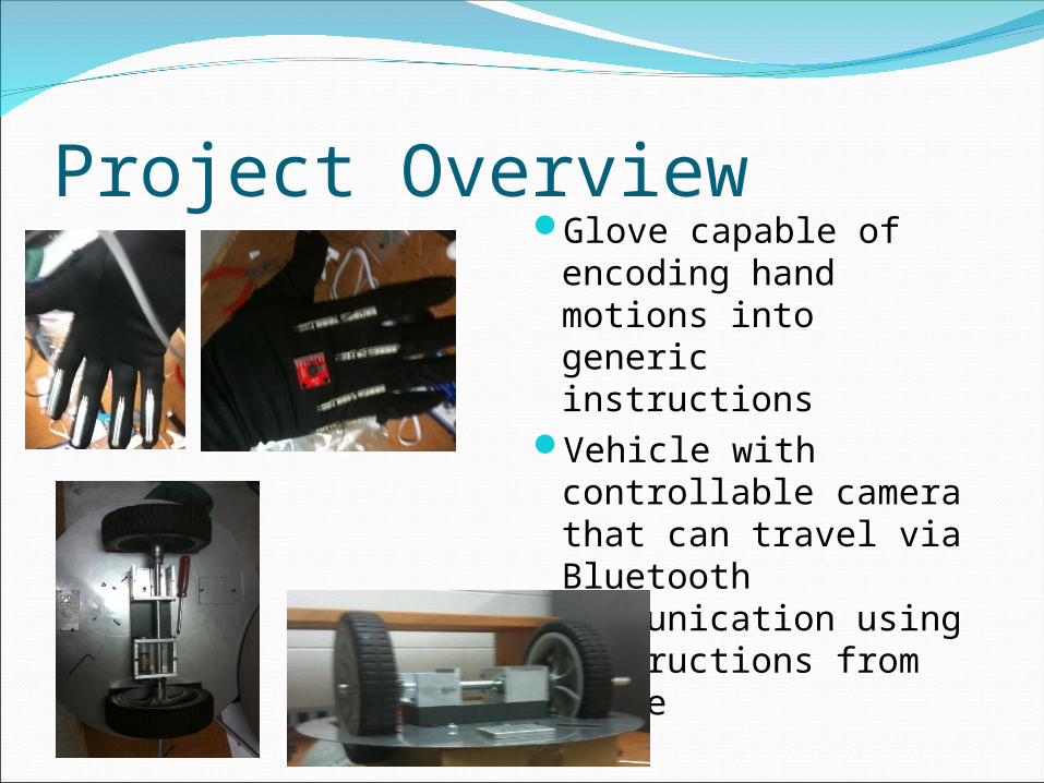
Project OverviewGlove capable of
encoding hand motions into generic instructions
Vehicle with controllable camera that can travel via Bluetooth communication using instructions from glove
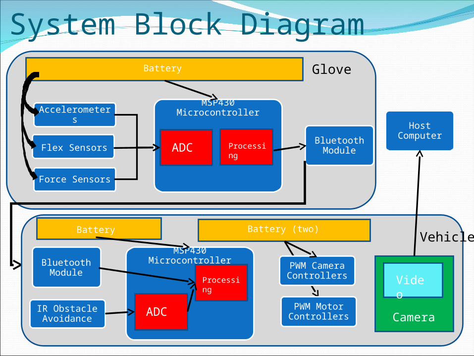
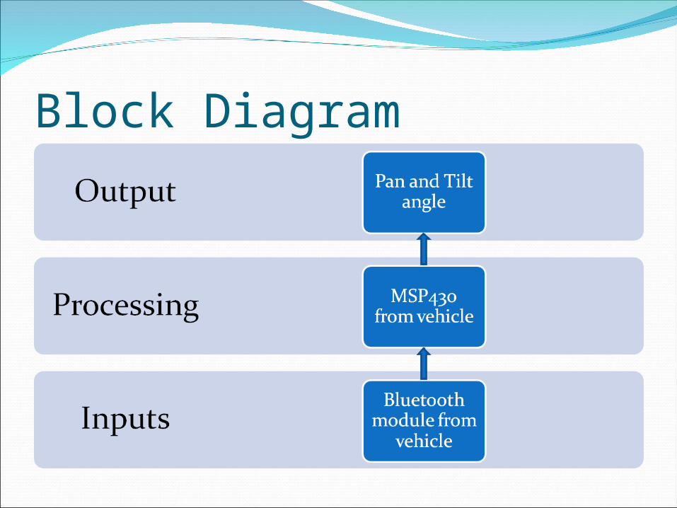
System Block Diagram
MSP430 MicrocontrollerAccelerometers
Flex Sensors
Force Sensors
Host ComputerBluetooth
Module
Glove
ADC Processing
Battery
PWM Motor Controllers
IR Obstacle Avoidance
PWM Camera Controllers
Bluetooth Module
VehicleMSP430 Microcontroller
Processing
ADC Camera
Video
Battery (two)Battery
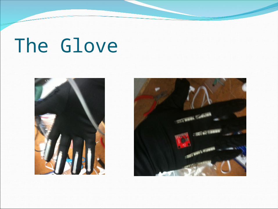
The Glove
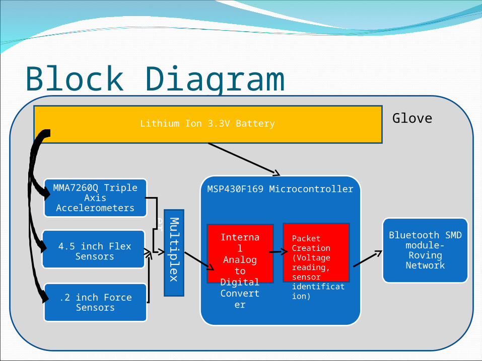
Block Diagram
MSP430F169 MicrocontrollerMMA7260Q Triple Axis
Accelerometers
4.5 inch Flex Sensors
.2 inch Force Sensors
Bluetooth SMD module- Roving
Network
Glove
Internal Analog
to Digital
Converter
Packet Creation (Voltage reading, sensor identification)
Lithium Ion 3.3V Battery
Mu
ltiple
xer
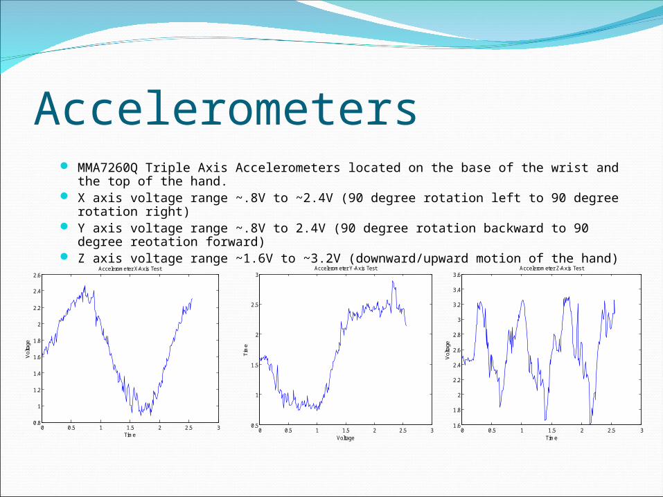
Accelerometers MMA7260Q Triple Axis Accelerometers located on the base of the wrist and the top
of the hand. X axis voltage range ~.8V to ~2.4V (90 degree rotation left to 90 degree rotation
right) Y axis voltage range ~.8V to 2.4V (90 degree rotation backward to 90 degree
reotation forward) Z axis voltage range ~1.6V to ~3.2V (downward/upward motion of the hand)
0 0.5 1 1.5 2 2.5 30.8
1
1.2
1.4
1.6
1.8
2
2.2
2.4
2.6Accelerometer X-Axis Test
Vol
tage
Time0 0.5 1 1.5 2 2.5 3
0.5
1
1.5
2
2.5
3Accelerometer Y-Axis Test
Voltage
Tim
e
0 0.5 1 1.5 2 2.5 31.6
1.8
2
2.2
2.4
2.6
2.8
3
3.2
3.4
3.6Accelerometer Z-Axis Test
Vol
tage
Time
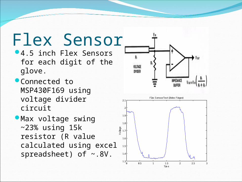
Flex Sensors4.5 inch Flex Sensors
for each digit of the glove.
Connected to MSP430F169 using voltage divider circuit
Max voltage swing ~23% using 15k resistor (R value calculated using excel spreadsheet) of ~.8V.
0 0.5 1 1.5 2 2.5 31.3
1.4
1.5
1.6
1.7
1.8
1.9
2
2.1Flex Sensor Test (Index Finger)
Time
Vol
tage
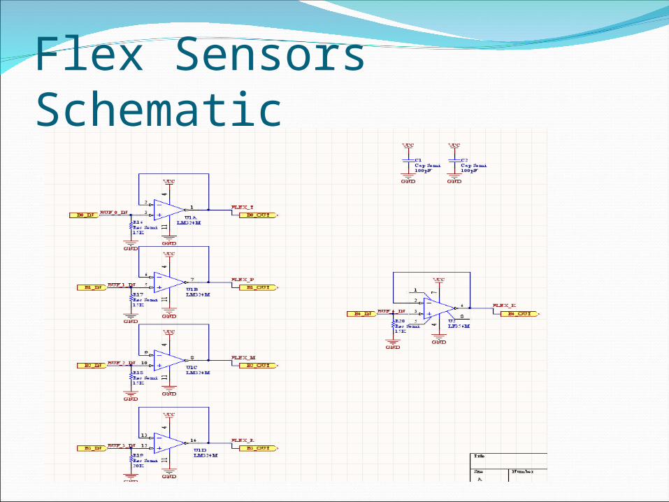
Flex Sensors Schematic
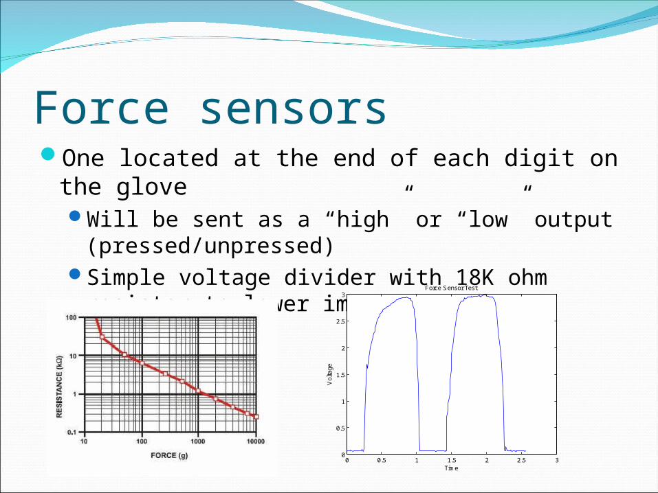
Force sensorsOne located at the end of each digit on the
gloveWill be sent as a “high” or “low” output
(pressed/unpressed)Simple voltage divider with 18K ohm resistor
to lower impedance
0 0.5 1 1.5 2 2.5 30
0.5
1
1.5
2
2.5
3Force Sensor Test
Time
Vol
tage
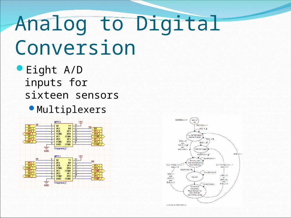
Analog to Digital ConversionEight A/D inputs
for sixteen sensorsMultiplexers
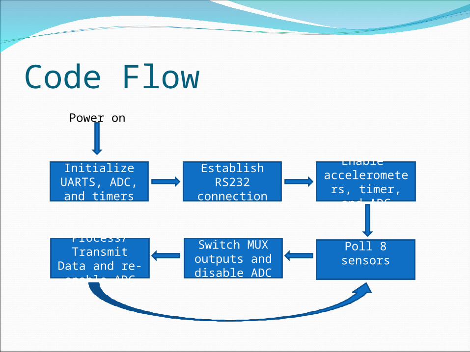
Code Flow
Initialize UARTS, ADC,
and timers
Establish RS232
connection
Enable accelerometers, timer, and
ADC
Poll 8 sensorsProcess/
Transmit Data and re-enable
ADC
Switch MUX outputs and disable ADC
Power on
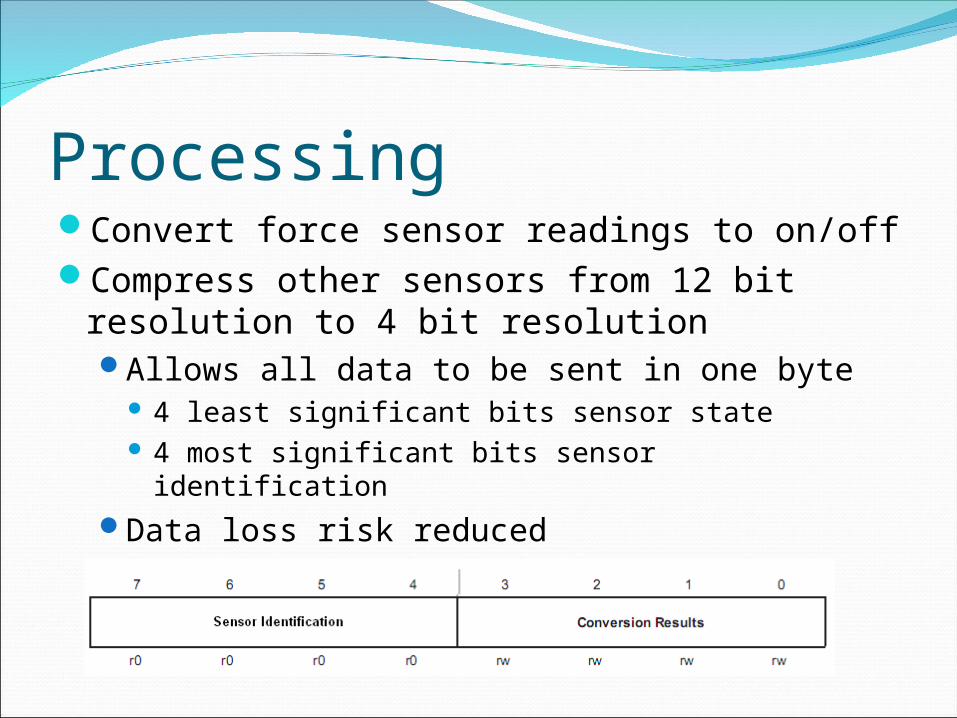
ProcessingConvert force sensor readings to on/offCompress other sensors from 12 bit
resolution to 4 bit resolutionAllows all data to be sent in one byte
4 least significant bits sensor state 4 most significant bits sensor identification
Data loss risk reduced

Data Transfer—RS232/BluetoothInitially RS232 wired
data transferBetween Milestone 1
and 2, transition to Bluetooth networking
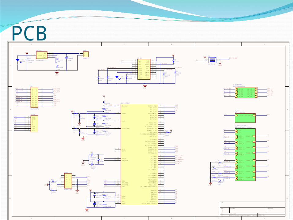
PCB
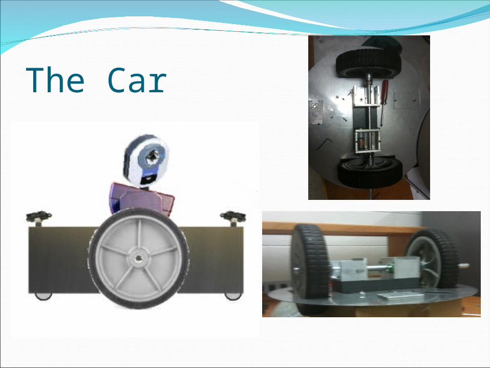
The Car
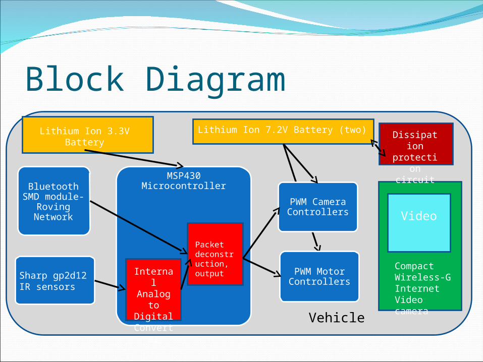
Block Diagram
PWM Motor Controllers
Sharp gp2d12 IR sensors
PWM Camera Controllers
Bluetooth SMD
module- Roving
Network
Vehicle
MSP430 Microcontroller
Packet deconstruction, output Internal
Analog to
Digital Converte
r
Compact Wireless-G Internet Video camera
Video
Lithium Ion 7.2V Battery (two)Lithium Ion 3.3V Battery Dissipation
protection circuit
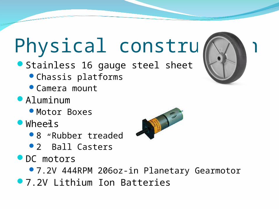
Physical constructionStainless 16 gauge steel sheet metal
Chassis platformsCamera mount
AluminumMotor Boxes
Wheels8” Rubber treaded2” Ball Casters
DC motors7.2V 444RPM 206oz-in Planetary Gearmotor
7.2V Lithium Ion Batteries
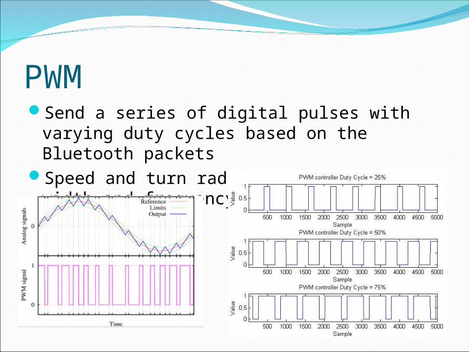
PWMSend a series of digital pulses with varying
duty cycles based on the Bluetooth packetsSpeed and turn radius determined by the
width and frequency of each pulse
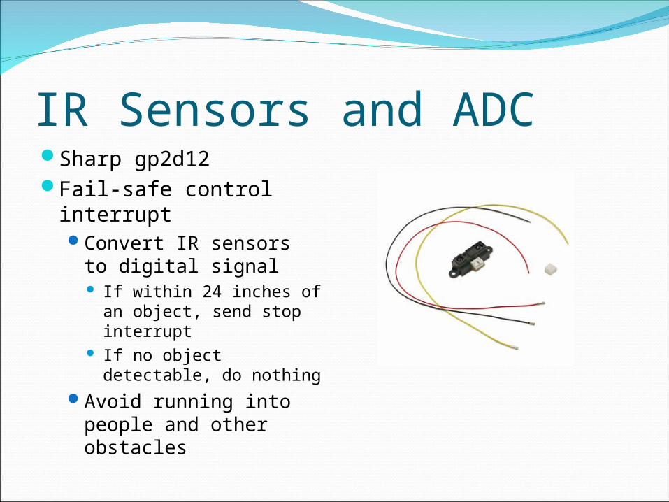
IR Sensors and ADCSharp gp2d12Fail-safe control
interruptConvert IR sensors to
digital signal If within 24 inches of an
object, send stop interrupt
If no object detectable, do nothing
Avoid running into people and other obstacles
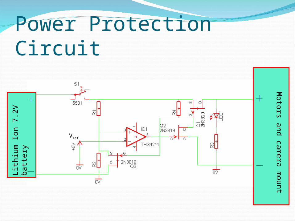
Power Protection Circuit
Moto
rs an
d ca
mera
mou
nt
Lit
hiu
m I
on
7.2
V b
att
ery
Vref
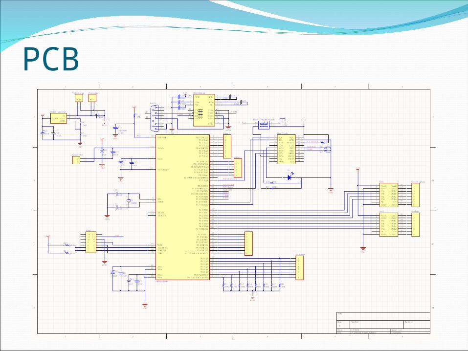
PCB
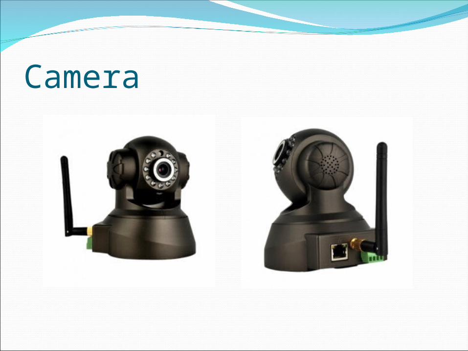
Camera
Block Diagram
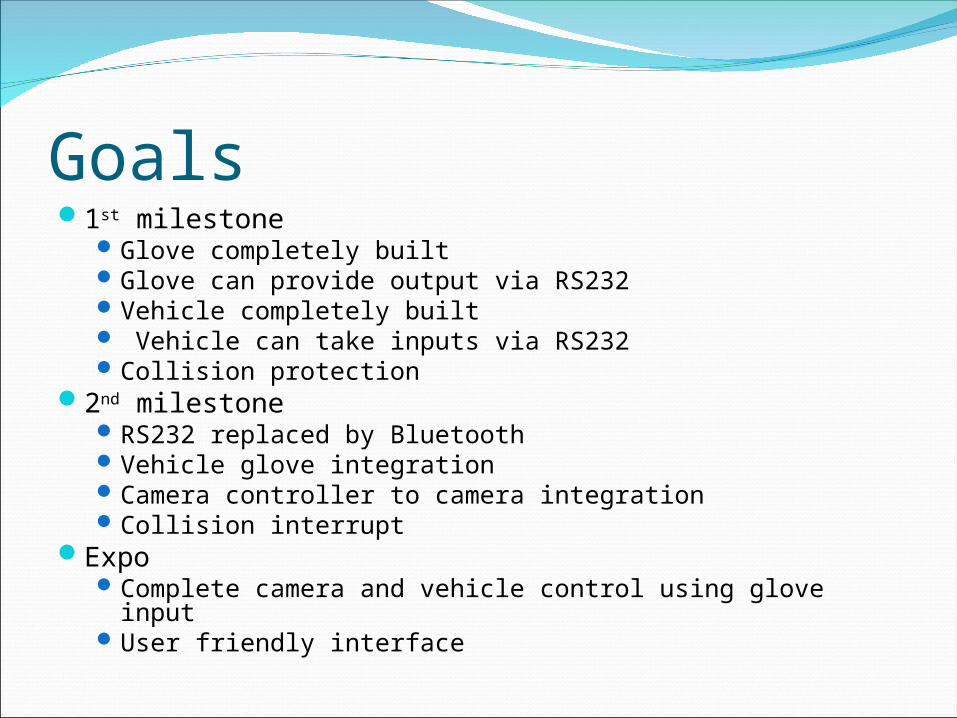
Goals1st milestone
Glove completely builtGlove can provide output via RS232Vehicle completely built Vehicle can take inputs via RS232Collision protection
2nd milestoneRS232 replaced by BluetoothVehicle glove integrationCamera controller to camera integrationCollision interrupt
ExpoComplete camera and vehicle control using glove inputUser friendly interface
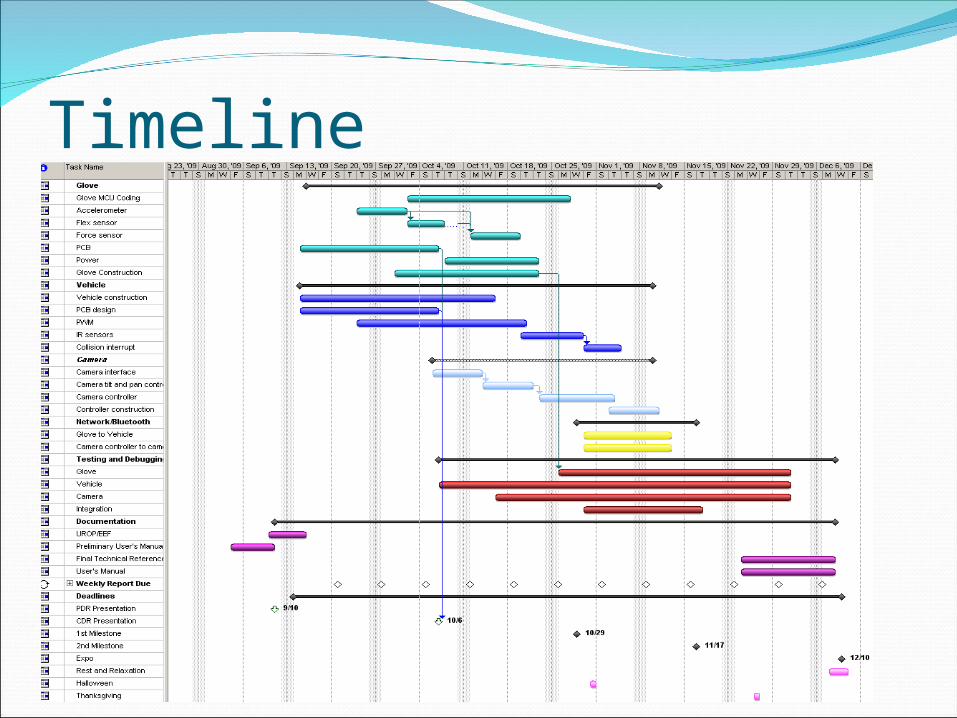
Timeline

Division of Labor Blake Chris Luke BrianGlove Glove MCU Coding X X Accelerometer X Flex sensor X Force sensor X PCB XPower X X Glove Construction X X Vehicle Vehicle MCU Coding X XVehicle construction X XPCB design XPWM X XIR sensors X XCamera Camera interface X Camera tilt and pan control X XCamera controller X X Controller construction X X Network/Bluetooth Glove to Vehicle X X X XCamera controller to camera X X X XTesting and Debugging Glove X X Vehicle X XCamera X X X XIntegration X X X XDocumentation UROP/EEF X X Preliminary User's Manual X XFinal Technical Reference X X X XUser's Manual X X X X
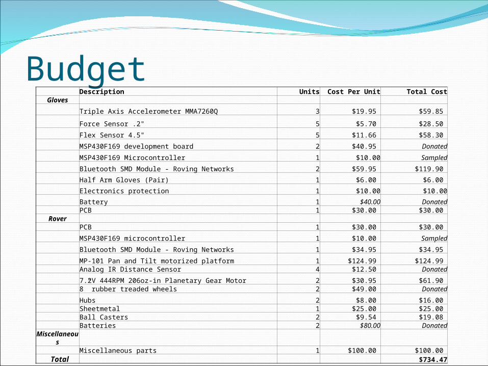
Budget Description Units Cost Per Unit Total Cost
Gloves
Triple Axis Accelerometer MMA7260Q 3 $19.95 $59.85
Force Sensor .2" 5 $5.70 $28.50
Flex Sensor 4.5" 5 $11.66 $58.30
MSP430F169 development board 2 $40.95 Donated
MSP430F169 Microcontroller 1 $10.00 Sampled
Bluetooth SMD Module - Roving Networks 2 $59.95 $119.90
Half Arm Gloves (Pair) 1 $6.00 $6.00
Electronics protection 1 $10.00 $10.00
Battery 1 $40.00 Donated PCB 1 $30.00 $30.00
Rover PCB 1 $30.00 $30.00
MSP430F169 microcontroller 1 $10.00 Sampled
Bluetooth SMD Module - Roving Networks 1 $34.95 $34.95
MP-101 Pan and Tilt motorized platform 1 $124.99 $124.99 Analog IR Distance Sensor 4 $12.50 Donated
7.2V 444RPM 206oz-in Planetary Gear Motor 2 $30.95 $61.90 8” rubber treaded wheels 2 $49.00 Donated
Hubs 2 $8.00 $16.00 Sheetmetal 1 $25.00 $25.00 Ball Casters 2 $9.54 $19.08
Batteries 2 $80.00 DonatedMiscellaneous
Miscellaneous parts 1 $100.00 $100.00 Total $734.47
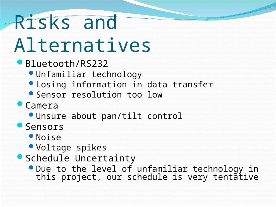
Risks and AlternativesBluetooth/RS232
Unfamiliar technologyLosing information in data transferSensor resolution too low
CameraUnsure about pan/tilt control
SensorsNoiseVoltage spikes
Schedule UncertaintyDue to the level of unfamiliar technology in this
project, our schedule is very tentative
Questions?
Camera/mounthttp://www.lightinthebox.com/Wireless-MPEG
4-Pan-Tilt-Internet-IP-Camera--Webcam-YP-06094-_p56061.html