Embed Size (px)
Citation preview
The BLEEP DRUM v001 (board 012 code 003)
Thank you for your purchase, fellow noise-maker!
Here are the tools you’ll need to assemble the Bleep Drum:
- Soldering iron Pen type, 35W max with a good tip. Like this. See Soldering 101 for more info. You will also need something to deal with soldering fumes and to clean the soldering iron. - Solder 20 gauge (.032”) is good for most kits. Large solder should be avoided. Most compo- nents we use are RoHS. Lead-free solder isn’t necessary but is recommended.- Cutters Diagonal or flush. - Small pliers Something like these.- Screwdrivers Large and mini flathead.
All Bleep Labs kits can be completed by those who are new to soldering, but it is very important that you know how to solder safely before you start. This includes working in a well-ventilated area and wearing safety glasses. Children should never solder alone and should never handle anything that might contain lead.
If you are new to soldering or need a refresher, check out these tutorials.
Resonator
CapacitorsLED 78l05
Resistors
12mm tactiles6mm tactiles
Potentiometers
1/8” jackSwitch
Atmega328 MCP4901
DIPs
9V holder
1 1/2” screw
1/4” screw
4-40 nut
Feet
Back Plate
PCB
Knobs
Page 1
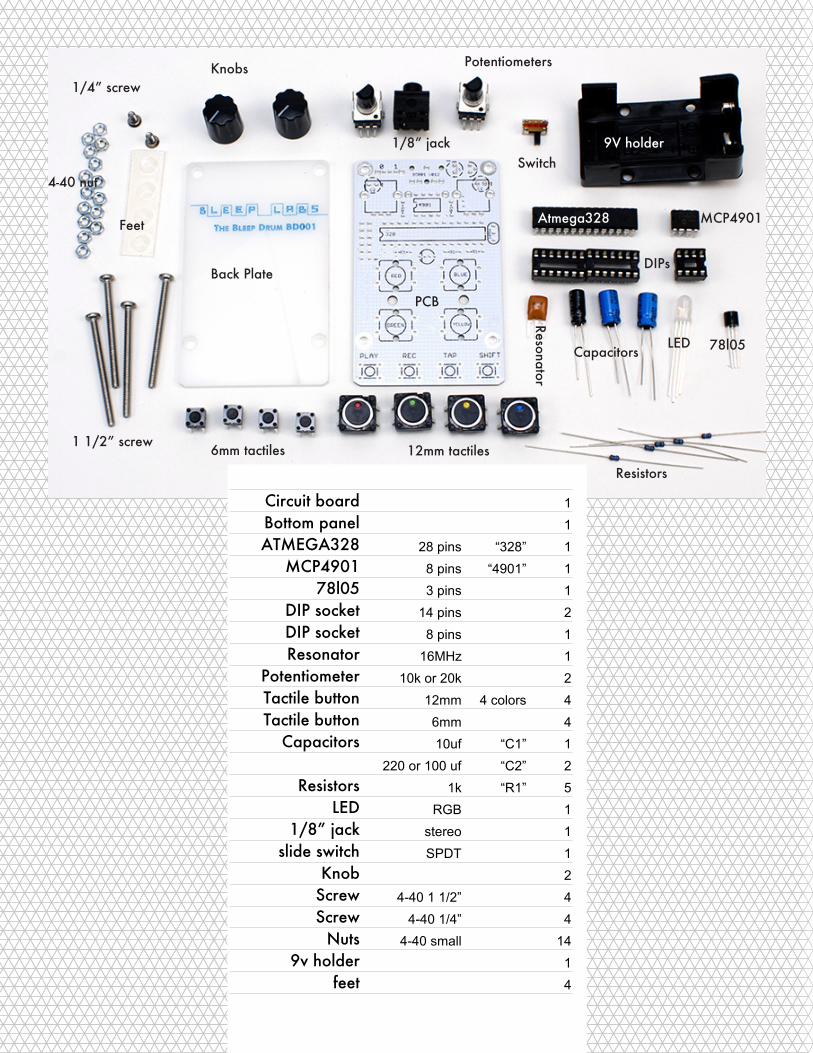
Circuit board 1
Bottom panel 1
ATMEGA328 28 pins “328” 1
MCP4901 8 pins “4901” 1
78l05 3 pins 1
DIP socket 14 pins 2
DIP socket 8 pins 1
Resonator 16MHz 1
Potentiometer 10k or 20k 2
Tactile button 12mm 4 colors 4
Tactile button 6mm 4
Capacitors 10uf “C1” 1
220 or 100 uf “C2” 2
Resistors 1k “R1” 5
LED RGB 1
1/8” jack stereo 1
slide switch SPDT 1
Knob 2
Screw 4-40 1 1/2” 4
Screw 4-40 1/4” 4
Nuts 4-40 small 14
9v holder 1
feet 4
1
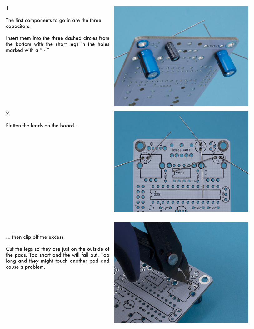
The first components to go in are the threecapacitors.
Insert them into the three dashed circles from the bottom with the short legs in the holes marked with a “ - “
2
Flatten the leads on the board...
... then clip off the excess.
Cut the legs so they are just on the outside of the pads. Too short and the will fall out. Too long and they might touch another pad and cause a problem.
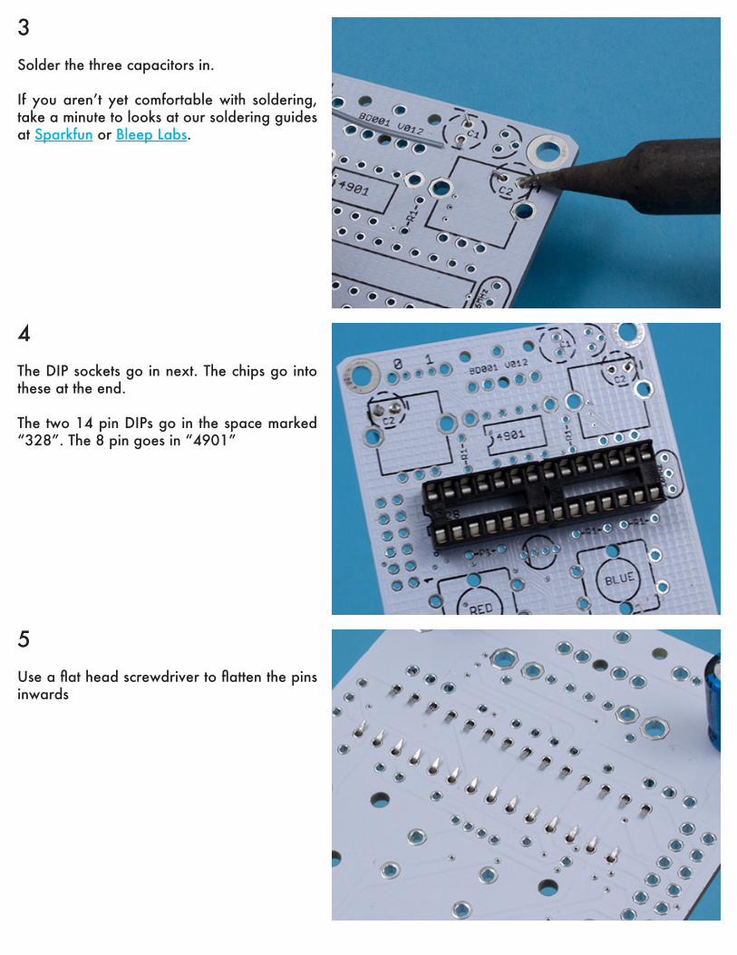
3Solder the three capacitors in.
If you aren’t yet comfortable with soldering, take a minute to looks at our soldering guides at Sparkfun or Bleep Labs.
4The DIP sockets go in next. The chips go into these at the end.
The two 14 pin DIPs go in the space marked “328”. The 8 pin goes in “4901”
5Use a flat head screwdriver to flatten the pins inwards
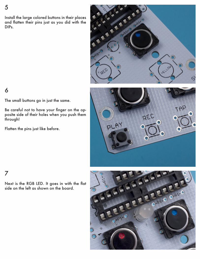
5Install the large colored buttons in their places and flatten their pins just as you did with the DIPs.
6The small buttons go in just the same.
Be careful not to have your finger on the op-posite side of their holes when you push them through!
Flatten the pins just like before.
7Next is the RGB LED. It goes in with the flat side on the left as shown on the board.

8Bend the resistors and insert them into the board in the five places marked “R1”
Bend and clip the leads as before.
9The black 78l05 and tan resonator go in as shown here.
Bend and clip their leads.
10The last components to go in on the top are the potentiometers.
Before installing them, make sure that the ca-pacitors installed on the bottom are in correct-ly as they cannot be redone after the pots are in.
You do not need to bend and clip the pots leads.
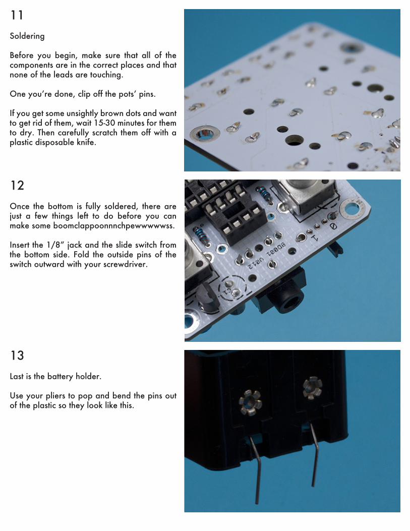
11Soldering
Before you begin, make sure that all of the components are in the correct places and that none of the leads are touching.
One you’re done, clip off the pots’ pins.
If you get some unsightly brown dots and want to get rid of them, wait 15-30 minutes for them to dry. Then carefully scratch them off with a plastic disposable knife.
12Once the bottom is fully soldered, there are just a few things left to do before you can make some boomclappoonnnchpewwwwwss.
Insert the 1/8” jack and the slide switch from the bottom side. Fold the outside pins of the switch outward with your screwdriver.
13Last is the battery holder.
Use your pliers to pop and bend the pins out of the plastic so they look like this.
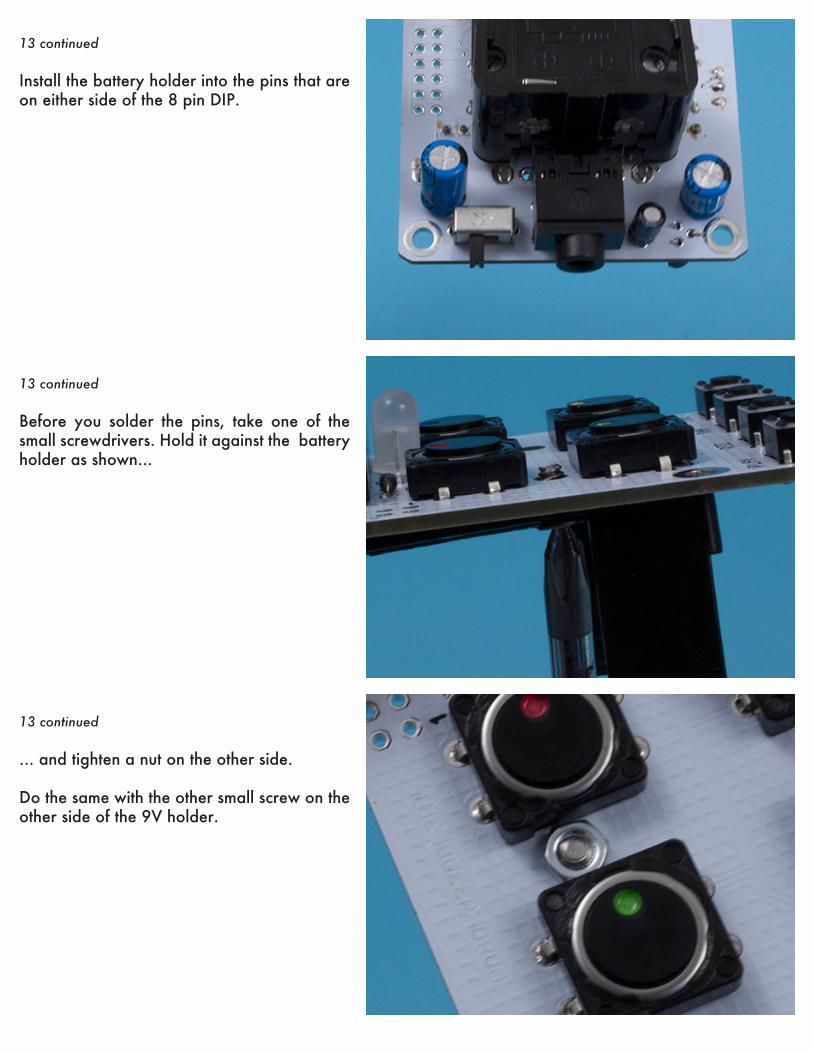
13 continued
Install the battery holder into the pins that are on either side of the 8 pin DIP.
13 continued
Before you solder the pins, take one of the small screwdrivers. Hold it against the battery holder as shown...
13 continued
... and tighten a nut on the other side.
Do the same with the other small screw on the other side of the 9V holder.
13 continued
Now solder the pins.
Make sure the battery holder is as flush to the board as you can get it. This is best achieved by holding down the board on the table while soldering the pins.
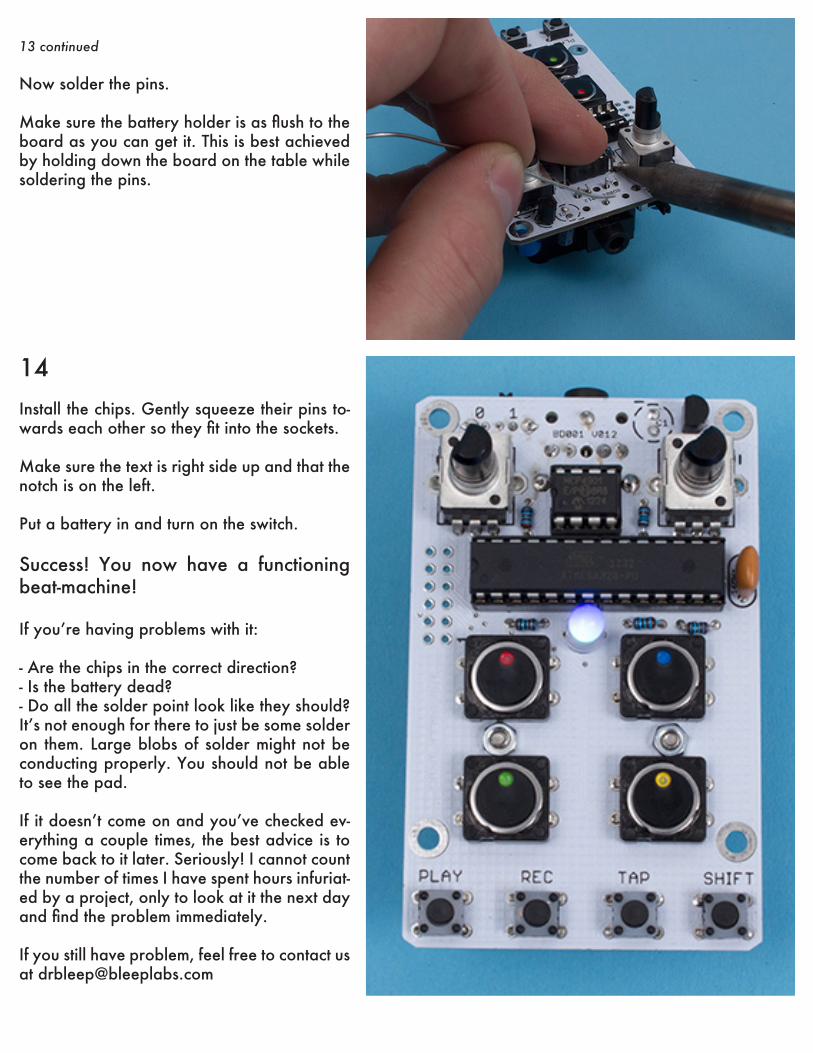
14Install the chips. Gently squeeze their pins to-wards each other so they fit into the sockets.
Make sure the text is right side up and that the notch is on the left.
Put a battery in and turn on the switch.
Success! You now have a functioning beat-machine!
If you’re having problems with it:
- Are the chips in the correct direction?- Is the battery dead?- Do all the solder point look like they should? It’s not enough for there to just be some solder on them. Large blobs of solder might not be conducting properly. You should not be able to see the pad.
If it doesn’t come on and you’ve checked ev-erything a couple times, the best advice is to come back to it later. Seriously! I cannot count the number of times I have spent hours infuriat-ed by a project, only to look at it the next day and find the problem immediately.
If you still have problem, feel free to contact us at [email protected]
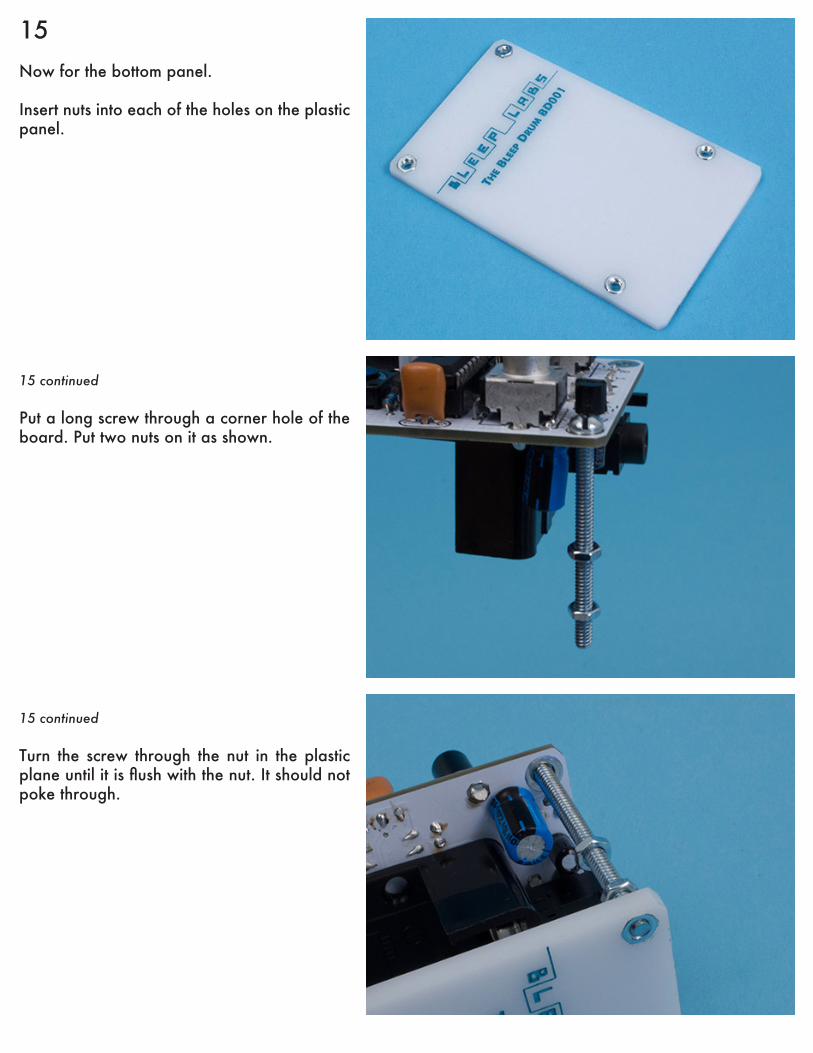
15Now for the bottom panel.
Insert nuts into each of the holes on the plastic panel.
15 continued
Put a long screw through a corner hole of the board. Put two nuts on it as shown.
15 continued
Turn the screw through the nut in the plastic plane until it is flush with the nut. It should not poke through.
15 continued
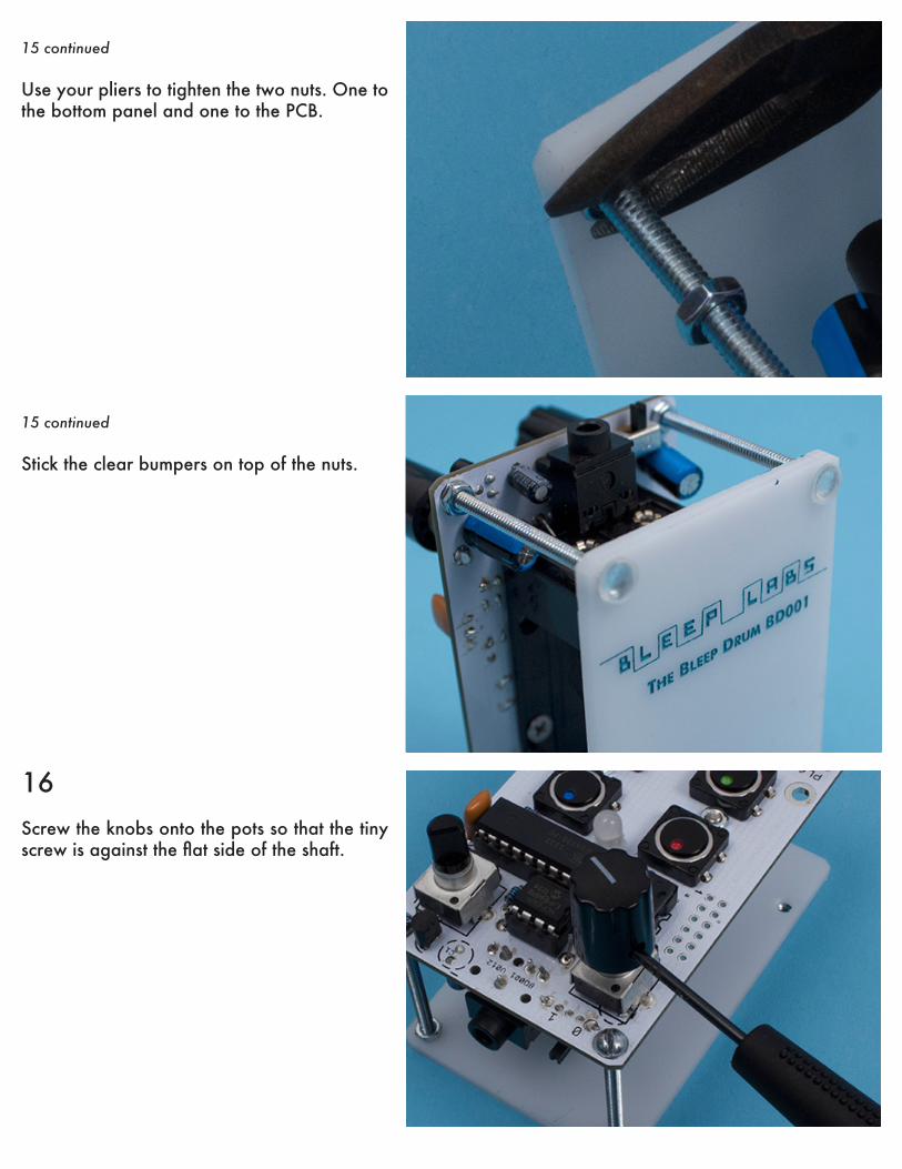
Use your pliers to tighten the two nuts. One to the bottom panel and one to the PCB.
15 continued
Stick the clear bumpers on top of the nuts.
16Screw the knobs onto the pots so that the tiny screw is against the flat side of the shaft.
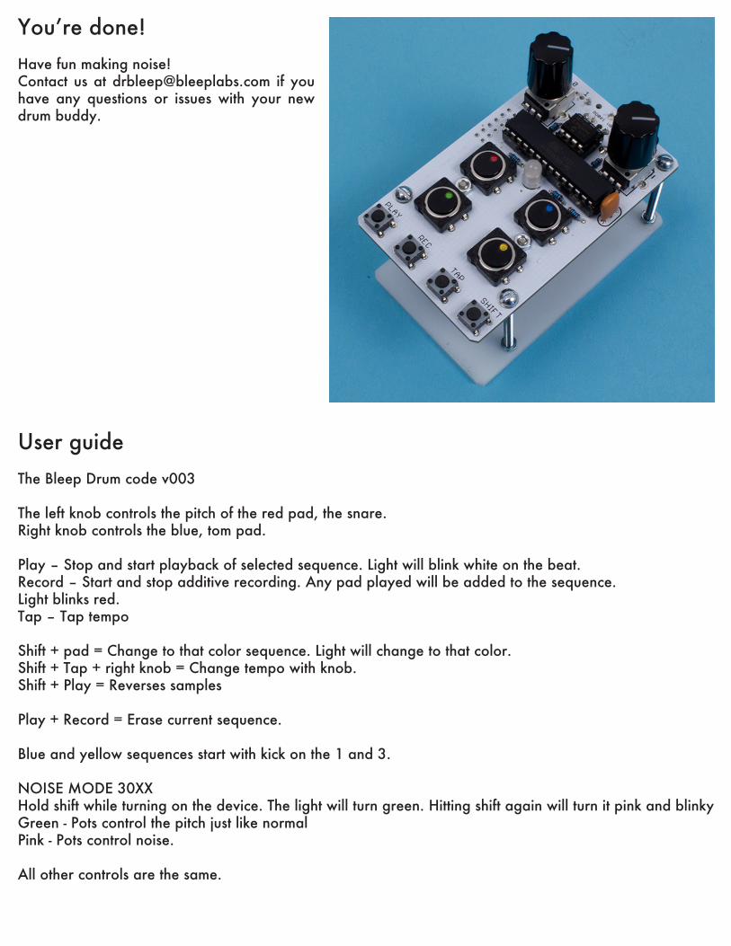
You’re done! Have fun making noise! Contact us at [email protected] if you have any questions or issues with your new drum buddy.
User guideThe Bleep Drum code v003
The left knob controls the pitch of the red pad, the snare.Right knob controls the blue, tom pad.
Play – Stop and start playback of selected sequence. Light will blink white on the beat.Record – Start and stop additive recording. Any pad played will be added to the sequence.Light blinks red.Tap – Tap tempo
Shift + pad = Change to that color sequence. Light will change to that color.Shift + Tap + right knob = Change tempo with knob.Shift + Play = Reverses samples
Play + Record = Erase current sequence.
Blue and yellow sequences start with kick on the 1 and 3.
NOISE MODE 30XXHold shift while turning on the device. The light will turn green. Hitting shift again will turn it pink and blinkyGreen - Pots control the pitch just like normalPink - Pots control noise.
All other controls are the same.
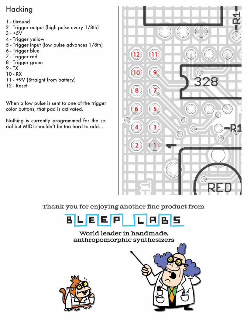
Hacking1 - Ground2 - Trigger output (high pulse every 1/8th)3 - +5V4 - Trigger yellow 5 - Trigger input (low pulse advances 1/8th)6 - Trigger blue7 - Trigger red8 - Trigger green9 - TX10 - RX11 - +9V (Straight from battery)12 - Reset
When a low pulse is sent to one of the trigger color buttons, that pad is activated.
Nothing is currently programmed for the se-rial but MIDI shouldn’t be too hard to add...