Embed Size (px)
Citation preview
Blimp User Manual for 3.9Rel © 2015 Analog Devices December 2015
Blimp
OSD development tool
By
Blimp OSD Designer
User Guide
Preliminary 0.9
No part of this document may be reproduced in any form or by any means
without the prior permission of Analog Devices Inc.
Blimp User Manual for 3.9Rel Page 2 of 70 December 2015
Copyright Information
© 2013Analog Devices, Inc., ALL RIGHTS RESERVED. This document may not be reproduced in
any form without prior, express written consent from Analog Devices, Inc.
Disclaimer
Analog Devices, Inc. (ADI) reserves the right to change this product without prior notice. Information
furnished by Analog Devices is believed to be accurate and reliable. However, no responsibility is
assumed by Analog Devices for its use; nor for any infringement of patents or other rights of third
parties which may result from its use. No license is granted by implication or otherwise under the
patent rights of Analog Devices, Inc.
The information contained in this document is proprietary of ADI. This document must not be made
available to anybody other than the intended recipient without the written permission of ADI.
The content of this document is believed to be correct. If any errors are found within this document or
if clarification is needed, contact ADI.
Trademark and Service Mark Notice
The Analog Devices logo is a registered trademark of Analog Devices, Inc. All other brand and
product names are trademarks or service marks of their respective owners.
Blimp User Manual for 3.9Rel Page 3 of 70 December 2015
Table of content
Copyright Information ...................................................................................................... 2
Disclaimer ...................................................................................................................................2
Trademark and Service Mark Notice ........................................................................................2
Preface .................................................................................................................................. 6
Product Overview ..........................................................................................................................6
Purpose of This Manual ..................................................................................................................6
Intended Audience .........................................................................................................................6
Manual Contents ............................................................................................................................6
Technical or Customer Support .......................................................................................................7
Product Information .......................................................................................................................7 Analog Devices Web Site ...................................................................................................................................... 7 EngineerZone ........................................................................................................................................................ 8 Social Networking Web Sites ................................................................................................................................ 8
Related Documents ............................................................................................................... 8
1 Main Features of OSD ..................................................................................................... 9
1.1 Description of OSD Design Flow ...........................................................................................9 1.1.1 Designing an OSD ................................................................................................................................... 10 1.1.2 Defining OSD Behaviour ......................................................................................................................... 10 1.1.3 Building an OSD ..................................................................................................................................... 11 1.1.4 Emulating and Debugging an OSD ......................................................................................................... 12 1.1.5 Integrating into MCU Project ................................................................................................................. 12
1.2 Pages Overview ................................................................................................................. 13
1.3 OSD Components Overview ............................................................................................... 13
1.4 Events Overview ............................................................................................................... 16
1.5 Focus Overview ................................................................................................................. 16
2 Installation ................................................................................................................... 17
2.1 Software Prerequisites ...................................................................................................... 17
2.2 Installing Blimp ................................................................................................................. 17
3 Getting Started ............................................................................................................. 19
3.1 Creating a New Project ...................................................................................................... 19
3.2 Opening an Existing Project ............................................................................................... 22
3.3 Features of Blimp Main Screen .......................................................................................... 22
3.4 Project Explorer Panel ....................................................................................................... 23
Blimp User Manual for 3.9Rel Page 4 of 70 December 2015
3.5 Toolbox ............................................................................................................................. 24
3.6 Property Navigator ............................................................................................................ 24
3.7 Controls ............................................................................................................................ 25
3.8 Console Window ............................................................................................................... 25
3.9 Designer Canvas ................................................................................................................ 25
3.10 Project Settings ................................................................................................................. 27
3.11 Multilanguage String Table Configuration .......................................................................... 28 3.11.1 Importing from Excel File .................................................................................................................. 29 3.11.2 Exporting to Excel File ....................................................................................................................... 29 3.11.3 Character Map Configuration ............................................................................................................ 30
3.12 Build Configuration ........................................................................................................... 33
3.13 Font Style Configuration .................................................................................................... 34
3.14 Multi Resolution Configuration .......................................................................................... 34
3.15 Image Library .................................................................................................................... 35
4 Designing an OSD ......................................................................................................... 36
4.1 Adding a Page ................................................................................................................... 36
4.2 Adding a Component ......................................................................................................... 37
4.3 Adding an Event ................................................................................................................ 37
4.4 Creating an Image and Animation ...................................................................................... 38
4.5 Creating a Textbox in ADV800x .......................................................................................... 40 4.5.1 Normal Text Entry Mode ....................................................................................................................... 41 4.5.2 Phone Text Entry Mode ......................................................................................................................... 43 4.5.3 Text Entry Using OSDKeyboard Component .......................................................................................... 43
4.6 Using a Timer in ADV800x .................................................................................................. 44
4.7 Setting Color Depth in ADV800x......................................................................................... 45
4.8 Image Format Support ....................................................................................................... 45
5 Defining OSD Behaviour in a Code Window ................................................................... 46
5.1 Introducing the Code Window ........................................................................................... 46
5.2 Blimp Scripting Language ................................................................................................... 47 5.2.1 Blimp Scripting Language Considerations .............................................................................................. 47 5.2.2 Arrays ..................................................................................................................................................... 48 5.2.3 Pointers .................................................................................................................................................. 51 5.2.4 Enumerations ......................................................................................................................................... 52 5.2.5 Structs .................................................................................................................................................... 53
5.3 Accessing Variables Between Different Pages ..................................................................... 54
Blimp User Manual for 3.9Rel Page 5 of 70 December 2015
5.4 Accessing OSD Components Properties and Methods Between Different Pages .................. 56
6 Building an OSD Project ................................................................................................ 57
6.1 Blimp Output Files ............................................................................................................. 57 6.1.1 XML Logging Files ................................................................................................................................... 58 6.1.2 Binary output file ................................................................................................................................... 58
7 Emulating and Debugging an OSD Project ..................................................................... 60
7.1 Emulator Window ............................................................................................................. 60 7.1.1 Features in Emulator Window ............................................................................................................... 61 7.1.2 Standalone Emulator ............................................................................................................................. 62
8 Integrating OSD into an MCU Project ............................................................................ 62
8.1 Porting Code for OSD Integration into MCU ....................................................................... 62
8.2 Functions to Implement .................................................................................................... 62 8.2.1 SPI Reading/Writing Functions .............................................................................................................. 62 8.2.2 Timer Interrupt Service Routine ............................................................................................................ 63
8.3 Initialization ...................................................................................................................... 63 8.3.1 Linking SPI and I2C Access Functions ..................................................................................................... 63 8.3.2 Initialize OSD .......................................................................................................................................... 64
8.4 Run Time .......................................................................................................................... 64 8.4.1 Process Interrupts .................................................................................................................................. 64 8.4.2 Send Key Presses Events ........................................................................................................................ 64
8.5 External APIs ..................................................................................................................... 65
8.6 Programming Flash............................................................................................................ 66
9 OSD Design Best Practices and examples....................................................................... 67
9.1 Sample system architecture for OSD integration ................................................................ 67
9.2 Sample projects ................................................................................................................ 67
10 Blimp ADV800x and ADV7625 Difference ................................................................... 68
11 Blimp ADV7625 and ADV7625 Static OSD Difference .................................................. 69
Appendix A: Blimp Libraries and Licenses ............................................................................. 70
Blimp User Manual for 3.9Rel Page 6 of 70 December 2015
Preface
Product Overview
The Blimp tool is used to:
Define through its graphical interface and component properties the appearance of OSD menus,
submenus, and items
Define how the navigation within the OSD works in response to user input
Call the appropriate system level function based on user interaction with the OSD
Compile and generate the ANSI-C files needed for OSD system level integration
The product features:
Easy to use GUI to design On Screen Display (OSD) menus for the ADV series with OSD
Wide range of OSD graphic components available to create state of the art OSD
Multi language configuration and Unicode character map selection
Simple integration of output generated code and ready to use compressed flash file
Purpose of This Manual
The Blimp User Manual provides information for the Blimp tool. It describes the main functions and
capabilities of the tool. It provides a detailed description of how the user can design, simulate, and
compile an OSD which can be overlaid on the video output.
Intended Audience
The primary audience for this manual is OSD designers using Blimp for ADI ADV products.
Manual Contents
The manual consists of:
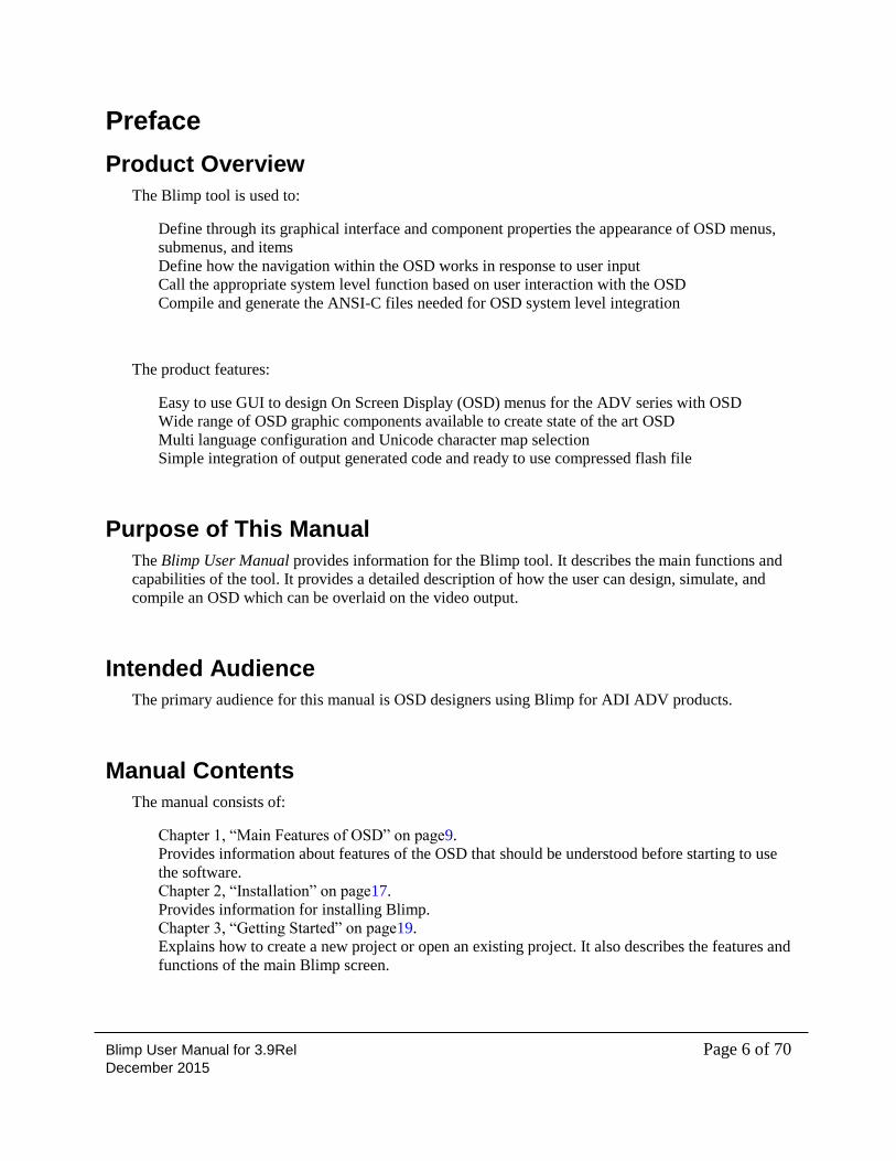
Chapter 1, “Main Features of OSD” on page9.
Provides information about features of the OSD that should be understood before starting to use
the software.
Chapter 2, “Installation” on page17.
Provides information for installing Blimp.
Chapter 3, “Getting Started” on page19.
Explains how to create a new project or open an existing project. It also describes the features and
functions of the main Blimp screen.
Blimp User Manual for 3.9Rel Page 7 of 70 December 2015
Chapter 4, “Designing an OSD” on page36.
Explains how to add and configure some of the components, events and options that define an
OSD design.
Chapter 5, “Defining OSD Behaviour in a Code Window” on page 46.
Describes how to use the code window to define the behaviour of the OSD
Chapter 6, “Building an OSD Project” on page 57.
Provides the information required in order to build an OSD project
Chapter 7, “Emulating and Debugging an OSD Project” on page 60.
Provides the information required to emulate and debug an OSD project.
Chapter 8, “Integrating an OSD into an MCU Project” on page 62.
Provides the information required to integrate the OSD into an MCU project.
Chapter 9, “Example of OSD Design and Coding” on page 67.
Provides a tutorial example for designing and coding a basic OSD.
Appendix A: “Blimp Libraries and Licenses” on page 70.
Describes the libraries used by the Blimp tool.
Technical or Customer Support
You can reach Analog Devices, Inc. Customer Support in the following ways:
Visit the Analog Devices’ Analog DVI and HDMI interfaces product web site at
http://www.analog.com/en/audiovideo-products/analoghdmidvi-interfaces/products/index.html
Post your questions in EngineerZone support: http://ez.analog.com/community/video
E-mail tools questions to
Phone questions to 1-800-ANALOGD
Contact your Analog Devices, Inc. local sales office or authorized distributor
Send questions by mail to:
Analog Devices, Inc.
One Technology Way
P.O. Box 9106
Norwood, MA 02062-9106
USA
Product Information
Product information can be obtained from the Analog Devices Web site and other Web sources.
Analog Devices Web Site
The Analog Devices Web site, www.analog.com, provides information about a broad range of
products—analog integrated circuits, amplifiers, converters, and digital signal processors.
To access a complete technical library for each processor family, go to
http://www.analog.com/processors/technical_library. The manuals selection opens a list of current
manuals related to the product as well as a link to the previous revisions of the manuals. When
Blimp User Manual for 3.9Rel Page 8 of 70 December 2015
locating your manual title, note a possible errata check mark next to the title that leads to the current
correction report against the manual.
Also note, MyAnalog.com is a free feature of the Analog Devices Web site that allows customization
of a Web page to display only the latest information about products you are interested in. You can
choose to receive weekly e-mail notifications containing updates to the Web pages that meet your
interests, including documentation errata against all manuals. MyAnalog.com provides access to
books, application notes, data sheets, code examples, and more.
Visit MyAnalog.com to sign up. If you are a registered user, just log on. Your user name is your e-
mail address.
EngineerZone
EngineerZone is a technical support forum from Analog Devices. It allows you direct access to ADI
technical support engineers. You can search FAQs and technical information to get quick answers to
your embedded processing and DSP design questions.
Social Networking Web Sites
You can now follow Analog Devices processor development on Twitter and LinkedIn. To access:
Twitter: http://twitter.com/ADIsharc and http://twitter.com/blackfin
LinkedIn: Network with the LinkedIn group: http://www.linkedin.com
Related Documents Title Version and Date
ADV7625 Blimp Framework User Manual Pr1.0November 2015
ADV800x Blimp Framework Manual Pr0.15November 2015
Blimp User Manual for 3.9Rel Page 9 of 70 December 2015
1 Main Features of OSD This chapter provides information about features of the OSD that should be understood before
starting to use the software.
The following topics are covered:
“Description of OSD Design Flow” on page 9
“Description of Components” on page 13
1.1 Description of OSD Design Flow
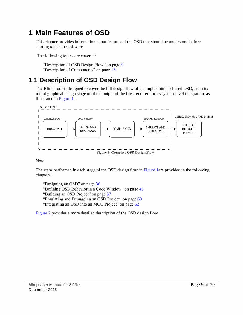
The Blimp tool is designed to cover the full design flow of a complex bitmap-based OSD, from its
initial graphical design stage until the output of the files required for its system-level integration, as
illustrated in Figure 1.
Figure 1: Complete OSD Design Flow
Note:
The steps performed in each stage of the OSD design flow in Figure 1are provided in the following
chapters:
“Designing an OSD” on page 36
“Defining OSD Behavior in a Code Window” on page 46
“Building an OSD Project” on page 57
“Emulating and Debugging an OSD Project” on page 60
“Integrating an OSD into an MCU Project” on page 62
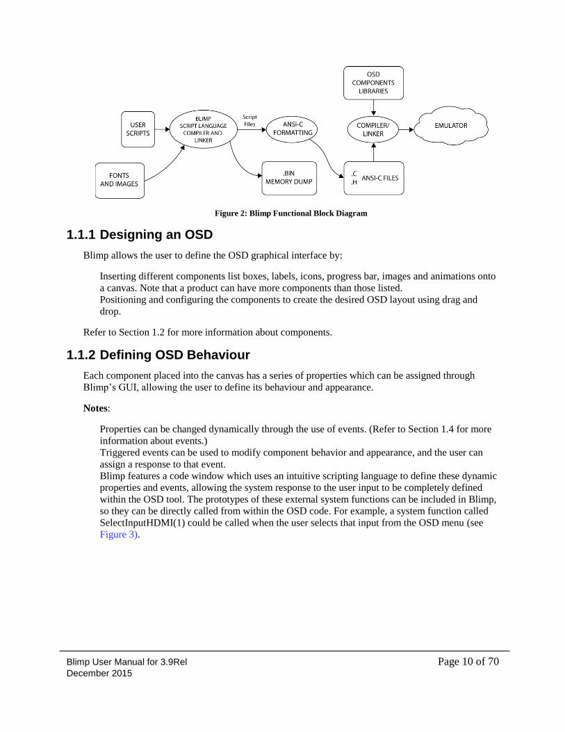
Figure 2 provides a more detailed description of the OSD design flow.
Blimp User Manual for 3.9Rel Page 10 of 70 December 2015
Figure 2: Blimp Functional Block Diagram
1.1.1 Designing an OSD
Blimp allows the user to define the OSD graphical interface by:
Inserting different components list boxes, labels, icons, progress bar, images and animations onto
a canvas. Note that a product can have more components than those listed.
Positioning and configuring the components to create the desired OSD layout using drag and
drop.
Refer to Section 1.2 for more information about components.
1.1.2 Defining OSD Behaviour
Each component placed into the canvas has a series of properties which can be assigned through
Blimp’s GUI, allowing the user to define its behaviour and appearance.
Notes:
Properties can be changed dynamically through the use of events. (Refer to Section 1.4 for more
information about events.)
Triggered events can be used to modify component behavior and appearance, and the user can
assign a response to that event.
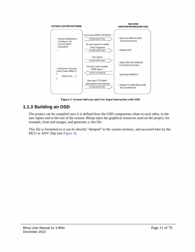
Blimp features a code window which uses an intuitive scripting language to define these dynamic
properties and events, allowing the system response to the user input to be completely defined
within the OSD tool. The prototypes of these external system functions can be included in Blimp,
so they can be directly called from within the OSD code. For example, a system function called
SelectInputHDMI(1) could be called when the user selects that input from the OSD menu (see
Figure 3).
Blimp User Manual for 3.9Rel Page 11 of 70 December 2015
Figure 3: System Software and User Input Interaction with OSD
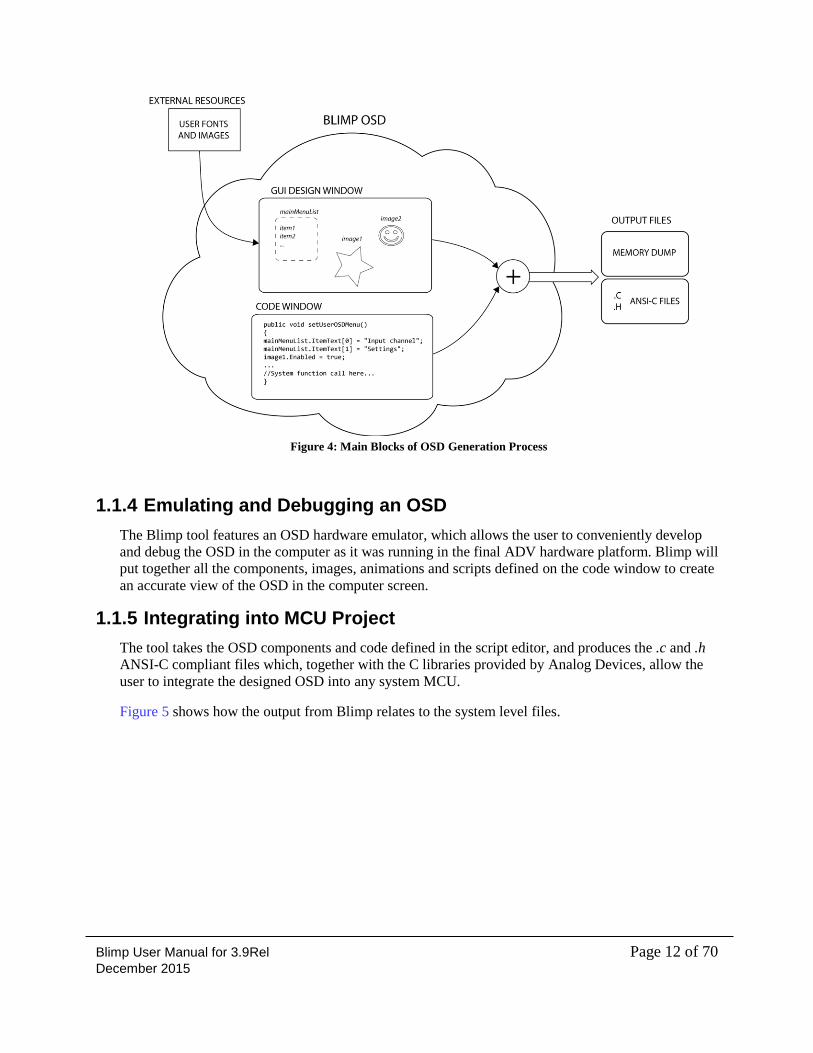
1.1.3 Building an OSD
The project can be compiled once it is defined how the OSD components relate to each other, to the
user inputs and to the rest of the system. Blimp takes the graphical resources used on the project, for
example, fonts and images, and generates a .bin file.
This file is formatted so it can be directly “dumped” to the system memory, and accessed later by the
MCU or ADV chip (see Figure 4).
Blimp User Manual for 3.9Rel Page 12 of 70 December 2015
Figure 4: Main Blocks of OSD Generation Process
1.1.4 Emulating and Debugging an OSD
The Blimp tool features an OSD hardware emulator, which allows the user to conveniently develop
and debug the OSD in the computer as it was running in the final ADV hardware platform. Blimp will
put together all the components, images, animations and scripts defined on the code window to create
an accurate view of the OSD in the computer screen.
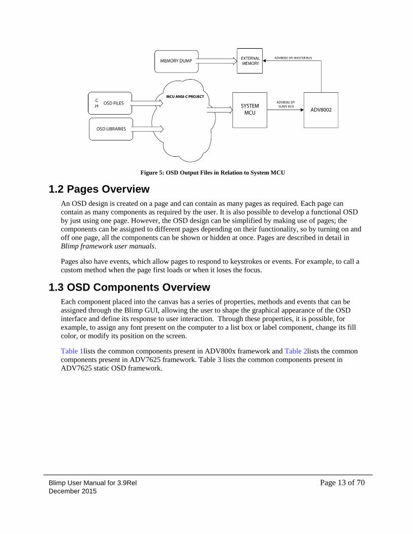
1.1.5 Integrating into MCU Project
The tool takes the OSD components and code defined in the script editor, and produces the .c and .h
ANSI-C compliant files which, together with the C libraries provided by Analog Devices, allow the
user to integrate the designed OSD into any system MCU.
Figure 5 shows how the output from Blimp relates to the system level files.
Blimp User Manual for 3.9Rel Page 13 of 70 December 2015
Figure 5: OSD Output Files in Relation to System MCU
1.2 Pages Overview
An OSD design is created on a page and can contain as many pages as required. Each page can
contain as many components as required by the user. It is also possible to develop a functional OSD
by just using one page. However, the OSD design can be simplified by making use of pages; the
components can be assigned to different pages depending on their functionality, so by turning on and
off one page, all the components can be shown or hidden at once. Pages are described in detail in
Blimp framework user manuals.
Pages also have events, which allow pages to respond to keystrokes or events. For example, to call a
custom method when the page first loads or when it loses the focus.
1.3 OSD Components Overview
Each component placed into the canvas has a series of properties, methods and events that can be
assigned through the Blimp GUI, allowing the user to shape the graphical appearance of the OSD
interface and define its response to user interaction. Through these properties, it is possible, for
example, to assign any font present on the computer to a list box or label component, change its fill
color, or modify its position on the screen.
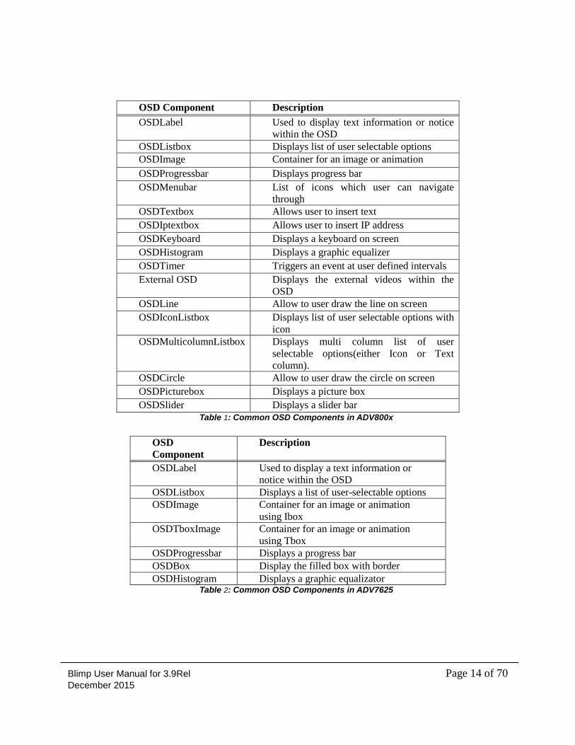
Table 1lists the common components present in ADV800x framework and Table 2lists the common
components present in ADV7625 framework. Table 3 lists the common components present in
ADV7625 static OSD framework.
Blimp User Manual for 3.9Rel Page 14 of 70 December 2015
OSD Component Description
OSDLabel Used to display text information or notice
within the OSD
OSDListbox Displays list of user selectable options
OSDImage Container for an image or animation
OSDProgressbar Displays progress bar
OSDMenubar List of icons which user can navigate
through
OSDTextbox Allows user to insert text
OSDIptextbox Allows user to insert IP address
OSDKeyboard Displays a keyboard on screen
OSDHistogram Displays a graphic equalizer
OSDTimer Triggers an event at user defined intervals
External OSD Displays the external videos within the
OSD
OSDLine Allow to user draw the line on screen
OSDIconListbox Displays list of user selectable options with
icon
OSDMulticolumnListbox Displays multi column list of user
selectable options(either Icon or Text
column).
OSDCircle Allow to user draw the circle on screen
OSDPicturebox Displays a picture box
OSDSlider Displays a slider bar
Table 1: Common OSD Components in ADV800x
OSD
Component
Description
OSDLabel Used to display a text information or
notice within the OSD
OSDListbox Displays a list of user-selectable options
OSDImage Container for an image or animation
using Ibox
OSDTboxImage Container for an image or animation
using Tbox
OSDProgressbar Displays a progress bar
OSDBox Display the filled box with border
OSDHistogram Displays a graphic equalizator Table 2: Common OSD Components in ADV7625
Blimp User Manual for 3.9Rel Page 15 of 70 December 2015
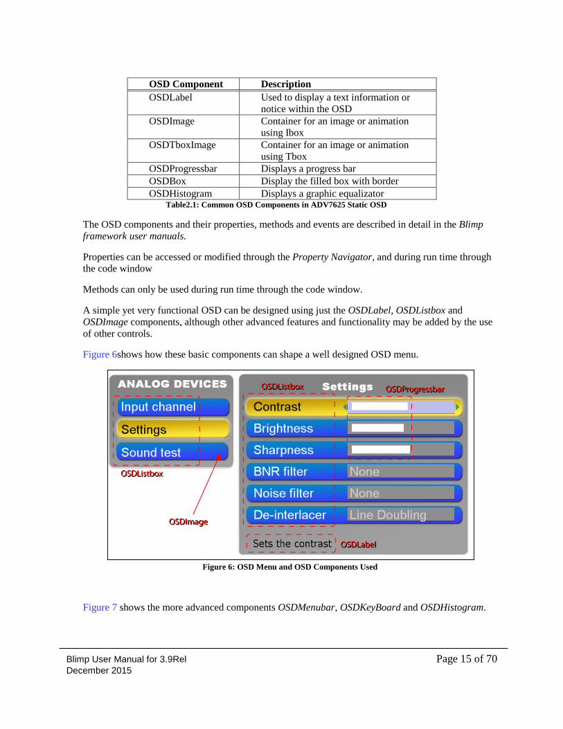
OSD Component Description
OSDLabel Used to display a text information or
notice within the OSD
OSDImage Container for an image or animation
using Ibox
OSDTboxImage Container for an image or animation
using Tbox
OSDProgressbar Displays a progress bar
OSDBox Display the filled box with border
OSDHistogram Displays a graphic equalizator Table2.1: Common OSD Components in ADV7625 Static OSD
The OSD components and their properties, methods and events are described in detail in the Blimp
framework user manuals.
Properties can be accessed or modified through the Property Navigator, and during run time through
the code window
Methods can only be used during run time through the code window.
A simple yet very functional OSD can be designed using just the OSDLabel, OSDListbox and
OSDImage components, although other advanced features and functionality may be added by the use
of other controls.
Figure 6shows how these basic components can shape a well designed OSD menu.
Figure 6: OSD Menu and OSD Components Used
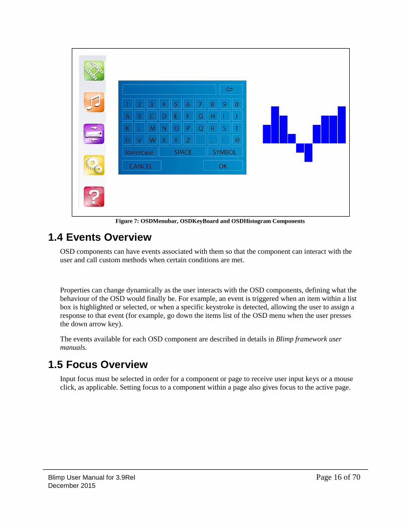
Figure 7 shows the more advanced components OSDMenubar, OSDKeyBoard and OSDHistogram.
Blimp User Manual for 3.9Rel Page 16 of 70 December 2015
Figure 7: OSDMenubar, OSDKeyBoard and OSDHistogram Components
1.4 Events Overview
OSD components can have events associated with them so that the component can interact with the
user and call custom methods when certain conditions are met.
Properties can change dynamically as the user interacts with the OSD components, defining what the
behaviour of the OSD would finally be. For example, an event is triggered when an item within a list
box is highlighted or selected, or when a specific keystroke is detected, allowing the user to assign a
response to that event (for example, go down the items list of the OSD menu when the user presses
the down arrow key).
The events available for each OSD component are described in details in Blimp framework user
manuals.
1.5 Focus Overview
Input focus must be selected in order for a component or page to receive user input keys or a mouse
click, as applicable. Setting focus to a component within a page also gives focus to the active page.
Blimp User Manual for 3.9Rel Page 17 of 70 December 2015
2 Installation This chapter provides information for installing Blimp.
The following topics are covered:
“Software Prerequisites” on page 17
“Installing Blimp” on page 17
2.1 Software Prerequisites
The Blimp software requires:
Windows XP, Windows Vista or Windows 7
Microsoft .NET Framework 4
MinGW compilers
Microsoft Excel 2007 (optional)
2.2 Installing Blimp
Follow these steps to install Blimp.
Run setup.exe.
The installation prompts to perform a .NET 4 full installations, if it is not already installed. This
requires internet access to download the package from the Microsoft site.
Next install MinGW which is required for compiling and running Blimp OSD project. This
requires internet access to download the package from the MinGW download site.
Please download an automated GUI installer assistant called mingw-get-setup.exe from the
below link. It is the preferred method for first time installation.
http://sourceforge.net/projects/mingw/?source=directory
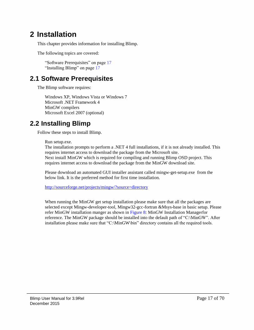
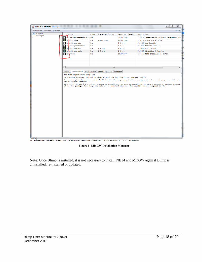
When running the MinGW get setup installation please make sure that all the packages are
selected except Mingw-developer-tool, Mingw32-gcc-fortran &Msys-base in basic setup. Please
refer MinGW installation manger as shown in Figure 8: MinGW Installation Managerfor
reference. The MinGW package should be installed into the default path of “C:\MinGW”. After
installation please make sure that “C:\MinGW\bin” directory contains all the required tools.
Blimp User Manual for 3.9Rel Page 18 of 70 December 2015
Figure 8: MinGW Installation Manager
Note: Once Blimp is installed, it is not necessary to install .NET4 and MinGW again if Blimp is
uninstalled, re-installed or updated.
Blimp User Manual for 3.9Rel Page 19 of 70 December 2015
3 Getting Started This chapter provides information for creating a new project or opening an existing project. It also
describes the features and functions of the main Blimp screen.
The following topics are covered:
“Creating a New Project” on page 19
“Opening an Existing Project” on page 22
“Features of Blimp Main Screen” on page 22
“Project Explorer Panel” on page 23
“Toolbox” on page24
“Property Navigator” on page 24
“Controls” on page25
“Console Window” on page 25
“Designer Canvas” on page 25
“Project Settings” on page 27
“Multilanguage String Table” on page 28
“Build configuration” on page 33
“Font Style configuration” on page 34
“Multi resolution configuration” on page 34
“Image Library” on page 35
3.1 Creating a New Project
Follow these steps to create a new project.
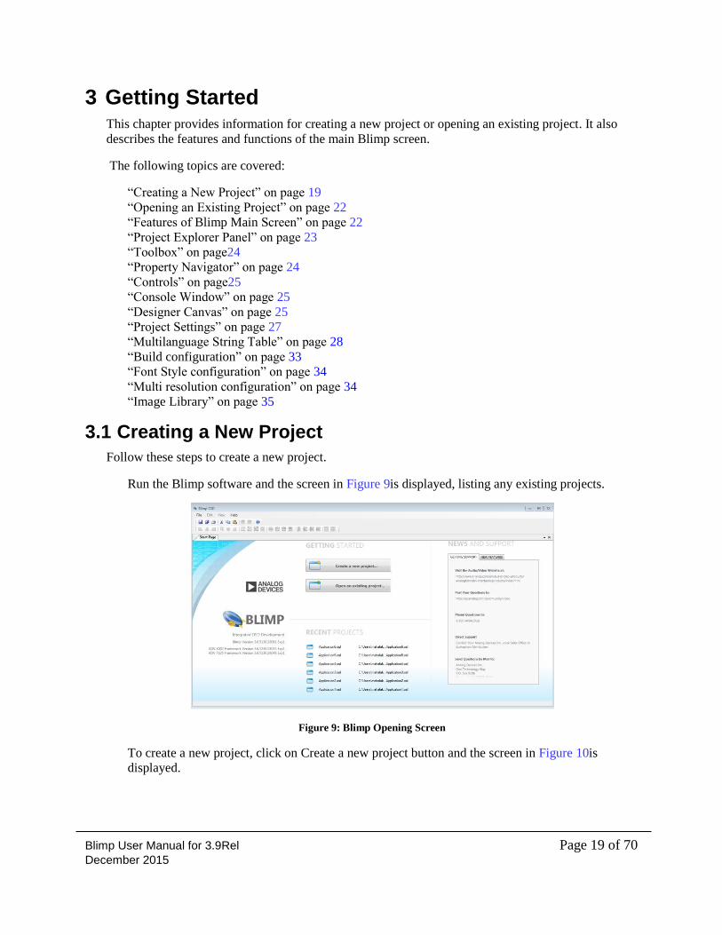
Run the Blimp software and the screen in Figure 9is displayed, listing any existing projects.
Figure 9: Blimp Opening Screen
To create a new project, click on Create a new project button and the screen in Figure 10is
displayed.
Blimp User Manual for 3.9Rel Page 20 of 70 December 2015
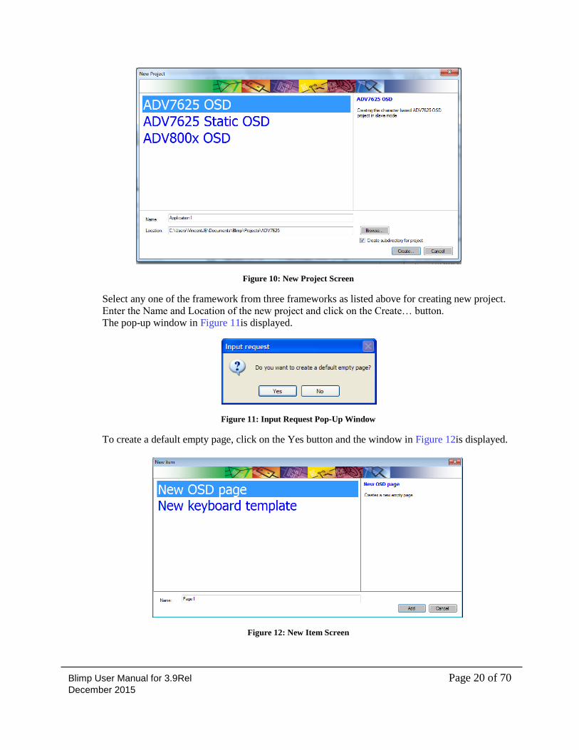
Figure 10: New Project Screen
Select any one of the framework from three frameworks as listed above for creating new project.
Enter the Name and Location of the new project and click on the Create… button.
The pop-up window in Figure 11is displayed.
Figure 11: Input Request Pop-Up Window
To create a default empty page, click on the Yes button and the window in Figure 12is displayed.
Figure 12: New Item Screen
Blimp User Manual for 3.9Rel Page 21 of 70 December 2015
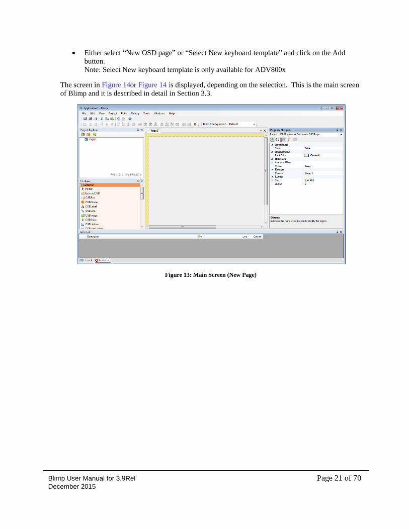
Either select “New OSD page” or “Select New keyboard template” and click on the Add
button.
Note: Select New keyboard template is only available for ADV800x
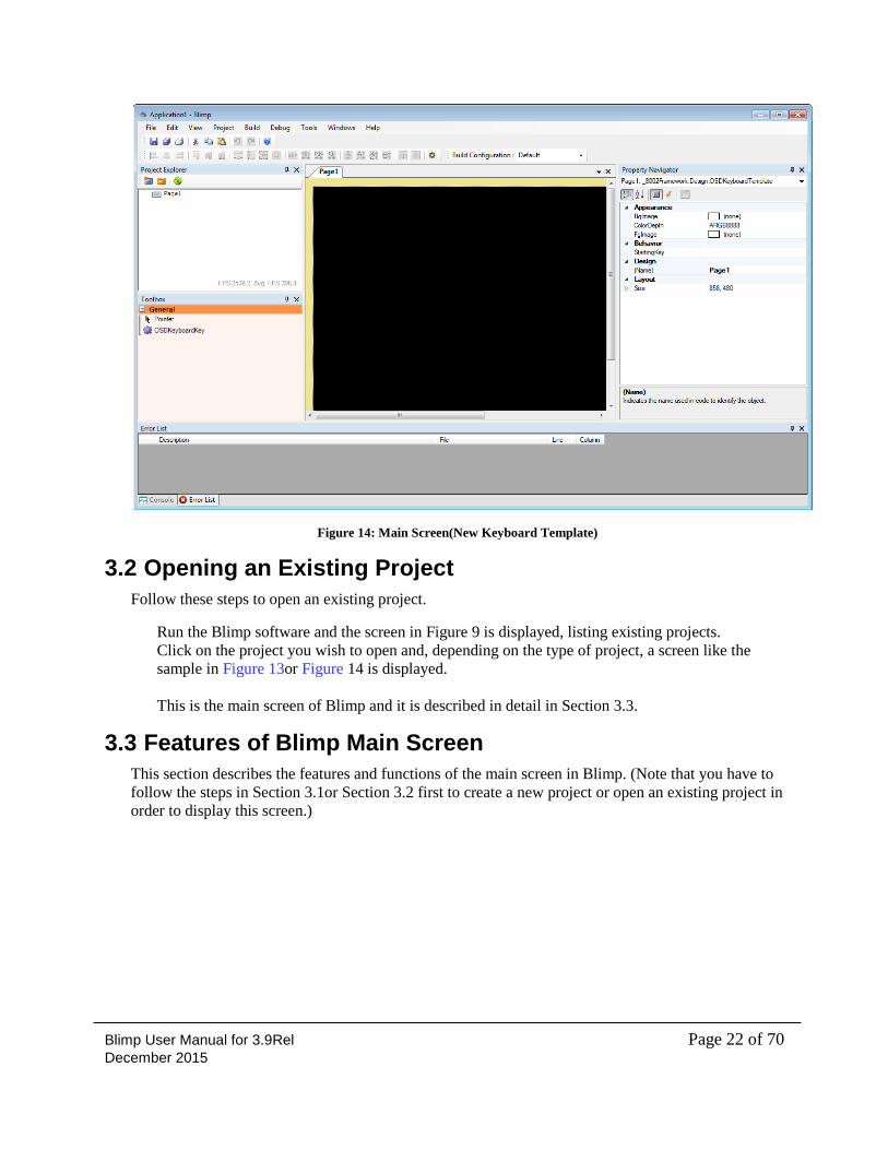
The screen in Figure 14or Figure 14 is displayed, depending on the selection. This is the main screen
of Blimp and it is described in detail in Section 3.3.
Figure 13: Main Screen (New Page)
Blimp User Manual for 3.9Rel Page 22 of 70 December 2015
Figure 14: Main Screen(New Keyboard Template)
3.2 Opening an Existing Project
Follow these steps to open an existing project.
Run the Blimp software and the screen in Figure 9 is displayed, listing existing projects.
Click on the project you wish to open and, depending on the type of project, a screen like the
sample in Figure 13or Figure 14 is displayed.
This is the main screen of Blimp and it is described in detail in Section 3.3.
3.3 Features of Blimp Main Screen
This section describes the features and functions of the main screen in Blimp. (Note that you have to
follow the steps in Section 3.1or Section 3.2 first to create a new project or open an existing project in
order to display this screen.)
Blimp User Manual for 3.9Rel Page 23 of 70 December 2015
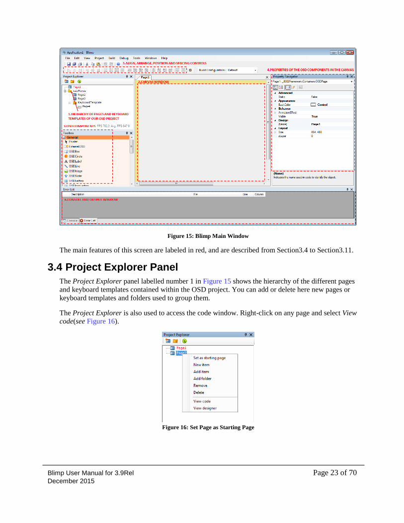
Figure 15: Blimp Main Window
The main features of this screen are labeled in red, and are described from Section3.4 to Section3.11.
3.4 Project Explorer Panel
The Project Explorer panel labelled number 1 in Figure 15 shows the hierarchy of the different pages
and keyboard templates contained within the OSD project. You can add or delete here new pages or
keyboard templates and folders used to group them.
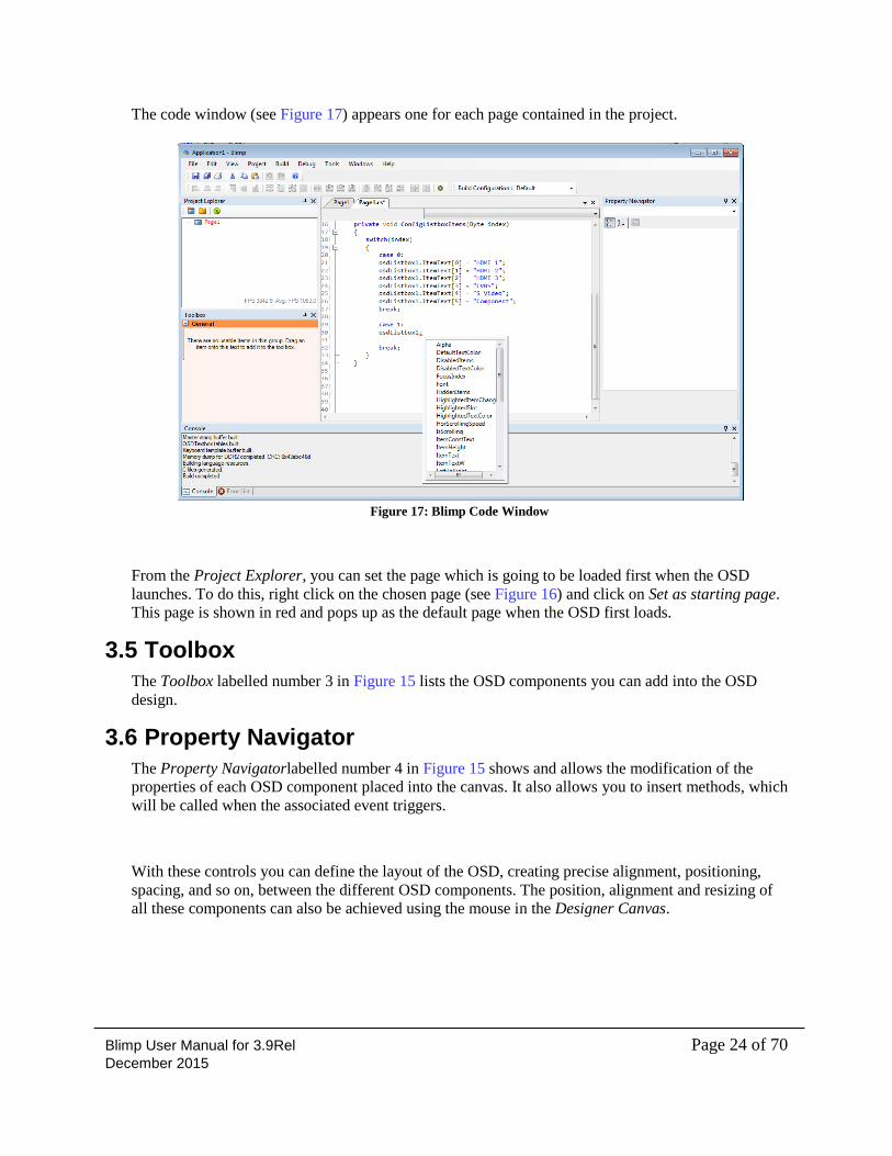
The Project Explorer is also used to access the code window. Right-click on any page and select View
code(see Figure 16).
Figure 16: Set Page as Starting Page
Blimp User Manual for 3.9Rel Page 24 of 70 December 2015
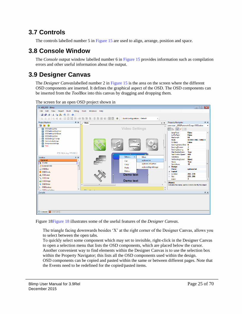
The code window (see Figure 17) appears one for each page contained in the project.
Figure 17: Blimp Code Window
From the Project Explorer, you can set the page which is going to be loaded first when the OSD
launches. To do this, right click on the chosen page (see Figure 16) and click on Set as starting page.
This page is shown in red and pops up as the default page when the OSD first loads.
3.5 Toolbox
The Toolbox labelled number 3 in Figure 15 lists the OSD components you can add into the OSD
design.
3.6 Property Navigator
The Property Navigatorlabelled number 4 in Figure 15 shows and allows the modification of the
properties of each OSD component placed into the canvas. It also allows you to insert methods, which
will be called when the associated event triggers.
With these controls you can define the layout of the OSD, creating precise alignment, positioning,
spacing, and so on, between the different OSD components. The position, alignment and resizing of
all these components can also be achieved using the mouse in the Designer Canvas.
Blimp User Manual for 3.9Rel Page 25 of 70 December 2015
3.7 Controls
The controls labelled number 5 in Figure 15 are used to align, arrange, position and space.
3.8 Console Window
The Console output window labelled number 6 in Figure 15 provides information such as compilation
errors and other useful information about the output.
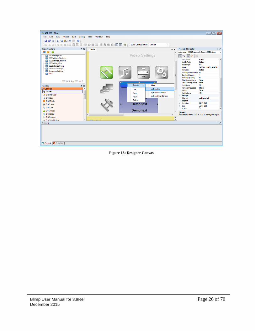
3.9 Designer Canvas
The Designer Canvaslabelled number 2 in Figure 15 is the area on the screen where the different
OSD components are inserted. It defines the graphical aspect of the OSD. The OSD components can
be inserted from the ToolBox into this canvas by dragging and dropping them.
The screen for an open OSD project shown in
Figure 18Figure 18 illustrates some of the useful features of the Designer Canvas.
The triangle facing downwards besides ‘X’ at the right corner of the Designer Canvas, allows you
to select between the open tabs.
To quickly select some component which may set to invisible, right-click in the Designer Canvas
to open a selection menu that lists the OSD components, which are placed below the cursor.
Another convenient way to find elements within the Designer Canvas is to use the selection box
within the Property Navigator; this lists all the OSD components used within the design.
OSD components can be copied and pasted within the same or between different pages. Note that
the Events need to be redefined for the copied/pasted items.
Blimp User Manual for 3.9Rel Page 26 of 70 December 2015
Figure 18: Designer Canvas
Blimp User Manual for 3.9Rel Page 27 of 70 December 2015
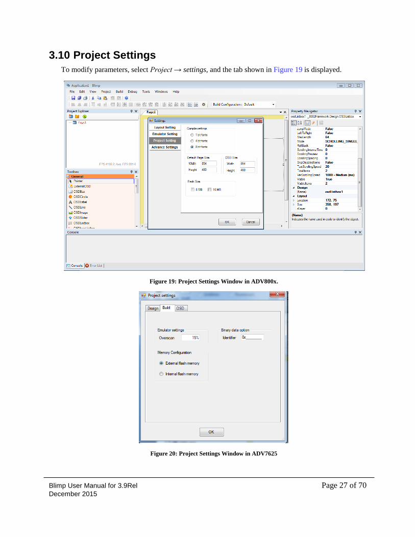
3.10 Project Settings
To modify parameters, select Project → settings, and the tab shown in Figure 19 is displayed.
Figure 19: Project Settings Window in ADV800x.
Figure 20: Project Settings Window in ADV7625
Blimp User Manual for 3.9Rel Page 28 of 70 December 2015
NOTE: Since ADV7625 Static OSD is a master mode configuration, External flash memory only
configured for ADV7625 Static OSD
The project setting is used to set build configuration and OSD parameters for the project. The project
setting is explained in details in the framework document.
3.11 Multilanguage String Table Configuration
The Blimp frameworks have support for multi language strings which can be pre-defined and switch
when the language selection is changed.
The added languages will be included within an enumeration type called OSD_LANGUAGES which
can be used to set the active language. For example, to set Spanish as the language being used in the
OSD, the next instruction should be used:
OsdApi.ADIAPI_OSDEgSetLanguage(OSD_LANGUAGES.SPANISH);
In order to be able to work with multilanguage strings, OSDLabel and OSDListbox need to use a
special property to assign the different strings previously defined; these properties are ConstText and
ItemConstText and they can only be used from the script window. The multilanguage constant string
is then assigned through the StringManager. For example:
osdListBox1.ItemConstText[0] = StringManager.IMAGE_ADJUSTMENT;
infoLabel.ConstText = StringManager.MENU_ITEM_DESCRIPTION;
It is important to note that the tool supports the use of any Unicode character when defining the
multilanguage constant strings, but the user needs to make sure that the font used in the OSDLabel or
OSDListBox also supports them; otherwise it will not be properly displayed on the emulation window
nor will it be compiled correctly.
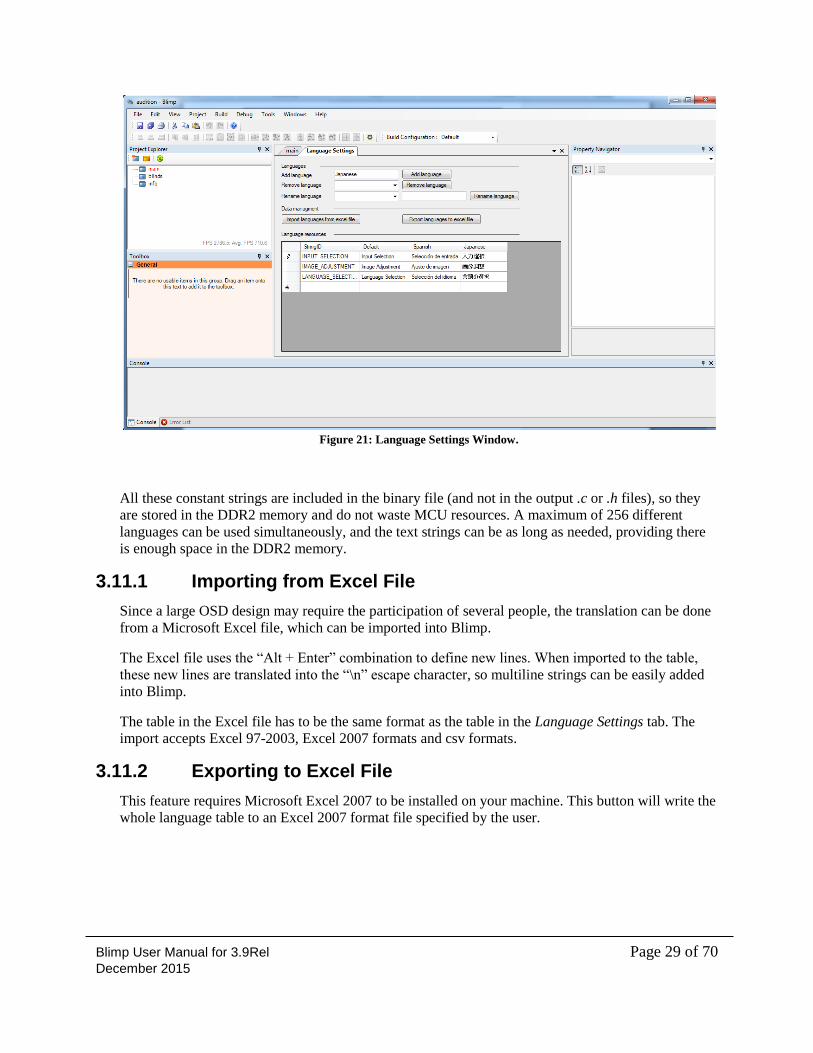
Project→ Language Settings to access the table used for defining the languages that are supported in
the OSD (see Figure 21).
Blimp User Manual for 3.9Rel Page 29 of 70 December 2015
Figure 21: Language Settings Window.
All these constant strings are included in the binary file (and not in the output .c or .h files), so they
are stored in the DDR2 memory and do not waste MCU resources. A maximum of 256 different
languages can be used simultaneously, and the text strings can be as long as needed, providing there
is enough space in the DDR2 memory.
3.11.1 Importing from Excel File
Since a large OSD design may require the participation of several people, the translation can be done
from a Microsoft Excel file, which can be imported into Blimp.
The Excel file uses the “Alt + Enter” combination to define new lines. When imported to the table,
these new lines are translated into the “\n” escape character, so multiline strings can be easily added
into Blimp.
The table in the Excel file has to be the same format as the table in the Language Settings tab. The
import accepts Excel 97-2003, Excel 2007 formats and csv formats.
3.11.2 Exporting to Excel File
This feature requires Microsoft Excel 2007 to be installed on your machine. This button will write the
whole language table to an Excel 2007 format file specified by the user.
Blimp User Manual for 3.9Rel Page 30 of 70 December 2015
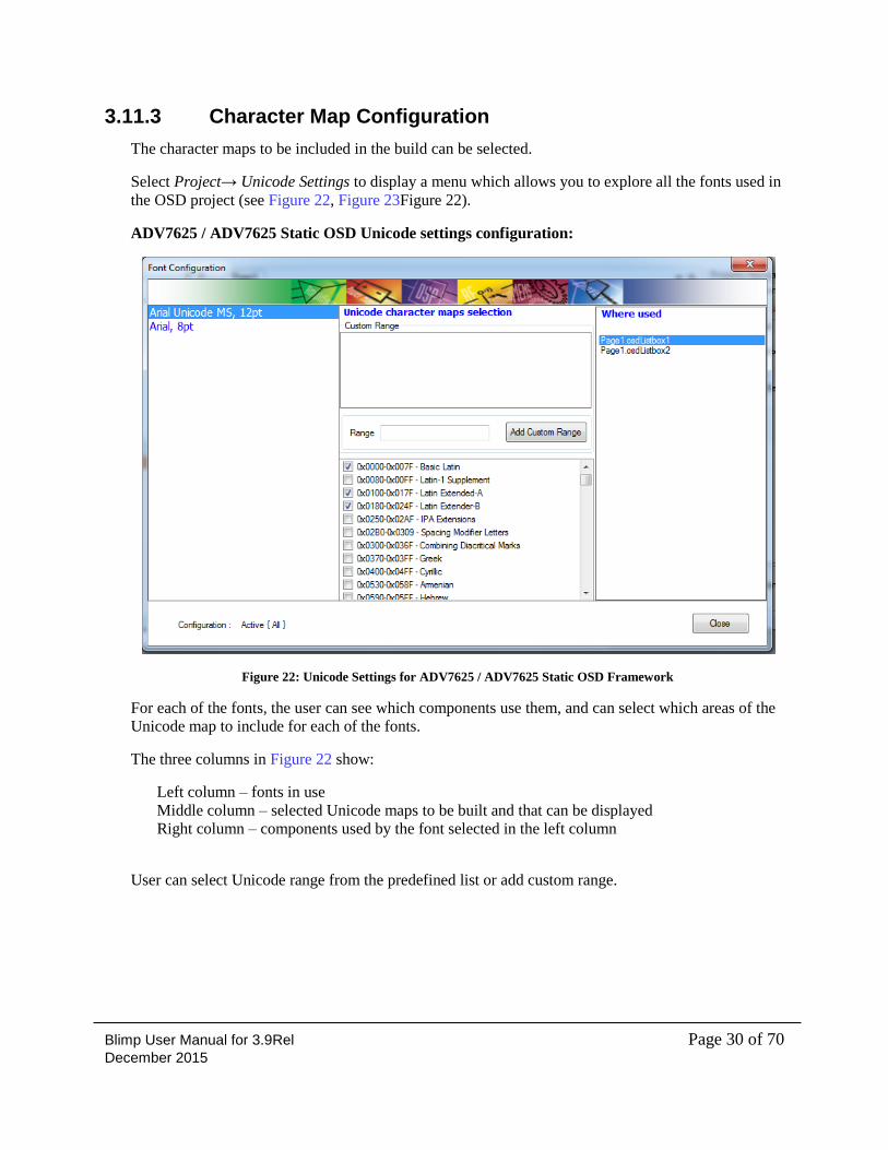
3.11.3 Character Map Configuration
The character maps to be included in the build can be selected.
Select Project→ Unicode Settings to display a menu which allows you to explore all the fonts used in
the OSD project (see Figure 22, Figure 23Figure 22).
ADV7625 / ADV7625 Static OSD Unicode settings configuration:
Figure 22: Unicode Settings for ADV7625 / ADV7625 Static OSD Framework
For each of the fonts, the user can see which components use them, and can select which areas of the
Unicode map to include for each of the fonts.
The three columns in Figure 22 show:
Left column – fonts in use
Middle column – selected Unicode maps to be built and that can be displayed
Right column – components used by the font selected in the left column
User can select Unicode range from the predefined list or add custom range.
Blimp User Manual for 3.9Rel Page 31 of 70 December 2015
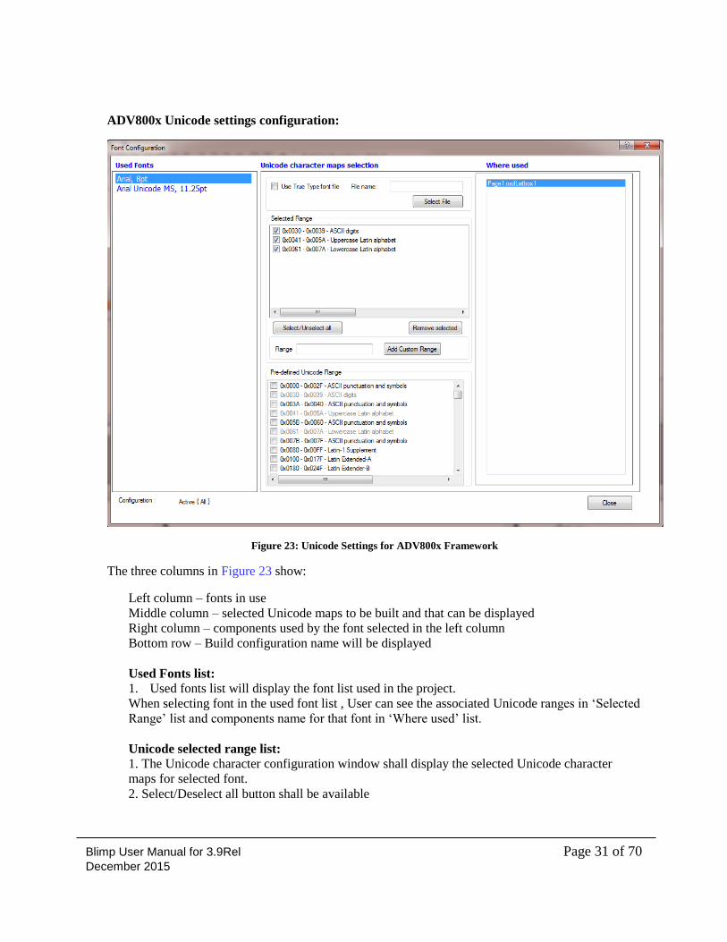
ADV800x Unicode settings configuration:
Figure 23: Unicode Settings for ADV800x Framework
The three columns in Figure 23 show:
Left column – fonts in use
Middle column – selected Unicode maps to be built and that can be displayed
Right column – components used by the font selected in the left column
Bottom row – Build configuration name will be displayed
Used Fonts list:
1. Used fonts list will display the font list used in the project.
When selecting font in the used font list , User can see the associated Unicode ranges in ‘Selected
Range’ list and components name for that font in ‘Where used’ list.
Unicode selected range list:
1. The Unicode character configuration window shall display the selected Unicode character
maps for selected font.
2. Select/Deselect all button shall be available
Blimp User Manual for 3.9Rel Page 32 of 70 December 2015
3. When right-clicking on a range, a menu will allow removing the range from the list
4. A button to remove all selected range shall be available. A confirmation dialog may be
provided
5. The name of the range can be modified and shall be saved into the project so it re-appears after
re-opening the project. The name will be lost when deleting the range.
6. When right-clicking on a range, a menu will allow renaming the range in the list
7. The range shall be shown in hexadecimal format
Unicode predefined range list:
1. For each font, the window shall allow the selection of pre-defined ranges as follow in
following order:
a. Range from a-z
b. Range from A-Z
c. Range 0-9
d. Range A-F
e. Standard Unicode maps as defined in http://www.unicode.org/charts/
2. Double clinking on the range shall add it to the selected list.
3. Right click on a range a menu Add Selected/Remove Selected will be available to Add or
remove range from the selected list depending if it is selected.
4. A selected range will be grayed out but right click will still show option to remove it from list
5. Multiple selections is possible and right clicking should allow to add the multiple selected
ranges to the selected list
Add custom range:
1 .For each font, the Unicode selection will allow the user to select a user defined range of
Unicode characters by specifying the range. The text box input and button to add the range are
provided as shown in GUI.
2. Custom range will accept either a range defined as [ {lower Unicode code} - {higher Unicode
code}] or unique entries in Unicode codes divided by a coma.
Example: The range can be defined as [0x30 - 0x39]
3. The UI shall be able to accept single characters in Unicode format to specify the range. Single
characters will be treated in this format by default.
4. The UI shall also accept hexadecimal format with format 0xnn. If a number has more than one
digit and has a-f, then it shall be assumed as hexadecimal
5. Any entry in decimal with more than one digit will be read as decimal number representation.
6. The name in the selected range window will display default name. User can use rename option
to rename the range. Note that the range displayed will be in hexadecimal.
Please note that the Unicode ranges in the selected range list only will be compiled when
building/emulating project.
Notes:
Blimp User Manual for 3.9Rel Page 33 of 70 December 2015
The font must contain the Unicode characters being used within the OSD, otherwise no characters
will be compiled and the text components will be empty.
Not all the fonts have a complete Unicode set.
Fonts must have Unicode support if Unicode character maps are required.
The more Unicode maps that are included, the bigger the resulting memory dump. For example,
including the CJK area of the Unicode map (Japanese and Chinese area) increases the size of the
uncompressed binary dump for 5.7 MB (extra 2.8 MB if compressed) for a 15-point font.
Even if this increase in size seems reasonable for the extra 28,607 characters, further size
reduction of the memory dump can be achieved by downgrading the font resolution from eight
bits to four bits. In the example of the 15-point font including the CJK area, the use of 4-bit fonts
would save around 40% of the memory compared to when using 8-bit fonts.
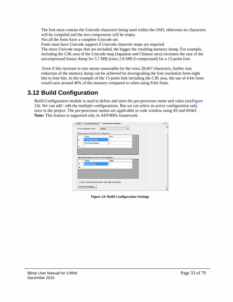
3.12 Build Configuration
Build Configuration module is used to define and store the pre-processor name and value (seeFigure
24). We can add / edit the multiple configurations. But we can select an active configuration only
once in the project. The pre-processor names are applicable in code window using #if and #ifdef.
Note: This feature is supported only in ADV800x framework.
Figure 24: Build Configuration Settings
Blimp User Manual for 3.9Rel Page 34 of 70 December 2015
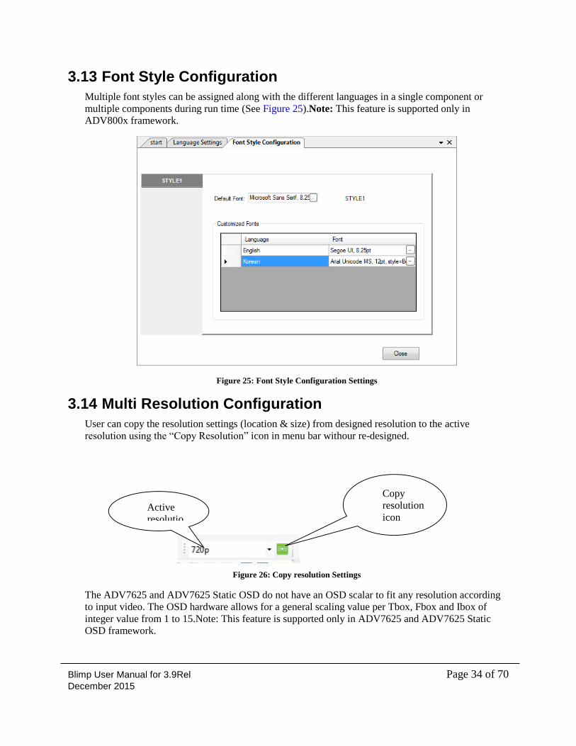
3.13 Font Style Configuration
Multiple font styles can be assigned along with the different languages in a single component or
multiple components during run time (See Figure 25).Note: This feature is supported only in
ADV800x framework.
Figure 25: Font Style Configuration Settings
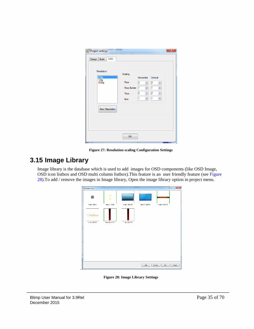
3.14 Multi Resolution Configuration
User can copy the resolution settings (location & size) from designed resolution to the active
resolution using the “Copy Resolution” icon in menu bar withour re-designed.
Figure 26: Copy resolution Settings
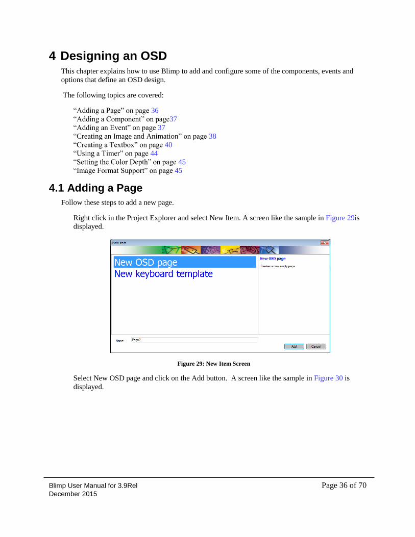
The ADV7625 and ADV7625 Static OSD do not have an OSD scalar to fit any resolution according
to input video. The OSD hardware allows for a general scaling value per Tbox, Fbox and Ibox of
integer value from 1 to 15.Note: This feature is supported only in ADV7625 and ADV7625 Static
OSD framework.
Copy
resolution
icon Active
resolutio
n
Blimp User Manual for 3.9Rel Page 35 of 70 December 2015
Figure 27: Resolution scaling Configuration Settings
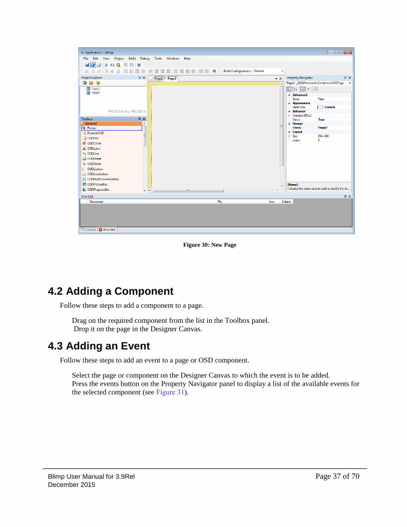
3.15 Image Library
Image library is the database which is used to add images for OSD components (like OSD Image,
OSD icon listbox and OSD multi column listbox).This feature is an user friendly feature (see Figure
28).To add / remove the images in Image library, Open the image library option in project menu.
.
Figure 28: Image Library Settings
Blimp User Manual for 3.9Rel Page 36 of 70 December 2015
4 Designing an OSD This chapter explains how to use Blimp to add and configure some of the components, events and
options that define an OSD design.
The following topics are covered:
“Adding a Page” on page 36
“Adding a Component” on page37
“Adding an Event” on page 37
“Creating an Image and Animation” on page 38
“Creating a Textbox” on page 40
“Using a Timer” on page 44
“Setting the Color Depth” on page 45
“Image Format Support” on page 45
4.1 Adding a Page
Follow these steps to add a new page.
Right click in the Project Explorer and select New Item. A screen like the sample in Figure 29is
displayed.
Figure 29: New Item Screen
Select New OSD page and click on the Add button. A screen like the sample in Figure 30 is
displayed.
Blimp User Manual for 3.9Rel Page 37 of 70 December 2015
Figure 30: New Page
4.2 Adding a Component
Follow these steps to add a component to a page.
Drag on the required component from the list in the Toolbox panel.
Drop it on the page in the Designer Canvas.
4.3 Adding an Event
Follow these steps to add an event to a page or OSD component.
Select the page or component on the Designer Canvas to which the event is to be added.
Press the events button on the Property Navigator panel to display a list of the available events for
the selected component (see Figure 31).
Blimp User Manual for 3.9Rel Page 38 of 70 December 2015
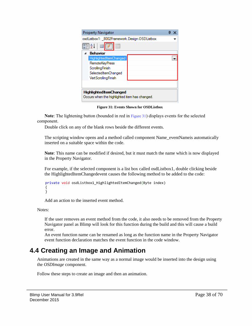
Figure 31: Events Shown for OSDListbox
Note: The lightening button (bounded in red in Figure 31) displays events for the selected
component.
Double click on any of the blank rows beside the different events.
The scripting window opens and a method called component Name_eventNameis automatically
inserted on a suitable space within the code.
Note: This name can be modified if desired, but it must match the name which is now displayed
in the Property Navigator.
For example, if the selected component is a list box called osdListbox1, double clicking beside
the HighlightedItemChangedevent causes the following method to be added to the code:
private void osdListbox1_HighlightedItemChanged(Byte index) { }
Add an action to the inserted event method.
Notes:
If the user removes an event method from the code, it also needs to be removed from the Property
Navigator panel as Blimp will look for this function during the build and this will cause a build
error.
An event function name can be renamed as long as the function name in the Property Navigator
event function declaration matches the event function in the code window.
4.4 Creating an Image and Animation
Animations are created in the same way as a normal image would be inserted into the design using
the OSDImage component.
Follow these steps to create an image and then an animation.
Blimp User Manual for 3.9Rel Page 39 of 70 December 2015
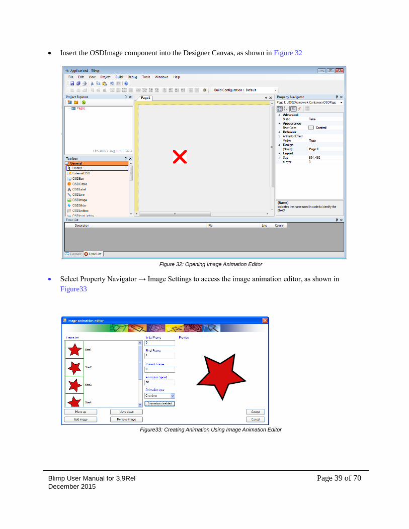
Insert the OSDImage component into the Designer Canvas, as shown in Figure 32
Figure 32: Opening Image Animation Editor
Select Property Navigator → Image Settings to access the image animation editor, as shown in
Figure33
Figure33: Creating Animation Using Image Animation Editor
Blimp User Manual for 3.9Rel Page 40 of 70 December 2015
On the screen illustrated in Figure33 insert and arrange the frames which will define the animation or
the static image if only one frame is defined.
All the selected frames must be the same size.
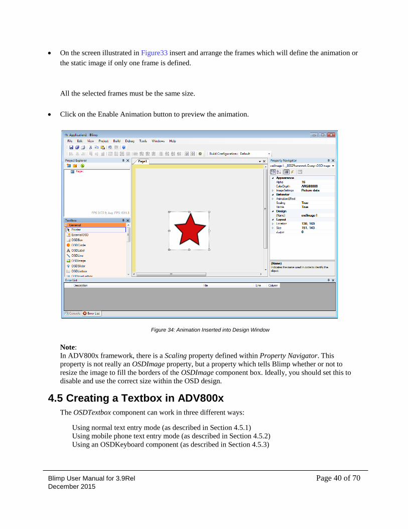
Click on the Enable Animation button to preview the animation.
Figure 34: Animation Inserted into Design Window
Note:
In ADV800x framework, there is a Scaling property defined within Property Navigator. This
property is not really an OSDImage property, but a property which tells Blimp whether or not to
resize the image to fill the borders of the OSDImage component box. Ideally, you should set this to
disable and use the correct size within the OSD design.
4.5 Creating a Textbox in ADV800x
The OSDTextbox component can work in three different ways:
Using normal text entry mode (as described in Section 4.5.1)
Using mobile phone text entry mode (as described in Section 4.5.2)
Using an OSDKeyboard component (as described in Section 4.5.3)
Blimp User Manual for 3.9Rel Page 41 of 70 December 2015
4.5.1 Normal Text Entry Mode
The OSDTextbox component works in this mode by default.
Follow these steps to create a textbox in normal mode when the focus is set on the component.
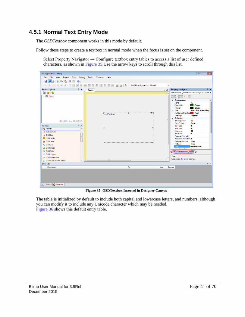
Select Property Navigator → Configure textbox entry tables to access a list of user defined
characters, as shown in Figure 35.Use the arrow keys to scroll through this list.
Figure 35: OSDTextbox Inserted in Designer Canvas
The table is initialized by default to include both capital and lowercase letters, and numbers, although
you can modify it to include any Unicode character which may be needed.
Figure 36 shows this default entry table.
Blimp User Manual for 3.9Rel Page 42 of 70 December 2015
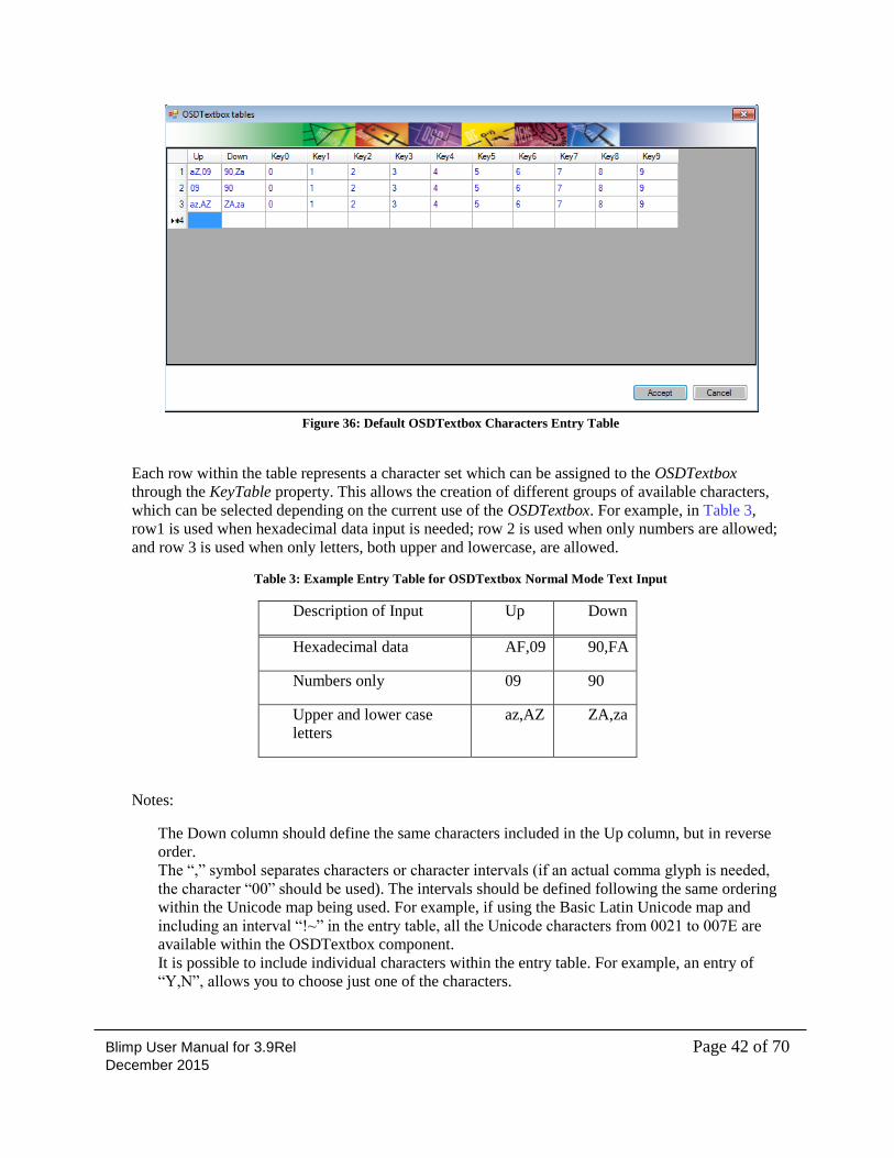
Figure 36: Default OSDTextbox Characters Entry Table
Each row within the table represents a character set which can be assigned to the OSDTextbox
through the KeyTable property. This allows the creation of different groups of available characters,
which can be selected depending on the current use of the OSDTextbox. For example, in Table 3,
row1 is used when hexadecimal data input is needed; row 2 is used when only numbers are allowed;
and row 3 is used when only letters, both upper and lowercase, are allowed.
Table 3: Example Entry Table for OSDTextbox Normal Mode Text Input
Description of Input Up Down
Hexadecimal data AF,09 90,FA
Numbers only 09 90
Upper and lower case
letters
az,AZ ZA,za
Notes:
The Down column should define the same characters included in the Up column, but in reverse
order.
The “,” symbol separates characters or character intervals (if an actual comma glyph is needed,
the character “00” should be used). The intervals should be defined following the same ordering
within the Unicode map being used. For example, if using the Basic Latin Unicode map and
including an interval “!~” in the entry table, all the Unicode characters from 0021 to 007E are
available within the OSDTextbox component.
It is possible to include individual characters within the entry table. For example, an entry of
“Y,N”, allows you to choose just one of the characters.
Blimp User Manual for 3.9Rel Page 43 of 70 December 2015
A KeyTable can be changed in run time in the code window for a specific textbox.
Move from one entry table character set to another by using the following code :
osdTextbox1.KeyTable = 1;//Use the character set defined in row 1
osdTextbox1.KeyTable = 2;//Use the character set defined in row 2
osdTextbox1.KeyTable = 3;//Use the character set defined in row 3
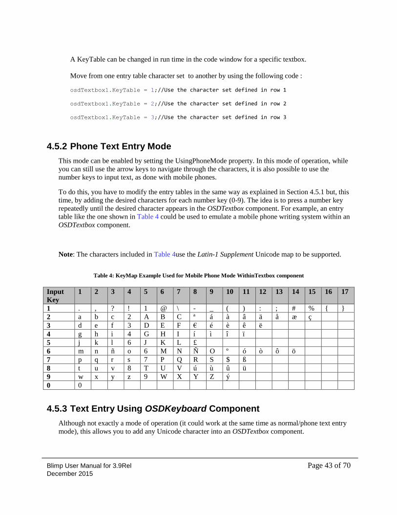
4.5.2 Phone Text Entry Mode
This mode can be enabled by setting the UsingPhoneMode property. In this mode of operation, while
you can still use the arrow keys to navigate through the characters, it is also possible to use the
number keys to input text, as done with mobile phones.
To do this, you have to modify the entry tables in the same way as explained in Section 4.5.1 but, this
time, by adding the desired characters for each number key (0-9). The idea is to press a number key
repeatedly until the desired character appears in the OSDTextbox component. For example, an entry
table like the one shown in Table 4 could be used to emulate a mobile phone writing system within an
OSDTextbox component.
Note: The characters included in Table 4use the Latin-1 Supplement Unicode map to be supported.
Table 4: KeyMap Example Used for Mobile Phone Mode WithinTextbox component
Input
Key
1 2 3 4 5 6 7 8 9 10 11 12 13 14 15 16 17
1 . , ? ! 1 @ \ - _ ( ) : ; # % { }
2 a b c 2 A B C ª á à â ä å æ ç
3 d e f 3 D E F € é è ê ë
4 g h i 4 G H I í ì î ï
5 j k l 6 J K L £
6 m n ñ o 6 M N Ñ O º ó ò ô ö
7 p q r s 7 P Q R S $ ß
8 t u v 8 T U V ú ù û ü
9 w x y z 9 W X Y Z ý
0 0
4.5.3 Text Entry Using OSDKeyboard Component
Although not exactly a mode of operation (it could work at the same time as normal/phone text entry
mode), this allows you to add any Unicode character into an OSDTextbox component.
Blimp User Manual for 3.9Rel Page 44 of 70 December 2015
In this case, the characters are appended through an OSDKeyboardcomponent. The approach here is
to give focus to the keyboard component and, from its KeySelected event, call the methods of the
OSDTextbox to move the cursor, remove or add characters, depending on the keys pressed in the
keyboard. The following example shows this.
private void osdKeyboard1_KeySelected(UInt16 keyCode)
{
if (keyCode == 64) //Delete key within the keyboard
{
osdTextbox1.delChar();
}
else if (keyCode == 45) //Left arrow key within the keyboard
{
osdTextbox1.moveCursorPrev();
}
else if (keyCode == 94) //Right arrow key within the keyboard
{
osdTextbox1.moveCursorNext();
}
else
{
osdTextbox1.appendChar(keyCode);//Any other key, append it to the textbox
}
}
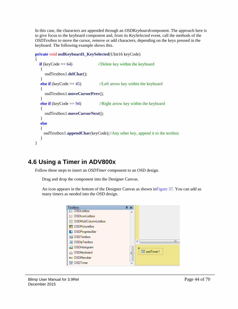
4.6 Using a Timer in ADV800x
Follow these steps to insert an OSDTimer component to an OSD design.
Drag and drop the component into the Designer Canvas.
An icon appears in the bottom of the Designer Canvas as shown inFigure 37. You can add as
many timers as needed into the OSD design.
Blimp User Manual for 3.9Rel Page 45 of 70 December 2015
Figure 37: Inserting OSDTimer Component into OSD Design
Select Property Navigator → Interval to set the time interval which the timer should count up to.
Each unit added into this field means a delay of 500ms, in other words, if a value of 10 is added,
the interval being set is actually 500ms x 10 = 5s.
The OSDTimer is ready now to be used; it just needs to be enabled. This can be done through its
Enabled property within the code window. Refer to the OSDTimer description in the Blimp
framework user manuals for an example of how to do this.
4.7 Setting Color Depth in ADV800x
Blimp supports several color depths for components with images.
This allows saving memory and having optimal color distribution in OSD graphics. The color depth
definition is specific to each framework.
The color depth can be selected within a component through the property navigator as follow:
Select Property Navigator → ColorDepth.
Set the following color depths, as appropriate:
o RGB565: 16-bit color depth (5 bits for red, 6 bits for green, and 5 bits for blue
components)
o ARGB4444: 12-bit color depth with alpha channel (4 bits for red, 4 bits for green, 4 bits
for blue components, and 4 bits for alpha channel).
o ARGB8888: 24-bit color depth with alpha channel (8 bits for red, 8 bits for green, 8 bits
for blue components, and 8 bits for alpha channel).
o PALETTE: In palette mode, each pixel color will be added and maximum of 256 pixels
colors can be added in to binary.
Note: Blimp displays the images in the same way, that is, in the native format of the picture inserted
independently of the color depth selected, although the memory dump and compiled files take it into
account.
4.8 Image Format Support
Blimp supports any Windows supported image file; the only exceptions are animated formats or
exotic pixel formats of BMP models like including alpha in a BMP. The recommended file format for
static images and animations is PNG format.
Blimp User Manual for 3.9Rel Page 46 of 70 December 2015
5 Defining OSD Behaviour in a Code Window This chapter describes how to use the code window to define the behaviour of the OSD.
The following topics are covered:
“Introducing the Code Window” on page 46
“Blimp Scripting Language” on page 47
“Pointers” on page 51
“Enumerations” on page 52
“Structs” on page 53
5.1 Introducing the Code Window
The code window allows you to define the behaviour of the OSD, how it will respond to user
interaction, and how it will interact with the system software.
To facilitate this task, a high-level scripting language is used, allowing you to focus quickly on the
development of the OSD. This removes the need to use pointers, functions declaration, and so on,
which you may experience with, for example, an ANSI-C compiler. However, since C code that can
be ported to a custom microcontroller is eventually needed, Blimp parses the scripting language used
here to an ANSI-C compliant code when generating the output files.
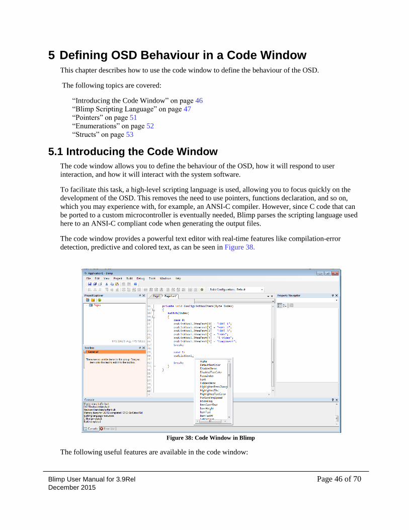
The code window provides a powerful text editor with real-time features like compilation-error
detection, predictive and colored text, as can be seen in Figure 38.
Figure 38: Code Window in Blimp
The following useful features are available in the code window:
Blimp User Manual for 3.9Rel Page 47 of 70 December 2015
Text string search can be done through the Control + F keyboard shortcut.
If there is more than one string occurrence within the code, a forward search and a backward
search can be done with F3 and Shift + F3, respectively.
The triangle facing downwards besides the ‘x’ at the right corner of the code window, allows
selecting between tabs.
Can change the curser position to the specific line number through Control + G keyboard
shortcut.
5.2 Blimp Scripting Language
The syntax used for this scripting language is very intuitive and does not need a dedicated and
exhaustive document to explain its functionality. Most of its syntax (loops, conditional expressions,
and so on) are very similar to any other programming or scripting language. The main things you
need to know about in this scripting language are the properties and methods specific to the OSD
components.
All the information required to define the behaviour of the OSD is provided inthe OSD design
example provided in Section09, and in the “Property declaration” and “Code window usage example”
in the definition of each OSD component in the Blimp Framework user manuals.
5.2.1 Blimp Scripting Language Considerations
There are some limitations within the Blimp scripting language. As mentioned in Section 5.1, Blimp
parses the code written within the code window into its ANSI-C (also known as C89) equivalent.
Depending on the scripting code style followed, sometimes it may not be possible for Blimp to
account for all the changes which are needed in order to map the scripting code into its C files
equivalent.
Even if Blimp does not show any errors when writing the code or when compiling the pages, this does
not mean that the output files will be generated or the emulator called. In other words, a syntactically
correct code in Blimp scripting language does not always guarantee a successful compilation and
linking of the C output files. As can be seen in Figure 2, there are two compilation/linking stages
within Blimp, one for the scripting files and the second for the C output files, so the second stage may
fail even if the first one succeeded.
To avoid these C-compilation/linker errors, ideally an ANSI-C compatible coding style should be
followed when using the scripting language, and basic precautions presented in this section taken
when coding the OSD.
In addition, the usage instructions should be followed carefully for the different data types,
arguments pass, function calls, and so on, presented in the rest of this chapter, and the OSD examples
provided by ADI made use of.
Blimp User Manual for 3.9Rel Page 48 of 70 December 2015
Coding rules:
Do not initialize class variables Initializing any variable at class level is possible in the code window, although it results in an
error when Blimp compiles the C files. This happens because Blimp, when creating the ANSI-C
output files, puts all the variables defined at the class level within a struct, and C89 does not allow
variables to be initialized in there.
Do not declare variables in the middle of the code ANSI-C does not allow variable declaration within the middle of the code; it is only allowed to
declare variables at the beginning of the function.
Do not declare variables within for statements In ANSI-C, it is not allowed to declare a variable within a “for” statement. (This is actually a
consequence of the previous point, but presented here as a separate rule in order to stress its
importance.)
Example: for (Byte i = 0 ; i< 2 ; i++ )//Will produce an error when compiling C files!
Enum definition ANSI-C only allows the use of unique enum names within the C files being linked together.
Declaring enum with the same names within different pages results in an error when linking the C
files.
String manipulation Another area in which some compatibility issues may arise is string manipulation. Doing things
like string[0] = “HDMI1” may be a problem; instead, an individual string should be used. There
are also limitations when doing string concatenation; things like string = “HDMI” + num should
be avoided. Instead, the text manipulation methods which are provided within the text-capable
components should be used.
Also, note that it is not allowed to use C# methods, even if Blimp does not produce an error when
used.
Example: OsdListbox1.ItemText[0] = enumVar.ToString("G");//cannot use ToString
OsdListbox1.SetItemTextFormat(0, "%d", (byte)enumVar));//Use this instead
Variable number of parameters Parammodifier cannot be used to define variadic functions, that is, functions which accept a
variable number of arguments. This is not supported by the ANSI-C parser.
5.2.2 Arrays
Blimp supports multidimensional arrays, although there are the following limitations on their use:
Global (class) arrays can be defined but they cannot be initialized at this level (can be
initialized later within any other method)
Global (class) arrays can be defined and initialized in the external API page.
Internal arrays can be defined, and they can be initialized or not
Blimp User Manual for 3.9Rel Page 49 of 70 December 2015
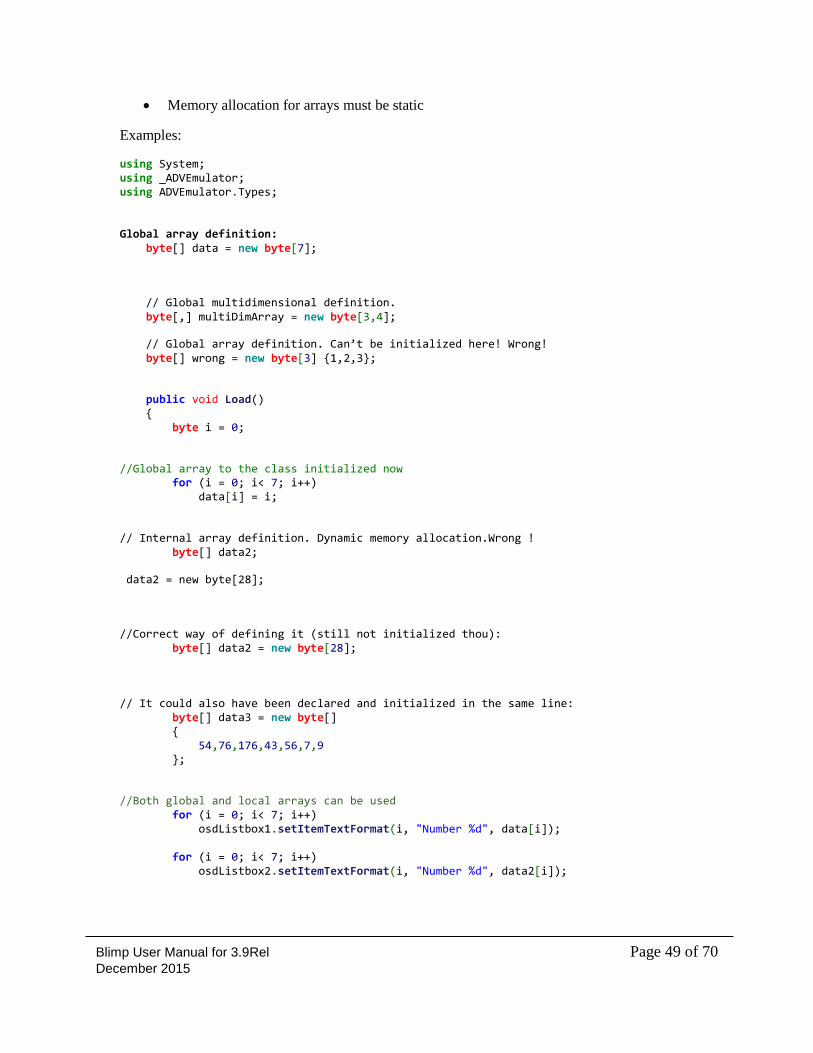
Memory allocation for arrays must be static
Examples:
using System; using _ADVEmulator; using ADVEmulator.Types; Global array definition: byte[] data = new byte[7];
// Global multidimensional definition. byte[,] multiDimArray = new byte[3,4];
// Global array definition. Can’t be initialized here! Wrong! byte[] wrong = new byte[3] {1,2,3};
public void Load() { byte i = 0;
//Global array to the class initialized now for (i = 0; i< 7; i++) data[i] = i;
// Internal array definition. Dynamic memory allocation.Wrong ! byte[] data2;
data2 = new byte[28];
//Correct way of defining it (still not initialized thou): byte[] data2 = new byte[28];
// It could also have been declared and initialized in the same line: byte[] data3 = new byte[] { 54,76,176,43,56,7,9 };
//Both global and local arrays can be used for (i = 0; i< 7; i++) osdListbox1.setItemTextFormat(i, "Number %d", data[i]); for (i = 0; i< 7; i++) osdListbox2.setItemTextFormat(i, "Number %d", data2[i]);
Blimp User Manual for 3.9Rel Page 50 of 70 December 2015
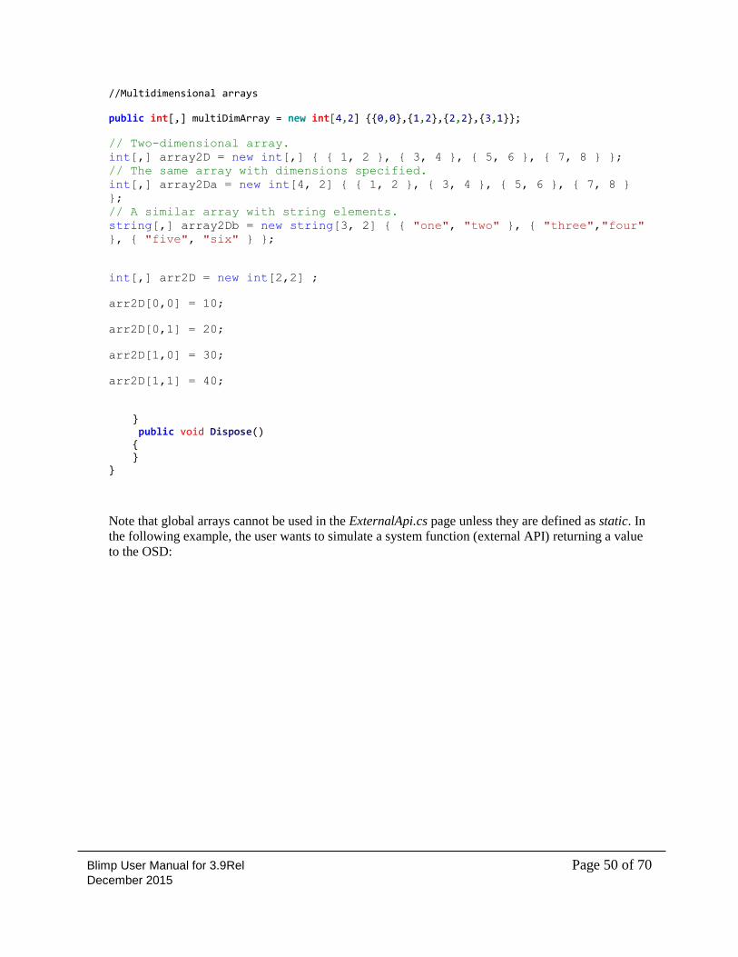
//Multidimensional arrays
public int[,] multiDimArray = new int[4,2] {{0,0},{1,2},{2,2},{3,1}};
// Two-dimensional array.
int[,] array2D = new int[,] { { 1, 2 }, { 3, 4 }, { 5, 6 }, { 7, 8 } };
// The same array with dimensions specified.
int[,] array2Da = new int[4, 2] { { 1, 2 }, { 3, 4 }, { 5, 6 }, { 7, 8 }
};
// A similar array with string elements.
string[,] array2Db = new string[3, 2] { { "one", "two" }, { "three","four"
}, { "five", "six" } };
int[,] arr2D = new int[2,2] ;
arr2D[0,0] = 10;
arr2D[0,1] = 20;
arr2D[1,0] = 30;
arr2D[1,1] = 40;
} public void Dispose() { } }
Note that global arrays cannot be used in the ExternalApi.cs page unless they are defined as static. In
the following example, the user wants to simulate a system function (external API) returning a value
to the OSD:
Blimp User Manual for 3.9Rel Page 51 of 70 December 2015
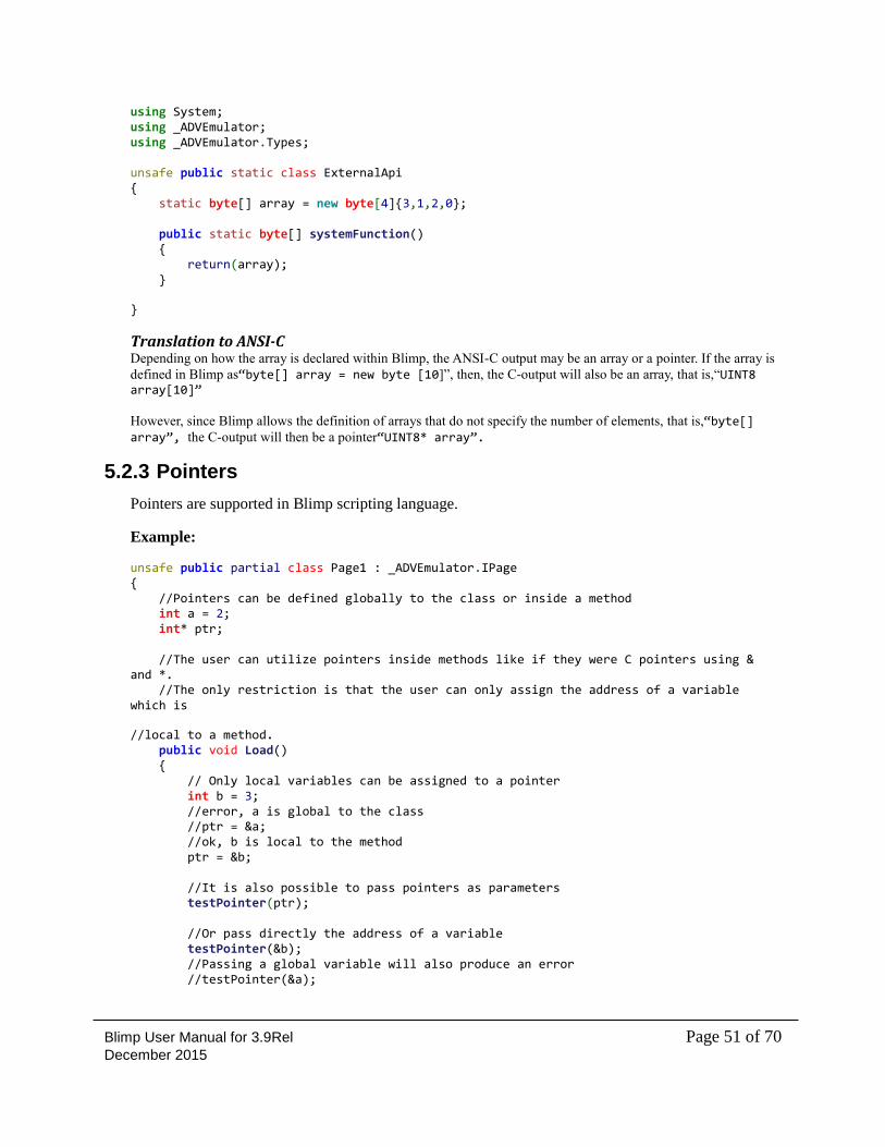
using System; using _ADVEmulator; using _ADVEmulator.Types; unsafe public static class ExternalApi { static byte[] array = new byte[4]{3,1,2,0}; public static byte[] systemFunction() { return(array); }
}
Translation to ANSI-C Depending on how the array is declared within Blimp, the ANSI-C output may be an array or a pointer. If the array is
defined in Blimp as“byte[] array = new byte [10]”, then, the C-output will also be an array, that is,“UINT8 array[10]” However, since Blimp allows the definition of arrays that do not specify the number of elements, that is,“byte[] array”, the C-output will then be a pointer“UINT8* array”.
5.2.3 Pointers
Pointers are supported in Blimp scripting language.
Example:
unsafe public partial class Page1 : _ADVEmulator.IPage { //Pointers can be defined globally to the class or inside a method int a = 2; int* ptr; //The user can utilize pointers inside methods like if they were C pointers using & and *. //The only restriction is that the user can only assign the address of a variable which is
//local to a method. public void Load() { // Only local variables can be assigned to a pointer int b = 3; //error, a is global to the class //ptr = &a; //ok, b is local to the method ptr = &b; //It is also possible to pass pointers as parameters testPointer(ptr); //Or pass directly the address of a variable testPointer(&b); //Passing a global variable will also produce an error //testPointer(&a);
Blimp User Manual for 3.9Rel Page 52 of 70 December 2015
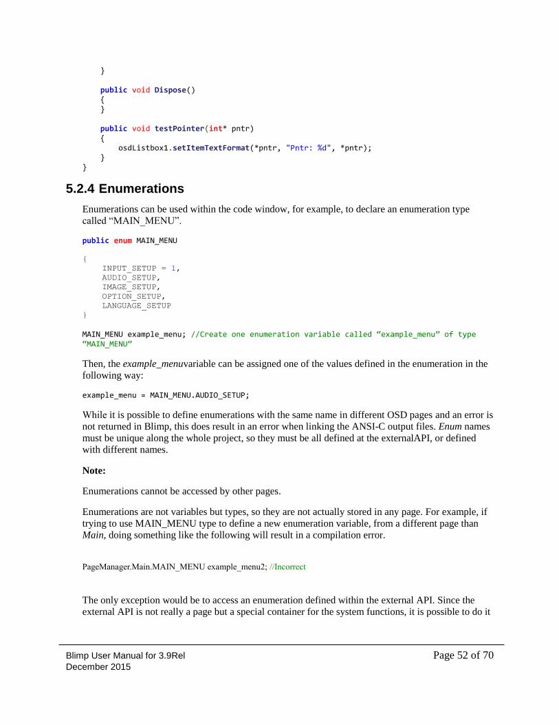
} public void Dispose() { } public void testPointer(int* pntr) { osdListbox1.setItemTextFormat(*pntr, "Pntr: %d", *pntr); } }
5.2.4 Enumerations
Enumerations can be used within the code window, for example, to declare an enumeration type
called “MAIN_MENU”.
public enum MAIN_MENU
{
INPUT_SETUP = 1,
AUDIO_SETUP,
IMAGE_SETUP,
OPTION_SETUP,
LANGUAGE_SETUP
} MAIN_MENU example_menu; //Create one enumeration variable called “example_menu” of type “MAIN_MENU”
Then, the example_menuvariable can be assigned one of the values defined in the enumeration in the
following way:
example_menu = MAIN_MENU.AUDIO_SETUP;
While it is possible to define enumerations with the same name in different OSD pages and an error is
not returned in Blimp, this does result in an error when linking the ANSI-C output files. Enum names
must be unique along the whole project, so they must be all defined at the externalAPI, or defined
with different names.
Note:
Enumerations cannot be accessed by other pages.
Enumerations are not variables but types, so they are not actually stored in any page. For example, if
trying to use MAIN_MENU type to define a new enumeration variable, from a different page than
Main, doing something like the following will result in a compilation error.
PageManager.Main.MAIN_MENU example_menu2; //Incorrect
The only exception would be to access an enumeration defined within the external API. Since the
external API is not really a page but a special container for the system functions, it is possible to do it
Blimp User Manual for 3.9Rel Page 53 of 70 December 2015
here. This may be useful for debugging the OSD-system interaction (for example, pass and return
system parameters defined as custom enumeration types), but it has no other use.
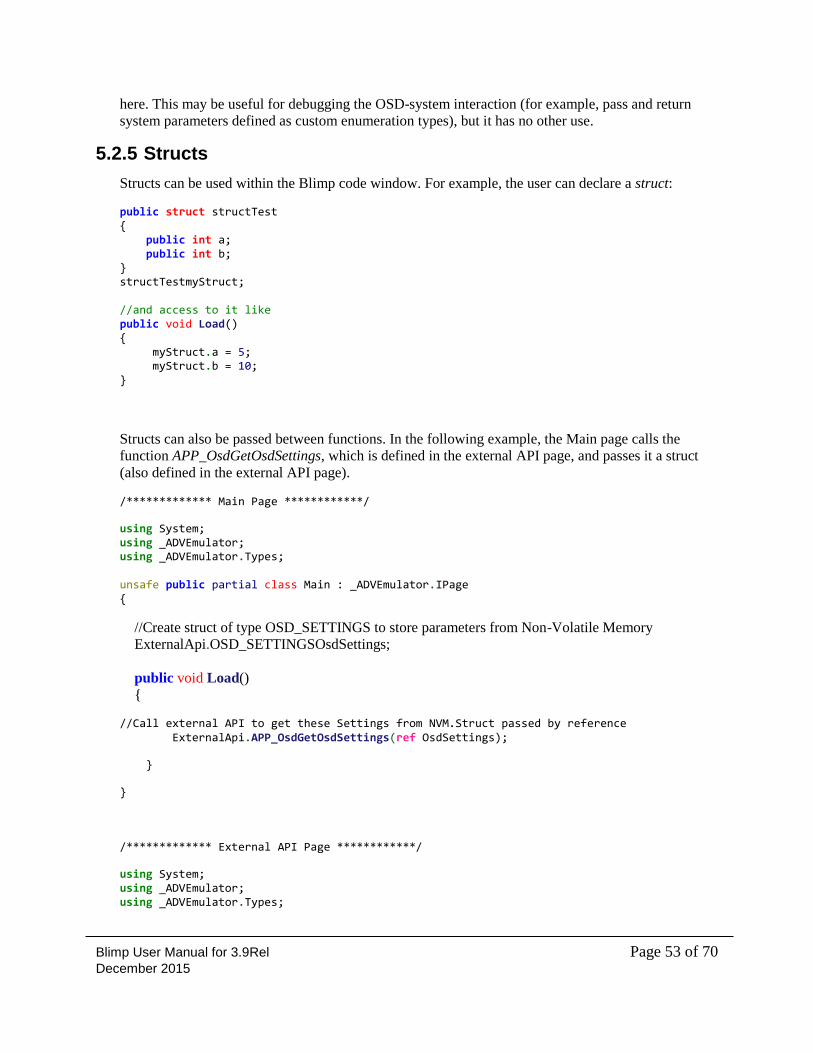
5.2.5 Structs
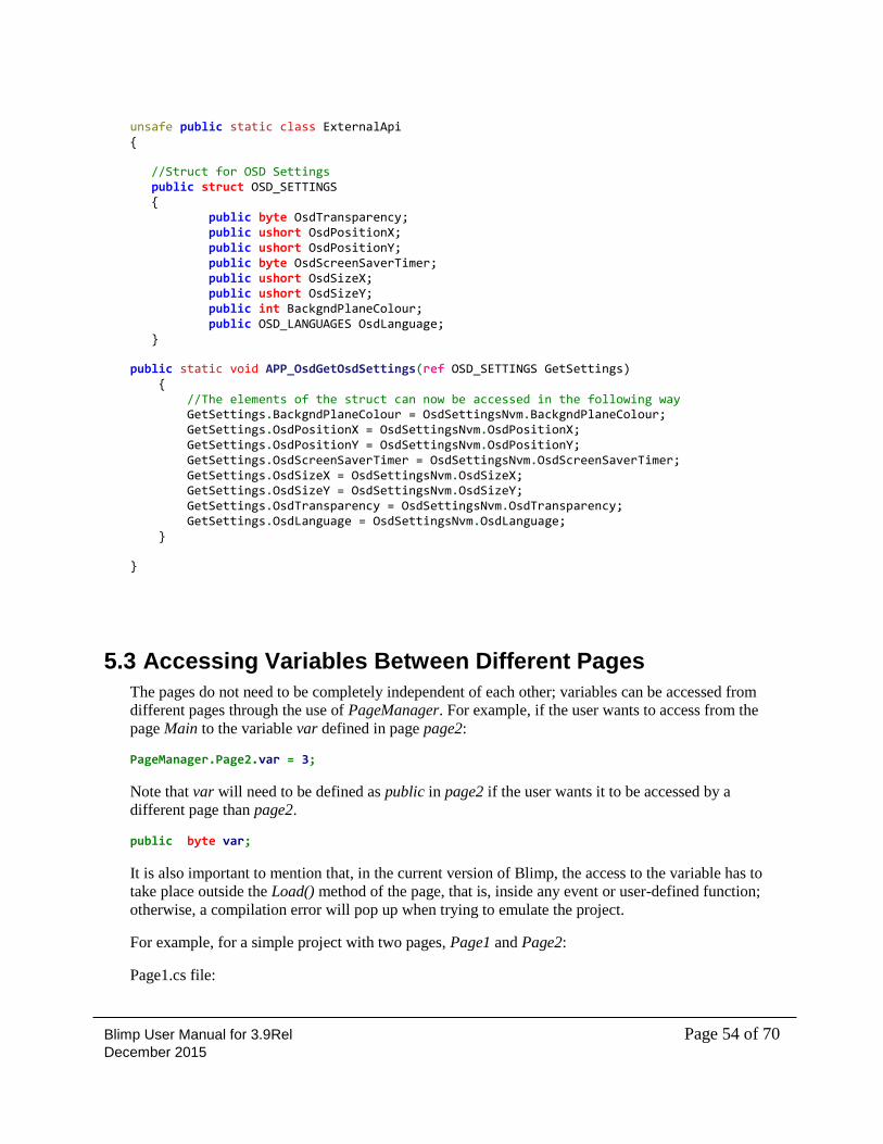
Structs can be used within the Blimp code window. For example, the user can declare a struct:
public struct structTest { public int a; public int b; } structTestmyStruct; //and access to it like public void Load() { myStruct.a = 5; myStruct.b = 10; }
Structs can also be passed between functions. In the following example, the Main page calls the
function APP_OsdGetOsdSettings, which is defined in the external API page, and passes it a struct
(also defined in the external API page).
/************* Main Page ************/
using System; using _ADVEmulator; using _ADVEmulator.Types; unsafe public partial class Main : _ADVEmulator.IPage {
//Create struct of type OSD_SETTINGS to store parameters from Non-Volatile Memory
ExternalApi.OSD_SETTINGSOsdSettings;
public void Load()
{
//Call external API to get these Settings from NVM.Struct passed by reference ExternalApi.APP_OsdGetOsdSettings(ref OsdSettings);
}
}
/************* External API Page ************/
using System; using _ADVEmulator; using _ADVEmulator.Types;
Blimp User Manual for 3.9Rel Page 54 of 70 December 2015
unsafe public static class ExternalApi {
//Struct for OSD Settings public struct OSD_SETTINGS { public byte OsdTransparency; public ushort OsdPositionX; public ushort OsdPositionY; public byte OsdScreenSaverTimer; public ushort OsdSizeX; public ushort OsdSizeY; public int BackgndPlaneColour; public OSD_LANGUAGES OsdLanguage; }
public static void APP_OsdGetOsdSettings(ref OSD_SETTINGS GetSettings) { //The elements of the struct can now be accessed in the following way GetSettings.BackgndPlaneColour = OsdSettingsNvm.BackgndPlaneColour; GetSettings.OsdPositionX = OsdSettingsNvm.OsdPositionX; GetSettings.OsdPositionY = OsdSettingsNvm.OsdPositionY; GetSettings.OsdScreenSaverTimer = OsdSettingsNvm.OsdScreenSaverTimer; GetSettings.OsdSizeX = OsdSettingsNvm.OsdSizeX; GetSettings.OsdSizeY = OsdSettingsNvm.OsdSizeY; GetSettings.OsdTransparency = OsdSettingsNvm.OsdTransparency; GetSettings.OsdLanguage = OsdSettingsNvm.OsdLanguage; }
}
5.3 Accessing Variables Between Different Pages
The pages do not need to be completely independent of each other; variables can be accessed from
different pages through the use of PageManager. For example, if the user wants to access from the
page Main to the variable var defined in page page2:
PageManager.Page2.var = 3;
Note that var will need to be defined as public in page2 if the user wants it to be accessed by a
different page than page2.
public byte var;
It is also important to mention that, in the current version of Blimp, the access to the variable has to
take place outside the Load() method of the page, that is, inside any event or user-defined function;
otherwise, a compilation error will pop up when trying to emulate the project.
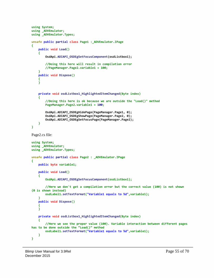
For example, for a simple project with two pages, Page1 and Page2:
Page1.cs file:
Blimp User Manual for 3.9Rel Page 55 of 70 December 2015
using System; using _ADVEmulator; using _ADVEmulator.Types; unsafe public partial class Page1 :_ADVEmulator.IPage { public void Load() { OsdApi.ADIAPI_OSDEgSetFocusComponent(osdListbox1); //Doing this here will result in compilation error //PageManager.Page2.variable1 = 100; } public void Dispose() { } private void osdListbox1_HighlightedItemChanged(Byte index) { //Doing this here is ok because we are outside the "Load()" method PageManager.Page2.variable1 = 100; OsdApi.ADIAPI_OSDEgHidePage(PageManager.Page1, 0); OsdApi.ADIAPI_OSDEgShowPage(PageManager.Page2, 0); OsdApi.ADIAPI_OSDEgSetFocusPage(PageManager.Page2); } }
Page2.cs file:
using System; using _ADVEmulator; using _ADVEmulator.Types; unsafe public partial class Page2 : _ADVEmulator.IPage { public byte variable1; public void Load() { OsdApi.ADIAPI_OSDEgSetFocusComponent(osdListbox1); //Here we don't get a compilation error but the correct value (100) is not shown (0 is shown instead) osdLabel1.setTextFormat("Variable1 equals to %d",variable1); } public void Dispose() { } private void osdListbox1_HighlightedItemChanged(Byte index) { //Here we see the proper value (100). Variable interaction between different pages has to be done outside the “Load()” method osdLabel1.setTextFormat("Variable1 equals to %d",variable1); } }
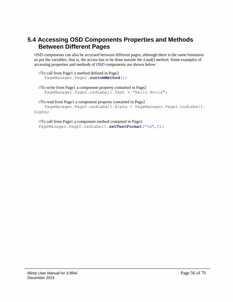
Blimp User Manual for 3.9Rel Page 56 of 70 December 2015
5.4 Accessing OSD Components Properties and Methods Between Different Pages
OSD components can also be accessed between different pages, although there is the same limitation
as per the variables, that is, the access has to be done outside the Load() method. Some examples of
accessing properties and methods of OSD components are shown below:
//To call from Page1 a method defined in Page2 PageManager.Page2.customMethod();
//To write from Page1 a component property contained in Page2 PageManager.Page2.osdLabel1.Text = "Hello World";
//To read from Page1 a component property contained in Page2 PageManager.Page2.osdLabel1.Alpha = PageManager.Page1.osdLabel1.
Alpha;
//To call from Page1 a component method contained in Page2
PageManager.Page2.osdLabel1.setTextFormat("%d",5);
Blimp User Manual for 3.9Rel Page 57 of 70 December 2015
6 Building an OSD Project This chapter provides the information required in order to build an OSD project.
The following topics are covered:
“Blimp Output Files” on page 57
6.1 Blimp Output Files
A series of files are used and generated by Blimp when creating and compiling a project; these are the
files located in the Release folder, within the project directory.
The tool generates one .c and .h file for each page being used. These files are named blimp_<page
name>.c, blimp_<page name.h>, and so on. There are also two files called blimp_resource.c and
blimp_resource.h, which define the entry point to the OSD, setting the resolution, which page would
be shown first, and so on. Only the .c and .h files are required to be imported into the MCU project
along with the OSD firmware libraries.
The ddr2_dump.bin file is the ROM image which needs to be stored in the flash memory of the
system so it can be accessed later by the ADVXXXX. It includes all the graphical resources (images,
fonts and keyboard templates) plus all the language strings. To reduce the size of the file, Blimp
applies a compression algorithm to it so space can be saved within the external flash memory. The
ADVXXXX applies the same algorithm when reading the data back and storing it on the DDR2
memory.
When the memory dump is compiled, Blimp calculates a CRC32 IEEE 802.3 for this .bin file, which
will be shown in the console.
Example:
Memory dump completed. CRC: 0xfdd51198
The CRC can be used to check the integrity of the file when loading it into flash, or reading the file from flash from
MCU.
The user can implement a CRC32 routine in the MCU, which checks for errors within the data being
stored in the SPI flash by comparing the result of the function with the CRC provided by Blimp. The
rest of the files contained on this folder are used by the emulator within Blimp.
For each page on the design, there is one .cs file which contains what would be a parsed version of
the scripting defined in the code window (which can be found in the main folder of the project). The
<page name>..cs files contain information regarding how the components were defined on the design
window, that is, how they look by default before being affected by any instruction of the scripting
code.
There is also a series of other .cs files:
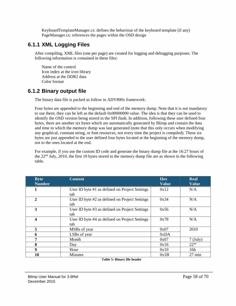
Blimp User Manual for 3.9Rel Page 58 of 70 December 2015
KeyboardTemplateManager.cs: defines the behaviour of the keyboard template (if any)
PageManager.cs: references the pages within the OSD design
6.1.1 XML Logging Files
After compiling, XML files (one per page) are created for logging and debugging purposes. The
following information is contained in these files:
Name of the control
Icon index at the icon library
Address at the DDR2 data
Color format
6.1.2 Binary output file
The binary data file is packed as follow in ADV800x framework:
Four bytes are appended to the beginning and end of the memory dump. Note that it is not mandatory
to use them; they can be left as the default 0x00000000 value. The idea is that they can be used to
identify the OSD version being stored in the SPI flash. In addition, following these user defined four
bytes, there are another six bytes which are automatically generated by Blimp and contain the data
and time in which the memory dump was last generated (note that this only occurs when modifying
any graphical, constant string, or font resources, not every time the project is compiled). These six
bytes are just appended to the user defined four bytes located at the beginning of the memory dump,
not to the ones located at the end.
For example, if you use the custom ID code and generate the binary dump file at the 16:27 hours of
the 22nd July, 2010, the first 10 bytes stored in the memory dump file are as shown in the following
table.
Byte
Number
Content Hex
Value
Real
Value
1 User ID byte #1 as defined on Project Settings
tab
0x12 N/A
2 User ID byte #2 as defined on Project Settings
tab
0x34 N/A
3 User ID byte #3 as defined on Project Settings
tab
0x56 N/A
4 User ID byte #4 as defined on Project Settings
tab
0x78 N/A
5 MSBs of year 0x07 2010
6 LSBs of year 0xDA
7 Month 0x07 7 (July)
8 Day 0x16 22nd
9 Hour 0x10 16h
10 Minutes 0x1B 27 min Table 5: Binary file header
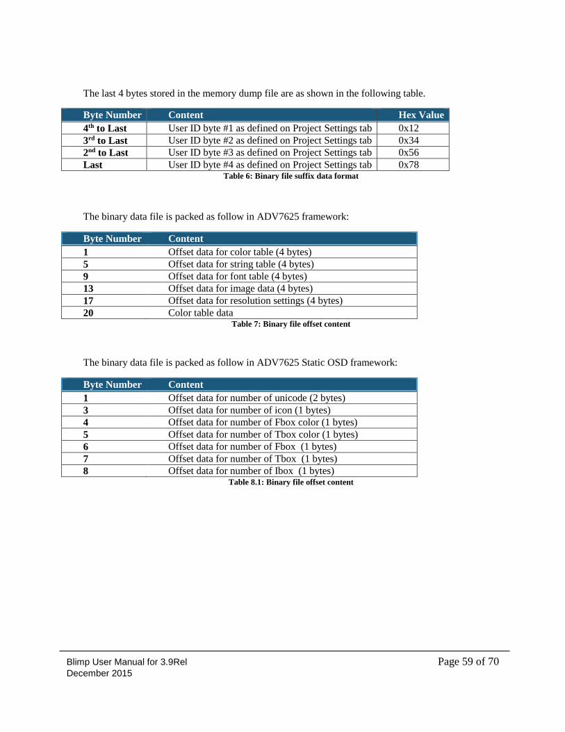
Blimp User Manual for 3.9Rel Page 59 of 70 December 2015
The last 4 bytes stored in the memory dump file are as shown in the following table.
Byte Number Content Hex Value
4th to Last User ID byte #1 as defined on Project Settings tab 0x12
3rd to Last User ID byte #2 as defined on Project Settings tab 0x34
2nd to Last User ID byte #3 as defined on Project Settings tab 0x56
Last User ID byte #4 as defined on Project Settings tab 0x78 Table 6: Binary file suffix data format
The binary data file is packed as follow in ADV7625 framework:
Byte Number Content
1 Offset data for color table (4 bytes)
5 Offset data for string table (4 bytes)
9 Offset data for font table (4 bytes)
13 Offset data for image data (4 bytes)
17 Offset data for resolution settings (4 bytes)
20 Color table data Table 7: Binary file offset content
The binary data file is packed as follow in ADV7625 Static OSD framework:
Byte Number Content
1 Offset data for number of unicode (2 bytes)
3 Offset data for number of icon (1 bytes)
4 Offset data for number of Fbox color (1 bytes)
5 Offset data for number of Tbox color (1 bytes)
6 Offset data for number of Fbox (1 bytes)
7 Offset data for number of Tbox (1 bytes)
8 Offset data for number of Ibox (1 bytes) Table 8.1: Binary file offset content
Blimp User Manual for 3.9Rel Page 60 of 70 December 2015
7 Emulating and Debugging an OSD Project This chapter provides the information required to emulate and debug an OSD project.
7.1 Emulator Window
The emulator can be accessed through Debug → Emulate (or by pressing F5). This compiles the
project, passes its result to the linker and, if there are no errors, launches the emulator window which
allows you to see how the OSD will look and behave to the user inputs.
The emulator consists of a host application which captures keys, and provides some basic timing to
generate 60 Hz video. It interfaces the compiled C firmware (that is, the ANSI-C code output from
Blimp plus the OSD libraries provided by ADI) to display the OSD. In turn, the compiled C firmware
interfaces to a hardware emulator which matches the behaviour of the ADVXXXX. The
communication between the firmware and the hardware emulator is done by SPI transfers as it is done
in the real system.
This implementation allows the Blimp emulator to mimic accurately the performance of the OSD
once downloaded into the custom system board, providing you with powerful software debug tool
without the need for any hardware.
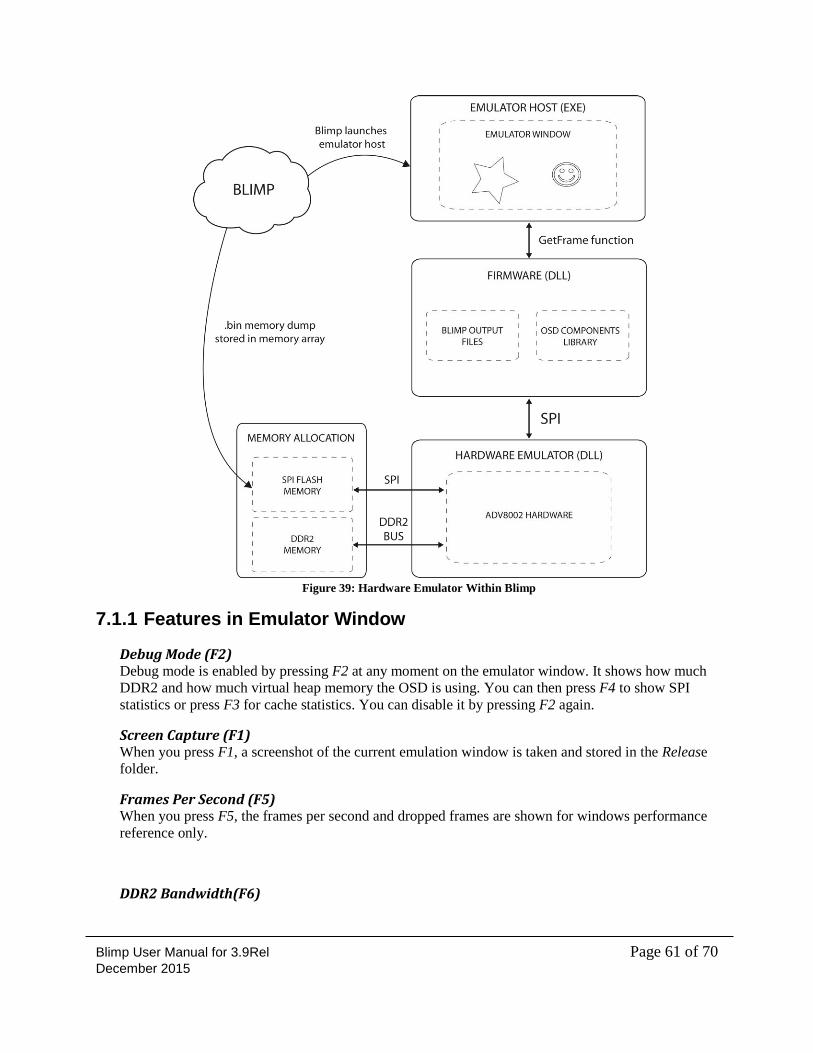
Blimp User Manual for 3.9Rel Page 61 of 70 December 2015
Figure 39: Hardware Emulator Within Blimp
7.1.1 Features in Emulator Window
Debug Mode (F2) Debug mode is enabled by pressing F2 at any moment on the emulator window. It shows how much
DDR2 and how much virtual heap memory the OSD is using. You can then press F4 to show SPI
statistics or press F3 for cache statistics. You can disable it by pressing F2 again.
Screen Capture (F1) When you press F1, a screenshot of the current emulation window is taken and stored in the Release
folder.
Frames Per Second (F5) When you press F5, the frames per second and dropped frames are shown for windows performance
reference only.
DDR2 Bandwidth(F6)
Blimp User Manual for 3.9Rel Page 62 of 70 December 2015
When you press F6, the DDR2 bandwidth per line is shown by the red color bars.
7.1.2 Standalone Emulator
Blimp allows visualizing the emulator window without the need for having Blimp installed on the
computer. Within the Release folder, Blimp outputs a series of files, which allows launching a
standalone emulator window.
8 Integrating OSD into an MCU Project This chapter provides the information required to integrate the OSD into an MCU project.
The following topics are covered:
“Porting Code for OSD Integration into MCU” on page 62
“Functions to Implement” on page 62
“Initialization” on page 63
“Run Time” on page 64
“External APIs” on page 65
“Programming flash” on page 66
8.1 Porting Code for OSD Integration into MCU
Follow these steps to port code for the integration of the OSD into MCU.
Provide the SPI reading/writing functions, and the timer interrupt service routine.
Link the SPI functions and call one API function to initialize the OSD library.
Press the push button or IR remote controller to send the key code to OSD.
8.2 Functions to Implement
8.2.1 SPI Reading/Writing Functions
Syntax in ADV800x:
UINT32 spi_read (UINT32 devAddr, UINT32 regAddr, UINT8 *databuf,
UINT32 cnt, UINT8 endian);
UINT32 spi_write (UINT32 devAddr, UINT32 regAddr, UINT8 *databuf,
UINT32 cnt, UINT8 endian);
Syntax in ADV7625 / ADV7625 Static OSD :
voidSpiTransfer (UINT8 *wrDataBuf, UINT32 wrCnt, UINT8 *rdDataBuf, UINT32 rdCnt);
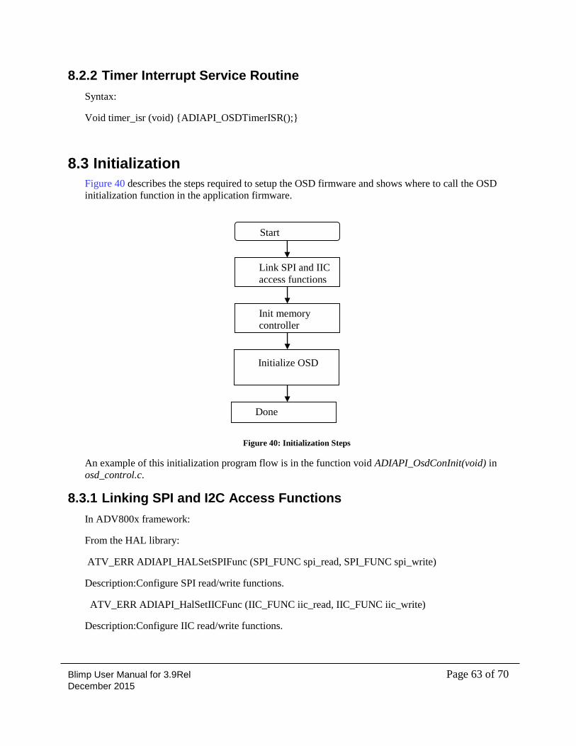
Blimp User Manual for 3.9Rel Page 63 of 70 December 2015
8.2.2 Timer Interrupt Service Routine
Syntax:
Void timer_isr (void) {ADIAPI_OSDTimerISR();}
8.3 Initialization
Figure 40 describes the steps required to setup the OSD firmware and shows where to call the OSD
initialization function in the application firmware.
Figure 40: Initialization Steps
An example of this initialization program flow is in the function void ADIAPI_OsdConInit(void) in
osd_control.c.
8.3.1 Linking SPI and I2C Access Functions
In ADV800x framework:
From the HAL library:
ATV_ERR ADIAPI_HALSetSPIFunc (SPI_FUNC spi_read, SPI_FUNC spi_write)
Description:Configure SPI read/write functions.
ATV_ERR ADIAPI_HalSetIICFunc (IIC_FUNC iic_read, IIC_FUNC iic_write)
Description:Configure IIC read/write functions.
Start
Link SPI and IIC
access functions
Init memory
controller
Initialize OSD
Done

Blimp User Manual for 3.9Rel Page 64 of 70 December 2015
In ADV7625 / ADV7625 Static OSD framework:
void DriverApi_registerSpiI2cHal(SPI_TRANSFER_FUNC spi_xfer, I2C_BYTE_WR_FUNC
i2c_wr, I2C_BYTE_RD_FUNC i2c_rd, I2C_WORD_RD_FUNC i2c_rdword,
SPI_SET_SLAVE spi_slave)
Remark: In osd_control.c, the IIC access function has already been linked within a previous
initialization call.
8.3.2 Initialize OSD
The call to ADIAPI_OSDEgInit in ADV800x framework:
Controls DMA to read the image and font resource from flash to DDR2.Initializes the OSD
graphic engine register component, initializes the hardware, and creates components
The call to OSDAPI_OSDApiInit in ADV7625 / ADV7625 Static OSD framework:
Initializes the OSD graphic engine register component, initializes the hardware, and creates
components
8.4 Run Time
8.4.1 Process Interrupts
The ADIAPI_OSDProcessInterrupts function must be called periodically in order to ensure the proper
timing of timers and the refresh of the OSD display.
The function may also be called if a critical interrupt needs to be handled in time within the OSD.
8.4.2 Send Key Presses Events
When a key press is detected from the input source, the ADIAPI_ OSDEgPostKeyMsg function must
be called to send the key press to the Blimp OSD.
Example:
switch (key)
{
case KEYPAD_LEFT:
{
ADIAPI_OSDEgGetMutex();
ADIAPI_OSDEgPostKeyMsg (KEYBOARD_LEFT);
ADIAPI_OSDEgReleaseMutex ();
break;
Blimp User Manual for 3.9Rel Page 65 of 70 December 2015
}
}
......
Note: GetMutex and ReleaseMutex present only in ADV800x.
8.5 External APIs
The external API page can be used to define the interface between the OSD and the rest of the
system, allowing the OSD-system interface to be defined completely (except for the actual external
system functions implementation that are obviously defined in the application side) within the OSD
tool.
A new code window tab pops up when you select Project →External api.You can list here all the
external functions prototypes that can be called within the OSD code. Once the OSD is merged with
the rest of the application code, it isa case of linking these declarations with the system functions.
However, in order to be able to simulate within the emulator the behaviour of these external functions
before the OSD is running within the real system, it is also possible to add code to these external
functions, for example, writing that the function returns some value after a certain time interval. The
code written in these functions is translated into ANSI-C and sent to the emulator, which runs it.
In the following example, an external function named changeHDMIInputis added to the external API,
and then called within the OSD code.
Enternal API code:
public static class ExternalApi
{
public static bool changeHDMIInput(int sampleParameter)
{
return(true); //Simulated return value
}
}
OSDPage code:
public void Load()
{
osdListbox1.ItemText[0] = "Select HDMI Input 1";
osdListbox1.ItemText[1] = "Select HDMI Input 2";
osdListbox1.ItemText[2] = "Select HDMI Input 3";
OsdApi.ADIAPI_OSDEgSetFocusComponent(osdListbox1);
}
private void osdListbox1_SelectedItemChanged(Byte index,BooleannewStatus)
{
bool error;
error = ExternalApi.changeHDMIInput(index+1);
if (error)
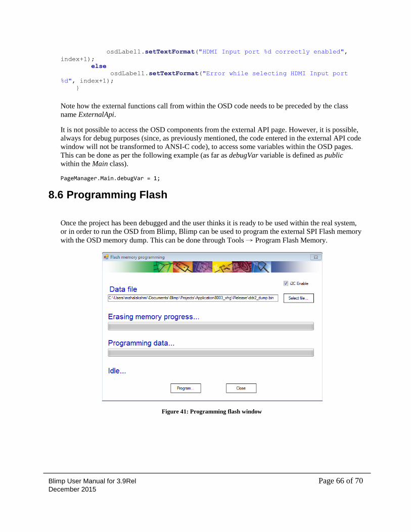
Blimp User Manual for 3.9Rel Page 66 of 70 December 2015
osdLabel1.setTextFormat("HDMI Input port %d correctly enabled",
index+1);
else
osdLabel1.setTextFormat("Error while selecting HDMI Input port
%d", index+1);
}
Note how the external functions call from within the OSD code needs to be preceded by the class
name ExternalApi.
It is not possible to access the OSD components from the external API page. However, it is possible,
always for debug purposes (since, as previously mentioned, the code entered in the external API code
window will not be transformed to ANSI-C code), to access some variables within the OSD pages.
This can be done as per the following example (as far as debugVar variable is defined as public
within the Main class).
PageManager.Main.debugVar = 1;
8.6 Programming Flash
Once the project has been debugged and the user thinks it is ready to be used within the real system,
or in order to run the OSD from Blimp, Blimp can be used to program the external SPI Flash memory
with the OSD memory dump. This can be done through Tools → Program Flash Memory.
Figure 41: Programming flash window
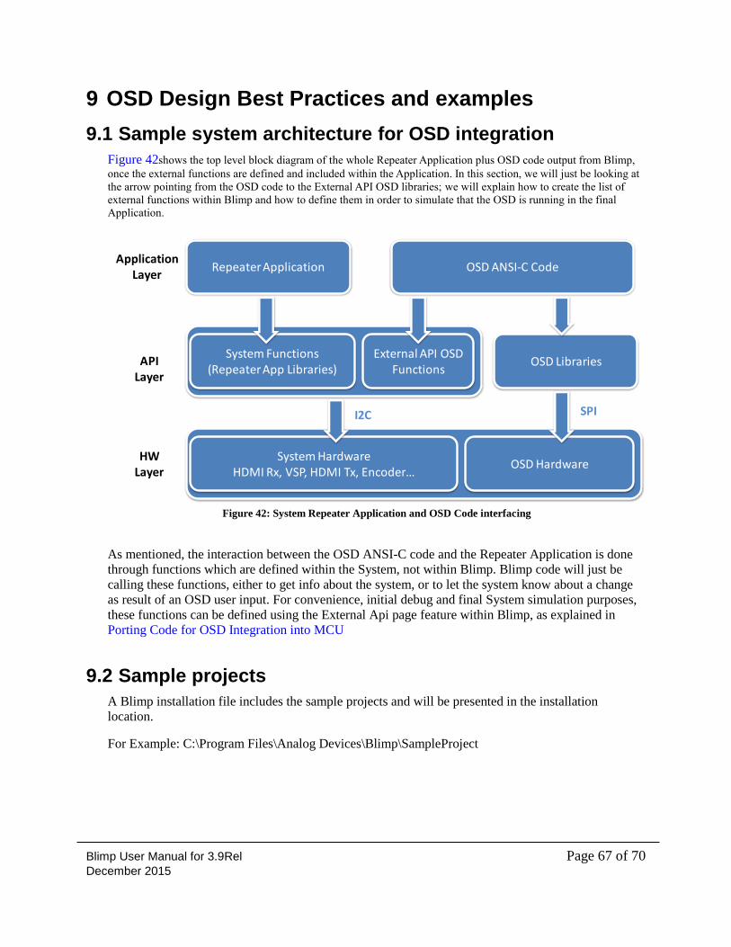
Blimp User Manual for 3.9Rel Page 67 of 70 December 2015
9 OSD Design Best Practices and examples
9.1 Sample system architecture for OSD integration
Figure 42shows the top level block diagram of the whole Repeater Application plus OSD code output from Blimp,
once the external functions are defined and included within the Application. In this section, we will just be looking at
the arrow pointing from the OSD code to the External API OSD libraries; we will explain how to create the list of
external functions within Blimp and how to define them in order to simulate that the OSD is running in the final
Application.
Figure 42: System Repeater Application and OSD Code interfacing
As mentioned, the interaction between the OSD ANSI-C code and the Repeater Application is done
through functions which are defined within the System, not within Blimp. Blimp code will just be
calling these functions, either to get info about the system, or to let the system know about a change
as result of an OSD user input. For convenience, initial debug and final System simulation purposes,
these functions can be defined using the External Api page feature within Blimp, as explained in
Porting Code for OSD Integration into MCU
9.2 Sample projects
A Blimp installation file includes the sample projects and will be presented in the installation
location.
For Example: C:\Program Files\Analog Devices\Blimp\SampleProject
Repeater Application
System Functions(Repeater App Libraries)
OSD ANSI-C Code
System HardwareHDMI Rx, VSP, HDMI Tx, Encoder…
OSD Hardware
OSD LibrariesExternal API OSD
Functions
ApplicationLayer
APILayer
HWLayer
I2C SPI
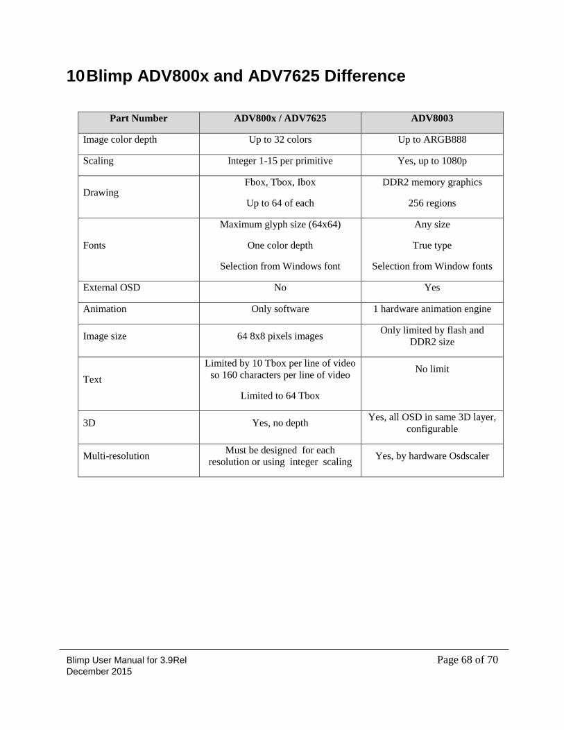
Blimp User Manual for 3.9Rel Page 68 of 70 December 2015
10 Blimp ADV800x and ADV7625 Difference
Part Number ADV800x / ADV7625 ADV8003
Image color depth Up to 32 colors Up to ARGB888
Scaling Integer 1-15 per primitive Yes, up to 1080p
Drawing Fbox, Tbox, Ibox
Up to 64 of each
DDR2 memory graphics
256 regions
Fonts
Maximum glyph size (64x64)
One color depth
Selection from Windows font
Any size
True type
Selection from Window fonts
External OSD No Yes
Animation Only software 1 hardware animation engine
Image size 64 8x8 pixels images Only limited by flash and
DDR2 size
Text
Limited by 10 Tbox per line of video
so 160 characters per line of video
Limited to 64 Tbox
No limit
3D Yes, no depth Yes, all OSD in same 3D layer,
configurable
Multi-resolution Must be designed for each
resolution or using integer scaling Yes, by hardware Osdscaler
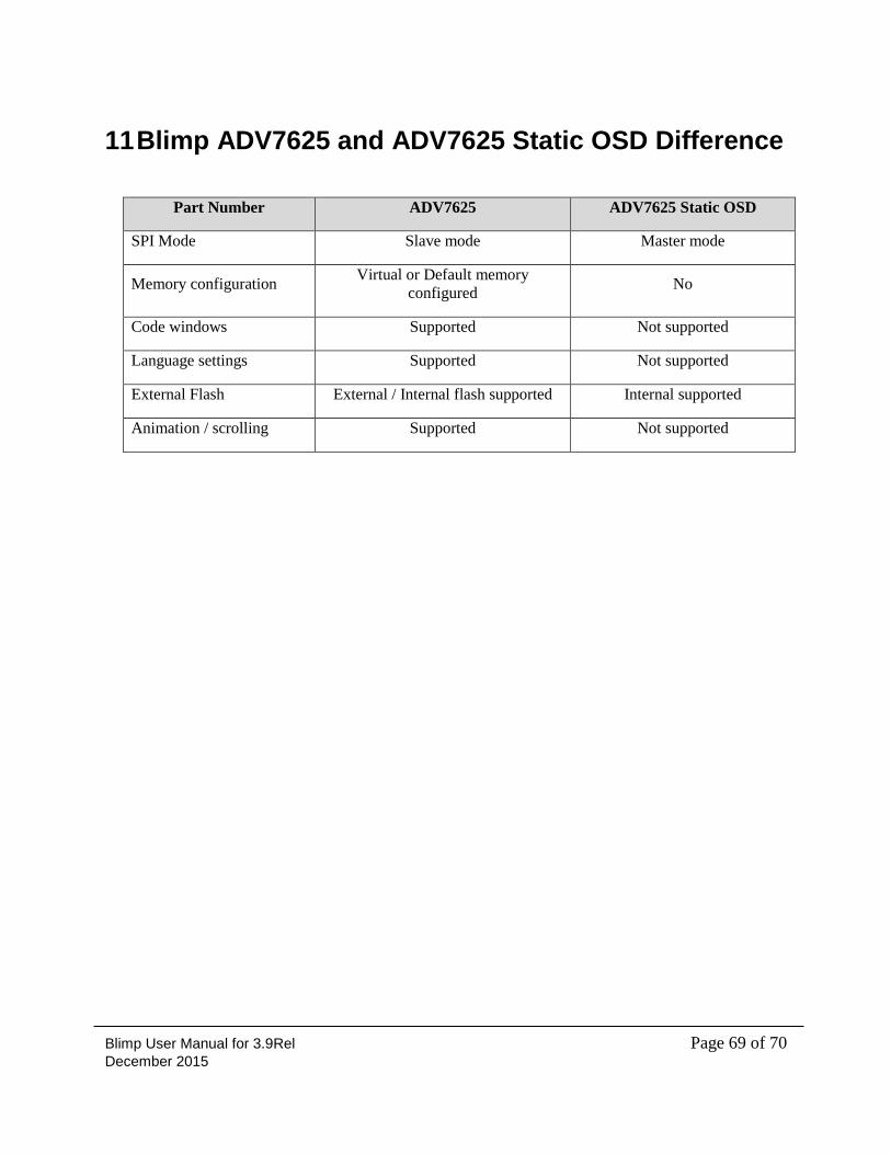
Blimp User Manual for 3.9Rel Page 69 of 70 December 2015
11 Blimp ADV7625 and ADV7625 Static OSD Difference
Part Number ADV7625 ADV7625 Static OSD
SPI Mode Slave mode Master mode
Memory configuration Virtual or Default memory
configured No
Code windows Supported Not supported
Language settings Supported Not supported
External Flash External / Internal flash supported Internal supported
Animation / scrolling Supported Not supported
Blimp User Manual for 3.9Rel Page 70 of 70 December 2015
Appendix A: Blimp Libraries and Licenses The Blimp tool uses the following libraries:
TreeViewAdv - Copyright (c) 2009, AndreyGliznetsov ([email protected])
http://sourceforge.net/projects/treeviewadv/
DockPanelSuite - Copyright (c) 2007, WeifenLuo (email: [email protected])
http://sourceforge.net/projects/dockpanelsuite/
IP Components
http://www.codeproject.com/KB/miscctrl/IPToolbox.aspx
AvalontEdit, NRefactory, SharpDevelop.Dom - Copyright (c) 2010, Ic#code
(http://www.icsharpcode.net)
Log4net (log4net.dll) - Copyright (c) 2010, Apache foundation
http://logging.apache.org/log4net/
Mono Cecil (Mono.Cecil.dll) - Mono Cecil - Copyright (c) 2010, Novell
http://www.mono-project.com/Cecil
FreeType Project 2006-Jan-27- Copyright 1996-2002, 2006 by David Turner, Robert Wilhelm, and
Werner Lemberg
www.freetype.org