Embed Size (px)
Citation preview

BlitzRCWorks P-40N
SPECIFICATION Wingspan:1100mm (43.3”)
Flying weight:1300/1400g (45/49oz) 3/4 cell Length:1000mm (39.3”)
Servos:7 x 9g type (2 aileron, 2 flap, elevator, rudder, bomb system) Motor: Banana Hobby
3536 900Kv brushless outrunner
ESC: Banana Hobby 45amp
Battery: 2200mah 3S 60-65C or 2200mah 4S 25-30C
Channels: 6-7 required (7 if using included bomb system)
- This is a radio controlled flying model and as such must always be flown with
caution and care. This is not a toy.
- The P-40 is designed for intermediate to advanced pilots.
- Always exercise great caution when using the recommended battery to power
this product. For full safety notes and operating procedures, please see
information provided by your battery supplier.
- Take great care when connecting/disconnecting the battery. See battery
supplier for full safety procedures.
- Never power up the model in confined spaces and always keep the prop clear
of obstructions.
- This product is not a toy. Children must be accompanied by an adult at all times
if operating this product.
- Only fly this model in an open area away from crowds, people, buildings, tree's,
power lines and obstructions.
- Always put safety first when operating this model and consider the warningsstated above.
- The supplier/manufacturer accepts no responsibility for damage or injury
caused through the use of the product. Not suitable for children under the age
of 14. THIS IS NOT A TOY.
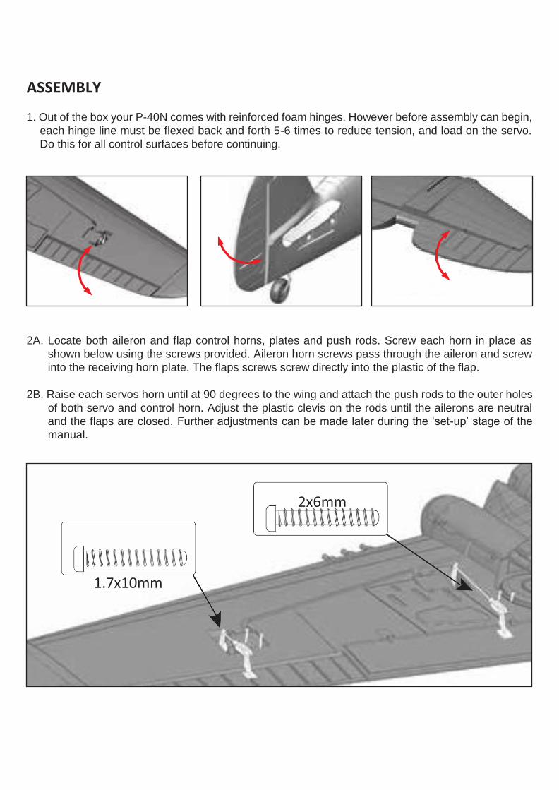
2x6mm
1.7x10mm
ASSEMBLY
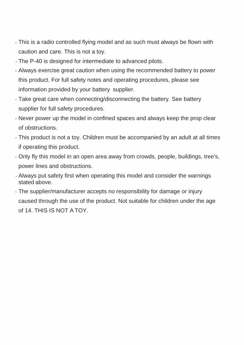
1. Out of the box your P-40N comes with reinforced foam hinges. However before assembly can begin,
each hinge line must be flexed back and forth 5-6 times to reduce tension, and load on the servo.
Do this for all control surfaces before continuing.
2A. Locate both aileron and flap control horns, plates and push rods. Screw each horn in place as
shown below using the screws provided. Aileron horn screws pass through the aileron and screw
into the receiving horn plate. The flaps screws screw directly into the plastic of the flap.
2B. Raise each servos horn until at 90 degrees to the wing and attach the push rods to the outer holes
of both servo and control horn. Adjust the plastic clevis on the rods until the ailerons are neutral
and the flaps are closed. Further adjustments can be made later during the ‘set-up’ stage of the
manual.
3x8mm
2.6x6mm
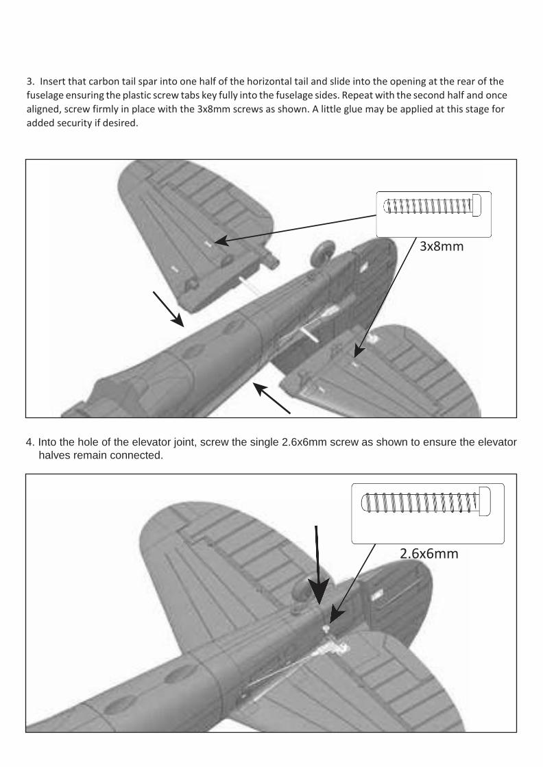
3. Insert that carbon tail spar into one half of the horizontal tail and slide into the opening at the rear of the
fuselage ensuring the plastic screw tabs key fully into the fuselage sides. Repeat with the second half and once
aligned, screw firmly in place with the 3x8mm screws as shown. A little glue may be applied at this stage for
added security if desired.
4. Into the hole of the elevator joint, screw the single 2.6x6mm screw as shown to ensure the elevator
halves remain connected.
2.7x30mm
2.7x25mm
2.6x8mm
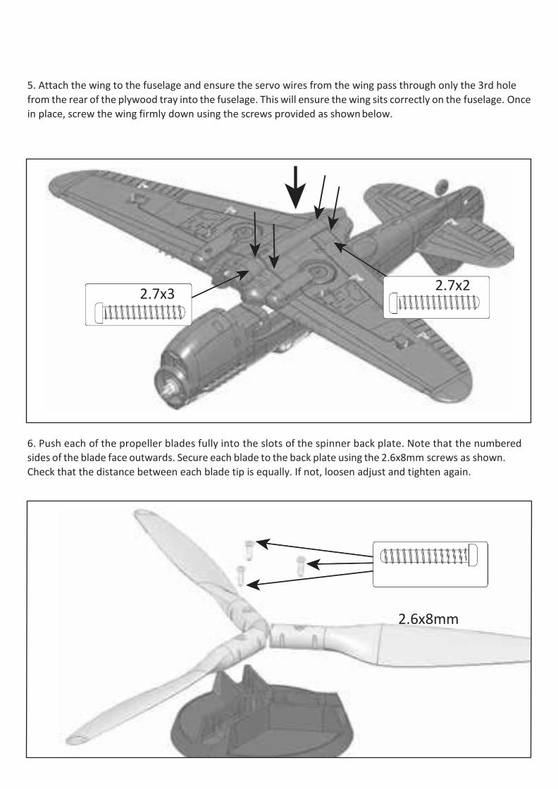
5. Attach the wing to the fuselage and ensure the servo wires from the wing pass through only the 3rd hole
from the rear of the plywood tray into the fuselage. This will ensure the wing sits correctly on the fuselage. Once
in place, screw the wing firmly down using the screws provided as shown below.
6. Push each of the propeller blades fully into the slots of the spinner back plate. Note that the numbered
sides of the blade face outwards. Secure each blade to the back plate using the 2.6x8mm screws as shown.
Check that the distance between each blade tip is equally. If not, loosen adjust and tighten again.
3x50mm bolt
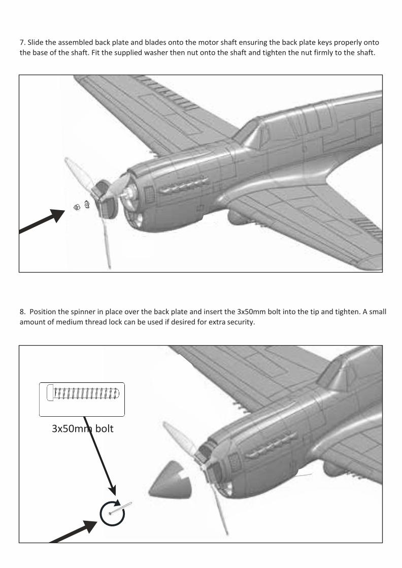
7. Slide the assembled back plate and blades onto the motor shaft ensuring the back plate keys properly onto
the base of the shaft. Fit the supplied washer then nut onto the shaft and tighten the nut firmly to the shaft.
8. Position the spinner in place over the back plate and insert the 3x50mm bolt into the tip and tighten. A small
amount of medium thread lock can be used if desired for extra security.
2x20mm
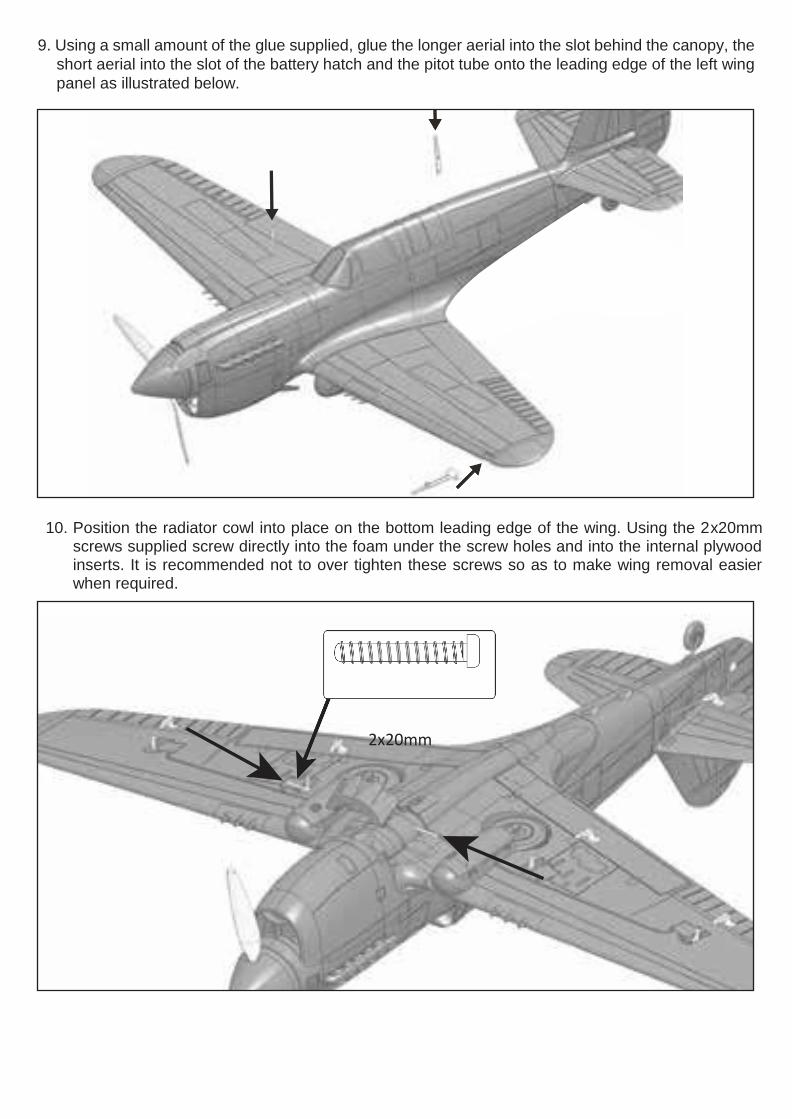
9. Using a small amount of the glue supplied, glue the longer aerial into the slot behind the canopy, the
short aerial into the slot of the battery hatch and the pitot tube onto the leading edge of the left wing
panel as illustrated below.
10. Position the radiator cowl into place on the bottom leading edge of the wing. Using the 2x20mmscrews supplied screw directly into the foam under the screw holes and into the internal plywoodinserts. It is recommended not to over tighten these screws so as to make wing removal easierwhen required.
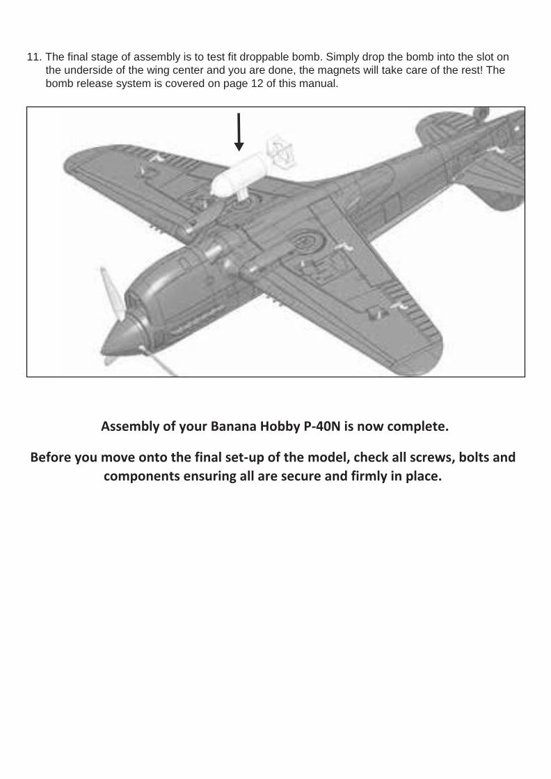
11. The final stage of assembly is to test fit droppable bomb. Simply drop the bomb into the slot on
the underside of the wing center and you are done, the magnets will take care of the rest! The
bomb release system is covered on page 12 of this manual.
Assembly of your Banana Hobby P-40N is now complete.
Before you move onto the final set-up of the model, check all screws, bolts and
components ensuring all are secure and firmly in place.
1. With your receiver installed and all servos plugged into their corresponding channels, connect the flight
battery to the ESC to power up the electronics. With the model now armed, ensure all servos are
centered and all control surfaces are level. If not, adjust by turning the control clevis’s by hand
accordingly until the control surfaces are level as shown.
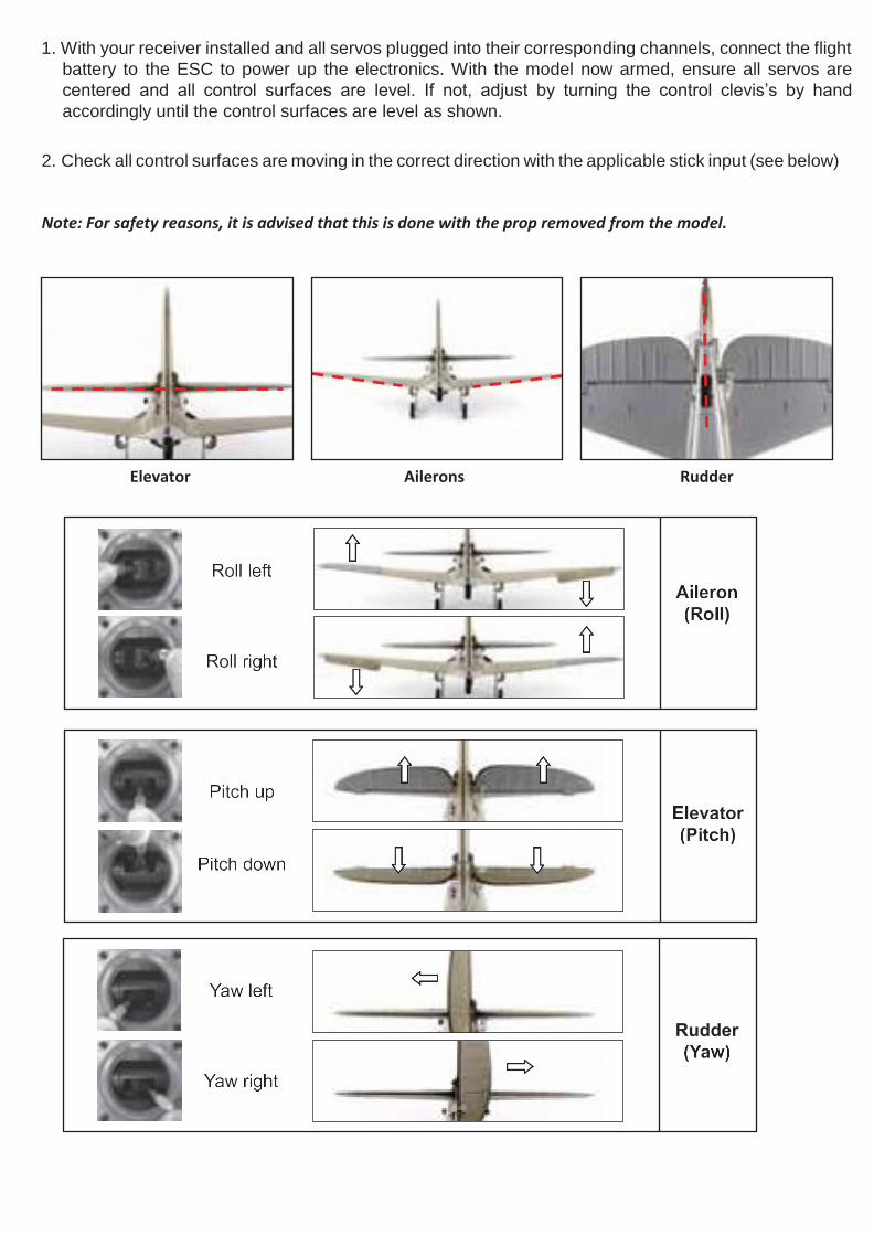
2. Check all control surfaces are moving in the correct direction with the applicable stick input (see below)
Note: For safety reasons, it is advised that this is done with the prop removed from the model.
Elevator Ailerons Rudder
25mm/1” 60mm/2.3”
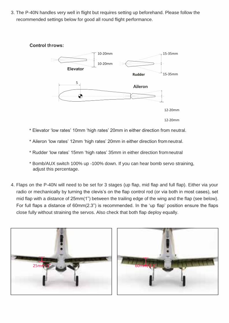
3. The P-40N handles very well in flight but requires setting up beforehand. Please follow the
recommended settings below for good all round flight performance.
10-20mm
10-20mm
Rudder
15-35mm
15-35mm
12-20mm
12-20mm
* Elevator ‘low rates’ 10mm ‘high rates’ 20mm in either direction from neutral.
* Aileron ‘low rates’ 12mm ‘high rates’ 20mm in either direction from neutral.
* Rudder ‘low rates’ 15mm ‘high rates’ 35mm in either direction from neutral
* Bomb/AUX switch 100% up -100% down. If you can hear bomb servo straining,
adjust this percentage.
4. Flaps on the P-40N will need to be set for 3 stages (up flap, mid flap and full flap). Either via your
radio or mechanically by turning the clevis’s on the flap control rod (or via both in most cases), set
mid flap with a distance of 25mm(1”) between the trailing edge of the wing and the flap (see below).
For full flaps a distance of 60mm(2.3”) is recommended. In the ‘up flap’ position ensure the flaps
close fully without straining the servos. Also check that both flap deploy equally.
55-65mm
Position 1 Position 2
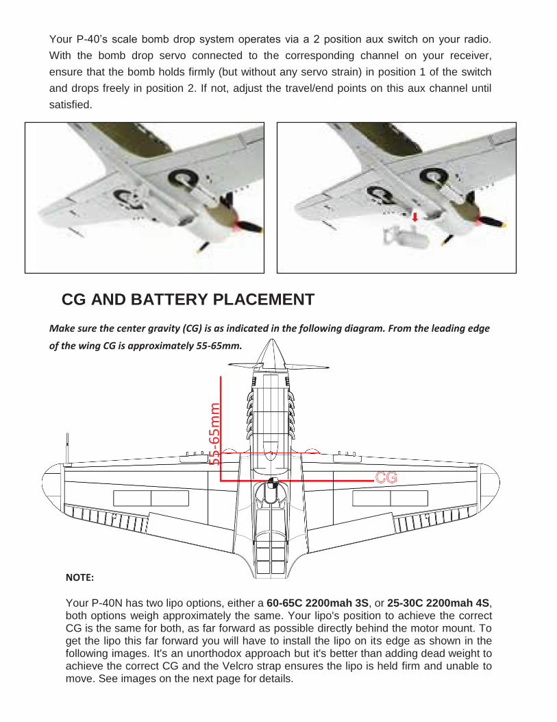
Your P-40’s scale bomb drop system operates via a 2 position aux switch on your radio.
With the bomb drop servo connected to the corresponding channel on your receiver,
ensure that the bomb holds firmly (but without any servo strain) in position 1 of the switch
and drops freely in position 2. If not, adjust the travel/end points on this aux channel until
satisfied.
CG AND BATTERY PLACEMENT
Make sure the center gravity (CG) is as indicated in the following diagram. From the leading edge
of the wing CG is approximately 55-65mm.
NOTE:
Your P-40N has two lipo options, either a 60-65C 2200mah 3S, or 25-30C 2200mah 4S, both options weigh approximately the same. Your lipo's position to achieve the correct CG is the same for both, as far forward as possible directly behind the motor mount. To get the lipo this far forward you will have to install the lipo on its edge as shown in the following images. It's an unorthodox approach but it's better than adding dead weight to achieve the correct CG and the Velcro strap ensures the lipo is held firm and unable to move. See images on the next page for details.
CG
55
-65
mm
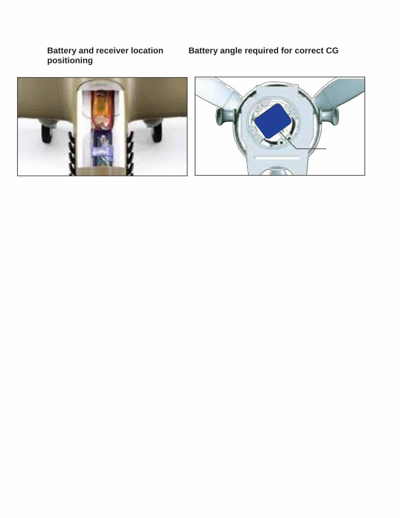
Battery
Battery and receiver location Battery angle required for correct CG positioning
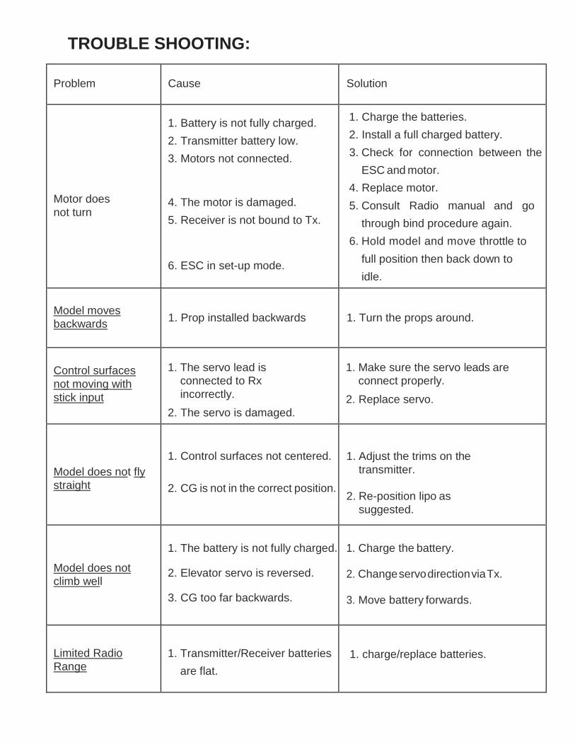
TROUBLE SHOOTING:
Problem Cause Solution
Motor does
not turn
1. Battery is not fully charged.
2. Transmitter battery low.
3. Motors not connected.
4. The motor is damaged.
5. Receiver is not bound to Tx.
6. ESC in set-up mode.
1. Charge the batteries.
2. Install a full charged battery.
3. Check for connection between the
ESC and motor.
4. Replace motor.
5. Consult Radio manual and go
through bind procedure again.
6. Hold model and move throttle to
full position then back down to
idle.
Model moves
backwards 1. Prop installed backwards 1. Turn the props around.
Control surfaces
not moving with
stick input
1. The servo lead is
connected to Rx
incorrectly.
2. The servo is damaged.
1. Make sure the servo leads are
connect properly.
2. Replace servo.
Model does not fly
straight
1. Control surfaces not centered.
2. CG is not in the correct position.
1. Adjust the trims on the
transmitter.
2. Re-position lipo as
suggested.
Model does not
climb well
1. The battery is not fully charged.
2. Elevator servo is reversed.
3. CG too far backwards.
1. Charge the battery.
2. Change servo direction via Tx.
3. Move battery forwards.
Limited Radio
Range 1. Transmitter/Receiver batteries
are flat.
1. charge/replace batteries.