Embed Size (px)
Citation preview

1
Blohm+Voss Pipe Handling Equipment
Elevator Links
Technical Documentation
Original instructions
Man
ual P
N13
4048
-D R
ev. 0
05, 2
6052
010
Blohm + Voss A Companyof ThyssenKruppMarine Systems
Repair
1.3/4” (150 sh tons/set)
2.1/4” (250 sh tons/set)
2.3/4” (350 sh tons/set)
3.1/2” (500 sh tons/set)
4.3/4” (750 sh tons/set)
5.1/2” (1000 sh tons/set)
6.1/2” (1380 sh tons/set)
2
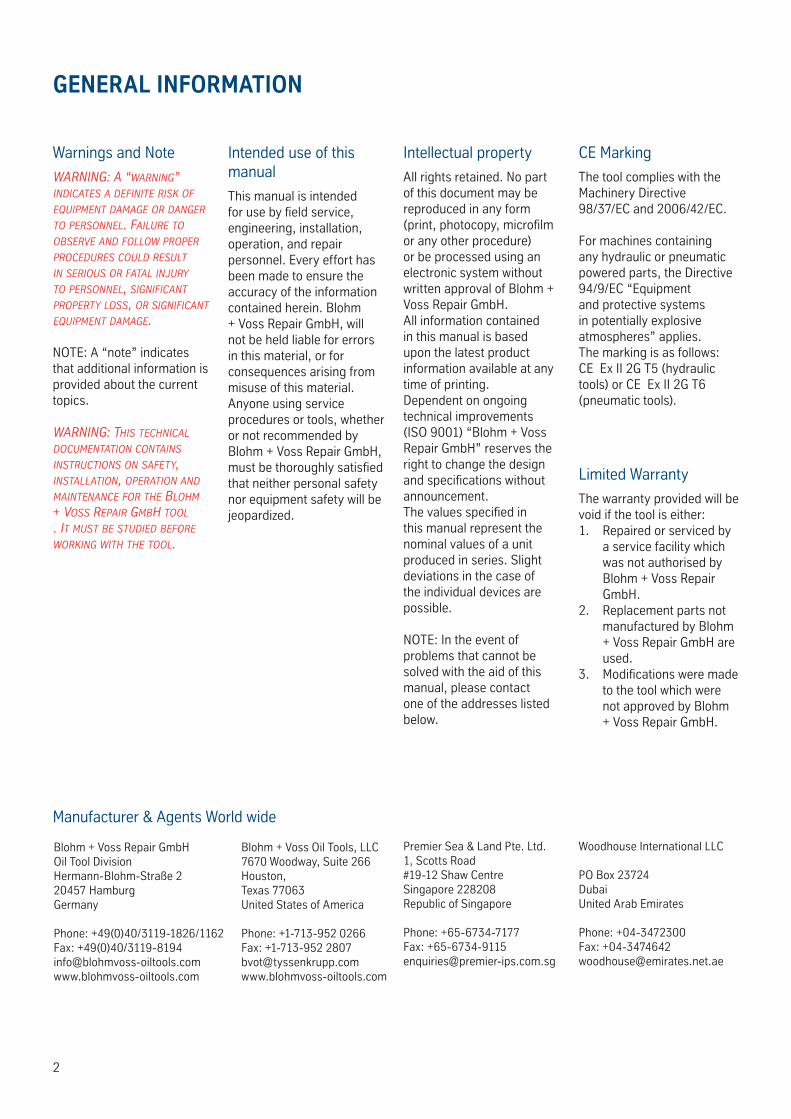
GENERAL INFORMATION
Intended use of this manual
This manual is intended for use by field service, engineering, installation, operation, and repair personnel. Every effort has been made to ensure the accuracy of the information contained herein. Blohm + Voss Repair GmbH, will not be held liable for errors in this material, or for consequences arising from misuse of this material.Anyone using service procedures or tools, whether or not recommended by Blohm + Voss Repair GmbH, must be thoroughly satisfied that neither personal safety nor equipment safety will be jeopardized.
Intellectual property
All rights retained. No part of this document may be reproduced in any form (print, photocopy, microfilm or any other procedure) or be processed using an electronic system without written approval of Blohm + Voss Repair GmbH.All information contained in this manual is based upon the latest product information available at any time of printing. Dependent on ongoing technical improvements (ISO 9001) “Blohm + Voss Repair GmbH” reserves the right to change the design and specifications without announcement. The values specified in this manual represent the nominal values of a unit produced in series. Slight deviations in the case of the individual devices are possible.
NOTE: In the event of problems that cannot be solved with the aid of this manual, please contact one of the addresses listed below.
Warnings and Note
WARNING: A “WARNING” INdIcAtes A defINIte RIsk of equIpmeNt dAmAGe oR dANGeR to peRsoNNel. fAIluRe to obseRve ANd folloW pRopeR pRoceduRes could Result IN seRIous oR fAtAl INjuRy to peRsoNNel, sIGNIfIcANt pRopeRty loss, oR sIGNIfIcANt equIpmeNt dAmAGe.
NOTE: A “note” indicates that additional information is provided about the current topics.
WARNING: thIs techNIcAl documeNtAtIoN coNtAINs INstRuctIoNs oN sAfety, INstAllAtIoN, opeRAtIoN ANd mAINteNANce foR the blohm + voss RepAIR Gmbh tool . It must be studIed befoRe WoRkING WIth the tool.
CE Marking
The tool complies with the Machinery Directive 98/37/EC and 2006/42/EC.
For machines containing any hydraulic or pneumatic powered parts, the Directive 94/9/EC “Equipment and protective systems in potentially explosive atmospheres” applies.The marking is as follows:CE Ex II 2G T5 (hydraulic tools) or CE Ex II 2G T6 (pneumatic tools).
Blohm + Voss Repair GmbHOil Tool DivisionHermann-Blohm-Straße 220457 HamburgGermany
Phone: +49(0)40/3119-1826/1162 Fax: +49(0)40/[email protected]
Premier Sea & Land Pte. Ltd.1, Scotts Road #19-12 Shaw CentreSingapore 228208Republic of Singapore
Phone: +65-6734-7177Fax: [email protected]
Manufacturer & Agents World wide
Limited Warranty
The warranty provided will be void if the tool is either:
Repaired or serviced by 1. a service facility which was not authorised by Blohm + Voss Repair GmbH.Replacement parts not 2. manufactured by Blohm + Voss Repair GmbH are used.Modifications were made 3. to the tool which were not approved by Blohm + Voss Repair GmbH.
Blohm + Voss Oil Tools, LLC7670 Woodway, Suite 266 Houston, Texas 77063United States of America
Phone: +1-713-952 0266Fax: +1-713-952 [email protected]
Woodhouse International LLC
PO Box 23724DubaiUnited Arab Emirates
Phone: +04-3472300Fax: [email protected]
3
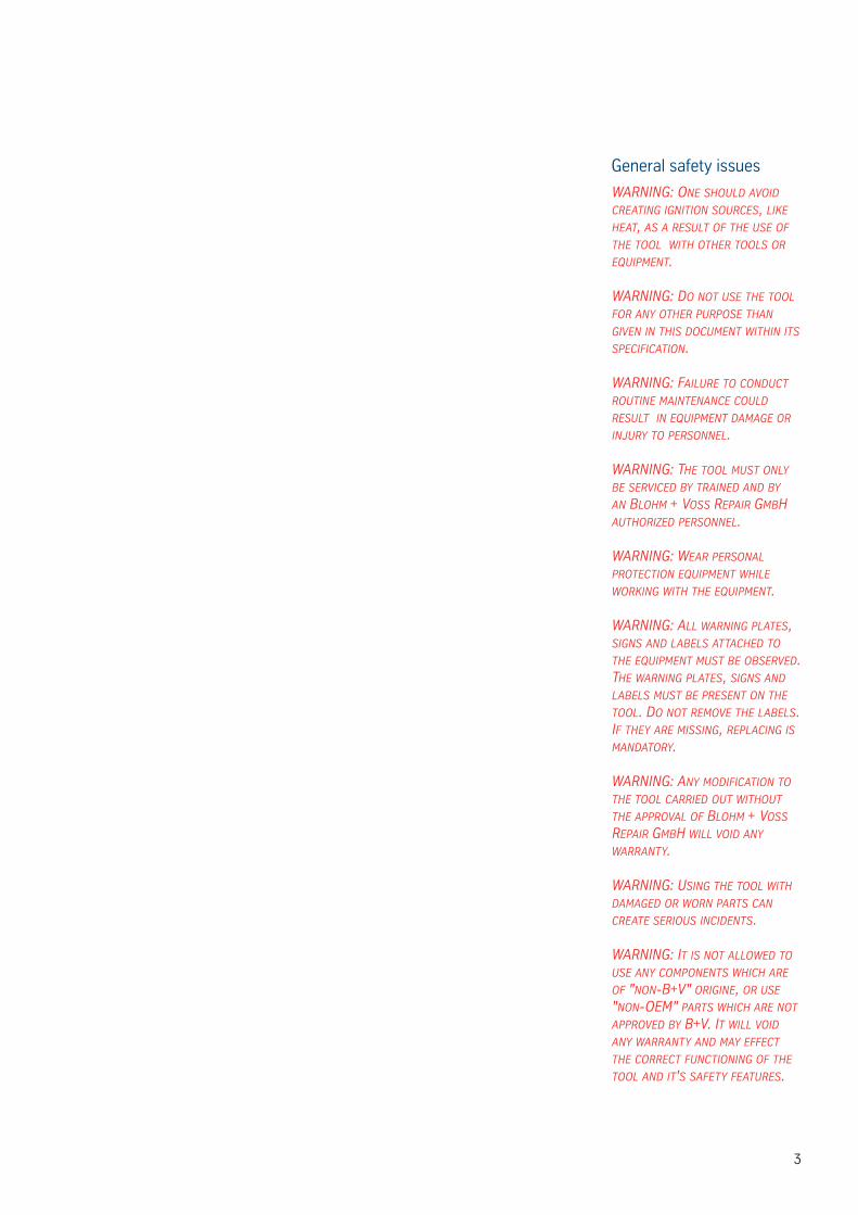
General safety issues
WARNING: oNe should AvoId cReAtING IGNItIoN souRces, lIke heAt, As A Result of the use of the tool WIth otheR tools oR equIpmeNt.
WARNING: do Not use the tool foR ANy otheR puRpose thAN GIveN IN thIs documeNt WIthIN Its specIfIcAtIoN.
WARNING: fAIluRe to coNduct RoutINe mAINteNANce could Result IN equIpmeNt dAmAGe oR INjuRy to peRsoNNel.
WARNING: the tool must oNly be seRvIced by tRAINed ANd by AN blohm + voss RepAIR Gmbh AuthoRIzed peRsoNNel.
WARNING: WeAR peRsoNAl pRotectIoN equIpmeNt WhIle WoRkING WIth the equIpmeNt.
WARNING: All WARNING plAtes, sIGNs ANd lAbels AttAched to the equIpmeNt must be obseRved. the WARNING plAtes, sIGNs ANd lAbels must be pReseNt oN the tool. do Not Remove the lAbels. If they ARe mIssING, ReplAcING Is mANdAtoRy.
WARNING: ANy modIfIcAtIoN to the tool cARRIed out WIthout the AppRovAl of blohm + voss RepAIR Gmbh WIll voId ANy WARRANty.
WARNING: usING the tool WIth dAmAGed oR WoRN pARts cAN cReAte seRIous INcIdeNts.
WARNING: It Is Not AlloWed to use ANy compoNeNts WhIch ARe of "NoN-b+v" oRIGINe, oR use "NoN-oem" pARts WhIch ARe Not AppRoved by b+v. It WIll voId ANy WARRANty ANd mAy effect the coRRect fuNctIoNING of the tool ANd It's sAfety feAtuRes.
4
We,
Blohm + Voss Repair GmbH Oil Tool Division Hermann-Blohm-Strasse 2 20457 Hamburg Phone:+49(0)40 3119-1139Fax:+49(0)40 3119-3305
declare that the product
Elevator links
which is the subject of this declaration, is in conformity with the following standard(s) or normative documents 98/37/EC: Machinery Directive DIN EN ISO 12100 : Safety of machinery, part 1 and 2 DIN EN ISO 14121-1: Safety of machinery, Risk assessment Directive 94/9/EC: Devices and protection systems for intended use in explosive areasISO 13535:2002/API 8C: Petroleum and natural gas industries-Drilling and production equipment-Hoisting equipment
EC-DECLARATION OF CONFORMITY
5
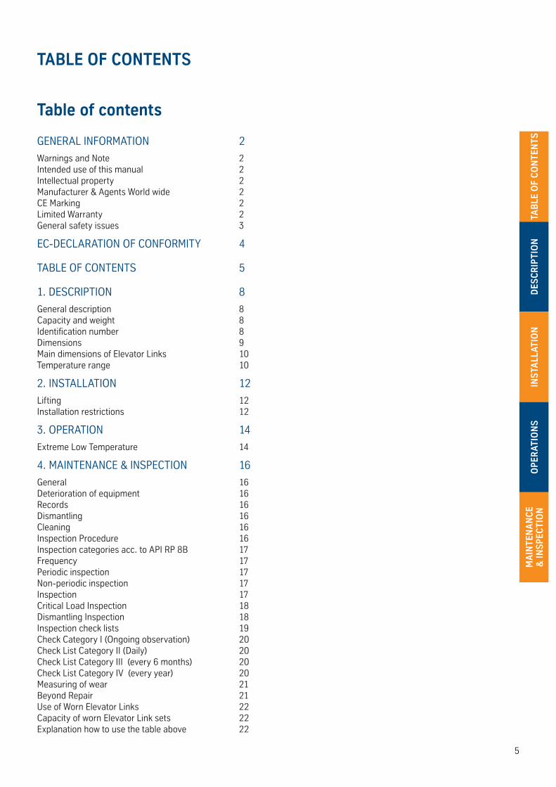
Table of contents
GENERAL INFORMATION 2
Warnings and Note 2Intended use of this manual 2Intellectual property 2Manufacturer & Agents World wide 2CE Marking 2Limited Warranty 2General safety issues 3
EC-DECLARATION OF CONFORMITY 4
TABLE OF CONTENTS 5
1. DESCRIPTION 8
General description 8Capacity and weight 8Identification number 8Dimensions 9Main dimensions of Elevator Links 10Temperature range 10
2. INSTALLATION 12
Lifting 12Installation restrictions 12
3. OPERATION 14
Extreme Low Temperature 14
4. MAINTENANCE & INSPECTION 16
General 16Deterioration of equipment 16Records 16Dismantling 16Cleaning 16Inspection Procedure 16Inspection categories acc. to API RP 8B 17Frequency 17Periodic inspection 17Non-periodic inspection 17Inspection 17Critical Load Inspection 18Dismantling Inspection 18Inspection check lists 19Check Category I (Ongoing observation) 20Check List Category II (Daily) 20Check List Category III (every 6 months) 20Check List Category IV (every year) 20Measuring of wear 21Beyond Repair 21Use of Worn Elevator Links 22Capacity of worn Elevator Link sets 22Explanation how to use the table above 22
TABLE OF CONTENTS
TAB
LE O
F C
ON
TEN
TSD
ESC
RIP
TIO
NIN
STA
LLAT
ION
OP
ERAT
ION
SM
AIN
TEN
AN
CE
& IN
SP
ECTI
ON
6
TAB
LE OF C
ON
TENTS
DES
CR
IPTIO
NIN
STA
LLATION
OP
ERATIO
NS
MA
INTEN
AN
CE
& IN
SP
ECTIO
N

7
DES
CR
IPTI
ON
DESCRIPTION

8
DES
CR
IPTIO
N
1. DESCRIPTION
General description
Elevator links are designed to hang elevators. They are to be used for their designated purpose only. The links are available in 150, 250, 350, 500, 750, 1000 and 1380 mton ratings.
Capacity and weight
Elevator Link PN Size Rated capacity (ton) Weight (kg / lbs)
134048-Y 1.3/4" x 48" 150 154 / 340
12" increases 150 18 / 40
134144-Y 1.3/4" x 144" 150 298 / 655
214048-Y 2.1/4" x 48" 250 180 / 396
12" increases 250 23 / 51
214180-Y 2.1/4" x 180" 250 433 / 953
214240-Y 2.1/4" x 240" (20 ft) 250 544 / 1197
214360-Y 2.1/4" x 360" (30 ft) 250 780 / 1720
214480-Y 2.1/4" x 480" (40 ft) 250 1000 / 2205
234048-Y 2.3/4" x 48" 350 270 / 594
12" increases 350 29 / 64
234216-Y 2.3/4" x 216" 350 734 / 1615
234240-Y 2.3/4" x 240" (25 ft) 350 790 / 1742
60 " (5 ft) increases 350 145 / 320
234600-Y 2.3/4" x 600" (50 ft) 350 1766 / 3894
312072-Y 3.1/2" x 72" 500 478 / 1050
12" increases 500 52 / 115
312216-Y 3.1/2" x 216" 500 1102 / 2425
312240-Y 3.1/2" x 240" (20 ft) 500 1200 / 2640
60" (5 ft) increases 500 260 / 575
312660-Y 3.1/2" x 660" (55 ft) 500 3236 / 7135
434108-Y 4.3/4" x 108" 750 1030 / 2265
12" increases 750 76 / 170
434216-Y 4.3/4" x 216" 750 1714 / 3770
434240-Y 4.3/4" x 240" (20 ft) 750 1862 / 4105
60" (5 ft) increases 750 380 / 838
434660-Y 4.3/4" x 660" (55 ft) 750 4514 / 9552
512180-Y 5.1/2" x 180" 1000 2630 / 5786
612180-Y 6.1/2" x 180" 1380 3580/7876
For the 1000 and 1380 ton elevator links other sizes can be obtained upon request.
Identification number
Every Elevator link should have an idenification number. This number is stamped near an eye.
9
DES
CR
IPTI
ON
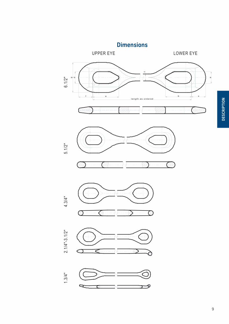
Dimensions
dg
f e
c
a
1.3/
4"2.
1/4"
-3.1
/2"
4.3/
4"5.
1/2"
6.1/
2"
UPPER EYE LOWER EYE
b xlength as ordered
10
DES
CR
IPTIO
N
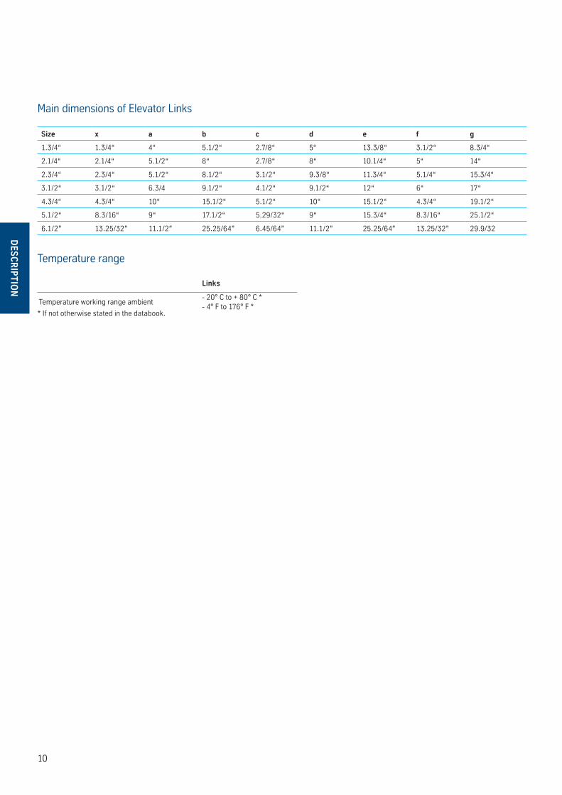
Main dimensions of Elevator Links
Size x a b c d e f g
1.3/4“ 1.3/4“ 4“ 5.1/2“ 2.7/8“ 5“ 13.3/8“ 3.1/2“ 8.3/4“
2.1/4“ 2.1/4“ 5.1/2“ 8“ 2.7/8“ 8“ 10.1/4“ 5“ 14“
2.3/4“ 2.3/4“ 5.1/2“ 8.1/2“ 3.1/2“ 9.3/8“ 11.3/4“ 5.1/4“ 15.3/4“
3.1/2“ 3.1/2“ 6.3/4 9.1/2“ 4.1/2“ 9.1/2“ 12“ 6“ 17“
4.3/4“ 4.3/4“ 10“ 15.1/2“ 5.1/2“ 10“ 15.1/2“ 4.3/4“ 19.1/2“
5.1/2“ 8.3/16“ 9“ 17.1/2“ 5.29/32“ 9“ 15.3/4“ 8.3/16“ 25.1/2“
6.1/2” 13.25/32” 11.1/2” 25.25/64” 6.45/64” 11.1/2” 25.25/64” 13.25/32” 29.9/32
Links
Temperature working range ambient- 20° C to + 80° C *- 4° F to 176° F *
* If not otherwise stated in the databook.
Temperature range
11
INS
TALL
ATIO
N
INSTALLATION
12
INS
TALLATIO
N
2. INSTALLATION
Lifting
Lift the elevator links by means of a crane. The lifting procedures should be carefully observed!
Installation restrictions
The elevator link is to be used as a connecting element beween hook and elevator. It must never by used for any other purpose. Never exceed the designated load.
13
OP
ERAT
ION
S
OPERATIONS
14
OP
ERATIO
NS
3. OPERATION
Extreme Low Temperature
Ratings have been established at a temperature of minus 20°C. The effect of low temperature on steel must be recognized although no changes in design safety factors have been provided. When operating at low temperatures, caution must be exercised to take into account the lower impact capabilities of many steels which are typically employed. The risk of failure may be reduced by a critical load inspection.
15
MA
INTE
NA
NC
E &
INS
PEC
TIO
N
MAINTENANCE & INSPECTION

16
MA
INTEN
AN
CE
& IN
SP
ECTIO
N
4. MAINTENANCE & INSPECTION
General
If cracks, excessive wear etc. is recognised, contact Blohm + Voss Repair GmbH or an authorised service company.Weldings of the castings should be done only by Blohm + Voss Repair GmbH or an authorised service company in according to Blohm + Voss welding procedure.
Deterioration of equipment
Normal wear in course of use will eventually reduce the capability of the elevator links. The existence or cracks, or the appearance of defects, can indicate severe deterioration, even impending failure, and prompt attention is required either to remove the elevator link from service immediately, or to undertake appropriate repair as required.
Records
Inspection procedure are listed in this recommended practice and generalized sketches of the elevator links showing points to be inspected are to be provided. Written records should be maintained which accurately record the inspection and maintenance history of each elevator link. Records should include the date, personnel involved, and results of each inspection or maintenance procedure performed.
WARNING: NeveR Weld oN elevAtoR lINks!
Dismantling
The elevator links should be dismantled from the rig and inspected in a usitably equipped facility for excessive wear, cracks, flaws or deformation. Corrections should be made in accordance with recommendations which can be obtained from Blohm + Voss.
Cleaning
Before inspection, all foreign material such as dirt, paint, grease, oil, scale, etc. should be removed from the areas to be inspected by a suitable method.
Inspection Procedure
The inspection should be made by trained, competent personnel.

17
MA
INTE
NA
NC
E &
INS
PEC
TIO
N
Category IThis category involves observing the equipment during operation for indications of inadequate performance.When in use, equipment shall be visually inspected on a daily basis for cracks, loose fits or connections, elongation of part, and other signs of wear, corrosion or overloading. Any parts found to show cracks, excessive wear, etc., shall be removed from service for further examination.The equipment shall be visually inspected by a person knowledgeable in that equipment and its function.
Category IIThis is Category I inspection plus further inspection for corrosion, deformation, loose or missing components, deterioration, proper lubrication, visible external cracks, and adjustment. Category II may involve some disassembly to access specific components and to identify wear that exceeds the allowable tolerances.
Category IIIThis is Category II inspection plus further inspection, which should include NDT of critical areas and may involve some disassembly to access specific components and to identify wear that exceeds the allowable tolerances.Prior to inspection, all foreign material such as dirt, paint, grease, oil, scale, etc. shall be removed from the concerned parts by a suitable method (e.g. paint-stripping, steam-cleaning, grit-blasting).
Category IVThis is Category III inspection plus further inspection for which the equipment is disassembled to the extent necessary to conduct NDT of all primary-load-carrying components.
Equipment shall be:disassembled in a suitable-• equipped facility to the extent necessary to permit full inspection of all primary-load-carrying components and other components that are critical to the equipment.inspected for excessive wear, • cracks, flaws and deformation.
Procedure:Corrections shall be made • in accordance with the manufacturer’s recommendations.Prior to inspection, all foreign • material such as dirt, paint, grease, oil, scale, etc. shall be removed from the concerned parts by a suitable method (e.g. paint-stripping, steam-cleaning, grit-blasting)
Frequency
Periodic inspection
The recommended schedule for inspection of all kind of
Elevators:• Daily: I+II6 Monthly: III1 Year: IV
Spiders:• Daily: IWeekly: II6 Monthly: III1 Year: IV
Power Slips:• Daily: IWeekly: II6 Monthly: III2 Year: IV
The recommended frequencies apply for equipment in use during the specified period.
The inspection frequencies are only recommendations. The schedule of inspection heavily depends on the following factors:
environment• load cycles• regulatory requirements• operating time• testing• repairs• re manufacture•
Non-periodic inspection
A complete, on-job, shut-down inspection equivalent to the periodical Category III or Category IV should be made before (if anticipated) and after critical jobs (e.g., running heavy casing / drill strings, jarring, pulling on stuck pipes and/or operating at extreme low temperatures) <-20° C (<-4° F).
Inspection
A thorough inspection should be carried out periodically (every 3 months) or as special circumstances may require. Before starting an inspection disconnect hydraulic/pneumatic system and remove all foreign materials (dirt, paint, grease Oil, scale, etc.) from surface by a suitable method. After a field inspection, it is advisable to record the extent of testing and testing results. Conduct the periodic or critical load inspection in the field by the crew with the supervisor. If cracks, excessive wear etc. is recognized, contact Blohm + Voss Repair GmbH or an authorized service company.
Inspection categories acc. to API RP 8B
18
MA
INTEN
AN
CE
& IN
SP
ECTIO
N
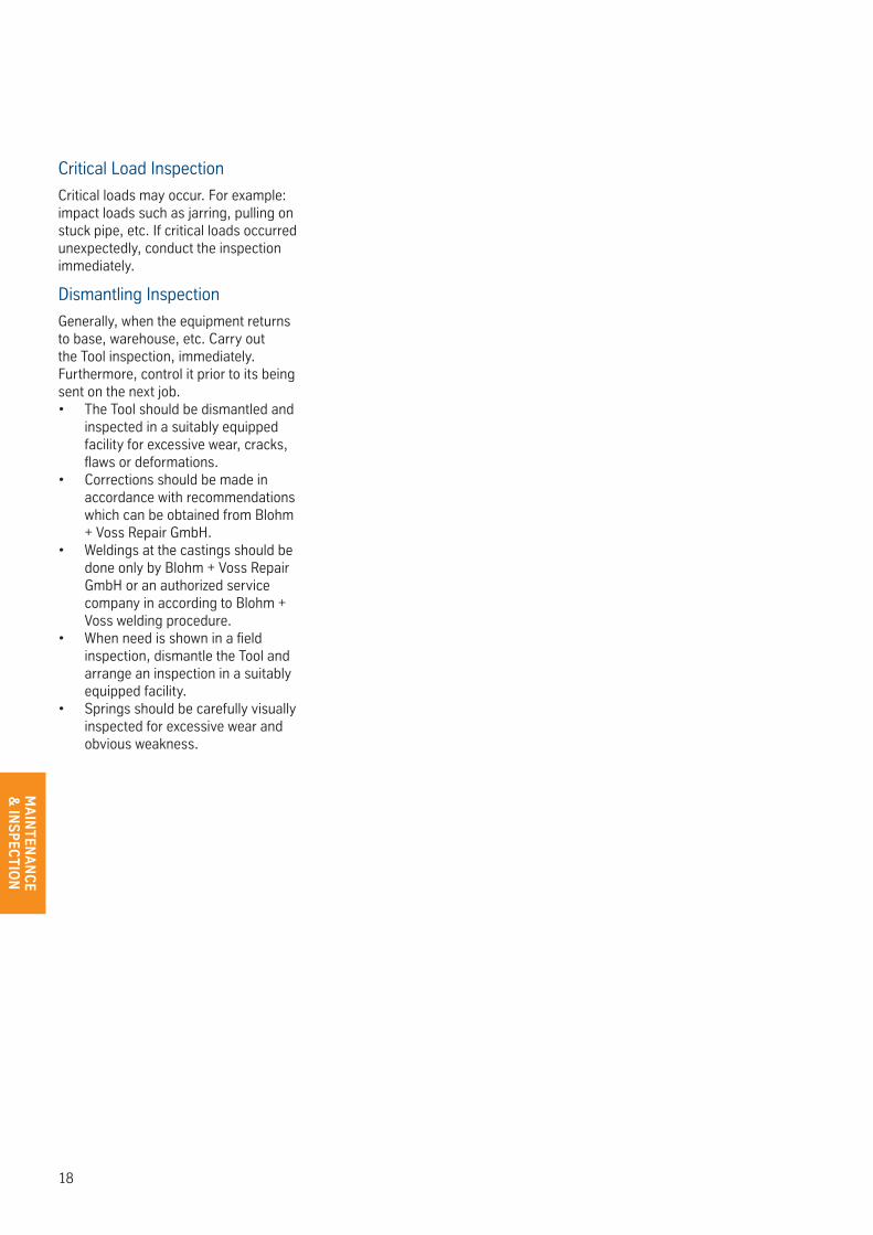
Critical Load Inspection
Critical loads may occur. For example: impact loads such as jarring, pulling on stuck pipe, etc. If critical loads occurred unexpectedly, conduct the inspection immediately.
Dismantling Inspection
Generally, when the equipment returns to base, warehouse, etc. Carry out the Tool inspection, immediately. Furthermore, control it prior to its being sent on the next job.
The Tool should be dismantled and • inspected in a suitably equipped facility for excessive wear, cracks, flaws or deformations.Corrections should be made in • accordance with recommendations which can be obtained from Blohm + Voss Repair GmbH.Weldings at the castings should be • done only by Blohm + Voss Repair GmbH or an authorized service company in according to Blohm + Voss welding procedure.When need is shown in a field • inspection, dismantle the Tool and arrange an inspection in a suitably equipped facility.Springs should be carefully visually • inspected for excessive wear and obvious weakness.

19
MA
INTE
NA
NC
E &
INS
PEC
TIO
N
Inspection check lists
CHECK LIST FRONT PAGE
TYPE OF EQUIPMENT
SERIAL NUMBER
PART NUMBER
SUPERVISOR
DATE OF INSPECTION
INSPECTION CATEGORY
PLACE OF INSPECTION
20
MA
INTEN
AN
CE
& IN
SP
ECTIO
N
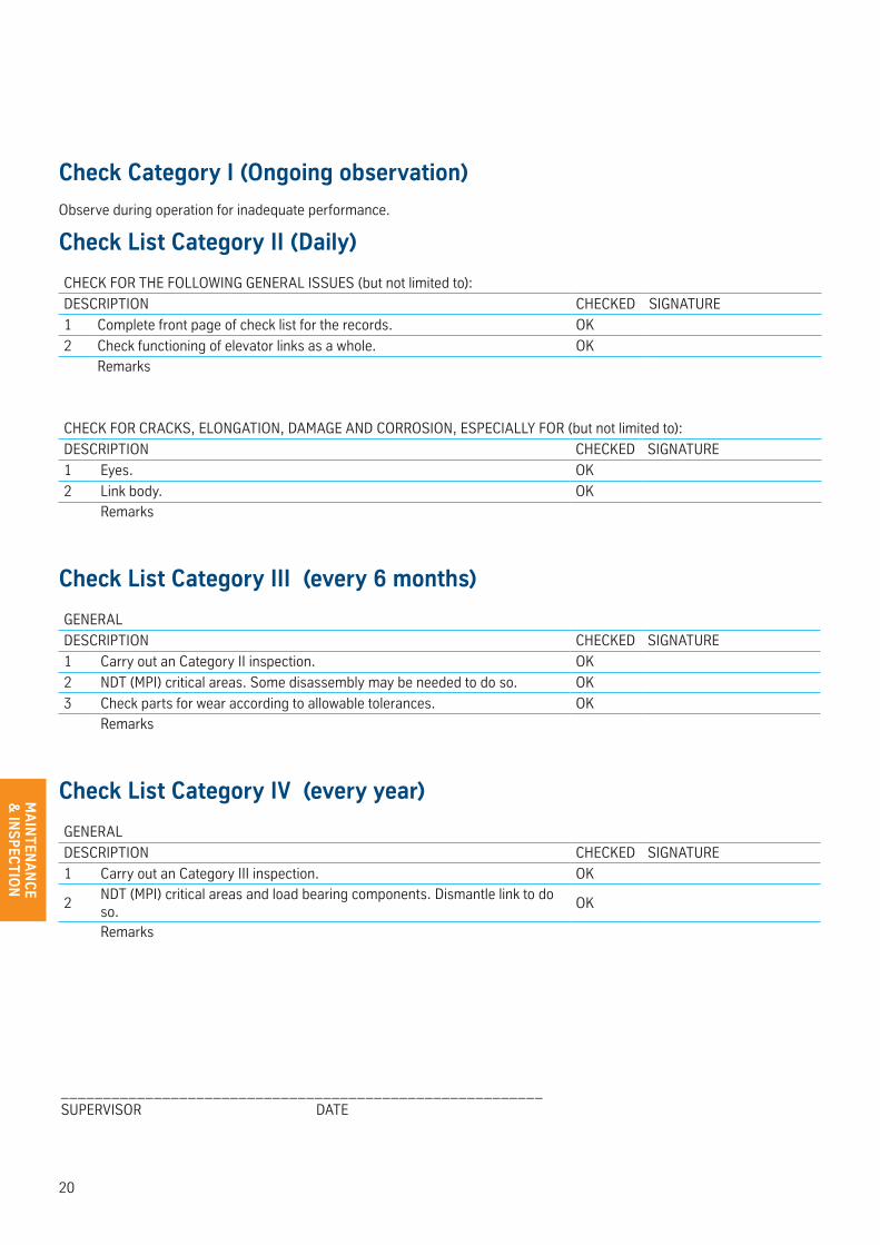
Check Category I (Ongoing observation)
Observe during operation for inadequate performance.
Check List Category II (Daily)
CHECK FOR THE FOLLOWING GENERAL ISSUES (but not limited to):
DESCRIPTION CHECKED SIGNATURE
1 Complete front page of check list for the records. OK
2 Check functioning of elevator links as a whole. OKRemarks
CHECK FOR CRACKS, ELONGATION, DAMAGE AND CORROSION, ESPECIALLY FOR (but not limited to):
DESCRIPTION CHECKED SIGNATURE
1 Eyes. OK
2 Link body. OKRemarks
Check List Category III (every 6 months)
GENERAL
DESCRIPTION CHECKED SIGNATURE
1 Carry out an Category II inspection. OK
2 NDT (MPI) critical areas. Some disassembly may be needed to do so. OK
3 Check parts for wear according to allowable tolerances. OKRemarks
Check List Category IV (every year)
GENERAL
DESCRIPTION CHECKED SIGNATURE
1 Carry out an Category III inspection. OK
2NDT (MPI) critical areas and load bearing components. Dismantle link to do so.
OK
Remarks
_________________________________________________________SUPERVISOR DATE
21
MA
INTE
NA
NC
E &
INS
PEC
TIO
N
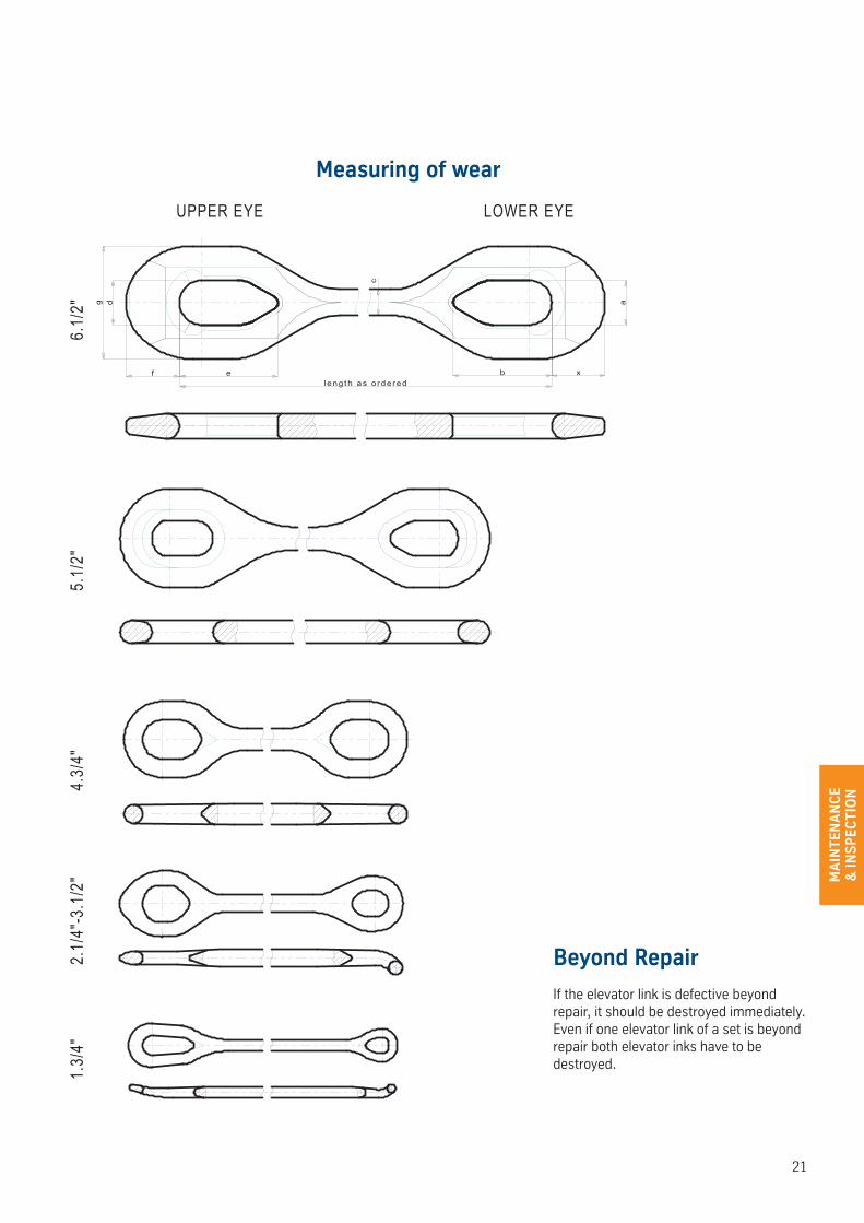
Beyond Repair
If the elevator link is defective beyond repair, it should be destroyed immediately. Even if one elevator link of a set is beyond repair both elevator inks have to be destroyed.
dg
f ec
a
1.3/
4"2.
1/4"
-3.1
/2"
4.3/
4"5.
1/2"
6.1/
2"
UPPER EYE LOWER EYE
b xlength as ordered
Measuring of wear
22
MA
INTEN
AN
CE
& IN
SP
ECTIO
N
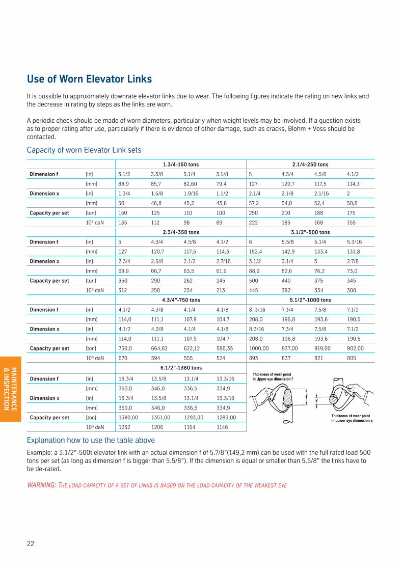
Use of Worn Elevator Links
It is possible to approximately downrate elevator links due to wear. The following figures indicate the rating on new links and the decrease in rating by steps as the links are worn.
A periodic check should be made of worn diameters, particularly when weight levels may be involved. If a question exists as to proper rating after use, particularly if there is evidence of other damage, such as cracks, Blohm + Voss should be contacted.
Capacity of worn Elevator Link sets
1.3/4-150 tons 2.1/4-250 tons
Dimension f [in] 3.1/2 3.3/8 3.1/4 3.1/8 5 4.3/4 4.5/8 4.1/2
[mm] 88,9 85,7 82,60 79,4 127 120,7 117,5 114,3
Dimension x [in] 1.3/4 1.5/8 1.9/16 1.1/2 2.1/4 2.1/8 2.1/16 2
[mm] 50 46,8 45,2 43,6 57,2 54,0 52,4 50,8
Capacity per set [ton] 150 125 110 100 250 210 188 175
10³ daN 135 112 98 89 222 185 168 155
2.3/4-350 tons 3.1/2”-500 tons
Dimension f [in] 5 4.3/4 4.5/8 4.1/2 6 5.5/8 5.1/4 5.3/16
[mm] 127 120,7 117,5 114,3 152,4 142,9 133,4 131,8
Dimension x [in] 2.3/4 2.5/8 2.1/2 2.7/16 3.1/2 3.1/4 3 2.7/8
[mm] 69,9 66,7 63,5 61,9 88,9 82,6 76,2 73,0
Capacity per set [ton] 350 290 262 245 500 440 375 345
10³ daN 312 258 234 213 445 392 334 308
4.3/4”-750 tons 5.1/2”-1000 tons
Dimension f [in] 4.1/2 4.3/8 4.1/4 4.1/8 8. 3/16 7.3/4 7.5/8 7.1/2
[mm] 114,0 111,1 107,9 104,7 208,0 196,8 193,6 190,5
Dimension x [in] 4.1/2 4.3/8 4.1/4 4.1/8 8.3/16 7.3/4 7.5/8 7.1/2
[mm] 114,0 111,1 107,9 104,7 208,0 196,8 193,6 190,5
Capacity per set [ton] 750,0 664,82 622,12 586,35 1000,00 937,00 919,00 902,00
10³ daN 670 594 555 524 893 837 821 805
6.1/2”-1380 tons
Dimension f [in] 13.3/4 13.5/8 13.1/4 13.3/16
[mm] 350,0 346,0 336,5 334,9
Dimension x [in] 13.3/4 13.5/8 13.1/4 13.3/16
[mm] 350,0 346,0 336,5 334,9
Capacity per set [ton] 1380,00 1351,00 1293,00 1283,00
10³ daN 1232 1206 1154 1146
Explanation how to use the table above
Example: a 3.1/2”-500t elevator link with an actual dimension f of 5.7/8”(149,2 mm) can be used with the full rated load 500 tons per set (as long as dimension f is bigger than 5.5/8”). If the dimension is equal or smaller than 5.5/8” the links have to be de-rated.
WARNING: the loAd cApAcIty of A set of lINks Is bAsed oN the loAd cApAcIty of the WeAkest eye