Embed Size (px)
Citation preview
Bluetoothreg Low Energy Measurements Using RampSregCBTgo Additional Tests
Application Note
Products
| RampSCBT
| RampSCBT32
| RampSCBT-K57
| RampSCBTgo
| RampSSMF
| RampSSMW200A
| RampSSMU200A
| RampSSMJ100A
| RampSSMBV100A
| RampSSMB
| RampSSMR
Nearly all tests in accordance with the
Bluetooth low energy test specification V40
[1] can be performed using the RampSregCBT
alone Some tests additionally call for signal
generators to provide interference signals
This application note describes the tests
performed with additional equipment and
presents straightforward solutions based on
the RampSregCBTgo software
Please note that Basic Rate and EDR
Measurements are covered in the application
note 1MA106
App
licat
ion
Not
e
Ber
nhar
d S
chul
z
July
201
3 -
1MA
200_
3e
Table of Contents
1MA200_3e Rohde amp Schwarz Bluetooth LE Measurements 2
Table of Contents
1 Introduction 3
2 General 3
21 Bluetooth Low Energy (BLE) Parameter 3
22 CBTgo 5
221 PC Hardware and Software Requirements 5
222 Operation of CBTgo 6
2221 Preparing for Operation 6
2222 Required Standard CBTgo Modules 9
3 Stipulated Measurements 10
31 CI and Receiver Selectivity Performance (RCV-LECA03C) 10
32 Blocking Performance (RCV-LECA04C) 15
33 Intermodulation Performance (RCV-LECA05C) 20
4 Appendix 25
41 References 25
42 Additional Information 25
43 Ordering Information 26
The following abbreviations are used in this application note for Rohde amp Schwarz test equipment
The RampSregCBTCBT32 Bluetooth
reg1) tester is referred to as the CBT
The RampSregCBTgo software is referred to as CBTgo
The RampSregSMF microwave signal generator is referred to as the SMF
The RampSregSMB100A microwave signal generator is referred to as the SMB
The RampSregSMW200A vector signal generator is referred to as the SMW
The RampSregSMJ100A vector signal generator is referred to as the SMJ
The RampSregSMATE200A vector signal generator is referred to as the SMATE
The RampSregSMU200A vector signal generator is referred to as the SMU
The RampSregSMBV100A vector signal generator is referred to as the SMBV
The RampSregSMR microwave signal generator is referred to as the SMR
1)
The Bluetoothreg word mark and logos are registered trademarks owned by Bluetooth
SIG Inc and any use of such marks by Rohde amp Schwarz is under license Other trademarks and trade names are those of their respective owners
Introduction
Bluetooth Low Energy (BLE) Parameter
1MA200_3e Rohde amp Schwarz Bluetooth LE Measurements 3
1 Introduction In version 40 of the Bluetooth specification [1] the low energy (LE) function was
introduced This function addresses devices that although they have to transmit only
small data volumes must feature very low energy consumption but very long battery
runtimes They are known as button-cell devices such as wristwatches sensors for
sport and personal health monitoring as well as remote control devices
The air interface they use (low energy RF ndash LE RF) is similar to the air interface of the
Bluetooth basic rate (V11) However some parameters such as channel spacing
modulation index and packet structure are different In addition pure transmitter or
pure receiver devices are also possible
Rohde amp Schwarz offers the established CBT Bluetooth tester family for RF tests The
tester is available in two versions (CBT CBT32) and performs qualified RF
measurements in line with Bluetooth SIG at an extremely high speed Equipped with
the CBT-K57 software option it also supports the low energy tests
In addition Rohde amp Schwarz provides the free-of-charge CBTgo PC software for
controlling the CBT Using CBTgo you can conveniently create any desired test
sequences by configuring and combining selectable test modules CBTgo offers a
number of sample sequences eg for automatically performing the various Bluetooth
RF test cases
Some tests require besides the CBT additional instruments such as signal
generators This application note describes how to perform these tests using CBTgo
2 General
21 Bluetooth Low Energy (BLE) Parameter
On the air interface BLE is similar to the basic rate and therefore offers data rates of
1 Msymbols using GFSK modulation Unlike the basic rate it uses a modulation index
of 05 which results in a frequency deviation of 250 kHz In addition in the ISM band
only 40 channels with a spacing of 2 MHz are defined The level range is the same as
that of the normal Bluetooth to save energy the usual transmit levels are at 0 dBm
A special test packet has been defined for the RF tests The length of the payload (and
therefore the length of the test packet) may vary depending on the test With the
maximum payload length of 37 byte the complete packet has a length of 376 bit and
thus a duration of 376 μs
General
Bluetooth Low Energy (BLE) Parameter
1MA200_3e Rohde amp Schwarz Bluetooth LE Measurements 4
Fig 1 Overview of the LE test packet [1] The length of the PDU payload may vary depending on the
test
The individual tests are defined in accordance with [1] (Table 1 and Table 2) All tests
can be performed using the CBT and CBTgo This application note discusses the
receiver tests marked in green NOC stands for normal operating conditions and EOC
for extreme operating conditions
Transmitter tests (TRM-LE)
Test Designation Section
Output power at NOC TRMCA-01-C 621
Output power at EOC TRMCA-02-C 622
In-band emissions at NOC TRMCA-03-C 623
In-band emissions at EOC TRMCA-04-C 624
Modulation characteristics TRMCA-05-C 625
Carrier frequency offset and drift at NOC TRMCA-06-C 626
Carrier frequency offset and drift at EOC TRMCA-07-C 627
Table 1 Overview of LE transmitter tests
Receiver tests (RCV-LE)
Test Designation Section
Receiver sensitivity at NOC RCVCA-01-C 631
Receiver sensitivity at EOC RCVCA-02-C 632
CI and receiver selectivity performance RCVCA-03-C 633
Blocking performance RCVCA-04-C 634
Intermodulation performance RCVCA-05-C 635
Maximum input signal level RCVCA-06-C 636
PER report integrity RCVCA-07-C 637
Table 2 Overview of LE receiver tests
General
CBTgo
1MA200_3e Rohde amp Schwarz Bluetooth LE Measurements 5
Direct test mode
Low energy tests are performed in a direct test mode an RF connection is not made
In the test the DUT is put into the direct test mode via a local serial interface Test
commands such as the frequency to be tested or reading out the properly received
packets during RX tests run via an external interface The CBT can send these
commands via RS-232-C (COM port)
22 CBTgo
CBTgo is a PC software application for remote control of the CBT The software can be
downloaded free-of-charge from the Rohde amp Schwarz website Using CBTgo you can
conveniently create any desired test sequences by configuring and combining
selectable test modules This requires no knowledge of remote programming The
software generates measurement reports at the press of a button Reports can be
stored in various formats
CBTgo offers a number of sample sequences eg for automatically performing the
various Bluetooth RF test cases Reports of remote commands can also be output
stating the times of the individual steps and such reports can be copied to the
Windows clipboard for further use The software allows a large number of graphical
elements to be integrated into the measurement report and is thus a valuable tool in
RampD and product verification
221 PC Hardware and Software Requirements
Hardware requirements
CPU at least 300 MHz
RAM at least 64 Mbyte
Monitor SVGA with 800 x 600 pixels or higher
Hard disk 50 Mbyte available space
Peripherals National Instruments GPIB-bus or RS-232-C interface mouse
Software requirements
Windows 98ME2000XP7
CBTgo V220 with V220 Bluetooth modules or later
General
CBTgo
1MA200_3e Rohde amp Schwarz Bluetooth LE Measurements 6
222 Operation of CBTgo
Please refer to the CBTgo manual [2] for information on how to connect the computer with the CBT as well as how to install start and operate CBTgo
2221 Preparing for Operation
Setting the GPIB parameters in CBTgo
The GPIB parameters of the CBT can be set via CONFIGURATION|REMOTE PORT CBTgo uses auxiliary channels in order to communicate with additional devices To configure an additional device open the Configuration menu (Fig 2) and select an Auxiliary GPIB Port A window with further parameters will open (Fig 3)
Fig 2 Configuration menu of CBTgo Set the auxiliary port and the BT Low Energy device mode
General
CBTgo
1MA200_3e Rohde amp Schwarz Bluetooth LE Measurements 7
Fig 3 Auxiliary GPIB Port x
The device name entered under Auxiliary GPIB Port x must be identical to the name entered in the Bluetooth modules for the individual tests The usual GPIB parameters can be set Note that Enable Port must be enabled
Setting the reference frequency in CBTgo
Via the Basic Initializing module the CBT can be synchronized with other equipment
using a 10 MHz clock signal For this purpose enable External 10 MHz Reference
(Fig 6) and connect a BNC cable between the REF OUT output of a
generatoranalyzer and the REF IN socket of the CBT
Setting the LE device mode in CBTgo
In low energy mode the individual Bluetooth products are not controlled via signaling
but rather must be controlled directly via an interface To make the settings for this
select BT Low Energy Device in the CBTgo Configuration menu (see Fig 4 and Fig 5)
General
CBTgo
1MA200_3e Rohde amp Schwarz Bluetooth LE Measurements 8
Fig 4 Setting the LE device mode
Fig 5 Configuration CBT LE DUT interface
Measuring the attenuation values
To obtain correct results the attenuation between the CBT and the DUT must be measured and entered into the BT Call Setup module Likewise the attenuation between the DUT and the signal generator(s) andor the spectrum analyzer must be measured and entered into the appropriate module(s) Rohde amp Schwarz also offers the free-of-charge FreRes software which allows you to record the frequency response It is available under httpwwwrohde-schwarzcomappnote1MA09
General
CBTgo
1MA200_3e Rohde amp Schwarz Bluetooth LE Measurements 9
2222 Required Standard CBTgo Modules
For proper operation all new modules presented here require other CBTgo modules
For these basic modules detailed descriptions already exist (see [3]) therefore only
the main settings will be described in this document
Each test sequence requires the Basic Initializing and the BT Low Energy
Connection Setup modules
Basic Initializing must be the first module of every sequence Please enable the
Bluetooth Low Energy function group here
Fig 6 Basic Initializing module
The Bluetooth LE Connection Setup module is required at the start of each Bluetooth
low energy test sequence (after Basic Initializing) The main parameters for setting up
a connection to a Bluetooth low energy device are set in this module
Fig 7 Bluetooth low energy connection setup
Besides the attenuation parameters you can either set the Autoranging mode or enter
a maximum level manually
Stipulated Measurements
CI and Receiver Selectivity Performance (RCV-LECA03C)
1MA200_3e Rohde amp Schwarz Bluetooth LE Measurements 10
3 Stipulated Measurements
31 CI and Receiver Selectivity Performance
(RCV-LECA03C)
This test verifies the receiver performance of the DUT in presence of a Bluetooth
co-adjacent channel interferer within the Bluetooth band The result is obtained by
means of a packet error rate (PER) measurement
The wanted signal is transmitted on a single channel in non-hopping mode A
Bluetooth interferer is likewise generated on a single channel coupled in and the PER
is determined In the next step the Bluetooth interferer is generated on all channels
one after the other and the PER is measured for each interferer channel The
complete test sequence is repeated twice ie the PER measurement is performed with
the wanted signal on three channels in total (Fig 8)
Fig 8 CI performance For the three individual channels the packet error rate in the presence of a
Bluetooth interferer inside the Bluetooth band is measured The measurement is repeated after
shifting the interferer by 1 MHz
The Bluetooth test specification defines the following settings
DUT in direct RX mode
Hopping off (RX on single channel)
Three channels (0 19 39)
Test packets with 37 octet PRBS9 payload
Interferer GFSK (modulation index 05) with PRBS15 on all Bluetooth channels in
consecutive order
1500 packets
Wanted input level at EUT 67 dBm
For levels see Table 3
Stipulated Measurements
CI and Receiver Selectivity Performance (RCV-LECA03C)
1MA200_3e Rohde amp Schwarz Bluetooth LE Measurements 11
CI level settings
Interference signal frequency Interferer
level (abs)
CI level Wanted
signal (abs)
Co-channel
(f RX = f Interference )
ndash88 dBm 21 dB ndash67 dBm
Adjacent channel
(f Interference = f RX plusmn 1 MHz )
ndash82 dBm 15 dB ndash67 dBm
Adjacent channel
(f Interference = f RX plusmn 2 MHz )
ndash50 dBm ndash17 dB ndash67 dBm
Adjacent channel
(f Interference = f RX plusmn (3 + n) MHz )
ndash40 dBm ndash27 dB ndash67 dBm
Image frequency
(f Interference = f Image )
ndash58 dBm ndash9 dB ndash67 dBm
Adjacent channel to image frequency
(f Interference = f Image plusmn 1 MHz )
ndash52 dBm ndash15 dB ndash67 dBm
Table 3 CI and receiver selectivity test parameter settings [1]
Results
For all measurements the PER must be better than 308 for a minimum of 1500
packets
For each of the three wanted channels the PER may exceed 308 for five
interferer frequencies spaced ge 2 MHz from the carrier and spaced ge 1 MHz from
the image frequency
For the interferer frequencies (max five) at which the PER limit is exceeded the
PER is measured in a second test run with a relaxed CI of 17 dB The PER limit
is again 308
Test setup
Fig 9 shows a typical test setup The CBT and the DUT are connected to each other
by a combiner via which the interference signal from a Bluetooth generator is coupled
in If the DUT transmits at high power levels an attenuator may be inserted to protect
the generator
Stipulated Measurements
CI and Receiver Selectivity Performance (RCV-LECA03C)
1MA200_3e Rohde amp Schwarz Bluetooth LE Measurements 12
Fig 9 Test setup for CI performance measurement
Measuring equipment and accessories
CBT tester SMx (SMU SMJ SMATE SMBV) signal generator
Resistive combiner up to 25 GHz (eg Weinschel 1515 1)
Attenuator up to 25 GHz (eg Suhner) The measurement is performed using the BT LE CI Performance module in CBTgo (Fig 10)
Stipulated Measurements
CI and Receiver Selectivity Performance (RCV-LECA03C)
1MA200_3e Rohde amp Schwarz Bluetooth LE Measurements 13
Fig 10 BT Low Energy CI Performance module in CBTgo
Under Test mode you can select the test packet payload type and the three RX
channels with different manufacturer-specific Image frequencies in Megahertz The
reference sensitivity is according to the specification ndash67 dBm (see Table 3)
Under Generator BT the auxiliary device name is to be entered The name must be
identical to that entered for Auxiliary GPIB Port x in the Configuration menu
Moreover the path loss between the generator and the DUT can be entered
Under Measurements you can enter the PER limit and the number of packets If Early
Exit is enabled the measurement is exited if more then five spurious frequencies are
detected You can show all measurement values with enabling Show detailed Values
The different levels are set automatically for measurements on the image-frequency
channel (see Table 3) The default settings comply with the test specification
CBTgo automatically performs the test on the three channels with the selected
generator settings
Stipulated Measurements
CI and Receiver Selectivity Performance (RCV-LECA03C)
1MA200_3e Rohde amp Schwarz Bluetooth LE Measurements 14
In the first test run all frequencies with a PER above the set limit are determined and
displayed In the second test run which is also performed automatically the DUTs
performance at these frequencies is retested with a CI of 17 dB This only takes
place for a maximum of five interference frequencies that are not
Co-channel
Adjacent channel plusmn 1 MHz
Image frequency
Adjacent channel to image frequency
With the settings in compliance with the test specification the measurement time is at
least four minutes (approx 1 second per PER measurement times 79 interferer channels times
three wanted channels)
Fig 11 shows a typical CI performance test report
Fig 11 CI performance test reports CBTgo shows the measurement results at the detected
spurious frequencies and a summary The repeated measurements with relaxed conditions is also
shown
Stipulated Measurements
Blocking Performance (RCV-LECA04C)
1MA200_3e Rohde amp Schwarz Bluetooth LE Measurements 15
32 Blocking Performance (RCV-LECA04C)
This measurement determines the receiver quality of the DUT if a continuous-wave
(CW) interferer is present outside the Bluetooth band The result is obtained by means
of a packet error rate (PER) measurement
The wanted signal is transmitted on a single channel in non-hopping mode A CW
interferer is likewise generated on a single channel coupled in and the BER is
determined In the next step the CW interferer is generated at intervals in consecutive
order over a specific frequency range and the PER is determined for each interferer
frequency (Fig 12)
Fig 12 Blocking performance For one channel the packet error rate in the presence of a CW
interferer outside the Bluetooth band is measured The measurement is repeated after shifting the
interferer by the frequency resolution
The Bluetooth test specification defines the following settings
DUT in direct RX mode
Hopping off (RX on single channel)
One channel (19)
Test packets with 37 octet PRBS9 payload
Interferer CW signal for levels and frequency ranges see Table 4
1500 packets
Wanted input level at EUT 67 dBm
Stipulated Measurements
Blocking Performance (RCV-LECA04C)
1MA200_3e Rohde amp Schwarz Bluetooth LE Measurements 16
Blocking level settings
Interference signal frequency Wanted
signal level
Blocking
signal level
Frequency
resolution
30 MHz to 2000 MHz ndash67 dBm ndash30 dBm 10 MHz
2003 MHz to 2399 MHz ndash67 dBm ndash35 dBm 3 MHz
2484 MHz to 2997 MHz ndash67 dBm ndash35 dBm 3 MHz
3000 MHz to 1275 GHz ndash67 dBm ndash30 dBm 25 MHz
Table 4 Blocking performance parameters first test run
Results
1st test run At each interferer frequency 1500 packets are measured The
frequencies at which a PER gt 308 is obtained are recorded The number of
frequencies recorded here must not exceed ten
2nd test run At each frequency recorded during the 1st test run 1500 packets are
measured at reduced interferer levels of ndash50 dBm The frequencies at which a
PER gt 308 is obtained are again recorded The PER limit may be exceeded for
a maximum of three frequencies
Test setup
Fig 13 shows a typical test setup The CBT and the DUT are connected to each other
by a combiner via which the interference signal from a CW generator is coupled in If
the DUT transmits at high power levels an attenuator may be inserted to protect the
generator
Fig 13 Test setup for blocking performance measurement
Stipulated Measurements
Blocking Performance (RCV-LECA04C)
1MA200_3e Rohde amp Schwarz Bluetooth LE Measurements 17
Measuring equipment and accessories
CBT tester SMx (SMF SMB SMR) generator up to 1275 GHz
Resistive combiner up to 1275 GHz (eg Weinschel 1515 1)
Attenuator up to 1275 GHz (eg Suhner) The measurement is performed using the BT Low Energy Blocking Performance module in CBTgo (Fig 14)
Fig 14 CBTgo BT Low Energy Blocking Performance module
Stipulated Measurements
Blocking Performance (RCV-LECA04C)
1MA200_3e Rohde amp Schwarz Bluetooth LE Measurements 18
Under Test mode you can select the test packet payload type The RX frequency of the measurement channel can be set The reference sensitivity level can be modified as required According to the specification this must be ndash67 dBm Under Generator CW the auxiliary device name is to be entered The name must be identical to that entered for Auxiliary GPIB Port x in the Configuration menu Moreover the path loss between the generator and the DUT can be set Under Blocking performance parameters the generator level as well as a start and a stop frequency can be entered in four columns In addition you can enter the measurement frequency resolution The default settings are the four ranges according to the specification (see Table 4) Under Measurements you can enter the PER limit the number of packets and the allowed exceptions for the two runs separately If Early Exit is enabled the measurement is exited if more then ten spurious frequencies are detected CBTgo automatically performs the test using the selected generator settings With the settings in compliance with the test specification the measurement time is at least 15 minutes (1 s per PER measurement times approx 890 interferer channels in the 1st test run) Fig 15 shows a typical entry in the test report
Stipulated Measurements
Blocking Performance (RCV-LECA04C)
1MA200_3e Rohde amp Schwarz Bluetooth LE Measurements 19
Fig 15 Blocking performance test report CBTgo shows the measurement results at the detected
spurious frequencies and a summary for the different sections The repeated measurements with
relaxed conditions are also shown
Stipulated Measurements
Intermodulation Performance (RCV-LECA05C)
1MA200_3e Rohde amp Schwarz Bluetooth LE Measurements 20
33 Intermodulation Performance (RCV-LECA05C)
This measurement verifies the intermodulation performance of the DUTs receiver A
PER measurement is performed using two interferers that cause intermodulation at the
DUTs receive frequency
The wanted signal is transmitted on a single channel in non-hopping mode A CW
interferer spaced +n MHz and a Bluetooth interferer spaced +2n MHz from the wanted
signal are generated coupled in and the PER is determined The measurement is
then performed with the interferers at ndashn MHz and ndash2n MHz The two measurements
are repeated on two more wanted channels (Fig 16)
Fig 16 Intermodulation performance For each of three channels the packet error rate in the
presence of a CW interferer in a distance n and in the presence of a Bluetooth interferer in a distance
2n is measured
The Bluetooth test specification defines the following settings
Hopping off (RX on single channel)
Three channels (0 19 39)
PRBS9
Wanted signal level at ndash64 dBm
n = 3 4 or 5 (defined by manufacturer)
Bluetooth interferer low energy GFSK with PRBS15 spaced plusmn2n MHz from wanted
signal level ndash50 dBm
CW interferer spaced plusmnn MHz from wanted signal level ndash50 dBm
1500 packets
Result
A PER of 308 must be obtained for each of the three channels
Stipulated Measurements
Intermodulation Performance (RCV-LECA05C)
1MA200_3e Rohde amp Schwarz Bluetooth LE Measurements 21
Test setup
The two interferer signals required in this measurement are supplied via two generator
paths that are combined via a hybrid combiner The resulting signal is coupled into the
line connecting the CBT and the DUT via a second hybrid combiner If a dual-channel
SMU is used one generator is sufficient (Fig 17) otherwise two generators are
required (Fig 18)
Fig 17 Test setup 1 for intermodulation performance measurement using one generator
Stipulated Measurements
Intermodulation Performance (RCV-LECA05C)
1MA200_3e Rohde amp Schwarz Bluetooth LE Measurements 22
Fig 18 Test setup 2 for intermodulation performance using two generators
Measuring equipment and accessories
CBT tester SMU or SMJ + SMF or SMB or SMR signal generators
Two hybrid combiners (eg Minicircuits ZFSC 2 2500)
The measurement is performed using the BT Low Energy Intermodulation
Performance module in CBTgo (Fig 19)
Stipulated Measurements
Intermodulation Performance (RCV-LECA05C)
1MA200_3e Rohde amp Schwarz Bluetooth LE Measurements 23
Fig 19 CBTgo BT Low Energy Intermodulation Performance module
Under Test Mode you can select the test packet payload type The RX frequencies of the three channels can be set The reference sensitivity level can be modified as required According to the specification this must be ndash 64 dBm
Under Generator 1 and Generator 2 the auxiliary device name is to be entered The
name must be identical to that entered for Auxiliary GPIB Port x in the Configuration
menu The intermodulation distance n (spacing from wanted signal) must be selected
Moreover the path loss between the generator and the DUT as well as the
interference level can be entered for each generator A second generator can be
included in the test setup if the first generator does not offer dual-channel capability
Stipulated Measurements
Intermodulation Performance (RCV-LECA05C)
1MA200_3e Rohde amp Schwarz Bluetooth LE Measurements 24
Under Measurements you can enter the PER limit and the number of packets The
default settings comply with the test specification
CBTgo automatically performs the test on the three channels using the selected
generator settings
Fig 20 shows a typical entry in the test report
Fig 20 Low energy intermodulation performance test report
Appendix
References
1MA200_3e Rohde amp Schwarz Bluetooth LE Measurements 25
4 Appendix
41 References
[1] Bluetooth Test amp Interoperability Working Group Bluetooth Low Energy RF PHY
Test Specification RF-PHYTS402 122012 Bluetooth SIG Inc
[2] Rohde amp Schwarz Manual for Windows Application CBTgo (V170)
[3] Rohde amp Schwarz Measurements on Bluetooth Products using
RampS CMU200CBT and CMUgoCBTgo Application Note 1CM50 102006
[4] Rohde amp Schwarz Bluetooth Measurements Using CBTgo Additional Tests Application Note 1MA106 022013
42 Additional Information
Please send your comments and suggestions regarding this application note to
TM-Applicationsrohde-schwarzcom
Visit the CBTgo website at
httpwww2rohde-
schwarzcomenproductstest_and_measurementmobile_radioCBT_CBT32-|-
Tools-|-67-|-1459html
or as a registered user in GLORIS the CMU Customer Web at
httpsextranetrohde-schwarzcom
Appendix
Ordering Information
1MA200_3e Rohde amp Schwarz Bluetooth LE Measurements 26
43 Ordering Information
Ordering information
Bluetooth tester
CBT Bluetooth tester with display 1153900035
CBT32 Bluetooth tester without display 1153900032
CBT-K57 Bluetooth Low Energy 1170410202
Vector signal generator
SMU200A Vector Signal Generator 1141200502
SMU-B9 Baseband Generator 128 Msample 1161076602
SMU-B10 Baseband Generator 64 Msample 1141700702
SMU-B11 Baseband Generator 16 Msample 1159841102
SMU-B13 Baseband Main Module 1141800304
SMU-B10x RF Path A
SMU-B20x RF Path B
SMW200A Vector Signal Generator 1412000002
SMW-B10 Baseband Generator with ARB
(64 Msample) and Digital Modulation
(realtime) 120 MHz RF bandwidth
1413120002
SMW-B13 Baseband Main Module one IQ path to RF 1413280702
SMW-B10x RF Path A
SMW-B20x RF Path B
SMBV100A Vector Signal Generator 1407600402
Signal generator
SMF100A Microwave Signal Generator
up to 435 GHz
1167000002
SMB100A RF and Microwave Signal Generator
up to 1275 GHz
1406600002
xx stands for the different frequency ranges (eg 1155500126 MHz to 26 GHz
Note Available options are not listed in detail
Please contact your local Rohde amp Schwarz sales office for further assistance
About Rohde amp Schwarz
Rohde amp Schwarz is an independent group
of companies specializing in electronics It is
a leading supplier of solutions in the fields of
test and measurement broadcasting
radiomonitoring and radiolocation as well as
secure communications Established more
than 75 years ago Rohde amp Schwarz has a
global presence and a dedicated service
network in over 70 countries Company
headquarters are in Munich Germany
Environmental commitment
Energy-efficient products
Continuous improvement in
environmental sustainability
ISO 14001-certified environmental
management system
Regional contact
Europe Africa Middle East
+49 89 4129 12345
customersupportrohde-schwarzcom North America
1-888-TEST-RSA (1-888-837-8772)
customersupportrsarohde-schwarzcom Latin America
+1-410-910-7988
customersupportlarohde-schwarzcom AsiaPacific
+65 65 13 04 88
customersupportasiarohde-schwarzcom
This application note and the supplied
programs may only be used subject to the
conditions of use set forth in the download
area of the Rohde amp Schwarz website
RampSreg is a registered trademark of Rohde amp Schwarz GmbH amp Co KG Trade names are trademarks of the owners
Rohde amp Schwarz GmbH amp Co KG
Muumlhldorfstraszlige 15 | D - 81671 Muumlnchen
Phone + 49 89 4129 - 0 | Fax + 49 89 4129 ndash 13777
wwwrohde-schwarzcom
Table of Contents
1MA200_3e Rohde amp Schwarz Bluetooth LE Measurements 2
Table of Contents
1 Introduction 3
2 General 3
21 Bluetooth Low Energy (BLE) Parameter 3
22 CBTgo 5
221 PC Hardware and Software Requirements 5
222 Operation of CBTgo 6
2221 Preparing for Operation 6
2222 Required Standard CBTgo Modules 9
3 Stipulated Measurements 10
31 CI and Receiver Selectivity Performance (RCV-LECA03C) 10
32 Blocking Performance (RCV-LECA04C) 15
33 Intermodulation Performance (RCV-LECA05C) 20
4 Appendix 25
41 References 25
42 Additional Information 25
43 Ordering Information 26
The following abbreviations are used in this application note for Rohde amp Schwarz test equipment
The RampSregCBTCBT32 Bluetooth
reg1) tester is referred to as the CBT
The RampSregCBTgo software is referred to as CBTgo
The RampSregSMF microwave signal generator is referred to as the SMF
The RampSregSMB100A microwave signal generator is referred to as the SMB
The RampSregSMW200A vector signal generator is referred to as the SMW
The RampSregSMJ100A vector signal generator is referred to as the SMJ
The RampSregSMATE200A vector signal generator is referred to as the SMATE
The RampSregSMU200A vector signal generator is referred to as the SMU
The RampSregSMBV100A vector signal generator is referred to as the SMBV
The RampSregSMR microwave signal generator is referred to as the SMR
1)
The Bluetoothreg word mark and logos are registered trademarks owned by Bluetooth
SIG Inc and any use of such marks by Rohde amp Schwarz is under license Other trademarks and trade names are those of their respective owners
Introduction
Bluetooth Low Energy (BLE) Parameter
1MA200_3e Rohde amp Schwarz Bluetooth LE Measurements 3
1 Introduction In version 40 of the Bluetooth specification [1] the low energy (LE) function was
introduced This function addresses devices that although they have to transmit only
small data volumes must feature very low energy consumption but very long battery
runtimes They are known as button-cell devices such as wristwatches sensors for
sport and personal health monitoring as well as remote control devices
The air interface they use (low energy RF ndash LE RF) is similar to the air interface of the
Bluetooth basic rate (V11) However some parameters such as channel spacing
modulation index and packet structure are different In addition pure transmitter or
pure receiver devices are also possible
Rohde amp Schwarz offers the established CBT Bluetooth tester family for RF tests The
tester is available in two versions (CBT CBT32) and performs qualified RF
measurements in line with Bluetooth SIG at an extremely high speed Equipped with
the CBT-K57 software option it also supports the low energy tests
In addition Rohde amp Schwarz provides the free-of-charge CBTgo PC software for
controlling the CBT Using CBTgo you can conveniently create any desired test
sequences by configuring and combining selectable test modules CBTgo offers a
number of sample sequences eg for automatically performing the various Bluetooth
RF test cases
Some tests require besides the CBT additional instruments such as signal
generators This application note describes how to perform these tests using CBTgo
2 General
21 Bluetooth Low Energy (BLE) Parameter
On the air interface BLE is similar to the basic rate and therefore offers data rates of
1 Msymbols using GFSK modulation Unlike the basic rate it uses a modulation index
of 05 which results in a frequency deviation of 250 kHz In addition in the ISM band
only 40 channels with a spacing of 2 MHz are defined The level range is the same as
that of the normal Bluetooth to save energy the usual transmit levels are at 0 dBm
A special test packet has been defined for the RF tests The length of the payload (and
therefore the length of the test packet) may vary depending on the test With the
maximum payload length of 37 byte the complete packet has a length of 376 bit and
thus a duration of 376 μs
General
Bluetooth Low Energy (BLE) Parameter
1MA200_3e Rohde amp Schwarz Bluetooth LE Measurements 4
Fig 1 Overview of the LE test packet [1] The length of the PDU payload may vary depending on the
test
The individual tests are defined in accordance with [1] (Table 1 and Table 2) All tests
can be performed using the CBT and CBTgo This application note discusses the
receiver tests marked in green NOC stands for normal operating conditions and EOC
for extreme operating conditions
Transmitter tests (TRM-LE)
Test Designation Section
Output power at NOC TRMCA-01-C 621
Output power at EOC TRMCA-02-C 622
In-band emissions at NOC TRMCA-03-C 623
In-band emissions at EOC TRMCA-04-C 624
Modulation characteristics TRMCA-05-C 625
Carrier frequency offset and drift at NOC TRMCA-06-C 626
Carrier frequency offset and drift at EOC TRMCA-07-C 627
Table 1 Overview of LE transmitter tests
Receiver tests (RCV-LE)
Test Designation Section
Receiver sensitivity at NOC RCVCA-01-C 631
Receiver sensitivity at EOC RCVCA-02-C 632
CI and receiver selectivity performance RCVCA-03-C 633
Blocking performance RCVCA-04-C 634
Intermodulation performance RCVCA-05-C 635
Maximum input signal level RCVCA-06-C 636
PER report integrity RCVCA-07-C 637
Table 2 Overview of LE receiver tests
General
CBTgo
1MA200_3e Rohde amp Schwarz Bluetooth LE Measurements 5
Direct test mode
Low energy tests are performed in a direct test mode an RF connection is not made
In the test the DUT is put into the direct test mode via a local serial interface Test
commands such as the frequency to be tested or reading out the properly received
packets during RX tests run via an external interface The CBT can send these
commands via RS-232-C (COM port)
22 CBTgo
CBTgo is a PC software application for remote control of the CBT The software can be
downloaded free-of-charge from the Rohde amp Schwarz website Using CBTgo you can
conveniently create any desired test sequences by configuring and combining
selectable test modules This requires no knowledge of remote programming The
software generates measurement reports at the press of a button Reports can be
stored in various formats
CBTgo offers a number of sample sequences eg for automatically performing the
various Bluetooth RF test cases Reports of remote commands can also be output
stating the times of the individual steps and such reports can be copied to the
Windows clipboard for further use The software allows a large number of graphical
elements to be integrated into the measurement report and is thus a valuable tool in
RampD and product verification
221 PC Hardware and Software Requirements
Hardware requirements
CPU at least 300 MHz
RAM at least 64 Mbyte
Monitor SVGA with 800 x 600 pixels or higher
Hard disk 50 Mbyte available space
Peripherals National Instruments GPIB-bus or RS-232-C interface mouse
Software requirements
Windows 98ME2000XP7
CBTgo V220 with V220 Bluetooth modules or later
General
CBTgo
1MA200_3e Rohde amp Schwarz Bluetooth LE Measurements 6
222 Operation of CBTgo
Please refer to the CBTgo manual [2] for information on how to connect the computer with the CBT as well as how to install start and operate CBTgo
2221 Preparing for Operation
Setting the GPIB parameters in CBTgo
The GPIB parameters of the CBT can be set via CONFIGURATION|REMOTE PORT CBTgo uses auxiliary channels in order to communicate with additional devices To configure an additional device open the Configuration menu (Fig 2) and select an Auxiliary GPIB Port A window with further parameters will open (Fig 3)
Fig 2 Configuration menu of CBTgo Set the auxiliary port and the BT Low Energy device mode
General
CBTgo
1MA200_3e Rohde amp Schwarz Bluetooth LE Measurements 7
Fig 3 Auxiliary GPIB Port x
The device name entered under Auxiliary GPIB Port x must be identical to the name entered in the Bluetooth modules for the individual tests The usual GPIB parameters can be set Note that Enable Port must be enabled
Setting the reference frequency in CBTgo
Via the Basic Initializing module the CBT can be synchronized with other equipment
using a 10 MHz clock signal For this purpose enable External 10 MHz Reference
(Fig 6) and connect a BNC cable between the REF OUT output of a
generatoranalyzer and the REF IN socket of the CBT
Setting the LE device mode in CBTgo
In low energy mode the individual Bluetooth products are not controlled via signaling
but rather must be controlled directly via an interface To make the settings for this
select BT Low Energy Device in the CBTgo Configuration menu (see Fig 4 and Fig 5)
General
CBTgo
1MA200_3e Rohde amp Schwarz Bluetooth LE Measurements 8
Fig 4 Setting the LE device mode
Fig 5 Configuration CBT LE DUT interface
Measuring the attenuation values
To obtain correct results the attenuation between the CBT and the DUT must be measured and entered into the BT Call Setup module Likewise the attenuation between the DUT and the signal generator(s) andor the spectrum analyzer must be measured and entered into the appropriate module(s) Rohde amp Schwarz also offers the free-of-charge FreRes software which allows you to record the frequency response It is available under httpwwwrohde-schwarzcomappnote1MA09
General
CBTgo
1MA200_3e Rohde amp Schwarz Bluetooth LE Measurements 9
2222 Required Standard CBTgo Modules
For proper operation all new modules presented here require other CBTgo modules
For these basic modules detailed descriptions already exist (see [3]) therefore only
the main settings will be described in this document
Each test sequence requires the Basic Initializing and the BT Low Energy
Connection Setup modules
Basic Initializing must be the first module of every sequence Please enable the
Bluetooth Low Energy function group here
Fig 6 Basic Initializing module
The Bluetooth LE Connection Setup module is required at the start of each Bluetooth
low energy test sequence (after Basic Initializing) The main parameters for setting up
a connection to a Bluetooth low energy device are set in this module
Fig 7 Bluetooth low energy connection setup
Besides the attenuation parameters you can either set the Autoranging mode or enter
a maximum level manually
Stipulated Measurements
CI and Receiver Selectivity Performance (RCV-LECA03C)
1MA200_3e Rohde amp Schwarz Bluetooth LE Measurements 10
3 Stipulated Measurements
31 CI and Receiver Selectivity Performance
(RCV-LECA03C)
This test verifies the receiver performance of the DUT in presence of a Bluetooth
co-adjacent channel interferer within the Bluetooth band The result is obtained by
means of a packet error rate (PER) measurement
The wanted signal is transmitted on a single channel in non-hopping mode A
Bluetooth interferer is likewise generated on a single channel coupled in and the PER
is determined In the next step the Bluetooth interferer is generated on all channels
one after the other and the PER is measured for each interferer channel The
complete test sequence is repeated twice ie the PER measurement is performed with
the wanted signal on three channels in total (Fig 8)
Fig 8 CI performance For the three individual channels the packet error rate in the presence of a
Bluetooth interferer inside the Bluetooth band is measured The measurement is repeated after
shifting the interferer by 1 MHz
The Bluetooth test specification defines the following settings
DUT in direct RX mode
Hopping off (RX on single channel)
Three channels (0 19 39)
Test packets with 37 octet PRBS9 payload
Interferer GFSK (modulation index 05) with PRBS15 on all Bluetooth channels in
consecutive order
1500 packets
Wanted input level at EUT 67 dBm
For levels see Table 3
Stipulated Measurements
CI and Receiver Selectivity Performance (RCV-LECA03C)
1MA200_3e Rohde amp Schwarz Bluetooth LE Measurements 11
CI level settings
Interference signal frequency Interferer
level (abs)
CI level Wanted
signal (abs)
Co-channel
(f RX = f Interference )
ndash88 dBm 21 dB ndash67 dBm
Adjacent channel
(f Interference = f RX plusmn 1 MHz )
ndash82 dBm 15 dB ndash67 dBm
Adjacent channel
(f Interference = f RX plusmn 2 MHz )
ndash50 dBm ndash17 dB ndash67 dBm
Adjacent channel
(f Interference = f RX plusmn (3 + n) MHz )
ndash40 dBm ndash27 dB ndash67 dBm
Image frequency
(f Interference = f Image )
ndash58 dBm ndash9 dB ndash67 dBm
Adjacent channel to image frequency
(f Interference = f Image plusmn 1 MHz )
ndash52 dBm ndash15 dB ndash67 dBm
Table 3 CI and receiver selectivity test parameter settings [1]
Results
For all measurements the PER must be better than 308 for a minimum of 1500
packets
For each of the three wanted channels the PER may exceed 308 for five
interferer frequencies spaced ge 2 MHz from the carrier and spaced ge 1 MHz from
the image frequency
For the interferer frequencies (max five) at which the PER limit is exceeded the
PER is measured in a second test run with a relaxed CI of 17 dB The PER limit
is again 308
Test setup
Fig 9 shows a typical test setup The CBT and the DUT are connected to each other
by a combiner via which the interference signal from a Bluetooth generator is coupled
in If the DUT transmits at high power levels an attenuator may be inserted to protect
the generator
Stipulated Measurements
CI and Receiver Selectivity Performance (RCV-LECA03C)
1MA200_3e Rohde amp Schwarz Bluetooth LE Measurements 12
Fig 9 Test setup for CI performance measurement
Measuring equipment and accessories
CBT tester SMx (SMU SMJ SMATE SMBV) signal generator
Resistive combiner up to 25 GHz (eg Weinschel 1515 1)
Attenuator up to 25 GHz (eg Suhner) The measurement is performed using the BT LE CI Performance module in CBTgo (Fig 10)
Stipulated Measurements
CI and Receiver Selectivity Performance (RCV-LECA03C)
1MA200_3e Rohde amp Schwarz Bluetooth LE Measurements 13
Fig 10 BT Low Energy CI Performance module in CBTgo
Under Test mode you can select the test packet payload type and the three RX
channels with different manufacturer-specific Image frequencies in Megahertz The
reference sensitivity is according to the specification ndash67 dBm (see Table 3)
Under Generator BT the auxiliary device name is to be entered The name must be
identical to that entered for Auxiliary GPIB Port x in the Configuration menu
Moreover the path loss between the generator and the DUT can be entered
Under Measurements you can enter the PER limit and the number of packets If Early
Exit is enabled the measurement is exited if more then five spurious frequencies are
detected You can show all measurement values with enabling Show detailed Values
The different levels are set automatically for measurements on the image-frequency
channel (see Table 3) The default settings comply with the test specification
CBTgo automatically performs the test on the three channels with the selected
generator settings
Stipulated Measurements
CI and Receiver Selectivity Performance (RCV-LECA03C)
1MA200_3e Rohde amp Schwarz Bluetooth LE Measurements 14
In the first test run all frequencies with a PER above the set limit are determined and
displayed In the second test run which is also performed automatically the DUTs
performance at these frequencies is retested with a CI of 17 dB This only takes
place for a maximum of five interference frequencies that are not
Co-channel
Adjacent channel plusmn 1 MHz
Image frequency
Adjacent channel to image frequency
With the settings in compliance with the test specification the measurement time is at
least four minutes (approx 1 second per PER measurement times 79 interferer channels times
three wanted channels)
Fig 11 shows a typical CI performance test report
Fig 11 CI performance test reports CBTgo shows the measurement results at the detected
spurious frequencies and a summary The repeated measurements with relaxed conditions is also
shown
Stipulated Measurements
Blocking Performance (RCV-LECA04C)
1MA200_3e Rohde amp Schwarz Bluetooth LE Measurements 15
32 Blocking Performance (RCV-LECA04C)
This measurement determines the receiver quality of the DUT if a continuous-wave
(CW) interferer is present outside the Bluetooth band The result is obtained by means
of a packet error rate (PER) measurement
The wanted signal is transmitted on a single channel in non-hopping mode A CW
interferer is likewise generated on a single channel coupled in and the BER is
determined In the next step the CW interferer is generated at intervals in consecutive
order over a specific frequency range and the PER is determined for each interferer
frequency (Fig 12)
Fig 12 Blocking performance For one channel the packet error rate in the presence of a CW
interferer outside the Bluetooth band is measured The measurement is repeated after shifting the
interferer by the frequency resolution
The Bluetooth test specification defines the following settings
DUT in direct RX mode
Hopping off (RX on single channel)
One channel (19)
Test packets with 37 octet PRBS9 payload
Interferer CW signal for levels and frequency ranges see Table 4
1500 packets
Wanted input level at EUT 67 dBm
Stipulated Measurements
Blocking Performance (RCV-LECA04C)
1MA200_3e Rohde amp Schwarz Bluetooth LE Measurements 16
Blocking level settings
Interference signal frequency Wanted
signal level
Blocking
signal level
Frequency
resolution
30 MHz to 2000 MHz ndash67 dBm ndash30 dBm 10 MHz
2003 MHz to 2399 MHz ndash67 dBm ndash35 dBm 3 MHz
2484 MHz to 2997 MHz ndash67 dBm ndash35 dBm 3 MHz
3000 MHz to 1275 GHz ndash67 dBm ndash30 dBm 25 MHz
Table 4 Blocking performance parameters first test run
Results
1st test run At each interferer frequency 1500 packets are measured The
frequencies at which a PER gt 308 is obtained are recorded The number of
frequencies recorded here must not exceed ten
2nd test run At each frequency recorded during the 1st test run 1500 packets are
measured at reduced interferer levels of ndash50 dBm The frequencies at which a
PER gt 308 is obtained are again recorded The PER limit may be exceeded for
a maximum of three frequencies
Test setup
Fig 13 shows a typical test setup The CBT and the DUT are connected to each other
by a combiner via which the interference signal from a CW generator is coupled in If
the DUT transmits at high power levels an attenuator may be inserted to protect the
generator
Fig 13 Test setup for blocking performance measurement
Stipulated Measurements
Blocking Performance (RCV-LECA04C)
1MA200_3e Rohde amp Schwarz Bluetooth LE Measurements 17
Measuring equipment and accessories
CBT tester SMx (SMF SMB SMR) generator up to 1275 GHz
Resistive combiner up to 1275 GHz (eg Weinschel 1515 1)
Attenuator up to 1275 GHz (eg Suhner) The measurement is performed using the BT Low Energy Blocking Performance module in CBTgo (Fig 14)
Fig 14 CBTgo BT Low Energy Blocking Performance module
Stipulated Measurements
Blocking Performance (RCV-LECA04C)
1MA200_3e Rohde amp Schwarz Bluetooth LE Measurements 18
Under Test mode you can select the test packet payload type The RX frequency of the measurement channel can be set The reference sensitivity level can be modified as required According to the specification this must be ndash67 dBm Under Generator CW the auxiliary device name is to be entered The name must be identical to that entered for Auxiliary GPIB Port x in the Configuration menu Moreover the path loss between the generator and the DUT can be set Under Blocking performance parameters the generator level as well as a start and a stop frequency can be entered in four columns In addition you can enter the measurement frequency resolution The default settings are the four ranges according to the specification (see Table 4) Under Measurements you can enter the PER limit the number of packets and the allowed exceptions for the two runs separately If Early Exit is enabled the measurement is exited if more then ten spurious frequencies are detected CBTgo automatically performs the test using the selected generator settings With the settings in compliance with the test specification the measurement time is at least 15 minutes (1 s per PER measurement times approx 890 interferer channels in the 1st test run) Fig 15 shows a typical entry in the test report
Stipulated Measurements
Blocking Performance (RCV-LECA04C)
1MA200_3e Rohde amp Schwarz Bluetooth LE Measurements 19
Fig 15 Blocking performance test report CBTgo shows the measurement results at the detected
spurious frequencies and a summary for the different sections The repeated measurements with
relaxed conditions are also shown
Stipulated Measurements
Intermodulation Performance (RCV-LECA05C)
1MA200_3e Rohde amp Schwarz Bluetooth LE Measurements 20
33 Intermodulation Performance (RCV-LECA05C)
This measurement verifies the intermodulation performance of the DUTs receiver A
PER measurement is performed using two interferers that cause intermodulation at the
DUTs receive frequency
The wanted signal is transmitted on a single channel in non-hopping mode A CW
interferer spaced +n MHz and a Bluetooth interferer spaced +2n MHz from the wanted
signal are generated coupled in and the PER is determined The measurement is
then performed with the interferers at ndashn MHz and ndash2n MHz The two measurements
are repeated on two more wanted channels (Fig 16)
Fig 16 Intermodulation performance For each of three channels the packet error rate in the
presence of a CW interferer in a distance n and in the presence of a Bluetooth interferer in a distance
2n is measured
The Bluetooth test specification defines the following settings
Hopping off (RX on single channel)
Three channels (0 19 39)
PRBS9
Wanted signal level at ndash64 dBm
n = 3 4 or 5 (defined by manufacturer)
Bluetooth interferer low energy GFSK with PRBS15 spaced plusmn2n MHz from wanted
signal level ndash50 dBm
CW interferer spaced plusmnn MHz from wanted signal level ndash50 dBm
1500 packets
Result
A PER of 308 must be obtained for each of the three channels
Stipulated Measurements
Intermodulation Performance (RCV-LECA05C)
1MA200_3e Rohde amp Schwarz Bluetooth LE Measurements 21
Test setup
The two interferer signals required in this measurement are supplied via two generator
paths that are combined via a hybrid combiner The resulting signal is coupled into the
line connecting the CBT and the DUT via a second hybrid combiner If a dual-channel
SMU is used one generator is sufficient (Fig 17) otherwise two generators are
required (Fig 18)
Fig 17 Test setup 1 for intermodulation performance measurement using one generator
Stipulated Measurements
Intermodulation Performance (RCV-LECA05C)
1MA200_3e Rohde amp Schwarz Bluetooth LE Measurements 22
Fig 18 Test setup 2 for intermodulation performance using two generators
Measuring equipment and accessories
CBT tester SMU or SMJ + SMF or SMB or SMR signal generators
Two hybrid combiners (eg Minicircuits ZFSC 2 2500)
The measurement is performed using the BT Low Energy Intermodulation
Performance module in CBTgo (Fig 19)
Stipulated Measurements
Intermodulation Performance (RCV-LECA05C)
1MA200_3e Rohde amp Schwarz Bluetooth LE Measurements 23
Fig 19 CBTgo BT Low Energy Intermodulation Performance module
Under Test Mode you can select the test packet payload type The RX frequencies of the three channels can be set The reference sensitivity level can be modified as required According to the specification this must be ndash 64 dBm
Under Generator 1 and Generator 2 the auxiliary device name is to be entered The
name must be identical to that entered for Auxiliary GPIB Port x in the Configuration
menu The intermodulation distance n (spacing from wanted signal) must be selected
Moreover the path loss between the generator and the DUT as well as the
interference level can be entered for each generator A second generator can be
included in the test setup if the first generator does not offer dual-channel capability
Stipulated Measurements
Intermodulation Performance (RCV-LECA05C)
1MA200_3e Rohde amp Schwarz Bluetooth LE Measurements 24
Under Measurements you can enter the PER limit and the number of packets The
default settings comply with the test specification
CBTgo automatically performs the test on the three channels using the selected
generator settings
Fig 20 shows a typical entry in the test report
Fig 20 Low energy intermodulation performance test report
Appendix
References
1MA200_3e Rohde amp Schwarz Bluetooth LE Measurements 25
4 Appendix
41 References
[1] Bluetooth Test amp Interoperability Working Group Bluetooth Low Energy RF PHY
Test Specification RF-PHYTS402 122012 Bluetooth SIG Inc
[2] Rohde amp Schwarz Manual for Windows Application CBTgo (V170)
[3] Rohde amp Schwarz Measurements on Bluetooth Products using
RampS CMU200CBT and CMUgoCBTgo Application Note 1CM50 102006
[4] Rohde amp Schwarz Bluetooth Measurements Using CBTgo Additional Tests Application Note 1MA106 022013
42 Additional Information
Please send your comments and suggestions regarding this application note to
TM-Applicationsrohde-schwarzcom
Visit the CBTgo website at
httpwww2rohde-
schwarzcomenproductstest_and_measurementmobile_radioCBT_CBT32-|-
Tools-|-67-|-1459html
or as a registered user in GLORIS the CMU Customer Web at
httpsextranetrohde-schwarzcom
Appendix
Ordering Information
1MA200_3e Rohde amp Schwarz Bluetooth LE Measurements 26
43 Ordering Information
Ordering information
Bluetooth tester
CBT Bluetooth tester with display 1153900035
CBT32 Bluetooth tester without display 1153900032
CBT-K57 Bluetooth Low Energy 1170410202
Vector signal generator
SMU200A Vector Signal Generator 1141200502
SMU-B9 Baseband Generator 128 Msample 1161076602
SMU-B10 Baseband Generator 64 Msample 1141700702
SMU-B11 Baseband Generator 16 Msample 1159841102
SMU-B13 Baseband Main Module 1141800304
SMU-B10x RF Path A
SMU-B20x RF Path B
SMW200A Vector Signal Generator 1412000002
SMW-B10 Baseband Generator with ARB
(64 Msample) and Digital Modulation
(realtime) 120 MHz RF bandwidth
1413120002
SMW-B13 Baseband Main Module one IQ path to RF 1413280702
SMW-B10x RF Path A
SMW-B20x RF Path B
SMBV100A Vector Signal Generator 1407600402
Signal generator
SMF100A Microwave Signal Generator
up to 435 GHz
1167000002
SMB100A RF and Microwave Signal Generator
up to 1275 GHz
1406600002
xx stands for the different frequency ranges (eg 1155500126 MHz to 26 GHz
Note Available options are not listed in detail
Please contact your local Rohde amp Schwarz sales office for further assistance
About Rohde amp Schwarz
Rohde amp Schwarz is an independent group
of companies specializing in electronics It is
a leading supplier of solutions in the fields of
test and measurement broadcasting
radiomonitoring and radiolocation as well as
secure communications Established more
than 75 years ago Rohde amp Schwarz has a
global presence and a dedicated service
network in over 70 countries Company
headquarters are in Munich Germany
Environmental commitment
Energy-efficient products
Continuous improvement in
environmental sustainability
ISO 14001-certified environmental
management system
Regional contact
Europe Africa Middle East
+49 89 4129 12345
customersupportrohde-schwarzcom North America
1-888-TEST-RSA (1-888-837-8772)
customersupportrsarohde-schwarzcom Latin America
+1-410-910-7988
customersupportlarohde-schwarzcom AsiaPacific
+65 65 13 04 88
customersupportasiarohde-schwarzcom
This application note and the supplied
programs may only be used subject to the
conditions of use set forth in the download
area of the Rohde amp Schwarz website
RampSreg is a registered trademark of Rohde amp Schwarz GmbH amp Co KG Trade names are trademarks of the owners
Rohde amp Schwarz GmbH amp Co KG
Muumlhldorfstraszlige 15 | D - 81671 Muumlnchen
Phone + 49 89 4129 - 0 | Fax + 49 89 4129 ndash 13777
wwwrohde-schwarzcom
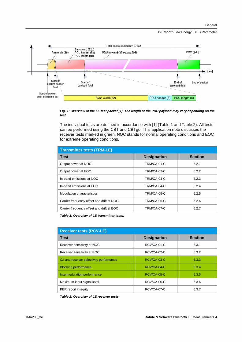
General
Bluetooth Low Energy (BLE) Parameter
1MA200_3e Rohde amp Schwarz Bluetooth LE Measurements 4
Fig 1 Overview of the LE test packet [1] The length of the PDU payload may vary depending on the
test
The individual tests are defined in accordance with [1] (Table 1 and Table 2) All tests
can be performed using the CBT and CBTgo This application note discusses the
receiver tests marked in green NOC stands for normal operating conditions and EOC
for extreme operating conditions
Transmitter tests (TRM-LE)
Test Designation Section
Output power at NOC TRMCA-01-C 621
Output power at EOC TRMCA-02-C 622
In-band emissions at NOC TRMCA-03-C 623
In-band emissions at EOC TRMCA-04-C 624
Modulation characteristics TRMCA-05-C 625
Carrier frequency offset and drift at NOC TRMCA-06-C 626
Carrier frequency offset and drift at EOC TRMCA-07-C 627
Table 1 Overview of LE transmitter tests
Receiver tests (RCV-LE)
Test Designation Section
Receiver sensitivity at NOC RCVCA-01-C 631
Receiver sensitivity at EOC RCVCA-02-C 632
CI and receiver selectivity performance RCVCA-03-C 633
Blocking performance RCVCA-04-C 634
Intermodulation performance RCVCA-05-C 635
Maximum input signal level RCVCA-06-C 636
PER report integrity RCVCA-07-C 637
Table 2 Overview of LE receiver tests
General
CBTgo
1MA200_3e Rohde amp Schwarz Bluetooth LE Measurements 5
Direct test mode
Low energy tests are performed in a direct test mode an RF connection is not made
In the test the DUT is put into the direct test mode via a local serial interface Test
commands such as the frequency to be tested or reading out the properly received
packets during RX tests run via an external interface The CBT can send these
commands via RS-232-C (COM port)
22 CBTgo
CBTgo is a PC software application for remote control of the CBT The software can be
downloaded free-of-charge from the Rohde amp Schwarz website Using CBTgo you can
conveniently create any desired test sequences by configuring and combining
selectable test modules This requires no knowledge of remote programming The
software generates measurement reports at the press of a button Reports can be
stored in various formats
CBTgo offers a number of sample sequences eg for automatically performing the
various Bluetooth RF test cases Reports of remote commands can also be output
stating the times of the individual steps and such reports can be copied to the
Windows clipboard for further use The software allows a large number of graphical
elements to be integrated into the measurement report and is thus a valuable tool in
RampD and product verification
221 PC Hardware and Software Requirements
Hardware requirements
CPU at least 300 MHz
RAM at least 64 Mbyte
Monitor SVGA with 800 x 600 pixels or higher
Hard disk 50 Mbyte available space
Peripherals National Instruments GPIB-bus or RS-232-C interface mouse
Software requirements
Windows 98ME2000XP7
CBTgo V220 with V220 Bluetooth modules or later
General
CBTgo
1MA200_3e Rohde amp Schwarz Bluetooth LE Measurements 6
222 Operation of CBTgo
Please refer to the CBTgo manual [2] for information on how to connect the computer with the CBT as well as how to install start and operate CBTgo
2221 Preparing for Operation
Setting the GPIB parameters in CBTgo
The GPIB parameters of the CBT can be set via CONFIGURATION|REMOTE PORT CBTgo uses auxiliary channels in order to communicate with additional devices To configure an additional device open the Configuration menu (Fig 2) and select an Auxiliary GPIB Port A window with further parameters will open (Fig 3)
Fig 2 Configuration menu of CBTgo Set the auxiliary port and the BT Low Energy device mode
General
CBTgo
1MA200_3e Rohde amp Schwarz Bluetooth LE Measurements 7
Fig 3 Auxiliary GPIB Port x
The device name entered under Auxiliary GPIB Port x must be identical to the name entered in the Bluetooth modules for the individual tests The usual GPIB parameters can be set Note that Enable Port must be enabled
Setting the reference frequency in CBTgo
Via the Basic Initializing module the CBT can be synchronized with other equipment
using a 10 MHz clock signal For this purpose enable External 10 MHz Reference
(Fig 6) and connect a BNC cable between the REF OUT output of a
generatoranalyzer and the REF IN socket of the CBT
Setting the LE device mode in CBTgo
In low energy mode the individual Bluetooth products are not controlled via signaling
but rather must be controlled directly via an interface To make the settings for this
select BT Low Energy Device in the CBTgo Configuration menu (see Fig 4 and Fig 5)
General
CBTgo
1MA200_3e Rohde amp Schwarz Bluetooth LE Measurements 8
Fig 4 Setting the LE device mode
Fig 5 Configuration CBT LE DUT interface
Measuring the attenuation values
To obtain correct results the attenuation between the CBT and the DUT must be measured and entered into the BT Call Setup module Likewise the attenuation between the DUT and the signal generator(s) andor the spectrum analyzer must be measured and entered into the appropriate module(s) Rohde amp Schwarz also offers the free-of-charge FreRes software which allows you to record the frequency response It is available under httpwwwrohde-schwarzcomappnote1MA09
General
CBTgo
1MA200_3e Rohde amp Schwarz Bluetooth LE Measurements 9
2222 Required Standard CBTgo Modules
For proper operation all new modules presented here require other CBTgo modules
For these basic modules detailed descriptions already exist (see [3]) therefore only
the main settings will be described in this document
Each test sequence requires the Basic Initializing and the BT Low Energy
Connection Setup modules
Basic Initializing must be the first module of every sequence Please enable the
Bluetooth Low Energy function group here
Fig 6 Basic Initializing module
The Bluetooth LE Connection Setup module is required at the start of each Bluetooth
low energy test sequence (after Basic Initializing) The main parameters for setting up
a connection to a Bluetooth low energy device are set in this module
Fig 7 Bluetooth low energy connection setup
Besides the attenuation parameters you can either set the Autoranging mode or enter
a maximum level manually
Stipulated Measurements
CI and Receiver Selectivity Performance (RCV-LECA03C)
1MA200_3e Rohde amp Schwarz Bluetooth LE Measurements 10
3 Stipulated Measurements
31 CI and Receiver Selectivity Performance
(RCV-LECA03C)
This test verifies the receiver performance of the DUT in presence of a Bluetooth
co-adjacent channel interferer within the Bluetooth band The result is obtained by
means of a packet error rate (PER) measurement
The wanted signal is transmitted on a single channel in non-hopping mode A
Bluetooth interferer is likewise generated on a single channel coupled in and the PER
is determined In the next step the Bluetooth interferer is generated on all channels
one after the other and the PER is measured for each interferer channel The
complete test sequence is repeated twice ie the PER measurement is performed with
the wanted signal on three channels in total (Fig 8)
Fig 8 CI performance For the three individual channels the packet error rate in the presence of a
Bluetooth interferer inside the Bluetooth band is measured The measurement is repeated after
shifting the interferer by 1 MHz
The Bluetooth test specification defines the following settings
DUT in direct RX mode
Hopping off (RX on single channel)
Three channels (0 19 39)
Test packets with 37 octet PRBS9 payload
Interferer GFSK (modulation index 05) with PRBS15 on all Bluetooth channels in
consecutive order
1500 packets
Wanted input level at EUT 67 dBm
For levels see Table 3
Stipulated Measurements
CI and Receiver Selectivity Performance (RCV-LECA03C)
1MA200_3e Rohde amp Schwarz Bluetooth LE Measurements 11
CI level settings
Interference signal frequency Interferer
level (abs)
CI level Wanted
signal (abs)
Co-channel
(f RX = f Interference )
ndash88 dBm 21 dB ndash67 dBm
Adjacent channel
(f Interference = f RX plusmn 1 MHz )
ndash82 dBm 15 dB ndash67 dBm
Adjacent channel
(f Interference = f RX plusmn 2 MHz )
ndash50 dBm ndash17 dB ndash67 dBm
Adjacent channel
(f Interference = f RX plusmn (3 + n) MHz )
ndash40 dBm ndash27 dB ndash67 dBm
Image frequency
(f Interference = f Image )
ndash58 dBm ndash9 dB ndash67 dBm
Adjacent channel to image frequency
(f Interference = f Image plusmn 1 MHz )
ndash52 dBm ndash15 dB ndash67 dBm
Table 3 CI and receiver selectivity test parameter settings [1]
Results
For all measurements the PER must be better than 308 for a minimum of 1500
packets
For each of the three wanted channels the PER may exceed 308 for five
interferer frequencies spaced ge 2 MHz from the carrier and spaced ge 1 MHz from
the image frequency
For the interferer frequencies (max five) at which the PER limit is exceeded the
PER is measured in a second test run with a relaxed CI of 17 dB The PER limit
is again 308
Test setup
Fig 9 shows a typical test setup The CBT and the DUT are connected to each other
by a combiner via which the interference signal from a Bluetooth generator is coupled
in If the DUT transmits at high power levels an attenuator may be inserted to protect
the generator
Stipulated Measurements
CI and Receiver Selectivity Performance (RCV-LECA03C)
1MA200_3e Rohde amp Schwarz Bluetooth LE Measurements 12
Fig 9 Test setup for CI performance measurement
Measuring equipment and accessories
CBT tester SMx (SMU SMJ SMATE SMBV) signal generator
Resistive combiner up to 25 GHz (eg Weinschel 1515 1)
Attenuator up to 25 GHz (eg Suhner) The measurement is performed using the BT LE CI Performance module in CBTgo (Fig 10)
Stipulated Measurements
CI and Receiver Selectivity Performance (RCV-LECA03C)
1MA200_3e Rohde amp Schwarz Bluetooth LE Measurements 13
Fig 10 BT Low Energy CI Performance module in CBTgo
Under Test mode you can select the test packet payload type and the three RX
channels with different manufacturer-specific Image frequencies in Megahertz The
reference sensitivity is according to the specification ndash67 dBm (see Table 3)
Under Generator BT the auxiliary device name is to be entered The name must be
identical to that entered for Auxiliary GPIB Port x in the Configuration menu
Moreover the path loss between the generator and the DUT can be entered
Under Measurements you can enter the PER limit and the number of packets If Early
Exit is enabled the measurement is exited if more then five spurious frequencies are
detected You can show all measurement values with enabling Show detailed Values
The different levels are set automatically for measurements on the image-frequency
channel (see Table 3) The default settings comply with the test specification
CBTgo automatically performs the test on the three channels with the selected
generator settings
Stipulated Measurements
CI and Receiver Selectivity Performance (RCV-LECA03C)
1MA200_3e Rohde amp Schwarz Bluetooth LE Measurements 14
In the first test run all frequencies with a PER above the set limit are determined and
displayed In the second test run which is also performed automatically the DUTs
performance at these frequencies is retested with a CI of 17 dB This only takes
place for a maximum of five interference frequencies that are not
Co-channel
Adjacent channel plusmn 1 MHz
Image frequency
Adjacent channel to image frequency
With the settings in compliance with the test specification the measurement time is at
least four minutes (approx 1 second per PER measurement times 79 interferer channels times
three wanted channels)
Fig 11 shows a typical CI performance test report
Fig 11 CI performance test reports CBTgo shows the measurement results at the detected
spurious frequencies and a summary The repeated measurements with relaxed conditions is also
shown
Stipulated Measurements
Blocking Performance (RCV-LECA04C)
1MA200_3e Rohde amp Schwarz Bluetooth LE Measurements 15
32 Blocking Performance (RCV-LECA04C)
This measurement determines the receiver quality of the DUT if a continuous-wave
(CW) interferer is present outside the Bluetooth band The result is obtained by means
of a packet error rate (PER) measurement
The wanted signal is transmitted on a single channel in non-hopping mode A CW
interferer is likewise generated on a single channel coupled in and the BER is
determined In the next step the CW interferer is generated at intervals in consecutive
order over a specific frequency range and the PER is determined for each interferer
frequency (Fig 12)
Fig 12 Blocking performance For one channel the packet error rate in the presence of a CW
interferer outside the Bluetooth band is measured The measurement is repeated after shifting the
interferer by the frequency resolution
The Bluetooth test specification defines the following settings
DUT in direct RX mode
Hopping off (RX on single channel)
One channel (19)
Test packets with 37 octet PRBS9 payload
Interferer CW signal for levels and frequency ranges see Table 4
1500 packets
Wanted input level at EUT 67 dBm
Stipulated Measurements
Blocking Performance (RCV-LECA04C)
1MA200_3e Rohde amp Schwarz Bluetooth LE Measurements 16
Blocking level settings
Interference signal frequency Wanted
signal level
Blocking
signal level
Frequency
resolution
30 MHz to 2000 MHz ndash67 dBm ndash30 dBm 10 MHz
2003 MHz to 2399 MHz ndash67 dBm ndash35 dBm 3 MHz
2484 MHz to 2997 MHz ndash67 dBm ndash35 dBm 3 MHz
3000 MHz to 1275 GHz ndash67 dBm ndash30 dBm 25 MHz
Table 4 Blocking performance parameters first test run
Results
1st test run At each interferer frequency 1500 packets are measured The
frequencies at which a PER gt 308 is obtained are recorded The number of
frequencies recorded here must not exceed ten
2nd test run At each frequency recorded during the 1st test run 1500 packets are
measured at reduced interferer levels of ndash50 dBm The frequencies at which a
PER gt 308 is obtained are again recorded The PER limit may be exceeded for
a maximum of three frequencies
Test setup
Fig 13 shows a typical test setup The CBT and the DUT are connected to each other
by a combiner via which the interference signal from a CW generator is coupled in If
the DUT transmits at high power levels an attenuator may be inserted to protect the
generator
Fig 13 Test setup for blocking performance measurement
Stipulated Measurements
Blocking Performance (RCV-LECA04C)
1MA200_3e Rohde amp Schwarz Bluetooth LE Measurements 17
Measuring equipment and accessories
CBT tester SMx (SMF SMB SMR) generator up to 1275 GHz
Resistive combiner up to 1275 GHz (eg Weinschel 1515 1)
Attenuator up to 1275 GHz (eg Suhner) The measurement is performed using the BT Low Energy Blocking Performance module in CBTgo (Fig 14)
Fig 14 CBTgo BT Low Energy Blocking Performance module
Stipulated Measurements
Blocking Performance (RCV-LECA04C)
1MA200_3e Rohde amp Schwarz Bluetooth LE Measurements 18
Under Test mode you can select the test packet payload type The RX frequency of the measurement channel can be set The reference sensitivity level can be modified as required According to the specification this must be ndash67 dBm Under Generator CW the auxiliary device name is to be entered The name must be identical to that entered for Auxiliary GPIB Port x in the Configuration menu Moreover the path loss between the generator and the DUT can be set Under Blocking performance parameters the generator level as well as a start and a stop frequency can be entered in four columns In addition you can enter the measurement frequency resolution The default settings are the four ranges according to the specification (see Table 4) Under Measurements you can enter the PER limit the number of packets and the allowed exceptions for the two runs separately If Early Exit is enabled the measurement is exited if more then ten spurious frequencies are detected CBTgo automatically performs the test using the selected generator settings With the settings in compliance with the test specification the measurement time is at least 15 minutes (1 s per PER measurement times approx 890 interferer channels in the 1st test run) Fig 15 shows a typical entry in the test report
Stipulated Measurements
Blocking Performance (RCV-LECA04C)
1MA200_3e Rohde amp Schwarz Bluetooth LE Measurements 19
Fig 15 Blocking performance test report CBTgo shows the measurement results at the detected
spurious frequencies and a summary for the different sections The repeated measurements with
relaxed conditions are also shown
Stipulated Measurements
Intermodulation Performance (RCV-LECA05C)
1MA200_3e Rohde amp Schwarz Bluetooth LE Measurements 20
33 Intermodulation Performance (RCV-LECA05C)
This measurement verifies the intermodulation performance of the DUTs receiver A
PER measurement is performed using two interferers that cause intermodulation at the
DUTs receive frequency
The wanted signal is transmitted on a single channel in non-hopping mode A CW
interferer spaced +n MHz and a Bluetooth interferer spaced +2n MHz from the wanted
signal are generated coupled in and the PER is determined The measurement is
then performed with the interferers at ndashn MHz and ndash2n MHz The two measurements
are repeated on two more wanted channels (Fig 16)
Fig 16 Intermodulation performance For each of three channels the packet error rate in the
presence of a CW interferer in a distance n and in the presence of a Bluetooth interferer in a distance
2n is measured
The Bluetooth test specification defines the following settings
Hopping off (RX on single channel)
Three channels (0 19 39)
PRBS9
Wanted signal level at ndash64 dBm
n = 3 4 or 5 (defined by manufacturer)
Bluetooth interferer low energy GFSK with PRBS15 spaced plusmn2n MHz from wanted
signal level ndash50 dBm
CW interferer spaced plusmnn MHz from wanted signal level ndash50 dBm
1500 packets
Result
A PER of 308 must be obtained for each of the three channels
Stipulated Measurements
Intermodulation Performance (RCV-LECA05C)
1MA200_3e Rohde amp Schwarz Bluetooth LE Measurements 21
Test setup
The two interferer signals required in this measurement are supplied via two generator
paths that are combined via a hybrid combiner The resulting signal is coupled into the
line connecting the CBT and the DUT via a second hybrid combiner If a dual-channel
SMU is used one generator is sufficient (Fig 17) otherwise two generators are
required (Fig 18)
Fig 17 Test setup 1 for intermodulation performance measurement using one generator
Stipulated Measurements
Intermodulation Performance (RCV-LECA05C)
1MA200_3e Rohde amp Schwarz Bluetooth LE Measurements 22
Fig 18 Test setup 2 for intermodulation performance using two generators
Measuring equipment and accessories
CBT tester SMU or SMJ + SMF or SMB or SMR signal generators
Two hybrid combiners (eg Minicircuits ZFSC 2 2500)
The measurement is performed using the BT Low Energy Intermodulation
Performance module in CBTgo (Fig 19)
Stipulated Measurements
Intermodulation Performance (RCV-LECA05C)
1MA200_3e Rohde amp Schwarz Bluetooth LE Measurements 23
Fig 19 CBTgo BT Low Energy Intermodulation Performance module
Under Test Mode you can select the test packet payload type The RX frequencies of the three channels can be set The reference sensitivity level can be modified as required According to the specification this must be ndash 64 dBm
Under Generator 1 and Generator 2 the auxiliary device name is to be entered The
name must be identical to that entered for Auxiliary GPIB Port x in the Configuration
menu The intermodulation distance n (spacing from wanted signal) must be selected
Moreover the path loss between the generator and the DUT as well as the
interference level can be entered for each generator A second generator can be
included in the test setup if the first generator does not offer dual-channel capability
Stipulated Measurements
Intermodulation Performance (RCV-LECA05C)
1MA200_3e Rohde amp Schwarz Bluetooth LE Measurements 24
Under Measurements you can enter the PER limit and the number of packets The
default settings comply with the test specification
CBTgo automatically performs the test on the three channels using the selected
generator settings
Fig 20 shows a typical entry in the test report
Fig 20 Low energy intermodulation performance test report
Appendix
References
1MA200_3e Rohde amp Schwarz Bluetooth LE Measurements 25
4 Appendix
41 References
[1] Bluetooth Test amp Interoperability Working Group Bluetooth Low Energy RF PHY
Test Specification RF-PHYTS402 122012 Bluetooth SIG Inc
[2] Rohde amp Schwarz Manual for Windows Application CBTgo (V170)
[3] Rohde amp Schwarz Measurements on Bluetooth Products using
RampS CMU200CBT and CMUgoCBTgo Application Note 1CM50 102006
[4] Rohde amp Schwarz Bluetooth Measurements Using CBTgo Additional Tests Application Note 1MA106 022013
42 Additional Information
Please send your comments and suggestions regarding this application note to
TM-Applicationsrohde-schwarzcom
Visit the CBTgo website at
httpwww2rohde-
schwarzcomenproductstest_and_measurementmobile_radioCBT_CBT32-|-
Tools-|-67-|-1459html
or as a registered user in GLORIS the CMU Customer Web at
httpsextranetrohde-schwarzcom
Appendix
Ordering Information
1MA200_3e Rohde amp Schwarz Bluetooth LE Measurements 26
43 Ordering Information
Ordering information
Bluetooth tester
CBT Bluetooth tester with display 1153900035
CBT32 Bluetooth tester without display 1153900032
CBT-K57 Bluetooth Low Energy 1170410202
Vector signal generator
SMU200A Vector Signal Generator 1141200502
SMU-B9 Baseband Generator 128 Msample 1161076602
SMU-B10 Baseband Generator 64 Msample 1141700702
SMU-B11 Baseband Generator 16 Msample 1159841102
SMU-B13 Baseband Main Module 1141800304
SMU-B10x RF Path A
SMU-B20x RF Path B
SMW200A Vector Signal Generator 1412000002
SMW-B10 Baseband Generator with ARB
(64 Msample) and Digital Modulation
(realtime) 120 MHz RF bandwidth
1413120002
SMW-B13 Baseband Main Module one IQ path to RF 1413280702
SMW-B10x RF Path A
SMW-B20x RF Path B
SMBV100A Vector Signal Generator 1407600402
Signal generator
SMF100A Microwave Signal Generator
up to 435 GHz
1167000002
SMB100A RF and Microwave Signal Generator
up to 1275 GHz
1406600002
xx stands for the different frequency ranges (eg 1155500126 MHz to 26 GHz
Note Available options are not listed in detail
Please contact your local Rohde amp Schwarz sales office for further assistance
About Rohde amp Schwarz
Rohde amp Schwarz is an independent group
of companies specializing in electronics It is
a leading supplier of solutions in the fields of
test and measurement broadcasting
radiomonitoring and radiolocation as well as
secure communications Established more
than 75 years ago Rohde amp Schwarz has a
global presence and a dedicated service
network in over 70 countries Company
headquarters are in Munich Germany
Environmental commitment
Energy-efficient products
Continuous improvement in
environmental sustainability
ISO 14001-certified environmental
management system
Regional contact
Europe Africa Middle East
+49 89 4129 12345
customersupportrohde-schwarzcom North America
1-888-TEST-RSA (1-888-837-8772)
customersupportrsarohde-schwarzcom Latin America
+1-410-910-7988
customersupportlarohde-schwarzcom AsiaPacific
+65 65 13 04 88
customersupportasiarohde-schwarzcom
This application note and the supplied
programs may only be used subject to the
conditions of use set forth in the download
area of the Rohde amp Schwarz website
RampSreg is a registered trademark of Rohde amp Schwarz GmbH amp Co KG Trade names are trademarks of the owners
Rohde amp Schwarz GmbH amp Co KG
Muumlhldorfstraszlige 15 | D - 81671 Muumlnchen
Phone + 49 89 4129 - 0 | Fax + 49 89 4129 ndash 13777
wwwrohde-schwarzcom
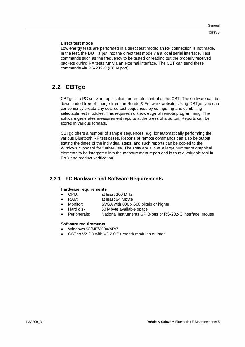
General
CBTgo
1MA200_3e Rohde amp Schwarz Bluetooth LE Measurements 5
Direct test mode
Low energy tests are performed in a direct test mode an RF connection is not made
In the test the DUT is put into the direct test mode via a local serial interface Test
commands such as the frequency to be tested or reading out the properly received
packets during RX tests run via an external interface The CBT can send these
commands via RS-232-C (COM port)
22 CBTgo
CBTgo is a PC software application for remote control of the CBT The software can be
downloaded free-of-charge from the Rohde amp Schwarz website Using CBTgo you can
conveniently create any desired test sequences by configuring and combining
selectable test modules This requires no knowledge of remote programming The
software generates measurement reports at the press of a button Reports can be
stored in various formats
CBTgo offers a number of sample sequences eg for automatically performing the
various Bluetooth RF test cases Reports of remote commands can also be output
stating the times of the individual steps and such reports can be copied to the
Windows clipboard for further use The software allows a large number of graphical
elements to be integrated into the measurement report and is thus a valuable tool in
RampD and product verification
221 PC Hardware and Software Requirements
Hardware requirements
CPU at least 300 MHz
RAM at least 64 Mbyte
Monitor SVGA with 800 x 600 pixels or higher
Hard disk 50 Mbyte available space
Peripherals National Instruments GPIB-bus or RS-232-C interface mouse
Software requirements
Windows 98ME2000XP7
CBTgo V220 with V220 Bluetooth modules or later
General
CBTgo
1MA200_3e Rohde amp Schwarz Bluetooth LE Measurements 6
222 Operation of CBTgo
Please refer to the CBTgo manual [2] for information on how to connect the computer with the CBT as well as how to install start and operate CBTgo
2221 Preparing for Operation
Setting the GPIB parameters in CBTgo
The GPIB parameters of the CBT can be set via CONFIGURATION|REMOTE PORT CBTgo uses auxiliary channels in order to communicate with additional devices To configure an additional device open the Configuration menu (Fig 2) and select an Auxiliary GPIB Port A window with further parameters will open (Fig 3)
Fig 2 Configuration menu of CBTgo Set the auxiliary port and the BT Low Energy device mode
General
CBTgo
1MA200_3e Rohde amp Schwarz Bluetooth LE Measurements 7
Fig 3 Auxiliary GPIB Port x
The device name entered under Auxiliary GPIB Port x must be identical to the name entered in the Bluetooth modules for the individual tests The usual GPIB parameters can be set Note that Enable Port must be enabled
Setting the reference frequency in CBTgo
Via the Basic Initializing module the CBT can be synchronized with other equipment
using a 10 MHz clock signal For this purpose enable External 10 MHz Reference
(Fig 6) and connect a BNC cable between the REF OUT output of a
generatoranalyzer and the REF IN socket of the CBT
Setting the LE device mode in CBTgo
In low energy mode the individual Bluetooth products are not controlled via signaling
but rather must be controlled directly via an interface To make the settings for this
select BT Low Energy Device in the CBTgo Configuration menu (see Fig 4 and Fig 5)
General
CBTgo
1MA200_3e Rohde amp Schwarz Bluetooth LE Measurements 8
Fig 4 Setting the LE device mode
Fig 5 Configuration CBT LE DUT interface
Measuring the attenuation values
To obtain correct results the attenuation between the CBT and the DUT must be measured and entered into the BT Call Setup module Likewise the attenuation between the DUT and the signal generator(s) andor the spectrum analyzer must be measured and entered into the appropriate module(s) Rohde amp Schwarz also offers the free-of-charge FreRes software which allows you to record the frequency response It is available under httpwwwrohde-schwarzcomappnote1MA09
General
CBTgo
1MA200_3e Rohde amp Schwarz Bluetooth LE Measurements 9
2222 Required Standard CBTgo Modules
For proper operation all new modules presented here require other CBTgo modules
For these basic modules detailed descriptions already exist (see [3]) therefore only
the main settings will be described in this document
Each test sequence requires the Basic Initializing and the BT Low Energy
Connection Setup modules
Basic Initializing must be the first module of every sequence Please enable the
Bluetooth Low Energy function group here
Fig 6 Basic Initializing module
The Bluetooth LE Connection Setup module is required at the start of each Bluetooth
low energy test sequence (after Basic Initializing) The main parameters for setting up
a connection to a Bluetooth low energy device are set in this module
Fig 7 Bluetooth low energy connection setup
Besides the attenuation parameters you can either set the Autoranging mode or enter
a maximum level manually
Stipulated Measurements
CI and Receiver Selectivity Performance (RCV-LECA03C)
1MA200_3e Rohde amp Schwarz Bluetooth LE Measurements 10
3 Stipulated Measurements
31 CI and Receiver Selectivity Performance
(RCV-LECA03C)
This test verifies the receiver performance of the DUT in presence of a Bluetooth
co-adjacent channel interferer within the Bluetooth band The result is obtained by
means of a packet error rate (PER) measurement
The wanted signal is transmitted on a single channel in non-hopping mode A
Bluetooth interferer is likewise generated on a single channel coupled in and the PER
is determined In the next step the Bluetooth interferer is generated on all channels
one after the other and the PER is measured for each interferer channel The
complete test sequence is repeated twice ie the PER measurement is performed with
the wanted signal on three channels in total (Fig 8)
Fig 8 CI performance For the three individual channels the packet error rate in the presence of a
Bluetooth interferer inside the Bluetooth band is measured The measurement is repeated after
shifting the interferer by 1 MHz
The Bluetooth test specification defines the following settings
DUT in direct RX mode
Hopping off (RX on single channel)
Three channels (0 19 39)
Test packets with 37 octet PRBS9 payload
Interferer GFSK (modulation index 05) with PRBS15 on all Bluetooth channels in
consecutive order
1500 packets
Wanted input level at EUT 67 dBm
For levels see Table 3
Stipulated Measurements
CI and Receiver Selectivity Performance (RCV-LECA03C)
1MA200_3e Rohde amp Schwarz Bluetooth LE Measurements 11
CI level settings
Interference signal frequency Interferer
level (abs)
CI level Wanted
signal (abs)
Co-channel
(f RX = f Interference )
ndash88 dBm 21 dB ndash67 dBm
Adjacent channel
(f Interference = f RX plusmn 1 MHz )
ndash82 dBm 15 dB ndash67 dBm
Adjacent channel
(f Interference = f RX plusmn 2 MHz )
ndash50 dBm ndash17 dB ndash67 dBm
Adjacent channel
(f Interference = f RX plusmn (3 + n) MHz )
ndash40 dBm ndash27 dB ndash67 dBm
Image frequency
(f Interference = f Image )
ndash58 dBm ndash9 dB ndash67 dBm
Adjacent channel to image frequency
(f Interference = f Image plusmn 1 MHz )
ndash52 dBm ndash15 dB ndash67 dBm
Table 3 CI and receiver selectivity test parameter settings [1]
Results
For all measurements the PER must be better than 308 for a minimum of 1500
packets
For each of the three wanted channels the PER may exceed 308 for five
interferer frequencies spaced ge 2 MHz from the carrier and spaced ge 1 MHz from
the image frequency
For the interferer frequencies (max five) at which the PER limit is exceeded the
PER is measured in a second test run with a relaxed CI of 17 dB The PER limit
is again 308
Test setup
Fig 9 shows a typical test setup The CBT and the DUT are connected to each other
by a combiner via which the interference signal from a Bluetooth generator is coupled
in If the DUT transmits at high power levels an attenuator may be inserted to protect
the generator
Stipulated Measurements
CI and Receiver Selectivity Performance (RCV-LECA03C)
1MA200_3e Rohde amp Schwarz Bluetooth LE Measurements 12
Fig 9 Test setup for CI performance measurement
Measuring equipment and accessories
CBT tester SMx (SMU SMJ SMATE SMBV) signal generator
Resistive combiner up to 25 GHz (eg Weinschel 1515 1)
Attenuator up to 25 GHz (eg Suhner) The measurement is performed using the BT LE CI Performance module in CBTgo (Fig 10)
Stipulated Measurements
CI and Receiver Selectivity Performance (RCV-LECA03C)
1MA200_3e Rohde amp Schwarz Bluetooth LE Measurements 13
Fig 10 BT Low Energy CI Performance module in CBTgo
Under Test mode you can select the test packet payload type and the three RX
channels with different manufacturer-specific Image frequencies in Megahertz The
reference sensitivity is according to the specification ndash67 dBm (see Table 3)
Under Generator BT the auxiliary device name is to be entered The name must be
identical to that entered for Auxiliary GPIB Port x in the Configuration menu
Moreover the path loss between the generator and the DUT can be entered
Under Measurements you can enter the PER limit and the number of packets If Early
Exit is enabled the measurement is exited if more then five spurious frequencies are
detected You can show all measurement values with enabling Show detailed Values
The different levels are set automatically for measurements on the image-frequency
channel (see Table 3) The default settings comply with the test specification
CBTgo automatically performs the test on the three channels with the selected
generator settings
Stipulated Measurements
CI and Receiver Selectivity Performance (RCV-LECA03C)
1MA200_3e Rohde amp Schwarz Bluetooth LE Measurements 14
In the first test run all frequencies with a PER above the set limit are determined and
displayed In the second test run which is also performed automatically the DUTs
performance at these frequencies is retested with a CI of 17 dB This only takes
place for a maximum of five interference frequencies that are not
Co-channel
Adjacent channel plusmn 1 MHz
Image frequency
Adjacent channel to image frequency
With the settings in compliance with the test specification the measurement time is at
least four minutes (approx 1 second per PER measurement times 79 interferer channels times
three wanted channels)
Fig 11 shows a typical CI performance test report
Fig 11 CI performance test reports CBTgo shows the measurement results at the detected
spurious frequencies and a summary The repeated measurements with relaxed conditions is also
shown
Stipulated Measurements
Blocking Performance (RCV-LECA04C)
1MA200_3e Rohde amp Schwarz Bluetooth LE Measurements 15
32 Blocking Performance (RCV-LECA04C)
This measurement determines the receiver quality of the DUT if a continuous-wave
(CW) interferer is present outside the Bluetooth band The result is obtained by means
of a packet error rate (PER) measurement
The wanted signal is transmitted on a single channel in non-hopping mode A CW
interferer is likewise generated on a single channel coupled in and the BER is
determined In the next step the CW interferer is generated at intervals in consecutive
order over a specific frequency range and the PER is determined for each interferer
frequency (Fig 12)
Fig 12 Blocking performance For one channel the packet error rate in the presence of a CW
interferer outside the Bluetooth band is measured The measurement is repeated after shifting the
interferer by the frequency resolution
The Bluetooth test specification defines the following settings
DUT in direct RX mode
Hopping off (RX on single channel)
One channel (19)
Test packets with 37 octet PRBS9 payload
Interferer CW signal for levels and frequency ranges see Table 4
1500 packets
Wanted input level at EUT 67 dBm
Stipulated Measurements
Blocking Performance (RCV-LECA04C)
1MA200_3e Rohde amp Schwarz Bluetooth LE Measurements 16
Blocking level settings
Interference signal frequency Wanted
signal level
Blocking
signal level
Frequency
resolution
30 MHz to 2000 MHz ndash67 dBm ndash30 dBm 10 MHz
2003 MHz to 2399 MHz ndash67 dBm ndash35 dBm 3 MHz
2484 MHz to 2997 MHz ndash67 dBm ndash35 dBm 3 MHz
3000 MHz to 1275 GHz ndash67 dBm ndash30 dBm 25 MHz
Table 4 Blocking performance parameters first test run
Results
1st test run At each interferer frequency 1500 packets are measured The
frequencies at which a PER gt 308 is obtained are recorded The number of
frequencies recorded here must not exceed ten
2nd test run At each frequency recorded during the 1st test run 1500 packets are
measured at reduced interferer levels of ndash50 dBm The frequencies at which a
PER gt 308 is obtained are again recorded The PER limit may be exceeded for
a maximum of three frequencies
Test setup
Fig 13 shows a typical test setup The CBT and the DUT are connected to each other
by a combiner via which the interference signal from a CW generator is coupled in If
the DUT transmits at high power levels an attenuator may be inserted to protect the
generator
Fig 13 Test setup for blocking performance measurement
Stipulated Measurements
Blocking Performance (RCV-LECA04C)
1MA200_3e Rohde amp Schwarz Bluetooth LE Measurements 17
Measuring equipment and accessories
CBT tester SMx (SMF SMB SMR) generator up to 1275 GHz
Resistive combiner up to 1275 GHz (eg Weinschel 1515 1)
Attenuator up to 1275 GHz (eg Suhner) The measurement is performed using the BT Low Energy Blocking Performance module in CBTgo (Fig 14)
Fig 14 CBTgo BT Low Energy Blocking Performance module
Stipulated Measurements
Blocking Performance (RCV-LECA04C)
1MA200_3e Rohde amp Schwarz Bluetooth LE Measurements 18
Under Test mode you can select the test packet payload type The RX frequency of the measurement channel can be set The reference sensitivity level can be modified as required According to the specification this must be ndash67 dBm Under Generator CW the auxiliary device name is to be entered The name must be identical to that entered for Auxiliary GPIB Port x in the Configuration menu Moreover the path loss between the generator and the DUT can be set Under Blocking performance parameters the generator level as well as a start and a stop frequency can be entered in four columns In addition you can enter the measurement frequency resolution The default settings are the four ranges according to the specification (see Table 4) Under Measurements you can enter the PER limit the number of packets and the allowed exceptions for the two runs separately If Early Exit is enabled the measurement is exited if more then ten spurious frequencies are detected CBTgo automatically performs the test using the selected generator settings With the settings in compliance with the test specification the measurement time is at least 15 minutes (1 s per PER measurement times approx 890 interferer channels in the 1st test run) Fig 15 shows a typical entry in the test report
Stipulated Measurements
Blocking Performance (RCV-LECA04C)
1MA200_3e Rohde amp Schwarz Bluetooth LE Measurements 19
Fig 15 Blocking performance test report CBTgo shows the measurement results at the detected
spurious frequencies and a summary for the different sections The repeated measurements with
relaxed conditions are also shown
Stipulated Measurements
Intermodulation Performance (RCV-LECA05C)
1MA200_3e Rohde amp Schwarz Bluetooth LE Measurements 20
33 Intermodulation Performance (RCV-LECA05C)
This measurement verifies the intermodulation performance of the DUTs receiver A
PER measurement is performed using two interferers that cause intermodulation at the
DUTs receive frequency
The wanted signal is transmitted on a single channel in non-hopping mode A CW
interferer spaced +n MHz and a Bluetooth interferer spaced +2n MHz from the wanted
signal are generated coupled in and the PER is determined The measurement is
then performed with the interferers at ndashn MHz and ndash2n MHz The two measurements
are repeated on two more wanted channels (Fig 16)
Fig 16 Intermodulation performance For each of three channels the packet error rate in the
presence of a CW interferer in a distance n and in the presence of a Bluetooth interferer in a distance
2n is measured
The Bluetooth test specification defines the following settings
Hopping off (RX on single channel)
Three channels (0 19 39)
PRBS9
Wanted signal level at ndash64 dBm
n = 3 4 or 5 (defined by manufacturer)
Bluetooth interferer low energy GFSK with PRBS15 spaced plusmn2n MHz from wanted
signal level ndash50 dBm
CW interferer spaced plusmnn MHz from wanted signal level ndash50 dBm
1500 packets
Result
A PER of 308 must be obtained for each of the three channels
Stipulated Measurements
Intermodulation Performance (RCV-LECA05C)
1MA200_3e Rohde amp Schwarz Bluetooth LE Measurements 21
Test setup
The two interferer signals required in this measurement are supplied via two generator
paths that are combined via a hybrid combiner The resulting signal is coupled into the
line connecting the CBT and the DUT via a second hybrid combiner If a dual-channel
SMU is used one generator is sufficient (Fig 17) otherwise two generators are
required (Fig 18)
Fig 17 Test setup 1 for intermodulation performance measurement using one generator
Stipulated Measurements
Intermodulation Performance (RCV-LECA05C)
1MA200_3e Rohde amp Schwarz Bluetooth LE Measurements 22
Fig 18 Test setup 2 for intermodulation performance using two generators
Measuring equipment and accessories
CBT tester SMU or SMJ + SMF or SMB or SMR signal generators
Two hybrid combiners (eg Minicircuits ZFSC 2 2500)
The measurement is performed using the BT Low Energy Intermodulation
Performance module in CBTgo (Fig 19)
Stipulated Measurements
Intermodulation Performance (RCV-LECA05C)
1MA200_3e Rohde amp Schwarz Bluetooth LE Measurements 23
Fig 19 CBTgo BT Low Energy Intermodulation Performance module
Under Test Mode you can select the test packet payload type The RX frequencies of the three channels can be set The reference sensitivity level can be modified as required According to the specification this must be ndash 64 dBm
Under Generator 1 and Generator 2 the auxiliary device name is to be entered The
name must be identical to that entered for Auxiliary GPIB Port x in the Configuration
menu The intermodulation distance n (spacing from wanted signal) must be selected
Moreover the path loss between the generator and the DUT as well as the
interference level can be entered for each generator A second generator can be
included in the test setup if the first generator does not offer dual-channel capability
Stipulated Measurements
Intermodulation Performance (RCV-LECA05C)
1MA200_3e Rohde amp Schwarz Bluetooth LE Measurements 24
Under Measurements you can enter the PER limit and the number of packets The
default settings comply with the test specification
CBTgo automatically performs the test on the three channels using the selected
generator settings
Fig 20 shows a typical entry in the test report
Fig 20 Low energy intermodulation performance test report
Appendix
References
1MA200_3e Rohde amp Schwarz Bluetooth LE Measurements 25
4 Appendix
41 References
[1] Bluetooth Test amp Interoperability Working Group Bluetooth Low Energy RF PHY
Test Specification RF-PHYTS402 122012 Bluetooth SIG Inc
[2] Rohde amp Schwarz Manual for Windows Application CBTgo (V170)
[3] Rohde amp Schwarz Measurements on Bluetooth Products using
RampS CMU200CBT and CMUgoCBTgo Application Note 1CM50 102006
[4] Rohde amp Schwarz Bluetooth Measurements Using CBTgo Additional Tests Application Note 1MA106 022013
42 Additional Information
Please send your comments and suggestions regarding this application note to
TM-Applicationsrohde-schwarzcom
Visit the CBTgo website at
httpwww2rohde-
schwarzcomenproductstest_and_measurementmobile_radioCBT_CBT32-|-
Tools-|-67-|-1459html
or as a registered user in GLORIS the CMU Customer Web at
httpsextranetrohde-schwarzcom
Appendix
Ordering Information
1MA200_3e Rohde amp Schwarz Bluetooth LE Measurements 26
43 Ordering Information
Ordering information
Bluetooth tester
CBT Bluetooth tester with display 1153900035
CBT32 Bluetooth tester without display 1153900032
CBT-K57 Bluetooth Low Energy 1170410202
Vector signal generator
SMU200A Vector Signal Generator 1141200502
SMU-B9 Baseband Generator 128 Msample 1161076602
SMU-B10 Baseband Generator 64 Msample 1141700702
SMU-B11 Baseband Generator 16 Msample 1159841102
SMU-B13 Baseband Main Module 1141800304
SMU-B10x RF Path A
SMU-B20x RF Path B
SMW200A Vector Signal Generator 1412000002
SMW-B10 Baseband Generator with ARB
(64 Msample) and Digital Modulation
(realtime) 120 MHz RF bandwidth
1413120002
SMW-B13 Baseband Main Module one IQ path to RF 1413280702
SMW-B10x RF Path A
SMW-B20x RF Path B
SMBV100A Vector Signal Generator 1407600402
Signal generator
SMF100A Microwave Signal Generator
up to 435 GHz
1167000002
SMB100A RF and Microwave Signal Generator
up to 1275 GHz
1406600002
xx stands for the different frequency ranges (eg 1155500126 MHz to 26 GHz
Note Available options are not listed in detail
Please contact your local Rohde amp Schwarz sales office for further assistance
About Rohde amp Schwarz
Rohde amp Schwarz is an independent group
of companies specializing in electronics It is
a leading supplier of solutions in the fields of
test and measurement broadcasting
radiomonitoring and radiolocation as well as
secure communications Established more
than 75 years ago Rohde amp Schwarz has a
global presence and a dedicated service
network in over 70 countries Company
headquarters are in Munich Germany
Environmental commitment
Energy-efficient products
Continuous improvement in
environmental sustainability
ISO 14001-certified environmental
management system
Regional contact
Europe Africa Middle East
+49 89 4129 12345
customersupportrohde-schwarzcom North America
1-888-TEST-RSA (1-888-837-8772)
customersupportrsarohde-schwarzcom Latin America
+1-410-910-7988
customersupportlarohde-schwarzcom AsiaPacific
+65 65 13 04 88
customersupportasiarohde-schwarzcom
This application note and the supplied
programs may only be used subject to the
conditions of use set forth in the download
area of the Rohde amp Schwarz website
RampSreg is a registered trademark of Rohde amp Schwarz GmbH amp Co KG Trade names are trademarks of the owners
Rohde amp Schwarz GmbH amp Co KG
Muumlhldorfstraszlige 15 | D - 81671 Muumlnchen
Phone + 49 89 4129 - 0 | Fax + 49 89 4129 ndash 13777
wwwrohde-schwarzcom
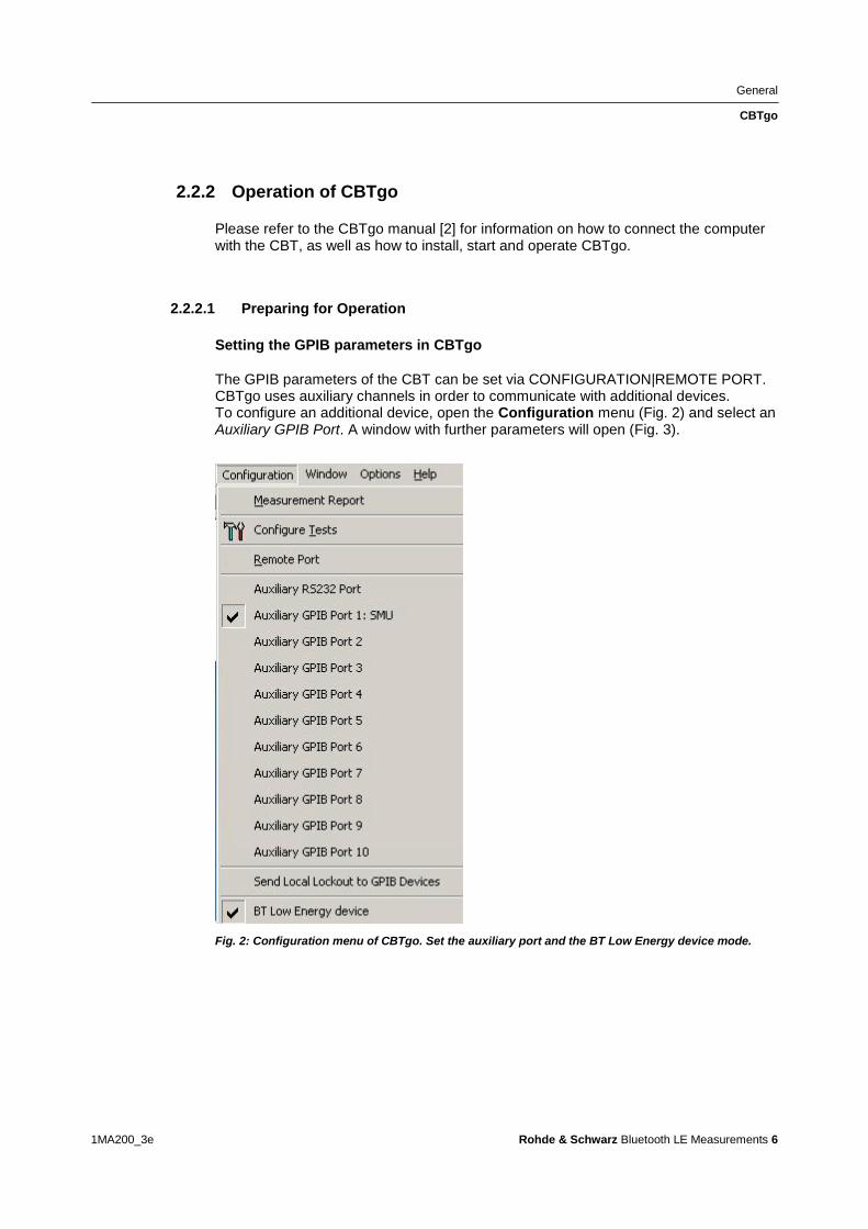
General
CBTgo
1MA200_3e Rohde amp Schwarz Bluetooth LE Measurements 6
222 Operation of CBTgo
Please refer to the CBTgo manual [2] for information on how to connect the computer with the CBT as well as how to install start and operate CBTgo
2221 Preparing for Operation
Setting the GPIB parameters in CBTgo
The GPIB parameters of the CBT can be set via CONFIGURATION|REMOTE PORT CBTgo uses auxiliary channels in order to communicate with additional devices To configure an additional device open the Configuration menu (Fig 2) and select an Auxiliary GPIB Port A window with further parameters will open (Fig 3)
Fig 2 Configuration menu of CBTgo Set the auxiliary port and the BT Low Energy device mode
General
CBTgo
1MA200_3e Rohde amp Schwarz Bluetooth LE Measurements 7
Fig 3 Auxiliary GPIB Port x
The device name entered under Auxiliary GPIB Port x must be identical to the name entered in the Bluetooth modules for the individual tests The usual GPIB parameters can be set Note that Enable Port must be enabled
Setting the reference frequency in CBTgo
Via the Basic Initializing module the CBT can be synchronized with other equipment
using a 10 MHz clock signal For this purpose enable External 10 MHz Reference
(Fig 6) and connect a BNC cable between the REF OUT output of a
generatoranalyzer and the REF IN socket of the CBT
Setting the LE device mode in CBTgo
In low energy mode the individual Bluetooth products are not controlled via signaling
but rather must be controlled directly via an interface To make the settings for this
select BT Low Energy Device in the CBTgo Configuration menu (see Fig 4 and Fig 5)
General
CBTgo
1MA200_3e Rohde amp Schwarz Bluetooth LE Measurements 8
Fig 4 Setting the LE device mode
Fig 5 Configuration CBT LE DUT interface
Measuring the attenuation values
To obtain correct results the attenuation between the CBT and the DUT must be measured and entered into the BT Call Setup module Likewise the attenuation between the DUT and the signal generator(s) andor the spectrum analyzer must be measured and entered into the appropriate module(s) Rohde amp Schwarz also offers the free-of-charge FreRes software which allows you to record the frequency response It is available under httpwwwrohde-schwarzcomappnote1MA09
General
CBTgo
1MA200_3e Rohde amp Schwarz Bluetooth LE Measurements 9
2222 Required Standard CBTgo Modules
For proper operation all new modules presented here require other CBTgo modules
For these basic modules detailed descriptions already exist (see [3]) therefore only
the main settings will be described in this document
Each test sequence requires the Basic Initializing and the BT Low Energy
Connection Setup modules
Basic Initializing must be the first module of every sequence Please enable the
Bluetooth Low Energy function group here
Fig 6 Basic Initializing module
The Bluetooth LE Connection Setup module is required at the start of each Bluetooth
low energy test sequence (after Basic Initializing) The main parameters for setting up
a connection to a Bluetooth low energy device are set in this module
Fig 7 Bluetooth low energy connection setup
Besides the attenuation parameters you can either set the Autoranging mode or enter
a maximum level manually
Stipulated Measurements
CI and Receiver Selectivity Performance (RCV-LECA03C)
1MA200_3e Rohde amp Schwarz Bluetooth LE Measurements 10
3 Stipulated Measurements
31 CI and Receiver Selectivity Performance
(RCV-LECA03C)
This test verifies the receiver performance of the DUT in presence of a Bluetooth
co-adjacent channel interferer within the Bluetooth band The result is obtained by
means of a packet error rate (PER) measurement
The wanted signal is transmitted on a single channel in non-hopping mode A
Bluetooth interferer is likewise generated on a single channel coupled in and the PER
is determined In the next step the Bluetooth interferer is generated on all channels
one after the other and the PER is measured for each interferer channel The
complete test sequence is repeated twice ie the PER measurement is performed with
the wanted signal on three channels in total (Fig 8)
Fig 8 CI performance For the three individual channels the packet error rate in the presence of a
Bluetooth interferer inside the Bluetooth band is measured The measurement is repeated after
shifting the interferer by 1 MHz
The Bluetooth test specification defines the following settings
DUT in direct RX mode
Hopping off (RX on single channel)
Three channels (0 19 39)
Test packets with 37 octet PRBS9 payload
Interferer GFSK (modulation index 05) with PRBS15 on all Bluetooth channels in
consecutive order
1500 packets
Wanted input level at EUT 67 dBm
For levels see Table 3
Stipulated Measurements
CI and Receiver Selectivity Performance (RCV-LECA03C)
1MA200_3e Rohde amp Schwarz Bluetooth LE Measurements 11
CI level settings
Interference signal frequency Interferer
level (abs)
CI level Wanted
signal (abs)
Co-channel
(f RX = f Interference )
ndash88 dBm 21 dB ndash67 dBm
Adjacent channel
(f Interference = f RX plusmn 1 MHz )
ndash82 dBm 15 dB ndash67 dBm
Adjacent channel
(f Interference = f RX plusmn 2 MHz )
ndash50 dBm ndash17 dB ndash67 dBm
Adjacent channel
(f Interference = f RX plusmn (3 + n) MHz )
ndash40 dBm ndash27 dB ndash67 dBm
Image frequency
(f Interference = f Image )
ndash58 dBm ndash9 dB ndash67 dBm
Adjacent channel to image frequency
(f Interference = f Image plusmn 1 MHz )
ndash52 dBm ndash15 dB ndash67 dBm
Table 3 CI and receiver selectivity test parameter settings [1]
Results
For all measurements the PER must be better than 308 for a minimum of 1500
packets
For each of the three wanted channels the PER may exceed 308 for five
interferer frequencies spaced ge 2 MHz from the carrier and spaced ge 1 MHz from
the image frequency
For the interferer frequencies (max five) at which the PER limit is exceeded the
PER is measured in a second test run with a relaxed CI of 17 dB The PER limit
is again 308
Test setup
Fig 9 shows a typical test setup The CBT and the DUT are connected to each other
by a combiner via which the interference signal from a Bluetooth generator is coupled
in If the DUT transmits at high power levels an attenuator may be inserted to protect
the generator
Stipulated Measurements
CI and Receiver Selectivity Performance (RCV-LECA03C)
1MA200_3e Rohde amp Schwarz Bluetooth LE Measurements 12
Fig 9 Test setup for CI performance measurement
Measuring equipment and accessories
CBT tester SMx (SMU SMJ SMATE SMBV) signal generator
Resistive combiner up to 25 GHz (eg Weinschel 1515 1)
Attenuator up to 25 GHz (eg Suhner) The measurement is performed using the BT LE CI Performance module in CBTgo (Fig 10)
Stipulated Measurements
CI and Receiver Selectivity Performance (RCV-LECA03C)
1MA200_3e Rohde amp Schwarz Bluetooth LE Measurements 13
Fig 10 BT Low Energy CI Performance module in CBTgo
Under Test mode you can select the test packet payload type and the three RX
channels with different manufacturer-specific Image frequencies in Megahertz The
reference sensitivity is according to the specification ndash67 dBm (see Table 3)
Under Generator BT the auxiliary device name is to be entered The name must be
identical to that entered for Auxiliary GPIB Port x in the Configuration menu
Moreover the path loss between the generator and the DUT can be entered
Under Measurements you can enter the PER limit and the number of packets If Early
Exit is enabled the measurement is exited if more then five spurious frequencies are
detected You can show all measurement values with enabling Show detailed Values
The different levels are set automatically for measurements on the image-frequency
channel (see Table 3) The default settings comply with the test specification
CBTgo automatically performs the test on the three channels with the selected
generator settings
Stipulated Measurements
CI and Receiver Selectivity Performance (RCV-LECA03C)
1MA200_3e Rohde amp Schwarz Bluetooth LE Measurements 14
In the first test run all frequencies with a PER above the set limit are determined and
displayed In the second test run which is also performed automatically the DUTs
performance at these frequencies is retested with a CI of 17 dB This only takes
place for a maximum of five interference frequencies that are not
Co-channel
Adjacent channel plusmn 1 MHz
Image frequency
Adjacent channel to image frequency
With the settings in compliance with the test specification the measurement time is at
least four minutes (approx 1 second per PER measurement times 79 interferer channels times
three wanted channels)
Fig 11 shows a typical CI performance test report
Fig 11 CI performance test reports CBTgo shows the measurement results at the detected
spurious frequencies and a summary The repeated measurements with relaxed conditions is also
shown
Stipulated Measurements
Blocking Performance (RCV-LECA04C)
1MA200_3e Rohde amp Schwarz Bluetooth LE Measurements 15
32 Blocking Performance (RCV-LECA04C)
This measurement determines the receiver quality of the DUT if a continuous-wave
(CW) interferer is present outside the Bluetooth band The result is obtained by means
of a packet error rate (PER) measurement
The wanted signal is transmitted on a single channel in non-hopping mode A CW
interferer is likewise generated on a single channel coupled in and the BER is
determined In the next step the CW interferer is generated at intervals in consecutive
order over a specific frequency range and the PER is determined for each interferer
frequency (Fig 12)
Fig 12 Blocking performance For one channel the packet error rate in the presence of a CW
interferer outside the Bluetooth band is measured The measurement is repeated after shifting the
interferer by the frequency resolution
The Bluetooth test specification defines the following settings
DUT in direct RX mode
Hopping off (RX on single channel)
One channel (19)
Test packets with 37 octet PRBS9 payload
Interferer CW signal for levels and frequency ranges see Table 4
1500 packets
Wanted input level at EUT 67 dBm
Stipulated Measurements
Blocking Performance (RCV-LECA04C)
1MA200_3e Rohde amp Schwarz Bluetooth LE Measurements 16
Blocking level settings
Interference signal frequency Wanted
signal level
Blocking
signal level
Frequency
resolution
30 MHz to 2000 MHz ndash67 dBm ndash30 dBm 10 MHz
2003 MHz to 2399 MHz ndash67 dBm ndash35 dBm 3 MHz
2484 MHz to 2997 MHz ndash67 dBm ndash35 dBm 3 MHz
3000 MHz to 1275 GHz ndash67 dBm ndash30 dBm 25 MHz
Table 4 Blocking performance parameters first test run
Results
1st test run At each interferer frequency 1500 packets are measured The
frequencies at which a PER gt 308 is obtained are recorded The number of
frequencies recorded here must not exceed ten
2nd test run At each frequency recorded during the 1st test run 1500 packets are
measured at reduced interferer levels of ndash50 dBm The frequencies at which a
PER gt 308 is obtained are again recorded The PER limit may be exceeded for
a maximum of three frequencies
Test setup
Fig 13 shows a typical test setup The CBT and the DUT are connected to each other
by a combiner via which the interference signal from a CW generator is coupled in If
the DUT transmits at high power levels an attenuator may be inserted to protect the
generator
Fig 13 Test setup for blocking performance measurement
Stipulated Measurements
Blocking Performance (RCV-LECA04C)
1MA200_3e Rohde amp Schwarz Bluetooth LE Measurements 17
Measuring equipment and accessories
CBT tester SMx (SMF SMB SMR) generator up to 1275 GHz
Resistive combiner up to 1275 GHz (eg Weinschel 1515 1)
Attenuator up to 1275 GHz (eg Suhner) The measurement is performed using the BT Low Energy Blocking Performance module in CBTgo (Fig 14)
Fig 14 CBTgo BT Low Energy Blocking Performance module
Stipulated Measurements
Blocking Performance (RCV-LECA04C)
1MA200_3e Rohde amp Schwarz Bluetooth LE Measurements 18
Under Test mode you can select the test packet payload type The RX frequency of the measurement channel can be set The reference sensitivity level can be modified as required According to the specification this must be ndash67 dBm Under Generator CW the auxiliary device name is to be entered The name must be identical to that entered for Auxiliary GPIB Port x in the Configuration menu Moreover the path loss between the generator and the DUT can be set Under Blocking performance parameters the generator level as well as a start and a stop frequency can be entered in four columns In addition you can enter the measurement frequency resolution The default settings are the four ranges according to the specification (see Table 4) Under Measurements you can enter the PER limit the number of packets and the allowed exceptions for the two runs separately If Early Exit is enabled the measurement is exited if more then ten spurious frequencies are detected CBTgo automatically performs the test using the selected generator settings With the settings in compliance with the test specification the measurement time is at least 15 minutes (1 s per PER measurement times approx 890 interferer channels in the 1st test run) Fig 15 shows a typical entry in the test report
Stipulated Measurements
Blocking Performance (RCV-LECA04C)
1MA200_3e Rohde amp Schwarz Bluetooth LE Measurements 19
Fig 15 Blocking performance test report CBTgo shows the measurement results at the detected
spurious frequencies and a summary for the different sections The repeated measurements with
relaxed conditions are also shown
Stipulated Measurements
Intermodulation Performance (RCV-LECA05C)
1MA200_3e Rohde amp Schwarz Bluetooth LE Measurements 20
33 Intermodulation Performance (RCV-LECA05C)
This measurement verifies the intermodulation performance of the DUTs receiver A
PER measurement is performed using two interferers that cause intermodulation at the
DUTs receive frequency
The wanted signal is transmitted on a single channel in non-hopping mode A CW
interferer spaced +n MHz and a Bluetooth interferer spaced +2n MHz from the wanted
signal are generated coupled in and the PER is determined The measurement is
then performed with the interferers at ndashn MHz and ndash2n MHz The two measurements
are repeated on two more wanted channels (Fig 16)
Fig 16 Intermodulation performance For each of three channels the packet error rate in the
presence of a CW interferer in a distance n and in the presence of a Bluetooth interferer in a distance
2n is measured
The Bluetooth test specification defines the following settings
Hopping off (RX on single channel)
Three channels (0 19 39)
PRBS9
Wanted signal level at ndash64 dBm
n = 3 4 or 5 (defined by manufacturer)
Bluetooth interferer low energy GFSK with PRBS15 spaced plusmn2n MHz from wanted
signal level ndash50 dBm
CW interferer spaced plusmnn MHz from wanted signal level ndash50 dBm
1500 packets
Result
A PER of 308 must be obtained for each of the three channels
Stipulated Measurements
Intermodulation Performance (RCV-LECA05C)
1MA200_3e Rohde amp Schwarz Bluetooth LE Measurements 21
Test setup
The two interferer signals required in this measurement are supplied via two generator
paths that are combined via a hybrid combiner The resulting signal is coupled into the
line connecting the CBT and the DUT via a second hybrid combiner If a dual-channel
SMU is used one generator is sufficient (Fig 17) otherwise two generators are
required (Fig 18)
Fig 17 Test setup 1 for intermodulation performance measurement using one generator
Stipulated Measurements
Intermodulation Performance (RCV-LECA05C)
1MA200_3e Rohde amp Schwarz Bluetooth LE Measurements 22
Fig 18 Test setup 2 for intermodulation performance using two generators
Measuring equipment and accessories
CBT tester SMU or SMJ + SMF or SMB or SMR signal generators
Two hybrid combiners (eg Minicircuits ZFSC 2 2500)
The measurement is performed using the BT Low Energy Intermodulation
Performance module in CBTgo (Fig 19)
Stipulated Measurements
Intermodulation Performance (RCV-LECA05C)
1MA200_3e Rohde amp Schwarz Bluetooth LE Measurements 23
Fig 19 CBTgo BT Low Energy Intermodulation Performance module
Under Test Mode you can select the test packet payload type The RX frequencies of the three channels can be set The reference sensitivity level can be modified as required According to the specification this must be ndash 64 dBm
Under Generator 1 and Generator 2 the auxiliary device name is to be entered The
name must be identical to that entered for Auxiliary GPIB Port x in the Configuration
menu The intermodulation distance n (spacing from wanted signal) must be selected
Moreover the path loss between the generator and the DUT as well as the
interference level can be entered for each generator A second generator can be
included in the test setup if the first generator does not offer dual-channel capability
Stipulated Measurements
Intermodulation Performance (RCV-LECA05C)
1MA200_3e Rohde amp Schwarz Bluetooth LE Measurements 24
Under Measurements you can enter the PER limit and the number of packets The
default settings comply with the test specification
CBTgo automatically performs the test on the three channels using the selected
generator settings
Fig 20 shows a typical entry in the test report
Fig 20 Low energy intermodulation performance test report
Appendix
References
1MA200_3e Rohde amp Schwarz Bluetooth LE Measurements 25
4 Appendix
41 References
[1] Bluetooth Test amp Interoperability Working Group Bluetooth Low Energy RF PHY
Test Specification RF-PHYTS402 122012 Bluetooth SIG Inc
[2] Rohde amp Schwarz Manual for Windows Application CBTgo (V170)
[3] Rohde amp Schwarz Measurements on Bluetooth Products using
RampS CMU200CBT and CMUgoCBTgo Application Note 1CM50 102006
[4] Rohde amp Schwarz Bluetooth Measurements Using CBTgo Additional Tests Application Note 1MA106 022013
42 Additional Information
Please send your comments and suggestions regarding this application note to
TM-Applicationsrohde-schwarzcom
Visit the CBTgo website at
httpwww2rohde-
schwarzcomenproductstest_and_measurementmobile_radioCBT_CBT32-|-
Tools-|-67-|-1459html
or as a registered user in GLORIS the CMU Customer Web at
httpsextranetrohde-schwarzcom
Appendix
Ordering Information
1MA200_3e Rohde amp Schwarz Bluetooth LE Measurements 26
43 Ordering Information
Ordering information
Bluetooth tester
CBT Bluetooth tester with display 1153900035
CBT32 Bluetooth tester without display 1153900032
CBT-K57 Bluetooth Low Energy 1170410202
Vector signal generator
SMU200A Vector Signal Generator 1141200502
SMU-B9 Baseband Generator 128 Msample 1161076602
SMU-B10 Baseband Generator 64 Msample 1141700702
SMU-B11 Baseband Generator 16 Msample 1159841102
SMU-B13 Baseband Main Module 1141800304
SMU-B10x RF Path A
SMU-B20x RF Path B
SMW200A Vector Signal Generator 1412000002
SMW-B10 Baseband Generator with ARB
(64 Msample) and Digital Modulation
(realtime) 120 MHz RF bandwidth
1413120002
SMW-B13 Baseband Main Module one IQ path to RF 1413280702
SMW-B10x RF Path A
SMW-B20x RF Path B
SMBV100A Vector Signal Generator 1407600402
Signal generator
SMF100A Microwave Signal Generator
up to 435 GHz
1167000002
SMB100A RF and Microwave Signal Generator
up to 1275 GHz
1406600002
xx stands for the different frequency ranges (eg 1155500126 MHz to 26 GHz
Note Available options are not listed in detail
Please contact your local Rohde amp Schwarz sales office for further assistance
About Rohde amp Schwarz
Rohde amp Schwarz is an independent group
of companies specializing in electronics It is
a leading supplier of solutions in the fields of
test and measurement broadcasting
radiomonitoring and radiolocation as well as
secure communications Established more
than 75 years ago Rohde amp Schwarz has a
global presence and a dedicated service
network in over 70 countries Company
headquarters are in Munich Germany
Environmental commitment
Energy-efficient products
Continuous improvement in
environmental sustainability
ISO 14001-certified environmental
management system
Regional contact
Europe Africa Middle East
+49 89 4129 12345
customersupportrohde-schwarzcom North America
1-888-TEST-RSA (1-888-837-8772)
customersupportrsarohde-schwarzcom Latin America
+1-410-910-7988
customersupportlarohde-schwarzcom AsiaPacific
+65 65 13 04 88
customersupportasiarohde-schwarzcom
This application note and the supplied
programs may only be used subject to the
conditions of use set forth in the download
area of the Rohde amp Schwarz website
RampSreg is a registered trademark of Rohde amp Schwarz GmbH amp Co KG Trade names are trademarks of the owners
Rohde amp Schwarz GmbH amp Co KG
Muumlhldorfstraszlige 15 | D - 81671 Muumlnchen
Phone + 49 89 4129 - 0 | Fax + 49 89 4129 ndash 13777
wwwrohde-schwarzcom
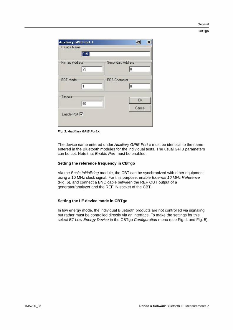
General
CBTgo
1MA200_3e Rohde amp Schwarz Bluetooth LE Measurements 7
Fig 3 Auxiliary GPIB Port x
The device name entered under Auxiliary GPIB Port x must be identical to the name entered in the Bluetooth modules for the individual tests The usual GPIB parameters can be set Note that Enable Port must be enabled
Setting the reference frequency in CBTgo
Via the Basic Initializing module the CBT can be synchronized with other equipment
using a 10 MHz clock signal For this purpose enable External 10 MHz Reference
(Fig 6) and connect a BNC cable between the REF OUT output of a
generatoranalyzer and the REF IN socket of the CBT
Setting the LE device mode in CBTgo
In low energy mode the individual Bluetooth products are not controlled via signaling
but rather must be controlled directly via an interface To make the settings for this
select BT Low Energy Device in the CBTgo Configuration menu (see Fig 4 and Fig 5)
General
CBTgo
1MA200_3e Rohde amp Schwarz Bluetooth LE Measurements 8
Fig 4 Setting the LE device mode
Fig 5 Configuration CBT LE DUT interface
Measuring the attenuation values
To obtain correct results the attenuation between the CBT and the DUT must be measured and entered into the BT Call Setup module Likewise the attenuation between the DUT and the signal generator(s) andor the spectrum analyzer must be measured and entered into the appropriate module(s) Rohde amp Schwarz also offers the free-of-charge FreRes software which allows you to record the frequency response It is available under httpwwwrohde-schwarzcomappnote1MA09
General
CBTgo
1MA200_3e Rohde amp Schwarz Bluetooth LE Measurements 9
2222 Required Standard CBTgo Modules
For proper operation all new modules presented here require other CBTgo modules
For these basic modules detailed descriptions already exist (see [3]) therefore only
the main settings will be described in this document
Each test sequence requires the Basic Initializing and the BT Low Energy
Connection Setup modules
Basic Initializing must be the first module of every sequence Please enable the
Bluetooth Low Energy function group here
Fig 6 Basic Initializing module
The Bluetooth LE Connection Setup module is required at the start of each Bluetooth
low energy test sequence (after Basic Initializing) The main parameters for setting up
a connection to a Bluetooth low energy device are set in this module
Fig 7 Bluetooth low energy connection setup
Besides the attenuation parameters you can either set the Autoranging mode or enter
a maximum level manually
Stipulated Measurements
CI and Receiver Selectivity Performance (RCV-LECA03C)
1MA200_3e Rohde amp Schwarz Bluetooth LE Measurements 10
3 Stipulated Measurements
31 CI and Receiver Selectivity Performance
(RCV-LECA03C)
This test verifies the receiver performance of the DUT in presence of a Bluetooth
co-adjacent channel interferer within the Bluetooth band The result is obtained by
means of a packet error rate (PER) measurement
The wanted signal is transmitted on a single channel in non-hopping mode A
Bluetooth interferer is likewise generated on a single channel coupled in and the PER
is determined In the next step the Bluetooth interferer is generated on all channels
one after the other and the PER is measured for each interferer channel The
complete test sequence is repeated twice ie the PER measurement is performed with
the wanted signal on three channels in total (Fig 8)
Fig 8 CI performance For the three individual channels the packet error rate in the presence of a
Bluetooth interferer inside the Bluetooth band is measured The measurement is repeated after
shifting the interferer by 1 MHz
The Bluetooth test specification defines the following settings
DUT in direct RX mode
Hopping off (RX on single channel)
Three channels (0 19 39)
Test packets with 37 octet PRBS9 payload
Interferer GFSK (modulation index 05) with PRBS15 on all Bluetooth channels in
consecutive order
1500 packets
Wanted input level at EUT 67 dBm
For levels see Table 3
Stipulated Measurements
CI and Receiver Selectivity Performance (RCV-LECA03C)
1MA200_3e Rohde amp Schwarz Bluetooth LE Measurements 11
CI level settings
Interference signal frequency Interferer
level (abs)
CI level Wanted
signal (abs)
Co-channel
(f RX = f Interference )
ndash88 dBm 21 dB ndash67 dBm
Adjacent channel
(f Interference = f RX plusmn 1 MHz )
ndash82 dBm 15 dB ndash67 dBm
Adjacent channel
(f Interference = f RX plusmn 2 MHz )
ndash50 dBm ndash17 dB ndash67 dBm
Adjacent channel
(f Interference = f RX plusmn (3 + n) MHz )
ndash40 dBm ndash27 dB ndash67 dBm
Image frequency
(f Interference = f Image )
ndash58 dBm ndash9 dB ndash67 dBm
Adjacent channel to image frequency
(f Interference = f Image plusmn 1 MHz )
ndash52 dBm ndash15 dB ndash67 dBm
Table 3 CI and receiver selectivity test parameter settings [1]
Results
For all measurements the PER must be better than 308 for a minimum of 1500
packets
For each of the three wanted channels the PER may exceed 308 for five
interferer frequencies spaced ge 2 MHz from the carrier and spaced ge 1 MHz from
the image frequency
For the interferer frequencies (max five) at which the PER limit is exceeded the
PER is measured in a second test run with a relaxed CI of 17 dB The PER limit
is again 308
Test setup
Fig 9 shows a typical test setup The CBT and the DUT are connected to each other
by a combiner via which the interference signal from a Bluetooth generator is coupled
in If the DUT transmits at high power levels an attenuator may be inserted to protect
the generator
Stipulated Measurements
CI and Receiver Selectivity Performance (RCV-LECA03C)
1MA200_3e Rohde amp Schwarz Bluetooth LE Measurements 12
Fig 9 Test setup for CI performance measurement
Measuring equipment and accessories
CBT tester SMx (SMU SMJ SMATE SMBV) signal generator
Resistive combiner up to 25 GHz (eg Weinschel 1515 1)
Attenuator up to 25 GHz (eg Suhner) The measurement is performed using the BT LE CI Performance module in CBTgo (Fig 10)
Stipulated Measurements
CI and Receiver Selectivity Performance (RCV-LECA03C)
1MA200_3e Rohde amp Schwarz Bluetooth LE Measurements 13
Fig 10 BT Low Energy CI Performance module in CBTgo
Under Test mode you can select the test packet payload type and the three RX
channels with different manufacturer-specific Image frequencies in Megahertz The
reference sensitivity is according to the specification ndash67 dBm (see Table 3)
Under Generator BT the auxiliary device name is to be entered The name must be
identical to that entered for Auxiliary GPIB Port x in the Configuration menu
Moreover the path loss between the generator and the DUT can be entered
Under Measurements you can enter the PER limit and the number of packets If Early
Exit is enabled the measurement is exited if more then five spurious frequencies are
detected You can show all measurement values with enabling Show detailed Values
The different levels are set automatically for measurements on the image-frequency
channel (see Table 3) The default settings comply with the test specification
CBTgo automatically performs the test on the three channels with the selected
generator settings
Stipulated Measurements
CI and Receiver Selectivity Performance (RCV-LECA03C)
1MA200_3e Rohde amp Schwarz Bluetooth LE Measurements 14
In the first test run all frequencies with a PER above the set limit are determined and
displayed In the second test run which is also performed automatically the DUTs
performance at these frequencies is retested with a CI of 17 dB This only takes
place for a maximum of five interference frequencies that are not
Co-channel
Adjacent channel plusmn 1 MHz
Image frequency
Adjacent channel to image frequency
With the settings in compliance with the test specification the measurement time is at
least four minutes (approx 1 second per PER measurement times 79 interferer channels times
three wanted channels)
Fig 11 shows a typical CI performance test report
Fig 11 CI performance test reports CBTgo shows the measurement results at the detected
spurious frequencies and a summary The repeated measurements with relaxed conditions is also
shown
Stipulated Measurements
Blocking Performance (RCV-LECA04C)
1MA200_3e Rohde amp Schwarz Bluetooth LE Measurements 15
32 Blocking Performance (RCV-LECA04C)
This measurement determines the receiver quality of the DUT if a continuous-wave
(CW) interferer is present outside the Bluetooth band The result is obtained by means
of a packet error rate (PER) measurement
The wanted signal is transmitted on a single channel in non-hopping mode A CW
interferer is likewise generated on a single channel coupled in and the BER is
determined In the next step the CW interferer is generated at intervals in consecutive
order over a specific frequency range and the PER is determined for each interferer
frequency (Fig 12)
Fig 12 Blocking performance For one channel the packet error rate in the presence of a CW
interferer outside the Bluetooth band is measured The measurement is repeated after shifting the
interferer by the frequency resolution
The Bluetooth test specification defines the following settings
DUT in direct RX mode
Hopping off (RX on single channel)
One channel (19)
Test packets with 37 octet PRBS9 payload
Interferer CW signal for levels and frequency ranges see Table 4
1500 packets
Wanted input level at EUT 67 dBm
Stipulated Measurements
Blocking Performance (RCV-LECA04C)
1MA200_3e Rohde amp Schwarz Bluetooth LE Measurements 16
Blocking level settings
Interference signal frequency Wanted
signal level
Blocking
signal level
Frequency
resolution
30 MHz to 2000 MHz ndash67 dBm ndash30 dBm 10 MHz
2003 MHz to 2399 MHz ndash67 dBm ndash35 dBm 3 MHz
2484 MHz to 2997 MHz ndash67 dBm ndash35 dBm 3 MHz
3000 MHz to 1275 GHz ndash67 dBm ndash30 dBm 25 MHz
Table 4 Blocking performance parameters first test run
Results
1st test run At each interferer frequency 1500 packets are measured The
frequencies at which a PER gt 308 is obtained are recorded The number of
frequencies recorded here must not exceed ten
2nd test run At each frequency recorded during the 1st test run 1500 packets are
measured at reduced interferer levels of ndash50 dBm The frequencies at which a
PER gt 308 is obtained are again recorded The PER limit may be exceeded for
a maximum of three frequencies
Test setup
Fig 13 shows a typical test setup The CBT and the DUT are connected to each other
by a combiner via which the interference signal from a CW generator is coupled in If
the DUT transmits at high power levels an attenuator may be inserted to protect the
generator
Fig 13 Test setup for blocking performance measurement
Stipulated Measurements
Blocking Performance (RCV-LECA04C)
1MA200_3e Rohde amp Schwarz Bluetooth LE Measurements 17
Measuring equipment and accessories
CBT tester SMx (SMF SMB SMR) generator up to 1275 GHz
Resistive combiner up to 1275 GHz (eg Weinschel 1515 1)
Attenuator up to 1275 GHz (eg Suhner) The measurement is performed using the BT Low Energy Blocking Performance module in CBTgo (Fig 14)
Fig 14 CBTgo BT Low Energy Blocking Performance module
Stipulated Measurements
Blocking Performance (RCV-LECA04C)
1MA200_3e Rohde amp Schwarz Bluetooth LE Measurements 18
Under Test mode you can select the test packet payload type The RX frequency of the measurement channel can be set The reference sensitivity level can be modified as required According to the specification this must be ndash67 dBm Under Generator CW the auxiliary device name is to be entered The name must be identical to that entered for Auxiliary GPIB Port x in the Configuration menu Moreover the path loss between the generator and the DUT can be set Under Blocking performance parameters the generator level as well as a start and a stop frequency can be entered in four columns In addition you can enter the measurement frequency resolution The default settings are the four ranges according to the specification (see Table 4) Under Measurements you can enter the PER limit the number of packets and the allowed exceptions for the two runs separately If Early Exit is enabled the measurement is exited if more then ten spurious frequencies are detected CBTgo automatically performs the test using the selected generator settings With the settings in compliance with the test specification the measurement time is at least 15 minutes (1 s per PER measurement times approx 890 interferer channels in the 1st test run) Fig 15 shows a typical entry in the test report
Stipulated Measurements
Blocking Performance (RCV-LECA04C)
1MA200_3e Rohde amp Schwarz Bluetooth LE Measurements 19
Fig 15 Blocking performance test report CBTgo shows the measurement results at the detected
spurious frequencies and a summary for the different sections The repeated measurements with
relaxed conditions are also shown
Stipulated Measurements
Intermodulation Performance (RCV-LECA05C)
1MA200_3e Rohde amp Schwarz Bluetooth LE Measurements 20
33 Intermodulation Performance (RCV-LECA05C)
This measurement verifies the intermodulation performance of the DUTs receiver A
PER measurement is performed using two interferers that cause intermodulation at the
DUTs receive frequency
The wanted signal is transmitted on a single channel in non-hopping mode A CW
interferer spaced +n MHz and a Bluetooth interferer spaced +2n MHz from the wanted
signal are generated coupled in and the PER is determined The measurement is
then performed with the interferers at ndashn MHz and ndash2n MHz The two measurements
are repeated on two more wanted channels (Fig 16)
Fig 16 Intermodulation performance For each of three channels the packet error rate in the
presence of a CW interferer in a distance n and in the presence of a Bluetooth interferer in a distance
2n is measured
The Bluetooth test specification defines the following settings
Hopping off (RX on single channel)
Three channels (0 19 39)
PRBS9
Wanted signal level at ndash64 dBm
n = 3 4 or 5 (defined by manufacturer)
Bluetooth interferer low energy GFSK with PRBS15 spaced plusmn2n MHz from wanted
signal level ndash50 dBm
CW interferer spaced plusmnn MHz from wanted signal level ndash50 dBm
1500 packets
Result
A PER of 308 must be obtained for each of the three channels
Stipulated Measurements
Intermodulation Performance (RCV-LECA05C)
1MA200_3e Rohde amp Schwarz Bluetooth LE Measurements 21
Test setup
The two interferer signals required in this measurement are supplied via two generator
paths that are combined via a hybrid combiner The resulting signal is coupled into the
line connecting the CBT and the DUT via a second hybrid combiner If a dual-channel
SMU is used one generator is sufficient (Fig 17) otherwise two generators are
required (Fig 18)
Fig 17 Test setup 1 for intermodulation performance measurement using one generator
Stipulated Measurements
Intermodulation Performance (RCV-LECA05C)
1MA200_3e Rohde amp Schwarz Bluetooth LE Measurements 22
Fig 18 Test setup 2 for intermodulation performance using two generators
Measuring equipment and accessories
CBT tester SMU or SMJ + SMF or SMB or SMR signal generators
Two hybrid combiners (eg Minicircuits ZFSC 2 2500)
The measurement is performed using the BT Low Energy Intermodulation
Performance module in CBTgo (Fig 19)
Stipulated Measurements
Intermodulation Performance (RCV-LECA05C)
1MA200_3e Rohde amp Schwarz Bluetooth LE Measurements 23
Fig 19 CBTgo BT Low Energy Intermodulation Performance module
Under Test Mode you can select the test packet payload type The RX frequencies of the three channels can be set The reference sensitivity level can be modified as required According to the specification this must be ndash 64 dBm
Under Generator 1 and Generator 2 the auxiliary device name is to be entered The
name must be identical to that entered for Auxiliary GPIB Port x in the Configuration
menu The intermodulation distance n (spacing from wanted signal) must be selected
Moreover the path loss between the generator and the DUT as well as the
interference level can be entered for each generator A second generator can be
included in the test setup if the first generator does not offer dual-channel capability
Stipulated Measurements
Intermodulation Performance (RCV-LECA05C)
1MA200_3e Rohde amp Schwarz Bluetooth LE Measurements 24
Under Measurements you can enter the PER limit and the number of packets The
default settings comply with the test specification
CBTgo automatically performs the test on the three channels using the selected
generator settings
Fig 20 shows a typical entry in the test report
Fig 20 Low energy intermodulation performance test report
Appendix
References
1MA200_3e Rohde amp Schwarz Bluetooth LE Measurements 25
4 Appendix
41 References
[1] Bluetooth Test amp Interoperability Working Group Bluetooth Low Energy RF PHY
Test Specification RF-PHYTS402 122012 Bluetooth SIG Inc
[2] Rohde amp Schwarz Manual for Windows Application CBTgo (V170)
[3] Rohde amp Schwarz Measurements on Bluetooth Products using
RampS CMU200CBT and CMUgoCBTgo Application Note 1CM50 102006
[4] Rohde amp Schwarz Bluetooth Measurements Using CBTgo Additional Tests Application Note 1MA106 022013
42 Additional Information
Please send your comments and suggestions regarding this application note to
TM-Applicationsrohde-schwarzcom
Visit the CBTgo website at
httpwww2rohde-
schwarzcomenproductstest_and_measurementmobile_radioCBT_CBT32-|-
Tools-|-67-|-1459html
or as a registered user in GLORIS the CMU Customer Web at
httpsextranetrohde-schwarzcom
Appendix
Ordering Information
1MA200_3e Rohde amp Schwarz Bluetooth LE Measurements 26
43 Ordering Information
Ordering information
Bluetooth tester
CBT Bluetooth tester with display 1153900035
CBT32 Bluetooth tester without display 1153900032
CBT-K57 Bluetooth Low Energy 1170410202
Vector signal generator
SMU200A Vector Signal Generator 1141200502
SMU-B9 Baseband Generator 128 Msample 1161076602
SMU-B10 Baseband Generator 64 Msample 1141700702
SMU-B11 Baseband Generator 16 Msample 1159841102
SMU-B13 Baseband Main Module 1141800304
SMU-B10x RF Path A
SMU-B20x RF Path B
SMW200A Vector Signal Generator 1412000002
SMW-B10 Baseband Generator with ARB
(64 Msample) and Digital Modulation
(realtime) 120 MHz RF bandwidth
1413120002
SMW-B13 Baseband Main Module one IQ path to RF 1413280702
SMW-B10x RF Path A
SMW-B20x RF Path B
SMBV100A Vector Signal Generator 1407600402
Signal generator
SMF100A Microwave Signal Generator
up to 435 GHz
1167000002
SMB100A RF and Microwave Signal Generator
up to 1275 GHz
1406600002
xx stands for the different frequency ranges (eg 1155500126 MHz to 26 GHz
Note Available options are not listed in detail
Please contact your local Rohde amp Schwarz sales office for further assistance
About Rohde amp Schwarz
Rohde amp Schwarz is an independent group
of companies specializing in electronics It is
a leading supplier of solutions in the fields of
test and measurement broadcasting
radiomonitoring and radiolocation as well as
secure communications Established more
than 75 years ago Rohde amp Schwarz has a
global presence and a dedicated service
network in over 70 countries Company
headquarters are in Munich Germany
Environmental commitment
Energy-efficient products
Continuous improvement in
environmental sustainability
ISO 14001-certified environmental
management system
Regional contact
Europe Africa Middle East
+49 89 4129 12345
customersupportrohde-schwarzcom North America
1-888-TEST-RSA (1-888-837-8772)
customersupportrsarohde-schwarzcom Latin America
+1-410-910-7988
customersupportlarohde-schwarzcom AsiaPacific
+65 65 13 04 88
customersupportasiarohde-schwarzcom
This application note and the supplied
programs may only be used subject to the
conditions of use set forth in the download
area of the Rohde amp Schwarz website
RampSreg is a registered trademark of Rohde amp Schwarz GmbH amp Co KG Trade names are trademarks of the owners
Rohde amp Schwarz GmbH amp Co KG
Muumlhldorfstraszlige 15 | D - 81671 Muumlnchen
Phone + 49 89 4129 - 0 | Fax + 49 89 4129 ndash 13777
wwwrohde-schwarzcom
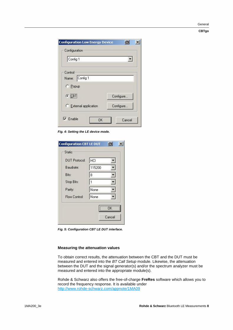
General
CBTgo
1MA200_3e Rohde amp Schwarz Bluetooth LE Measurements 8
Fig 4 Setting the LE device mode
Fig 5 Configuration CBT LE DUT interface
Measuring the attenuation values
To obtain correct results the attenuation between the CBT and the DUT must be measured and entered into the BT Call Setup module Likewise the attenuation between the DUT and the signal generator(s) andor the spectrum analyzer must be measured and entered into the appropriate module(s) Rohde amp Schwarz also offers the free-of-charge FreRes software which allows you to record the frequency response It is available under httpwwwrohde-schwarzcomappnote1MA09
General
CBTgo
1MA200_3e Rohde amp Schwarz Bluetooth LE Measurements 9
2222 Required Standard CBTgo Modules
For proper operation all new modules presented here require other CBTgo modules
For these basic modules detailed descriptions already exist (see [3]) therefore only
the main settings will be described in this document
Each test sequence requires the Basic Initializing and the BT Low Energy
Connection Setup modules
Basic Initializing must be the first module of every sequence Please enable the
Bluetooth Low Energy function group here
Fig 6 Basic Initializing module
The Bluetooth LE Connection Setup module is required at the start of each Bluetooth
low energy test sequence (after Basic Initializing) The main parameters for setting up
a connection to a Bluetooth low energy device are set in this module
Fig 7 Bluetooth low energy connection setup
Besides the attenuation parameters you can either set the Autoranging mode or enter
a maximum level manually
Stipulated Measurements
CI and Receiver Selectivity Performance (RCV-LECA03C)
1MA200_3e Rohde amp Schwarz Bluetooth LE Measurements 10
3 Stipulated Measurements
31 CI and Receiver Selectivity Performance
(RCV-LECA03C)
This test verifies the receiver performance of the DUT in presence of a Bluetooth
co-adjacent channel interferer within the Bluetooth band The result is obtained by
means of a packet error rate (PER) measurement
The wanted signal is transmitted on a single channel in non-hopping mode A
Bluetooth interferer is likewise generated on a single channel coupled in and the PER
is determined In the next step the Bluetooth interferer is generated on all channels
one after the other and the PER is measured for each interferer channel The
complete test sequence is repeated twice ie the PER measurement is performed with
the wanted signal on three channels in total (Fig 8)
Fig 8 CI performance For the three individual channels the packet error rate in the presence of a
Bluetooth interferer inside the Bluetooth band is measured The measurement is repeated after
shifting the interferer by 1 MHz
The Bluetooth test specification defines the following settings
DUT in direct RX mode
Hopping off (RX on single channel)
Three channels (0 19 39)
Test packets with 37 octet PRBS9 payload
Interferer GFSK (modulation index 05) with PRBS15 on all Bluetooth channels in
consecutive order
1500 packets
Wanted input level at EUT 67 dBm
For levels see Table 3
Stipulated Measurements
CI and Receiver Selectivity Performance (RCV-LECA03C)
1MA200_3e Rohde amp Schwarz Bluetooth LE Measurements 11
CI level settings
Interference signal frequency Interferer
level (abs)
CI level Wanted
signal (abs)
Co-channel
(f RX = f Interference )
ndash88 dBm 21 dB ndash67 dBm
Adjacent channel
(f Interference = f RX plusmn 1 MHz )
ndash82 dBm 15 dB ndash67 dBm
Adjacent channel
(f Interference = f RX plusmn 2 MHz )
ndash50 dBm ndash17 dB ndash67 dBm
Adjacent channel
(f Interference = f RX plusmn (3 + n) MHz )
ndash40 dBm ndash27 dB ndash67 dBm
Image frequency
(f Interference = f Image )
ndash58 dBm ndash9 dB ndash67 dBm
Adjacent channel to image frequency
(f Interference = f Image plusmn 1 MHz )
ndash52 dBm ndash15 dB ndash67 dBm
Table 3 CI and receiver selectivity test parameter settings [1]
Results
For all measurements the PER must be better than 308 for a minimum of 1500
packets
For each of the three wanted channels the PER may exceed 308 for five
interferer frequencies spaced ge 2 MHz from the carrier and spaced ge 1 MHz from
the image frequency
For the interferer frequencies (max five) at which the PER limit is exceeded the
PER is measured in a second test run with a relaxed CI of 17 dB The PER limit
is again 308
Test setup
Fig 9 shows a typical test setup The CBT and the DUT are connected to each other
by a combiner via which the interference signal from a Bluetooth generator is coupled
in If the DUT transmits at high power levels an attenuator may be inserted to protect
the generator
Stipulated Measurements
CI and Receiver Selectivity Performance (RCV-LECA03C)
1MA200_3e Rohde amp Schwarz Bluetooth LE Measurements 12
Fig 9 Test setup for CI performance measurement
Measuring equipment and accessories
CBT tester SMx (SMU SMJ SMATE SMBV) signal generator
Resistive combiner up to 25 GHz (eg Weinschel 1515 1)
Attenuator up to 25 GHz (eg Suhner) The measurement is performed using the BT LE CI Performance module in CBTgo (Fig 10)
Stipulated Measurements
CI and Receiver Selectivity Performance (RCV-LECA03C)
1MA200_3e Rohde amp Schwarz Bluetooth LE Measurements 13
Fig 10 BT Low Energy CI Performance module in CBTgo
Under Test mode you can select the test packet payload type and the three RX
channels with different manufacturer-specific Image frequencies in Megahertz The
reference sensitivity is according to the specification ndash67 dBm (see Table 3)
Under Generator BT the auxiliary device name is to be entered The name must be
identical to that entered for Auxiliary GPIB Port x in the Configuration menu
Moreover the path loss between the generator and the DUT can be entered
Under Measurements you can enter the PER limit and the number of packets If Early
Exit is enabled the measurement is exited if more then five spurious frequencies are
detected You can show all measurement values with enabling Show detailed Values
The different levels are set automatically for measurements on the image-frequency
channel (see Table 3) The default settings comply with the test specification
CBTgo automatically performs the test on the three channels with the selected
generator settings
Stipulated Measurements
CI and Receiver Selectivity Performance (RCV-LECA03C)
1MA200_3e Rohde amp Schwarz Bluetooth LE Measurements 14
In the first test run all frequencies with a PER above the set limit are determined and
displayed In the second test run which is also performed automatically the DUTs
performance at these frequencies is retested with a CI of 17 dB This only takes
place for a maximum of five interference frequencies that are not
Co-channel
Adjacent channel plusmn 1 MHz
Image frequency
Adjacent channel to image frequency
With the settings in compliance with the test specification the measurement time is at
least four minutes (approx 1 second per PER measurement times 79 interferer channels times
three wanted channels)
Fig 11 shows a typical CI performance test report
Fig 11 CI performance test reports CBTgo shows the measurement results at the detected
spurious frequencies and a summary The repeated measurements with relaxed conditions is also
shown
Stipulated Measurements
Blocking Performance (RCV-LECA04C)
1MA200_3e Rohde amp Schwarz Bluetooth LE Measurements 15
32 Blocking Performance (RCV-LECA04C)
This measurement determines the receiver quality of the DUT if a continuous-wave
(CW) interferer is present outside the Bluetooth band The result is obtained by means
of a packet error rate (PER) measurement
The wanted signal is transmitted on a single channel in non-hopping mode A CW
interferer is likewise generated on a single channel coupled in and the BER is
determined In the next step the CW interferer is generated at intervals in consecutive
order over a specific frequency range and the PER is determined for each interferer
frequency (Fig 12)
Fig 12 Blocking performance For one channel the packet error rate in the presence of a CW
interferer outside the Bluetooth band is measured The measurement is repeated after shifting the
interferer by the frequency resolution
The Bluetooth test specification defines the following settings
DUT in direct RX mode
Hopping off (RX on single channel)
One channel (19)
Test packets with 37 octet PRBS9 payload
Interferer CW signal for levels and frequency ranges see Table 4
1500 packets
Wanted input level at EUT 67 dBm
Stipulated Measurements
Blocking Performance (RCV-LECA04C)
1MA200_3e Rohde amp Schwarz Bluetooth LE Measurements 16
Blocking level settings
Interference signal frequency Wanted
signal level
Blocking
signal level
Frequency
resolution
30 MHz to 2000 MHz ndash67 dBm ndash30 dBm 10 MHz
2003 MHz to 2399 MHz ndash67 dBm ndash35 dBm 3 MHz
2484 MHz to 2997 MHz ndash67 dBm ndash35 dBm 3 MHz
3000 MHz to 1275 GHz ndash67 dBm ndash30 dBm 25 MHz
Table 4 Blocking performance parameters first test run
Results
1st test run At each interferer frequency 1500 packets are measured The
frequencies at which a PER gt 308 is obtained are recorded The number of
frequencies recorded here must not exceed ten
2nd test run At each frequency recorded during the 1st test run 1500 packets are
measured at reduced interferer levels of ndash50 dBm The frequencies at which a
PER gt 308 is obtained are again recorded The PER limit may be exceeded for
a maximum of three frequencies
Test setup
Fig 13 shows a typical test setup The CBT and the DUT are connected to each other
by a combiner via which the interference signal from a CW generator is coupled in If
the DUT transmits at high power levels an attenuator may be inserted to protect the
generator
Fig 13 Test setup for blocking performance measurement
Stipulated Measurements
Blocking Performance (RCV-LECA04C)
1MA200_3e Rohde amp Schwarz Bluetooth LE Measurements 17
Measuring equipment and accessories
CBT tester SMx (SMF SMB SMR) generator up to 1275 GHz
Resistive combiner up to 1275 GHz (eg Weinschel 1515 1)
Attenuator up to 1275 GHz (eg Suhner) The measurement is performed using the BT Low Energy Blocking Performance module in CBTgo (Fig 14)
Fig 14 CBTgo BT Low Energy Blocking Performance module
Stipulated Measurements
Blocking Performance (RCV-LECA04C)
1MA200_3e Rohde amp Schwarz Bluetooth LE Measurements 18
Under Test mode you can select the test packet payload type The RX frequency of the measurement channel can be set The reference sensitivity level can be modified as required According to the specification this must be ndash67 dBm Under Generator CW the auxiliary device name is to be entered The name must be identical to that entered for Auxiliary GPIB Port x in the Configuration menu Moreover the path loss between the generator and the DUT can be set Under Blocking performance parameters the generator level as well as a start and a stop frequency can be entered in four columns In addition you can enter the measurement frequency resolution The default settings are the four ranges according to the specification (see Table 4) Under Measurements you can enter the PER limit the number of packets and the allowed exceptions for the two runs separately If Early Exit is enabled the measurement is exited if more then ten spurious frequencies are detected CBTgo automatically performs the test using the selected generator settings With the settings in compliance with the test specification the measurement time is at least 15 minutes (1 s per PER measurement times approx 890 interferer channels in the 1st test run) Fig 15 shows a typical entry in the test report
Stipulated Measurements
Blocking Performance (RCV-LECA04C)
1MA200_3e Rohde amp Schwarz Bluetooth LE Measurements 19
Fig 15 Blocking performance test report CBTgo shows the measurement results at the detected
spurious frequencies and a summary for the different sections The repeated measurements with
relaxed conditions are also shown
Stipulated Measurements
Intermodulation Performance (RCV-LECA05C)
1MA200_3e Rohde amp Schwarz Bluetooth LE Measurements 20
33 Intermodulation Performance (RCV-LECA05C)
This measurement verifies the intermodulation performance of the DUTs receiver A
PER measurement is performed using two interferers that cause intermodulation at the
DUTs receive frequency
The wanted signal is transmitted on a single channel in non-hopping mode A CW
interferer spaced +n MHz and a Bluetooth interferer spaced +2n MHz from the wanted
signal are generated coupled in and the PER is determined The measurement is
then performed with the interferers at ndashn MHz and ndash2n MHz The two measurements
are repeated on two more wanted channels (Fig 16)
Fig 16 Intermodulation performance For each of three channels the packet error rate in the
presence of a CW interferer in a distance n and in the presence of a Bluetooth interferer in a distance
2n is measured
The Bluetooth test specification defines the following settings
Hopping off (RX on single channel)
Three channels (0 19 39)
PRBS9
Wanted signal level at ndash64 dBm
n = 3 4 or 5 (defined by manufacturer)
Bluetooth interferer low energy GFSK with PRBS15 spaced plusmn2n MHz from wanted
signal level ndash50 dBm
CW interferer spaced plusmnn MHz from wanted signal level ndash50 dBm
1500 packets
Result
A PER of 308 must be obtained for each of the three channels
Stipulated Measurements
Intermodulation Performance (RCV-LECA05C)
1MA200_3e Rohde amp Schwarz Bluetooth LE Measurements 21
Test setup
The two interferer signals required in this measurement are supplied via two generator
paths that are combined via a hybrid combiner The resulting signal is coupled into the
line connecting the CBT and the DUT via a second hybrid combiner If a dual-channel
SMU is used one generator is sufficient (Fig 17) otherwise two generators are
required (Fig 18)
Fig 17 Test setup 1 for intermodulation performance measurement using one generator
Stipulated Measurements
Intermodulation Performance (RCV-LECA05C)
1MA200_3e Rohde amp Schwarz Bluetooth LE Measurements 22
Fig 18 Test setup 2 for intermodulation performance using two generators
Measuring equipment and accessories
CBT tester SMU or SMJ + SMF or SMB or SMR signal generators
Two hybrid combiners (eg Minicircuits ZFSC 2 2500)
The measurement is performed using the BT Low Energy Intermodulation
Performance module in CBTgo (Fig 19)
Stipulated Measurements
Intermodulation Performance (RCV-LECA05C)
1MA200_3e Rohde amp Schwarz Bluetooth LE Measurements 23
Fig 19 CBTgo BT Low Energy Intermodulation Performance module
Under Test Mode you can select the test packet payload type The RX frequencies of the three channels can be set The reference sensitivity level can be modified as required According to the specification this must be ndash 64 dBm
Under Generator 1 and Generator 2 the auxiliary device name is to be entered The
name must be identical to that entered for Auxiliary GPIB Port x in the Configuration
menu The intermodulation distance n (spacing from wanted signal) must be selected
Moreover the path loss between the generator and the DUT as well as the
interference level can be entered for each generator A second generator can be
included in the test setup if the first generator does not offer dual-channel capability
Stipulated Measurements
Intermodulation Performance (RCV-LECA05C)
1MA200_3e Rohde amp Schwarz Bluetooth LE Measurements 24
Under Measurements you can enter the PER limit and the number of packets The
default settings comply with the test specification
CBTgo automatically performs the test on the three channels using the selected
generator settings
Fig 20 shows a typical entry in the test report
Fig 20 Low energy intermodulation performance test report
Appendix
References
1MA200_3e Rohde amp Schwarz Bluetooth LE Measurements 25
4 Appendix
41 References
[1] Bluetooth Test amp Interoperability Working Group Bluetooth Low Energy RF PHY
Test Specification RF-PHYTS402 122012 Bluetooth SIG Inc
[2] Rohde amp Schwarz Manual for Windows Application CBTgo (V170)
[3] Rohde amp Schwarz Measurements on Bluetooth Products using
RampS CMU200CBT and CMUgoCBTgo Application Note 1CM50 102006
[4] Rohde amp Schwarz Bluetooth Measurements Using CBTgo Additional Tests Application Note 1MA106 022013
42 Additional Information
Please send your comments and suggestions regarding this application note to
TM-Applicationsrohde-schwarzcom
Visit the CBTgo website at
httpwww2rohde-
schwarzcomenproductstest_and_measurementmobile_radioCBT_CBT32-|-
Tools-|-67-|-1459html
or as a registered user in GLORIS the CMU Customer Web at
httpsextranetrohde-schwarzcom
Appendix
Ordering Information
1MA200_3e Rohde amp Schwarz Bluetooth LE Measurements 26
43 Ordering Information
Ordering information
Bluetooth tester
CBT Bluetooth tester with display 1153900035
CBT32 Bluetooth tester without display 1153900032
CBT-K57 Bluetooth Low Energy 1170410202
Vector signal generator
SMU200A Vector Signal Generator 1141200502
SMU-B9 Baseband Generator 128 Msample 1161076602
SMU-B10 Baseband Generator 64 Msample 1141700702
SMU-B11 Baseband Generator 16 Msample 1159841102
SMU-B13 Baseband Main Module 1141800304
SMU-B10x RF Path A
SMU-B20x RF Path B
SMW200A Vector Signal Generator 1412000002
SMW-B10 Baseband Generator with ARB
(64 Msample) and Digital Modulation
(realtime) 120 MHz RF bandwidth
1413120002
SMW-B13 Baseband Main Module one IQ path to RF 1413280702
SMW-B10x RF Path A
SMW-B20x RF Path B
SMBV100A Vector Signal Generator 1407600402
Signal generator
SMF100A Microwave Signal Generator
up to 435 GHz
1167000002
SMB100A RF and Microwave Signal Generator
up to 1275 GHz
1406600002
xx stands for the different frequency ranges (eg 1155500126 MHz to 26 GHz
Note Available options are not listed in detail
Please contact your local Rohde amp Schwarz sales office for further assistance
About Rohde amp Schwarz
Rohde amp Schwarz is an independent group
of companies specializing in electronics It is
a leading supplier of solutions in the fields of
test and measurement broadcasting
radiomonitoring and radiolocation as well as
secure communications Established more
than 75 years ago Rohde amp Schwarz has a
global presence and a dedicated service
network in over 70 countries Company
headquarters are in Munich Germany
Environmental commitment
Energy-efficient products
Continuous improvement in
environmental sustainability
ISO 14001-certified environmental
management system
Regional contact
Europe Africa Middle East
+49 89 4129 12345
customersupportrohde-schwarzcom North America
1-888-TEST-RSA (1-888-837-8772)
customersupportrsarohde-schwarzcom Latin America
+1-410-910-7988
customersupportlarohde-schwarzcom AsiaPacific
+65 65 13 04 88
customersupportasiarohde-schwarzcom
This application note and the supplied
programs may only be used subject to the
conditions of use set forth in the download
area of the Rohde amp Schwarz website
RampSreg is a registered trademark of Rohde amp Schwarz GmbH amp Co KG Trade names are trademarks of the owners
Rohde amp Schwarz GmbH amp Co KG
Muumlhldorfstraszlige 15 | D - 81671 Muumlnchen
Phone + 49 89 4129 - 0 | Fax + 49 89 4129 ndash 13777
wwwrohde-schwarzcom
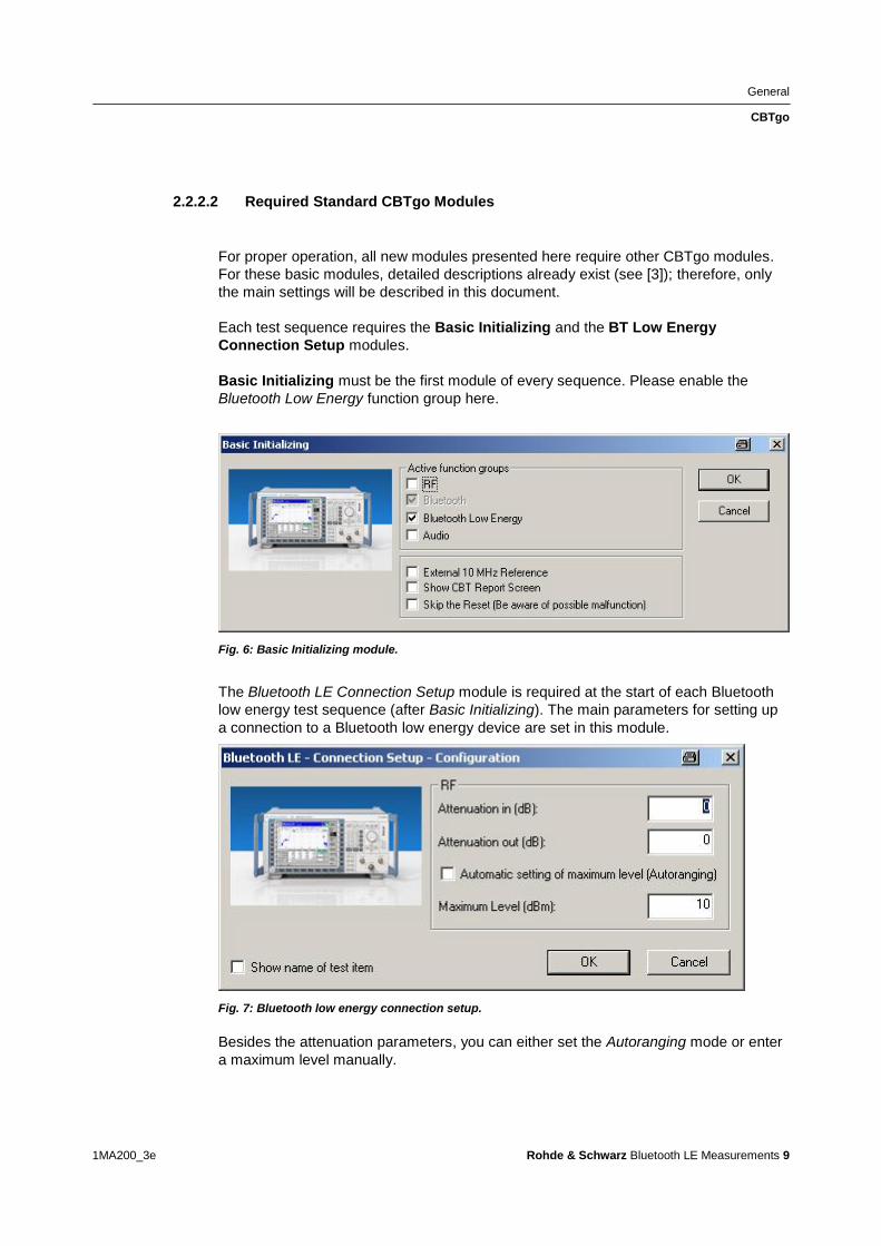
General
CBTgo
1MA200_3e Rohde amp Schwarz Bluetooth LE Measurements 9
2222 Required Standard CBTgo Modules
For proper operation all new modules presented here require other CBTgo modules
For these basic modules detailed descriptions already exist (see [3]) therefore only
the main settings will be described in this document
Each test sequence requires the Basic Initializing and the BT Low Energy
Connection Setup modules
Basic Initializing must be the first module of every sequence Please enable the
Bluetooth Low Energy function group here
Fig 6 Basic Initializing module
The Bluetooth LE Connection Setup module is required at the start of each Bluetooth
low energy test sequence (after Basic Initializing) The main parameters for setting up
a connection to a Bluetooth low energy device are set in this module
Fig 7 Bluetooth low energy connection setup
Besides the attenuation parameters you can either set the Autoranging mode or enter
a maximum level manually
Stipulated Measurements
CI and Receiver Selectivity Performance (RCV-LECA03C)
1MA200_3e Rohde amp Schwarz Bluetooth LE Measurements 10
3 Stipulated Measurements
31 CI and Receiver Selectivity Performance
(RCV-LECA03C)
This test verifies the receiver performance of the DUT in presence of a Bluetooth
co-adjacent channel interferer within the Bluetooth band The result is obtained by
means of a packet error rate (PER) measurement
The wanted signal is transmitted on a single channel in non-hopping mode A
Bluetooth interferer is likewise generated on a single channel coupled in and the PER
is determined In the next step the Bluetooth interferer is generated on all channels
one after the other and the PER is measured for each interferer channel The
complete test sequence is repeated twice ie the PER measurement is performed with
the wanted signal on three channels in total (Fig 8)
Fig 8 CI performance For the three individual channels the packet error rate in the presence of a
Bluetooth interferer inside the Bluetooth band is measured The measurement is repeated after
shifting the interferer by 1 MHz
The Bluetooth test specification defines the following settings
DUT in direct RX mode
Hopping off (RX on single channel)
Three channels (0 19 39)
Test packets with 37 octet PRBS9 payload
Interferer GFSK (modulation index 05) with PRBS15 on all Bluetooth channels in
consecutive order
1500 packets
Wanted input level at EUT 67 dBm
For levels see Table 3
Stipulated Measurements
CI and Receiver Selectivity Performance (RCV-LECA03C)
1MA200_3e Rohde amp Schwarz Bluetooth LE Measurements 11
CI level settings
Interference signal frequency Interferer
level (abs)
CI level Wanted
signal (abs)
Co-channel
(f RX = f Interference )
ndash88 dBm 21 dB ndash67 dBm
Adjacent channel
(f Interference = f RX plusmn 1 MHz )
ndash82 dBm 15 dB ndash67 dBm
Adjacent channel
(f Interference = f RX plusmn 2 MHz )
ndash50 dBm ndash17 dB ndash67 dBm
Adjacent channel
(f Interference = f RX plusmn (3 + n) MHz )
ndash40 dBm ndash27 dB ndash67 dBm
Image frequency
(f Interference = f Image )
ndash58 dBm ndash9 dB ndash67 dBm
Adjacent channel to image frequency
(f Interference = f Image plusmn 1 MHz )
ndash52 dBm ndash15 dB ndash67 dBm
Table 3 CI and receiver selectivity test parameter settings [1]
Results
For all measurements the PER must be better than 308 for a minimum of 1500
packets
For each of the three wanted channels the PER may exceed 308 for five
interferer frequencies spaced ge 2 MHz from the carrier and spaced ge 1 MHz from
the image frequency
For the interferer frequencies (max five) at which the PER limit is exceeded the
PER is measured in a second test run with a relaxed CI of 17 dB The PER limit
is again 308
Test setup
Fig 9 shows a typical test setup The CBT and the DUT are connected to each other
by a combiner via which the interference signal from a Bluetooth generator is coupled
in If the DUT transmits at high power levels an attenuator may be inserted to protect
the generator
Stipulated Measurements
CI and Receiver Selectivity Performance (RCV-LECA03C)
1MA200_3e Rohde amp Schwarz Bluetooth LE Measurements 12
Fig 9 Test setup for CI performance measurement
Measuring equipment and accessories
CBT tester SMx (SMU SMJ SMATE SMBV) signal generator
Resistive combiner up to 25 GHz (eg Weinschel 1515 1)
Attenuator up to 25 GHz (eg Suhner) The measurement is performed using the BT LE CI Performance module in CBTgo (Fig 10)
Stipulated Measurements
CI and Receiver Selectivity Performance (RCV-LECA03C)
1MA200_3e Rohde amp Schwarz Bluetooth LE Measurements 13
Fig 10 BT Low Energy CI Performance module in CBTgo
Under Test mode you can select the test packet payload type and the three RX
channels with different manufacturer-specific Image frequencies in Megahertz The
reference sensitivity is according to the specification ndash67 dBm (see Table 3)
Under Generator BT the auxiliary device name is to be entered The name must be
identical to that entered for Auxiliary GPIB Port x in the Configuration menu
Moreover the path loss between the generator and the DUT can be entered
Under Measurements you can enter the PER limit and the number of packets If Early
Exit is enabled the measurement is exited if more then five spurious frequencies are
detected You can show all measurement values with enabling Show detailed Values
The different levels are set automatically for measurements on the image-frequency
channel (see Table 3) The default settings comply with the test specification
CBTgo automatically performs the test on the three channels with the selected
generator settings
Stipulated Measurements
CI and Receiver Selectivity Performance (RCV-LECA03C)
1MA200_3e Rohde amp Schwarz Bluetooth LE Measurements 14
In the first test run all frequencies with a PER above the set limit are determined and
displayed In the second test run which is also performed automatically the DUTs
performance at these frequencies is retested with a CI of 17 dB This only takes
place for a maximum of five interference frequencies that are not
Co-channel
Adjacent channel plusmn 1 MHz
Image frequency
Adjacent channel to image frequency
With the settings in compliance with the test specification the measurement time is at
least four minutes (approx 1 second per PER measurement times 79 interferer channels times
three wanted channels)
Fig 11 shows a typical CI performance test report
Fig 11 CI performance test reports CBTgo shows the measurement results at the detected
spurious frequencies and a summary The repeated measurements with relaxed conditions is also
shown
Stipulated Measurements
Blocking Performance (RCV-LECA04C)
1MA200_3e Rohde amp Schwarz Bluetooth LE Measurements 15
32 Blocking Performance (RCV-LECA04C)
This measurement determines the receiver quality of the DUT if a continuous-wave
(CW) interferer is present outside the Bluetooth band The result is obtained by means
of a packet error rate (PER) measurement
The wanted signal is transmitted on a single channel in non-hopping mode A CW
interferer is likewise generated on a single channel coupled in and the BER is
determined In the next step the CW interferer is generated at intervals in consecutive
order over a specific frequency range and the PER is determined for each interferer
frequency (Fig 12)
Fig 12 Blocking performance For one channel the packet error rate in the presence of a CW
interferer outside the Bluetooth band is measured The measurement is repeated after shifting the
interferer by the frequency resolution
The Bluetooth test specification defines the following settings
DUT in direct RX mode
Hopping off (RX on single channel)
One channel (19)
Test packets with 37 octet PRBS9 payload
Interferer CW signal for levels and frequency ranges see Table 4
1500 packets
Wanted input level at EUT 67 dBm
Stipulated Measurements
Blocking Performance (RCV-LECA04C)
1MA200_3e Rohde amp Schwarz Bluetooth LE Measurements 16
Blocking level settings
Interference signal frequency Wanted
signal level
Blocking
signal level
Frequency
resolution
30 MHz to 2000 MHz ndash67 dBm ndash30 dBm 10 MHz
2003 MHz to 2399 MHz ndash67 dBm ndash35 dBm 3 MHz
2484 MHz to 2997 MHz ndash67 dBm ndash35 dBm 3 MHz
3000 MHz to 1275 GHz ndash67 dBm ndash30 dBm 25 MHz
Table 4 Blocking performance parameters first test run
Results
1st test run At each interferer frequency 1500 packets are measured The
frequencies at which a PER gt 308 is obtained are recorded The number of
frequencies recorded here must not exceed ten
2nd test run At each frequency recorded during the 1st test run 1500 packets are
measured at reduced interferer levels of ndash50 dBm The frequencies at which a
PER gt 308 is obtained are again recorded The PER limit may be exceeded for
a maximum of three frequencies
Test setup
Fig 13 shows a typical test setup The CBT and the DUT are connected to each other
by a combiner via which the interference signal from a CW generator is coupled in If
the DUT transmits at high power levels an attenuator may be inserted to protect the
generator
Fig 13 Test setup for blocking performance measurement
Stipulated Measurements
Blocking Performance (RCV-LECA04C)
1MA200_3e Rohde amp Schwarz Bluetooth LE Measurements 17
Measuring equipment and accessories
CBT tester SMx (SMF SMB SMR) generator up to 1275 GHz
Resistive combiner up to 1275 GHz (eg Weinschel 1515 1)
Attenuator up to 1275 GHz (eg Suhner) The measurement is performed using the BT Low Energy Blocking Performance module in CBTgo (Fig 14)
Fig 14 CBTgo BT Low Energy Blocking Performance module
Stipulated Measurements
Blocking Performance (RCV-LECA04C)
1MA200_3e Rohde amp Schwarz Bluetooth LE Measurements 18
Under Test mode you can select the test packet payload type The RX frequency of the measurement channel can be set The reference sensitivity level can be modified as required According to the specification this must be ndash67 dBm Under Generator CW the auxiliary device name is to be entered The name must be identical to that entered for Auxiliary GPIB Port x in the Configuration menu Moreover the path loss between the generator and the DUT can be set Under Blocking performance parameters the generator level as well as a start and a stop frequency can be entered in four columns In addition you can enter the measurement frequency resolution The default settings are the four ranges according to the specification (see Table 4) Under Measurements you can enter the PER limit the number of packets and the allowed exceptions for the two runs separately If Early Exit is enabled the measurement is exited if more then ten spurious frequencies are detected CBTgo automatically performs the test using the selected generator settings With the settings in compliance with the test specification the measurement time is at least 15 minutes (1 s per PER measurement times approx 890 interferer channels in the 1st test run) Fig 15 shows a typical entry in the test report
Stipulated Measurements
Blocking Performance (RCV-LECA04C)
1MA200_3e Rohde amp Schwarz Bluetooth LE Measurements 19
Fig 15 Blocking performance test report CBTgo shows the measurement results at the detected
spurious frequencies and a summary for the different sections The repeated measurements with
relaxed conditions are also shown
Stipulated Measurements
Intermodulation Performance (RCV-LECA05C)
1MA200_3e Rohde amp Schwarz Bluetooth LE Measurements 20
33 Intermodulation Performance (RCV-LECA05C)
This measurement verifies the intermodulation performance of the DUTs receiver A
PER measurement is performed using two interferers that cause intermodulation at the
DUTs receive frequency
The wanted signal is transmitted on a single channel in non-hopping mode A CW
interferer spaced +n MHz and a Bluetooth interferer spaced +2n MHz from the wanted
signal are generated coupled in and the PER is determined The measurement is
then performed with the interferers at ndashn MHz and ndash2n MHz The two measurements
are repeated on two more wanted channels (Fig 16)
Fig 16 Intermodulation performance For each of three channels the packet error rate in the
presence of a CW interferer in a distance n and in the presence of a Bluetooth interferer in a distance
2n is measured
The Bluetooth test specification defines the following settings
Hopping off (RX on single channel)
Three channels (0 19 39)
PRBS9
Wanted signal level at ndash64 dBm
n = 3 4 or 5 (defined by manufacturer)
Bluetooth interferer low energy GFSK with PRBS15 spaced plusmn2n MHz from wanted
signal level ndash50 dBm
CW interferer spaced plusmnn MHz from wanted signal level ndash50 dBm
1500 packets
Result
A PER of 308 must be obtained for each of the three channels
Stipulated Measurements
Intermodulation Performance (RCV-LECA05C)
1MA200_3e Rohde amp Schwarz Bluetooth LE Measurements 21
Test setup
The two interferer signals required in this measurement are supplied via two generator
paths that are combined via a hybrid combiner The resulting signal is coupled into the
line connecting the CBT and the DUT via a second hybrid combiner If a dual-channel
SMU is used one generator is sufficient (Fig 17) otherwise two generators are
required (Fig 18)
Fig 17 Test setup 1 for intermodulation performance measurement using one generator
Stipulated Measurements
Intermodulation Performance (RCV-LECA05C)
1MA200_3e Rohde amp Schwarz Bluetooth LE Measurements 22
Fig 18 Test setup 2 for intermodulation performance using two generators
Measuring equipment and accessories
CBT tester SMU or SMJ + SMF or SMB or SMR signal generators
Two hybrid combiners (eg Minicircuits ZFSC 2 2500)
The measurement is performed using the BT Low Energy Intermodulation
Performance module in CBTgo (Fig 19)
Stipulated Measurements
Intermodulation Performance (RCV-LECA05C)
1MA200_3e Rohde amp Schwarz Bluetooth LE Measurements 23
Fig 19 CBTgo BT Low Energy Intermodulation Performance module
Under Test Mode you can select the test packet payload type The RX frequencies of the three channels can be set The reference sensitivity level can be modified as required According to the specification this must be ndash 64 dBm
Under Generator 1 and Generator 2 the auxiliary device name is to be entered The
name must be identical to that entered for Auxiliary GPIB Port x in the Configuration
menu The intermodulation distance n (spacing from wanted signal) must be selected
Moreover the path loss between the generator and the DUT as well as the
interference level can be entered for each generator A second generator can be
included in the test setup if the first generator does not offer dual-channel capability
Stipulated Measurements
Intermodulation Performance (RCV-LECA05C)
1MA200_3e Rohde amp Schwarz Bluetooth LE Measurements 24
Under Measurements you can enter the PER limit and the number of packets The
default settings comply with the test specification
CBTgo automatically performs the test on the three channels using the selected
generator settings
Fig 20 shows a typical entry in the test report
Fig 20 Low energy intermodulation performance test report
Appendix
References
1MA200_3e Rohde amp Schwarz Bluetooth LE Measurements 25
4 Appendix
41 References
[1] Bluetooth Test amp Interoperability Working Group Bluetooth Low Energy RF PHY
Test Specification RF-PHYTS402 122012 Bluetooth SIG Inc
[2] Rohde amp Schwarz Manual for Windows Application CBTgo (V170)
[3] Rohde amp Schwarz Measurements on Bluetooth Products using
RampS CMU200CBT and CMUgoCBTgo Application Note 1CM50 102006
[4] Rohde amp Schwarz Bluetooth Measurements Using CBTgo Additional Tests Application Note 1MA106 022013
42 Additional Information
Please send your comments and suggestions regarding this application note to
TM-Applicationsrohde-schwarzcom
Visit the CBTgo website at
httpwww2rohde-
schwarzcomenproductstest_and_measurementmobile_radioCBT_CBT32-|-
Tools-|-67-|-1459html
or as a registered user in GLORIS the CMU Customer Web at
httpsextranetrohde-schwarzcom
Appendix
Ordering Information
1MA200_3e Rohde amp Schwarz Bluetooth LE Measurements 26
43 Ordering Information
Ordering information
Bluetooth tester
CBT Bluetooth tester with display 1153900035
CBT32 Bluetooth tester without display 1153900032
CBT-K57 Bluetooth Low Energy 1170410202
Vector signal generator
SMU200A Vector Signal Generator 1141200502
SMU-B9 Baseband Generator 128 Msample 1161076602
SMU-B10 Baseband Generator 64 Msample 1141700702
SMU-B11 Baseband Generator 16 Msample 1159841102
SMU-B13 Baseband Main Module 1141800304
SMU-B10x RF Path A
SMU-B20x RF Path B
SMW200A Vector Signal Generator 1412000002
SMW-B10 Baseband Generator with ARB
(64 Msample) and Digital Modulation
(realtime) 120 MHz RF bandwidth
1413120002
SMW-B13 Baseband Main Module one IQ path to RF 1413280702
SMW-B10x RF Path A
SMW-B20x RF Path B
SMBV100A Vector Signal Generator 1407600402
Signal generator
SMF100A Microwave Signal Generator
up to 435 GHz
1167000002
SMB100A RF and Microwave Signal Generator
up to 1275 GHz
1406600002
xx stands for the different frequency ranges (eg 1155500126 MHz to 26 GHz
Note Available options are not listed in detail
Please contact your local Rohde amp Schwarz sales office for further assistance
About Rohde amp Schwarz
Rohde amp Schwarz is an independent group
of companies specializing in electronics It is
a leading supplier of solutions in the fields of
test and measurement broadcasting
radiomonitoring and radiolocation as well as
secure communications Established more
than 75 years ago Rohde amp Schwarz has a
global presence and a dedicated service
network in over 70 countries Company
headquarters are in Munich Germany
Environmental commitment
Energy-efficient products
Continuous improvement in
environmental sustainability
ISO 14001-certified environmental
management system
Regional contact
Europe Africa Middle East
+49 89 4129 12345
customersupportrohde-schwarzcom North America
1-888-TEST-RSA (1-888-837-8772)
customersupportrsarohde-schwarzcom Latin America
+1-410-910-7988
customersupportlarohde-schwarzcom AsiaPacific
+65 65 13 04 88
customersupportasiarohde-schwarzcom
This application note and the supplied
programs may only be used subject to the
conditions of use set forth in the download
area of the Rohde amp Schwarz website
RampSreg is a registered trademark of Rohde amp Schwarz GmbH amp Co KG Trade names are trademarks of the owners
Rohde amp Schwarz GmbH amp Co KG
Muumlhldorfstraszlige 15 | D - 81671 Muumlnchen
Phone + 49 89 4129 - 0 | Fax + 49 89 4129 ndash 13777
wwwrohde-schwarzcom
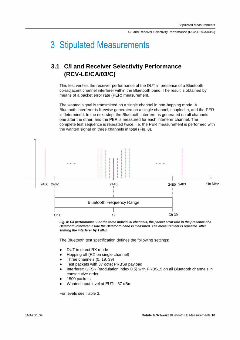
Stipulated Measurements
CI and Receiver Selectivity Performance (RCV-LECA03C)
1MA200_3e Rohde amp Schwarz Bluetooth LE Measurements 10
3 Stipulated Measurements
31 CI and Receiver Selectivity Performance
(RCV-LECA03C)
This test verifies the receiver performance of the DUT in presence of a Bluetooth
co-adjacent channel interferer within the Bluetooth band The result is obtained by
means of a packet error rate (PER) measurement
The wanted signal is transmitted on a single channel in non-hopping mode A
Bluetooth interferer is likewise generated on a single channel coupled in and the PER
is determined In the next step the Bluetooth interferer is generated on all channels
one after the other and the PER is measured for each interferer channel The
complete test sequence is repeated twice ie the PER measurement is performed with
the wanted signal on three channels in total (Fig 8)
Fig 8 CI performance For the three individual channels the packet error rate in the presence of a
Bluetooth interferer inside the Bluetooth band is measured The measurement is repeated after
shifting the interferer by 1 MHz
The Bluetooth test specification defines the following settings
DUT in direct RX mode
Hopping off (RX on single channel)
Three channels (0 19 39)
Test packets with 37 octet PRBS9 payload
Interferer GFSK (modulation index 05) with PRBS15 on all Bluetooth channels in
consecutive order
1500 packets
Wanted input level at EUT 67 dBm
For levels see Table 3
Stipulated Measurements
CI and Receiver Selectivity Performance (RCV-LECA03C)
1MA200_3e Rohde amp Schwarz Bluetooth LE Measurements 11
CI level settings
Interference signal frequency Interferer
level (abs)
CI level Wanted
signal (abs)
Co-channel
(f RX = f Interference )
ndash88 dBm 21 dB ndash67 dBm
Adjacent channel
(f Interference = f RX plusmn 1 MHz )
ndash82 dBm 15 dB ndash67 dBm
Adjacent channel
(f Interference = f RX plusmn 2 MHz )
ndash50 dBm ndash17 dB ndash67 dBm
Adjacent channel
(f Interference = f RX plusmn (3 + n) MHz )
ndash40 dBm ndash27 dB ndash67 dBm
Image frequency
(f Interference = f Image )
ndash58 dBm ndash9 dB ndash67 dBm
Adjacent channel to image frequency
(f Interference = f Image plusmn 1 MHz )
ndash52 dBm ndash15 dB ndash67 dBm
Table 3 CI and receiver selectivity test parameter settings [1]
Results
For all measurements the PER must be better than 308 for a minimum of 1500
packets
For each of the three wanted channels the PER may exceed 308 for five
interferer frequencies spaced ge 2 MHz from the carrier and spaced ge 1 MHz from
the image frequency
For the interferer frequencies (max five) at which the PER limit is exceeded the
PER is measured in a second test run with a relaxed CI of 17 dB The PER limit
is again 308
Test setup
Fig 9 shows a typical test setup The CBT and the DUT are connected to each other
by a combiner via which the interference signal from a Bluetooth generator is coupled
in If the DUT transmits at high power levels an attenuator may be inserted to protect
the generator
Stipulated Measurements
CI and Receiver Selectivity Performance (RCV-LECA03C)
1MA200_3e Rohde amp Schwarz Bluetooth LE Measurements 12
Fig 9 Test setup for CI performance measurement
Measuring equipment and accessories
CBT tester SMx (SMU SMJ SMATE SMBV) signal generator
Resistive combiner up to 25 GHz (eg Weinschel 1515 1)
Attenuator up to 25 GHz (eg Suhner) The measurement is performed using the BT LE CI Performance module in CBTgo (Fig 10)
Stipulated Measurements
CI and Receiver Selectivity Performance (RCV-LECA03C)
1MA200_3e Rohde amp Schwarz Bluetooth LE Measurements 13
Fig 10 BT Low Energy CI Performance module in CBTgo
Under Test mode you can select the test packet payload type and the three RX
channels with different manufacturer-specific Image frequencies in Megahertz The
reference sensitivity is according to the specification ndash67 dBm (see Table 3)
Under Generator BT the auxiliary device name is to be entered The name must be
identical to that entered for Auxiliary GPIB Port x in the Configuration menu
Moreover the path loss between the generator and the DUT can be entered
Under Measurements you can enter the PER limit and the number of packets If Early
Exit is enabled the measurement is exited if more then five spurious frequencies are
detected You can show all measurement values with enabling Show detailed Values
The different levels are set automatically for measurements on the image-frequency
channel (see Table 3) The default settings comply with the test specification
CBTgo automatically performs the test on the three channels with the selected
generator settings
Stipulated Measurements
CI and Receiver Selectivity Performance (RCV-LECA03C)
1MA200_3e Rohde amp Schwarz Bluetooth LE Measurements 14
In the first test run all frequencies with a PER above the set limit are determined and
displayed In the second test run which is also performed automatically the DUTs
performance at these frequencies is retested with a CI of 17 dB This only takes
place for a maximum of five interference frequencies that are not
Co-channel
Adjacent channel plusmn 1 MHz
Image frequency
Adjacent channel to image frequency
With the settings in compliance with the test specification the measurement time is at
least four minutes (approx 1 second per PER measurement times 79 interferer channels times
three wanted channels)
Fig 11 shows a typical CI performance test report
Fig 11 CI performance test reports CBTgo shows the measurement results at the detected
spurious frequencies and a summary The repeated measurements with relaxed conditions is also
shown
Stipulated Measurements
Blocking Performance (RCV-LECA04C)
1MA200_3e Rohde amp Schwarz Bluetooth LE Measurements 15
32 Blocking Performance (RCV-LECA04C)
This measurement determines the receiver quality of the DUT if a continuous-wave
(CW) interferer is present outside the Bluetooth band The result is obtained by means
of a packet error rate (PER) measurement
The wanted signal is transmitted on a single channel in non-hopping mode A CW
interferer is likewise generated on a single channel coupled in and the BER is
determined In the next step the CW interferer is generated at intervals in consecutive
order over a specific frequency range and the PER is determined for each interferer
frequency (Fig 12)
Fig 12 Blocking performance For one channel the packet error rate in the presence of a CW
interferer outside the Bluetooth band is measured The measurement is repeated after shifting the
interferer by the frequency resolution
The Bluetooth test specification defines the following settings
DUT in direct RX mode
Hopping off (RX on single channel)
One channel (19)
Test packets with 37 octet PRBS9 payload
Interferer CW signal for levels and frequency ranges see Table 4
1500 packets
Wanted input level at EUT 67 dBm
Stipulated Measurements
Blocking Performance (RCV-LECA04C)
1MA200_3e Rohde amp Schwarz Bluetooth LE Measurements 16
Blocking level settings
Interference signal frequency Wanted
signal level
Blocking
signal level
Frequency
resolution
30 MHz to 2000 MHz ndash67 dBm ndash30 dBm 10 MHz
2003 MHz to 2399 MHz ndash67 dBm ndash35 dBm 3 MHz
2484 MHz to 2997 MHz ndash67 dBm ndash35 dBm 3 MHz
3000 MHz to 1275 GHz ndash67 dBm ndash30 dBm 25 MHz
Table 4 Blocking performance parameters first test run
Results
1st test run At each interferer frequency 1500 packets are measured The
frequencies at which a PER gt 308 is obtained are recorded The number of
frequencies recorded here must not exceed ten
2nd test run At each frequency recorded during the 1st test run 1500 packets are
measured at reduced interferer levels of ndash50 dBm The frequencies at which a
PER gt 308 is obtained are again recorded The PER limit may be exceeded for
a maximum of three frequencies
Test setup
Fig 13 shows a typical test setup The CBT and the DUT are connected to each other
by a combiner via which the interference signal from a CW generator is coupled in If
the DUT transmits at high power levels an attenuator may be inserted to protect the
generator
Fig 13 Test setup for blocking performance measurement
Stipulated Measurements
Blocking Performance (RCV-LECA04C)
1MA200_3e Rohde amp Schwarz Bluetooth LE Measurements 17
Measuring equipment and accessories
CBT tester SMx (SMF SMB SMR) generator up to 1275 GHz
Resistive combiner up to 1275 GHz (eg Weinschel 1515 1)
Attenuator up to 1275 GHz (eg Suhner) The measurement is performed using the BT Low Energy Blocking Performance module in CBTgo (Fig 14)
Fig 14 CBTgo BT Low Energy Blocking Performance module
Stipulated Measurements
Blocking Performance (RCV-LECA04C)
1MA200_3e Rohde amp Schwarz Bluetooth LE Measurements 18
Under Test mode you can select the test packet payload type The RX frequency of the measurement channel can be set The reference sensitivity level can be modified as required According to the specification this must be ndash67 dBm Under Generator CW the auxiliary device name is to be entered The name must be identical to that entered for Auxiliary GPIB Port x in the Configuration menu Moreover the path loss between the generator and the DUT can be set Under Blocking performance parameters the generator level as well as a start and a stop frequency can be entered in four columns In addition you can enter the measurement frequency resolution The default settings are the four ranges according to the specification (see Table 4) Under Measurements you can enter the PER limit the number of packets and the allowed exceptions for the two runs separately If Early Exit is enabled the measurement is exited if more then ten spurious frequencies are detected CBTgo automatically performs the test using the selected generator settings With the settings in compliance with the test specification the measurement time is at least 15 minutes (1 s per PER measurement times approx 890 interferer channels in the 1st test run) Fig 15 shows a typical entry in the test report
Stipulated Measurements
Blocking Performance (RCV-LECA04C)
1MA200_3e Rohde amp Schwarz Bluetooth LE Measurements 19
Fig 15 Blocking performance test report CBTgo shows the measurement results at the detected
spurious frequencies and a summary for the different sections The repeated measurements with
relaxed conditions are also shown
Stipulated Measurements
Intermodulation Performance (RCV-LECA05C)
1MA200_3e Rohde amp Schwarz Bluetooth LE Measurements 20
33 Intermodulation Performance (RCV-LECA05C)
This measurement verifies the intermodulation performance of the DUTs receiver A
PER measurement is performed using two interferers that cause intermodulation at the
DUTs receive frequency
The wanted signal is transmitted on a single channel in non-hopping mode A CW
interferer spaced +n MHz and a Bluetooth interferer spaced +2n MHz from the wanted
signal are generated coupled in and the PER is determined The measurement is
then performed with the interferers at ndashn MHz and ndash2n MHz The two measurements
are repeated on two more wanted channels (Fig 16)
Fig 16 Intermodulation performance For each of three channels the packet error rate in the
presence of a CW interferer in a distance n and in the presence of a Bluetooth interferer in a distance
2n is measured
The Bluetooth test specification defines the following settings
Hopping off (RX on single channel)
Three channels (0 19 39)
PRBS9
Wanted signal level at ndash64 dBm
n = 3 4 or 5 (defined by manufacturer)
Bluetooth interferer low energy GFSK with PRBS15 spaced plusmn2n MHz from wanted
signal level ndash50 dBm
CW interferer spaced plusmnn MHz from wanted signal level ndash50 dBm
1500 packets
Result
A PER of 308 must be obtained for each of the three channels
Stipulated Measurements
Intermodulation Performance (RCV-LECA05C)
1MA200_3e Rohde amp Schwarz Bluetooth LE Measurements 21
Test setup
The two interferer signals required in this measurement are supplied via two generator
paths that are combined via a hybrid combiner The resulting signal is coupled into the
line connecting the CBT and the DUT via a second hybrid combiner If a dual-channel
SMU is used one generator is sufficient (Fig 17) otherwise two generators are
required (Fig 18)
Fig 17 Test setup 1 for intermodulation performance measurement using one generator
Stipulated Measurements
Intermodulation Performance (RCV-LECA05C)
1MA200_3e Rohde amp Schwarz Bluetooth LE Measurements 22
Fig 18 Test setup 2 for intermodulation performance using two generators
Measuring equipment and accessories
CBT tester SMU or SMJ + SMF or SMB or SMR signal generators
Two hybrid combiners (eg Minicircuits ZFSC 2 2500)
The measurement is performed using the BT Low Energy Intermodulation
Performance module in CBTgo (Fig 19)
Stipulated Measurements
Intermodulation Performance (RCV-LECA05C)
1MA200_3e Rohde amp Schwarz Bluetooth LE Measurements 23
Fig 19 CBTgo BT Low Energy Intermodulation Performance module
Under Test Mode you can select the test packet payload type The RX frequencies of the three channels can be set The reference sensitivity level can be modified as required According to the specification this must be ndash 64 dBm
Under Generator 1 and Generator 2 the auxiliary device name is to be entered The
name must be identical to that entered for Auxiliary GPIB Port x in the Configuration
menu The intermodulation distance n (spacing from wanted signal) must be selected
Moreover the path loss between the generator and the DUT as well as the
interference level can be entered for each generator A second generator can be
included in the test setup if the first generator does not offer dual-channel capability
Stipulated Measurements
Intermodulation Performance (RCV-LECA05C)
1MA200_3e Rohde amp Schwarz Bluetooth LE Measurements 24
Under Measurements you can enter the PER limit and the number of packets The
default settings comply with the test specification
CBTgo automatically performs the test on the three channels using the selected
generator settings
Fig 20 shows a typical entry in the test report
Fig 20 Low energy intermodulation performance test report
Appendix
References
1MA200_3e Rohde amp Schwarz Bluetooth LE Measurements 25
4 Appendix
41 References
[1] Bluetooth Test amp Interoperability Working Group Bluetooth Low Energy RF PHY
Test Specification RF-PHYTS402 122012 Bluetooth SIG Inc
[2] Rohde amp Schwarz Manual for Windows Application CBTgo (V170)
[3] Rohde amp Schwarz Measurements on Bluetooth Products using
RampS CMU200CBT and CMUgoCBTgo Application Note 1CM50 102006
[4] Rohde amp Schwarz Bluetooth Measurements Using CBTgo Additional Tests Application Note 1MA106 022013
42 Additional Information
Please send your comments and suggestions regarding this application note to
TM-Applicationsrohde-schwarzcom
Visit the CBTgo website at
httpwww2rohde-
schwarzcomenproductstest_and_measurementmobile_radioCBT_CBT32-|-
Tools-|-67-|-1459html
or as a registered user in GLORIS the CMU Customer Web at
httpsextranetrohde-schwarzcom
Appendix
Ordering Information
1MA200_3e Rohde amp Schwarz Bluetooth LE Measurements 26
43 Ordering Information
Ordering information
Bluetooth tester
CBT Bluetooth tester with display 1153900035
CBT32 Bluetooth tester without display 1153900032
CBT-K57 Bluetooth Low Energy 1170410202
Vector signal generator
SMU200A Vector Signal Generator 1141200502
SMU-B9 Baseband Generator 128 Msample 1161076602
SMU-B10 Baseband Generator 64 Msample 1141700702
SMU-B11 Baseband Generator 16 Msample 1159841102
SMU-B13 Baseband Main Module 1141800304
SMU-B10x RF Path A
SMU-B20x RF Path B
SMW200A Vector Signal Generator 1412000002
SMW-B10 Baseband Generator with ARB
(64 Msample) and Digital Modulation
(realtime) 120 MHz RF bandwidth
1413120002
SMW-B13 Baseband Main Module one IQ path to RF 1413280702
SMW-B10x RF Path A
SMW-B20x RF Path B
SMBV100A Vector Signal Generator 1407600402
Signal generator
SMF100A Microwave Signal Generator
up to 435 GHz
1167000002
SMB100A RF and Microwave Signal Generator
up to 1275 GHz
1406600002
xx stands for the different frequency ranges (eg 1155500126 MHz to 26 GHz
Note Available options are not listed in detail
Please contact your local Rohde amp Schwarz sales office for further assistance
About Rohde amp Schwarz
Rohde amp Schwarz is an independent group
of companies specializing in electronics It is
a leading supplier of solutions in the fields of
test and measurement broadcasting
radiomonitoring and radiolocation as well as
secure communications Established more
than 75 years ago Rohde amp Schwarz has a
global presence and a dedicated service
network in over 70 countries Company
headquarters are in Munich Germany
Environmental commitment
Energy-efficient products
Continuous improvement in
environmental sustainability
ISO 14001-certified environmental
management system
Regional contact
Europe Africa Middle East
+49 89 4129 12345
customersupportrohde-schwarzcom North America
1-888-TEST-RSA (1-888-837-8772)
customersupportrsarohde-schwarzcom Latin America
+1-410-910-7988
customersupportlarohde-schwarzcom AsiaPacific
+65 65 13 04 88
customersupportasiarohde-schwarzcom
This application note and the supplied
programs may only be used subject to the
conditions of use set forth in the download
area of the Rohde amp Schwarz website
RampSreg is a registered trademark of Rohde amp Schwarz GmbH amp Co KG Trade names are trademarks of the owners
Rohde amp Schwarz GmbH amp Co KG
Muumlhldorfstraszlige 15 | D - 81671 Muumlnchen
Phone + 49 89 4129 - 0 | Fax + 49 89 4129 ndash 13777
wwwrohde-schwarzcom
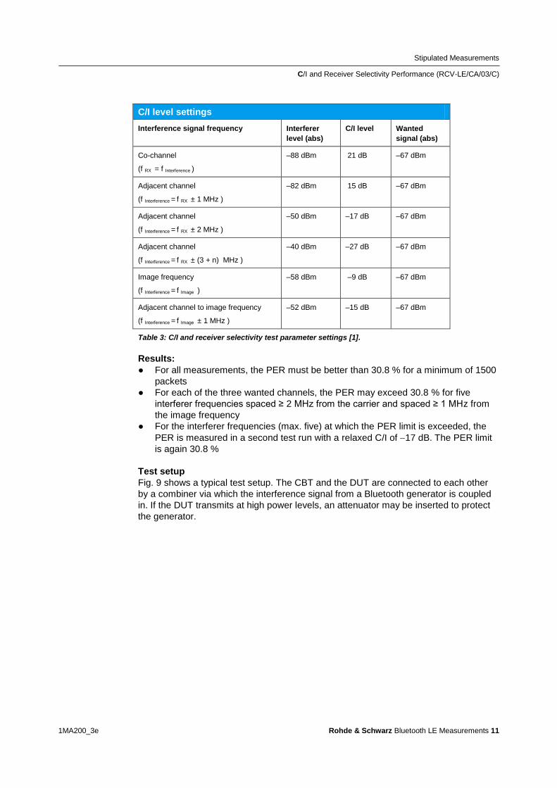
Stipulated Measurements
CI and Receiver Selectivity Performance (RCV-LECA03C)
1MA200_3e Rohde amp Schwarz Bluetooth LE Measurements 11
CI level settings
Interference signal frequency Interferer
level (abs)
CI level Wanted
signal (abs)
Co-channel
(f RX = f Interference )
ndash88 dBm 21 dB ndash67 dBm
Adjacent channel
(f Interference = f RX plusmn 1 MHz )
ndash82 dBm 15 dB ndash67 dBm
Adjacent channel
(f Interference = f RX plusmn 2 MHz )
ndash50 dBm ndash17 dB ndash67 dBm
Adjacent channel
(f Interference = f RX plusmn (3 + n) MHz )
ndash40 dBm ndash27 dB ndash67 dBm
Image frequency
(f Interference = f Image )
ndash58 dBm ndash9 dB ndash67 dBm
Adjacent channel to image frequency
(f Interference = f Image plusmn 1 MHz )
ndash52 dBm ndash15 dB ndash67 dBm
Table 3 CI and receiver selectivity test parameter settings [1]
Results
For all measurements the PER must be better than 308 for a minimum of 1500
packets
For each of the three wanted channels the PER may exceed 308 for five
interferer frequencies spaced ge 2 MHz from the carrier and spaced ge 1 MHz from
the image frequency
For the interferer frequencies (max five) at which the PER limit is exceeded the
PER is measured in a second test run with a relaxed CI of 17 dB The PER limit
is again 308
Test setup
Fig 9 shows a typical test setup The CBT and the DUT are connected to each other
by a combiner via which the interference signal from a Bluetooth generator is coupled
in If the DUT transmits at high power levels an attenuator may be inserted to protect
the generator
Stipulated Measurements
CI and Receiver Selectivity Performance (RCV-LECA03C)
1MA200_3e Rohde amp Schwarz Bluetooth LE Measurements 12
Fig 9 Test setup for CI performance measurement
Measuring equipment and accessories
CBT tester SMx (SMU SMJ SMATE SMBV) signal generator
Resistive combiner up to 25 GHz (eg Weinschel 1515 1)
Attenuator up to 25 GHz (eg Suhner) The measurement is performed using the BT LE CI Performance module in CBTgo (Fig 10)
Stipulated Measurements
CI and Receiver Selectivity Performance (RCV-LECA03C)
1MA200_3e Rohde amp Schwarz Bluetooth LE Measurements 13
Fig 10 BT Low Energy CI Performance module in CBTgo
Under Test mode you can select the test packet payload type and the three RX
channels with different manufacturer-specific Image frequencies in Megahertz The
reference sensitivity is according to the specification ndash67 dBm (see Table 3)
Under Generator BT the auxiliary device name is to be entered The name must be
identical to that entered for Auxiliary GPIB Port x in the Configuration menu
Moreover the path loss between the generator and the DUT can be entered
Under Measurements you can enter the PER limit and the number of packets If Early
Exit is enabled the measurement is exited if more then five spurious frequencies are
detected You can show all measurement values with enabling Show detailed Values
The different levels are set automatically for measurements on the image-frequency
channel (see Table 3) The default settings comply with the test specification
CBTgo automatically performs the test on the three channels with the selected
generator settings
Stipulated Measurements
CI and Receiver Selectivity Performance (RCV-LECA03C)
1MA200_3e Rohde amp Schwarz Bluetooth LE Measurements 14
In the first test run all frequencies with a PER above the set limit are determined and
displayed In the second test run which is also performed automatically the DUTs
performance at these frequencies is retested with a CI of 17 dB This only takes
place for a maximum of five interference frequencies that are not
Co-channel
Adjacent channel plusmn 1 MHz
Image frequency
Adjacent channel to image frequency
With the settings in compliance with the test specification the measurement time is at
least four minutes (approx 1 second per PER measurement times 79 interferer channels times
three wanted channels)
Fig 11 shows a typical CI performance test report
Fig 11 CI performance test reports CBTgo shows the measurement results at the detected
spurious frequencies and a summary The repeated measurements with relaxed conditions is also
shown
Stipulated Measurements
Blocking Performance (RCV-LECA04C)
1MA200_3e Rohde amp Schwarz Bluetooth LE Measurements 15
32 Blocking Performance (RCV-LECA04C)
This measurement determines the receiver quality of the DUT if a continuous-wave
(CW) interferer is present outside the Bluetooth band The result is obtained by means
of a packet error rate (PER) measurement
The wanted signal is transmitted on a single channel in non-hopping mode A CW
interferer is likewise generated on a single channel coupled in and the BER is
determined In the next step the CW interferer is generated at intervals in consecutive
order over a specific frequency range and the PER is determined for each interferer
frequency (Fig 12)
Fig 12 Blocking performance For one channel the packet error rate in the presence of a CW
interferer outside the Bluetooth band is measured The measurement is repeated after shifting the
interferer by the frequency resolution
The Bluetooth test specification defines the following settings
DUT in direct RX mode
Hopping off (RX on single channel)
One channel (19)
Test packets with 37 octet PRBS9 payload
Interferer CW signal for levels and frequency ranges see Table 4
1500 packets
Wanted input level at EUT 67 dBm
Stipulated Measurements
Blocking Performance (RCV-LECA04C)
1MA200_3e Rohde amp Schwarz Bluetooth LE Measurements 16
Blocking level settings
Interference signal frequency Wanted
signal level
Blocking
signal level
Frequency
resolution
30 MHz to 2000 MHz ndash67 dBm ndash30 dBm 10 MHz
2003 MHz to 2399 MHz ndash67 dBm ndash35 dBm 3 MHz
2484 MHz to 2997 MHz ndash67 dBm ndash35 dBm 3 MHz
3000 MHz to 1275 GHz ndash67 dBm ndash30 dBm 25 MHz
Table 4 Blocking performance parameters first test run
Results
1st test run At each interferer frequency 1500 packets are measured The
frequencies at which a PER gt 308 is obtained are recorded The number of
frequencies recorded here must not exceed ten
2nd test run At each frequency recorded during the 1st test run 1500 packets are
measured at reduced interferer levels of ndash50 dBm The frequencies at which a
PER gt 308 is obtained are again recorded The PER limit may be exceeded for
a maximum of three frequencies
Test setup
Fig 13 shows a typical test setup The CBT and the DUT are connected to each other
by a combiner via which the interference signal from a CW generator is coupled in If
the DUT transmits at high power levels an attenuator may be inserted to protect the
generator
Fig 13 Test setup for blocking performance measurement
Stipulated Measurements
Blocking Performance (RCV-LECA04C)
1MA200_3e Rohde amp Schwarz Bluetooth LE Measurements 17
Measuring equipment and accessories
CBT tester SMx (SMF SMB SMR) generator up to 1275 GHz
Resistive combiner up to 1275 GHz (eg Weinschel 1515 1)
Attenuator up to 1275 GHz (eg Suhner) The measurement is performed using the BT Low Energy Blocking Performance module in CBTgo (Fig 14)
Fig 14 CBTgo BT Low Energy Blocking Performance module
Stipulated Measurements
Blocking Performance (RCV-LECA04C)
1MA200_3e Rohde amp Schwarz Bluetooth LE Measurements 18
Under Test mode you can select the test packet payload type The RX frequency of the measurement channel can be set The reference sensitivity level can be modified as required According to the specification this must be ndash67 dBm Under Generator CW the auxiliary device name is to be entered The name must be identical to that entered for Auxiliary GPIB Port x in the Configuration menu Moreover the path loss between the generator and the DUT can be set Under Blocking performance parameters the generator level as well as a start and a stop frequency can be entered in four columns In addition you can enter the measurement frequency resolution The default settings are the four ranges according to the specification (see Table 4) Under Measurements you can enter the PER limit the number of packets and the allowed exceptions for the two runs separately If Early Exit is enabled the measurement is exited if more then ten spurious frequencies are detected CBTgo automatically performs the test using the selected generator settings With the settings in compliance with the test specification the measurement time is at least 15 minutes (1 s per PER measurement times approx 890 interferer channels in the 1st test run) Fig 15 shows a typical entry in the test report
Stipulated Measurements
Blocking Performance (RCV-LECA04C)
1MA200_3e Rohde amp Schwarz Bluetooth LE Measurements 19
Fig 15 Blocking performance test report CBTgo shows the measurement results at the detected
spurious frequencies and a summary for the different sections The repeated measurements with
relaxed conditions are also shown
Stipulated Measurements
Intermodulation Performance (RCV-LECA05C)
1MA200_3e Rohde amp Schwarz Bluetooth LE Measurements 20
33 Intermodulation Performance (RCV-LECA05C)
This measurement verifies the intermodulation performance of the DUTs receiver A
PER measurement is performed using two interferers that cause intermodulation at the
DUTs receive frequency
The wanted signal is transmitted on a single channel in non-hopping mode A CW
interferer spaced +n MHz and a Bluetooth interferer spaced +2n MHz from the wanted
signal are generated coupled in and the PER is determined The measurement is
then performed with the interferers at ndashn MHz and ndash2n MHz The two measurements
are repeated on two more wanted channels (Fig 16)
Fig 16 Intermodulation performance For each of three channels the packet error rate in the
presence of a CW interferer in a distance n and in the presence of a Bluetooth interferer in a distance
2n is measured
The Bluetooth test specification defines the following settings
Hopping off (RX on single channel)
Three channels (0 19 39)
PRBS9
Wanted signal level at ndash64 dBm
n = 3 4 or 5 (defined by manufacturer)
Bluetooth interferer low energy GFSK with PRBS15 spaced plusmn2n MHz from wanted
signal level ndash50 dBm
CW interferer spaced plusmnn MHz from wanted signal level ndash50 dBm
1500 packets
Result
A PER of 308 must be obtained for each of the three channels
Stipulated Measurements
Intermodulation Performance (RCV-LECA05C)
1MA200_3e Rohde amp Schwarz Bluetooth LE Measurements 21
Test setup
The two interferer signals required in this measurement are supplied via two generator
paths that are combined via a hybrid combiner The resulting signal is coupled into the
line connecting the CBT and the DUT via a second hybrid combiner If a dual-channel
SMU is used one generator is sufficient (Fig 17) otherwise two generators are
required (Fig 18)
Fig 17 Test setup 1 for intermodulation performance measurement using one generator
Stipulated Measurements
Intermodulation Performance (RCV-LECA05C)
1MA200_3e Rohde amp Schwarz Bluetooth LE Measurements 22
Fig 18 Test setup 2 for intermodulation performance using two generators
Measuring equipment and accessories
CBT tester SMU or SMJ + SMF or SMB or SMR signal generators
Two hybrid combiners (eg Minicircuits ZFSC 2 2500)
The measurement is performed using the BT Low Energy Intermodulation
Performance module in CBTgo (Fig 19)
Stipulated Measurements
Intermodulation Performance (RCV-LECA05C)
1MA200_3e Rohde amp Schwarz Bluetooth LE Measurements 23
Fig 19 CBTgo BT Low Energy Intermodulation Performance module
Under Test Mode you can select the test packet payload type The RX frequencies of the three channels can be set The reference sensitivity level can be modified as required According to the specification this must be ndash 64 dBm
Under Generator 1 and Generator 2 the auxiliary device name is to be entered The
name must be identical to that entered for Auxiliary GPIB Port x in the Configuration
menu The intermodulation distance n (spacing from wanted signal) must be selected
Moreover the path loss between the generator and the DUT as well as the
interference level can be entered for each generator A second generator can be
included in the test setup if the first generator does not offer dual-channel capability
Stipulated Measurements
Intermodulation Performance (RCV-LECA05C)
1MA200_3e Rohde amp Schwarz Bluetooth LE Measurements 24
Under Measurements you can enter the PER limit and the number of packets The
default settings comply with the test specification
CBTgo automatically performs the test on the three channels using the selected
generator settings
Fig 20 shows a typical entry in the test report
Fig 20 Low energy intermodulation performance test report
Appendix
References
1MA200_3e Rohde amp Schwarz Bluetooth LE Measurements 25
4 Appendix
41 References
[1] Bluetooth Test amp Interoperability Working Group Bluetooth Low Energy RF PHY
Test Specification RF-PHYTS402 122012 Bluetooth SIG Inc
[2] Rohde amp Schwarz Manual for Windows Application CBTgo (V170)
[3] Rohde amp Schwarz Measurements on Bluetooth Products using
RampS CMU200CBT and CMUgoCBTgo Application Note 1CM50 102006
[4] Rohde amp Schwarz Bluetooth Measurements Using CBTgo Additional Tests Application Note 1MA106 022013
42 Additional Information
Please send your comments and suggestions regarding this application note to
TM-Applicationsrohde-schwarzcom
Visit the CBTgo website at
httpwww2rohde-
schwarzcomenproductstest_and_measurementmobile_radioCBT_CBT32-|-
Tools-|-67-|-1459html
or as a registered user in GLORIS the CMU Customer Web at
httpsextranetrohde-schwarzcom
Appendix
Ordering Information
1MA200_3e Rohde amp Schwarz Bluetooth LE Measurements 26
43 Ordering Information
Ordering information
Bluetooth tester
CBT Bluetooth tester with display 1153900035
CBT32 Bluetooth tester without display 1153900032
CBT-K57 Bluetooth Low Energy 1170410202
Vector signal generator
SMU200A Vector Signal Generator 1141200502
SMU-B9 Baseband Generator 128 Msample 1161076602
SMU-B10 Baseband Generator 64 Msample 1141700702
SMU-B11 Baseband Generator 16 Msample 1159841102
SMU-B13 Baseband Main Module 1141800304
SMU-B10x RF Path A
SMU-B20x RF Path B
SMW200A Vector Signal Generator 1412000002
SMW-B10 Baseband Generator with ARB
(64 Msample) and Digital Modulation
(realtime) 120 MHz RF bandwidth
1413120002
SMW-B13 Baseband Main Module one IQ path to RF 1413280702
SMW-B10x RF Path A
SMW-B20x RF Path B
SMBV100A Vector Signal Generator 1407600402
Signal generator
SMF100A Microwave Signal Generator
up to 435 GHz
1167000002
SMB100A RF and Microwave Signal Generator
up to 1275 GHz
1406600002
xx stands for the different frequency ranges (eg 1155500126 MHz to 26 GHz
Note Available options are not listed in detail
Please contact your local Rohde amp Schwarz sales office for further assistance
About Rohde amp Schwarz
Rohde amp Schwarz is an independent group
of companies specializing in electronics It is
a leading supplier of solutions in the fields of
test and measurement broadcasting
radiomonitoring and radiolocation as well as
secure communications Established more
than 75 years ago Rohde amp Schwarz has a
global presence and a dedicated service
network in over 70 countries Company
headquarters are in Munich Germany
Environmental commitment
Energy-efficient products
Continuous improvement in
environmental sustainability
ISO 14001-certified environmental
management system
Regional contact
Europe Africa Middle East
+49 89 4129 12345
customersupportrohde-schwarzcom North America
1-888-TEST-RSA (1-888-837-8772)
customersupportrsarohde-schwarzcom Latin America
+1-410-910-7988
customersupportlarohde-schwarzcom AsiaPacific
+65 65 13 04 88
customersupportasiarohde-schwarzcom
This application note and the supplied
programs may only be used subject to the
conditions of use set forth in the download
area of the Rohde amp Schwarz website
RampSreg is a registered trademark of Rohde amp Schwarz GmbH amp Co KG Trade names are trademarks of the owners
Rohde amp Schwarz GmbH amp Co KG
Muumlhldorfstraszlige 15 | D - 81671 Muumlnchen
Phone + 49 89 4129 - 0 | Fax + 49 89 4129 ndash 13777
wwwrohde-schwarzcom
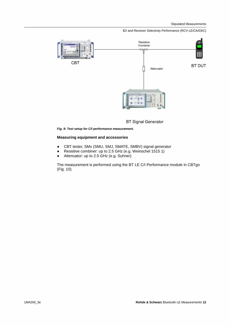
Stipulated Measurements
CI and Receiver Selectivity Performance (RCV-LECA03C)
1MA200_3e Rohde amp Schwarz Bluetooth LE Measurements 12
Fig 9 Test setup for CI performance measurement
Measuring equipment and accessories
CBT tester SMx (SMU SMJ SMATE SMBV) signal generator
Resistive combiner up to 25 GHz (eg Weinschel 1515 1)
Attenuator up to 25 GHz (eg Suhner) The measurement is performed using the BT LE CI Performance module in CBTgo (Fig 10)
Stipulated Measurements
CI and Receiver Selectivity Performance (RCV-LECA03C)
1MA200_3e Rohde amp Schwarz Bluetooth LE Measurements 13
Fig 10 BT Low Energy CI Performance module in CBTgo
Under Test mode you can select the test packet payload type and the three RX
channels with different manufacturer-specific Image frequencies in Megahertz The
reference sensitivity is according to the specification ndash67 dBm (see Table 3)
Under Generator BT the auxiliary device name is to be entered The name must be
identical to that entered for Auxiliary GPIB Port x in the Configuration menu
Moreover the path loss between the generator and the DUT can be entered
Under Measurements you can enter the PER limit and the number of packets If Early
Exit is enabled the measurement is exited if more then five spurious frequencies are
detected You can show all measurement values with enabling Show detailed Values
The different levels are set automatically for measurements on the image-frequency
channel (see Table 3) The default settings comply with the test specification
CBTgo automatically performs the test on the three channels with the selected
generator settings
Stipulated Measurements
CI and Receiver Selectivity Performance (RCV-LECA03C)
1MA200_3e Rohde amp Schwarz Bluetooth LE Measurements 14
In the first test run all frequencies with a PER above the set limit are determined and
displayed In the second test run which is also performed automatically the DUTs
performance at these frequencies is retested with a CI of 17 dB This only takes
place for a maximum of five interference frequencies that are not
Co-channel
Adjacent channel plusmn 1 MHz
Image frequency
Adjacent channel to image frequency
With the settings in compliance with the test specification the measurement time is at
least four minutes (approx 1 second per PER measurement times 79 interferer channels times
three wanted channels)
Fig 11 shows a typical CI performance test report
Fig 11 CI performance test reports CBTgo shows the measurement results at the detected
spurious frequencies and a summary The repeated measurements with relaxed conditions is also
shown
Stipulated Measurements
Blocking Performance (RCV-LECA04C)
1MA200_3e Rohde amp Schwarz Bluetooth LE Measurements 15
32 Blocking Performance (RCV-LECA04C)
This measurement determines the receiver quality of the DUT if a continuous-wave
(CW) interferer is present outside the Bluetooth band The result is obtained by means
of a packet error rate (PER) measurement
The wanted signal is transmitted on a single channel in non-hopping mode A CW
interferer is likewise generated on a single channel coupled in and the BER is
determined In the next step the CW interferer is generated at intervals in consecutive
order over a specific frequency range and the PER is determined for each interferer
frequency (Fig 12)
Fig 12 Blocking performance For one channel the packet error rate in the presence of a CW
interferer outside the Bluetooth band is measured The measurement is repeated after shifting the
interferer by the frequency resolution
The Bluetooth test specification defines the following settings
DUT in direct RX mode
Hopping off (RX on single channel)
One channel (19)
Test packets with 37 octet PRBS9 payload
Interferer CW signal for levels and frequency ranges see Table 4
1500 packets
Wanted input level at EUT 67 dBm
Stipulated Measurements
Blocking Performance (RCV-LECA04C)
1MA200_3e Rohde amp Schwarz Bluetooth LE Measurements 16
Blocking level settings
Interference signal frequency Wanted
signal level
Blocking
signal level
Frequency
resolution
30 MHz to 2000 MHz ndash67 dBm ndash30 dBm 10 MHz
2003 MHz to 2399 MHz ndash67 dBm ndash35 dBm 3 MHz
2484 MHz to 2997 MHz ndash67 dBm ndash35 dBm 3 MHz
3000 MHz to 1275 GHz ndash67 dBm ndash30 dBm 25 MHz
Table 4 Blocking performance parameters first test run
Results
1st test run At each interferer frequency 1500 packets are measured The
frequencies at which a PER gt 308 is obtained are recorded The number of
frequencies recorded here must not exceed ten
2nd test run At each frequency recorded during the 1st test run 1500 packets are
measured at reduced interferer levels of ndash50 dBm The frequencies at which a
PER gt 308 is obtained are again recorded The PER limit may be exceeded for
a maximum of three frequencies
Test setup
Fig 13 shows a typical test setup The CBT and the DUT are connected to each other
by a combiner via which the interference signal from a CW generator is coupled in If
the DUT transmits at high power levels an attenuator may be inserted to protect the
generator
Fig 13 Test setup for blocking performance measurement
Stipulated Measurements
Blocking Performance (RCV-LECA04C)
1MA200_3e Rohde amp Schwarz Bluetooth LE Measurements 17
Measuring equipment and accessories
CBT tester SMx (SMF SMB SMR) generator up to 1275 GHz
Resistive combiner up to 1275 GHz (eg Weinschel 1515 1)
Attenuator up to 1275 GHz (eg Suhner) The measurement is performed using the BT Low Energy Blocking Performance module in CBTgo (Fig 14)
Fig 14 CBTgo BT Low Energy Blocking Performance module
Stipulated Measurements
Blocking Performance (RCV-LECA04C)
1MA200_3e Rohde amp Schwarz Bluetooth LE Measurements 18
Under Test mode you can select the test packet payload type The RX frequency of the measurement channel can be set The reference sensitivity level can be modified as required According to the specification this must be ndash67 dBm Under Generator CW the auxiliary device name is to be entered The name must be identical to that entered for Auxiliary GPIB Port x in the Configuration menu Moreover the path loss between the generator and the DUT can be set Under Blocking performance parameters the generator level as well as a start and a stop frequency can be entered in four columns In addition you can enter the measurement frequency resolution The default settings are the four ranges according to the specification (see Table 4) Under Measurements you can enter the PER limit the number of packets and the allowed exceptions for the two runs separately If Early Exit is enabled the measurement is exited if more then ten spurious frequencies are detected CBTgo automatically performs the test using the selected generator settings With the settings in compliance with the test specification the measurement time is at least 15 minutes (1 s per PER measurement times approx 890 interferer channels in the 1st test run) Fig 15 shows a typical entry in the test report
Stipulated Measurements
Blocking Performance (RCV-LECA04C)
1MA200_3e Rohde amp Schwarz Bluetooth LE Measurements 19
Fig 15 Blocking performance test report CBTgo shows the measurement results at the detected
spurious frequencies and a summary for the different sections The repeated measurements with
relaxed conditions are also shown
Stipulated Measurements
Intermodulation Performance (RCV-LECA05C)
1MA200_3e Rohde amp Schwarz Bluetooth LE Measurements 20
33 Intermodulation Performance (RCV-LECA05C)
This measurement verifies the intermodulation performance of the DUTs receiver A
PER measurement is performed using two interferers that cause intermodulation at the
DUTs receive frequency
The wanted signal is transmitted on a single channel in non-hopping mode A CW
interferer spaced +n MHz and a Bluetooth interferer spaced +2n MHz from the wanted
signal are generated coupled in and the PER is determined The measurement is
then performed with the interferers at ndashn MHz and ndash2n MHz The two measurements
are repeated on two more wanted channels (Fig 16)
Fig 16 Intermodulation performance For each of three channels the packet error rate in the
presence of a CW interferer in a distance n and in the presence of a Bluetooth interferer in a distance
2n is measured
The Bluetooth test specification defines the following settings
Hopping off (RX on single channel)
Three channels (0 19 39)
PRBS9
Wanted signal level at ndash64 dBm
n = 3 4 or 5 (defined by manufacturer)
Bluetooth interferer low energy GFSK with PRBS15 spaced plusmn2n MHz from wanted
signal level ndash50 dBm
CW interferer spaced plusmnn MHz from wanted signal level ndash50 dBm
1500 packets
Result
A PER of 308 must be obtained for each of the three channels
Stipulated Measurements
Intermodulation Performance (RCV-LECA05C)
1MA200_3e Rohde amp Schwarz Bluetooth LE Measurements 21
Test setup
The two interferer signals required in this measurement are supplied via two generator
paths that are combined via a hybrid combiner The resulting signal is coupled into the
line connecting the CBT and the DUT via a second hybrid combiner If a dual-channel
SMU is used one generator is sufficient (Fig 17) otherwise two generators are
required (Fig 18)
Fig 17 Test setup 1 for intermodulation performance measurement using one generator
Stipulated Measurements
Intermodulation Performance (RCV-LECA05C)
1MA200_3e Rohde amp Schwarz Bluetooth LE Measurements 22
Fig 18 Test setup 2 for intermodulation performance using two generators
Measuring equipment and accessories
CBT tester SMU or SMJ + SMF or SMB or SMR signal generators
Two hybrid combiners (eg Minicircuits ZFSC 2 2500)
The measurement is performed using the BT Low Energy Intermodulation
Performance module in CBTgo (Fig 19)
Stipulated Measurements
Intermodulation Performance (RCV-LECA05C)
1MA200_3e Rohde amp Schwarz Bluetooth LE Measurements 23
Fig 19 CBTgo BT Low Energy Intermodulation Performance module
Under Test Mode you can select the test packet payload type The RX frequencies of the three channels can be set The reference sensitivity level can be modified as required According to the specification this must be ndash 64 dBm
Under Generator 1 and Generator 2 the auxiliary device name is to be entered The
name must be identical to that entered for Auxiliary GPIB Port x in the Configuration
menu The intermodulation distance n (spacing from wanted signal) must be selected
Moreover the path loss between the generator and the DUT as well as the
interference level can be entered for each generator A second generator can be
included in the test setup if the first generator does not offer dual-channel capability
Stipulated Measurements
Intermodulation Performance (RCV-LECA05C)
1MA200_3e Rohde amp Schwarz Bluetooth LE Measurements 24
Under Measurements you can enter the PER limit and the number of packets The
default settings comply with the test specification
CBTgo automatically performs the test on the three channels using the selected
generator settings
Fig 20 shows a typical entry in the test report
Fig 20 Low energy intermodulation performance test report
Appendix
References
1MA200_3e Rohde amp Schwarz Bluetooth LE Measurements 25
4 Appendix
41 References
[1] Bluetooth Test amp Interoperability Working Group Bluetooth Low Energy RF PHY
Test Specification RF-PHYTS402 122012 Bluetooth SIG Inc
[2] Rohde amp Schwarz Manual for Windows Application CBTgo (V170)
[3] Rohde amp Schwarz Measurements on Bluetooth Products using
RampS CMU200CBT and CMUgoCBTgo Application Note 1CM50 102006
[4] Rohde amp Schwarz Bluetooth Measurements Using CBTgo Additional Tests Application Note 1MA106 022013
42 Additional Information
Please send your comments and suggestions regarding this application note to
TM-Applicationsrohde-schwarzcom
Visit the CBTgo website at
httpwww2rohde-
schwarzcomenproductstest_and_measurementmobile_radioCBT_CBT32-|-
Tools-|-67-|-1459html
or as a registered user in GLORIS the CMU Customer Web at
httpsextranetrohde-schwarzcom
Appendix
Ordering Information
1MA200_3e Rohde amp Schwarz Bluetooth LE Measurements 26
43 Ordering Information
Ordering information
Bluetooth tester
CBT Bluetooth tester with display 1153900035
CBT32 Bluetooth tester without display 1153900032
CBT-K57 Bluetooth Low Energy 1170410202
Vector signal generator
SMU200A Vector Signal Generator 1141200502
SMU-B9 Baseband Generator 128 Msample 1161076602
SMU-B10 Baseband Generator 64 Msample 1141700702
SMU-B11 Baseband Generator 16 Msample 1159841102
SMU-B13 Baseband Main Module 1141800304
SMU-B10x RF Path A
SMU-B20x RF Path B
SMW200A Vector Signal Generator 1412000002
SMW-B10 Baseband Generator with ARB
(64 Msample) and Digital Modulation
(realtime) 120 MHz RF bandwidth
1413120002
SMW-B13 Baseband Main Module one IQ path to RF 1413280702
SMW-B10x RF Path A
SMW-B20x RF Path B
SMBV100A Vector Signal Generator 1407600402
Signal generator
SMF100A Microwave Signal Generator
up to 435 GHz
1167000002
SMB100A RF and Microwave Signal Generator
up to 1275 GHz
1406600002
xx stands for the different frequency ranges (eg 1155500126 MHz to 26 GHz
Note Available options are not listed in detail
Please contact your local Rohde amp Schwarz sales office for further assistance
About Rohde amp Schwarz
Rohde amp Schwarz is an independent group
of companies specializing in electronics It is
a leading supplier of solutions in the fields of
test and measurement broadcasting
radiomonitoring and radiolocation as well as
secure communications Established more
than 75 years ago Rohde amp Schwarz has a
global presence and a dedicated service
network in over 70 countries Company
headquarters are in Munich Germany
Environmental commitment
Energy-efficient products
Continuous improvement in
environmental sustainability
ISO 14001-certified environmental
management system
Regional contact
Europe Africa Middle East
+49 89 4129 12345
customersupportrohde-schwarzcom North America
1-888-TEST-RSA (1-888-837-8772)
customersupportrsarohde-schwarzcom Latin America
+1-410-910-7988
customersupportlarohde-schwarzcom AsiaPacific
+65 65 13 04 88
customersupportasiarohde-schwarzcom
This application note and the supplied
programs may only be used subject to the
conditions of use set forth in the download
area of the Rohde amp Schwarz website
RampSreg is a registered trademark of Rohde amp Schwarz GmbH amp Co KG Trade names are trademarks of the owners
Rohde amp Schwarz GmbH amp Co KG
Muumlhldorfstraszlige 15 | D - 81671 Muumlnchen
Phone + 49 89 4129 - 0 | Fax + 49 89 4129 ndash 13777
wwwrohde-schwarzcom
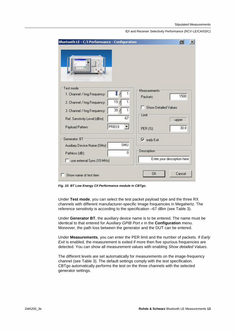
Stipulated Measurements
CI and Receiver Selectivity Performance (RCV-LECA03C)
1MA200_3e Rohde amp Schwarz Bluetooth LE Measurements 13
Fig 10 BT Low Energy CI Performance module in CBTgo
Under Test mode you can select the test packet payload type and the three RX
channels with different manufacturer-specific Image frequencies in Megahertz The
reference sensitivity is according to the specification ndash67 dBm (see Table 3)
Under Generator BT the auxiliary device name is to be entered The name must be
identical to that entered for Auxiliary GPIB Port x in the Configuration menu
Moreover the path loss between the generator and the DUT can be entered
Under Measurements you can enter the PER limit and the number of packets If Early
Exit is enabled the measurement is exited if more then five spurious frequencies are
detected You can show all measurement values with enabling Show detailed Values
The different levels are set automatically for measurements on the image-frequency
channel (see Table 3) The default settings comply with the test specification
CBTgo automatically performs the test on the three channels with the selected
generator settings
Stipulated Measurements
CI and Receiver Selectivity Performance (RCV-LECA03C)
1MA200_3e Rohde amp Schwarz Bluetooth LE Measurements 14
In the first test run all frequencies with a PER above the set limit are determined and
displayed In the second test run which is also performed automatically the DUTs
performance at these frequencies is retested with a CI of 17 dB This only takes
place for a maximum of five interference frequencies that are not
Co-channel
Adjacent channel plusmn 1 MHz
Image frequency
Adjacent channel to image frequency
With the settings in compliance with the test specification the measurement time is at
least four minutes (approx 1 second per PER measurement times 79 interferer channels times
three wanted channels)
Fig 11 shows a typical CI performance test report
Fig 11 CI performance test reports CBTgo shows the measurement results at the detected
spurious frequencies and a summary The repeated measurements with relaxed conditions is also
shown
Stipulated Measurements
Blocking Performance (RCV-LECA04C)
1MA200_3e Rohde amp Schwarz Bluetooth LE Measurements 15
32 Blocking Performance (RCV-LECA04C)
This measurement determines the receiver quality of the DUT if a continuous-wave
(CW) interferer is present outside the Bluetooth band The result is obtained by means
of a packet error rate (PER) measurement
The wanted signal is transmitted on a single channel in non-hopping mode A CW
interferer is likewise generated on a single channel coupled in and the BER is
determined In the next step the CW interferer is generated at intervals in consecutive
order over a specific frequency range and the PER is determined for each interferer
frequency (Fig 12)
Fig 12 Blocking performance For one channel the packet error rate in the presence of a CW
interferer outside the Bluetooth band is measured The measurement is repeated after shifting the
interferer by the frequency resolution
The Bluetooth test specification defines the following settings
DUT in direct RX mode
Hopping off (RX on single channel)
One channel (19)
Test packets with 37 octet PRBS9 payload
Interferer CW signal for levels and frequency ranges see Table 4
1500 packets
Wanted input level at EUT 67 dBm
Stipulated Measurements
Blocking Performance (RCV-LECA04C)
1MA200_3e Rohde amp Schwarz Bluetooth LE Measurements 16
Blocking level settings
Interference signal frequency Wanted
signal level
Blocking
signal level
Frequency
resolution
30 MHz to 2000 MHz ndash67 dBm ndash30 dBm 10 MHz
2003 MHz to 2399 MHz ndash67 dBm ndash35 dBm 3 MHz
2484 MHz to 2997 MHz ndash67 dBm ndash35 dBm 3 MHz
3000 MHz to 1275 GHz ndash67 dBm ndash30 dBm 25 MHz
Table 4 Blocking performance parameters first test run
Results
1st test run At each interferer frequency 1500 packets are measured The
frequencies at which a PER gt 308 is obtained are recorded The number of
frequencies recorded here must not exceed ten
2nd test run At each frequency recorded during the 1st test run 1500 packets are
measured at reduced interferer levels of ndash50 dBm The frequencies at which a
PER gt 308 is obtained are again recorded The PER limit may be exceeded for
a maximum of three frequencies
Test setup
Fig 13 shows a typical test setup The CBT and the DUT are connected to each other
by a combiner via which the interference signal from a CW generator is coupled in If
the DUT transmits at high power levels an attenuator may be inserted to protect the
generator
Fig 13 Test setup for blocking performance measurement
Stipulated Measurements
Blocking Performance (RCV-LECA04C)
1MA200_3e Rohde amp Schwarz Bluetooth LE Measurements 17
Measuring equipment and accessories
CBT tester SMx (SMF SMB SMR) generator up to 1275 GHz
Resistive combiner up to 1275 GHz (eg Weinschel 1515 1)
Attenuator up to 1275 GHz (eg Suhner) The measurement is performed using the BT Low Energy Blocking Performance module in CBTgo (Fig 14)
Fig 14 CBTgo BT Low Energy Blocking Performance module
Stipulated Measurements
Blocking Performance (RCV-LECA04C)
1MA200_3e Rohde amp Schwarz Bluetooth LE Measurements 18
Under Test mode you can select the test packet payload type The RX frequency of the measurement channel can be set The reference sensitivity level can be modified as required According to the specification this must be ndash67 dBm Under Generator CW the auxiliary device name is to be entered The name must be identical to that entered for Auxiliary GPIB Port x in the Configuration menu Moreover the path loss between the generator and the DUT can be set Under Blocking performance parameters the generator level as well as a start and a stop frequency can be entered in four columns In addition you can enter the measurement frequency resolution The default settings are the four ranges according to the specification (see Table 4) Under Measurements you can enter the PER limit the number of packets and the allowed exceptions for the two runs separately If Early Exit is enabled the measurement is exited if more then ten spurious frequencies are detected CBTgo automatically performs the test using the selected generator settings With the settings in compliance with the test specification the measurement time is at least 15 minutes (1 s per PER measurement times approx 890 interferer channels in the 1st test run) Fig 15 shows a typical entry in the test report
Stipulated Measurements
Blocking Performance (RCV-LECA04C)
1MA200_3e Rohde amp Schwarz Bluetooth LE Measurements 19
Fig 15 Blocking performance test report CBTgo shows the measurement results at the detected
spurious frequencies and a summary for the different sections The repeated measurements with
relaxed conditions are also shown
Stipulated Measurements
Intermodulation Performance (RCV-LECA05C)
1MA200_3e Rohde amp Schwarz Bluetooth LE Measurements 20
33 Intermodulation Performance (RCV-LECA05C)
This measurement verifies the intermodulation performance of the DUTs receiver A
PER measurement is performed using two interferers that cause intermodulation at the
DUTs receive frequency
The wanted signal is transmitted on a single channel in non-hopping mode A CW
interferer spaced +n MHz and a Bluetooth interferer spaced +2n MHz from the wanted
signal are generated coupled in and the PER is determined The measurement is
then performed with the interferers at ndashn MHz and ndash2n MHz The two measurements
are repeated on two more wanted channels (Fig 16)
Fig 16 Intermodulation performance For each of three channels the packet error rate in the
presence of a CW interferer in a distance n and in the presence of a Bluetooth interferer in a distance
2n is measured
The Bluetooth test specification defines the following settings
Hopping off (RX on single channel)
Three channels (0 19 39)
PRBS9
Wanted signal level at ndash64 dBm
n = 3 4 or 5 (defined by manufacturer)
Bluetooth interferer low energy GFSK with PRBS15 spaced plusmn2n MHz from wanted
signal level ndash50 dBm
CW interferer spaced plusmnn MHz from wanted signal level ndash50 dBm
1500 packets
Result
A PER of 308 must be obtained for each of the three channels
Stipulated Measurements
Intermodulation Performance (RCV-LECA05C)
1MA200_3e Rohde amp Schwarz Bluetooth LE Measurements 21
Test setup
The two interferer signals required in this measurement are supplied via two generator
paths that are combined via a hybrid combiner The resulting signal is coupled into the
line connecting the CBT and the DUT via a second hybrid combiner If a dual-channel
SMU is used one generator is sufficient (Fig 17) otherwise two generators are
required (Fig 18)
Fig 17 Test setup 1 for intermodulation performance measurement using one generator
Stipulated Measurements
Intermodulation Performance (RCV-LECA05C)
1MA200_3e Rohde amp Schwarz Bluetooth LE Measurements 22
Fig 18 Test setup 2 for intermodulation performance using two generators
Measuring equipment and accessories
CBT tester SMU or SMJ + SMF or SMB or SMR signal generators
Two hybrid combiners (eg Minicircuits ZFSC 2 2500)
The measurement is performed using the BT Low Energy Intermodulation
Performance module in CBTgo (Fig 19)
Stipulated Measurements
Intermodulation Performance (RCV-LECA05C)
1MA200_3e Rohde amp Schwarz Bluetooth LE Measurements 23
Fig 19 CBTgo BT Low Energy Intermodulation Performance module
Under Test Mode you can select the test packet payload type The RX frequencies of the three channels can be set The reference sensitivity level can be modified as required According to the specification this must be ndash 64 dBm
Under Generator 1 and Generator 2 the auxiliary device name is to be entered The
name must be identical to that entered for Auxiliary GPIB Port x in the Configuration
menu The intermodulation distance n (spacing from wanted signal) must be selected
Moreover the path loss between the generator and the DUT as well as the
interference level can be entered for each generator A second generator can be
included in the test setup if the first generator does not offer dual-channel capability
Stipulated Measurements
Intermodulation Performance (RCV-LECA05C)
1MA200_3e Rohde amp Schwarz Bluetooth LE Measurements 24
Under Measurements you can enter the PER limit and the number of packets The
default settings comply with the test specification
CBTgo automatically performs the test on the three channels using the selected
generator settings
Fig 20 shows a typical entry in the test report
Fig 20 Low energy intermodulation performance test report
Appendix
References
1MA200_3e Rohde amp Schwarz Bluetooth LE Measurements 25
4 Appendix
41 References
[1] Bluetooth Test amp Interoperability Working Group Bluetooth Low Energy RF PHY
Test Specification RF-PHYTS402 122012 Bluetooth SIG Inc
[2] Rohde amp Schwarz Manual for Windows Application CBTgo (V170)
[3] Rohde amp Schwarz Measurements on Bluetooth Products using
RampS CMU200CBT and CMUgoCBTgo Application Note 1CM50 102006
[4] Rohde amp Schwarz Bluetooth Measurements Using CBTgo Additional Tests Application Note 1MA106 022013
42 Additional Information
Please send your comments and suggestions regarding this application note to
TM-Applicationsrohde-schwarzcom
Visit the CBTgo website at
httpwww2rohde-
schwarzcomenproductstest_and_measurementmobile_radioCBT_CBT32-|-
Tools-|-67-|-1459html
or as a registered user in GLORIS the CMU Customer Web at
httpsextranetrohde-schwarzcom
Appendix
Ordering Information
1MA200_3e Rohde amp Schwarz Bluetooth LE Measurements 26
43 Ordering Information
Ordering information
Bluetooth tester
CBT Bluetooth tester with display 1153900035
CBT32 Bluetooth tester without display 1153900032
CBT-K57 Bluetooth Low Energy 1170410202
Vector signal generator
SMU200A Vector Signal Generator 1141200502
SMU-B9 Baseband Generator 128 Msample 1161076602
SMU-B10 Baseband Generator 64 Msample 1141700702
SMU-B11 Baseband Generator 16 Msample 1159841102
SMU-B13 Baseband Main Module 1141800304
SMU-B10x RF Path A
SMU-B20x RF Path B
SMW200A Vector Signal Generator 1412000002
SMW-B10 Baseband Generator with ARB
(64 Msample) and Digital Modulation
(realtime) 120 MHz RF bandwidth
1413120002
SMW-B13 Baseband Main Module one IQ path to RF 1413280702
SMW-B10x RF Path A
SMW-B20x RF Path B
SMBV100A Vector Signal Generator 1407600402
Signal generator
SMF100A Microwave Signal Generator
up to 435 GHz
1167000002
SMB100A RF and Microwave Signal Generator
up to 1275 GHz
1406600002
xx stands for the different frequency ranges (eg 1155500126 MHz to 26 GHz
Note Available options are not listed in detail
Please contact your local Rohde amp Schwarz sales office for further assistance
About Rohde amp Schwarz
Rohde amp Schwarz is an independent group
of companies specializing in electronics It is
a leading supplier of solutions in the fields of
test and measurement broadcasting
radiomonitoring and radiolocation as well as
secure communications Established more
than 75 years ago Rohde amp Schwarz has a
global presence and a dedicated service
network in over 70 countries Company
headquarters are in Munich Germany
Environmental commitment
Energy-efficient products
Continuous improvement in
environmental sustainability
ISO 14001-certified environmental
management system
Regional contact
Europe Africa Middle East
+49 89 4129 12345
customersupportrohde-schwarzcom North America
1-888-TEST-RSA (1-888-837-8772)
customersupportrsarohde-schwarzcom Latin America
+1-410-910-7988
customersupportlarohde-schwarzcom AsiaPacific
+65 65 13 04 88
customersupportasiarohde-schwarzcom
This application note and the supplied
programs may only be used subject to the
conditions of use set forth in the download
area of the Rohde amp Schwarz website
RampSreg is a registered trademark of Rohde amp Schwarz GmbH amp Co KG Trade names are trademarks of the owners
Rohde amp Schwarz GmbH amp Co KG
Muumlhldorfstraszlige 15 | D - 81671 Muumlnchen
Phone + 49 89 4129 - 0 | Fax + 49 89 4129 ndash 13777
wwwrohde-schwarzcom
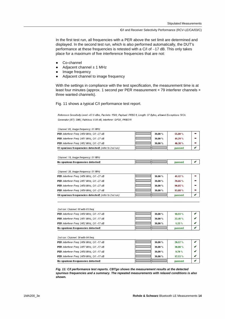
Stipulated Measurements
CI and Receiver Selectivity Performance (RCV-LECA03C)
1MA200_3e Rohde amp Schwarz Bluetooth LE Measurements 14
In the first test run all frequencies with a PER above the set limit are determined and
displayed In the second test run which is also performed automatically the DUTs
performance at these frequencies is retested with a CI of 17 dB This only takes
place for a maximum of five interference frequencies that are not
Co-channel
Adjacent channel plusmn 1 MHz
Image frequency
Adjacent channel to image frequency
With the settings in compliance with the test specification the measurement time is at
least four minutes (approx 1 second per PER measurement times 79 interferer channels times
three wanted channels)
Fig 11 shows a typical CI performance test report
Fig 11 CI performance test reports CBTgo shows the measurement results at the detected
spurious frequencies and a summary The repeated measurements with relaxed conditions is also
shown
Stipulated Measurements
Blocking Performance (RCV-LECA04C)
1MA200_3e Rohde amp Schwarz Bluetooth LE Measurements 15
32 Blocking Performance (RCV-LECA04C)
This measurement determines the receiver quality of the DUT if a continuous-wave
(CW) interferer is present outside the Bluetooth band The result is obtained by means
of a packet error rate (PER) measurement
The wanted signal is transmitted on a single channel in non-hopping mode A CW
interferer is likewise generated on a single channel coupled in and the BER is
determined In the next step the CW interferer is generated at intervals in consecutive
order over a specific frequency range and the PER is determined for each interferer
frequency (Fig 12)
Fig 12 Blocking performance For one channel the packet error rate in the presence of a CW
interferer outside the Bluetooth band is measured The measurement is repeated after shifting the
interferer by the frequency resolution
The Bluetooth test specification defines the following settings
DUT in direct RX mode
Hopping off (RX on single channel)
One channel (19)
Test packets with 37 octet PRBS9 payload
Interferer CW signal for levels and frequency ranges see Table 4
1500 packets
Wanted input level at EUT 67 dBm
Stipulated Measurements
Blocking Performance (RCV-LECA04C)
1MA200_3e Rohde amp Schwarz Bluetooth LE Measurements 16
Blocking level settings
Interference signal frequency Wanted
signal level
Blocking
signal level
Frequency
resolution
30 MHz to 2000 MHz ndash67 dBm ndash30 dBm 10 MHz
2003 MHz to 2399 MHz ndash67 dBm ndash35 dBm 3 MHz
2484 MHz to 2997 MHz ndash67 dBm ndash35 dBm 3 MHz
3000 MHz to 1275 GHz ndash67 dBm ndash30 dBm 25 MHz
Table 4 Blocking performance parameters first test run
Results
1st test run At each interferer frequency 1500 packets are measured The
frequencies at which a PER gt 308 is obtained are recorded The number of
frequencies recorded here must not exceed ten
2nd test run At each frequency recorded during the 1st test run 1500 packets are
measured at reduced interferer levels of ndash50 dBm The frequencies at which a
PER gt 308 is obtained are again recorded The PER limit may be exceeded for
a maximum of three frequencies
Test setup
Fig 13 shows a typical test setup The CBT and the DUT are connected to each other
by a combiner via which the interference signal from a CW generator is coupled in If
the DUT transmits at high power levels an attenuator may be inserted to protect the
generator
Fig 13 Test setup for blocking performance measurement
Stipulated Measurements
Blocking Performance (RCV-LECA04C)
1MA200_3e Rohde amp Schwarz Bluetooth LE Measurements 17
Measuring equipment and accessories
CBT tester SMx (SMF SMB SMR) generator up to 1275 GHz
Resistive combiner up to 1275 GHz (eg Weinschel 1515 1)
Attenuator up to 1275 GHz (eg Suhner) The measurement is performed using the BT Low Energy Blocking Performance module in CBTgo (Fig 14)
Fig 14 CBTgo BT Low Energy Blocking Performance module
Stipulated Measurements
Blocking Performance (RCV-LECA04C)
1MA200_3e Rohde amp Schwarz Bluetooth LE Measurements 18
Under Test mode you can select the test packet payload type The RX frequency of the measurement channel can be set The reference sensitivity level can be modified as required According to the specification this must be ndash67 dBm Under Generator CW the auxiliary device name is to be entered The name must be identical to that entered for Auxiliary GPIB Port x in the Configuration menu Moreover the path loss between the generator and the DUT can be set Under Blocking performance parameters the generator level as well as a start and a stop frequency can be entered in four columns In addition you can enter the measurement frequency resolution The default settings are the four ranges according to the specification (see Table 4) Under Measurements you can enter the PER limit the number of packets and the allowed exceptions for the two runs separately If Early Exit is enabled the measurement is exited if more then ten spurious frequencies are detected CBTgo automatically performs the test using the selected generator settings With the settings in compliance with the test specification the measurement time is at least 15 minutes (1 s per PER measurement times approx 890 interferer channels in the 1st test run) Fig 15 shows a typical entry in the test report
Stipulated Measurements
Blocking Performance (RCV-LECA04C)
1MA200_3e Rohde amp Schwarz Bluetooth LE Measurements 19
Fig 15 Blocking performance test report CBTgo shows the measurement results at the detected
spurious frequencies and a summary for the different sections The repeated measurements with
relaxed conditions are also shown
Stipulated Measurements
Intermodulation Performance (RCV-LECA05C)
1MA200_3e Rohde amp Schwarz Bluetooth LE Measurements 20
33 Intermodulation Performance (RCV-LECA05C)
This measurement verifies the intermodulation performance of the DUTs receiver A
PER measurement is performed using two interferers that cause intermodulation at the
DUTs receive frequency
The wanted signal is transmitted on a single channel in non-hopping mode A CW
interferer spaced +n MHz and a Bluetooth interferer spaced +2n MHz from the wanted
signal are generated coupled in and the PER is determined The measurement is
then performed with the interferers at ndashn MHz and ndash2n MHz The two measurements
are repeated on two more wanted channels (Fig 16)
Fig 16 Intermodulation performance For each of three channels the packet error rate in the
presence of a CW interferer in a distance n and in the presence of a Bluetooth interferer in a distance
2n is measured
The Bluetooth test specification defines the following settings
Hopping off (RX on single channel)
Three channels (0 19 39)
PRBS9
Wanted signal level at ndash64 dBm
n = 3 4 or 5 (defined by manufacturer)
Bluetooth interferer low energy GFSK with PRBS15 spaced plusmn2n MHz from wanted
signal level ndash50 dBm
CW interferer spaced plusmnn MHz from wanted signal level ndash50 dBm
1500 packets
Result
A PER of 308 must be obtained for each of the three channels
Stipulated Measurements
Intermodulation Performance (RCV-LECA05C)
1MA200_3e Rohde amp Schwarz Bluetooth LE Measurements 21
Test setup
The two interferer signals required in this measurement are supplied via two generator
paths that are combined via a hybrid combiner The resulting signal is coupled into the
line connecting the CBT and the DUT via a second hybrid combiner If a dual-channel
SMU is used one generator is sufficient (Fig 17) otherwise two generators are
required (Fig 18)
Fig 17 Test setup 1 for intermodulation performance measurement using one generator
Stipulated Measurements
Intermodulation Performance (RCV-LECA05C)
1MA200_3e Rohde amp Schwarz Bluetooth LE Measurements 22
Fig 18 Test setup 2 for intermodulation performance using two generators
Measuring equipment and accessories
CBT tester SMU or SMJ + SMF or SMB or SMR signal generators
Two hybrid combiners (eg Minicircuits ZFSC 2 2500)
The measurement is performed using the BT Low Energy Intermodulation
Performance module in CBTgo (Fig 19)
Stipulated Measurements
Intermodulation Performance (RCV-LECA05C)
1MA200_3e Rohde amp Schwarz Bluetooth LE Measurements 23
Fig 19 CBTgo BT Low Energy Intermodulation Performance module
Under Test Mode you can select the test packet payload type The RX frequencies of the three channels can be set The reference sensitivity level can be modified as required According to the specification this must be ndash 64 dBm
Under Generator 1 and Generator 2 the auxiliary device name is to be entered The
name must be identical to that entered for Auxiliary GPIB Port x in the Configuration
menu The intermodulation distance n (spacing from wanted signal) must be selected
Moreover the path loss between the generator and the DUT as well as the
interference level can be entered for each generator A second generator can be
included in the test setup if the first generator does not offer dual-channel capability
Stipulated Measurements
Intermodulation Performance (RCV-LECA05C)
1MA200_3e Rohde amp Schwarz Bluetooth LE Measurements 24
Under Measurements you can enter the PER limit and the number of packets The
default settings comply with the test specification
CBTgo automatically performs the test on the three channels using the selected
generator settings
Fig 20 shows a typical entry in the test report
Fig 20 Low energy intermodulation performance test report
Appendix
References
1MA200_3e Rohde amp Schwarz Bluetooth LE Measurements 25
4 Appendix
41 References
[1] Bluetooth Test amp Interoperability Working Group Bluetooth Low Energy RF PHY
Test Specification RF-PHYTS402 122012 Bluetooth SIG Inc
[2] Rohde amp Schwarz Manual for Windows Application CBTgo (V170)
[3] Rohde amp Schwarz Measurements on Bluetooth Products using
RampS CMU200CBT and CMUgoCBTgo Application Note 1CM50 102006
[4] Rohde amp Schwarz Bluetooth Measurements Using CBTgo Additional Tests Application Note 1MA106 022013
42 Additional Information
Please send your comments and suggestions regarding this application note to
TM-Applicationsrohde-schwarzcom
Visit the CBTgo website at
httpwww2rohde-
schwarzcomenproductstest_and_measurementmobile_radioCBT_CBT32-|-
Tools-|-67-|-1459html
or as a registered user in GLORIS the CMU Customer Web at
httpsextranetrohde-schwarzcom
Appendix
Ordering Information
1MA200_3e Rohde amp Schwarz Bluetooth LE Measurements 26
43 Ordering Information
Ordering information
Bluetooth tester
CBT Bluetooth tester with display 1153900035
CBT32 Bluetooth tester without display 1153900032
CBT-K57 Bluetooth Low Energy 1170410202
Vector signal generator
SMU200A Vector Signal Generator 1141200502
SMU-B9 Baseband Generator 128 Msample 1161076602
SMU-B10 Baseband Generator 64 Msample 1141700702
SMU-B11 Baseband Generator 16 Msample 1159841102
SMU-B13 Baseband Main Module 1141800304
SMU-B10x RF Path A
SMU-B20x RF Path B
SMW200A Vector Signal Generator 1412000002
SMW-B10 Baseband Generator with ARB
(64 Msample) and Digital Modulation
(realtime) 120 MHz RF bandwidth
1413120002
SMW-B13 Baseband Main Module one IQ path to RF 1413280702
SMW-B10x RF Path A
SMW-B20x RF Path B
SMBV100A Vector Signal Generator 1407600402
Signal generator
SMF100A Microwave Signal Generator
up to 435 GHz
1167000002
SMB100A RF and Microwave Signal Generator
up to 1275 GHz
1406600002
xx stands for the different frequency ranges (eg 1155500126 MHz to 26 GHz
Note Available options are not listed in detail
Please contact your local Rohde amp Schwarz sales office for further assistance
About Rohde amp Schwarz
Rohde amp Schwarz is an independent group
of companies specializing in electronics It is
a leading supplier of solutions in the fields of
test and measurement broadcasting
radiomonitoring and radiolocation as well as
secure communications Established more
than 75 years ago Rohde amp Schwarz has a
global presence and a dedicated service
network in over 70 countries Company
headquarters are in Munich Germany
Environmental commitment
Energy-efficient products
Continuous improvement in
environmental sustainability
ISO 14001-certified environmental
management system
Regional contact
Europe Africa Middle East
+49 89 4129 12345
customersupportrohde-schwarzcom North America
1-888-TEST-RSA (1-888-837-8772)
customersupportrsarohde-schwarzcom Latin America
+1-410-910-7988
customersupportlarohde-schwarzcom AsiaPacific
+65 65 13 04 88
customersupportasiarohde-schwarzcom
This application note and the supplied
programs may only be used subject to the
conditions of use set forth in the download
area of the Rohde amp Schwarz website
RampSreg is a registered trademark of Rohde amp Schwarz GmbH amp Co KG Trade names are trademarks of the owners
Rohde amp Schwarz GmbH amp Co KG
Muumlhldorfstraszlige 15 | D - 81671 Muumlnchen
Phone + 49 89 4129 - 0 | Fax + 49 89 4129 ndash 13777
wwwrohde-schwarzcom
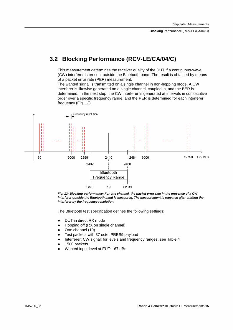
Stipulated Measurements
Blocking Performance (RCV-LECA04C)
1MA200_3e Rohde amp Schwarz Bluetooth LE Measurements 15
32 Blocking Performance (RCV-LECA04C)
This measurement determines the receiver quality of the DUT if a continuous-wave
(CW) interferer is present outside the Bluetooth band The result is obtained by means
of a packet error rate (PER) measurement
The wanted signal is transmitted on a single channel in non-hopping mode A CW
interferer is likewise generated on a single channel coupled in and the BER is
determined In the next step the CW interferer is generated at intervals in consecutive
order over a specific frequency range and the PER is determined for each interferer
frequency (Fig 12)
Fig 12 Blocking performance For one channel the packet error rate in the presence of a CW
interferer outside the Bluetooth band is measured The measurement is repeated after shifting the
interferer by the frequency resolution
The Bluetooth test specification defines the following settings
DUT in direct RX mode
Hopping off (RX on single channel)
One channel (19)
Test packets with 37 octet PRBS9 payload
Interferer CW signal for levels and frequency ranges see Table 4
1500 packets
Wanted input level at EUT 67 dBm
Stipulated Measurements
Blocking Performance (RCV-LECA04C)
1MA200_3e Rohde amp Schwarz Bluetooth LE Measurements 16
Blocking level settings
Interference signal frequency Wanted
signal level
Blocking
signal level
Frequency
resolution
30 MHz to 2000 MHz ndash67 dBm ndash30 dBm 10 MHz
2003 MHz to 2399 MHz ndash67 dBm ndash35 dBm 3 MHz
2484 MHz to 2997 MHz ndash67 dBm ndash35 dBm 3 MHz
3000 MHz to 1275 GHz ndash67 dBm ndash30 dBm 25 MHz
Table 4 Blocking performance parameters first test run
Results
1st test run At each interferer frequency 1500 packets are measured The
frequencies at which a PER gt 308 is obtained are recorded The number of
frequencies recorded here must not exceed ten
2nd test run At each frequency recorded during the 1st test run 1500 packets are
measured at reduced interferer levels of ndash50 dBm The frequencies at which a
PER gt 308 is obtained are again recorded The PER limit may be exceeded for
a maximum of three frequencies
Test setup
Fig 13 shows a typical test setup The CBT and the DUT are connected to each other
by a combiner via which the interference signal from a CW generator is coupled in If
the DUT transmits at high power levels an attenuator may be inserted to protect the
generator
Fig 13 Test setup for blocking performance measurement
Stipulated Measurements
Blocking Performance (RCV-LECA04C)
1MA200_3e Rohde amp Schwarz Bluetooth LE Measurements 17
Measuring equipment and accessories
CBT tester SMx (SMF SMB SMR) generator up to 1275 GHz
Resistive combiner up to 1275 GHz (eg Weinschel 1515 1)
Attenuator up to 1275 GHz (eg Suhner) The measurement is performed using the BT Low Energy Blocking Performance module in CBTgo (Fig 14)
Fig 14 CBTgo BT Low Energy Blocking Performance module
Stipulated Measurements
Blocking Performance (RCV-LECA04C)
1MA200_3e Rohde amp Schwarz Bluetooth LE Measurements 18
Under Test mode you can select the test packet payload type The RX frequency of the measurement channel can be set The reference sensitivity level can be modified as required According to the specification this must be ndash67 dBm Under Generator CW the auxiliary device name is to be entered The name must be identical to that entered for Auxiliary GPIB Port x in the Configuration menu Moreover the path loss between the generator and the DUT can be set Under Blocking performance parameters the generator level as well as a start and a stop frequency can be entered in four columns In addition you can enter the measurement frequency resolution The default settings are the four ranges according to the specification (see Table 4) Under Measurements you can enter the PER limit the number of packets and the allowed exceptions for the two runs separately If Early Exit is enabled the measurement is exited if more then ten spurious frequencies are detected CBTgo automatically performs the test using the selected generator settings With the settings in compliance with the test specification the measurement time is at least 15 minutes (1 s per PER measurement times approx 890 interferer channels in the 1st test run) Fig 15 shows a typical entry in the test report
Stipulated Measurements
Blocking Performance (RCV-LECA04C)
1MA200_3e Rohde amp Schwarz Bluetooth LE Measurements 19
Fig 15 Blocking performance test report CBTgo shows the measurement results at the detected
spurious frequencies and a summary for the different sections The repeated measurements with
relaxed conditions are also shown
Stipulated Measurements
Intermodulation Performance (RCV-LECA05C)
1MA200_3e Rohde amp Schwarz Bluetooth LE Measurements 20
33 Intermodulation Performance (RCV-LECA05C)
This measurement verifies the intermodulation performance of the DUTs receiver A
PER measurement is performed using two interferers that cause intermodulation at the
DUTs receive frequency
The wanted signal is transmitted on a single channel in non-hopping mode A CW
interferer spaced +n MHz and a Bluetooth interferer spaced +2n MHz from the wanted
signal are generated coupled in and the PER is determined The measurement is
then performed with the interferers at ndashn MHz and ndash2n MHz The two measurements
are repeated on two more wanted channels (Fig 16)
Fig 16 Intermodulation performance For each of three channels the packet error rate in the
presence of a CW interferer in a distance n and in the presence of a Bluetooth interferer in a distance
2n is measured
The Bluetooth test specification defines the following settings
Hopping off (RX on single channel)
Three channels (0 19 39)
PRBS9
Wanted signal level at ndash64 dBm
n = 3 4 or 5 (defined by manufacturer)
Bluetooth interferer low energy GFSK with PRBS15 spaced plusmn2n MHz from wanted
signal level ndash50 dBm
CW interferer spaced plusmnn MHz from wanted signal level ndash50 dBm
1500 packets
Result
A PER of 308 must be obtained for each of the three channels
Stipulated Measurements
Intermodulation Performance (RCV-LECA05C)
1MA200_3e Rohde amp Schwarz Bluetooth LE Measurements 21
Test setup
The two interferer signals required in this measurement are supplied via two generator
paths that are combined via a hybrid combiner The resulting signal is coupled into the
line connecting the CBT and the DUT via a second hybrid combiner If a dual-channel
SMU is used one generator is sufficient (Fig 17) otherwise two generators are
required (Fig 18)
Fig 17 Test setup 1 for intermodulation performance measurement using one generator
Stipulated Measurements
Intermodulation Performance (RCV-LECA05C)
1MA200_3e Rohde amp Schwarz Bluetooth LE Measurements 22
Fig 18 Test setup 2 for intermodulation performance using two generators
Measuring equipment and accessories
CBT tester SMU or SMJ + SMF or SMB or SMR signal generators
Two hybrid combiners (eg Minicircuits ZFSC 2 2500)
The measurement is performed using the BT Low Energy Intermodulation
Performance module in CBTgo (Fig 19)
Stipulated Measurements
Intermodulation Performance (RCV-LECA05C)
1MA200_3e Rohde amp Schwarz Bluetooth LE Measurements 23
Fig 19 CBTgo BT Low Energy Intermodulation Performance module
Under Test Mode you can select the test packet payload type The RX frequencies of the three channels can be set The reference sensitivity level can be modified as required According to the specification this must be ndash 64 dBm
Under Generator 1 and Generator 2 the auxiliary device name is to be entered The
name must be identical to that entered for Auxiliary GPIB Port x in the Configuration
menu The intermodulation distance n (spacing from wanted signal) must be selected
Moreover the path loss between the generator and the DUT as well as the
interference level can be entered for each generator A second generator can be
included in the test setup if the first generator does not offer dual-channel capability
Stipulated Measurements
Intermodulation Performance (RCV-LECA05C)
1MA200_3e Rohde amp Schwarz Bluetooth LE Measurements 24
Under Measurements you can enter the PER limit and the number of packets The
default settings comply with the test specification
CBTgo automatically performs the test on the three channels using the selected
generator settings
Fig 20 shows a typical entry in the test report
Fig 20 Low energy intermodulation performance test report
Appendix
References
1MA200_3e Rohde amp Schwarz Bluetooth LE Measurements 25
4 Appendix
41 References
[1] Bluetooth Test amp Interoperability Working Group Bluetooth Low Energy RF PHY
Test Specification RF-PHYTS402 122012 Bluetooth SIG Inc
[2] Rohde amp Schwarz Manual for Windows Application CBTgo (V170)
[3] Rohde amp Schwarz Measurements on Bluetooth Products using
RampS CMU200CBT and CMUgoCBTgo Application Note 1CM50 102006
[4] Rohde amp Schwarz Bluetooth Measurements Using CBTgo Additional Tests Application Note 1MA106 022013
42 Additional Information
Please send your comments and suggestions regarding this application note to
TM-Applicationsrohde-schwarzcom
Visit the CBTgo website at
httpwww2rohde-
schwarzcomenproductstest_and_measurementmobile_radioCBT_CBT32-|-
Tools-|-67-|-1459html
or as a registered user in GLORIS the CMU Customer Web at
httpsextranetrohde-schwarzcom
Appendix
Ordering Information
1MA200_3e Rohde amp Schwarz Bluetooth LE Measurements 26
43 Ordering Information
Ordering information
Bluetooth tester
CBT Bluetooth tester with display 1153900035
CBT32 Bluetooth tester without display 1153900032
CBT-K57 Bluetooth Low Energy 1170410202
Vector signal generator
SMU200A Vector Signal Generator 1141200502
SMU-B9 Baseband Generator 128 Msample 1161076602
SMU-B10 Baseband Generator 64 Msample 1141700702
SMU-B11 Baseband Generator 16 Msample 1159841102
SMU-B13 Baseband Main Module 1141800304
SMU-B10x RF Path A
SMU-B20x RF Path B
SMW200A Vector Signal Generator 1412000002
SMW-B10 Baseband Generator with ARB
(64 Msample) and Digital Modulation
(realtime) 120 MHz RF bandwidth
1413120002
SMW-B13 Baseband Main Module one IQ path to RF 1413280702
SMW-B10x RF Path A
SMW-B20x RF Path B
SMBV100A Vector Signal Generator 1407600402
Signal generator
SMF100A Microwave Signal Generator
up to 435 GHz
1167000002
SMB100A RF and Microwave Signal Generator
up to 1275 GHz
1406600002
xx stands for the different frequency ranges (eg 1155500126 MHz to 26 GHz
Note Available options are not listed in detail
Please contact your local Rohde amp Schwarz sales office for further assistance
About Rohde amp Schwarz
Rohde amp Schwarz is an independent group
of companies specializing in electronics It is
a leading supplier of solutions in the fields of
test and measurement broadcasting
radiomonitoring and radiolocation as well as
secure communications Established more
than 75 years ago Rohde amp Schwarz has a
global presence and a dedicated service
network in over 70 countries Company
headquarters are in Munich Germany
Environmental commitment
Energy-efficient products
Continuous improvement in
environmental sustainability
ISO 14001-certified environmental
management system
Regional contact
Europe Africa Middle East
+49 89 4129 12345
customersupportrohde-schwarzcom North America
1-888-TEST-RSA (1-888-837-8772)
customersupportrsarohde-schwarzcom Latin America
+1-410-910-7988
customersupportlarohde-schwarzcom AsiaPacific
+65 65 13 04 88
customersupportasiarohde-schwarzcom
This application note and the supplied
programs may only be used subject to the
conditions of use set forth in the download
area of the Rohde amp Schwarz website
RampSreg is a registered trademark of Rohde amp Schwarz GmbH amp Co KG Trade names are trademarks of the owners
Rohde amp Schwarz GmbH amp Co KG
Muumlhldorfstraszlige 15 | D - 81671 Muumlnchen
Phone + 49 89 4129 - 0 | Fax + 49 89 4129 ndash 13777
wwwrohde-schwarzcom
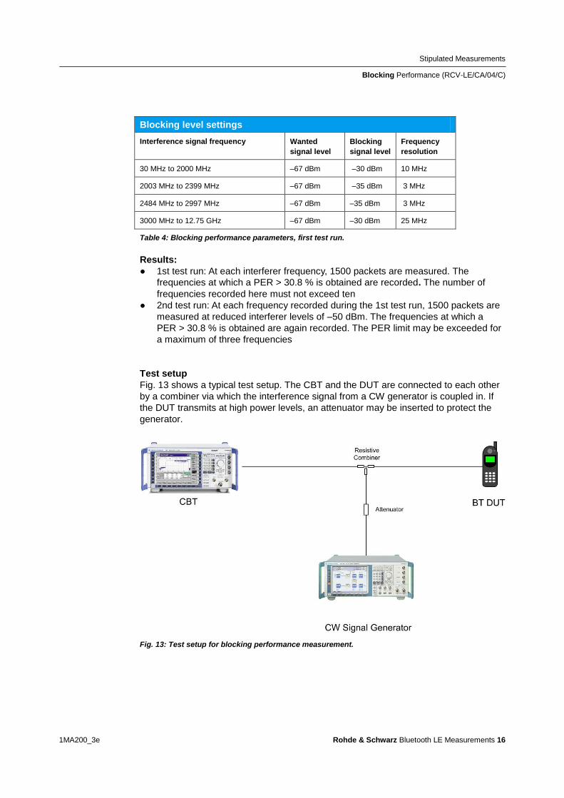
Stipulated Measurements
Blocking Performance (RCV-LECA04C)
1MA200_3e Rohde amp Schwarz Bluetooth LE Measurements 16
Blocking level settings
Interference signal frequency Wanted
signal level
Blocking
signal level
Frequency
resolution
30 MHz to 2000 MHz ndash67 dBm ndash30 dBm 10 MHz
2003 MHz to 2399 MHz ndash67 dBm ndash35 dBm 3 MHz
2484 MHz to 2997 MHz ndash67 dBm ndash35 dBm 3 MHz
3000 MHz to 1275 GHz ndash67 dBm ndash30 dBm 25 MHz
Table 4 Blocking performance parameters first test run
Results
1st test run At each interferer frequency 1500 packets are measured The
frequencies at which a PER gt 308 is obtained are recorded The number of
frequencies recorded here must not exceed ten
2nd test run At each frequency recorded during the 1st test run 1500 packets are
measured at reduced interferer levels of ndash50 dBm The frequencies at which a
PER gt 308 is obtained are again recorded The PER limit may be exceeded for
a maximum of three frequencies
Test setup
Fig 13 shows a typical test setup The CBT and the DUT are connected to each other
by a combiner via which the interference signal from a CW generator is coupled in If
the DUT transmits at high power levels an attenuator may be inserted to protect the
generator
Fig 13 Test setup for blocking performance measurement
Stipulated Measurements
Blocking Performance (RCV-LECA04C)
1MA200_3e Rohde amp Schwarz Bluetooth LE Measurements 17
Measuring equipment and accessories
CBT tester SMx (SMF SMB SMR) generator up to 1275 GHz
Resistive combiner up to 1275 GHz (eg Weinschel 1515 1)
Attenuator up to 1275 GHz (eg Suhner) The measurement is performed using the BT Low Energy Blocking Performance module in CBTgo (Fig 14)
Fig 14 CBTgo BT Low Energy Blocking Performance module
Stipulated Measurements
Blocking Performance (RCV-LECA04C)
1MA200_3e Rohde amp Schwarz Bluetooth LE Measurements 18
Under Test mode you can select the test packet payload type The RX frequency of the measurement channel can be set The reference sensitivity level can be modified as required According to the specification this must be ndash67 dBm Under Generator CW the auxiliary device name is to be entered The name must be identical to that entered for Auxiliary GPIB Port x in the Configuration menu Moreover the path loss between the generator and the DUT can be set Under Blocking performance parameters the generator level as well as a start and a stop frequency can be entered in four columns In addition you can enter the measurement frequency resolution The default settings are the four ranges according to the specification (see Table 4) Under Measurements you can enter the PER limit the number of packets and the allowed exceptions for the two runs separately If Early Exit is enabled the measurement is exited if more then ten spurious frequencies are detected CBTgo automatically performs the test using the selected generator settings With the settings in compliance with the test specification the measurement time is at least 15 minutes (1 s per PER measurement times approx 890 interferer channels in the 1st test run) Fig 15 shows a typical entry in the test report
Stipulated Measurements
Blocking Performance (RCV-LECA04C)
1MA200_3e Rohde amp Schwarz Bluetooth LE Measurements 19
Fig 15 Blocking performance test report CBTgo shows the measurement results at the detected
spurious frequencies and a summary for the different sections The repeated measurements with
relaxed conditions are also shown
Stipulated Measurements
Intermodulation Performance (RCV-LECA05C)
1MA200_3e Rohde amp Schwarz Bluetooth LE Measurements 20
33 Intermodulation Performance (RCV-LECA05C)
This measurement verifies the intermodulation performance of the DUTs receiver A
PER measurement is performed using two interferers that cause intermodulation at the
DUTs receive frequency
The wanted signal is transmitted on a single channel in non-hopping mode A CW
interferer spaced +n MHz and a Bluetooth interferer spaced +2n MHz from the wanted
signal are generated coupled in and the PER is determined The measurement is
then performed with the interferers at ndashn MHz and ndash2n MHz The two measurements
are repeated on two more wanted channels (Fig 16)
Fig 16 Intermodulation performance For each of three channels the packet error rate in the
presence of a CW interferer in a distance n and in the presence of a Bluetooth interferer in a distance
2n is measured
The Bluetooth test specification defines the following settings
Hopping off (RX on single channel)
Three channels (0 19 39)
PRBS9
Wanted signal level at ndash64 dBm
n = 3 4 or 5 (defined by manufacturer)
Bluetooth interferer low energy GFSK with PRBS15 spaced plusmn2n MHz from wanted
signal level ndash50 dBm
CW interferer spaced plusmnn MHz from wanted signal level ndash50 dBm
1500 packets
Result
A PER of 308 must be obtained for each of the three channels
Stipulated Measurements
Intermodulation Performance (RCV-LECA05C)
1MA200_3e Rohde amp Schwarz Bluetooth LE Measurements 21
Test setup
The two interferer signals required in this measurement are supplied via two generator
paths that are combined via a hybrid combiner The resulting signal is coupled into the
line connecting the CBT and the DUT via a second hybrid combiner If a dual-channel
SMU is used one generator is sufficient (Fig 17) otherwise two generators are
required (Fig 18)
Fig 17 Test setup 1 for intermodulation performance measurement using one generator
Stipulated Measurements
Intermodulation Performance (RCV-LECA05C)
1MA200_3e Rohde amp Schwarz Bluetooth LE Measurements 22
Fig 18 Test setup 2 for intermodulation performance using two generators
Measuring equipment and accessories
CBT tester SMU or SMJ + SMF or SMB or SMR signal generators
Two hybrid combiners (eg Minicircuits ZFSC 2 2500)
The measurement is performed using the BT Low Energy Intermodulation
Performance module in CBTgo (Fig 19)
Stipulated Measurements
Intermodulation Performance (RCV-LECA05C)
1MA200_3e Rohde amp Schwarz Bluetooth LE Measurements 23
Fig 19 CBTgo BT Low Energy Intermodulation Performance module
Under Test Mode you can select the test packet payload type The RX frequencies of the three channels can be set The reference sensitivity level can be modified as required According to the specification this must be ndash 64 dBm
Under Generator 1 and Generator 2 the auxiliary device name is to be entered The
name must be identical to that entered for Auxiliary GPIB Port x in the Configuration
menu The intermodulation distance n (spacing from wanted signal) must be selected
Moreover the path loss between the generator and the DUT as well as the
interference level can be entered for each generator A second generator can be
included in the test setup if the first generator does not offer dual-channel capability
Stipulated Measurements
Intermodulation Performance (RCV-LECA05C)
1MA200_3e Rohde amp Schwarz Bluetooth LE Measurements 24
Under Measurements you can enter the PER limit and the number of packets The
default settings comply with the test specification
CBTgo automatically performs the test on the three channels using the selected
generator settings
Fig 20 shows a typical entry in the test report
Fig 20 Low energy intermodulation performance test report
Appendix
References
1MA200_3e Rohde amp Schwarz Bluetooth LE Measurements 25
4 Appendix
41 References
[1] Bluetooth Test amp Interoperability Working Group Bluetooth Low Energy RF PHY
Test Specification RF-PHYTS402 122012 Bluetooth SIG Inc
[2] Rohde amp Schwarz Manual for Windows Application CBTgo (V170)
[3] Rohde amp Schwarz Measurements on Bluetooth Products using
RampS CMU200CBT and CMUgoCBTgo Application Note 1CM50 102006
[4] Rohde amp Schwarz Bluetooth Measurements Using CBTgo Additional Tests Application Note 1MA106 022013
42 Additional Information
Please send your comments and suggestions regarding this application note to
TM-Applicationsrohde-schwarzcom
Visit the CBTgo website at
httpwww2rohde-
schwarzcomenproductstest_and_measurementmobile_radioCBT_CBT32-|-
Tools-|-67-|-1459html
or as a registered user in GLORIS the CMU Customer Web at
httpsextranetrohde-schwarzcom
Appendix
Ordering Information
1MA200_3e Rohde amp Schwarz Bluetooth LE Measurements 26
43 Ordering Information
Ordering information
Bluetooth tester
CBT Bluetooth tester with display 1153900035
CBT32 Bluetooth tester without display 1153900032
CBT-K57 Bluetooth Low Energy 1170410202
Vector signal generator
SMU200A Vector Signal Generator 1141200502
SMU-B9 Baseband Generator 128 Msample 1161076602
SMU-B10 Baseband Generator 64 Msample 1141700702
SMU-B11 Baseband Generator 16 Msample 1159841102
SMU-B13 Baseband Main Module 1141800304
SMU-B10x RF Path A
SMU-B20x RF Path B
SMW200A Vector Signal Generator 1412000002
SMW-B10 Baseband Generator with ARB
(64 Msample) and Digital Modulation
(realtime) 120 MHz RF bandwidth
1413120002
SMW-B13 Baseband Main Module one IQ path to RF 1413280702
SMW-B10x RF Path A
SMW-B20x RF Path B
SMBV100A Vector Signal Generator 1407600402
Signal generator
SMF100A Microwave Signal Generator
up to 435 GHz
1167000002
SMB100A RF and Microwave Signal Generator
up to 1275 GHz
1406600002
xx stands for the different frequency ranges (eg 1155500126 MHz to 26 GHz
Note Available options are not listed in detail
Please contact your local Rohde amp Schwarz sales office for further assistance
About Rohde amp Schwarz
Rohde amp Schwarz is an independent group
of companies specializing in electronics It is
a leading supplier of solutions in the fields of
test and measurement broadcasting
radiomonitoring and radiolocation as well as
secure communications Established more
than 75 years ago Rohde amp Schwarz has a
global presence and a dedicated service
network in over 70 countries Company
headquarters are in Munich Germany
Environmental commitment
Energy-efficient products
Continuous improvement in
environmental sustainability
ISO 14001-certified environmental
management system
Regional contact
Europe Africa Middle East
+49 89 4129 12345
customersupportrohde-schwarzcom North America
1-888-TEST-RSA (1-888-837-8772)
customersupportrsarohde-schwarzcom Latin America
+1-410-910-7988
customersupportlarohde-schwarzcom AsiaPacific
+65 65 13 04 88
customersupportasiarohde-schwarzcom
This application note and the supplied
programs may only be used subject to the
conditions of use set forth in the download
area of the Rohde amp Schwarz website
RampSreg is a registered trademark of Rohde amp Schwarz GmbH amp Co KG Trade names are trademarks of the owners
Rohde amp Schwarz GmbH amp Co KG
Muumlhldorfstraszlige 15 | D - 81671 Muumlnchen
Phone + 49 89 4129 - 0 | Fax + 49 89 4129 ndash 13777
wwwrohde-schwarzcom
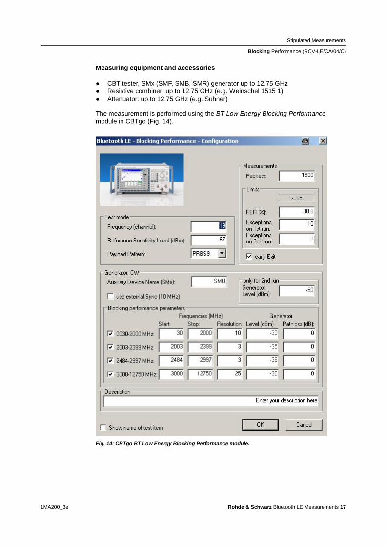
Stipulated Measurements
Blocking Performance (RCV-LECA04C)
1MA200_3e Rohde amp Schwarz Bluetooth LE Measurements 17
Measuring equipment and accessories
CBT tester SMx (SMF SMB SMR) generator up to 1275 GHz
Resistive combiner up to 1275 GHz (eg Weinschel 1515 1)
Attenuator up to 1275 GHz (eg Suhner) The measurement is performed using the BT Low Energy Blocking Performance module in CBTgo (Fig 14)
Fig 14 CBTgo BT Low Energy Blocking Performance module
Stipulated Measurements
Blocking Performance (RCV-LECA04C)
1MA200_3e Rohde amp Schwarz Bluetooth LE Measurements 18
Under Test mode you can select the test packet payload type The RX frequency of the measurement channel can be set The reference sensitivity level can be modified as required According to the specification this must be ndash67 dBm Under Generator CW the auxiliary device name is to be entered The name must be identical to that entered for Auxiliary GPIB Port x in the Configuration menu Moreover the path loss between the generator and the DUT can be set Under Blocking performance parameters the generator level as well as a start and a stop frequency can be entered in four columns In addition you can enter the measurement frequency resolution The default settings are the four ranges according to the specification (see Table 4) Under Measurements you can enter the PER limit the number of packets and the allowed exceptions for the two runs separately If Early Exit is enabled the measurement is exited if more then ten spurious frequencies are detected CBTgo automatically performs the test using the selected generator settings With the settings in compliance with the test specification the measurement time is at least 15 minutes (1 s per PER measurement times approx 890 interferer channels in the 1st test run) Fig 15 shows a typical entry in the test report
Stipulated Measurements
Blocking Performance (RCV-LECA04C)
1MA200_3e Rohde amp Schwarz Bluetooth LE Measurements 19
Fig 15 Blocking performance test report CBTgo shows the measurement results at the detected
spurious frequencies and a summary for the different sections The repeated measurements with
relaxed conditions are also shown
Stipulated Measurements
Intermodulation Performance (RCV-LECA05C)
1MA200_3e Rohde amp Schwarz Bluetooth LE Measurements 20
33 Intermodulation Performance (RCV-LECA05C)
This measurement verifies the intermodulation performance of the DUTs receiver A
PER measurement is performed using two interferers that cause intermodulation at the
DUTs receive frequency
The wanted signal is transmitted on a single channel in non-hopping mode A CW
interferer spaced +n MHz and a Bluetooth interferer spaced +2n MHz from the wanted
signal are generated coupled in and the PER is determined The measurement is
then performed with the interferers at ndashn MHz and ndash2n MHz The two measurements
are repeated on two more wanted channels (Fig 16)
Fig 16 Intermodulation performance For each of three channels the packet error rate in the
presence of a CW interferer in a distance n and in the presence of a Bluetooth interferer in a distance
2n is measured
The Bluetooth test specification defines the following settings
Hopping off (RX on single channel)
Three channels (0 19 39)
PRBS9
Wanted signal level at ndash64 dBm
n = 3 4 or 5 (defined by manufacturer)
Bluetooth interferer low energy GFSK with PRBS15 spaced plusmn2n MHz from wanted
signal level ndash50 dBm
CW interferer spaced plusmnn MHz from wanted signal level ndash50 dBm
1500 packets
Result
A PER of 308 must be obtained for each of the three channels
Stipulated Measurements
Intermodulation Performance (RCV-LECA05C)
1MA200_3e Rohde amp Schwarz Bluetooth LE Measurements 21
Test setup
The two interferer signals required in this measurement are supplied via two generator
paths that are combined via a hybrid combiner The resulting signal is coupled into the
line connecting the CBT and the DUT via a second hybrid combiner If a dual-channel
SMU is used one generator is sufficient (Fig 17) otherwise two generators are
required (Fig 18)
Fig 17 Test setup 1 for intermodulation performance measurement using one generator
Stipulated Measurements
Intermodulation Performance (RCV-LECA05C)
1MA200_3e Rohde amp Schwarz Bluetooth LE Measurements 22
Fig 18 Test setup 2 for intermodulation performance using two generators
Measuring equipment and accessories
CBT tester SMU or SMJ + SMF or SMB or SMR signal generators
Two hybrid combiners (eg Minicircuits ZFSC 2 2500)
The measurement is performed using the BT Low Energy Intermodulation
Performance module in CBTgo (Fig 19)
Stipulated Measurements
Intermodulation Performance (RCV-LECA05C)
1MA200_3e Rohde amp Schwarz Bluetooth LE Measurements 23
Fig 19 CBTgo BT Low Energy Intermodulation Performance module
Under Test Mode you can select the test packet payload type The RX frequencies of the three channels can be set The reference sensitivity level can be modified as required According to the specification this must be ndash 64 dBm
Under Generator 1 and Generator 2 the auxiliary device name is to be entered The
name must be identical to that entered for Auxiliary GPIB Port x in the Configuration
menu The intermodulation distance n (spacing from wanted signal) must be selected
Moreover the path loss between the generator and the DUT as well as the
interference level can be entered for each generator A second generator can be
included in the test setup if the first generator does not offer dual-channel capability
Stipulated Measurements
Intermodulation Performance (RCV-LECA05C)
1MA200_3e Rohde amp Schwarz Bluetooth LE Measurements 24
Under Measurements you can enter the PER limit and the number of packets The
default settings comply with the test specification
CBTgo automatically performs the test on the three channels using the selected
generator settings
Fig 20 shows a typical entry in the test report
Fig 20 Low energy intermodulation performance test report
Appendix
References
1MA200_3e Rohde amp Schwarz Bluetooth LE Measurements 25
4 Appendix
41 References
[1] Bluetooth Test amp Interoperability Working Group Bluetooth Low Energy RF PHY
Test Specification RF-PHYTS402 122012 Bluetooth SIG Inc
[2] Rohde amp Schwarz Manual for Windows Application CBTgo (V170)
[3] Rohde amp Schwarz Measurements on Bluetooth Products using
RampS CMU200CBT and CMUgoCBTgo Application Note 1CM50 102006
[4] Rohde amp Schwarz Bluetooth Measurements Using CBTgo Additional Tests Application Note 1MA106 022013
42 Additional Information
Please send your comments and suggestions regarding this application note to
TM-Applicationsrohde-schwarzcom
Visit the CBTgo website at
httpwww2rohde-
schwarzcomenproductstest_and_measurementmobile_radioCBT_CBT32-|-
Tools-|-67-|-1459html
or as a registered user in GLORIS the CMU Customer Web at
httpsextranetrohde-schwarzcom
Appendix
Ordering Information
1MA200_3e Rohde amp Schwarz Bluetooth LE Measurements 26
43 Ordering Information
Ordering information
Bluetooth tester
CBT Bluetooth tester with display 1153900035
CBT32 Bluetooth tester without display 1153900032
CBT-K57 Bluetooth Low Energy 1170410202
Vector signal generator
SMU200A Vector Signal Generator 1141200502
SMU-B9 Baseband Generator 128 Msample 1161076602
SMU-B10 Baseband Generator 64 Msample 1141700702
SMU-B11 Baseband Generator 16 Msample 1159841102
SMU-B13 Baseband Main Module 1141800304
SMU-B10x RF Path A
SMU-B20x RF Path B
SMW200A Vector Signal Generator 1412000002
SMW-B10 Baseband Generator with ARB
(64 Msample) and Digital Modulation
(realtime) 120 MHz RF bandwidth
1413120002
SMW-B13 Baseband Main Module one IQ path to RF 1413280702
SMW-B10x RF Path A
SMW-B20x RF Path B
SMBV100A Vector Signal Generator 1407600402
Signal generator
SMF100A Microwave Signal Generator
up to 435 GHz
1167000002
SMB100A RF and Microwave Signal Generator
up to 1275 GHz
1406600002
xx stands for the different frequency ranges (eg 1155500126 MHz to 26 GHz
Note Available options are not listed in detail
Please contact your local Rohde amp Schwarz sales office for further assistance
About Rohde amp Schwarz
Rohde amp Schwarz is an independent group
of companies specializing in electronics It is
a leading supplier of solutions in the fields of
test and measurement broadcasting
radiomonitoring and radiolocation as well as
secure communications Established more
than 75 years ago Rohde amp Schwarz has a
global presence and a dedicated service
network in over 70 countries Company
headquarters are in Munich Germany
Environmental commitment
Energy-efficient products
Continuous improvement in
environmental sustainability
ISO 14001-certified environmental
management system
Regional contact
Europe Africa Middle East
+49 89 4129 12345
customersupportrohde-schwarzcom North America
1-888-TEST-RSA (1-888-837-8772)
customersupportrsarohde-schwarzcom Latin America
+1-410-910-7988
customersupportlarohde-schwarzcom AsiaPacific
+65 65 13 04 88
customersupportasiarohde-schwarzcom
This application note and the supplied
programs may only be used subject to the
conditions of use set forth in the download
area of the Rohde amp Schwarz website
RampSreg is a registered trademark of Rohde amp Schwarz GmbH amp Co KG Trade names are trademarks of the owners
Rohde amp Schwarz GmbH amp Co KG
Muumlhldorfstraszlige 15 | D - 81671 Muumlnchen
Phone + 49 89 4129 - 0 | Fax + 49 89 4129 ndash 13777
wwwrohde-schwarzcom
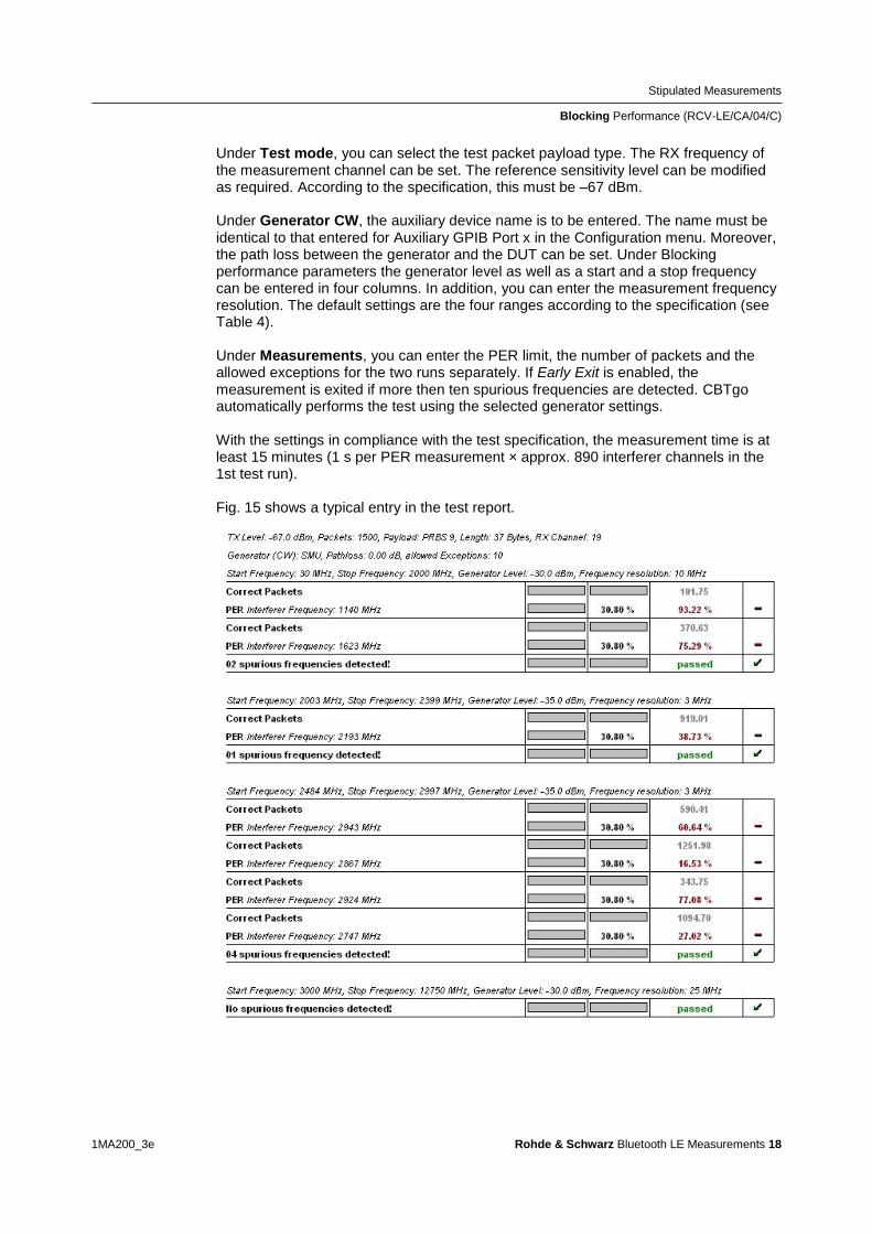
Stipulated Measurements
Blocking Performance (RCV-LECA04C)
1MA200_3e Rohde amp Schwarz Bluetooth LE Measurements 18
Under Test mode you can select the test packet payload type The RX frequency of the measurement channel can be set The reference sensitivity level can be modified as required According to the specification this must be ndash67 dBm Under Generator CW the auxiliary device name is to be entered The name must be identical to that entered for Auxiliary GPIB Port x in the Configuration menu Moreover the path loss between the generator and the DUT can be set Under Blocking performance parameters the generator level as well as a start and a stop frequency can be entered in four columns In addition you can enter the measurement frequency resolution The default settings are the four ranges according to the specification (see Table 4) Under Measurements you can enter the PER limit the number of packets and the allowed exceptions for the two runs separately If Early Exit is enabled the measurement is exited if more then ten spurious frequencies are detected CBTgo automatically performs the test using the selected generator settings With the settings in compliance with the test specification the measurement time is at least 15 minutes (1 s per PER measurement times approx 890 interferer channels in the 1st test run) Fig 15 shows a typical entry in the test report
Stipulated Measurements
Blocking Performance (RCV-LECA04C)
1MA200_3e Rohde amp Schwarz Bluetooth LE Measurements 19
Fig 15 Blocking performance test report CBTgo shows the measurement results at the detected
spurious frequencies and a summary for the different sections The repeated measurements with
relaxed conditions are also shown
Stipulated Measurements
Intermodulation Performance (RCV-LECA05C)
1MA200_3e Rohde amp Schwarz Bluetooth LE Measurements 20
33 Intermodulation Performance (RCV-LECA05C)
This measurement verifies the intermodulation performance of the DUTs receiver A
PER measurement is performed using two interferers that cause intermodulation at the
DUTs receive frequency
The wanted signal is transmitted on a single channel in non-hopping mode A CW
interferer spaced +n MHz and a Bluetooth interferer spaced +2n MHz from the wanted
signal are generated coupled in and the PER is determined The measurement is
then performed with the interferers at ndashn MHz and ndash2n MHz The two measurements
are repeated on two more wanted channels (Fig 16)
Fig 16 Intermodulation performance For each of three channels the packet error rate in the
presence of a CW interferer in a distance n and in the presence of a Bluetooth interferer in a distance
2n is measured
The Bluetooth test specification defines the following settings
Hopping off (RX on single channel)
Three channels (0 19 39)
PRBS9
Wanted signal level at ndash64 dBm
n = 3 4 or 5 (defined by manufacturer)
Bluetooth interferer low energy GFSK with PRBS15 spaced plusmn2n MHz from wanted
signal level ndash50 dBm
CW interferer spaced plusmnn MHz from wanted signal level ndash50 dBm
1500 packets
Result
A PER of 308 must be obtained for each of the three channels
Stipulated Measurements
Intermodulation Performance (RCV-LECA05C)
1MA200_3e Rohde amp Schwarz Bluetooth LE Measurements 21
Test setup
The two interferer signals required in this measurement are supplied via two generator
paths that are combined via a hybrid combiner The resulting signal is coupled into the
line connecting the CBT and the DUT via a second hybrid combiner If a dual-channel
SMU is used one generator is sufficient (Fig 17) otherwise two generators are
required (Fig 18)
Fig 17 Test setup 1 for intermodulation performance measurement using one generator
Stipulated Measurements
Intermodulation Performance (RCV-LECA05C)
1MA200_3e Rohde amp Schwarz Bluetooth LE Measurements 22
Fig 18 Test setup 2 for intermodulation performance using two generators
Measuring equipment and accessories
CBT tester SMU or SMJ + SMF or SMB or SMR signal generators
Two hybrid combiners (eg Minicircuits ZFSC 2 2500)
The measurement is performed using the BT Low Energy Intermodulation
Performance module in CBTgo (Fig 19)
Stipulated Measurements
Intermodulation Performance (RCV-LECA05C)
1MA200_3e Rohde amp Schwarz Bluetooth LE Measurements 23
Fig 19 CBTgo BT Low Energy Intermodulation Performance module
Under Test Mode you can select the test packet payload type The RX frequencies of the three channels can be set The reference sensitivity level can be modified as required According to the specification this must be ndash 64 dBm
Under Generator 1 and Generator 2 the auxiliary device name is to be entered The
name must be identical to that entered for Auxiliary GPIB Port x in the Configuration
menu The intermodulation distance n (spacing from wanted signal) must be selected
Moreover the path loss between the generator and the DUT as well as the
interference level can be entered for each generator A second generator can be
included in the test setup if the first generator does not offer dual-channel capability
Stipulated Measurements
Intermodulation Performance (RCV-LECA05C)
1MA200_3e Rohde amp Schwarz Bluetooth LE Measurements 24
Under Measurements you can enter the PER limit and the number of packets The
default settings comply with the test specification
CBTgo automatically performs the test on the three channels using the selected
generator settings
Fig 20 shows a typical entry in the test report
Fig 20 Low energy intermodulation performance test report
Appendix
References
1MA200_3e Rohde amp Schwarz Bluetooth LE Measurements 25
4 Appendix
41 References
[1] Bluetooth Test amp Interoperability Working Group Bluetooth Low Energy RF PHY
Test Specification RF-PHYTS402 122012 Bluetooth SIG Inc
[2] Rohde amp Schwarz Manual for Windows Application CBTgo (V170)
[3] Rohde amp Schwarz Measurements on Bluetooth Products using
RampS CMU200CBT and CMUgoCBTgo Application Note 1CM50 102006
[4] Rohde amp Schwarz Bluetooth Measurements Using CBTgo Additional Tests Application Note 1MA106 022013
42 Additional Information
Please send your comments and suggestions regarding this application note to
TM-Applicationsrohde-schwarzcom
Visit the CBTgo website at
httpwww2rohde-
schwarzcomenproductstest_and_measurementmobile_radioCBT_CBT32-|-
Tools-|-67-|-1459html
or as a registered user in GLORIS the CMU Customer Web at
httpsextranetrohde-schwarzcom
Appendix
Ordering Information
1MA200_3e Rohde amp Schwarz Bluetooth LE Measurements 26
43 Ordering Information
Ordering information
Bluetooth tester
CBT Bluetooth tester with display 1153900035
CBT32 Bluetooth tester without display 1153900032
CBT-K57 Bluetooth Low Energy 1170410202
Vector signal generator
SMU200A Vector Signal Generator 1141200502
SMU-B9 Baseband Generator 128 Msample 1161076602
SMU-B10 Baseband Generator 64 Msample 1141700702
SMU-B11 Baseband Generator 16 Msample 1159841102
SMU-B13 Baseband Main Module 1141800304
SMU-B10x RF Path A
SMU-B20x RF Path B
SMW200A Vector Signal Generator 1412000002
SMW-B10 Baseband Generator with ARB
(64 Msample) and Digital Modulation
(realtime) 120 MHz RF bandwidth
1413120002
SMW-B13 Baseband Main Module one IQ path to RF 1413280702
SMW-B10x RF Path A
SMW-B20x RF Path B
SMBV100A Vector Signal Generator 1407600402
Signal generator
SMF100A Microwave Signal Generator
up to 435 GHz
1167000002
SMB100A RF and Microwave Signal Generator
up to 1275 GHz
1406600002
xx stands for the different frequency ranges (eg 1155500126 MHz to 26 GHz
Note Available options are not listed in detail
Please contact your local Rohde amp Schwarz sales office for further assistance
About Rohde amp Schwarz
Rohde amp Schwarz is an independent group
of companies specializing in electronics It is
a leading supplier of solutions in the fields of
test and measurement broadcasting
radiomonitoring and radiolocation as well as
secure communications Established more
than 75 years ago Rohde amp Schwarz has a
global presence and a dedicated service
network in over 70 countries Company
headquarters are in Munich Germany
Environmental commitment
Energy-efficient products
Continuous improvement in
environmental sustainability
ISO 14001-certified environmental
management system
Regional contact
Europe Africa Middle East
+49 89 4129 12345
customersupportrohde-schwarzcom North America
1-888-TEST-RSA (1-888-837-8772)
customersupportrsarohde-schwarzcom Latin America
+1-410-910-7988
customersupportlarohde-schwarzcom AsiaPacific
+65 65 13 04 88
customersupportasiarohde-schwarzcom
This application note and the supplied
programs may only be used subject to the
conditions of use set forth in the download
area of the Rohde amp Schwarz website
RampSreg is a registered trademark of Rohde amp Schwarz GmbH amp Co KG Trade names are trademarks of the owners
Rohde amp Schwarz GmbH amp Co KG
Muumlhldorfstraszlige 15 | D - 81671 Muumlnchen
Phone + 49 89 4129 - 0 | Fax + 49 89 4129 ndash 13777
wwwrohde-schwarzcom
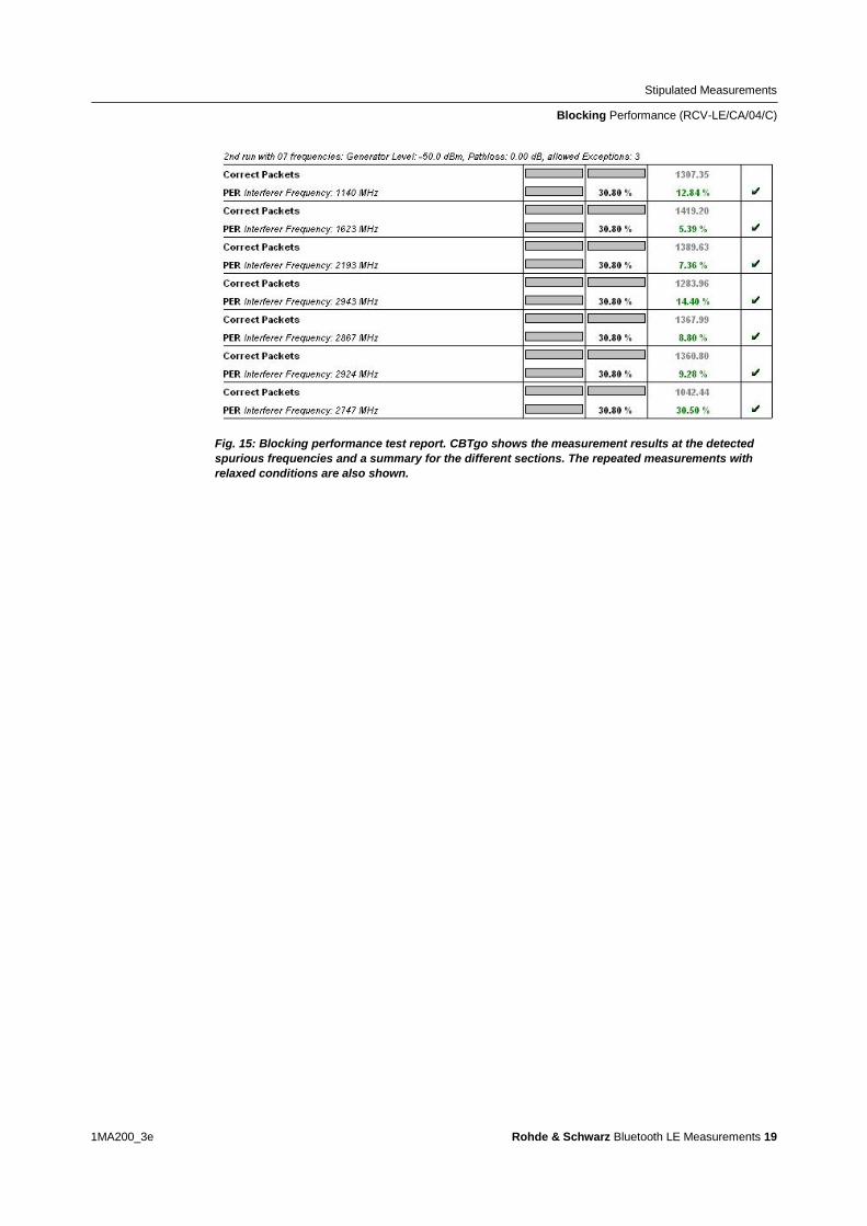
Stipulated Measurements
Blocking Performance (RCV-LECA04C)
1MA200_3e Rohde amp Schwarz Bluetooth LE Measurements 19
Fig 15 Blocking performance test report CBTgo shows the measurement results at the detected
spurious frequencies and a summary for the different sections The repeated measurements with
relaxed conditions are also shown
Stipulated Measurements
Intermodulation Performance (RCV-LECA05C)
1MA200_3e Rohde amp Schwarz Bluetooth LE Measurements 20
33 Intermodulation Performance (RCV-LECA05C)
This measurement verifies the intermodulation performance of the DUTs receiver A
PER measurement is performed using two interferers that cause intermodulation at the
DUTs receive frequency
The wanted signal is transmitted on a single channel in non-hopping mode A CW
interferer spaced +n MHz and a Bluetooth interferer spaced +2n MHz from the wanted
signal are generated coupled in and the PER is determined The measurement is
then performed with the interferers at ndashn MHz and ndash2n MHz The two measurements
are repeated on two more wanted channels (Fig 16)
Fig 16 Intermodulation performance For each of three channels the packet error rate in the
presence of a CW interferer in a distance n and in the presence of a Bluetooth interferer in a distance
2n is measured
The Bluetooth test specification defines the following settings
Hopping off (RX on single channel)
Three channels (0 19 39)
PRBS9
Wanted signal level at ndash64 dBm
n = 3 4 or 5 (defined by manufacturer)
Bluetooth interferer low energy GFSK with PRBS15 spaced plusmn2n MHz from wanted
signal level ndash50 dBm
CW interferer spaced plusmnn MHz from wanted signal level ndash50 dBm
1500 packets
Result
A PER of 308 must be obtained for each of the three channels
Stipulated Measurements
Intermodulation Performance (RCV-LECA05C)
1MA200_3e Rohde amp Schwarz Bluetooth LE Measurements 21
Test setup
The two interferer signals required in this measurement are supplied via two generator
paths that are combined via a hybrid combiner The resulting signal is coupled into the
line connecting the CBT and the DUT via a second hybrid combiner If a dual-channel
SMU is used one generator is sufficient (Fig 17) otherwise two generators are
required (Fig 18)
Fig 17 Test setup 1 for intermodulation performance measurement using one generator
Stipulated Measurements
Intermodulation Performance (RCV-LECA05C)
1MA200_3e Rohde amp Schwarz Bluetooth LE Measurements 22
Fig 18 Test setup 2 for intermodulation performance using two generators
Measuring equipment and accessories
CBT tester SMU or SMJ + SMF or SMB or SMR signal generators
Two hybrid combiners (eg Minicircuits ZFSC 2 2500)
The measurement is performed using the BT Low Energy Intermodulation
Performance module in CBTgo (Fig 19)
Stipulated Measurements
Intermodulation Performance (RCV-LECA05C)
1MA200_3e Rohde amp Schwarz Bluetooth LE Measurements 23
Fig 19 CBTgo BT Low Energy Intermodulation Performance module
Under Test Mode you can select the test packet payload type The RX frequencies of the three channels can be set The reference sensitivity level can be modified as required According to the specification this must be ndash 64 dBm
Under Generator 1 and Generator 2 the auxiliary device name is to be entered The
name must be identical to that entered for Auxiliary GPIB Port x in the Configuration
menu The intermodulation distance n (spacing from wanted signal) must be selected
Moreover the path loss between the generator and the DUT as well as the
interference level can be entered for each generator A second generator can be
included in the test setup if the first generator does not offer dual-channel capability
Stipulated Measurements
Intermodulation Performance (RCV-LECA05C)
1MA200_3e Rohde amp Schwarz Bluetooth LE Measurements 24
Under Measurements you can enter the PER limit and the number of packets The
default settings comply with the test specification
CBTgo automatically performs the test on the three channels using the selected
generator settings
Fig 20 shows a typical entry in the test report
Fig 20 Low energy intermodulation performance test report
Appendix
References
1MA200_3e Rohde amp Schwarz Bluetooth LE Measurements 25
4 Appendix
41 References
[1] Bluetooth Test amp Interoperability Working Group Bluetooth Low Energy RF PHY
Test Specification RF-PHYTS402 122012 Bluetooth SIG Inc
[2] Rohde amp Schwarz Manual for Windows Application CBTgo (V170)
[3] Rohde amp Schwarz Measurements on Bluetooth Products using
RampS CMU200CBT and CMUgoCBTgo Application Note 1CM50 102006
[4] Rohde amp Schwarz Bluetooth Measurements Using CBTgo Additional Tests Application Note 1MA106 022013
42 Additional Information
Please send your comments and suggestions regarding this application note to
TM-Applicationsrohde-schwarzcom
Visit the CBTgo website at
httpwww2rohde-
schwarzcomenproductstest_and_measurementmobile_radioCBT_CBT32-|-
Tools-|-67-|-1459html
or as a registered user in GLORIS the CMU Customer Web at
httpsextranetrohde-schwarzcom
Appendix
Ordering Information
1MA200_3e Rohde amp Schwarz Bluetooth LE Measurements 26
43 Ordering Information
Ordering information
Bluetooth tester
CBT Bluetooth tester with display 1153900035
CBT32 Bluetooth tester without display 1153900032
CBT-K57 Bluetooth Low Energy 1170410202
Vector signal generator
SMU200A Vector Signal Generator 1141200502
SMU-B9 Baseband Generator 128 Msample 1161076602
SMU-B10 Baseband Generator 64 Msample 1141700702
SMU-B11 Baseband Generator 16 Msample 1159841102
SMU-B13 Baseband Main Module 1141800304
SMU-B10x RF Path A
SMU-B20x RF Path B
SMW200A Vector Signal Generator 1412000002
SMW-B10 Baseband Generator with ARB
(64 Msample) and Digital Modulation
(realtime) 120 MHz RF bandwidth
1413120002
SMW-B13 Baseband Main Module one IQ path to RF 1413280702
SMW-B10x RF Path A
SMW-B20x RF Path B
SMBV100A Vector Signal Generator 1407600402
Signal generator
SMF100A Microwave Signal Generator
up to 435 GHz
1167000002
SMB100A RF and Microwave Signal Generator
up to 1275 GHz
1406600002
xx stands for the different frequency ranges (eg 1155500126 MHz to 26 GHz
Note Available options are not listed in detail
Please contact your local Rohde amp Schwarz sales office for further assistance
About Rohde amp Schwarz
Rohde amp Schwarz is an independent group
of companies specializing in electronics It is
a leading supplier of solutions in the fields of
test and measurement broadcasting
radiomonitoring and radiolocation as well as
secure communications Established more
than 75 years ago Rohde amp Schwarz has a
global presence and a dedicated service
network in over 70 countries Company
headquarters are in Munich Germany
Environmental commitment
Energy-efficient products
Continuous improvement in
environmental sustainability
ISO 14001-certified environmental
management system
Regional contact
Europe Africa Middle East
+49 89 4129 12345
customersupportrohde-schwarzcom North America
1-888-TEST-RSA (1-888-837-8772)
customersupportrsarohde-schwarzcom Latin America
+1-410-910-7988
customersupportlarohde-schwarzcom AsiaPacific
+65 65 13 04 88
customersupportasiarohde-schwarzcom
This application note and the supplied
programs may only be used subject to the
conditions of use set forth in the download
area of the Rohde amp Schwarz website
RampSreg is a registered trademark of Rohde amp Schwarz GmbH amp Co KG Trade names are trademarks of the owners
Rohde amp Schwarz GmbH amp Co KG
Muumlhldorfstraszlige 15 | D - 81671 Muumlnchen
Phone + 49 89 4129 - 0 | Fax + 49 89 4129 ndash 13777
wwwrohde-schwarzcom

Stipulated Measurements
Intermodulation Performance (RCV-LECA05C)
1MA200_3e Rohde amp Schwarz Bluetooth LE Measurements 20
33 Intermodulation Performance (RCV-LECA05C)
This measurement verifies the intermodulation performance of the DUTs receiver A
PER measurement is performed using two interferers that cause intermodulation at the
DUTs receive frequency
The wanted signal is transmitted on a single channel in non-hopping mode A CW
interferer spaced +n MHz and a Bluetooth interferer spaced +2n MHz from the wanted
signal are generated coupled in and the PER is determined The measurement is
then performed with the interferers at ndashn MHz and ndash2n MHz The two measurements
are repeated on two more wanted channels (Fig 16)
Fig 16 Intermodulation performance For each of three channels the packet error rate in the
presence of a CW interferer in a distance n and in the presence of a Bluetooth interferer in a distance
2n is measured
The Bluetooth test specification defines the following settings
Hopping off (RX on single channel)
Three channels (0 19 39)
PRBS9
Wanted signal level at ndash64 dBm
n = 3 4 or 5 (defined by manufacturer)
Bluetooth interferer low energy GFSK with PRBS15 spaced plusmn2n MHz from wanted
signal level ndash50 dBm
CW interferer spaced plusmnn MHz from wanted signal level ndash50 dBm
1500 packets
Result
A PER of 308 must be obtained for each of the three channels
Stipulated Measurements
Intermodulation Performance (RCV-LECA05C)
1MA200_3e Rohde amp Schwarz Bluetooth LE Measurements 21
Test setup
The two interferer signals required in this measurement are supplied via two generator
paths that are combined via a hybrid combiner The resulting signal is coupled into the
line connecting the CBT and the DUT via a second hybrid combiner If a dual-channel
SMU is used one generator is sufficient (Fig 17) otherwise two generators are
required (Fig 18)
Fig 17 Test setup 1 for intermodulation performance measurement using one generator
Stipulated Measurements
Intermodulation Performance (RCV-LECA05C)
1MA200_3e Rohde amp Schwarz Bluetooth LE Measurements 22
Fig 18 Test setup 2 for intermodulation performance using two generators
Measuring equipment and accessories
CBT tester SMU or SMJ + SMF or SMB or SMR signal generators
Two hybrid combiners (eg Minicircuits ZFSC 2 2500)
The measurement is performed using the BT Low Energy Intermodulation
Performance module in CBTgo (Fig 19)
Stipulated Measurements
Intermodulation Performance (RCV-LECA05C)
1MA200_3e Rohde amp Schwarz Bluetooth LE Measurements 23
Fig 19 CBTgo BT Low Energy Intermodulation Performance module
Under Test Mode you can select the test packet payload type The RX frequencies of the three channels can be set The reference sensitivity level can be modified as required According to the specification this must be ndash 64 dBm
Under Generator 1 and Generator 2 the auxiliary device name is to be entered The
name must be identical to that entered for Auxiliary GPIB Port x in the Configuration
menu The intermodulation distance n (spacing from wanted signal) must be selected
Moreover the path loss between the generator and the DUT as well as the
interference level can be entered for each generator A second generator can be
included in the test setup if the first generator does not offer dual-channel capability
Stipulated Measurements
Intermodulation Performance (RCV-LECA05C)
1MA200_3e Rohde amp Schwarz Bluetooth LE Measurements 24
Under Measurements you can enter the PER limit and the number of packets The
default settings comply with the test specification
CBTgo automatically performs the test on the three channels using the selected
generator settings
Fig 20 shows a typical entry in the test report
Fig 20 Low energy intermodulation performance test report
Appendix
References
1MA200_3e Rohde amp Schwarz Bluetooth LE Measurements 25
4 Appendix
41 References
[1] Bluetooth Test amp Interoperability Working Group Bluetooth Low Energy RF PHY
Test Specification RF-PHYTS402 122012 Bluetooth SIG Inc
[2] Rohde amp Schwarz Manual for Windows Application CBTgo (V170)
[3] Rohde amp Schwarz Measurements on Bluetooth Products using
RampS CMU200CBT and CMUgoCBTgo Application Note 1CM50 102006
[4] Rohde amp Schwarz Bluetooth Measurements Using CBTgo Additional Tests Application Note 1MA106 022013
42 Additional Information
Please send your comments and suggestions regarding this application note to
TM-Applicationsrohde-schwarzcom
Visit the CBTgo website at
httpwww2rohde-
schwarzcomenproductstest_and_measurementmobile_radioCBT_CBT32-|-
Tools-|-67-|-1459html
or as a registered user in GLORIS the CMU Customer Web at
httpsextranetrohde-schwarzcom
Appendix
Ordering Information
1MA200_3e Rohde amp Schwarz Bluetooth LE Measurements 26
43 Ordering Information
Ordering information
Bluetooth tester
CBT Bluetooth tester with display 1153900035
CBT32 Bluetooth tester without display 1153900032
CBT-K57 Bluetooth Low Energy 1170410202
Vector signal generator
SMU200A Vector Signal Generator 1141200502
SMU-B9 Baseband Generator 128 Msample 1161076602
SMU-B10 Baseband Generator 64 Msample 1141700702
SMU-B11 Baseband Generator 16 Msample 1159841102
SMU-B13 Baseband Main Module 1141800304
SMU-B10x RF Path A
SMU-B20x RF Path B
SMW200A Vector Signal Generator 1412000002
SMW-B10 Baseband Generator with ARB
(64 Msample) and Digital Modulation
(realtime) 120 MHz RF bandwidth
1413120002
SMW-B13 Baseband Main Module one IQ path to RF 1413280702
SMW-B10x RF Path A
SMW-B20x RF Path B
SMBV100A Vector Signal Generator 1407600402
Signal generator
SMF100A Microwave Signal Generator
up to 435 GHz
1167000002
SMB100A RF and Microwave Signal Generator
up to 1275 GHz
1406600002
xx stands for the different frequency ranges (eg 1155500126 MHz to 26 GHz
Note Available options are not listed in detail
Please contact your local Rohde amp Schwarz sales office for further assistance
About Rohde amp Schwarz
Rohde amp Schwarz is an independent group
of companies specializing in electronics It is
a leading supplier of solutions in the fields of
test and measurement broadcasting
radiomonitoring and radiolocation as well as
secure communications Established more
than 75 years ago Rohde amp Schwarz has a
global presence and a dedicated service
network in over 70 countries Company
headquarters are in Munich Germany
Environmental commitment
Energy-efficient products
Continuous improvement in
environmental sustainability
ISO 14001-certified environmental
management system
Regional contact
Europe Africa Middle East
+49 89 4129 12345
customersupportrohde-schwarzcom North America
1-888-TEST-RSA (1-888-837-8772)
customersupportrsarohde-schwarzcom Latin America
+1-410-910-7988
customersupportlarohde-schwarzcom AsiaPacific
+65 65 13 04 88
customersupportasiarohde-schwarzcom
This application note and the supplied
programs may only be used subject to the
conditions of use set forth in the download
area of the Rohde amp Schwarz website
RampSreg is a registered trademark of Rohde amp Schwarz GmbH amp Co KG Trade names are trademarks of the owners
Rohde amp Schwarz GmbH amp Co KG
Muumlhldorfstraszlige 15 | D - 81671 Muumlnchen
Phone + 49 89 4129 - 0 | Fax + 49 89 4129 ndash 13777
wwwrohde-schwarzcom
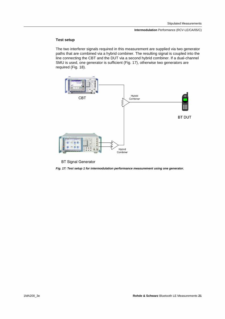
Stipulated Measurements
Intermodulation Performance (RCV-LECA05C)
1MA200_3e Rohde amp Schwarz Bluetooth LE Measurements 21
Test setup
The two interferer signals required in this measurement are supplied via two generator
paths that are combined via a hybrid combiner The resulting signal is coupled into the
line connecting the CBT and the DUT via a second hybrid combiner If a dual-channel
SMU is used one generator is sufficient (Fig 17) otherwise two generators are
required (Fig 18)
Fig 17 Test setup 1 for intermodulation performance measurement using one generator
Stipulated Measurements
Intermodulation Performance (RCV-LECA05C)
1MA200_3e Rohde amp Schwarz Bluetooth LE Measurements 22
Fig 18 Test setup 2 for intermodulation performance using two generators
Measuring equipment and accessories
CBT tester SMU or SMJ + SMF or SMB or SMR signal generators
Two hybrid combiners (eg Minicircuits ZFSC 2 2500)
The measurement is performed using the BT Low Energy Intermodulation
Performance module in CBTgo (Fig 19)
Stipulated Measurements
Intermodulation Performance (RCV-LECA05C)
1MA200_3e Rohde amp Schwarz Bluetooth LE Measurements 23
Fig 19 CBTgo BT Low Energy Intermodulation Performance module
Under Test Mode you can select the test packet payload type The RX frequencies of the three channels can be set The reference sensitivity level can be modified as required According to the specification this must be ndash 64 dBm
Under Generator 1 and Generator 2 the auxiliary device name is to be entered The
name must be identical to that entered for Auxiliary GPIB Port x in the Configuration
menu The intermodulation distance n (spacing from wanted signal) must be selected
Moreover the path loss between the generator and the DUT as well as the
interference level can be entered for each generator A second generator can be
included in the test setup if the first generator does not offer dual-channel capability
Stipulated Measurements
Intermodulation Performance (RCV-LECA05C)
1MA200_3e Rohde amp Schwarz Bluetooth LE Measurements 24
Under Measurements you can enter the PER limit and the number of packets The
default settings comply with the test specification
CBTgo automatically performs the test on the three channels using the selected
generator settings
Fig 20 shows a typical entry in the test report
Fig 20 Low energy intermodulation performance test report
Appendix
References
1MA200_3e Rohde amp Schwarz Bluetooth LE Measurements 25
4 Appendix
41 References
[1] Bluetooth Test amp Interoperability Working Group Bluetooth Low Energy RF PHY
Test Specification RF-PHYTS402 122012 Bluetooth SIG Inc
[2] Rohde amp Schwarz Manual for Windows Application CBTgo (V170)
[3] Rohde amp Schwarz Measurements on Bluetooth Products using
RampS CMU200CBT and CMUgoCBTgo Application Note 1CM50 102006
[4] Rohde amp Schwarz Bluetooth Measurements Using CBTgo Additional Tests Application Note 1MA106 022013
42 Additional Information
Please send your comments and suggestions regarding this application note to
TM-Applicationsrohde-schwarzcom
Visit the CBTgo website at
httpwww2rohde-
schwarzcomenproductstest_and_measurementmobile_radioCBT_CBT32-|-
Tools-|-67-|-1459html
or as a registered user in GLORIS the CMU Customer Web at
httpsextranetrohde-schwarzcom
Appendix
Ordering Information
1MA200_3e Rohde amp Schwarz Bluetooth LE Measurements 26
43 Ordering Information
Ordering information
Bluetooth tester
CBT Bluetooth tester with display 1153900035
CBT32 Bluetooth tester without display 1153900032
CBT-K57 Bluetooth Low Energy 1170410202
Vector signal generator
SMU200A Vector Signal Generator 1141200502
SMU-B9 Baseband Generator 128 Msample 1161076602
SMU-B10 Baseband Generator 64 Msample 1141700702
SMU-B11 Baseband Generator 16 Msample 1159841102
SMU-B13 Baseband Main Module 1141800304
SMU-B10x RF Path A
SMU-B20x RF Path B
SMW200A Vector Signal Generator 1412000002
SMW-B10 Baseband Generator with ARB
(64 Msample) and Digital Modulation
(realtime) 120 MHz RF bandwidth
1413120002
SMW-B13 Baseband Main Module one IQ path to RF 1413280702
SMW-B10x RF Path A
SMW-B20x RF Path B
SMBV100A Vector Signal Generator 1407600402
Signal generator
SMF100A Microwave Signal Generator
up to 435 GHz
1167000002
SMB100A RF and Microwave Signal Generator
up to 1275 GHz
1406600002
xx stands for the different frequency ranges (eg 1155500126 MHz to 26 GHz
Note Available options are not listed in detail
Please contact your local Rohde amp Schwarz sales office for further assistance
About Rohde amp Schwarz
Rohde amp Schwarz is an independent group
of companies specializing in electronics It is
a leading supplier of solutions in the fields of
test and measurement broadcasting
radiomonitoring and radiolocation as well as
secure communications Established more
than 75 years ago Rohde amp Schwarz has a
global presence and a dedicated service
network in over 70 countries Company
headquarters are in Munich Germany
Environmental commitment
Energy-efficient products
Continuous improvement in
environmental sustainability
ISO 14001-certified environmental
management system
Regional contact
Europe Africa Middle East
+49 89 4129 12345
customersupportrohde-schwarzcom North America
1-888-TEST-RSA (1-888-837-8772)
customersupportrsarohde-schwarzcom Latin America
+1-410-910-7988
customersupportlarohde-schwarzcom AsiaPacific
+65 65 13 04 88
customersupportasiarohde-schwarzcom
This application note and the supplied
programs may only be used subject to the
conditions of use set forth in the download
area of the Rohde amp Schwarz website
RampSreg is a registered trademark of Rohde amp Schwarz GmbH amp Co KG Trade names are trademarks of the owners
Rohde amp Schwarz GmbH amp Co KG
Muumlhldorfstraszlige 15 | D - 81671 Muumlnchen
Phone + 49 89 4129 - 0 | Fax + 49 89 4129 ndash 13777
wwwrohde-schwarzcom
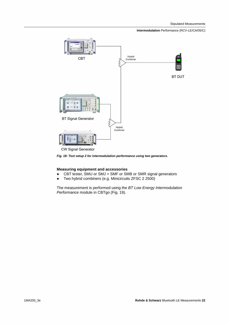
Stipulated Measurements
Intermodulation Performance (RCV-LECA05C)
1MA200_3e Rohde amp Schwarz Bluetooth LE Measurements 22
Fig 18 Test setup 2 for intermodulation performance using two generators
Measuring equipment and accessories
CBT tester SMU or SMJ + SMF or SMB or SMR signal generators
Two hybrid combiners (eg Minicircuits ZFSC 2 2500)
The measurement is performed using the BT Low Energy Intermodulation
Performance module in CBTgo (Fig 19)
Stipulated Measurements
Intermodulation Performance (RCV-LECA05C)
1MA200_3e Rohde amp Schwarz Bluetooth LE Measurements 23
Fig 19 CBTgo BT Low Energy Intermodulation Performance module
Under Test Mode you can select the test packet payload type The RX frequencies of the three channels can be set The reference sensitivity level can be modified as required According to the specification this must be ndash 64 dBm
Under Generator 1 and Generator 2 the auxiliary device name is to be entered The
name must be identical to that entered for Auxiliary GPIB Port x in the Configuration
menu The intermodulation distance n (spacing from wanted signal) must be selected
Moreover the path loss between the generator and the DUT as well as the
interference level can be entered for each generator A second generator can be
included in the test setup if the first generator does not offer dual-channel capability
Stipulated Measurements
Intermodulation Performance (RCV-LECA05C)
1MA200_3e Rohde amp Schwarz Bluetooth LE Measurements 24
Under Measurements you can enter the PER limit and the number of packets The
default settings comply with the test specification
CBTgo automatically performs the test on the three channels using the selected
generator settings
Fig 20 shows a typical entry in the test report
Fig 20 Low energy intermodulation performance test report
Appendix
References
1MA200_3e Rohde amp Schwarz Bluetooth LE Measurements 25
4 Appendix
41 References
[1] Bluetooth Test amp Interoperability Working Group Bluetooth Low Energy RF PHY
Test Specification RF-PHYTS402 122012 Bluetooth SIG Inc
[2] Rohde amp Schwarz Manual for Windows Application CBTgo (V170)
[3] Rohde amp Schwarz Measurements on Bluetooth Products using
RampS CMU200CBT and CMUgoCBTgo Application Note 1CM50 102006
[4] Rohde amp Schwarz Bluetooth Measurements Using CBTgo Additional Tests Application Note 1MA106 022013
42 Additional Information
Please send your comments and suggestions regarding this application note to
TM-Applicationsrohde-schwarzcom
Visit the CBTgo website at
httpwww2rohde-
schwarzcomenproductstest_and_measurementmobile_radioCBT_CBT32-|-
Tools-|-67-|-1459html
or as a registered user in GLORIS the CMU Customer Web at
httpsextranetrohde-schwarzcom
Appendix
Ordering Information
1MA200_3e Rohde amp Schwarz Bluetooth LE Measurements 26
43 Ordering Information
Ordering information
Bluetooth tester
CBT Bluetooth tester with display 1153900035
CBT32 Bluetooth tester without display 1153900032
CBT-K57 Bluetooth Low Energy 1170410202
Vector signal generator
SMU200A Vector Signal Generator 1141200502
SMU-B9 Baseband Generator 128 Msample 1161076602
SMU-B10 Baseband Generator 64 Msample 1141700702
SMU-B11 Baseband Generator 16 Msample 1159841102
SMU-B13 Baseband Main Module 1141800304
SMU-B10x RF Path A
SMU-B20x RF Path B
SMW200A Vector Signal Generator 1412000002
SMW-B10 Baseband Generator with ARB
(64 Msample) and Digital Modulation
(realtime) 120 MHz RF bandwidth
1413120002
SMW-B13 Baseband Main Module one IQ path to RF 1413280702
SMW-B10x RF Path A
SMW-B20x RF Path B
SMBV100A Vector Signal Generator 1407600402
Signal generator
SMF100A Microwave Signal Generator
up to 435 GHz
1167000002
SMB100A RF and Microwave Signal Generator
up to 1275 GHz
1406600002
xx stands for the different frequency ranges (eg 1155500126 MHz to 26 GHz
Note Available options are not listed in detail
Please contact your local Rohde amp Schwarz sales office for further assistance
About Rohde amp Schwarz
Rohde amp Schwarz is an independent group
of companies specializing in electronics It is
a leading supplier of solutions in the fields of
test and measurement broadcasting
radiomonitoring and radiolocation as well as
secure communications Established more
than 75 years ago Rohde amp Schwarz has a
global presence and a dedicated service
network in over 70 countries Company
headquarters are in Munich Germany
Environmental commitment
Energy-efficient products
Continuous improvement in
environmental sustainability
ISO 14001-certified environmental
management system
Regional contact
Europe Africa Middle East
+49 89 4129 12345
customersupportrohde-schwarzcom North America
1-888-TEST-RSA (1-888-837-8772)
customersupportrsarohde-schwarzcom Latin America
+1-410-910-7988
customersupportlarohde-schwarzcom AsiaPacific
+65 65 13 04 88
customersupportasiarohde-schwarzcom
This application note and the supplied
programs may only be used subject to the
conditions of use set forth in the download
area of the Rohde amp Schwarz website
RampSreg is a registered trademark of Rohde amp Schwarz GmbH amp Co KG Trade names are trademarks of the owners
Rohde amp Schwarz GmbH amp Co KG
Muumlhldorfstraszlige 15 | D - 81671 Muumlnchen
Phone + 49 89 4129 - 0 | Fax + 49 89 4129 ndash 13777
wwwrohde-schwarzcom
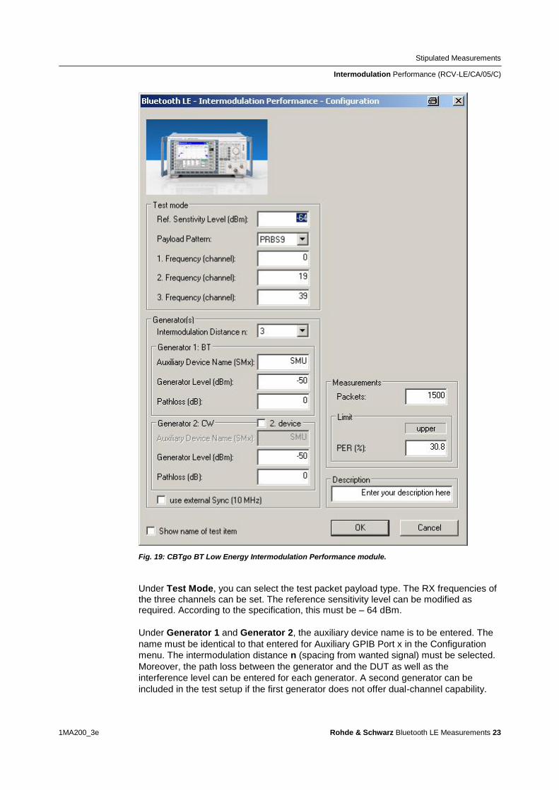
Stipulated Measurements
Intermodulation Performance (RCV-LECA05C)
1MA200_3e Rohde amp Schwarz Bluetooth LE Measurements 23
Fig 19 CBTgo BT Low Energy Intermodulation Performance module
Under Test Mode you can select the test packet payload type The RX frequencies of the three channels can be set The reference sensitivity level can be modified as required According to the specification this must be ndash 64 dBm
Under Generator 1 and Generator 2 the auxiliary device name is to be entered The
name must be identical to that entered for Auxiliary GPIB Port x in the Configuration
menu The intermodulation distance n (spacing from wanted signal) must be selected
Moreover the path loss between the generator and the DUT as well as the
interference level can be entered for each generator A second generator can be
included in the test setup if the first generator does not offer dual-channel capability
Stipulated Measurements
Intermodulation Performance (RCV-LECA05C)
1MA200_3e Rohde amp Schwarz Bluetooth LE Measurements 24
Under Measurements you can enter the PER limit and the number of packets The
default settings comply with the test specification
CBTgo automatically performs the test on the three channels using the selected
generator settings
Fig 20 shows a typical entry in the test report
Fig 20 Low energy intermodulation performance test report
Appendix
References
1MA200_3e Rohde amp Schwarz Bluetooth LE Measurements 25
4 Appendix
41 References
[1] Bluetooth Test amp Interoperability Working Group Bluetooth Low Energy RF PHY
Test Specification RF-PHYTS402 122012 Bluetooth SIG Inc
[2] Rohde amp Schwarz Manual for Windows Application CBTgo (V170)
[3] Rohde amp Schwarz Measurements on Bluetooth Products using
RampS CMU200CBT and CMUgoCBTgo Application Note 1CM50 102006
[4] Rohde amp Schwarz Bluetooth Measurements Using CBTgo Additional Tests Application Note 1MA106 022013
42 Additional Information
Please send your comments and suggestions regarding this application note to
TM-Applicationsrohde-schwarzcom
Visit the CBTgo website at
httpwww2rohde-
schwarzcomenproductstest_and_measurementmobile_radioCBT_CBT32-|-
Tools-|-67-|-1459html
or as a registered user in GLORIS the CMU Customer Web at
httpsextranetrohde-schwarzcom
Appendix
Ordering Information
1MA200_3e Rohde amp Schwarz Bluetooth LE Measurements 26
43 Ordering Information
Ordering information
Bluetooth tester
CBT Bluetooth tester with display 1153900035
CBT32 Bluetooth tester without display 1153900032
CBT-K57 Bluetooth Low Energy 1170410202
Vector signal generator
SMU200A Vector Signal Generator 1141200502
SMU-B9 Baseband Generator 128 Msample 1161076602
SMU-B10 Baseband Generator 64 Msample 1141700702
SMU-B11 Baseband Generator 16 Msample 1159841102
SMU-B13 Baseband Main Module 1141800304
SMU-B10x RF Path A
SMU-B20x RF Path B
SMW200A Vector Signal Generator 1412000002
SMW-B10 Baseband Generator with ARB
(64 Msample) and Digital Modulation
(realtime) 120 MHz RF bandwidth
1413120002
SMW-B13 Baseband Main Module one IQ path to RF 1413280702
SMW-B10x RF Path A
SMW-B20x RF Path B
SMBV100A Vector Signal Generator 1407600402
Signal generator
SMF100A Microwave Signal Generator
up to 435 GHz
1167000002
SMB100A RF and Microwave Signal Generator
up to 1275 GHz
1406600002
xx stands for the different frequency ranges (eg 1155500126 MHz to 26 GHz
Note Available options are not listed in detail
Please contact your local Rohde amp Schwarz sales office for further assistance
About Rohde amp Schwarz
Rohde amp Schwarz is an independent group
of companies specializing in electronics It is
a leading supplier of solutions in the fields of
test and measurement broadcasting
radiomonitoring and radiolocation as well as
secure communications Established more
than 75 years ago Rohde amp Schwarz has a
global presence and a dedicated service
network in over 70 countries Company
headquarters are in Munich Germany
Environmental commitment
Energy-efficient products
Continuous improvement in
environmental sustainability
ISO 14001-certified environmental
management system
Regional contact
Europe Africa Middle East
+49 89 4129 12345
customersupportrohde-schwarzcom North America
1-888-TEST-RSA (1-888-837-8772)
customersupportrsarohde-schwarzcom Latin America
+1-410-910-7988
customersupportlarohde-schwarzcom AsiaPacific
+65 65 13 04 88
customersupportasiarohde-schwarzcom
This application note and the supplied
programs may only be used subject to the
conditions of use set forth in the download
area of the Rohde amp Schwarz website
RampSreg is a registered trademark of Rohde amp Schwarz GmbH amp Co KG Trade names are trademarks of the owners
Rohde amp Schwarz GmbH amp Co KG
Muumlhldorfstraszlige 15 | D - 81671 Muumlnchen
Phone + 49 89 4129 - 0 | Fax + 49 89 4129 ndash 13777
wwwrohde-schwarzcom
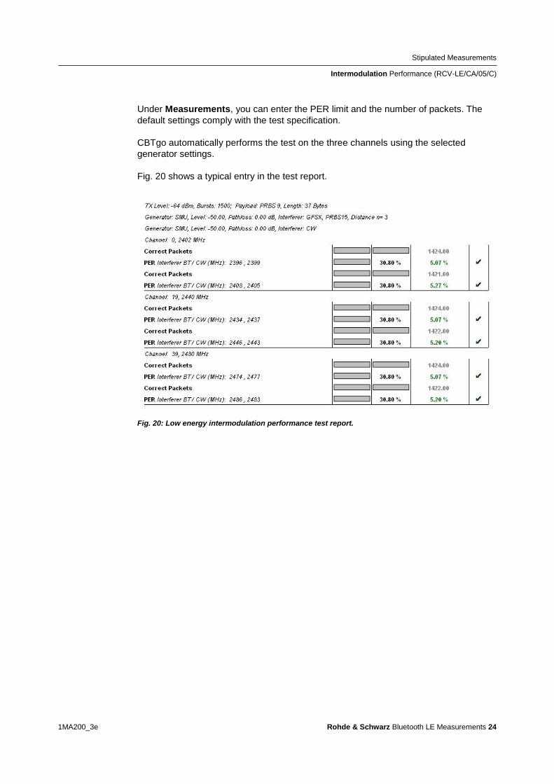
Stipulated Measurements
Intermodulation Performance (RCV-LECA05C)
1MA200_3e Rohde amp Schwarz Bluetooth LE Measurements 24
Under Measurements you can enter the PER limit and the number of packets The
default settings comply with the test specification
CBTgo automatically performs the test on the three channels using the selected
generator settings
Fig 20 shows a typical entry in the test report
Fig 20 Low energy intermodulation performance test report
Appendix
References
1MA200_3e Rohde amp Schwarz Bluetooth LE Measurements 25
4 Appendix
41 References
[1] Bluetooth Test amp Interoperability Working Group Bluetooth Low Energy RF PHY
Test Specification RF-PHYTS402 122012 Bluetooth SIG Inc
[2] Rohde amp Schwarz Manual for Windows Application CBTgo (V170)
[3] Rohde amp Schwarz Measurements on Bluetooth Products using
RampS CMU200CBT and CMUgoCBTgo Application Note 1CM50 102006
[4] Rohde amp Schwarz Bluetooth Measurements Using CBTgo Additional Tests Application Note 1MA106 022013
42 Additional Information
Please send your comments and suggestions regarding this application note to
TM-Applicationsrohde-schwarzcom
Visit the CBTgo website at
httpwww2rohde-
schwarzcomenproductstest_and_measurementmobile_radioCBT_CBT32-|-
Tools-|-67-|-1459html
or as a registered user in GLORIS the CMU Customer Web at
httpsextranetrohde-schwarzcom
Appendix
Ordering Information
1MA200_3e Rohde amp Schwarz Bluetooth LE Measurements 26
43 Ordering Information
Ordering information
Bluetooth tester
CBT Bluetooth tester with display 1153900035
CBT32 Bluetooth tester without display 1153900032
CBT-K57 Bluetooth Low Energy 1170410202
Vector signal generator
SMU200A Vector Signal Generator 1141200502
SMU-B9 Baseband Generator 128 Msample 1161076602
SMU-B10 Baseband Generator 64 Msample 1141700702
SMU-B11 Baseband Generator 16 Msample 1159841102
SMU-B13 Baseband Main Module 1141800304
SMU-B10x RF Path A
SMU-B20x RF Path B
SMW200A Vector Signal Generator 1412000002
SMW-B10 Baseband Generator with ARB
(64 Msample) and Digital Modulation
(realtime) 120 MHz RF bandwidth
1413120002
SMW-B13 Baseband Main Module one IQ path to RF 1413280702
SMW-B10x RF Path A
SMW-B20x RF Path B
SMBV100A Vector Signal Generator 1407600402
Signal generator
SMF100A Microwave Signal Generator
up to 435 GHz
1167000002
SMB100A RF and Microwave Signal Generator
up to 1275 GHz
1406600002
xx stands for the different frequency ranges (eg 1155500126 MHz to 26 GHz
Note Available options are not listed in detail
Please contact your local Rohde amp Schwarz sales office for further assistance
About Rohde amp Schwarz
Rohde amp Schwarz is an independent group
of companies specializing in electronics It is
a leading supplier of solutions in the fields of
test and measurement broadcasting
radiomonitoring and radiolocation as well as
secure communications Established more
than 75 years ago Rohde amp Schwarz has a
global presence and a dedicated service
network in over 70 countries Company
headquarters are in Munich Germany
Environmental commitment
Energy-efficient products
Continuous improvement in
environmental sustainability
ISO 14001-certified environmental
management system
Regional contact
Europe Africa Middle East
+49 89 4129 12345
customersupportrohde-schwarzcom North America
1-888-TEST-RSA (1-888-837-8772)
customersupportrsarohde-schwarzcom Latin America
+1-410-910-7988
customersupportlarohde-schwarzcom AsiaPacific
+65 65 13 04 88
customersupportasiarohde-schwarzcom
This application note and the supplied
programs may only be used subject to the
conditions of use set forth in the download
area of the Rohde amp Schwarz website
RampSreg is a registered trademark of Rohde amp Schwarz GmbH amp Co KG Trade names are trademarks of the owners
Rohde amp Schwarz GmbH amp Co KG
Muumlhldorfstraszlige 15 | D - 81671 Muumlnchen
Phone + 49 89 4129 - 0 | Fax + 49 89 4129 ndash 13777
wwwrohde-schwarzcom
Appendix
References
1MA200_3e Rohde amp Schwarz Bluetooth LE Measurements 25
4 Appendix
41 References
[1] Bluetooth Test amp Interoperability Working Group Bluetooth Low Energy RF PHY
Test Specification RF-PHYTS402 122012 Bluetooth SIG Inc
[2] Rohde amp Schwarz Manual for Windows Application CBTgo (V170)
[3] Rohde amp Schwarz Measurements on Bluetooth Products using
RampS CMU200CBT and CMUgoCBTgo Application Note 1CM50 102006
[4] Rohde amp Schwarz Bluetooth Measurements Using CBTgo Additional Tests Application Note 1MA106 022013
42 Additional Information
Please send your comments and suggestions regarding this application note to
TM-Applicationsrohde-schwarzcom
Visit the CBTgo website at
httpwww2rohde-
schwarzcomenproductstest_and_measurementmobile_radioCBT_CBT32-|-
Tools-|-67-|-1459html
or as a registered user in GLORIS the CMU Customer Web at
httpsextranetrohde-schwarzcom
Appendix
Ordering Information
1MA200_3e Rohde amp Schwarz Bluetooth LE Measurements 26
43 Ordering Information
Ordering information
Bluetooth tester
CBT Bluetooth tester with display 1153900035
CBT32 Bluetooth tester without display 1153900032
CBT-K57 Bluetooth Low Energy 1170410202
Vector signal generator
SMU200A Vector Signal Generator 1141200502
SMU-B9 Baseband Generator 128 Msample 1161076602
SMU-B10 Baseband Generator 64 Msample 1141700702
SMU-B11 Baseband Generator 16 Msample 1159841102
SMU-B13 Baseband Main Module 1141800304
SMU-B10x RF Path A
SMU-B20x RF Path B
SMW200A Vector Signal Generator 1412000002
SMW-B10 Baseband Generator with ARB
(64 Msample) and Digital Modulation
(realtime) 120 MHz RF bandwidth
1413120002
SMW-B13 Baseband Main Module one IQ path to RF 1413280702
SMW-B10x RF Path A
SMW-B20x RF Path B
SMBV100A Vector Signal Generator 1407600402
Signal generator
SMF100A Microwave Signal Generator
up to 435 GHz
1167000002
SMB100A RF and Microwave Signal Generator
up to 1275 GHz
1406600002
xx stands for the different frequency ranges (eg 1155500126 MHz to 26 GHz
Note Available options are not listed in detail
Please contact your local Rohde amp Schwarz sales office for further assistance
About Rohde amp Schwarz
Rohde amp Schwarz is an independent group
of companies specializing in electronics It is
a leading supplier of solutions in the fields of
test and measurement broadcasting
radiomonitoring and radiolocation as well as
secure communications Established more
than 75 years ago Rohde amp Schwarz has a
global presence and a dedicated service
network in over 70 countries Company
headquarters are in Munich Germany
Environmental commitment
Energy-efficient products
Continuous improvement in
environmental sustainability
ISO 14001-certified environmental
management system
Regional contact
Europe Africa Middle East
+49 89 4129 12345
customersupportrohde-schwarzcom North America
1-888-TEST-RSA (1-888-837-8772)
customersupportrsarohde-schwarzcom Latin America
+1-410-910-7988
customersupportlarohde-schwarzcom AsiaPacific
+65 65 13 04 88
customersupportasiarohde-schwarzcom
This application note and the supplied
programs may only be used subject to the
conditions of use set forth in the download
area of the Rohde amp Schwarz website
RampSreg is a registered trademark of Rohde amp Schwarz GmbH amp Co KG Trade names are trademarks of the owners
Rohde amp Schwarz GmbH amp Co KG
Muumlhldorfstraszlige 15 | D - 81671 Muumlnchen
Phone + 49 89 4129 - 0 | Fax + 49 89 4129 ndash 13777
wwwrohde-schwarzcom
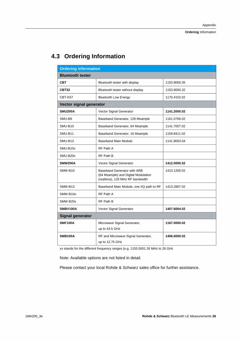


![25 &72 5(*,21$/ (6&2/$5 ,1',9,'8$/ &,8'$' 5($/ · PDF file0$5&$38(572//$12 &5 &0 &/0 w 5lfdugr &duodylood 0dq]dqduhv ... &lxgdg 5hdo pd\r viedgr pd\r vhvlyq gh wdugh](https://img.pdfslide.net/doc/110x75/5a795bdb7f8b9af91c8d3562/-25-72-521-625-198-8-5-53857212-5-0-0-w-5lfdugr-duodylood.jpg)