Embed Size (px)
Citation preview
[email protected] • ENGR-22_Lec-10_Ortho_View-3.ppt1
Bruce Mayer, PE Engineering 22 – Engineering Design Graphics
Bruce Mayer, PELicensed Electrical & Mechanical Engineer
Engineering 22
OrthroGrapOrthroGraphichic
View Dwgs-View Dwgs-33
[email protected] • ENGR-22_Lec-10_Ortho_View-3.ppt2
Bruce Mayer, PE Engineering 22 – Engineering Design Graphics
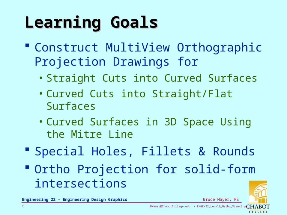
Learning GoalsLearning Goals
Construct MultiView Orthographic Projection Drawings for• Straight Cuts into Curved Surfaces
• Curved Cuts into Straight/Flat Surfaces
• Curved Surfaces in 3D Space Using the Mitre Line
Special Holes, Fillets & Rounds Ortho Projection for solid-form
intersections
[email protected] • ENGR-22_Lec-10_Ortho_View-3.ppt3
Bruce Mayer, PE Engineering 22 – Engineering Design Graphics
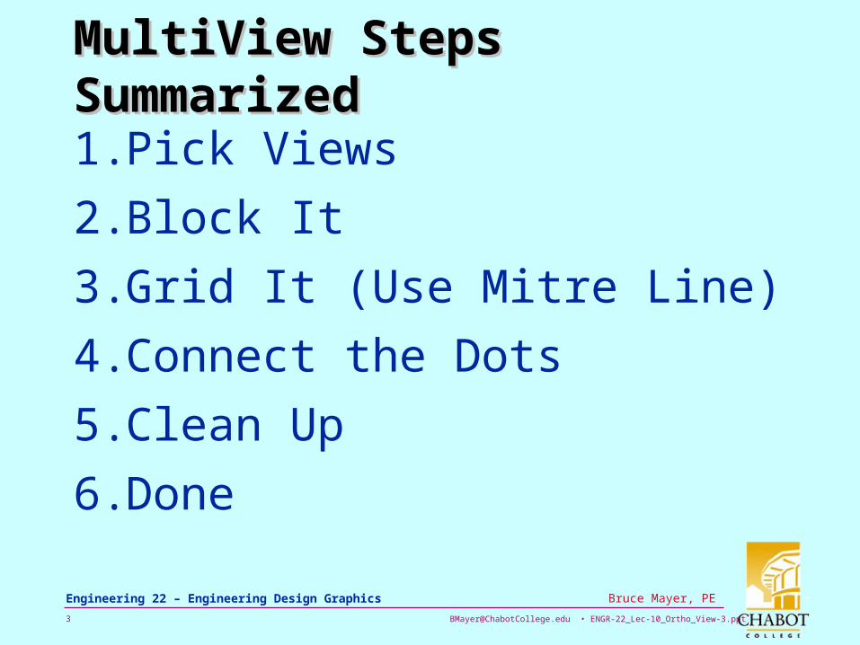
MultiView Steps SummarizedMultiView Steps Summarized
1. Pick Views
2. Block It
3. Grid It (Use Mitre Line)
4. Connect the Dots
5. Clean Up
6. Done
[email protected] • ENGR-22_Lec-10_Ortho_View-3.ppt4
Bruce Mayer, PE Engineering 22 – Engineering Design Graphics
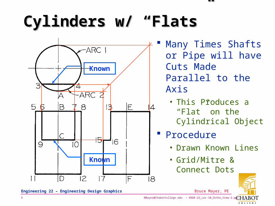
Cylinders w/ “Flats”Cylinders w/ “Flats” Many Times Shafts
or Pipe will have Cuts Made Parallel to the Axis• This Produces a
“Flat” on the Cylindrical Object
Procedure• Drawn Known Lines
• Grid/Mitre & Connect Dots
Known
Known
[email protected] • ENGR-22_Lec-10_Ortho_View-3.ppt5
Bruce Mayer, PE Engineering 22 – Engineering Design Graphics
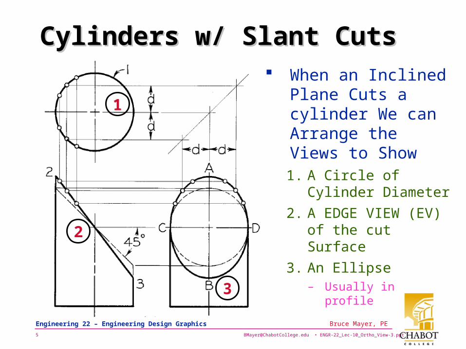
Cylinders w/ Slant CutsCylinders w/ Slant Cuts When an Inclined
Plane Cuts a cylinder We can Arrange the Views to Show1. A Circle of Cylinder
Diameter
2. A EDGE VIEW (EV) of the cut Surface
3. An Ellipse – Usually in
profile
1
2
3
[email protected] • ENGR-22_Lec-10_Ortho_View-3.ppt6
Bruce Mayer, PE Engineering 22 – Engineering Design Graphics
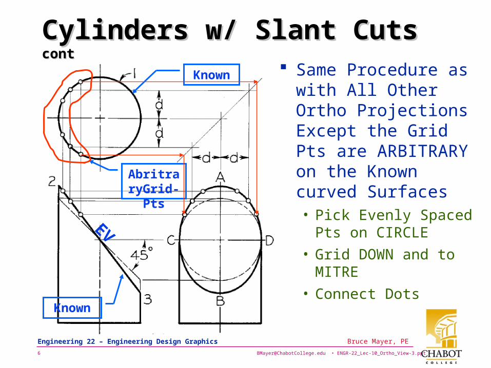
Cylinders w/ Slant Cuts Cylinders w/ Slant Cuts contcont
Same Procedure as with All Other Ortho Projections Except the Grid Pts are ARBITRARY on the Known curved Surfaces• Pick Evenly Spaced
Pts on CIRCLE
• Grid DOWN and to MITRE
• Connect Dots
Known
Known
AbritraryGrid-Pts
EV
[email protected] • ENGR-22_Lec-10_Ortho_View-3.ppt7
Bruce Mayer, PE Engineering 22 – Engineering Design Graphics
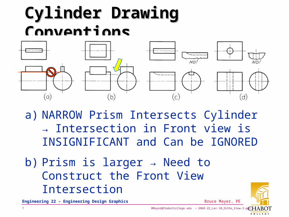
Cylinder Drawing ConventionsCylinder Drawing Conventions
a) NARROW Prism Intersects Cylinder → Intersection in Front view is INSIGNIFICANT and Can be IGNORED
b) Prism is larger → Need to Construct the Front View Intersection
[email protected] • ENGR-22_Lec-10_Ortho_View-3.ppt8
Bruce Mayer, PE Engineering 22 – Engineering Design Graphics
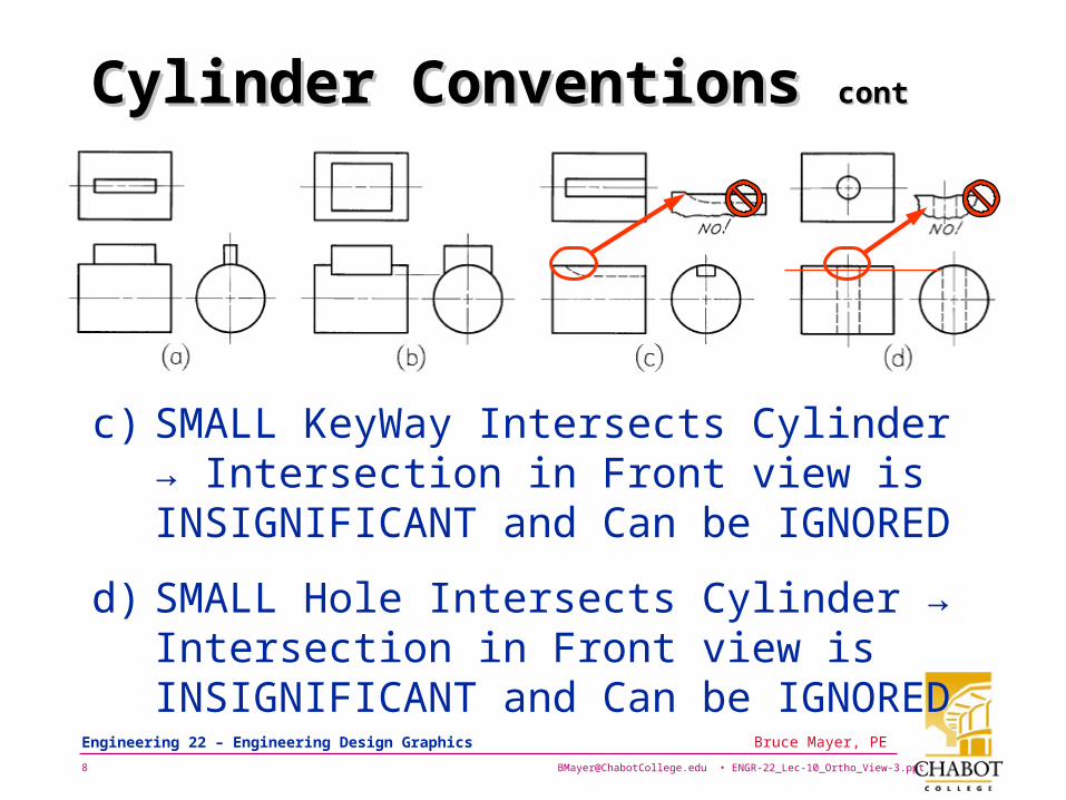
Cylinder Conventions Cylinder Conventions contcont
c) SMALL KeyWay Intersects Cylinder → Intersection in Front view is INSIGNIFICANT and Can be IGNORED
d) SMALL Hole Intersects Cylinder → Intersection in Front view is INSIGNIFICANT and Can be IGNORED
[email protected] • ENGR-22_Lec-10_Ortho_View-3.ppt9
Bruce Mayer, PE Engineering 22 – Engineering Design Graphics
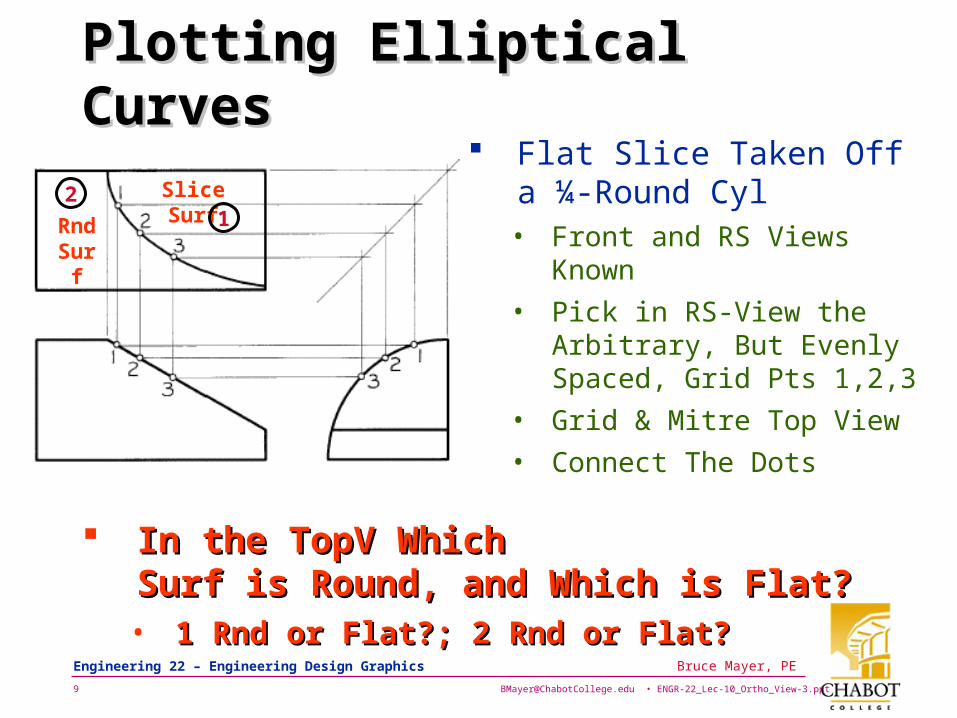
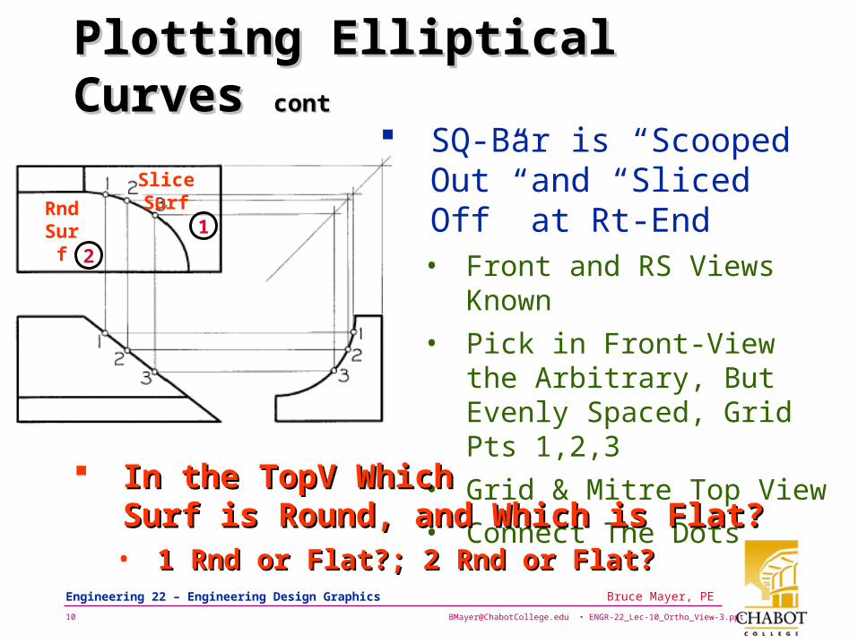
Plotting Elliptical CurvesPlotting Elliptical Curves Flat Slice Taken Off a ¼-
Round Cyl• Front and RS Views
Known
• Pick in RS-View the Arbitrary, But Evenly Spaced, Grid Pts 1,2,3
• Grid & Mitre Top View
• Connect The Dots
Slice Surf
RndSurf
12
In the TopV Which In the TopV Which Surf is Round, and Which is Flat?Surf is Round, and Which is Flat?
• 1 Rnd or Flat?; 2 Rnd or Flat?1 Rnd or Flat?; 2 Rnd or Flat?
[email protected] • ENGR-22_Lec-10_Ortho_View-3.ppt10
Bruce Mayer, PE Engineering 22 – Engineering Design Graphics
Plotting Elliptical Curves Plotting Elliptical Curves contcont
SQ-Bar is “Scooped Out” and “Sliced Off” at Rt-End• Front and RS Views Known
• Pick in Front-View the Arbitrary, But Evenly Spaced, Grid Pts 1,2,3
• Grid & Mitre Top View
• Connect The Dots
In the TopV Which In the TopV Which Surf is Round, and Which is Flat?Surf is Round, and Which is Flat?
• 1 Rnd or Flat?; 2 Rnd or Flat?1 Rnd or Flat?; 2 Rnd or Flat?
Slice Surf
RndSurf 1
2
[email protected] • ENGR-22_Lec-10_Ortho_View-3.ppt11
Bruce Mayer, PE Engineering 22 – Engineering Design Graphics
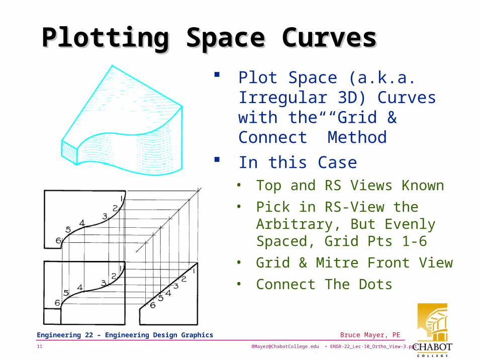
Plotting Space CurvesPlotting Space Curves Plot Space (a.k.a. Irregular
3D) Curves with the “Grid & Connect” Method
In this Case• Top and RS Views Known
• Pick in RS-View the Arbitrary, But Evenly Spaced, Grid Pts 1-6
• Grid & Mitre Front View
• Connect The Dots
[email protected] • ENGR-22_Lec-10_Ortho_View-3.ppt12
Bruce Mayer, PE Engineering 22 – Engineering Design Graphics
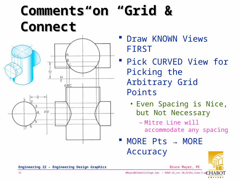
Comments on “Grid & Connect”Comments on “Grid & Connect” Draw KNOWN Views
FIRST Pick CURVED View for
Picking the Arbitrary Grid Points• Even Spacing is Nice,
but Not Necessary– Mitre Line will
accommodate any spacing
MORE Pts → MORE Accuracy
[email protected] • ENGR-22_Lec-10_Ortho_View-3.ppt13
Bruce Mayer, PE Engineering 22 – Engineering Design Graphics
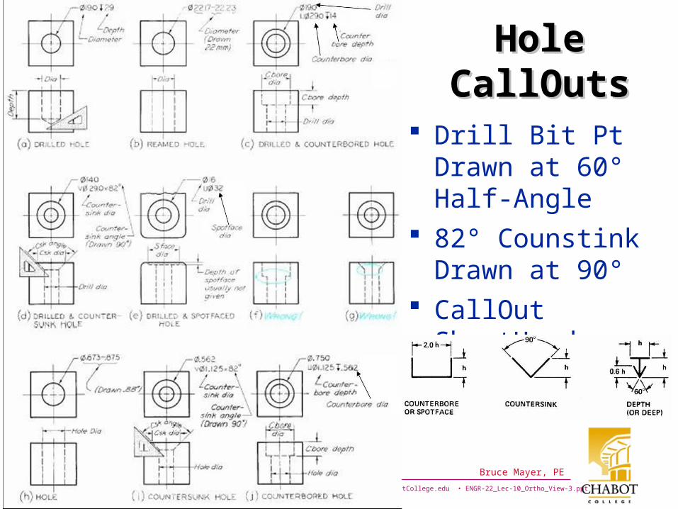
HoleHoleCallOutsCallOuts
Drill Bit Pt Drawn at 60° Half-Angle
82° Counstink Drawn at 90°
CallOut ShortHand
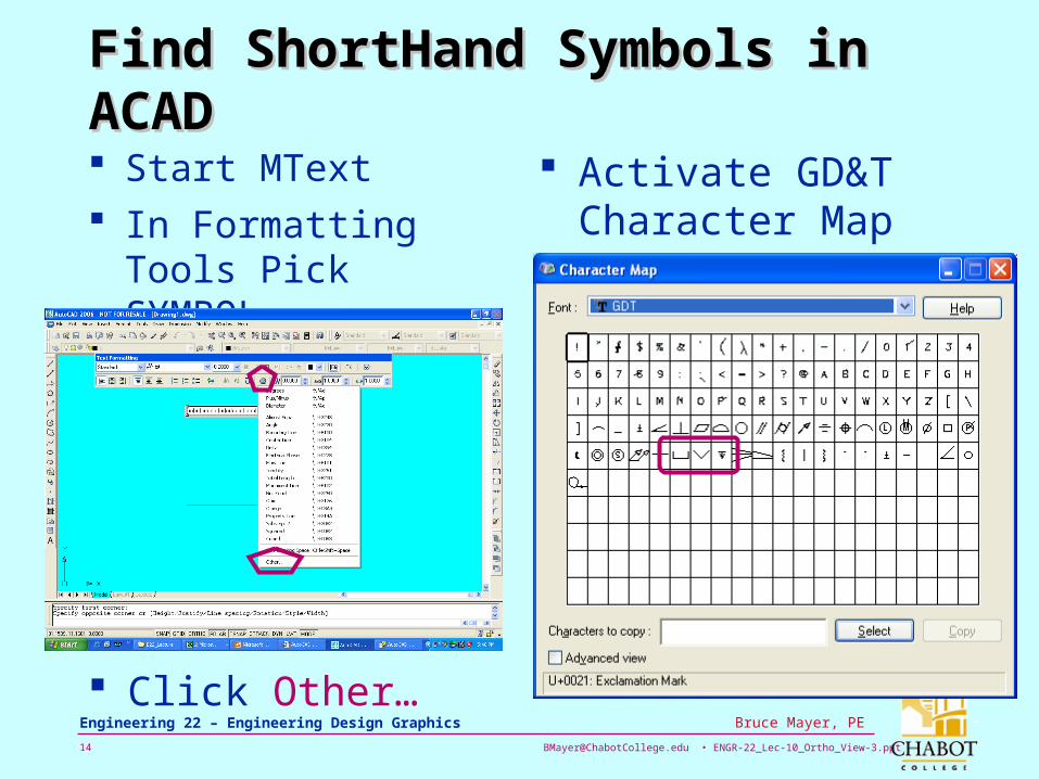
[email protected] • ENGR-22_Lec-10_Ortho_View-3.ppt14
Bruce Mayer, PE Engineering 22 – Engineering Design Graphics
Find ShortHand Symbols in ACADFind ShortHand Symbols in ACAD
Start MText In Formatting Tools
Pick SYMBOL
Click Other…
Activate GD&T Character Map
[email protected] • ENGR-22_Lec-10_Ortho_View-3.ppt15
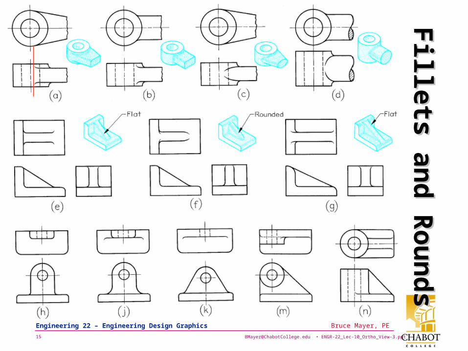
Bruce Mayer, PE Engineering 22 – Engineering Design Graphics
Fillets an
d R
ou
nd
sF
illets and
Ro
un
ds
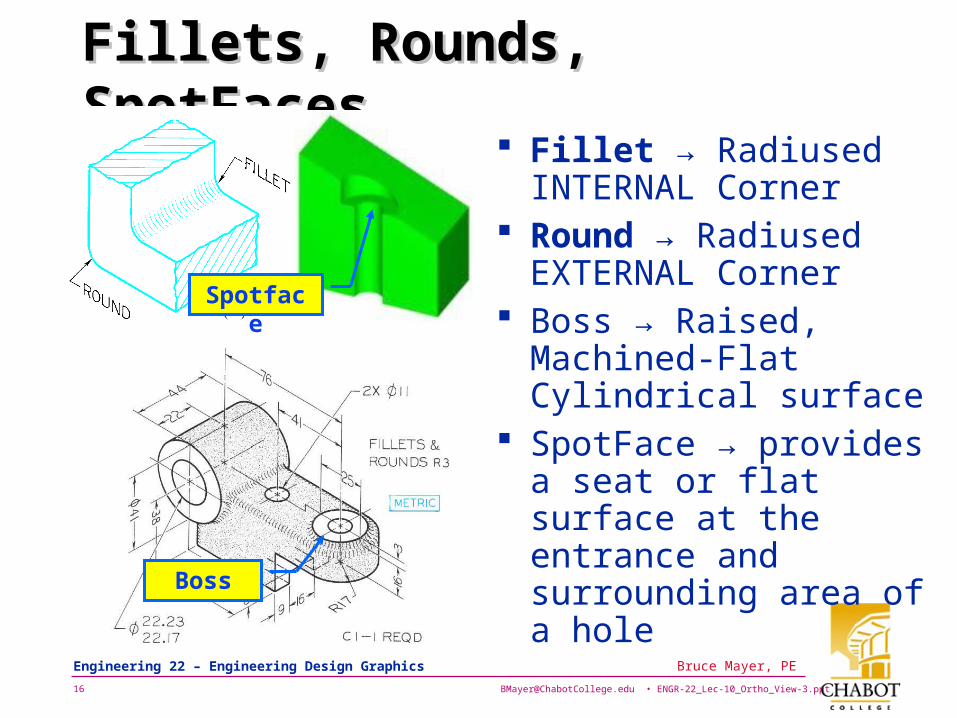
[email protected] • ENGR-22_Lec-10_Ortho_View-3.ppt16
Bruce Mayer, PE Engineering 22 – Engineering Design Graphics
Fillets, Rounds, SpotFacesFillets, Rounds, SpotFaces Fillet → Radiused
INTERNAL Corner Round → Radiused
EXTERNAL Corner Boss → Raised,
Machined-Flat Cylindrical surface
SpotFace → provides a seat or flat surface at the entrance and surrounding area of a hole
Boss
Spotface
[email protected] • ENGR-22_Lec-10_Ortho_View-3.ppt17
Bruce Mayer, PE Engineering 22 – Engineering Design Graphics
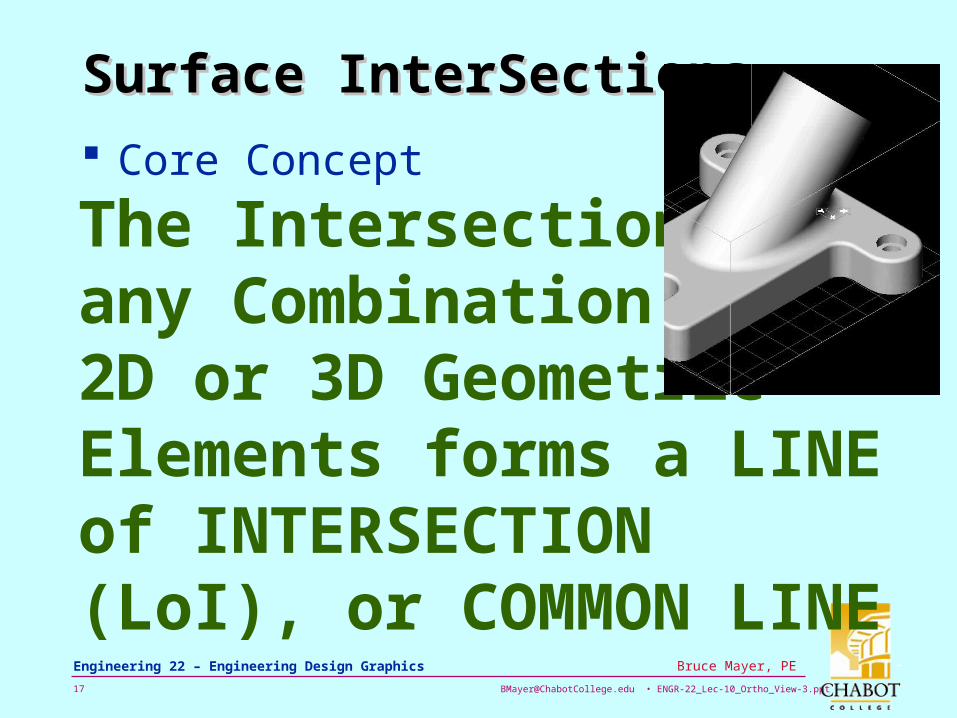
Surface InterSectionsSurface InterSections
Core Concept
The Intersection of any Combination of 2D or 3D Geometric Elements forms a LINE of INTERSECTION (LoI), or COMMON LINE
[email protected] • ENGR-22_Lec-10_Ortho_View-3.ppt18
Bruce Mayer, PE Engineering 22 – Engineering Design Graphics
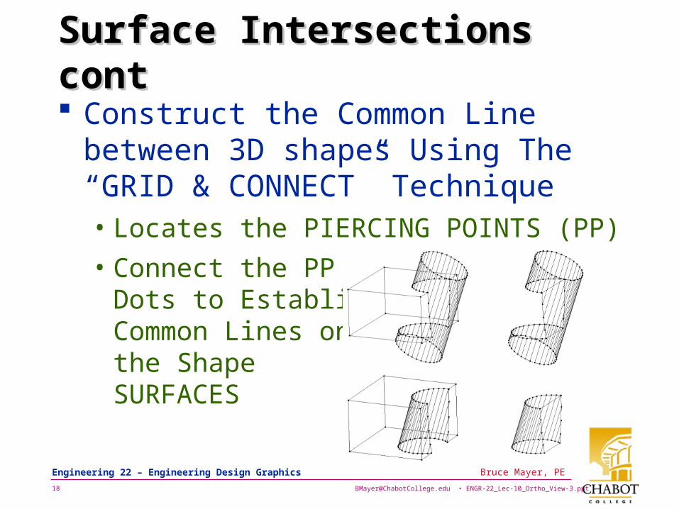
Surface Intersections contSurface Intersections cont
Construct the Common Line between 3D shapes Using The “GRID & CONNECT” Technique• Locates the PIERCING POINTS (PP)
• Connect the PP Dots to Establish Common Lines on the Shape SURFACES
[email protected] • ENGR-22_Lec-10_Ortho_View-3.ppt19
Bruce Mayer, PE Engineering 22 – Engineering Design Graphics
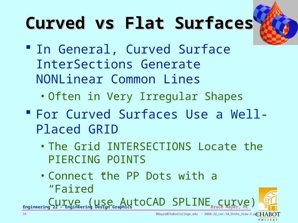
Curved vs Flat SurfacesCurved vs Flat Surfaces
In General, Curved Surface InterSections Generate NONLinear Common Lines• Often in Very Irregular Shapes
For Curved Surfaces Use a Well-Placed GRID• The Grid INTERSECTIONS Locate the
PIERCING POINTS
• Connect the PP Dots with a “Faired” Curve (use AutoCAD SPLINE curve)
[email protected] • ENGR-22_Lec-10_Ortho_View-3.ppt20
Bruce Mayer, PE Engineering 22 – Engineering Design Graphics
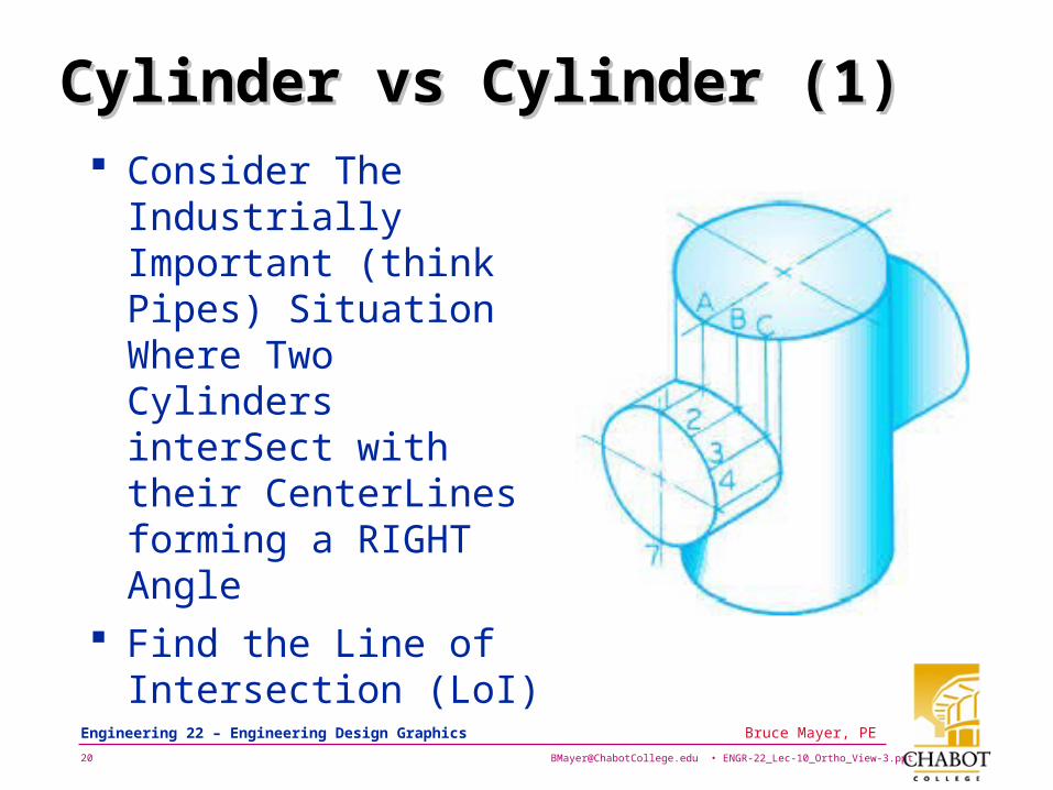
Cylinder vs Cylinder (1)Cylinder vs Cylinder (1) Consider The
Industrially Important (think Pipes) Situation Where Two Cylinders interSect with their CenterLines forming a RIGHT Angle
Find the Line of Intersection (LoI)
[email protected] • ENGR-22_Lec-10_Ortho_View-3.ppt21
Bruce Mayer, PE Engineering 22 – Engineering Design Graphics
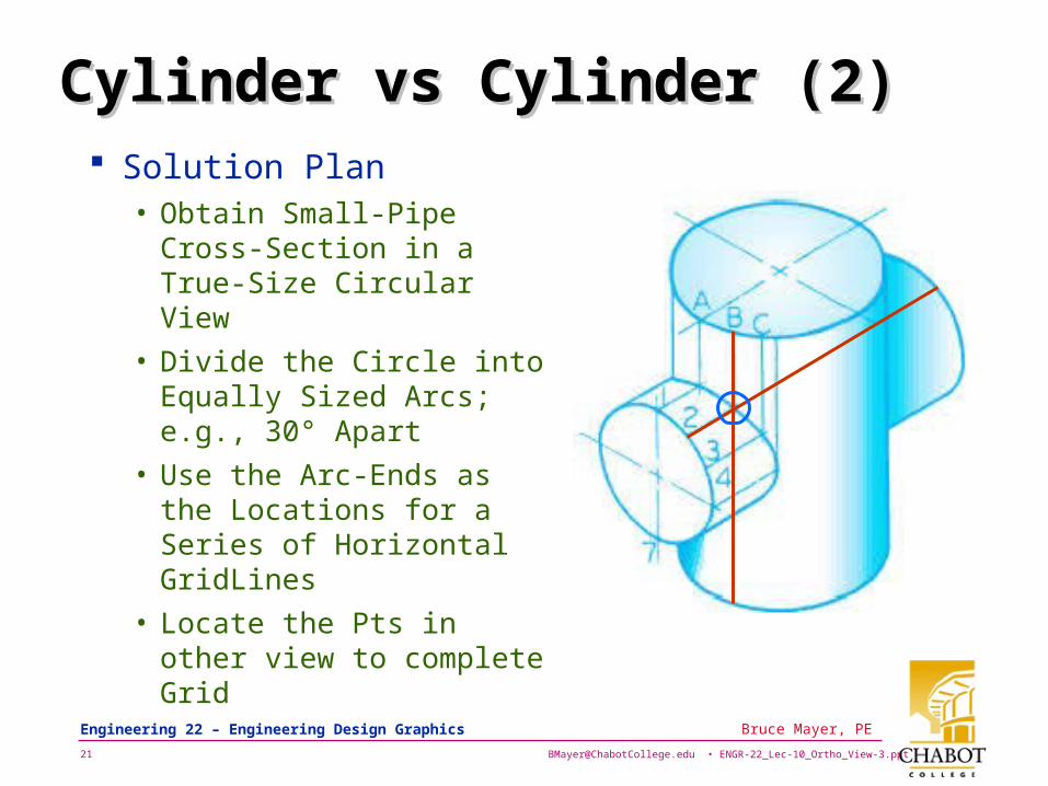
Cylinder vs Cylinder (2)Cylinder vs Cylinder (2) Solution Plan
• Obtain Small-Pipe Cross-Section in a True-Size Circular View
• Divide the Circle into Equally Sized Arcs; e.g., 30° Apart
• Use the Arc-Ends as the Locations for a Series of Horizontal GridLines
• Locate the Pts in other view to complete Grid
[email protected] • ENGR-22_Lec-10_Ortho_View-3.ppt22
Bruce Mayer, PE Engineering 22 – Engineering Design Graphics
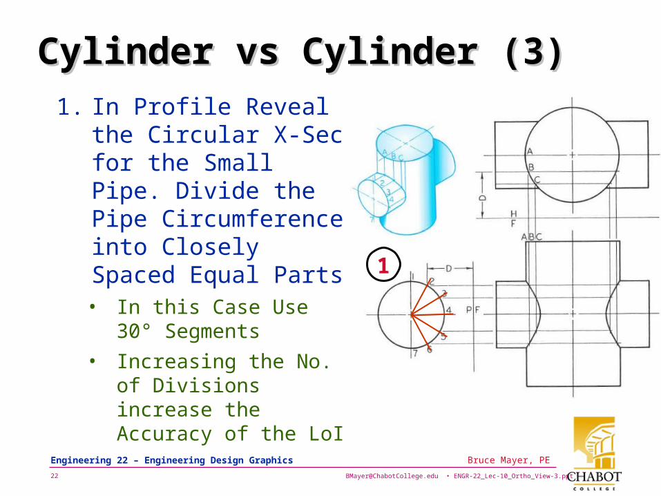
Cylinder vs Cylinder (3)Cylinder vs Cylinder (3)
1. In Profile Reveal the Circular X-Sec for the Small Pipe. Divide the Pipe Circumference into Closely Spaced Equal Parts• In this Case Use 30°
Segments
• Increasing the No. of Divisions increase the Accuracy of the LoI
1
[email protected] • ENGR-22_Lec-10_Ortho_View-3.ppt23
Bruce Mayer, PE Engineering 22 – Engineering Design Graphics
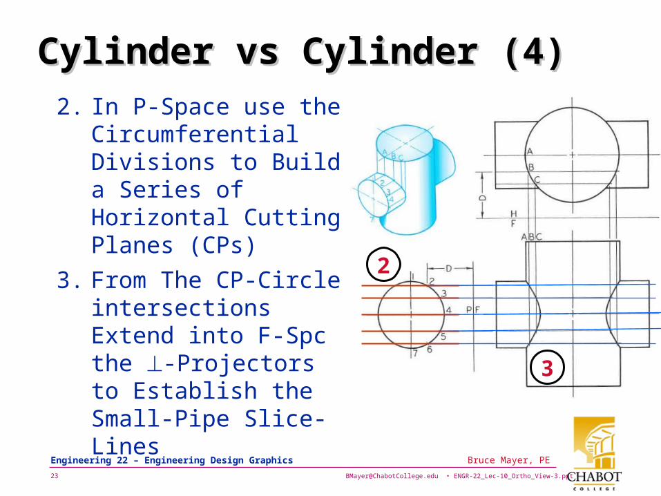
Cylinder vs Cylinder (4)Cylinder vs Cylinder (4)
2. In P-Space use the Circumferential Divisions to Build a Series of Horizontal Cutting Planes (CPs)
3. From The CP-Circle intersections Extend into F-Spc the -Projectors to Establish the Small-Pipe Slice-Lines
2
3
[email protected] • ENGR-22_Lec-10_Ortho_View-3.ppt24
Bruce Mayer, PE Engineering 22 – Engineering Design Graphics
Cylinder vs Cylinder (5)Cylinder vs Cylinder (5)
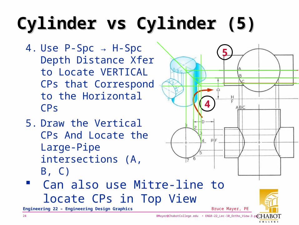
4. Use P-Spc → H-Spc Depth Distance Xfer to Locate VERTICAL CPs that Correspond to the Horizontal CPs
5. Draw the Vertical CPs And Locate the Large-Pipe intersections (A, B, C)
4
5
Can also use Mitre-line to locate CPs in Top View
[email protected] • ENGR-22_Lec-10_Ortho_View-3.ppt25
Bruce Mayer, PE Engineering 22 – Engineering Design Graphics
Cylinder vs Cylinder (5)Cylinder vs Cylinder (5)
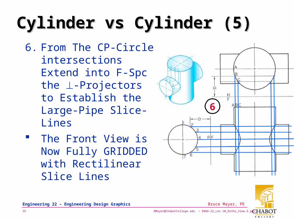
6. From The CP-Circle intersections Extend into F-Spc the -Projectors to Establish the Large-Pipe Slice-Lines
The Front View is Now Fully GRIDDED with Rectilinear Slice Lines
6
[email protected] • ENGR-22_Lec-10_Ortho_View-3.ppt26
Bruce Mayer, PE Engineering 22 – Engineering Design Graphics
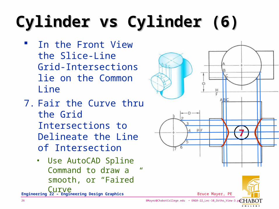
Cylinder vs Cylinder (6)Cylinder vs Cylinder (6) In the Front View the
Slice-Line Grid-Intersections lie on the Common Line
7. Fair the Curve thru the Grid Intersections to Delineate the Line of Intersection • Use AutoCAD Spline
Command to draw a smooth, or “Faired” Curve
7
[email protected] • ENGR-22_Lec-10_Ortho_View-3.ppt27
Bruce Mayer, PE Engineering 22 – Engineering Design Graphics
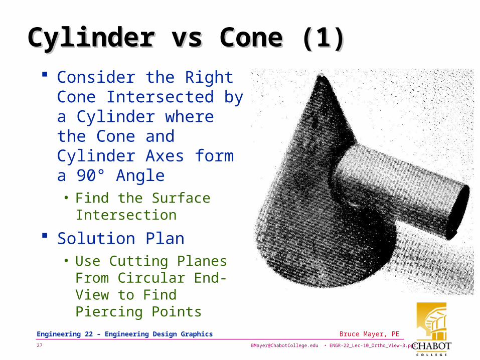
Cylinder vs Cone (1)Cylinder vs Cone (1) Consider the Right
Cone Intersected by a Cylinder where the Cone and Cylinder Axes form a 90° Angle• Find the Surface
Intersection
Solution Plan• Use Cutting Planes
From Circular End-View to Find Piercing Points
[email protected] • ENGR-22_Lec-10_Ortho_View-3.ppt28
Bruce Mayer, PE Engineering 22 – Engineering Design Graphics
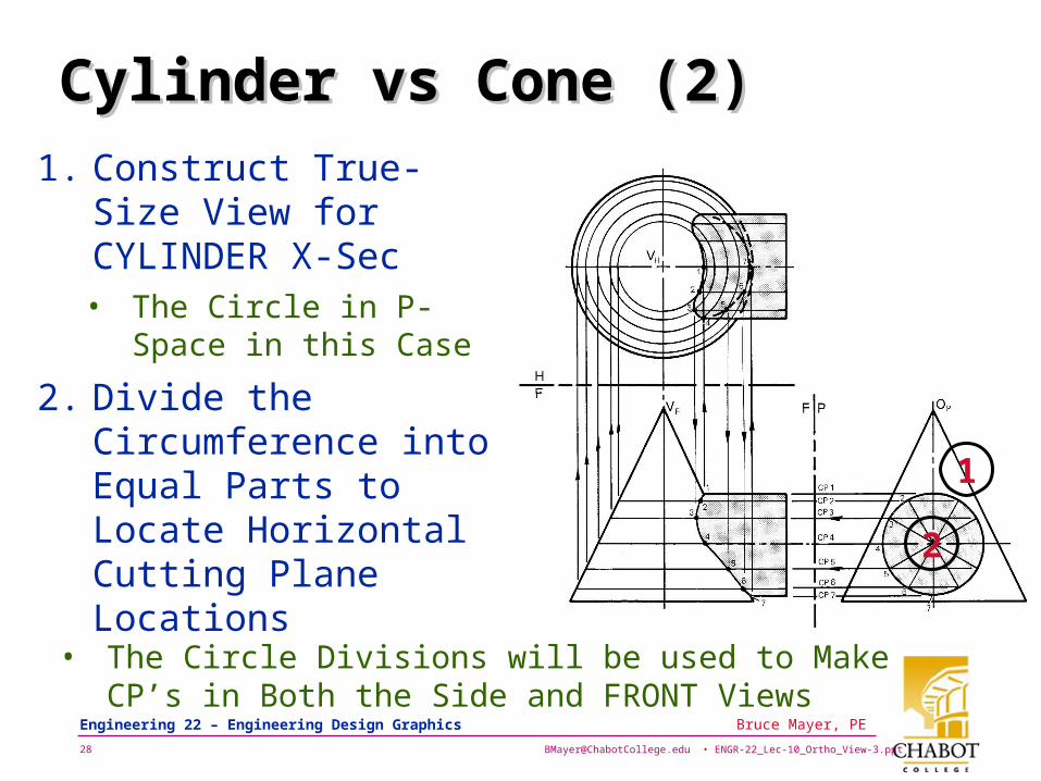
Cylinder vs Cone (2)Cylinder vs Cone (2)
1. Construct True-Size View for CYLINDER X-Sec • The Circle in P-Space
in this Case
2. Divide the Circumference into Equal Parts to Locate Horizontal Cutting Plane Locations
• The Circle Divisions will be used to Make CP’s in Both the Side and FRONT Views
1
2
[email protected] • ENGR-22_Lec-10_Ortho_View-3.ppt29
Bruce Mayer, PE Engineering 22 – Engineering Design Graphics
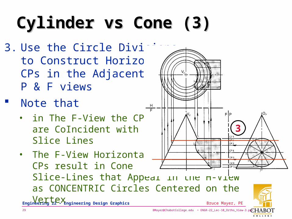
Cylinder vs Cone (3)Cylinder vs Cone (3)
3. Use the Circle Divisions to Construct Horizontal CPs in the Adjacent P & F views
Note that • in The F-View the CPs
are CoIncident with the Slice Lines
• The F-View Horizontal CPs result in Cone Slice-Lines that Appear in the H-View as CONCENTRIC Circles Centered on the Vertex
3
[email protected] • ENGR-22_Lec-10_Ortho_View-3.ppt30
Bruce Mayer, PE Engineering 22 – Engineering Design Graphics
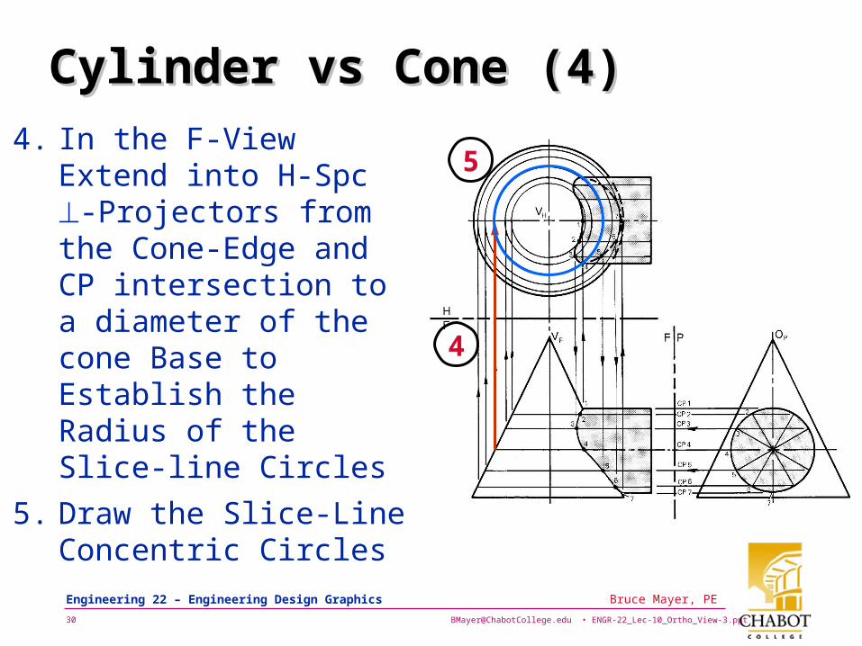
Cylinder vs Cone (4)Cylinder vs Cone (4)
4. In the F-View Extend into H-Spc -Projectors from the Cone-Edge and CP intersection to a diameter of the cone Base to Establish the Radius of the Slice-line Circles
5. Draw the Slice-Line Concentric Circles
4
5
[email protected] • ENGR-22_Lec-10_Ortho_View-3.ppt31
Bruce Mayer, PE Engineering 22 – Engineering Design Graphics
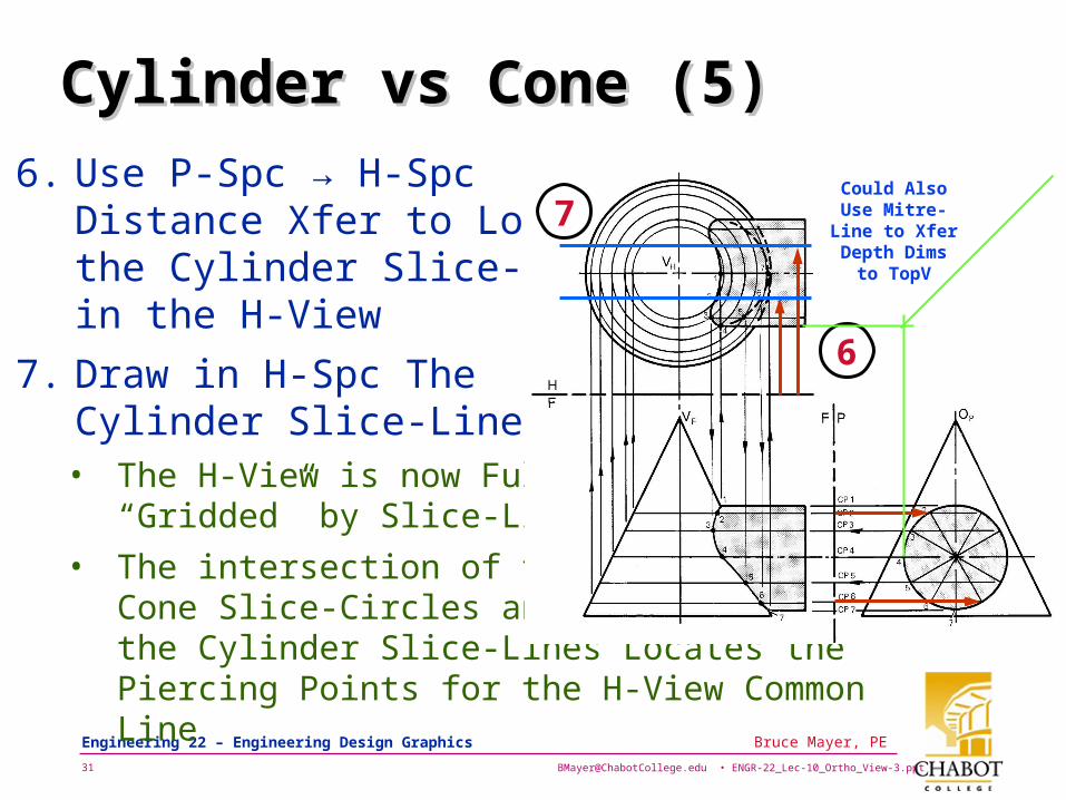
Cylinder vs Cone (5)Cylinder vs Cone (5)
6. Use P-Spc → H-Spc Distance Xfer to Locate the Cylinder Slice-Lines in the H-View
7. Draw in H-Spc The Cylinder Slice-Lines• The H-View is now Fully
“Gridded” by Slice-Lines
• The intersection of the Cone Slice-Circles and the Cylinder Slice-Lines Locates the Piercing Points for the H-View Common Line
6
7Could Also Use
Mitre-Line to Xfer Depth
Dims to TopV
[email protected] • ENGR-22_Lec-10_Ortho_View-3.ppt32
Bruce Mayer, PE Engineering 22 – Engineering Design Graphics
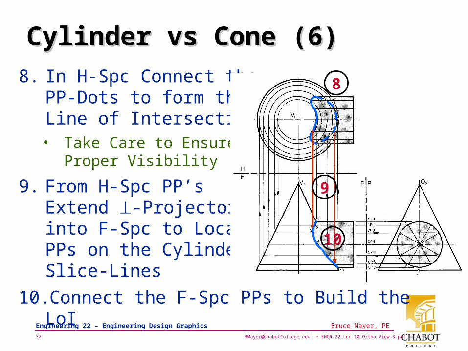
Cylinder vs Cone (6)Cylinder vs Cone (6)
8. In H-Spc Connect the PP-Dots to form the Line of Intersection• Take Care to Ensure
Proper Visibility
9. From H-Spc PP’s Extend -Projectors into F-Spc to Locate PPs on the Cylinder Slice-Lines
10.Connect the F-Spc PPs to Build the LoI
8
9
10
[email protected] • ENGR-22_Lec-10_Ortho_View-3.ppt33
Bruce Mayer, PE Engineering 22 – Engineering Design Graphics
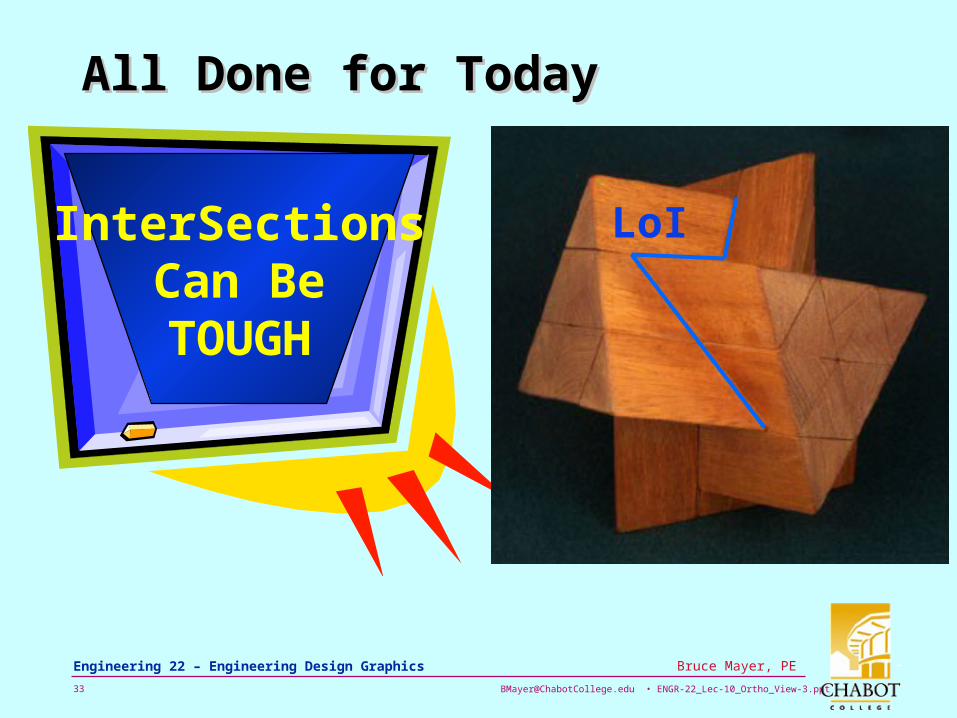
All Done for TodayAll Done for Today
InterSectionsCan BeTOUGH
LoI
[email protected] • ENGR-22_Lec-10_Ortho_View-3.ppt34
Bruce Mayer, PE Engineering 22 – Engineering Design Graphics
Bruce Mayer, PELicensed Electrical & Mechanical Engineer
Engr/Math/Physics 25
AppendiAppendixx
6972 23 xxxxf