Embed Size (px)
Citation preview
BMW N63 Performance Module Installation Instructions
Proper service and repair procedures are vital to the safe, reliable operation of all motor vehicles as well as the personal safety of those performing the repairs. Standard safety procedures and precautions (including use of safety goggles and proper tools and equipment) should be followed at all times
to eliminate the possibility of personal injury or improper service which could damage the vehicle or compromise its safety.
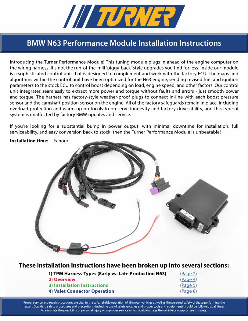
Introducing the Turner Performance Module! This tuning module plugs in ahead of the engine computer on the wiring harness. It's not the run-of-the-mill 'piggy-back' style upgrades you find for less. Inside our module is a sophisticated control unit that is designed to complement and work with the factory ECU. The maps and algorithms within the control unit have been optimized for the N63 engine, sending revised fuel and ignition parameters to the stock ECU to control boost depending on load, engine speed, and other factors. Our control unit integrates seamlessly to extract more power and torque without faults and errors - just smooth power and torque. The harness has factory-style weather-proof plugs to connect in-line with each boost pressure sensor and the camshaft position sensor on the engine. All of the factory safeguards remain in place, including overload protection and warm-up protocols to preserve longevity and factory drive-ability, and this type of system is unaffected by factory BMW updates and service.
If you're looking for a substantial bump in power output, with minimal downtime for installation, full serviceability, and easy conversion back to stock, then the Turner Performance Module is unbeatable!
Installation time: 1/2 hour
These installation instructions have been broken up into several sections:1) TPM Harness Types (Early vs. Late Production N63) (Page 2)2) Overview (Page 4)3) Installation Instructions (Page 5)4) Valet Connector Operation (Page 8)
BMW N63 PERFORMANCE MODULE INSTALLATION INSTRUCTIONS
© 2018 TURNER MOTORSPORT 16 SOUTH HUNT RD. AMESBURY, MA 01913 1.800.280.6966 WWW.TURNERMOTORSPORT.COM PAGE 2 OF 8
T#387341
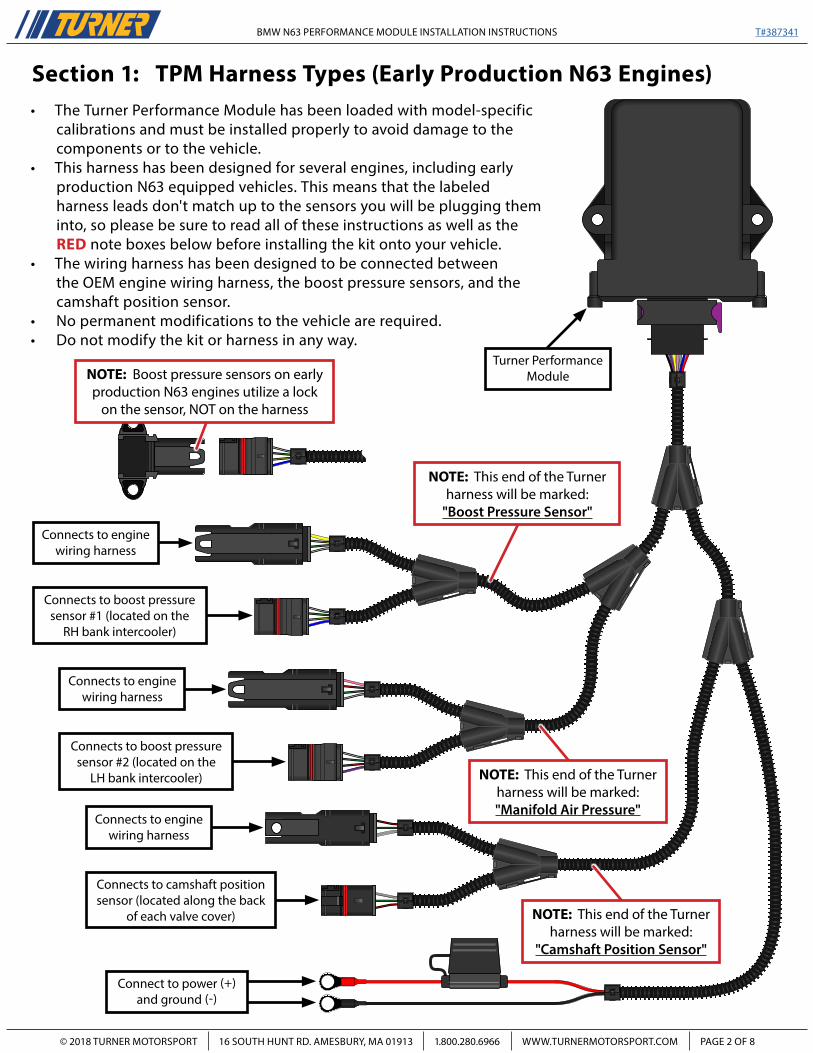
Section 1: TPM Harness Types (Early Production N63 Engines)
Connects to engine wiring harness
Connects to engine wiring harness
Connect to power (+) and ground (-)
Connects to engine wiring harness
Connects to boost pressure sensor #2 (located on the
LH bank intercooler)
Connects to camshaft position sensor (located along the back
of each valve cover)
Connects to boost pressure sensor #1 (located on the
RH bank intercooler)
NOTE: This end of the Turner harness will be marked:
"Boost Pressure Sensor"
NOTE: This end of the Turner harness will be marked:"Manifold Air Pressure"
NOTE: Boost pressure sensors on early production N63 engines utilize a lock
on the sensor, NOT on the harness
• The Turner Performance Module has been loaded with model-specific calibrations and must be installed properly to avoid damage to the components or to the vehicle.
• This harness has been designed for several engines, including early production N63 equipped vehicles. This means that the labeled harness leads don't match up to the sensors you will be plugging them into, so please be sure to read all of these instructions as well as the RED note boxes below before installing the kit onto your vehicle.
• The wiring harness has been designed to be connected between the OEM engine wiring harness, the boost pressure sensors, and the camshaft position sensor.
• No permanent modifications to the vehicle are required.• Do not modify the kit or harness in any way.
Turner Performance Module
NOTE: This end of the Turner harness will be marked:
"Camshaft Position Sensor"
BMW N63 PERFORMANCE MODULE INSTALLATION INSTRUCTIONS
© 2018 TURNER MOTORSPORT 16 SOUTH HUNT RD. AMESBURY, MA 01913 1.800.280.6966 WWW.TURNERMOTORSPORT.COM PAGE 3 OF 8
T#387341
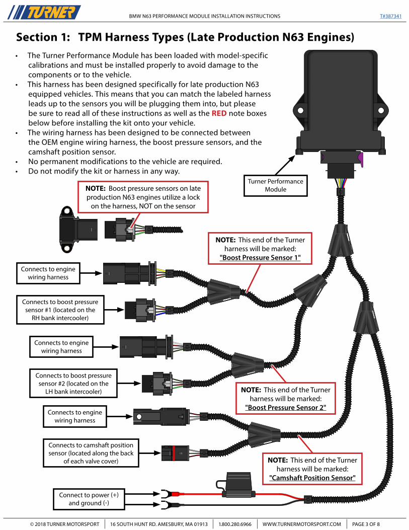
Connects to engine wiring harness
Connects to engine wiring harness
Connect to power (+) and ground (-)
Connects to engine wiring harness
Connects to boost pressure sensor #2 (located on the
LH bank intercooler)
Connects to camshaft position sensor (located along the back
of each valve cover)
Connects to boost pressure sensor #1 (located on the
RH bank intercooler)
NOTE: This end of the Turner harness will be marked:
"Boost Pressure Sensor 1"
NOTE: This end of the Turner harness will be marked:
"Boost Pressure Sensor 2"
Turner Performance Module
NOTE: This end of the Turner harness will be marked:
"Camshaft Position Sensor"
Section 1: TPM Harness Types (Late Production N63 Engines)• The Turner Performance Module has been loaded with model-specific
calibrations and must be installed properly to avoid damage to the components or to the vehicle.
• This harness has been designed specifically for late production N63 equipped vehicles. This means that you can match the labeled harness leads up to the sensors you will be plugging them into, but please be sure to read all of these instructions as well as the RED note boxes below before installing the kit onto your vehicle.
• The wiring harness has been designed to be connected between the OEM engine wiring harness, the boost pressure sensors, and the camshaft position sensor.
• No permanent modifications to the vehicle are required.• Do not modify the kit or harness in any way.
NOTE: Boost pressure sensors on late production N63 engines utilize a lock
on the harness, NOT on the sensor
BMW N63 PERFORMANCE MODULE INSTALLATION INSTRUCTIONS
© 2018 TURNER MOTORSPORT 16 SOUTH HUNT RD. AMESBURY, MA 01913 1.800.280.6966 WWW.TURNERMOTORSPORT.COM PAGE 4 OF 8
T#387341
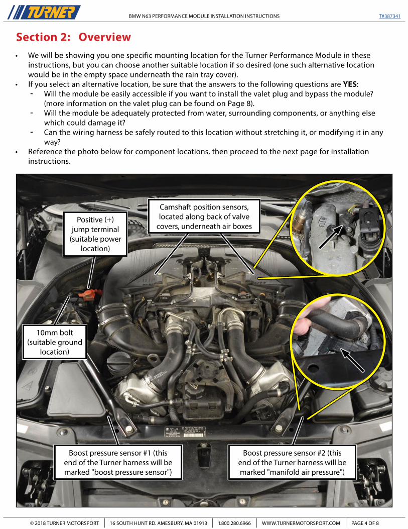
Section 2: Overview• We will be showing you one specific mounting location for the Turner Performance Module in these
instructions, but you can choose another suitable location if so desired (one such alternative location would be in the empty space underneath the rain tray cover).
• If you select an alternative location, be sure that the answers to the following questions are YES:- Will the module be easily accessible if you want to install the valet plug and bypass the module?
(more information on the valet plug can be found on Page 8).- Will the module be adequately protected from water, surrounding components, or anything else
which could damage it?- Can the wiring harness be safely routed to this location without stretching it, or modifying it in any
way?• Reference the photo below for component locations, then proceed to the next page for installation
instructions.
10mm bolt (suitable ground
location)
Positive (+) jump terminal
(suitable power location)
Boost pressure sensor #2 (this end of the Turner harness will be marked "manifold air pressure")
Camshaft position sensors, located along back of valve
covers, underneath air boxes
Boost pressure sensor #1 (this end of the Turner harness will be marked "boost pressure sensor")
BMW N63 PERFORMANCE MODULE INSTALLATION INSTRUCTIONS
© 2018 TURNER MOTORSPORT 16 SOUTH HUNT RD. AMESBURY, MA 01913 1.800.280.6966 WWW.TURNERMOTORSPORT.COM PAGE 5 OF 8
T#387341
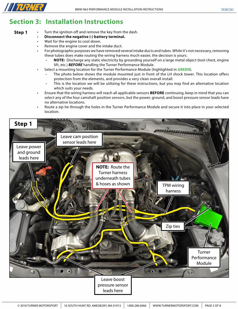
Section 3: Installation InstructionsStep 1 • Turn the ignition off and remove the key from the dash.
• Disconnect the negative (-) battery terminal.• Wait for the engine to cool down.• Remove the engine cover and the intake duct.• For photographic purposes we have removed several intake ducts and tubes. While it's not necessary, removing
these tubes does make routing the wiring harness much easier, the decision is yours.- NOTE: Discharge any static electricity by grounding yourself on a large metal object (tool chest, engine
lift, etc.) BEFORE handling the Turner Performance Module.• Select a mounting location for the Turner Performance Module (highlighted in GREEN).
- The photo below shows the module mounted just in front of the LH shock tower. This location offers protection from the elements, and provides a very clean overall install.
- This is the location we will be utilizing for these instructions, but you may find an alternative location which suits your needs.
• Ensure that the wiring harness will reach all applicable sensors BEFORE continuing, keep in mind that you can select any of the four camshaft position sensors, but the power, ground, and boost pressure sensor leads have no alternative locations.
• Route a zip tie through the holes in the Turner Performance Module and secure it into place in your selected location.
Step 1
TurnerPerformance
Module
NOTE: Route the Turner harness
underneath tubes & hoses as shown
Leave boost pressure sensor
leads here
Leave cam position sensor leads here
Leave power and ground leads here
TPM wiring harness
Zip ties
BMW N63 PERFORMANCE MODULE INSTALLATION INSTRUCTIONS
© 2018 TURNER MOTORSPORT 16 SOUTH HUNT RD. AMESBURY, MA 01913 1.800.280.6966 WWW.TURNERMOTORSPORT.COM PAGE 6 OF 8
T#387341
Step 2 Step 3
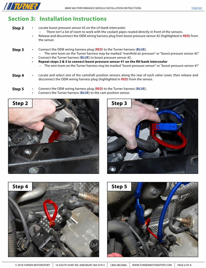
Section 3: Installation InstructionsStep 2
Step 3
Step 4 Step 5
Step 4
Step 5
• Locate and select one of the camshaft position sensors along the rear of each valve cover, then release and disconnect the OEM wiring harness plug (highlighted in RED) from the sensor.
• Connect the OEM wiring harness plug (RED) to the Turner harness (BLUE).• Connect the Turner harness (BLUE) to the cam position sensor.
• Locate boost pressure sensor #2 on the LH bank intercooler.- There isn't a lot of room to work with the coolant pipes routed directly in front of the sensors.
• Release and disconnect the OEM wiring harness plug from boost pressure sensor #2 (highlighted in RED) from the sensor.
• Connect the OEM wiring harness plug (RED) to the Turner harness (BLUE).- The wire loom on the Turner harness may be marked "manifold air pressure" or "boost pressure sensor #2"
• Connect the Turner harness (BLUE) to boost pressure sensor #2.• Repeat steps 2 & 3 to connect boost pressure sensor #1 on the RH bank intercooler
- The wire loom on the Turner harness may be marked "boost pressure sensor" or "boost pressure sensor #1"
BMW N63 PERFORMANCE MODULE INSTALLATION INSTRUCTIONS
© 2018 TURNER MOTORSPORT 16 SOUTH HUNT RD. AMESBURY, MA 01913 1.800.280.6966 WWW.TURNERMOTORSPORT.COM PAGE 7 OF 8
T#387341
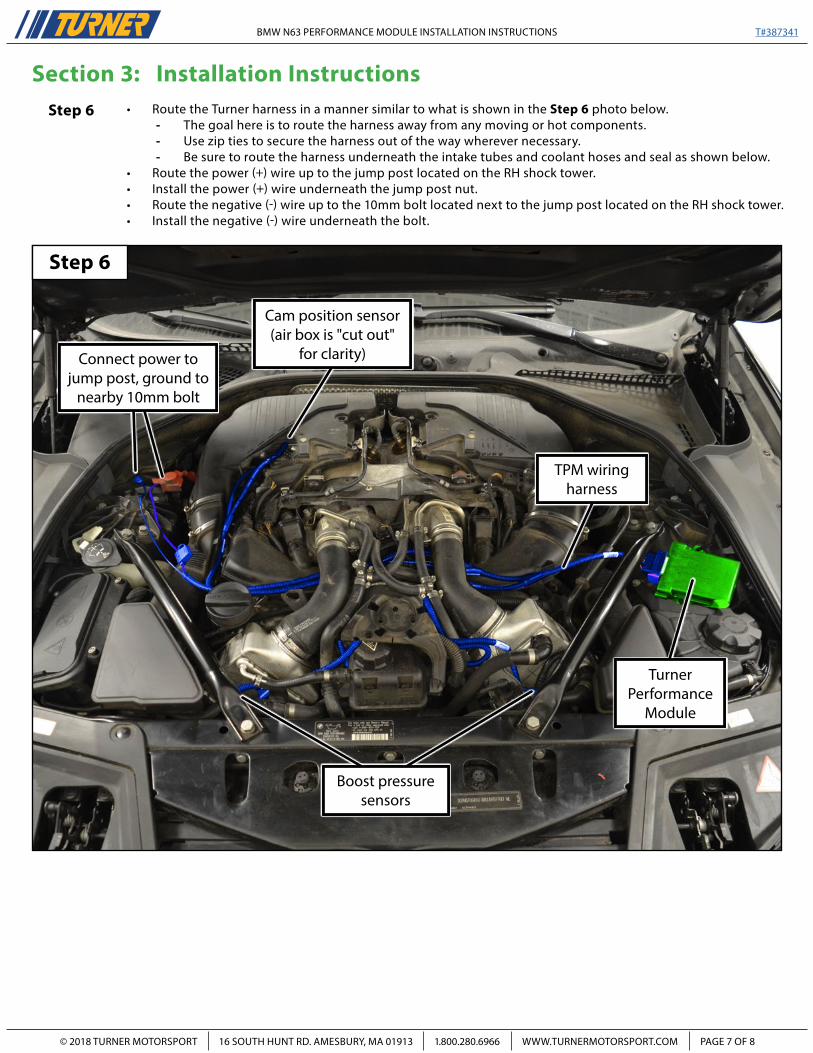
Section 3: Installation InstructionsStep 6 • Route the Turner harness in a manner similar to what is shown in the Step 6 photo below.
- The goal here is to route the harness away from any moving or hot components.- Use zip ties to secure the harness out of the way wherever necessary.- Be sure to route the harness underneath the intake tubes and coolant hoses and seal as shown below.
• Route the power (+) wire up to the jump post located on the RH shock tower.• Install the power (+) wire underneath the jump post nut.• Route the negative (-) wire up to the 10mm bolt located next to the jump post located on the RH shock tower.• Install the negative (-) wire underneath the bolt.
Step 6
TurnerPerformance
Module
Boost pressure sensors
Cam position sensor (air box is "cut out"
for clarity)
TPM wiring harness
Connect power to jump post, ground to
nearby 10mm bolt
BMW N63 PERFORMANCE MODULE INSTALLATION INSTRUCTIONS
© 2018 TURNER MOTORSPORT 16 SOUTH HUNT RD. AMESBURY, MA 01913 1.800.280.6966 WWW.TURNERMOTORSPORT.COM PAGE 8 OF 8
T#387341
Loremaga
13100402
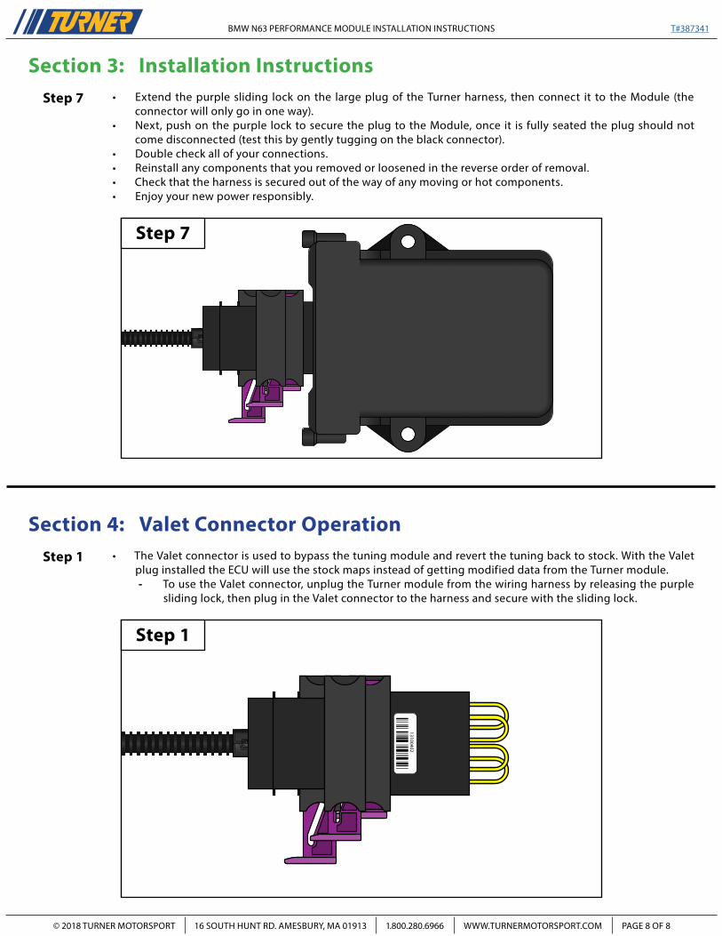
Section 4: Valet Connector Operation
Step 7
Step 1
• Extend the purple sliding lock on the large plug of the Turner harness, then connect it to the Module (the connector will only go in one way).
• Next, push on the purple lock to secure the plug to the Module, once it is fully seated the plug should not come disconnected (test this by gently tugging on the black connector).
• Double check all of your connections.• Reinstall any components that you removed or loosened in the reverse order of removal.• Check that the harness is secured out of the way of any moving or hot components.• Enjoy your new power responsibly.
• The Valet connector is used to bypass the tuning module and revert the tuning back to stock. With the Valet plug installed the ECU will use the stock maps instead of getting modified data from the Turner module.- To use the Valet connector, unplug the Turner module from the wiring harness by releasing the purple
sliding lock, then plug in the Valet connector to the harness and secure with the sliding lock.
Step 1
Step 7
Section 3: Installation Instructions


![FCAR F3 Diagnosis list Automaker: BMW Software … f5-g_coverage/MINI BMW...... [Footwell module 2] √ √ √ √ √ - ... [Dynamic Stability control] E90_Unit_Coding(KWP) ... Central](https://img.pdfslide.net/doc/110x75/5aad73877f8b9a693f8e5f5e/fcar-f3-diagnosis-list-automaker-bmw-software-f5-gcoveragemini-bmw.jpg)