Embed Size (px)
Citation preview
Rep. ITU-R BO.2019 1
REPORT ITU-R BO.2019
INTERFERENCE CALCULATION METHODS
(1999)
Rep. ITU-R BO.2019
1 Introduction
A Special Rapporteur’s Group was established during the ITU-R Joint Working Party (JWP) 10-11S meeting of October 1993 in order to develop methods for interference calculation in response to a question from the Radiocom-munication Bureau (BR) (see Question ITU-R 223/11). The mandate of this group was extended during the JWP 10-11S meeting of November-December 1994 in order to cover also the compatibility between broadcasting-satellite service (BSS) transmissions in Appendices S30/30 and S30A/30A of the Radio Regulation (RR) guardbands with space operation service, and the technical feasibility to extend the application of RR No. S5.492* to Regions 1 and 3 Plans for the introduction of fixed-satellite service (FSS) carriers in these Plans. The different tasks entrusted to this group are presented in Annex B to Annex 4 to Doc. 10-11S/1 (Chairman’s Report, 31 October 1995).
The purpose of this Report is to present the new results of the work made by some participants to the group since December 1994, to summarize the result of these studies and to elaborate a draft new Recommendation proposing updated criteria and associated methods to be taken into account for the future revision of RR Appendices S30/30 and S30A/30A Plans of Regions 1 and 3.
Section 2 presents the current protection ratios (PRs) of RR Appendix 30 and describes the methodologies applied by the BR to assess the interference situation between analogue or digital assignments. This section includes the description of the provisional model provided to the BR in October 1993 by JWP 10-11S in order to assess interference from digital carriers into standard analogue carriers. In addition, new considerations are presented on the assumptions made to implement this model in the ITU MSPACE software. Reference is also made to a new general interference calculation method which allows the calculations to be performed for different frequency offsets and different wanted and inter-fering signal types, based on a set of PR masks (see Doc. 10-11S/89 – Protection masks and associated interference calculation methods for the BSS Plans, 7 October 1996 and Doc. 10-11S/TEMP/61; Preliminary Draft Recommen-dation ITU-R BO.[AAA/11] – Protection masks and associated interference calculation methods to be used in Appendices 30 and 30A BSS Plans of the Radio Regulations, October 1996).
Section 3 presents the main results of the different contributions received up to now on interference calculation between BSS carriers (see Doc. 10-11S/1, Chairman’s Report, Annexes 1 and 2 to Attachment 2, 31 October 1995; Doc. 10-11S/27 – Measured protection ratios for PAL FM television interference into digital television transmissions in the BSS band, 21 March 1996; France’s contribution to the Rapporteur’s Group, 21 March 1996; Doc. 10-11S/84 – Technical parameters for the modernization of the WARC-BS Plan, 4 October 1996; Doc. 10-11S/57 (Add. 1) – Further modifications to Appendices 30/30A procedures not related to the simplification of the procedures, 11 October 1996; Doc. 10-11S/91 (Add. 1) – Thoughts and comments on a proposal for a protection ratio calculation method for narrow band digital satellite signals, 15 October 1996; Report ITU-R BO.634 – Broadcasting-satellite service (sound and television). Measured interference protection ratios for planning television broadcasting systems, and Doc. 10-11S/82 – Liaison statement from WP 4A, 24 November 1994).
_______________
* Note by the Secretariat: No. S5.492 of the Radio Regulations (edition of 1998), now in force, has replaced No. 846 of the Radio Regulation (edition of 1994).

2 Rep. ITU-R BO.2019
Section 4 presents preliminary results on sharing between BSS transmissions and space services based on the information available in the relevant Reports and contributions (see Report ITU-R BO.807 – Unwanted emissions from broadcasting-satellite space stations; Report ITU-R BO.1076 – Considerations affecting the accommodation of spacecraft service functions (TTC) within the broadcasting-satellite and feeder-link service bands; Doc. 10-11S/153 –Study of interference caused to a television channel by satellite telecommand carriers, 17 June 1981; Doc. 10-11S/178 – European broadcast satellite services – considerations affecting the accomodation of spacecraft service function (TTC) within the broadcast-satellite frequency assignments, 23 September 1981; Doc. 10-11S/8 – Compatibility between space operating links and feeder-links to broadcasting satellites (protection ratio), 13 May 1983; Doc. 10-11S/9 – Study of interference caused by television signals to space operation signals on broadcasting satellites in Regions 1 and 3, 13 May 1983; Doc. 10-11S/26 – Feasibility of collocating broadcasting satellites, 19 May 1983, and Doc. 10-11S/35 – Considerations affecting the accommodation of spacecraft service functions (TCC) within the broadcast satellite service bands, 3 June 1983 and Corr. 1, 6 September 1983).
Section 5 presents preliminary information on the interference from FSS transmission into the BSS Plan assignments (see Recommendation ITU-R S.483 – Maximum permissible level of interference in a television channel of a geostationary-satellite network in the fixed-satellite service employing frequency modulation, caused by other networks of this service; Doc. 4A/TEMP/36 – Preliminary draft modification of Recommendation 483-2, 21 November 1994; Doc. 4A/TEMP/38 – Draft revision of Report 867 – Maximum permissible level of FM/TV interference in single-channel-per-carrier and intermediate rate digital transmissions in networks of the fixed-satellite service, 21 November 1994; Doc. 4A/TEMP/39 – Draft new Report – Interference from FDM/FM, QPSK and TV/FM signals into analogue TV/FM signals, 21 November 1994, and Doc. 10-11S/45 – Use of BSS Plan Assignments for FSS transmissions, 29 August 1996).
Section 6 presents the views of this Special Rapporteur’s Group on the possible evolution of the existing PRs to be used in the future for the BSS Plans.
2 RR Appendices 30 and 30A protection ratios and methodology
2.1 Protection ratios and methodology applied prior to the World Radiocommunication Conference (Geneva 1997) (WRC-97) (see Note 1)
NOTE 1 – See § 2.2 for protection ratios and methodology applied following WRC-97 decisions.
2.1.1 Applicable PRs prior to WRC-97
The current PRs defined in RR Appendix 30 come from § 3.1.1 of Report ITU-R BO.634 which presents the protection masks used for the planning of BSS Plans for Regions 1 and 3 (Fig. 1a, curve B of Report ITU-R BO.634) and Region 2 (Fig. 1b of Report ITU-R BO.634).
For Regions 1 and 3, PRs are:
– 31 dB for the co-channel;
– 15 dB for the lower and upper adjacent channels with 19.18 MHz centre frequency separation.
These PRs correspond to standard PAL/SECAM FM TV signals with frequency deviation of 13.5 MHz/V and energy dispersal of 600 kHz peak-to-peak.
For Region 2, PRs are:
– 28 dB for the co-channel;
– 13.6 dB for the first lower and the first upper adjacent channels with 14.58 MHz centre frequency separation;
– –9.9 dB for the second lower and the second upper adjacent channels with 29.16 MHz centre frequency separation.
These PRs correspond to standard NTSC FM TV signals with frequency deviation of 13.5 MHz/V and energy dispersal of 600 kHz peak-to-peak.

Rep. ITU-R BO.2019 3
2.1.2 Calculation of equivalent protection margin/overall equivalent protection margin (EPM/OEPM) for cases involving only analogue signals
For the assessment of the interference situation in Regions 1 and 3, the BR calculates EPM as follows:
EPM = –10 log (10–Mcc/10 + 10–Mlac/10 + 10–Muac/10)
where:
Mcc : co-channel margin = (C/I)cc – PRcc
Mlac : lower adjacent channel margin = (C/I)lac – PRlac
Muac : upper adjacent channel margin = (C/I)uac – PRuac
where:
PRcc : co-channel protection ratio = 31 dB
PRlac and PRuac : respectively lower and upper adjacent channel protection ratios = 15 dB
(C/I)cc, (C/I)lac and (C/I)uac : respectively co-channel, lower and upper adjacent channel aggregates (C/I).
The same calculation is made for Regions 1 and 3 feeder-links based on a co-channel PR of 40 dB and an adjacent channel PR of 21 dB.
For the assessment of the overall link interference the OEPM calculation for Regions 1 and 3, the method from RR Appendix 30A, Annex 3, § 1.12, could be used in the future revisions of Plans by WRC-97.
For the assessment of the interference situation in Region 2, the BR calculates OEPM as follows:
OEPM = –10 log (10–Mcc/10 + 10–Mflac/10 + 10–Mfuac/10 + 10–Mslac/10 + 10–Msuac/10)
where:
Mcc : co-channel margin = (C/I)cc – PRcc
Mflac : first lower adjacent channel margin = (C/I)flac – PRflac
Mfuac : first upper adjacent channel margin = (C/I)fuac – PRfuac
Mslac : second lower adjacent channel margin = (C/I)slac – PRslac
Msuac : second upper adjacent channel margin = (C/I)suac – PRsuac
where:
PRcc : co-channel protection ratio = 28 dB
PRflac and PRfuac : respectively first lower and upper adjacent channel protection ratios = 13.6 dB
PRslac and PRsuac : respectively second lower and upper adjacent channel protection ratios = −9.9 dB
(C/I)cc, (C/I)flac, (C/I)fuac, (C/I)slac and (C/I)suac : respectively co-channel, first lower, first upper, second lower and second upper adjacent channel aggregates (C/I).

4 Rep. ITU-R BO.2019
Details of how the wanted signal power, C, and the unwanted signal power, I, are calculated can be found in the MSPACE software manual.
Any assignment is considered as an affected assignment if a proposed modification/addition to a Plan degrades the reference EPM or OEPM, if it was positive, to a value less than –0.25 dB, or degrades the reference EPM or OEPM, if it was negative, by more than 0.25 dB.
2.1.3 Calculation of EPM/OEPM for cases involving both analogue and digital signals
With the advent of digital broadcast TV systems, there is an evident need for a model to predict the interference arising from, and affecting, digital TV carriers. Further information on these digital TV systems can be found in Report ITU-R BO.2008 – Digital multiprogramme broadcasting by satellite.
During the October 1993 JWP 10-11S meeting, a provisional model was provided to the BR in order to assess interference from digital carriers into standard analogue carriers.
This model is based on the principle that for proposed digital systems, all interference to analogue systems comes from the overlapping bandwidth and thus is perceived as co-channel interference, and therefore has to be compared with the co-channel protection ratio applicable to the Plan.
Since the power spectrum of the digital systems is essentially flat, the interference power, taking the applicable discrimination factors into account (e.g. off-axis antenna, polarization, satellite beam, etc.), is found by multiplying the ratio of the overlapping bandwidths to the necessary bandwidth of the proposed system, by the total channel power.
The contribution to EPM or OEPM due to the digital signal is then the summation of the difference in decibels between the co-channel carrier-to-interference power ratio or overall co-channel carrier-to-interference power ratio thus calculated and the co-channel protection ratio.
The EPM or OEPM including contributions from other carriers or other signals is given below.
For the purpose of calculation, we assume in the following that new digital TV carriers, noted DTV, are transmitted in the Plans of RR Appendices 30 and 30A with a squared shape bandwidth of B (MHz).
Suppose that:
– IDTV is the total power level of a new digital carrier;
– b (MHz) is the overlapping bandwidth of this digital carrier into a wanted analogue carrier bandwidth;
– B is the necessary bandwidth of the interfering carrier (DTV),
then the resulting interference created by a digital carrier into a wanted analogue carrier is assumed to be:
iDTV = IDTV – 10 log (B/b) – K
where K is a positive weighting coefficient depending on the type of the digital carrier, the modulation parameters of the wanted analogue carrier (type of signal, frequency deviation, lower or upper side of the channel), and the separation between centre frequency of each carrier.
It is assumed that K is a positive value and K = 0 corresponds to the worst case, but the K coefficient needs to be determined by simulations and/or experimental measurements, and organizations are urged to carry out those simulations and/or measurements and report the finding to the ITU-R. Further discussion on the factor K is given in § 3.1.
Then, the EPM for a wanted analogue carrier in Regions 1 and 3 Plans (RR Appendices 30 and 30A), taking into account interfering digital carriers, becomes:
⊕
⊕
⊕ ∑∑∑∑ uac
n
uaclac
m
laccc
r
D
k
ccPR
ICPR
ICPR
iC
ICEPM
TV
–––=1111
Rep. ITU-R BO.2019 5
In the same considerations, the new OEPM for a wanted analogue carrier in Region 2 Plans (RR Appendices 30 and 30A) becomes:
⊕
⊕
⊕
⊕
⊕
∑∑
∑∑∑∑
suac
q
suacslac
p
slac
uac
n
uaclac
m
laccc
r
D
k
cc
PRI
CPRI
C
PRICPR
ICPR
iC
ICOEPM
TV
––
– –– =
11
1111
where:
Σ and ⊕ : denote the usual (C/I)–1 summation
k, m and n : respectively the numbers of the co-channel, the lower and the upper adjacent channel interfering analogue carriers
p and q : respectively the numbers of the second lower and the second upper adjacent channel interfering analogue carriers, in case of Region 2 Plans
r : number of a digital carrier having overlap bandwidth with the wanted analogue carrier bandwidth
Icc, Ilac and Iuac : respectively the interference levels of the co-channel, the lower and the upper adjacent channel interfering analogue carriers
Islac and Isuac : respectively the interference levels of the second lower and the second upper adjacent channel interfering analogue carriers, in case of Region 2 Plans
iDTV : interference levels created by digital carriers
PRcc, PRlac and PRuac : respectively the PR values established for the co-channel, the lower and the upper adjacent channels to protect analogue carriers
PRslac and PRsuac: respectively the PR values established for the second lower and the second upper adjacent channels to protect analogue carriers, in case of Region 2 Plans
C : power level of the wanted analogue carrier.
Following the October 1993 JWP 10-11S meeting, this model (with K = 0) has been implemented in the MSPACE software.
In addition, a new difficulty was identified by the BR in a case where the proposed addition to the Plan contains frequency assignments with 33 MHz bandwidth and channel spacing different from that included in the Plan. The above results in the possibility of having overlapping bandwidth and therefore interference from/to proposed modifications/ additions having second adjacent channels in Regions 1 and 3 Plans with 33 MHz bandwidths.
Finally, the group noted that the assumptions made to develop the MSPACE ITU software, based on fixed frequency plans, PRs and technical parameters, need to be updated to assess the interference between the standard and non-standard assignments. A way to solve this problem could be to apply in the software the exact PR value provided by existing, updated or new protection masks associated to each different type of assignment and frequency offset. In the case of updated or new protection masks, the decision of WRC-97 is necessary.
In summary, JWP 10-11S was able during its November 1994 meeting to provide the BR with the following guidance to calculate interference between assignments in the BSS Plans subject to RR Appendices 30 and 30A and systems using characteristics different from those used for development of the Plans:
Analogue into analogue
The BR should continue to consider analogue transmissions with different channel centre frequencies (within ± 10 MHz) and/or different bandwidths and/or different frequency deviations as standard transmissions for the purpose of determining their effect into standard transmissions and for establishing their reference margins.
Analogue into digital
The BR should continue to assume that digital carriers are standard analogue for the purpose of determining the way they are affected by analogue carriers and for establishing their reference margins.

6 Rep. ITU-R BO.2019
Digital into analogue
The BR should determine the effect of digital transmissions into analogue transmissions using the power in an adjacent digital channel which overlaps with the wanted bandwidth of an analogue channel considering it to be co-channel with the wanted channel, using the equation given previously with K = 0 representing the worst case. The reference margins should also be determined using this formula. Again, K = 0 corresponds to the worst case.
Digital into digital
The BR should, for determination of digital interference to a digital wanted carrier, consider it as if it was digital interference to an analogue channel. For calculation of the reference margins for a wanted digital signal see the above text regarding digital interference to analogue channels.
JWP 10-11S considered a contribution from France (Doc. 10-11S/89) which contains a generic interference calculation method that is able to deal with all the above cases of interference and thus has decided to incorporate this method in the preliminary draft new Recommendation – Protection masks and associated interference calculation methods to be used within Appendices 30 and 30A Plans of the Radio Regulations (Doc. 10-11S/TEMP/61).
JWP 10-11S proposes therefore to apply this method for assessing the EPM on both the up and down links as well as for assessing the OEPM in all the three Regions.
2.2 PRs and methodology applied in interference assessments, following WRC-97 decisions
2.2.1 Applicable PRs
For the Regions 1 and 3 Plans, the PRs adopted by the WRC-97 Conference are as follows.
For assignments of type AE or PE (see Note 1) (i.e. assignments notified, brought into use and for which the date of bringing into use has been confirmed to the Bureau (BR) prior to WRC-97):
– 31 dB (downlink) and 40 dB (feeder-link) co-channel PRs;
– 15 dB (downlink) and 21 dB (feeder-link) lower and upper adjacent channel PRs in the case of 27 MHz frequency bandwidth and 19.18 MHz centre frequency separation between adjacent channels.
For the other assignments of type A or P (see Note 1):
– 24 dB (downlink) and 30 dB (feeder-link) co-channel PRs;
– 16 dB (downlink) and 22 dB (feeder-link) lower and upper adjacent channel PRs in the case of 27 MHz frequency bandwidth and 19.18 MHz centre frequency separation between adjacent channels.
NOTE 1 – As defined in Articles 11 and 9A of Appendices S30 and S30A respectively.
For the Region 2 Plan, the PRs were not modified by WRC-97 and thus remain those mentioned in § 2.1.1 above in the case of 24 MHz frequency bandwidth and 14.58 MHz centre frequency separation between adjacent channels.
2.2.2 Treatment of both analogue and digital signals
For the assessment of the interference situation in the Regions 1 and 3 Plans, WRC-97 confirmed the use of the EPM calculation method. For the assessment of the interference situation in the Region 2 Plan, which was not on the agenda of WRC-97, the OEPM calculation method continues to be applicable.
In adopting new versions of Annexes 5 and 3 to RR Appendices S30 and S30A respectively, WRC-97 instructed the Bureau to treat the assignments using bandwidths and/or channel spacing differently from those specified in these annexes (§ 3.5.1 and 3.8 of Annex 5 and § 1.7 of Annex 3) in accordance with applicable ITU-R Recommendations for protection masks, when available. Also, in the absence of such Recommendations, the Bureau shall use the worst-case approach as adopted by the Radio Regulations Board.
In the case of interference from digital assignments using bandwidths and/or channel spacing different from those specified in these annexes, the Bureau has implemented the methodology described in § 2.1.3 above, which is now also included in Annex 3 to Recommendation ITU-R BO.1293. Annex 1 to Recommendation ITU-R BO.1293 concerns the

Rep. ITU-R BO.2019 7
calculation of protection masks for interference between various types of digital carrier. At the May 1999 meeting of JWP 10-11S, this Recommendation was revised to include the effects of the non-linear transmission channel. Once approved in its revised form, the method of Annex 1 is recommended to replace the method of Annex 3 for calculations involving interference between digital emissions. Further information is given in Doc. 10-11S/138 – Protection mask and associated calculation methods for interference into broadcast-satellite systems involving digital emissions, 10 May 1999, on the effects of the non-linear channel and the revised calculation method.
However, in the case of interference from analogue assignments using bandwidths and/or channel spacing different from those specified in these annexes, the interference calculation methods used so far by the Bureau, in accordance with advice provided by JWP 10-11S (Note to the Director, Radiocommunication Bureau, November 1994), as mentioned in § 2.1.3 above, is not the worst-case approach as required by WRC-97 and may lead to the following undesirable results:
– completely ignoring interference in Regions 1 and 3 Plans when the assigned (centre) frequency of the interfering emission falls in the second adjacent channel as shown in Fig. 1 (cases 1.1, 1.2 and 1.3) of Annex 2 to Doc. 10-11S/66 – Interference calculation method with respect to sections 3.5.1 and 3.8 of Annex 5 to Appendix 30/S30 (WRC-97) and section 1.7 of Annex 3 to Appendix 30A/S30A (WRC-97), 28 September 1998;
– calculation of the interference in cases where there is no overlap as shown in Fig. 2 (cases 2.1, 2.2 and 2.3) of Annex 2 to Doc. 10-11S/66;
– overestimating the interference level as shown in Fig. 3 (cases 3.2 and 3.3) of Annex 2 to Doc. 10-11S/66;
– underestimating the interference level as shown in Fig. 3 (case 3.1) of Annex 2 to Doc. 10-11S/66.
The Radio Regulations Board at its 12th Meeting (20-24 April 1998) has adopted new Rules of Procedure relating to § 3.5.1 and 3.8 of Annex 5 to RR Appendix S30 and § 1.7 of Annex 3 to RR Appendix S30A, in order to allow the Bureau to treat Article 4 submissions with parameters different from those described in Annexes 5 and 3 to RR Appen-dices S30 and S30A.
These new Rules contain references to the worst-case approach described below (see also Annex 1 to Doc. 10-11S/66). This worst-case approach will be applied provisionally for all Regional BSS Plans to deal with interference from analogue assignments until the relevant ITU-R Recommendations become available as required by WRC-97.
2.2.2.1 Description of the analogue worst-case approach
The worst-case approach is based on the consideration of:
a) the variation of the relative PR in dB as a linear function of the overlapping bandwidth. This relative PR is the difference between the co-channel PR and a PR at a given frequency spacing. It has a purpose similar to the adjustment factor described in Recommendation ITU-R BO.1293, but with an opposite sign;
b) the first standard adjacent channel relative PRs of –8 dB (feeder-link and downlink non-existing assignments (see Note 1)), –19 dB (feeder-link existing assignments (see Note 2)) and –16 dB (downlink existing assignments (see Note 2)) in the case of the Regions 1 and 3 Plans, and of –14.4 dB in the case of the Region 2 Plan.
These relative PRs are the difference between the co-channel and the adjacent channel PRs, for frequency spacing of 19.18 MHz (Regions 1 and 3 Plans) and 14.58 MHz (Region 2 Plan), and frequency bandwidths of 27 MHz (Regions 1 and 3 Plans) and 24 MHz (Region 2 Plan), for both the interfering and the wanted channels (i.e. an overlapping bandwidth of 7.82 MHz (Regions 1 and 3 Plans) and 9.42 MHz (Region 2 Plan);
c) the relative PR of –37.9 dB for the second standard adjacent channel in the case of the Region 2 Plan.
The relative PR is the difference between the co-channel and the adjacent channel PR, for a frequency spacing of 29.16 MHz and a frequency bandwidth of 24 MHz for both the interfering and the wanted channels (i.e. an equivalent overlapping bandwidth of –5.16 MHz);

8 Rep. ITU-R BO.2019
d) the shapes of the World Broadcasting-Satellite Administrative Radio Conference (Geneva, 1977) (WARC-77) and the Regional Administrative Conference for the Planning of the Broadcasting-Satellite Service in Region 2 (Geneva, 1983) (RARC Sat-R2) protection masks provided respectively in Fig. 1 of Annex 6 and Fig. 6 of Annex 5 of RR Appendix S30, i.e.:
– a flat part, corresponding to a frequency spacing where the plateau part (see Note 3) of the interfering signal still overlaps with the plateau part (see Note 3) of the wanted signal, and
– a variation of the relative PR as a linear function of the overlapping bandwidth which is also a linear function of the frequency spacing.
NOTE 1 – Status codes P and A defined in Articles 11 and 9A of RR Appendices S30 and S30A respectively.
NOTE 2 – Status codes PE and AE defined in Articles 11 and 9A of RR Appendices S30 and S30A respectively.
NOTE 3 – Corresponds to the part of the signal where the spectral power density has an almost constant maximum value.
In the following paragraphs, it is further assumed that:
Fi and Fw : centre frequency values (MHz) of the interfering and wanted channels respectively
Bi and Bw : frequency bandwidths (MHz) of the interfering and wanted channels respectively
Ov : overlapping bandwidth (MHz) between the wanted and interfering channels
fo : frequency spacing/difference (MHz) between the wanted and interfering channels
ReIPR : relative PR (dB) used to protect the wanted channel against the interfering channel
and that the overlapping bandwidth Ov is defined by:
Ov = (Bi + Bw) / 2 – | Fi – Fw |
2.2.2.1.1 In the case of type A or P (see § 2.2.1, Note 1) assignments in the Regions 1 and 3 feeder-link or downlink Plans
a) The frequency spacing/difference limit fol1 corresponding to the limit of the flat part of the protection mask can be expressed as follows, in the case of the Regions 1 and 3 Plan:
fol1 = 7 (Bi + Bw) / 27
assuming that flat part of the protection mask provided in Fig. 1 of Annex 6 of RR Appendix S30 is based on two identical interfering and wanted analogue signals using 27 MHz and having a plateau part (see § 2.2.2.1, Note 3) of 10 MHz in the case of the relative PR of 0 dB and of about 14 MHz in the case of the relative PR of 7 dB below (e.g. in the standard analogue case where Bi = Bw = 27 MHz, fol1 = 14 MHz).
The overlapping bandwidth limit Ovl corresponding to this frequency spacing limit fol1 can be expressed as follows:
Ovl = 13 (Bi + Bw) / (2 × 27)
in the case of a wanted analogue signal (e.g. in the standard analogue case where Bi = Bw = 27 MHz, Ovl = 13 MHz.
The above formula which defines the width of the flat part of the protection mask results in a wider plateau than that of the WARC SAT-77 mask. This formula has been chosen because it is in accordance with the interference effect produced in this part of the mask by the increase of the peak-to-peak frequency deviation of both the wanted and interfering signals which is an implicit consequence of the adoption of reduced co-channel PRs by WRC-97 (i.e. 30/24 dB instead of 40/31 dB respectively for the feeder-link and downlink Regions 1 and 3 Plans).
However, although it might not be necessary to have such a wide plateau, for simplicity and to be consistent with the worst-case approach, the width of the plateau was derived from the WARC SAT-77 protection mask at the –7 dB relative PR level.
The width of the plateau resulting from the above definition in the case of signals with different bandwidths, either wider or narrower, varies in the same direction as that indicated by the results of the available measurements: i.e. the plateau is wider in the case of wider bandwidth signals and narrower in the case of narrower bandwidth signals.

Rep. ITU-R BO.2019 9
b) The linear variation of the relative PR as a function of the overlapping bandwidth is defined considering that this function f(x) = a · x + b must pass through the following two points: (Ovl MHz, 0 dB) and (7.82 MHz, –8 dB),
where:
0 = a · Ovl + b
–8 = a × 7.82 + b
c) The resulting RelPR can be expressed as a function of Ov as follows:
RelPR = 0 dB for Ovl < Ov
RelPR = –8 (Ov – Ovl) / (7.82 – Ovl) dB for 0 < Ov ≤ Ovl
d) Treatment of adjacent channels not overlapping with the wanted channel.
In the case where the nominal bandwidths of the interfering and the wanted channels do not overlap, two options can be used, either:
– as for the digital approach, do not calculate a second adjacent channel interference, or
– calculate a second adjacent channel interference effect.
It was felt that for some combinations of non-standard centre frequencies and bandwidths the protection masks might need to be extended to cover the likelihood of a second adjacent channel interference effect. However, this requires further studies.
e) The linear function described above can also be expressed as a linear function of fo as follows:
RelPR = – [8 (14 (Bi + Bw) / (2 × 27) – | fo |)] / (7.82 – Ovl) dB
The above formula which defines the slope of the protection mask produces a less steep slope than that of the WARC SAT-77 mask. It has been chosen because it is in accordance with the effect produced on this part of the mask by the increase of the peak-to-peak frequency deviation of both the wanted and interfering signals which is an implicit consequence of the adoption of a reduced co-channel PR by WRC-97.
2.2.2.1.2 In the case of type AE or PE (see § 2.2.1, Note 1) assignments (existing assignments) in the Regions 1 and 3 feeder-link or downlink Plans
a) The frequency spacing/difference limit fol1 corresponding to the limit of the flat part of the protection masks can be expressed as follows, in the case of existing systems in the Regions 1 and 3 feeder-link or downlink Plans:
fol1 = 5 (Bi + Bw) / 27
assuming that the flat part of the protection mask provided in Fig. 1 of Annex 6 of RR Appendix S30 is based on two identical interfering and wanted analogue signals using 27 MHz and having a plateau part (see § 2.2.2.1, Note 3) of 10 MHz in the case of the relative PR of 0 dB (e.g. in the standard analogue case where Bi = Bw = 27 MHz, fol1 = 10 MHz).
The overlapping bandwidth limit Ovl corresponding to this frequency spacing limit fol1 can be expressed as follows:
Ovl = 17 (Bi + Bw) / (2 × 27)
in the case of a wanted analogue signal (e.g. in the standard analogue case where: Bi = Bw = 27 MHz, Ovl = 17 MHz).
As with other non-standard cases, the width of the plateau resulting from the above definition in the case of signals with different bandwidths, either wider or narrower, varies in the same direction as that indicated by the results of the available measurements: i.e. the plateau is wider in the case of wider bandwidth signals and narrower in the case of narrower bandwidth signals.
10 Rep. ITU-R BO.2019
b) The linear variation of the relative PR as a function of the overlapping bandwidth is defined considering that this function f(x) = a · x + b must pass through the following two points:
– (Ovl MHz, 0 dB) and (7.82 MHz, –19 dB), in the case of existing systems in the feeder-link Plan, and
– (Ovl MHz, 0 dB) and (7.82 MHz, –16 dB), in the case of existing systems in the downlink Plan.
– In the case of the feeder-link Plan, the resulting function is thus defined as follows:
0 = a · Ovl + b
–19 = a × 7.82 + b
– In the case of the downlink Plan, the resulting function is thus defined as follows:
0 = a · Ovl + b
–16 = a × 7.82 + b
c) The resulting RelPR can be expressed as a function of Ov as follows:
– In the case of existing systems in the feeder-link Plan:
RelPR = 0 dB for Ovl < Ov
RelPR = –19 (Ov – Ovl) / (7.82 – Ovl) dB for 0 < Ov ≤ Ovl
The slope of the protection mask defined by the second formula above, is steeper than that of the WARC SAT-77 mask. It has been chosen because it is in accordance with the decision taken at the World Administrative Radio Conference on the Use of the Geostationary-Satellite Orbit and Planning of Space Services Utilizing It (Geneva, 1988) (WARC Orb-88) to have a higher difference between the co-channel and the first adjacent-channel PRs in the case of the feeder-link Plan (40 – 21 = 19 dB) than in the case of the downlink Plan (31 – 15 = 16 dB).
The feeder-link co-channel PR of 40 dB was justified by the limitation of the effect of the feeder-link path into the downlink path, which should produce a reduction of 0.5 dB into the downlink co-channel PR of 31 dB, as mentioned in § 3.2 of Annex 3 of RR Appendix S30A.
Nevertheless, the WARC Orb-88 Conference decided not to apply the same reduction for the first adjacent channel, which means that a relaxed protection against interference from this first adjacent channel was assumed.
– In the case of the downlink Plan:
RelPR = 0 dB for Ovl < Ov
RelPR = –16 (Ov – Ovl) / (7.82 – Ovl) dB for 0 < Ov ≤ Ovl
d) Treatment of adjacent channels not overlapping with the wanted channel
In the case where the nominal bandwidths of the interfering and the wanted channels do not overlap, two options can be used, either:
– as for the digital approach, do not calculate a second adjacent channel interference, or
– calculate a second adjacent channel interference effect.
It was felt that for some combinations of non-standard centre frequencies and bandwidths the protection masks might need to be extended to cover the likelihood of a second adjacent channel interference effect. However, this requires further studies.
e) The linear function described above can also be expressed as a linear function of fo as follows:
– In the case of the feeder-link Plan:
RelPR = –[19 (10 (Bi + Bw) / (2 × 27) – | fo |)] / (7.82 – Ovl) dB
– In the case of the downlink Plan:
RelPR = –[16 (10 (Bi + Bw) / (2 × 27) – | fo |)] / (7.82 – Ovl) dB
Rep. ITU-R BO.2019 11
2.2.2.1.3 In the case of assignments in the Region 2 Plan
a) The frequency spacing/difference limit fol1 corresponding to the limit of the flat part of the protection mask can be expressed as follows, in the case of the Region 2 Plan:
fol1 = 8.36/2 (Bi + Bw) / 24 = 4.18 (Bi + Bw) / 24
assuming that flat part of the protection mask provided in Fig. 6 of Annex 5 of RR Appendix S30 is based on two identical interfering and wanted analogue signals using 24 MHz and having a plateau part (see § 2.2.2.1, Note 3) of 8.36 MHz in the case of the relative PR of 0 dB (e.g. in the standard analogue case where: Bi = Bw = 24 MHz, fol1 = 8.36 MHz).
The overlapping bandwidth limit Ovl1 corresponding to this frequency spacing limit fol1 can be expressed as follows:
Ovl1 = (24 – 8.36) · (Bi + Bw) / (2 × 24)
in the case of a wanted analogue signal (e.g. in the standard analogue case where: Bi = Bw = 24 MHz, Ovl = 15.64 MHz).
The width of the plateau resulting from the above definition in the case of signals with different bandwidths, either wider or narrower, varies in the same direction as that indicated by the results of the available measurements: i.e. the plateau is wider in the case of wider bandwidth signals and narrower in the case of narrower bandwidth signals.
b) The first linear variation of the relative PR as a function of the overlapping bandwidth is defined considering that this first function f1(x) = a1 · x + b1 must pass through the following two points from the formulae associated with Fig. 6 of Annex 5 of RR Appendix S30: (Ovl1 MHz, 0 dB) and (Ovl2 MHz, –12.46 dB),
where:
Ovl2 = (24 – 12.87) · (Bi + Bw) / (2 × 24)
0 = a1 · Ovl1 + b1
–12.46 = a1 · Ovl2 + b1
c) Similarly, the second linear function f2(x) = a2 · x + b2 must pass through the following two points: (Ovl2 MHz, –12.46 dB) and (Ovl3 MHz, –22.12 dB),
where:
Ovl3 = (24 – 21.25) · (Bi + Bw) / (2 × 24)
–12.46 = a2 · Ovl2 + b2
–22.12 = a2 · Ovl3 + b2
d) Similarly, the third linear function f3(x) = a3 · x + b3 must pass through the following two points: (Ovl3 MHz, –22.12 dB), and (Ovl4, –37.94 dB),
where:
Ovl4 = (24 – 29.16) · (Bi + Bw) / (2 × 24)
–22.12 = a3 · Ovl3 + b3
–37.94 = a3 · Ovl4 + b3
12 Rep. ITU-R BO.2019
e) The resulting RelPR can be expressed as a function of the overlapping bandwidth Ov as follows:
RelPR = 0 dB for Ovl1 < Ov
RelPR = –12.46 (Ov – Ovl1) / (Ovl2 – Ovl1) dB for Ovl2 < Ov ≤ Ovl1
RelPR = –(22.12 – 12.46) · (Ov – Ovl2) / (Ovl3 – Ovl2) – 12.46 dB for Ovl3 < Ov ≤ Ovl2
RelPR = –(37.94 – 22.12) · (Ov – Ovl3) / (Ovl4 – Ovl3) – 22.12 dB for Ovl4 < Ov ≤ Ovl3
f) Treatment of third adjacent channels:
It was felt that for some combinations of non-standard centre frequencies and bandwidths the protection masks might need to be extended to cover the likelihood of a third adjacent channel interference effect. However, this requires further study.
The slope of the mask resulting from the above definition in the case of signals with different bandwidths, either more or less steep, varies in the same direction as that indicated by available measurements: i.e. the slope is less steep in the case of wider bandwidth signals and steeper in the case of narrower bandwidth signals.
2.2.2.2 Implementation of the analogue worst-case approach
The analogue worst-case approach described in § 2.2.2.1 above can be implemented in one of two ways for the purpose of calculating EPM and/or OEPM values.
One method is to apply the formulae described under § 2.1.3 above with the following adjustments:
( )
( )
+⊕
⊕
⊕
∑
∑
∑∑
uac
n
ccuacuac
lac
m
cclaclac
cc
r
D
k
cc
PRRelPRPRPRIC
PRRelPRPRPRIC
PRi
CRelPRICEPM
TV
–––
–––+
––=
1
1
11
( )
( )
( )
( )
+⊕
+⊕
+⊕
+⊕
⊕
∑
∑
∑
∑
∑∑
suac
q
ccsuacsuac
slac
p
ccslacslac
uac
n
ccuacuac
lac
m
cclaclac
cc
r
D
k
cc
PRRelPRPRPRI
C
PRRelPRPRPRI
C
PRRelPRPRPRIC
PRRelPRPRPRIC
PRi
CRelPRICOEPM
TV
–––
–––
–––
–––
– –=
1
1
1
1
11
In these formulae, the value of RelPR, which is always negative, is obtained from the formulae expressed under either § 2.2.2.1.1 e), 2.2.2.1.2 e) or 2.2.2.1.3 e), according to the case.
It is worth mentioning that this first method is the one which has been implemented in the MSPACEG software.
Rep. ITU-R BO.2019 13
Alternatively, the analogue worst-case approach can also be implemented by applying the more general methodology described in § 3 of Annex 2 to Recommendation ITU-R BO.1293, i.e.:
( )∑=
+⊕m
iiiupseiupageq foDICIC
1,,,, )(/=/
( )∑=
+⊕n
iiidnseidnageq foDICIC
1,,,, )(/=/
where:
m : number of interfering carriers on the feeder-link
n : number of interfering carriers on the downlink
fo : frequency offset between the centre frequencies of the wanted carrier and one interfering carrier; a positive or negative value (MHz)
D (fo) : difference (dB) between the appropriate protection mask value with no frequency offset (i.e. the centre value at 0 MHz) and the protection mask value with a frequency offset of fo MHz.
In this case, the value of D ( fo) corresponds to the opposite value of RelPR, which is obtained from the formulae expressed under either § 2.2.2.1.1 e), 2.2.2.1.2 e) or 2.2.2.1.3 e), according to the case.
2.3 Calculation of C/I levels in the case of grouped assignments
2.3.1 General application of the group concept in C/I calculations
In addition to the calculation methodology and formulae set out in the previous sections, a qualification on the calculation method is applied for cases where the calculation involves assignments for which the group concept has been applied.
Under § 4.3.1.1 of the Rules of Procedure for RR Appendix S30 (and § 4.2.1.1 for RR Appendix S30A) the group concept required that “…in the interference calculation to assignments that are part of the group, only the interference contribution from assignments that are not part of the same group are to be considered. On the other hand, for the inter-ference calculation from assignments belonging to a group into assignments that are not part of the same group, only the worst interference contribution from that group is to be taken into consideration.”
2.3.2 Treatment of adjacent channel interference effects within groups in the Regions 1 and 3 and Region 2 BSS Plans
The calculation of C/I in cases where the same channel of several different beams which are included in a group is dealt with as described above. Similarly, where a group includes different channels, the calculation of C/I for assignments that are external to the group follows the procedure described above. However, for cases where there are adjacent channels (see Note 1) in the group, the calculation of C/I for channels within the group is dependent on the use, or not, of clustering and beam identifications (beam names) that are used for beams of the cluster.
NOTE 1 – In MSPACE C/I calculations for grouped beams, all interference from other beams of the group is ignored. (However, if there are interference effects from within the same MSPACE beam these will been taken into account in the MSPACE calculation.) Therefore for Region 2, where second adjacent channel interference effects are considered, interference effects from within the same beam will be calculated. (Similarly, in the very hypothetical case of first adjacent channels being included in a single beam with the same polarization the interference effects would be taken into account.)
The procedure that is followed has been described in Doc. 10-11S/76 – Treatment of internal interference within groups which include adjacent channels, 1 October 1998. It is summarized in Table 1.

14 Rep. ITU-R BO.2019
TABLE 1
Summary of treatment of internal adjacent channel interference in groups and clusters
a) Regions 1 and 3
b) Region 2
3 Interference between BSS carriers
Contributions have been received from the following participants to date: HISPASAT, Japan, Canada, International Telecommunication Satellite Organization (INTELSAT), European Telecommunication Satellite Organization (EUTELSAT), European Broadcasting Union (EBU), France, Croatia, Italy and the United States of America.
In addition, Report ITU-R BO.634 was taken into account as well as a contribution from INTELSAT on the revision of Recommendation ITU-R S.741-1 in WP 4A. Information sent in a liaison statement from Study Group 4 to JWP 10-11S has also been considered (Doc. 10-11S/138).
The following sections describe the main results of all these contributions.
Clustered assignments
Which include beams with identical beam names
Which do not include beams with identical beam names
Assignments which are not part of a cluster
Grouped assignments Internal interference between adjacent channels IS NOT
included in interference calculation(1), (2)
Assignments which are not included in a group
The cluster concept has not been used in the current Regions 1 and 3 Plans
All adjacent channel interference effects
are considered
Clustered assignments
Which include beams with identical beam names
Which do not include beams with identical beam names
Assignments which are not part of a cluster
Assignments included within a group
Internal interference between adjacent channels
IS included in interference calculation
Internal interference between adjacent channels IS NOT
included in interference calculation(1), (3), (4)
Internal interference between adjacent channels IS NOT
included in interference calculation(1), (4)
Assignments which are not included in a group
Internal interference between adjacent channels IS included
in interference calculation
Internal interference between adjacent channels IS included
in interference calculation
All adjacent channel interference effects
are considered
(1) Normally the Bureau will process groupings involving first adjacent channels by not taking internal interference from within the group into account, however if administrations specifically request that internal interference within groupings involving first adjacent channels should be taken into account, it will be necessary to assign the odd channels and even channels to separate groups.
(2) Although such cases have not arisen, in a hypothetical case where there are internal interference effects between channels that are included in the same beam identification these effects would be taken into account in calculating the reference situation.
(3) Also, normally the Bureau will process requests for clustering involving first adjacent channels by taking internal interference from within the cluster into account, if however administrations specifically request that internal interference between first adjacent channels within clusters should not be taken into account, it will be necessary to assign different beam identifications to the odd and even channels of the cluster.
(4) Internal interference originating within beams with the same beam identification (e.g. second adjacent channel interference) is, however, taken into account in calculating the reference situation.

Rep. ITU-R BO.2019 15
3.1 Protection of analogue carriers against digital carriers
The following results complete those given in § 3.1.11 of Report ITU-R BO.634.
In order to determine values for the coefficient K introduced in the provisional model described in § 2 above, PRs for analogue carriers against interference from digital carriers should be established.
Subjective assessments on PRs for analogue FM/TV carriers were carried out in Japan. The results indicate that, in the case of interference from a quadriphase shift keying (QPSK) carrier (24.6 MBd) into a standard NTSC FM/TV signal (FM deviation of 17 MHz/V), PRs corresponding to a picture quality of 4.5 on a 5-grade scale were about 23 dB for co-channel interference and about 14 dB for adjacent channel interference. In the case of interference from octaphase shift keying (8-PSK) (21 MBd and 29 MBd), PRs were about 20-22 dB for co-channel interference and 10-13 dB for adjacent channel interference.
Detailed information on these assessments is given in Annex 2 to Doc. 10-11S/135 – Protection of analogue carriers against digital carriers, 7 May 1999.
EBU results indicate that, in case of interference from QPSK 3/4 carriers (between 20 MBd and 30 MBd for C/N degradation of 1 dB) into a standard PAL FM/TV signal (picture quality grade of 4.8, weighted S/I of 54 dB, C/N of 30 dB, deviation of 13.5 MHz/V, computer simulations), PRs of about 24 dB for co-channel and about 14 dB for adjacent channels could be used.
A contribution from Italy presents additional results on simulation of interference from several QPSK carriers into two PAL FM/TV carriers.
For the PAL signals, picture quality grade of 4.8, weighted S/I of 54 dB and C/N of 30 dB have been considered. Other information on these measurements are given in Annex 1 to Doc. 10-11S/26.
It should be noted that, in view of the high target picture quality grade assumed in the above tests, these results may be conservative.
The measurement results obtained by Japan, Italy and the EBU are summarized in Table 2.
As far as adjacent channel wideband digital interference is concerned, a contribution from France (Doc. 10-11S/57 (Add.1)) shows that, based on bandwidth considerations alone and without considering the factor K, a 33 MHz digital carrier occupying a transponder adjacent to a standard analogue transmission would lead to an interference level which is 3.2 dB higher than that required to protect the adjacent channel when the PR difference between co- and adjacent channels is at least 8 dB. However, the results of Japan and those of Italy summarized above show that this difference of 8 dB is respected for this type of adjacent channel interference (23 dB versus 14-15 dB) without making the 3.2 dB adjustment. It is therefore concluded that the factor K in this case is in the order of 3-4 dB.
A contribution from Australia (Doc. 10-11S/91 (Add.1)) addresses the issue of narrow-band digital interference into analogue signals. In such cases, it may not be appropriate to consider the interference as noise-like, but rather as being similar to that observed with a sinusoidal interferer (visible patterning on the picture rather than an apparent increase in the thermal noise level), depending upon the interfering signal bandwidth. For co-channel interference, the factor K is nevertheless expected to be equal to zero. For adjacent channel interference, given that carriers with a bandwidth of less than 8 MHz are not foreseen for use in the BSS, the energy of the interferer will remain significantly dispersed in frequency with respect to the line structure of the FM TV signals, therefore the factor K is still expected to be positive (but possibly less than the 3-4 dB mentioned above).
Objective measurements of PRs against carrier frequency offset between wanted and unwanted carriers were carried out in Japan. The results are shown in Fig. 1. The co-channel and adjacent channel PRs for an analogue carrier bandwidth of 27 MHz are listed in Table 2 and are also plotted in Fig. 1. Summarizing these measurement results, a line graph can be derived, which corresponds to the PR against carrier offset frequency.

16 Rep. ITU-R BO.2019
TABLE 2
Summary of measured PR with a frequency offset of 19.18 MHz
PRs derived from the experiments of the EBU and Italy are also illustrated in Fig. 1. Based on these results, a trapezoid shape is drawn which could be used as a protection mask for digital interference into an analogue carrier. This figure satisfies the conditions of the PRs in Recommendation 521 (WRC-95), such as 23 dB and 15 dB for co-channel and adjacent channel, respectively.
If this mask is normalized to zero at the zero carrier frequency offset, the mask can be expressed as follows (see Doc. 10-11S/84):
7
18.1915 += xPR (–38.36 ≤ x ≤ –8.95)
0=PR (–8.95 < x ≤ 8.95)
718.19
15 +−= xPR (8.95 < x ≤ 38.36)
where x is the frequency offset (MHz).
As described in § 2.1.3, interference created by a digital carrier into a wanted analogue carrier is assumed to be:
iDTV = IDTV – 10 log (B/b) – K
The K coefficient needs to be determined by simulations and/or experimental measurements, but it is very time consuming to carry out such studies. However, as long as the analogue carrier bandwidth is 27 MHz and the interfering digital signal symbol rate is between 20 MBd and 30 MBd, the worst case PR mask shown in Fig. 1 and the equations for the PR above could be used for the assessment of interference.
Wanted signal Interfering signal Co-channel PR (dB)
Adjacent channel PR (dB)
Japan (subjective assessment)
NTSC-27 MHz(1) (17.0 MHz/V)(2)
8-PSK (29 MBd)
20 13
NTSC-27 MHz(1) (17.0 MHz/V)(2)
8-PSK (21 MBd)
22 10
EBU (Computer simulation)
PAL-27 MHz(1) (13.5 MHz/V)(2)
QPSK 3/4(3) (20-30 MBd)
24 14
Italy (Computer simulation)
PAL-27 MHz(1) (13.5 MHz/V)(2)
QPSK 3/4(3) (30 MBd)
23(**) 14(*)
PAL-33 MHz(1) (22 MHz/V)(2)
QPSK 3/4(3) (30 MBd)
18.3(**) 9.2(**)
(1) Nominal channel bandwidth. (2) Frequency deviation. (3) Convolutional FEC code rate. (*) Within 0.5 dB accuracy. (**) Within 2 dB accuracy.

Rep. ITU-R BO.2019 17
Rap 2019-01
0
10
20
3020100–10–20–30
FIGURE 1Experimental results for protecting analogue carriers (bandwidth = 27 MHz)
against digital carriers and lines corresponding to the worst-case PR
PR (d
B)
Carrier frequency offset (MHz)
: Japan: EBU
: Italy: objective evaluation data: line corresponding to the worst-case PRs
Bandwidth of analogue signal = 27 MHz
NOTE 1 – For the data from the EBU and Italy, identical values are assumed for upper and lower adjacent channel.
FIGURE Rap. 2019-01 = 14 CM
3.2 Protection between analogue carriers
Paragraph 3.1.5 of Report ITU-R BO.634 presents formulas to be used for the calculation of the PR of a co-channel interference situation when the wanted and interfering signals use the same modulation parameters:
– for all systems except M/NTSC at 525 lines:
( ) 20 1.112/log20 QQDCPR V ⋅+−−=
where:
DV : nominal peak-to-peak frequency deviation (MHz/V)
Q : impairment grade (see Recommendation ITU-R BT.500)
C : constant depending upon the TV system:
12.5 for systems I/PAL, G/PAL and L/SECAM at 625 lines
18.5 for system K/SECAM at 625 lines.

18 Rep. ITU-R BO.2019
– for the M/NTSC system at 525 lines:
( ) 20 1.112/log20 QQDCPR V ⋅+−−=
where:
5<<1for1–
–5= QQ
QIu
Paragraph 3.1.7 of Report ITU-R BO.634 presents PRs to be used for both standard PAL/SECAM and D2-MAC signals against D2-MAC signals in Regions 1 and 3 (adjacent channel centre frequency separation 19.18 MHz):
– protection of PAL/SECAM signal: PRcc = 27 dB, PRlac = 12 dB, PRuac = 13 dB;
– protection of D2-MAC: PRcc = 20 dB, PRlac = 11 dB, PRuac = 12 dB.
Paragraph 3.1.14 of Report ITU-R BO.634 defined PRs to be used in case of HDTV signals in Regions 1 and 3:
– protection of NTSC against MUSE: PRcc = 19 dB, PRlac = 12 dB, PRuac = 12 dB;
– protection of MUSE against NTSC: PRcc = 20 dB, PRlac = 8 dB, PRuac = 11 dB;
– protection of MUSE against MUSE: PRcc = 24 dB, PRlac = 9 dB, PRuac = 9 dB;
– protection of SECAM against HDMAC: PRcc = 25 dB, PRlac = 11 dB, PRuac = 11 dB;
– protection of HDMAC against HDMAC: PRcc = 22 dB, PRlac = 6 dB, PRuac = 7 dB.
Paragraphs 3.1.7 and 3.1.14 of Report ITU-R BO.634 indicate that both D2-MAC and HDTV systems are compatible with the existing PR of the WARC SAT-77 BSS Plan for Regions 1 and 3.
All the test conditions used to obtain these values are not indicated in Report ITU-R BO.634, however, its Annex 1 gives some additional information.
A contribution from Japan proposes to keep current PR of 15 dB for adjacent channels.
A document based on the first document presented by EUTELSAT, also submitted to WP 4A, gives assessment of PRs between different PAL TV signals for two C/N values (12 dB and 30 dB) and two frequency deviations (16 MHz/V and 25 MHz/V). Different picture contents and two types of FM receiver (domestic or professional) are considered. The 12 dB C/N case corresponds roughly to the situations in the Plan. The 30 dB C/N case corresponds to a perfect picture quality, for which the Plan’s PR objectives were established.
The conclusions concerning the picture content are that:
– the required PR is not very dependent upon the interfering picture content;
– interference effects are more noticeable on a test pattern (combination of red screen and colour bars) than on a slide which is considered to represent the average of normal picture material. Critical picture material (test pattern) would require a PR of about 2 dB higher than those required for a slide of the same picture quality.
The conclusion on the effect of FM receiver implementation is that no significant dependence could be found on the type (domestic or professional) used.
The conclusion on the effect of the frequency deviation of the wanted signal indicates that, in comparison with a frequency deviation of 16 MHz/V, transmissions using a frequency deviation of 25 MHz/V are more tolerant to inter-ference and require substantially lower PRs. The required PR is proportional to 20 log the wanted signal deviation.
The conclusion on the effect of the frequency deviation of the interfering signal indicates that the required PR is independent of the interfering signal frequency deviation.
Concerning the frequency-offset TV signals, the following conclusions are proposed by EUTELSAT for PAL FM TV signals modulated with a 25 MHz/V frequency deviation:
– The PR is in general independent of the wanted picture content for all frequency offsets. Approximately 2 dB more interference protection is required for critical picture material (test pattern) than for normal picture material.

Rep. ITU-R BO.2019 19
– The interferer picture content has little effect for low frequency offsets. However, for large offsets the PRs required for an interfering picture comprising colour bars are several dBs higher than those required when the interferer is an unmodulated carrier (with energy dispersal).
– The PRs required for a C/N of 12 dB are on average 2 to 3 dB higher than those required for a high C/N (30 dB).
Concerning the PR required for a wanted PAL TV FM signal and 2 interfering PAL TV FM signals (all modulated with a 25 MHz/V frequency deviation), EUTELSAT proposes to use a 3 or 4 dB higher PR for each interferer to achieve the same quality as that achieved with a single interferer. If 2.5 multiple interfering PAL TV FM signals are considered, the PR required for each interferer need to be 4-5 dB higher. Paragraph 3.1.6 of Report ITU-R BO.634 indicates that in case of multiple interferers, 2-6 dB should be added to the result of the usual C/I summation in order to reflect the cumulative interference. Studies considering interference between FM/TV carriers in the FSS have shown that the impact of three equal level co-channel interferers is equivalent to the impact of a single interferer having a 3-5 dB higher power. These results suggest that the power addition law, which in this case results in a factor of 4.8 dB, corresponds to the worst case (see Doc. 10-11S/138).
Studies carried out in Study Group 4 (Doc. 10-11S/138), based on various measurement results, suggest that the impairment caused by co-channel interference is equivalent to the impairment caused by thermal noise whose level is about 6 dB higher than the interference. Adopting this approach, the co-channel interference can simply be scaled and treated as if it were thermal noise and the resultant impairment can be estimated by applying an equation that relates the image quality to the level of the equivalent thermal noise. For the evaluation of interference from analogue FM/TV into analogue FM/TV, Study Group 4 has developed masks which are reported in Doc. 10-11S/138 (see also Doc. 10-11S/82). Although the masks were derived on the basis of NTSC measurements and an impairment grade of 4, it is concluded in the SG 4 document that the masks may also be applicable for other TV standards and in particular for PAL. However, it is also concluded in the source document that further study is required to take into account the impact of interference into the audio sub-carrier and the effect of different energy dispersal bandwidths.
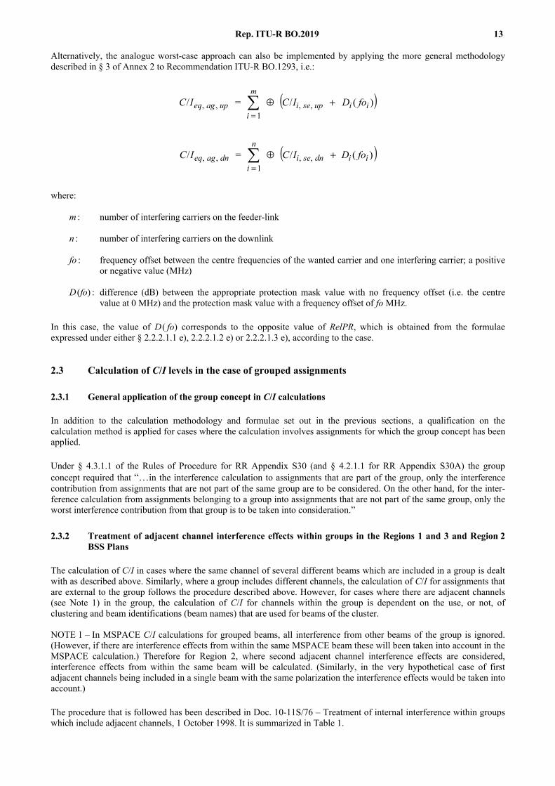
The masks appearing in Doc. 10-11S/138 are reproduced below in Figs. 2 and 3.
Figure 2 compares the masks with the PRs and masks of the BSS Plan for Regions 1 and 3 as contained in RR Appendices S30 (Annexes 5 and 6) and S30A (Annex 3).
Figure 3 performs a similar comparison for Region 2 (RR Appendix S30, Annex 5).
In both cases, absolute PRs have been converted to relative values for the purposes of comparison with the masks. For example, for the Regions 1 and 3 Plan, the co-channel and adjacent-channel PRs are 31 dB and 15 dB respectively, which leads to two –16 dB points on Fig. 2 at ± 19.18 MHz (the adjacent channel spacing).
From both Figs. 2 and 3, it can be seen that the proposed masks, when compared with the BSS protection masks for Regions 1 and 3 and for Region 2, seem consistent with systems employing a frequency deviation of between 12 and 13.5 MHz/V.
The masks given in Figs. 2 and 3 could form the basis of a new recommendation for protection masks for interference between FM/TV emissions in the BSS. However, it should be noted that, in applying the mask to wide deviation systems, the effects of filtering may also need to be considered and that these effects would tend to reduce the levels of adjacent channel interference. In addition, the nature of the FM/TV interference for wide deviations may also need to be studied (i.e. a mask with multiple inflection points, such as that given for Region 2 in RR Appendix S30, Annex 5, Fig. 6, may be more appropriate).
The contribution from Italy proposes also co-channel and adjacent channel PRs for this type of interference, but as no description of the test conditions is made, it is proposed not to consider these results here.
At the JWP 10-11/S meeting in March 1996, a proposal from Croatia recommended that the relative PR should be replaced with a specific PR template, which then could be applied for frequency off-sets based on any co-channel PR template adopted at WRC-97.
20 Rep. ITU-R BO.2019
Rap 2019-02
3020100–10–20–30
0
–45
–35
–40
–25
–30
–15
–20
–5
–10
dB re
lativ
e to
PR 0
Frequency offset (MHz)
12 MHz/V13.5 MHz/V16 MHz/V18.8 MHz/V25 MHz/VAppendix S30A PRsAppendix S30 PRsAppendix S30 masks
FIGURE 2Comparison between SG 4 masks and the Regions 1 and 3 PRs masks
FIGURE Rap. 2019-02 = 14 CM
3.3 Protection of digital carriers against analogue carriers
The following results complete those given in § 3.1.12 of Report ITU-R BO.634.
Preliminary measurements have been made by a few administrations and organizations (EBU, EUTELSAT, France, Italy...).
Concerning interference from a standard PAL FM/TV signal into a QPSK 3/4 signal, several protection masks have been drawn for different frequency deviations. A co-channel PR of about 14 dB is envisaged in this particular case where interference corresponds to a 1 dB degradation on the objective C/N to obtain a bit error ratio (BER) of 2 × 10⁻⁴ after Viterbi decoding but before Reed Solomon (RS) decoding, and where colour bar pictures are used. After the RS decoding a quasi error free signal (i.e. less than 1 error event per hour) will result.

Rep. ITU-R BO.2019 21
Rap 2019-03
3020100–10–20–30
0
–45
–35
–40
–25
–30
–15
–20
–5
–10
dB re
lativ
e to
PR 0
Frequency offset (MHz)
12 MHz/V13.5 MHz/V16 MHz/V18.8 MHz/V25 MHz/VAppendix S30 PRsAppendix S30 masks
FIGURE 3Comparison between SG 4 masks and the Region 2 PRs masks
FIGURE Rap. 2019-03 = 14 CM
Recent measurements conducted by France (France Télécom) allowed to get protection masks for 22.7 MBd and 5.3 MBd (QPSK 3/4) carriers compliant with the intermediate data rate (IDR) specification (INTELSAT Earth Station Standard 308 (IESS 308)).
The interfering signal is a FM PAL 75% colour bars test signal. Frequency deviation is 22 MHz/V, energy dispersal 600 kHz peak-to-peak, IF filter BW is 36 MHz.
The protection mask in the case of a 5.3 MBd wanted signal has been plotted only for 1 dB degradation margin, this value seeming the best compromise between realistic C/I ratios and link budget degradation.
A superposition in the above first two graphics of the different masks using relative values instead of absolute ones on the vertical axis indicates that the shape of each mask is nearly always the same.
22 Rep. ITU-R BO.2019
Rap 2019-04
16
14
12
10
8
6
4
2
–2
0
50 55 60 65 70 75 80 85 90
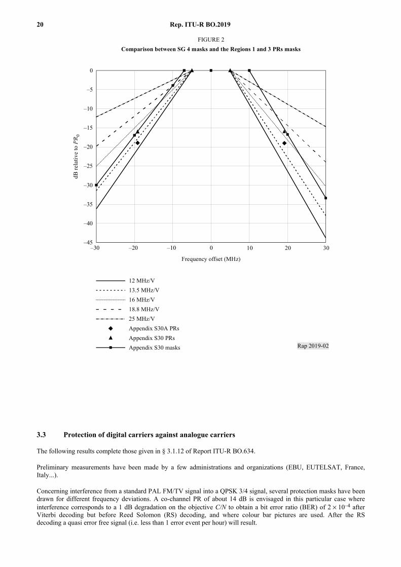
FIGURE 4Protection mask: PAL (22 MHz/V, 36 MHz, energy dispersal = 2 MHz peak-to-peak)
on digital for BER = 2 ×××× 10–4
C/I
(dB)
Wanted signal frequency (MHz) (interferer frequency = 70 MHz)
Degradation = 0.5 dB Degradation = 1 dB Degradation = 2 dB Degradation = 3 dB Degradation = 4 dB
FIGURE Rap. 2019-04 = 14 CM
Specific measurements were performed to show the impacts of different PAL FM TV signal parameters (frequency deviation, energy dispersal, sound subcarriers, image contents) on the protection masks of both wanted 22.7 MBd and 5.3 MBd (QPSK 3/4) digital signals (see Doc. 10-11S/1, ANNEX 2 to Annex 2). The frequency deviation and the image contents are the parameters that have a significant impact on the resulting masks. However, regarding the image contents, it should be noted that the protection masks can only be given for a realistic situation, i.e. for a mean TV signal such as the ITU-R test pattern. Therefore, the single remaining significant parameter is the frequency deviation.
These measurements confirm also the current formulae used to add several non-homogeneous interferers.
New protection masks are proposed for a 22.7 MBd (QPSK 3/4. degradation margin: 1 dB for BER = 2 × 10⁻⁴) digital signal against PAL FM TV signals with different frequency deviations, as well as the associated formula to be used for interference calculations:
The mask has two flanks of variable grade and a level central part of variable value. It can be approximated by a trapezoidal shape whose parameters are a function of frequency deviation.
Rep. ITU-R BO.2019 23
Rap 2019-05
17
15
13
11
9
7
5
3
–1
1
50 55 60 65 70 75 80 85 90
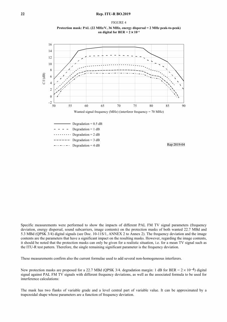
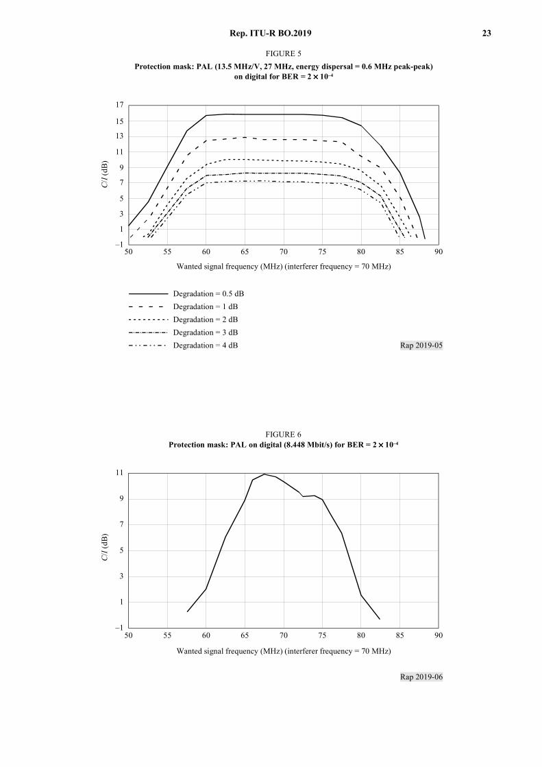
FIGURE 5Protection mask: PAL (13.5 MHz/V, 27 MHz, energy dispersal = 0.6 MHz peak-peak)
on digital for BER = 2 ×××× 10–4
C/I
(dB)
Wanted signal frequency (MHz) (interferer frequency = 70 MHz)
Degradation = 0.5 dB Degradation = 1 dB Degradation = 2 dB Degradation = 3 dB Degradation = 4 dB
FIGURE Rap. 2019-05 = 14 CM
Rap 2019-06
50 55 60 65 70 75 80 85 90–1
1
3
5
7
9
11
FIGURE 6Protection mask: PAL on digital (8.448 Mbit/s) for BER = 2 × × × × 10–4
C/I
(dB)
Wanted signal frequency (MHz) (interferer frequency = 70 MHz)
FIGURE Rap. 2019-06 = 14 CM
24 Rep. ITU-R BO.2019
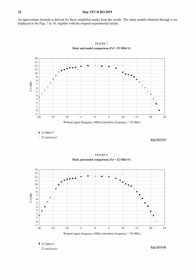
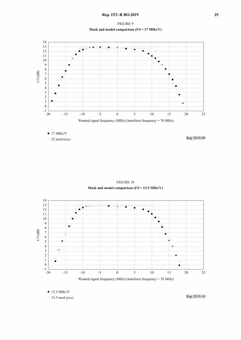
An approximate formula is derived for these simplified masks from the results. The mask models obtained through it are displayed in the Figs. 7 to 10, together with the original experimental results.
Rap 2019-07
–20 2015–5–10–15 105 250
0–1
123456789
1011121314
FIGURE 7Mask and model comparison (Fd = 25 MHz/V)
C/I
(dB)
Wanted signal frequency (MHz) (interferer frequency = 70 MHz)
25 MHz/V25 mod (exc)
FIGURE Rap. 2019-07 = 14 CM
Rap 2019-08
–20 2015–5–10–15 105 250
0–1
123456789
1011121314
FIGURE 8Mask and model comparison (Fd = 22 MHz/V)
C/I
(dB)
Wanted signal frequency (MHz) (interferer frequency = 70 MHz)
25 MHz/V22 mod (exc)
FIGURE Rap. 2019-08 = 14 CM
Rep. ITU-R BO.2019 25
Rap 2019-09
–20 2015–5–10–15 105 250
0–1
123456789
1011121314
FIGURE 9Mask and model comparison (Fd = 17 MHz/V)
C/I
(dB)
Wanted signal frequency (MHz) (interferer frequency = 70 MHz)
17 MHz/V22 mod (exc)
FIGURE Rap. 2019-09 = 14 CM
Rap 2019-10
–20 2015–5–10–15 105 250
0–1
123456789
1011121314
FIGURE 10Mask and model comparison (Fd = 13.5 MHz/V)
C/I
(dB)
Wanted signal frequency (MHz) (interferer frequency = 70 MHz)
13.5 MHz/V13.5 mod (exc)
FIGURE Rap. 2019-10 = 14 CM

26 Rep. ITU-R BO.2019
Empirical formulas for a protection mask model against analogue PAL interferer:
TABLE 3
These masks confirm as a maximum the above-mentioned 14 dB co-channel PR and propose adjacent channel PRs lower than 6 dB.
For other types of digital modulation like QPSK 7/8, 8-PSK 2/3 or 8-PSK 5/6, Radiotelevisione Italiana (RAI) has shown that co-channel PRs of between 16 dB and 20 dB are foreseen.
For the associated adjacent channel PRs, values lower than those defined in RR Appendix S30 (15 dB) are foreseen, however further studies are required in order to confirm this assumption.
EUTELSAT has performed similar measurements to those performed by France for 2, 8 and 34 Mbit/s digital carriers, investigating the effect of parameters such as energy dispersal, frequency deviation, picture content, number of sound subcarriers and code rate (Doc. 10-11S/27).
The results obtained for a 22.7 MBd digital carrier are generally consistent with those shown above. The slope of the proposed masks agree with the results reasonably well for the range of frequency offsets shown above, however for larger frequency offsets they tend to be slightly pessimistic. A comparison of the two sets of results showed a similar shape but with a slight frequency offset between them which is thought to be due to measurement tolerances. The EUTELSAT results have shown that the measurement results also have a dependence on the filtering implemented in the digital modem.
The EUTELSAT studies have indicated that the shape of the PR mask is not very sensitive to the level of degradation due to interference. This is in agreement with the findings of France. It is, however, very sensitive to the picture content which confirms the requirement to determine masks for an average picture for planning purposes. The results are also dependent upon the number and level of the subcarriers transmitted on the FM TV carrier for the lower symbol rates and large frequency offsets. They are also dependent upon the filtering applied at the output of the FM modulator. For the higher symbol rates (e.g. 22.7 MBd) the subcarriers have no significant influence on the PR mask. The effect of applying different code rates to a constant symbol rate carrier for the same interfering signal is to shift the measured PR mask on the C/I axis by an amount which is equivalent to the difference in the coding gains. This is further evidence that a general mask could be developed taking into account the coding gain as one of the parameters.
A contribution from Australia (Doc. 10-11S/91 (Add.1)) observes that, whilst available test results are based upon the use of a 75% colour bar as the wanted signal, pictures with higher colour saturation can occur in practice (e.g. captions and computer-generated graphics). Such pictures would lead to worse interference at high frequency offsets with respect to that obtained with a 75% colour bar signal. However, since such scenes occur infrequently in normal picture material, deriving PR masks on the basis of 100% colour saturation would result in unrealistically stringent requirements and hence an over-engineering of the Plans. The 75% level of colour saturation is widely assumed in transmission testing to represent the spectral characteristics of normal picture material and is therefore also considered to be appropriate here. Several sets of results are now available for a range of symbol rates which should allow the development of a general mask whose parameters are a function of the symbol rate, the interfering signal’s frequency deviation and the code rate. The range of symbol rates for which the mask is applicable also needs to be established.
Leading slope (wanted signal frequency < interferer frequency) Level part Trailing slope (wanted signal
frequency > interferer frequency)
C/I = a F + b where:
a = –0.072 Fd + 2.777
b = –0.947 Fd + 46.6
C/I = –0.06 Fd + 13.703 C/I = a F + b where:
a = + 0.064 Fd – 2.488
b = –0.691 Fd + 39.133
Fd: frequency deviation. F: frequency offset = wanted signal frequency – interferer frequency.

Rep. ITU-R BO.2019 27
3.4 Protection between digital carriers
The following results complete those given in § 3.1.13 of Report ITU-R BO.634.
Significant differences exist on the PR mask obtained in comparison with the analogue into digital interference situation.
The resulting PRs depend on the level of degradation allowed on the C/N to obtain a given BER, the type of modulation and channel coding used.
French measurements provided in Doc. 10-11S/1 (ANNEX 2 to Annex 2) confirm that the power of white Gaussian noise and the power of digital interferer can be simply added, provided that interferer power is not predominant in this addition. In addition, protection masks for different levels of degradation (0.5 dB, 1 dB, 2 dB, 3 dB and 4 dB) allowed on the C/N of a given 22.7 MBd (QPSK 3/4) digital signal by another 22.7 MBd (QPSK 3/4) digital signal are proposed:
An IF loop is constituted with a 22.7 MBd (QPSK 3/4) IDR (IESS 308) compliant modulator and demodulator. A pseudo-random binary sequence (PRBS) generator is incorporated in the modulator, a BER counter provides directly the quality of the signal received by the demodulator. The convolutional code used has a 3/4 (fixed) rate (For a BER = 2 × 10⁻⁴, the modem used requires an Eb/N0 in IF loop of around 4.85 dB.)
Rap 2019-11
16
14
12
10
8
6
4
2
–2
0
50 55 60 65 70 75 80 85 90 95
FIGURE 11Protection mask: digital on digital for BER = 2 ×××× 10–4
C/I
(dB)
Interferer frequency (MHz) (wanted signal = 70 MHz)
Degradation = 0.5 dB Degradation = 1 dB Degradation = 2 dB Degradation = 3 dB Degradation = 4 dB
FIGURE Rap. 2019-11 = 14 CM
The interferer is another IDR 22.7 MBd (QPSK 3/4) carrier generated by a modulator using its internal PRBS generator. Its sequence and that of the measured signal are uncorrelated.
Each curve plots minimum value of C/I against interferer frequency, for a given margin (0.5 to 4 dB).
This means that, if the link budget allows a 1 dB loss for interference, the ratio between carrier and interferer should be superior to that plotted on the 1 dB margin curve for the considered frequency, in order to obtain a BER better than 2 × 10⁻⁴.
These new masks confirm that the above-mentioned co-channel and adjacent channel PRs can be applied with comfortable margins.

28 Rep. ITU-R BO.2019
The interfering signal is usually treated as a white noise uniformly distributed in its occupied bandwidth. Interferer power is thus calculated as the fraction of power in the partial bandwidth intersecting that of the useful signal.
True interferer power is calculated (on the assumption that C/N + I remains constant for a given BER) and its variation against frequency offset is plotted for various values of thermal noise. The other curve shows the theoretical variation for a uniformly distributed signal.
Rap 2019-12
0–20 –10 10 20 30
2
–20
–4–6–8
–10–12–14–16–18
FIGURE 12C/I variation (dB)
C/I
(dB)
Frequency offset (MHz)
0.5 dB margin1 dB margin2 dB margin3 dB margin4 dB marginTheory
FIGURE Rap. 2019-12 = 14 CM
The actual variation is much steeper than the theoretical one. This result demonstrates the need to introduce a correction factor depending upon frequency offset, if this approach to interference calculation is still to be used.
This result has been confirmed by measurements presented in a further contribution from France (France’ Contribution to the Rapporteur’s Group, March 1996) dealing with 8 Mbit/s carriers.
A contribution from Australia (see Doc. 10-11S/91 (Add.1)) considers the possible consequences, as far as interference calculation methods are concerned, of the use of narrow-band digital satellite signals in the BSS.
For narrow-band digital interference into wideband digital signals, it is suggested that the approach of modelling the interference as noise is a reasonable assumption (i.e. to calculate the interference effect as a ratio of the overlapping occupied bandwidths). The same conclusion applies for the converse case (wideband interference into narrow-band digital signals) and for the case of narrow-band digital interference into narrow-band digital signals.
For narrow-band digital carriers interfering into other narrow-band digital carriers, it might be possible to interleave the frequencies of such carriers during the planning process in order to minimize the mutual interference between them. Other effects, specifically the intermodulation noise arising from the use of multiple narrow-band carriers within a single transponder, may also need to be taken into account.
Studies performed by the United States of America confirm that the interference can be modelled as noise-like, provided that the interference power is not predominant. Doc. 10-11S/156 – Preliminary analysis of co-channel digital-to-digital protection ratios for a variety of modulation formats, 14 May 1999, indicates that power addition is conservative,
Rep. ITU-R BO.2019 29
provided that the ratio of the interference power to the noise power, I/N, is less than –2 dB. At higher values of I/N, power addition underestimates the effect of interference. This deviation from noise-like behaviour is thought to be due to cycle slipping phenomena in the receiver’s synchronisation loops. These observations are based on simulations of interference between 16-quadrature amplitude modulation (16-QAM) carriers. QAM carriers were chosen for this study rather than phase shift keying (PSK) as a more stringent test of the hypothesis that the digital interference is noise-like.
Annex 1 to Recommendation ITU-R BO.1293 describes a method for calculating protection masks for interference between various types of digital carrier. The calculation method is based on the assumption of a linear satellite channel. Further studies are requested in Recommendation ITU-R BO.1293 to quantify the effects of the non-linear channel.
In the non-linear satellite channel, high power amplification of the interfering signal causes spectral side-lobe re-growth. The interference contributed by the side-lobes is negligible when the frequency offset between the wanted and interfering signals is small, but becomes increasingly significant as the frequency offset is increased.
At the May 1999 meeting of JWP 10-11S, the calculation method of Annex 1 to Recommendation ITU-R BO.1293 was revised to take account of the effects of digital signal transmission through a non-linear satellite channel. The revisions were based on information contained in Doc. 10-11S/138. The revisions to Recommendation ITU-R BO.1293 are given in Doc. 11/109 (Rev.1) – Proposed revisions to Recommendation ITU-R BO.1293: Protection masks and associated calculation methods for interference into broadcast satellite systems involving digital emissions, 29 June 1999.
The revised calculation method uses the basic algorithm defined in Annex 1 to Recommendation ITU-R BO.1293. It applies this algorithm two more times with respect to the calculation method for the linear channel, once for the first spectral side-lobe and once for the second spectral side-lobe of the interfering digital carrier. The level of each side-lobe is adjusted to reflect the principal characteristics of the non-linear transmission channel, namely the power transfer characteristics of the high power amplifier (HPA), its operating point (back-off) and the side-lobe attenuation due to post-HPA filtering.
The accuracy of the revised calculation method is demonstrated in Doc. 10-11S/138, which compares calculation results with those obtained by simulation for typical broadcast digital carriers. There is good agreement between the two sets of results, although the post-HPA filtering is conservatively estimated in the calculation method. This is in view of the fact that the characteristics of the post-HPA filter will vary from system to system. Doc. 10-11S/138 also suggests appropriate values for the input parameters of the revised calculation method (relative side-lobe levels and side-lobe attenuation due to post-HPA filtering).
3.5 Common conclusion on the protection of digital signals
First results show that co-channel PRs are closed to those mentioned in § 3.3 (between 14 dB and 18 dB). A more significant difference exists for the adjacent channel PRs.
Analogue or digital interference levels into wanted digital carriers are directly related to the level of degradation on the objective C/N allowed for interference. This means that the higher the thermal C/N is, the higher the interference into the digital system could be regarding a given C/(N + I) critical threshold to respect.
Thus, it is proposed to establish a reference for the level of degradation allowed for interference into digital carriers before fixing PR values.
However, it is also the view of this group that regarding the first PR values presented in § 3.3 and 3.4, a co-channel PR of about 20 dB and an adjacent channel PR of about 15 dB can be foreseen with no difficulty as they should correspond to an important allowance on the degradation of the C/N.
The results obtained at the end of § 3.3 and 3.4 for the protection of digital carriers show that the difference between the co-channel PR and a given frequency offset PR, for a given set of modulation parameters, is not related to the level of degradation allowed for interference on the objective C/N.
Therefore, for each set of modulation parameters, a single protection mask for a given level of degradation (e.g. 1 dB) needs to be established. The protection mask related to a different level of degradation is then obtained by shifting the above reference model from the reference co-channel PR to the new co-channel PR associated to this different level of degradation.

30 Rep. ITU-R BO.2019
4 Compatibility between BSS transmissions and space operation systems
RR Appendix S30 provides for the use of the bands 11.7-12.5 GHz in Region 1 and 11.7-12.2 GHz in Region 3 by assigning channels to the administrations in those Regions for satellite broadcasting, but no specific assignments were made for maintenance telemetering, tracking and telecommand (TTC) (although Annex 5 to Appendix S30 specifies guardbands at the edges of both bands). Consequently it may be difficult to use these bands for maintenance teleme-tering, tracking or telecommand (some potential difficulties involved in this particular implementation of the space operation function are discussed in Report ITU-R BO.1076). The purpose of the guardbands in the RR Appendices S30 and S30A Plans is mainly to limit the spurious emissions of the BSS systems in order to protect the services in the adjacent frequency bands.
The BR has reported to JWP 10-11S that due to the lack of any specific procedure, the Radio Regulations Board (RRB) decided that frequency assignments in the guardbands of the Plans are subject to advance publications. No other technical examination is effected, however.
The BR has reported also that in their proposed modification/addition to the Plans, some Administrations, due to the use of different bandwidths and centre frequencies from those in the Plan, overlap the guardbands of the Plans and therefore may affect the TTC spacecraft service functions that are operating in these guardbands.
In the meantime, whenever, the BR finds that a proposed modification of RR Appendices S30 and S30A Plans involves frequency assignments which overlap with the guardbands, it includes a note in the Special Section and draws the attention of administrations likely to be affected to provide comments within four months of publication.
The following text describes the guardbands as currently defined in RR Appendices S30 and S30A and considers the possibility of a redefinition (reduction) of these guardbands in order to increase the flexibility in the Plans, based on a revision of the assumptions originally used in their definition (Doc. 10-11S/57 (Add.1)). Furthermore, in order to assess the compatibility of BSS transmissions in the RR Appendices S30 and S30A guardbands with the space operation service, the group has considered the information available in the Reports and Contributions (see Report ITU-R BO.807; Report ITU-R BO.1076; Docs 10-11S/153; 10-11S/178; 10-11S/8; 10-11S/9; 10-11S/26, and 10-11S/35) and proposes guidance in § 4.3 for administrations that are intending to use the RR Appendices S30 and S30A guardbands to operate such services.
4.1 Guardbands defined in RR Appendices S30 and S30A
The guardbands of the BSS Plans are defined in § 3.9 to Annex 5 of RR Appendix S30 and § 3.1 to Annex 3 of RR Appendix S30A.
The assumptions taken to establish these guardbands at the lower and upper edges of the BSS band were as follows (see § 3.9.2 to Annex 5 of RR Appendix S30): a maximum beam centre satellite e.i.r.p. of 67 dBW for the BSS system, a filter roll-off of 2 dB/MHz and a 39 dBW e.i.r.p. for the FSS systems in the adjacent frequency bands. This leads to a 14 MHz guardband, where available.
TABLE 4
Region
Guardband at the lower edge of the band
(MHz)
Guardband at the upper edge of the band
(MHz)
Downlink at 12 GHz 1 3
14 14
11 17.88
Feeder-link at 14 GHz 1 and 3 11.8 11.86
Feeder-link at 17 GHz 1 and 3 14 11
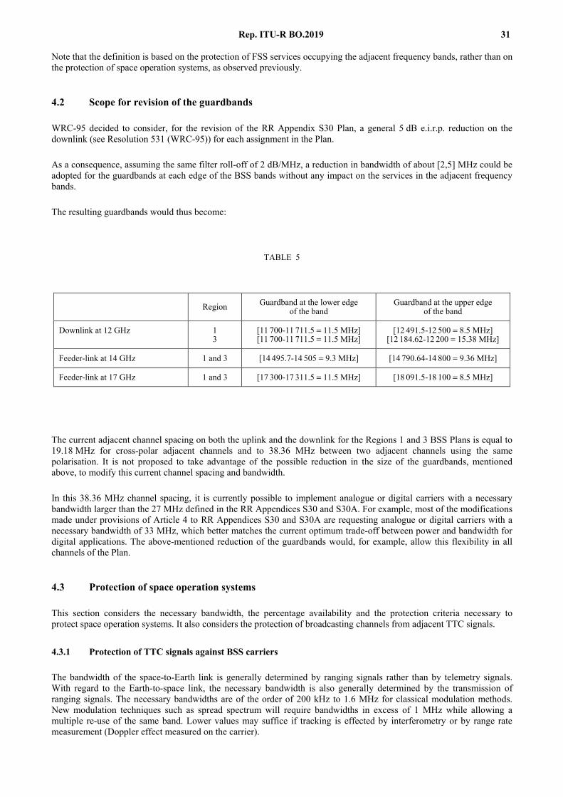
Rep. ITU-R BO.2019 31
Note that the definition is based on the protection of FSS services occupying the adjacent frequency bands, rather than on the protection of space operation systems, as observed previously.
4.2 Scope for revision of the guardbands
WRC-95 decided to consider, for the revision of the RR Appendix S30 Plan, a general 5 dB e.i.r.p. reduction on the downlink (see Resolution 531 (WRC-95)) for each assignment in the Plan.
As a consequence, assuming the same filter roll-off of 2 dB/MHz, a reduction in bandwidth of about [2,5] MHz could be adopted for the guardbands at each edge of the BSS bands without any impact on the services in the adjacent frequency bands.
The resulting guardbands would thus become:
TABLE 5
The current adjacent channel spacing on both the uplink and the downlink for the Regions 1 and 3 BSS Plans is equal to 19.18 MHz for cross-polar adjacent channels and to 38.36 MHz between two adjacent channels using the same polarisation. It is not proposed to take advantage of the possible reduction in the size of the guardbands, mentioned above, to modify this current channel spacing and bandwidth.
In this 38.36 MHz channel spacing, it is currently possible to implement analogue or digital carriers with a necessary bandwidth larger than the 27 MHz defined in the RR Appendices S30 and S30A. For example, most of the modifications made under provisions of Article 4 to RR Appendices S30 and S30A are requesting analogue or digital carriers with a necessary bandwidth of 33 MHz, which better matches the current optimum trade-off between power and bandwidth for digital applications. The above-mentioned reduction of the guardbands would, for example, allow this flexibility in all channels of the Plan.
4.3 Protection of space operation systems
This section considers the necessary bandwidth, the percentage availability and the protection criteria necessary to protect space operation systems. It also considers the protection of broadcasting channels from adjacent TTC signals.
4.3.1 Protection of TTC signals against BSS carriers
The bandwidth of the space-to-Earth link is generally determined by ranging signals rather than by telemetry signals. With regard to the Earth-to-space link, the necessary bandwidth is also generally determined by the transmission of ranging signals. The necessary bandwidths are of the order of 200 kHz to 1.6 MHz for classical modulation methods. New modulation techniques such as spread spectrum will require bandwidths in excess of 1 MHz while allowing a multiple re-use of the same band. Lower values may suffice if tracking is effected by interferometry or by range rate measurement (Doppler effect measured on the carrier).
Region Guardband at the lower edge of the band
Guardband at the upper edge of the band
Downlink at 12 GHz 1 3
[11 700-11 711.5 = 11.5 MHz] [11 700-11 711.5 = 11.5 MHz]
[12 491.5-12 500 = 8.5 MHz] [12 184.62-12 200 = 15.38 MHz]
Feeder-link at 14 GHz 1 and 3 [14 495.7-14 505 = 9.3 MHz] [14 790.64-14 800 = 9.36 MHz]
Feeder-link at 17 GHz 1 and 3 [17 300-17 311.5 = 11.5 MHz] [18 091.5-18 100 = 8.5 MHz]

32 Rep. ITU-R BO.2019
The reference bandwidth in which the protection level or ratio must be specified depends on the characteristics of the receivers used and their susceptibility to continuous wave, amplitude modulated or low-modulation-index phase-modulated interferences. Phase-locked receivers are often used; in such cases the reaction of the receiver to a narrow-band interfering source is characterized by the equivalent noise bandwidth of the loop. This bandwidth is normally fixed at a value between a few hundred hertz and a few kilohertz. A value of 1 kHz may therefore be adopted for the reference bandwidth.
Generally the percentage of time during which space operation links can tolerate an interference level above the protection level may be fixed at 1% each day. This value is based on the assumption that the spacecraft is equipped with memory and automatic devices to ensure its safety during interruptions of telecommunications. This condition was not always fulfilled in the past, but it is considered reasonable to require it to be met by future systems.
However interference lasting for as long as 15 consecutive minutes is intolerable during certain foreseeable critical stages, such as launch phases, critical spacecraft manoeuvres, or for such short-lived spacecraft as rocket probes. It would be unreasonable to lay down protection criteria on the basis of such exceptional situations, and it would be preferable to invite concerned administrations to carry out special analyses of the interference likely to be caused and to take countermeasures which should be temporary and limited to specific regions.
The power of earth station transmitters can generally be increased within the limits imposed by the Radio Regulations, therefore on-board TTC receivers do not always operate at maximum sensitivity. The protection of space station receivers is therefore more conveniently expressed by PRs rather than by protection levels. For feeder-links, main interference tests have been conducted in France. With the television signals available in the laboratory, tests have shown that the following PR is necessary for a TTC signal at the edge of the feeder-link channel (nominal frequency separation between TTC and feeder-link signal equals 13.5 MHz):
PTTC / PTV ≥ –27 dB
where:
PTTC : carrier power of the TTC signal at the input of the TTC satellite receiver input
PTV : carrier power of the feeder-link signal at the TTC satellite receiver input.
Consequently, for space stations carrying out space operation functions, the ratio of signal power to total interference power should not fall below –27 dB for a period exceeding 1% of the time each day.
For the downlink, attempts are generally made to reduce the necessary power of on-board transmitters to a minimum and earth station receivers therefore have to operate at maximum sensitivity. In this case, it may be more appropriate to express the protection requirement as a protection level rather than as a PR.
Above 1 GHz, it is considered that the total noise temperature of earth stations is 100 K or more which, at the receiver input, is equivalent to a noise power spectral density of kT = –208.6 dB (W/Hz). It is further considered that, in most cases, additional protection of about 5 dB is required against all types of interference. Following this approach, the total interference power spectral density must therefore not exceed –214 dB(W/Hz) at the receiver input. Consequently, for earth stations carrying out space operation functions, the total interference power at the receiver input in any 1 kHz band should not exceed –184 dBW for more than 1% of the time each day.
Nevertheless, the problem of interference on the downlink is more complex than this analysis suggests because of intermodulation products in the satellite repeater and other interference sources. Further studies are required. Provisionally, the protection requirements derived for feeder-link interference may also be applied to the downlink.

Rep. ITU-R BO.2019 33
4.3.2 Protection of adjacent broadcasting channels against TTC signals
TTC signals should in no case impair broadcasting transmissions. Regarding the feeder links, tests carried out in France showed that the PR of the adjacent channels against the sum of interfering TTC carriers should be equal to 20 dB:
PTV / (PTTC)total ≥ 20 dB
where:
PTV : carrier power of the adjacent channel signal at the payload receiver input
(PTTC)total : carrier power of the interfering TTC carriers at the payload receiver input.
However, due to the abrupt decrease in the effect of the interference with increasing frequency separation between broadcasting and TTC signals, it has been demonstrated that the following ratio is sufficient:
PTV / PTTC ≥ 26 dB
where PTTC is the power of a single TTC interferer carrier at the payload receiver input. Further studies are still required to confirm this value.
4.4 Operational aspects
A comparison is given below of the advantages and disadvantages of the use for space operation functions of mission frequency bands and frequency bands allocated to the space operation service or a combination of the two.
4.4.1 Use of mission bands for space operation
4.4.1.1 Advantages
Since most spacecraft are equipped with transmitters and receivers for telecommunications directly concerned with their mission, it is generally preferable to use the same equipments for maintenance TTC, in order to reduce the cost of on-board and earth station equipment and to economize the spectrum.
4.4.1.2 Disadvantages
Experience shows that this mode of operation is not always the best:
– when frequencies above 7 GHz are used for mission telecommunications, it is often difficult to ensure on board the spacecraft the necessary radiation pattern to guarantee maintenance of links during launching and during nominal attitude loss phases;
– in certain frequency bands allocated to mission telecommunications, the allotment plans do not provide specifically for the transmission of space operation data;
– economy of on-board equipment is less than it appears at first sight in those cases where it becomes necessary to install a wide-coverage antenna system for space operation functions in addition to the directional radiation antennas usually used for mission telecommunications;
– economy of earth station equipment is also not necessarily guaranteed, since space operation functions may necessitate a geographical location of stations different from that required for mission functions.
4.4.2 Use of specific space operation service bands
4.4.2.1 Advantages
In view of all the expenditure on board and on the ground, it may be cheaper to have a single network of earth stations for space operation. These would operate with satellites carrying out missions for several services to which different frequency bands are allocated. The common network would use frequencies allocated specifically to the space operation service.
4.4.2.2 Disadvantages
The advantage of a multi-purpose earth station network using frequencies allocated exclusively to the space operation service and working with several spacecraft is limited if some of the spacecraft require the permanent operation of telemetry links, which would make it necessary to increase the number of earth stations. This would reduce, particularly for geostationary satellites, the efficient use of frequencies and increase the interference potential.

34 Rep. ITU-R BO.2019
4.4.3 Combined use of mission and specific frequency bands
In conclusion, the best solution, especially for mission telecommunications using frequencies above 8 GHz, may be to equip spacecraft with two maintenance TTC, one operating in the band allocated to the mission and the other in the frequency band which is most suitable for space operations, i.e., the band 1-8 GHz. The first system would be used preferably in the routine phases and could be brought into operation by mission telecommunication earth stations or by a specialized earth station; the second system would be used during the launch phase and during other critical phases, without unduly overloading the multi-purpose earth station network. The additional cost of the on-board equipment is less than might appear at first sight, because the telemetry encoder and the telecommand decoder would not have to be duplicated and because the on-board antennas would have to be duplicated in any case to ensure the necessary coverage during critical phases. The additional cost of ground equipment would be shared between the user systems. To offset these additional investments, this solution would ensure the greatest operational reliability and flexibility at all phases of the mission without entailing any appreciable increase in operational costs.
5 Interference between FSS transmissions and BSS assignments
5.1 Interference from FSS transmissions into BSS assignments
When BSS assignments are used for FSS transmissions, it is assumed that these assignments may not cause more interference than BSS transmissions operating in conformity with the Plan. This section presents limits on the power levels of FSS transmissions with respect to BSS transmissions (analogue or digital) in order to satisfy this criterion.
The interference possibilities are shown in the Table 6 (see Doc. 10-11S/45). Table 6 covers co-channel and adjacent channel cases only. For other frequency spacings, and for the different possible carrier types, on-going work on PR templates should be further reflected in the table.
In Table 6, it is assumed that the BSS plan entry was designated for analogue FM/TV or Digital TV (columns 2 and 3). Column 1 identifies the FSS usage to which such a channel is to be put.
In the case of co-channel interference, the requirement that the FSS transmission causes no more interference than a BSS transmission would be satisfied if the FSS interference power is less than or equal to the BSS power.
In the case of adjacent channel interference, consideration of using a digital signal instead of an analogue signal is given in § 3.1. Using the same approach for FSS digital signals:
PFSS ≤ PBSS – ∆ – 10 log (b/B) + K dBW
where:
B : bandwidth of the analogue TV carrier
b : bandwidth of the overlapping spectrum
K : digital/analogue correction factor (see § 3.1)
∆ : difference between co- and adjacent channel PRs = 8 dB.
For wideband digital systems of 27 MHz necessary bandwidth:
B = 27 MHz and b = 7.82 MHz
PFSS ≤ PBSS – 2.6 + K dBW
For narrow-band digital systems, each of n carriers within the overlapping bandwidth permitted the same interference value, resulting in:
PFSS ≤ PBSS – 8 – 10 log n + K dBW
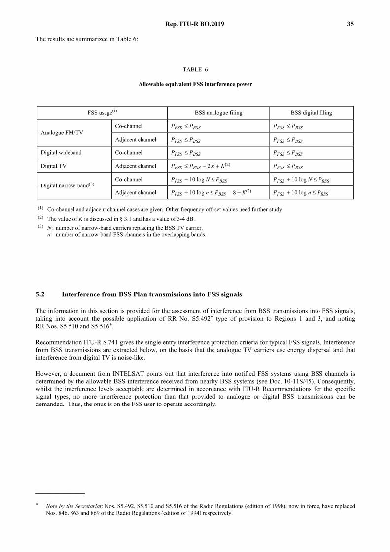
Rep. ITU-R BO.2019 35
The results are summarized in Table 6:
TABLE 6
Allowable equivalent FSS interference power
5.2 Interference from BSS Plan transmissions into FSS signals
The information in this section is provided for the assessment of interference from BSS transmissions into FSS signals, taking into account the possible application of RR No. S5.492* type of provision to Regions 1 and 3, and noting RR Nos. S5.510 and S5.516*.
Recommendation ITU-R S.741 gives the single entry interference protection criteria for typical FSS signals. Interference from BSS transmissions are extracted below, on the basis that the analogue TV carriers use energy dispersal and that interference from digital TV is noise-like.
However, a document from INTELSAT points out that interference into notified FSS systems using BSS channels is determined by the allowable BSS interference received from nearby BSS systems (see Doc. 10-11S/45). Consequently, whilst the interference levels acceptable are determined in accordance with ITU-R Recommendations for the specific signal types, no more interference protection than that provided to analogue or digital BSS transmissions can be demanded. Thus, the onus is on the FSS user to operate accordingly.
_______________
* Note by the Secretariat: Nos. S5.492, S5.510 and S5.516 of the Radio Regulations (edition of 1998), now in force, have replaced Nos. 846, 863 and 869 of the Radio Regulations (edition of 1994) respectively.
FSS usage(1) BSS analogue filing BSS digital filing
Co-channel PFSS ≤ PBSS PFSS ≤ PBSS Analogue FM/TV
Adjacent channel PFSS ≤ PBSS PFSS ≤ PBSS
Digital wideband Co-channel PFSS ≤ PBSS PFSS ≤ PBSS
Digital TV Adjacent channel PFSS ≤ PBSS – 2.6 + K(2) PFSS ≤ PBSS
Co-channel PFSS + 10 log N ≤ PBSS PFSS + 10 log N ≤ PBSS Digital narrow-band(3)
Adjacent channel PFSS + 10 log n ≤ PBSS – 8 + K(2) PFSS + 10 log n ≤ PBSS
(1) Co-channel and adjacent channel cases are given. Other frequency off-set values need further study. (2) The value of K is discussed in § 3.1 and has a value of 3-4 dB. (3) N: number of narrow-band carriers replacing the BSS TV carrier.
n: number of narrow-band FSS channels in the overlapping bands.
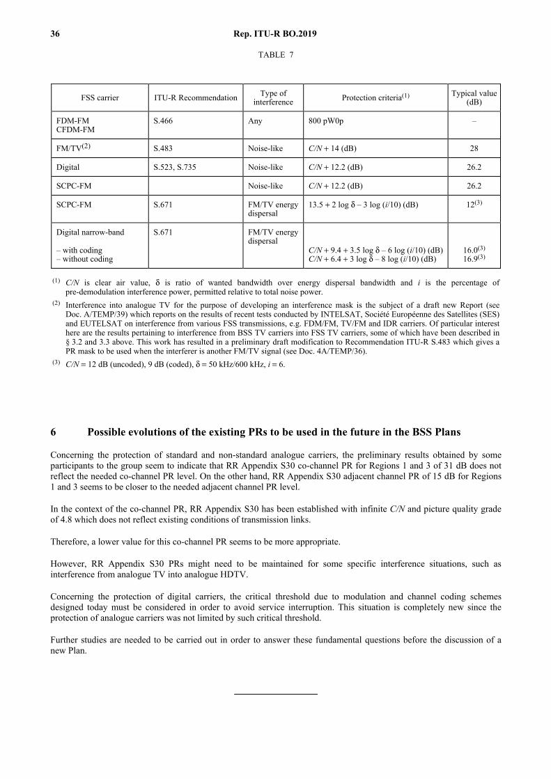
36 Rep. ITU-R BO.2019
TABLE 7
6 Possible evolutions of the existing PRs to be used in the future in the BSS Plans
Concerning the protection of standard and non-standard analogue carriers, the preliminary results obtained by some participants to the group seem to indicate that RR Appendix S30 co-channel PR for Regions 1 and 3 of 31 dB does not reflect the needed co-channel PR level. On the other hand, RR Appendix S30 adjacent channel PR of 15 dB for Regions 1 and 3 seems to be closer to the needed adjacent channel PR level.
In the context of the co-channel PR, RR Appendix S30 has been established with infinite C/N and picture quality grade of 4.8 which does not reflect existing conditions of transmission links.
Therefore, a lower value for this co-channel PR seems to be more appropriate.
However, RR Appendix S30 PRs might need to be maintained for some specific interference situations, such as interference from analogue TV into analogue HDTV.
Concerning the protection of digital carriers, the critical threshold due to modulation and channel coding schemes designed today must be considered in order to avoid service interruption. This situation is completely new since the protection of analogue carriers was not limited by such critical threshold.
Further studies are needed to be carried out in order to answer these fundamental questions before the discussion of a new Plan.
FSS carrier ITU-R Recommendation Type of interference Protection criteria(1) Typical value
(dB)
FDM-FM CFDM-FM
S.466 Any 800 pW0p –
FM/TV(2) S.483 Noise-like C/N + 14 (dB) 28
Digital S.523, S.735 Noise-like C/N + 12.2 (dB) 26.2
SCPC-FM Noise-like C/N + 12.2 (dB) 26.2
SCPC-FM S.671 FM/TV energy dispersal
13.5 + 2 log δ – 3 log (i/10) (dB) 12(3)
Digital narrow-band
– with coding – without coding
S.671 FM/TV energy dispersal
C/N + 9.4 + 3.5 log δ – 6 log (i/10) (dB) C/N + 6.4 + 3 log δ – 8 log (i/10) (dB)
16.0(3) 16.9(3)
(1) C/N is clear air value, δ is ratio of wanted bandwidth over energy dispersal bandwidth and i is the percentage of pre-demodulation interference power, permitted relative to total noise power.
(2) Interference into analogue TV for the purpose of developing an interference mask is the subject of a draft new Report (see Doc. A/TEMP/39) which reports on the results of recent tests conducted by INTELSAT, Société Européenne des Satellites (SES) and EUTELSAT on interference from various FSS transmissions, e.g. FDM/FM, TV/FM and IDR carriers. Of particular interest here are the results pertaining to interference from BSS TV carriers into FSS TV carriers, some of which have been described in § 3.2 and 3.3 above. This work has resulted in a preliminary draft modification to Recommendation ITU-R S.483 which gives a PR mask to be used when the interferer is another FM/TV signal (see Doc. 4A/TEMP/36).
(3) C/N = 12 dB (uncoded), 9 dB (coded), δ = 50 kHz/600 kHz, i = 6.


![ShuaiYang, for the STAR Collaboration•Indication of interference structure •Similar slope parameter ØEnhancement can not be described by broaden -model calculation [3] ØNeed](https://img.pdfslide.net/doc/110x75/6034ede9740c5d77f67051b7/shuaiyang-for-the-star-collaboration-aindication-of-interference-structure-asimilar.jpg)