Embed Size (px)
Citation preview
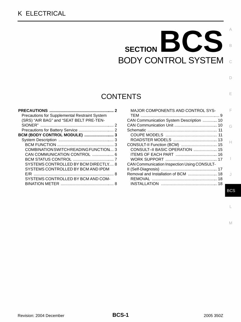
BCS-1
BODY CONTROL SYSTEM
K ELECTRICAL
CONTENTS
C
D
E
F
G
H
I
J
L
M
SECTION BCSA
B
BCS
Revision: 2004 December 2005 350Z
BODY CONTROL SYSTEM
PRECAUTIONS .......................................................... 2Precautions for Supplemental Restraint System (SRS) “AIR BAG” and “SEAT BELT PRE-TEN-SIONER” .................................................................. 2Precautions for Battery Service ................................ 2
BCM (BODY CONTROL MODULE) ........................... 3System Description .................................................. 3
BCM FUNCTION ................................................... 3COMBINATION SWITCH READING FUNCTION ..... 3CAN COMMUNICATION CONTROL .................... 6BCM STATUS CONTROL ..................................... 7SYSTEMS CONTROLLED BY BCM DIRECTLY ..... 8SYSTEMS CONTROLLED BY BCM AND IPDM E/R ........................................................................ 8SYSTEMS CONTROLLED BY BCM AND COM-BINATION METER ................................................ 8
MAJOR COMPONENTS AND CONTROL SYS-TEM ....................................................................... 9
CAN Communication System Description .............. 10CAN Communication Unit ....................................... 10Schematic ............................................................... 11
COUPE MODELS ............................................... 11ROADSTER MODELS ........................................ 13
CONSULT-II Function (BCM) ................................. 15CONSULT–II BASIC OPERATION ...................... 15ITEMS OF EACH PART ...................................... 16WORK SUPPORT ............................................... 17
CAN Communication Inspection Using CONSULT-II (Self-Diagnosis) ................................................... 17Removal and Installation of BCM ........................... 18
REMOVAL ........................................................... 18INSTALLATION ................................................... 18

BCS-2
PRECAUTIONS
Revision: 2004 December 2005 350Z
PRECAUTIONS PFP:00001
Precautions for Supplemental Restraint System (SRS) “AIR BAG” and “SEAT BELT PRE-TENSIONER” AKS008YT
The Supplemental Restraint System such as “AIR BAG” and “SEAT BELT PRE-TENSIONER”, used alongwith a front seat belt, helps to reduce the risk or severity of injury to the driver and front passenger for certaintypes of collision. This system includes seat belt switch inputs and dual stage front air bag modules. The SRSsystem uses the seat belt switches to determine the front air bag deployment, and may only deploy one frontair bag, depending on the severity of a collision and whether the front occupants are belted or unbelted.Information necessary to service the system safely is included in the SRS and SB section of this Service Man-ual.WARNING:● To avoid rendering the SRS inoperative, which could increase the risk of personal injury or death
in the event of a collision which would result in air bag inflation, all maintenance must be per-formed by an authorized NISSAN/INFINITI dealer.
● Improper maintenance, including incorrect removal and installation of the SRS, can lead to per-sonal injury caused by unintentional activation of the system. For removal of Spiral Cable and AirBag Module, see the SRS section.
● Do not use electrical test equipment on any circuit related to the SRS unless instructed to in thisService Manual. SRS wiring harnesses can be identified by yellow and/or orange harnesses orharness connectors.
Precautions for Battery Service AKS003RC
Before disconnecting the battery, lower both the driver and passenger windows. This will prevent any interfer-ence between the window edge and the vehicle when the door is opened/closed. During normal operation, thewindow slightly raises and lowers automatically to prevent any window to vehicle interference. The automaticwindow function will not work with the battery disconnected.

BCM (BODY CONTROL MODULE)
BCS-3
C
D
E
F
G
H
I
J
L
M
A
B
BCS
Revision: 2004 December 2005 350Z
BCM (BODY CONTROL MODULE) PFP:284B2
System Description AKS00AV5
BCM (Body Control Module) controls the operation of various electrical units installed on the vehicle.
BCM FUNCTIONBCM has combination switch reading function for reading the operation of combination switches (light, wiper,washer and turn signal) in addition to a function for controlling the operation of various electrical components.Also it has an interface function allowing it to receive signals from the unified meter and A/C amp., and sendsignals to ECM using CAN communication.
COMBINATION SWITCH READING FUNCTIONDescription● BCM reads combination switch (lighting switch, wiper switch) status, and controls various electrical com-
ponent, according to the results.● BCM reads information of a maximum of 20 switches by combining five output terminals (OUTPUT 1-5)
and five input terminals (INPUT 1-5).
Operation Description● BCM activates transistors of output terminals (OUTPUT 1-5) periodically and, allows current to flow in
turn.● If any (1 or more) switches are turned ON, circuit of output terminals (OUTPUT 1-5) and input terminals
(INPUT 1-5) becomes active.● At this time, transistors of output terminals (OUTPUT 1-5) are activated to allow current to flow. When volt-
age of input terminals (INPUT 1-5) corresponding to that switch changes, interface in BCM detects volt-age change, and BCM determines that switch is ON.
PKIA7241E

BCS-4
BCM (BODY CONTROL MODULE)
Revision: 2004 December 2005 350Z
Operation Table of BCM and Combination Switches● BCM reads operation status of combination switch using combinations shown in table below.
NOTE:Headlamp has a dual system switch.
PKIA7242E

BCM (BODY CONTROL MODULE)
BCS-5
C
D
E
F
G
H
I
J
L
M
A
B
BCS
Revision: 2004 December 2005 350Z
Sample Operation (When Lighting switch 1ST Position Turned ON)● When lighting switch 1ST position is turned ON, contact in combination switch turns ON. At this time if
OUTPUT 4 transistor is activated, BCM detects that voltage changes in INPUT 5.● When OUTPUT 4 transistor is ON, BCM detects that voltage changes in INPUT 5, and judges that lighting
switch 1ST position is ON. Then BCM sends lighting switch (1ST position) ON signal to IPDM E/R usingCAN communication.
● When OUTPUT 4 transistor is activated again, BCM detects that voltage changes in INPUT 5, and recog-nizes that lighting switch 1ST position is continuously ON.
NOTE:Each OUTPUT terminal transistor is activated at 10 ms intervals. Therefore after switch is turned ON,electrical loads are activated with time delay. But this time delay is so short that it cannot be detected byhuman senses.
PKIA7617E
BCS-6
BCM (BODY CONTROL MODULE)
Revision: 2004 December 2005 350Z
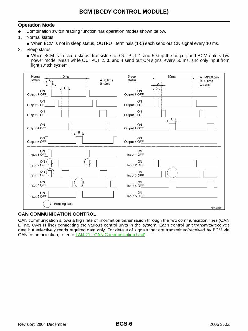
Operation Mode● Combination switch reading function has operation modes shown below.1. Normal status
● When BCM is not in sleep status, OUTPUT terminals (1-5) each send out ON signal every 10 ms.2. Sleep status
● When BCM is in sleep status, transistors of OUTPUT 1 and 5 stop the output, and BCM enters lowpower mode. Mean while OUTPUT 2, 3, and 4 send out ON signal every 60 ms, and only input fromlight switch system.
CAN COMMUNICATION CONTROLCAN communication allows a high rate of information transmission through the two communication lines (CANL line, CAN H line) connecting the various control units in the system. Each control unit transmits/receivesdata but selectively reads required data only. For details of signals that are transmitted/received by BCM viaCAN communication, refer to LAN-21, "CAN Communication Unit" .
PKIB6124E

BCM (BODY CONTROL MODULE)
BCS-7
C
D
E
F
G
H
I
J
L
M
A
B
BCS
Revision: 2004 December 2005 350Z
BCM STATUS CONTROLBCM changes its status depending on the operation status in order to save power consumption.1. CAN communication status
● With ignition switch ON, CAN communicates with other control units normally.● Control by BCM is being operated properly.● When ignition switch is OFF, switching to sleep mode is possible.● Even when ignition switch is OFF, if CAN communication with IPDM E/R and combination meter is
active, CAN communication status is active.2. Sleep transient status
● This status shuts down CAN communication when ignition switch is turned OFF.● It transmits sleep request signal to IPDM E/R and combination meter.● Two seconds after CAN communication of all control units stops, sleep transient status switches to CAN
communication inactive status.3. CAN communication inactive status
● With ignition switch OFF, CAN communication is not active.● With ignition switch OFF, control performed only by BCM is active.● Three seconds after CAN communication of all control units stops, CAN communication inactive status
switches to sleep status.4. Sleep status
● BCM is activated with low power mode.● CAN communication is not active.● When CAN communication operation is detected, it switches to CAN communication status.● When a state of the following switches changes, it switches to CAN communication state.– Key switch– Hazard switch– Door lock/unlock switch– Front door switch (driver side, passenger side)– Back door opener switch– Combination switch (passing, lighting switch 1st position)– Key fob (lock/unlock signal)– Key cylinder switch● When control performed only by BCM is required by switch, it shifts to CAN communication inactive
mode.● Status of combination switch reading function is changed.

BCS-8
BCM (BODY CONTROL MODULE)
Revision: 2004 December 2005 350Z
SYSTEMS CONTROLLED BY BCM DIRECTLY
NOTE:1. Power supply only. No system control.
2. Coupe models
SYSTEMS CONTROLLED BY BCM AND IPDM E/R
SYSTEMS CONTROLLED BY BCM AND COMBINATION METER
System Reference
Power door lock BL-21, "POWER DOOR LOCK SYSTEM"
Remote keyless entry BL-62, "REMOTE KEYLESS ENTRY SYSTEM"
Power window NOTE 1 GW-18, "POWER WINDOW SYSTEM"
Power seat NOTE 1 SE-12, "POWER SEAT/FOR COUPE" or SE-15, "POWER SEAT/FOR ROADSTER"
Room lamp timer LT-214, "INTERIOR ROOM LAMP"
Rear wiper NOTE 2 WW-38, "REAR WIPER AND WASHER SYSTEM"
System Reference
Panic alarm BL-62, "REMOTE KEYLESS ENTRY SYSTEM"
Theft warning BL-134, "VEHICLE SECURITY (THEFT WARNING) SYSTEM"
NVIS (NATS) BL-164, "NVIS (NISSAN VEHICLE IMMOBILIZER SYSTEM-NATS)"
Headlamp, clearance lamp tail lamp, Battery saver control, day time light system
● LT-7, "HEADLAMP (FOR USA) - XENON TYPE -"
● LT-38, "HEADLAMP (FOR USA) - CONVENTIONAL TYPE -"
● LT-67, "HEADLAMP (FOR CANADA) - XENON TYPE -"
● LT-108, "HEADLAMP (FOR CANADA) - CONVENTIONAL TYPE -"
Front wiper WW-4, "FRONT WIPER AND WASHER SYSTEM"
Rear window defogger GW-57, "REAR WINDOW DEFOGGER"
System Reference
Warning chime DI-79, "WARNING CHIME"
Turn signal and hazard warning lamps LT-147, "TURN SIGNAL AND HAZARD WARNING LAMPS"
Low tire pressure warning system WT-10, "LOW TIRE PRESSURE WARNING SYSTEM"

BCM (BODY CONTROL MODULE)
BCS-9
C
D
E
F
G
H
I
J
L
M
A
B
BCS
Revision: 2004 December 2005 350Z
MAJOR COMPONENTS AND CONTROL SYSTEMSystem Input Output
Remote control entry system Remote keyless entry receiver● All-door locking actuator
● Turn signal lamp (LH, RH)
Power door lock system
● Power window main switch (door lock and unlock switch)
● Power window sub switch (passenger side) (door lock and unlock switch)
All-door locking actuator
Power supply (IGN) to power window Ignition power supply Power window system
Power supply (BAT) to power window and power seat
Battery power supplyPower window system and power seat
Panic alarm● Key switch
● Remote keyless entry receiverIPDM E/R
Theft warning system
● All-door switch
● Remote keyless entry receiver
● Power window main switch (door lock and unlock switch)
● IPDM E/R
● Security indicator lamp
Battery saver control● Ignition switch
● Combination switchIPDM E/R
Headlamp Combination switch IPDM E/R
Day time light system
● Engine speed signal
● Ignition switch
● Combination switch
IPDM E/R
Tail lamp Combination switch IPDM E/R
Turn signal lamp Combination switch● Turn signal lamp
● Combination meter
Hazard lamp Hazard switch● Turn signal lamp
● Combination meter
Room lamp timer
● Key switch
● Remote keyless entry receiver
● Power window main switch (door lock and unlock switch)
● Front door switch driver side
● All-door switch
Interior room lamp
Key warning chime● Key switch
● Front door switch driver side
Combination meter(warning buzzer)
Light warning chime
● Combination switch
● Key switch
● Front door switch driver side
Combination meter(warning buzzer)
Seat belt warning chime
● Combination meter [Seat belt buckle (driver side) switch]
● Ignition switch
Combination meter(warning buzzer)
Vehicle-speed-sensing intermittent wiper● Combination switch
● Combination meterIPDM E/R
Rear intermittent wiper NOTE Combination switch Rear wiper motor
Rear window defogger● Rear window defogger switch
● Ignition switchIPDM E/R
A/C switch signal Unified meter and A/C amp. ECM

BCS-10
BCM (BODY CONTROL MODULE)
Revision: 2004 December 2005 350Z
NOTE:Coupe models
CAN Communication System Description AKS000Z4
CAN (Controller Area Network) is a serial communication line for real time application. It is an on-vehicle mul-tiplex communication line with high data communication speed and excellent error detection ability. Modernvehicles are equipped with many electronic control units and each control unit shares information and linkswith other control units during operation (not independent). In CAN communication, control units are con-nected with 2 communication lines (CAN H line, CAN L line) allowing a high rate of information transmissionwith less wiring. Each control unit transmits/receives data but selectively reads required data only.
CAN Communication Unit AKS003MH
Refer to LAN-21, "CAN Communication Unit" .
Blower fan switch signal Unified meter and A/C amp. ECM
Low tire pressure warning system Remote keyless entry receiver Combination meter
System Input Output

BCM (BODY CONTROL MODULE)
BCS-11
C
D
E
F
G
H
I
J
L
M
A
B
BCS
Revision: 2004 December 2005 350Z
Schematic AKS000Z5
COUPE MODELS
TKWT1872E

BCS-12
BCM (BODY CONTROL MODULE)
Revision: 2004 December 2005 350Z
TKWT2340E

BCM (BODY CONTROL MODULE)
BCS-13
C
D
E
F
G
H
I
J
L
M
A
B
BCS
Revision: 2004 December 2005 350Z
ROADSTER MODELS
TKWT1874E

BCS-14
BCM (BODY CONTROL MODULE)
Revision: 2004 December 2005 350Z
TKWT2341E

BCM (BODY CONTROL MODULE)
BCS-15
C
D
E
F
G
H
I
J
L
M
A
B
BCS
Revision: 2004 December 2005 350Z
CONSULT-II Function (BCM) AKS00AV6
CONSULT-II can display each diagnostic item using the diagnostic test mode shown following.
CONSULT–II BASIC OPERATIONCAUTION:If CONSULT-II is used with no connection of CONSULT-II CONVERTER, malfunctions might bedetected in self-diagnosis depending on control unit which carry out CAN communication. 1. With the ignition switch OFF, connect CONSULT-II and CON-
SULT-II CONVERTER to the data link connector, then turn theignition switch ON.
2. Touch “START (NISSAN BASED VHCL)”.
3. Touch “BCM” on “SELECT SYSTEM” screen.If “BCM” is not indicated, go to GI-39, "CONSULT-II Data LinkConnector (DLC) Circuit" .
BCM diagnostic test item Check item, diagnostic test mode Content
Inspection by part
WORK SUPPORT Changes setting of each function.
SELF-DIAG RESULTS BCM performs self-diagnosis of CAN communication.
DATA MONITOR Displays the input data of BCM in real time.
ACTIVE TEST Gives a drive signal to a load to check the operation.
CAN DIAG SUPPORT MNTRThe result of transmit/receive diagnosis of CAN com-munication can be read.
ECU PART NUMBER ECM part number can be read.
PBIB1069E
BCIA0029E
BCIA0030E

BCS-16
BCM (BODY CONTROL MODULE)
Revision: 2004 December 2005 350Z
4. Select the desired part to be diagnosed on the “SELECT TESTITEM” screen.
ITEMS OF EACH PARTNOTE:CONSULT-II displays systems equipped in the vehicle.
×:Applicable
NOTE:This item is displayed, but should not be used.
PKIA6100E
System and item CONSULT-II display
Diagnostic test mode (Inspection by part)
WORK SUPPORT
SELF−DIAG
RESULTS
DATA MONI-TOR
CAN DIAG SUP-PORT MNTR
ACTIVE TEST
ECU PART NUM-BER
CON-FIGU-
RATION
BCM BCM × × × × × NOTE
Power door lock system DOOR LOCK × × ×
Rear window defogger REAR DEFOGGER × ×
Warning chime BUZZER × ×
Room lamp timer INT LAMP × × ×
Remotecontrol entry system MULTI REMOTE ENT × × ×
Headlamp HEAD LAMP × × ×
Wiper WIPER × × ×
Turn signal lampHazard lamp
FLASHER × ×
Blower fan switch signalA/C switch signal
AIR CONDITONER ×
Combination switch COMB SW ×
NVIS IMMU × ×
Room lamp battery saver BATTERY SAVER × × ×
Trunk lid TRUNK × ×
Vehicle security system THEFT ALM × × ×
Retained power control RETAINED PWR × × ×
Oil pressure switch SIGNAL BUFFER × NOTE ×
Fuel lid FUEL LID × ×
Low tire pressure warning system
AIR PRESSURE MONITOR
× × ×
Panic system PANIC ALARM ×

BCM (BODY CONTROL MODULE)
BCS-17
C
D
E
F
G
H
I
J
L
M
A
B
BCS
Revision: 2004 December 2005 350Z
WORK SUPPORTOperation Procedure1. Touch “BCM” on “SELECT TEST ITEM” screen.2. Touch “WORK SUPPORT” on “SELECT DIAG MODE” screen.3. Touch item on “SELECT WORK ITEM” screen.4. Touch “START”.5. Touch “CHANGE SET”.6. The setting will be changed and “RESETTING COMPLETED” will be displayed.7. Touch “END”.
Display Item List
CAN Communication Inspection Using CONSULT-II (Self-Diagnosis) AKS000Z7
1. SELF-DIAGNOSTIC RESULT CHECK
CAUTION:If CONSULT-II is used with no connection of CONSULT-II CONVERTER, malfunctions might bedetected in self-diagnosis depending on control unit which carry out CAN communication. 1. Connect to CONSULT-II, and select “BCM” on “SELECT SYSTEM” screen.2. Select “BCM control unit ” on “SELECT WORK ITEM” screen, and select “SELF-DIAG RESULTS”.3. Check display content in self-diagnostic results.
Contents displayedNo malfunction>>INSPECTION ENDMalfunction in CAN communication system>>After printing the monitor items, go to “CAN System”. Refer to
LAN-3, "Precautions When Using CONSULT-II" .
Item Description
RESET SETTING VALUE Return a value set with WORK SUPPORT of each system to a default value in factory shipment.
CONSULT-II display code Diagnosis item
U1000
INITIAL DIAG
TRANSMIT DIAG
ECM
IPDM E/R
METER / M&A

BCS-18
BCM (BODY CONTROL MODULE)
Revision: 2004 December 2005 350Z
Removal and Installation of BCM AKS000ZB
REMOVAL1. Remove the dash side finisher (LH). Refer to EI-35, "BODY
SIDE TRIM" in “EI Exterior/Interior.”2. Disconnect BCM connector.3. Remove bracket mounting screws (3) to remove BCM and fuse
block with bracket.
4. Raise the pawl of fuse block and remove bracket from fuse blockto remove BCM.
INSTALLATIONInstallation is the reverse order of removal.
SKIA1918E
SKIA1919E