Embed Size (px)
DESCRIPTION
Boiler basic design
Citation preview

Boiler Basics: Design & Application Differences
Presented by Steve Connor July 30, 2014
Design & Construction
Details
The Boiler Package
Industry & Application Match-Up
Types of Fueled Boilers
Understanding Boiler Load
Boiler Manufacturing Requirements
What We Are Covering Today
2
Boiler Basics: Design &
Application Differences
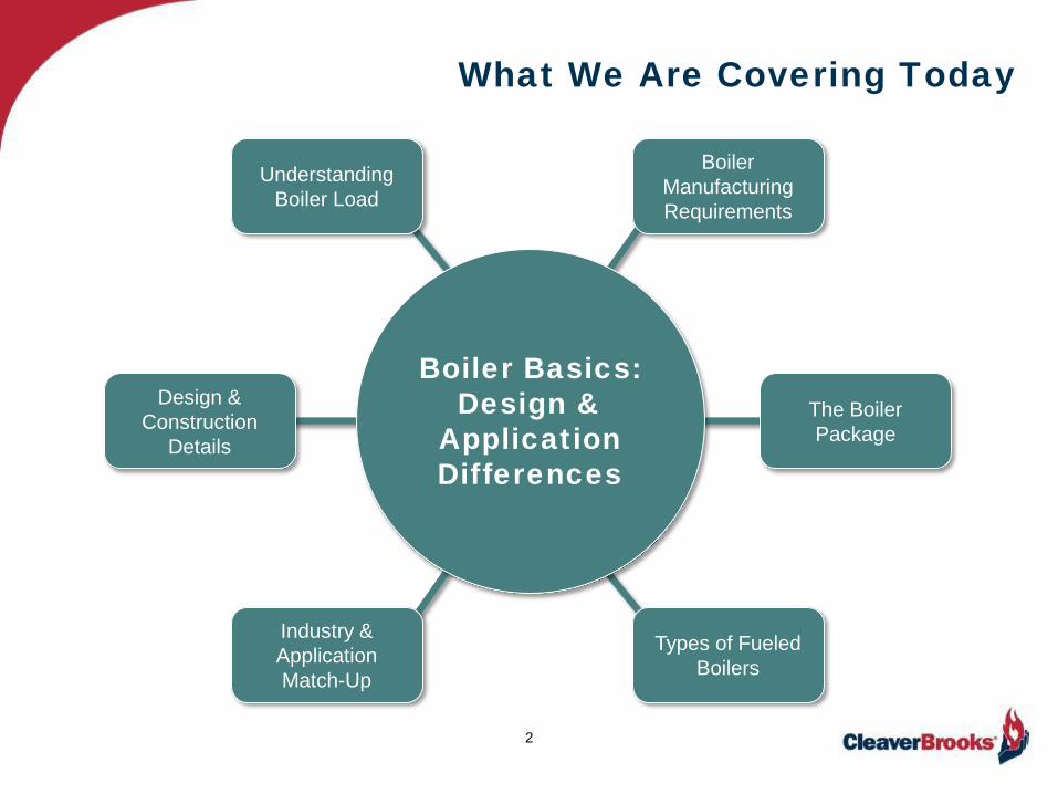
Boiler Manufacturing
3
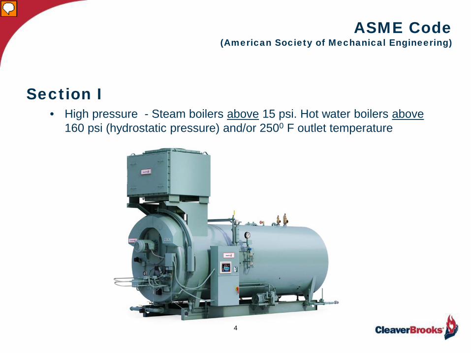
ASME Code (American Society of Mechanical Engineering)
Section I • High pressure - Steam boilers above 15 psi. Hot water boilers above
160 psi (hydrostatic pressure) and/or 2500 F outlet temperature
4

ASME Code (American Society of Mechanical Engineering)
Section IV • Low pressure - Steam boilers less than 15 psi. Hot water boilers less
than 160 psi and/or 2500 F. outlet temperature
5

Packaged Boiler Types
6
General Categories
Firetube Watertube Tubeless Electric
Capacity 200 – 365,000 MBH
6 – 11,000 BHP Steam & Hot Water

The Boiler Package
• Pressure vessel • Burner • Controls
7
Pressure Vessel Burner
Combustion Controls Burner Management
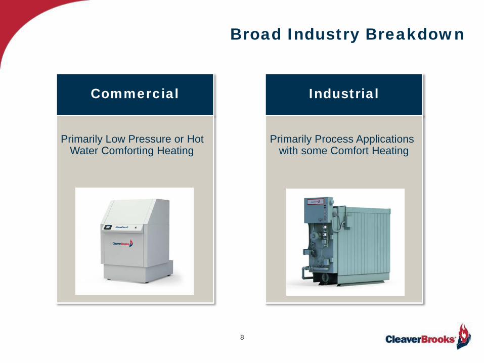
Broad Industry Breakdown
8
Commercial
Primarily Low Pressure or Hot
Water Comforting Heating
Industrial
Primarily Process Applications
with some Comfort Heating

Commercial Steam & Hot Water
• Firetube • Vertical Tubeless • Electric • Watertube • Cast Iron • Copper Fin
9
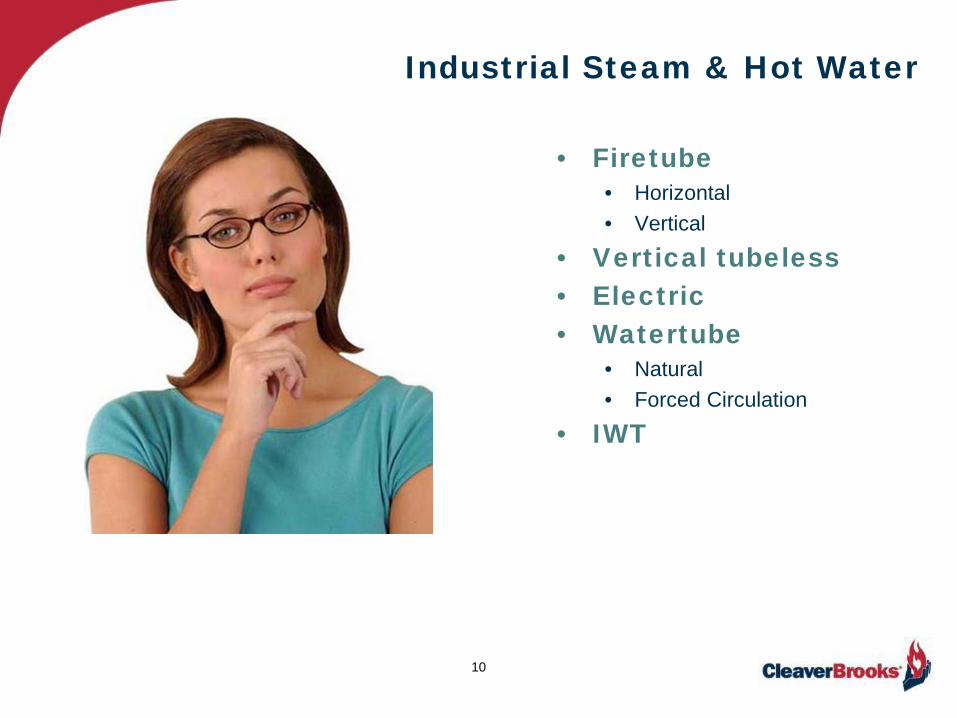
Industrial Steam & Hot Water
• Firetube • Horizontal • Vertical
• Vertical tubeless • Electric • Watertube
• Natural • Forced Circulation
• IWT
10
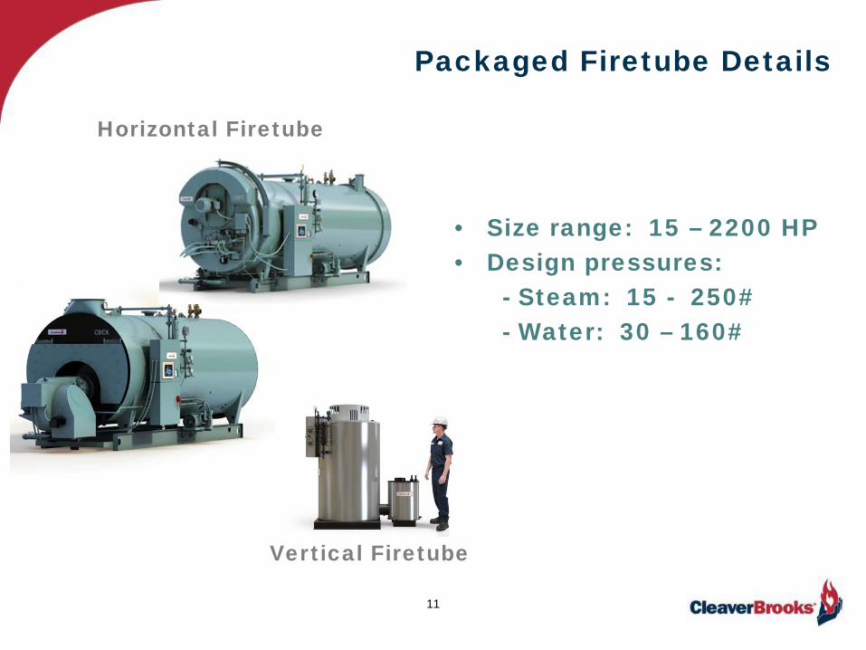
Packaged Firetube Details
• Size range: 15 – 2200 HP • Design pressures: - Steam: 15 - 250# - Water: 30 – 160#
11
Vertical Firetube
Horizontal Firetube

Horizontal Firetube Boilers
12
The Dryback
Refractory Filled Door
1 2
3
4
Baffles
Tubesheet
Two (2) Tubesheets

Three (3)Tubesheets
Water Leg
1 2
3
Horizontal Firetube Boiler
13
The Wetback
• Three Tubesheets
• Difficult access, 2nd pass
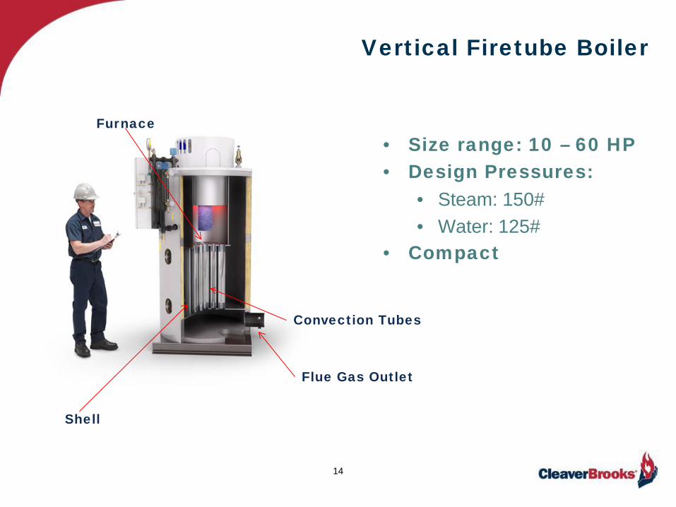
Vertical Firetube Boiler
14
Furnace
Shell
Convection Tubes
Flue Gas Outlet
• Size range: 10 – 60 HP • Design Pressures:
• Steam: 150# • Water: 125#
• Compact

The Watertube Boiler
• Opposite of Firetube • Water in the Tubes • Natural and Forced
Circulation • Large Furnace • Upper & Lower Drums or Headers
15
Upper Drum
Lower Drum
Furnace

The Watertube Boiler
16
Straight Inclined
Bent • Size Range: 15 – 300 HP • Design Pressure: - Steam: 250# - Hot Water: 125#
Down comers
Hx Riser tubes
Sight port
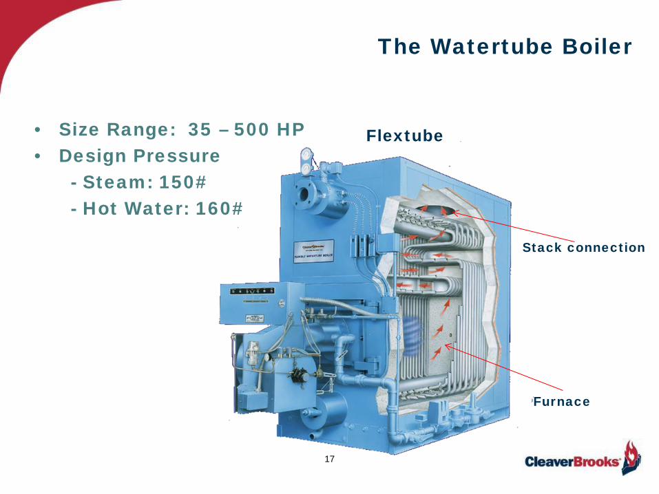
The Watertube Boiler
• Size Range: 35 – 500 HP • Design Pressure - Steam: 150# - Hot Water: 160#
17
Flextube
Furnace
Stack connection
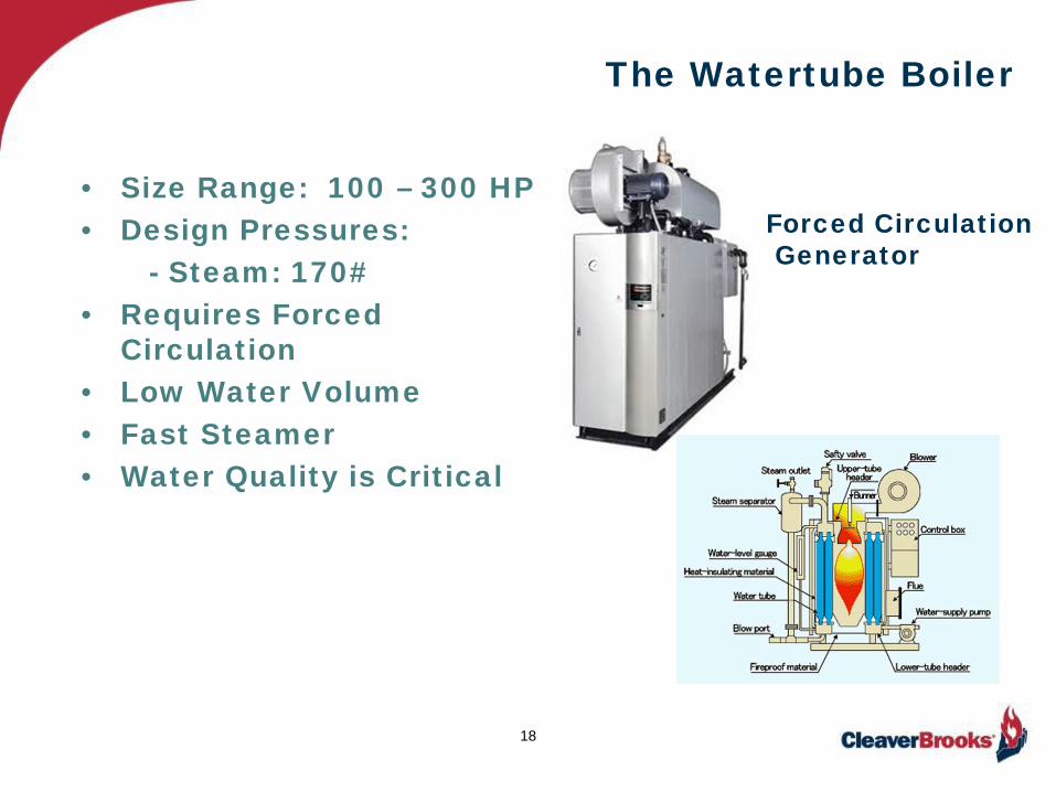
The Watertube Boiler
• Size Range: 100 – 300 HP • Design Pressures: - Steam: 170# • Requires Forced
Circulation • Low Water Volume • Fast Steamer • Water Quality is Critical
18
Forced Circulation Generator
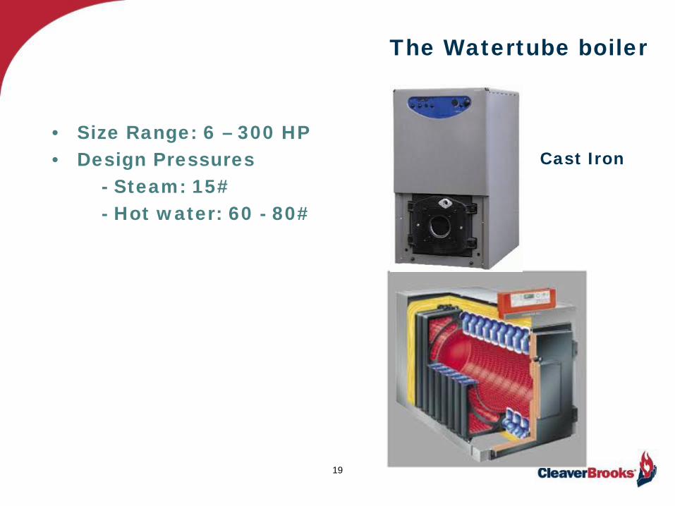
The Watertube boiler
• Size Range: 6 – 300 HP • Design Pressures - Steam: 15# - Hot water: 60 - 80#
19
Cast Iron
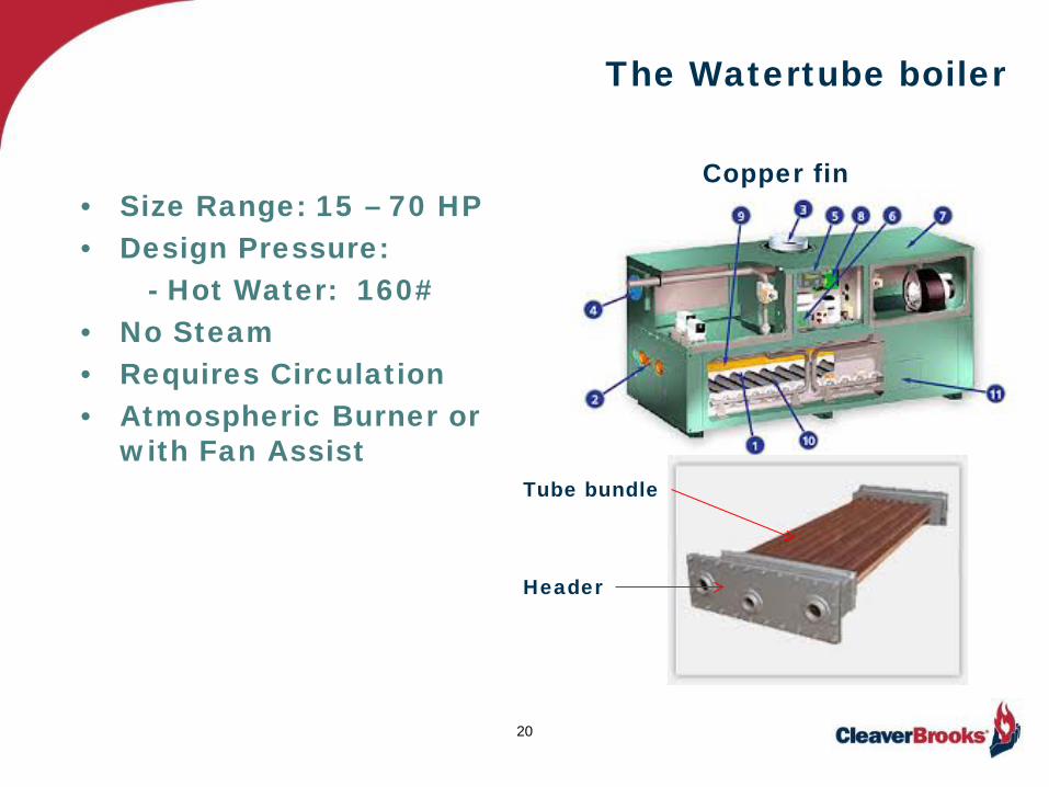
The Watertube boiler
• Size Range: 15 – 70 HP • Design Pressure: - Hot Water: 160# • No Steam • Requires Circulation • Atmospheric Burner or
with Fan Assist
20
Copper fin
Tube bundle
Header

The Watertube boiler package
• Size Range: 10,000 – 300,000#/HR • 300 – 9000 HP • Design Pressure: • Steam: to 900# • HTHW: +400 Deg. F • Natural Circulation • Some Forced Circulation
21
IWT
“A”
“D”
“O”
“A”

Vertical Tubeless boiler
• Size Range: 6 – 100 HP • Design Pressure: - Steam: 150 - 250# - Hot Water: 160# • Multiple Passes (2 – 4)
22
2 Pass Design
Furnace
Convection Zone Transition Zone

Electric Boilers
• Size range: - Resistance: 12 – 3375 KW (1 – 350 BHP)
- Electrode: 2 – 65 MW (200 – 7000 BHP)
• Design Pressure - Steam: To 250# - Hot water (Resistance) 160# • No Emissions on Location • High Point of Use Efficiency
23
Electrode
Resistance
NOTE: MW = 1,000,000 watts KW = 1000 watts or 3413 BTU/HR
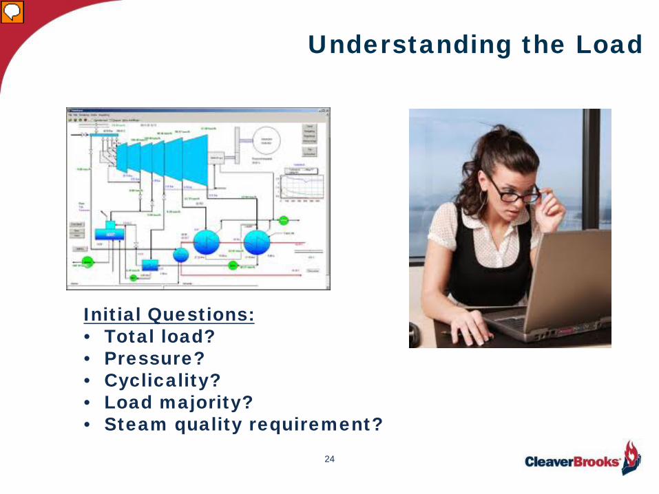
Understanding the Load
24
Initial Questions: • Total load? • Pressure? • Cyclicality? • Load majority? • Steam quality requirement?
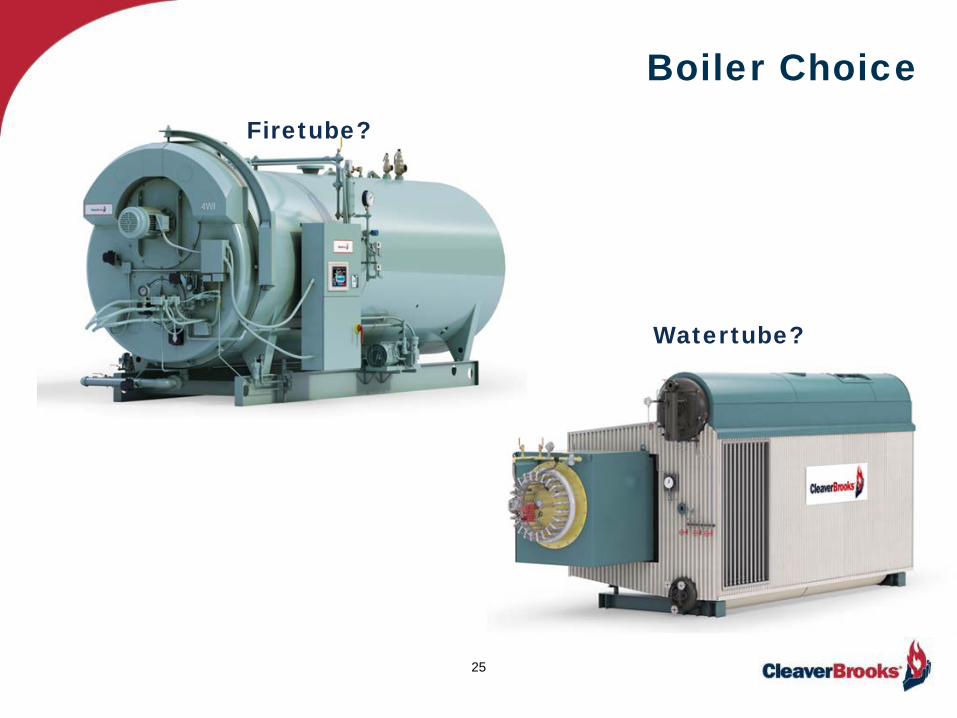
Boiler Choice
25
Firetube?
Watertube?
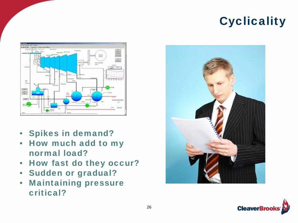
Cyclicality
26
• Spikes in demand? • How much add to my
normal load? • How fast do they occur? • Sudden or gradual? • Maintaining pressure
critical?
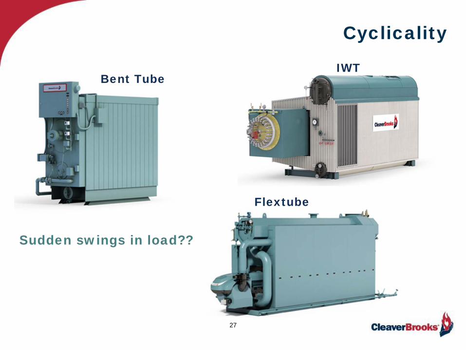
Cyclicality
27
Bent Tube IWT
Flextube
Sudden swings in load??

Burner Choice
Turndown Burner Turndown
Sized for optimum firing rate majority of operating time.
28
Normally 4:1 or 10:1

Purge Losses
ENERGY WA$TE
29
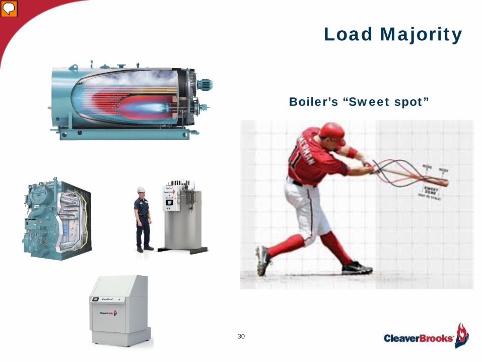
Load Majority
Boiler’s “Sweet spot”
30

Boiler Efficiency & Firing Rate
31
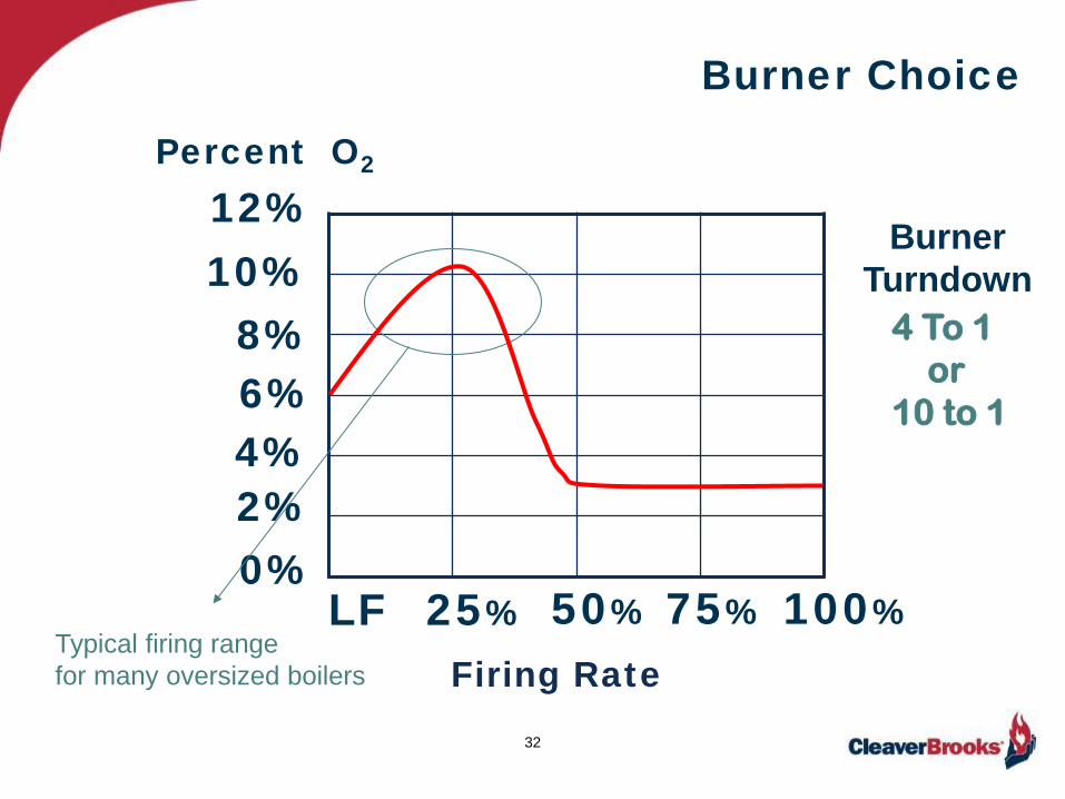
Burner Choice
32
0% 2% 4% 6% 8%
10% 12%
Burner Turndown
4 To 1 or 10 to 1
75% LF 50% 25%
Percent O2
Typical firing range for many oversized boilers
100%
Firing Rate

Burner Choice
33
RULE OF THUMB
For every 2% increase in O2, you lose 1% in efficiency
Reference PDF Available: http://cleaverbrooks.com/Products-and-Solutions/Boilers/Firetube/CBEX-Elite/Excess-Air-and-Boiler-Efficiency.aspx

Combustion Control Choice
34
Single Point Parallel Positioning
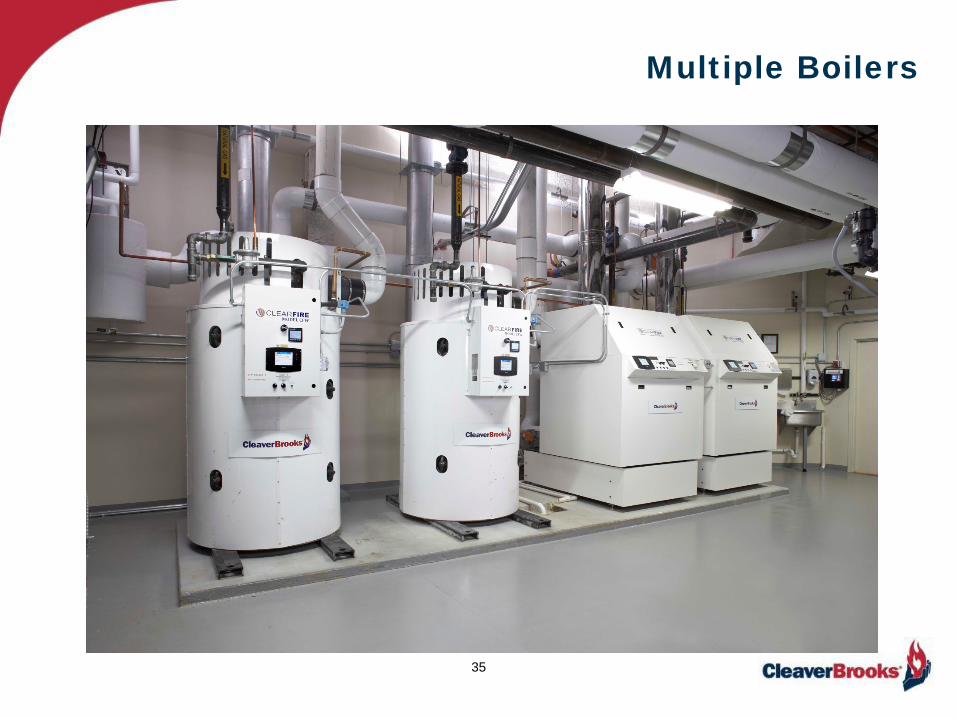
Multiple Boilers
35
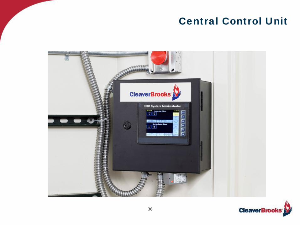
Central Control Unit
36
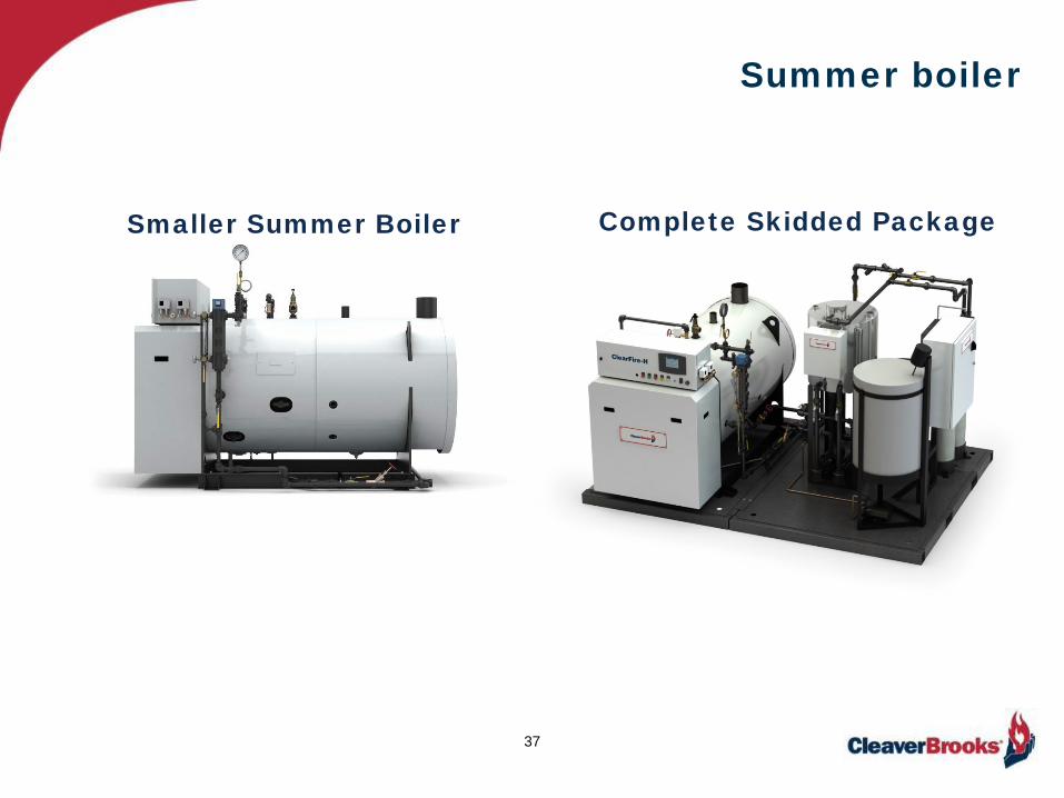
Summer boiler
37
Smaller Summer Boiler Complete Skidded Package
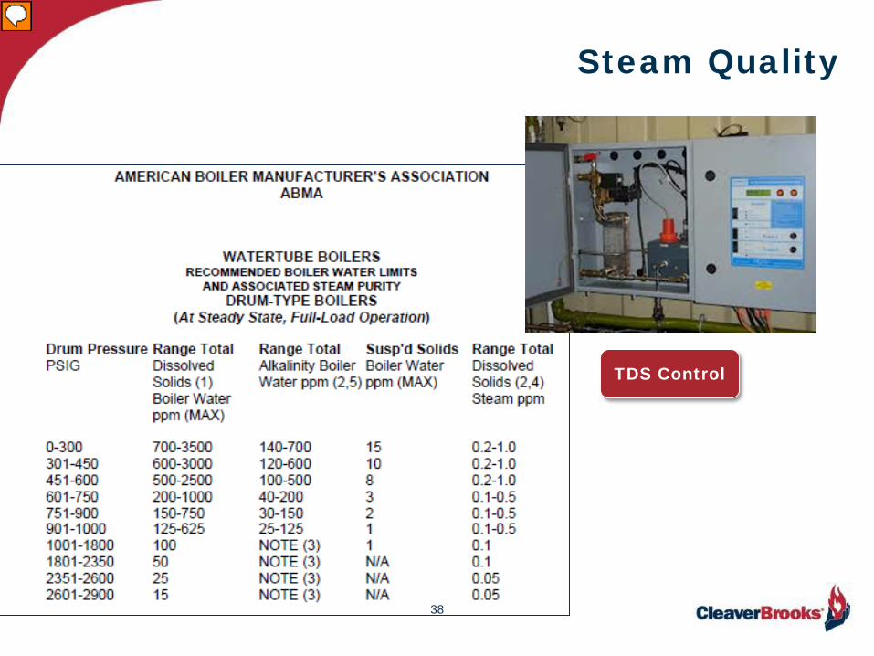
Steam Quality
38
TDS Control
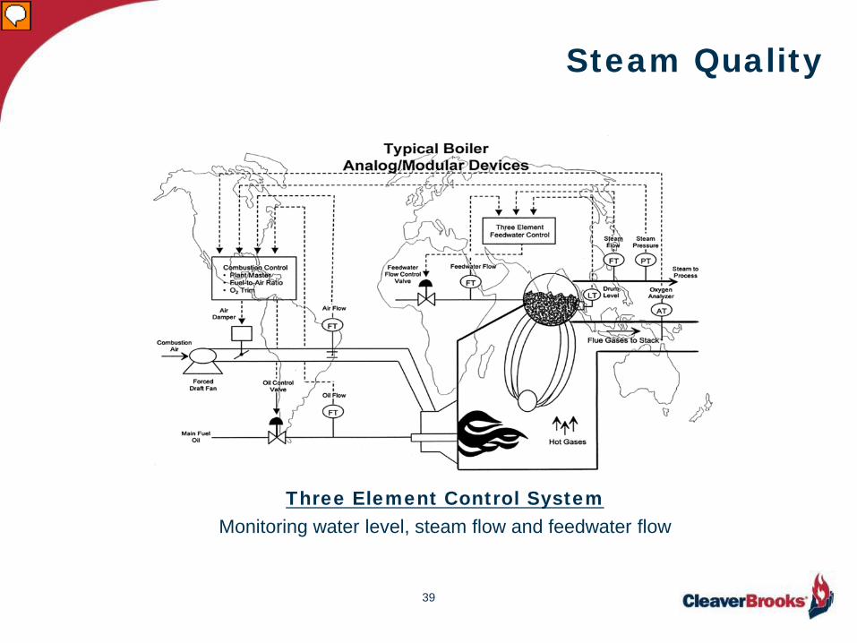
Steam Quality
39
Three Element Control System Monitoring water level, steam flow and feedwater flow
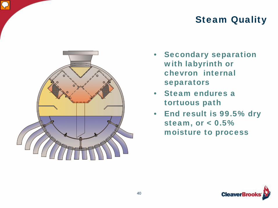
Steam Quality
• Secondary separation with labyrinth or chevron internal separators
• Steam endures a tortuous path
• End result is 99.5% dry steam, or < 0.5% moisture to process
40

Steam Quality
41

Steam Quality
Separator
42
Summary • Boilers constructed per ASME Sections I (HP) & IV (LP & HW) • The boiler package consists of pressure vessel, burner &
controls (BMS & CCS) • Various types of firetubes & watertubes • Firetube package limit @ 2200 HP and 250# • Watertube packages limit at 9000 HP & 900# • The watertube boiler is normally superior in handling “swing”
loads • Cast Iron boilers are LP & HW only • Copper boilers are HW only • When considering the total load, look for cyclicality spikes • Know where the load is the majority of the time assuring the
spikes can be handled within the boilers turndown • Know where the boiler’s “sweet spot” is • Remember 2% increase in O2 = 1% loss in efficiency • Steam quality can be a process issue
43

Contact Us
44