Embed Size (px)
Citation preview
INSTRUCTIONS 910-44754© July 2011, Speedway Motors, Inc.
Bolt-In Mustang II Cross Member for 1947-1954 Chevy 1⁄2 Ton Pickups
PLEASE READ INSTRUCTIONS COMPLETELY BEFORE STARTING YOUR INSTALATION
NOTE: This kit is designed for use with power steering and the full type lower control arms only.
1. Start by supporting the car on four jack stands.
2. Remove all the suspension and steering components from the frame.Leave the front spring shackle mounts that are riveted in the frame. Theyare used for a measuring point for finding your axle centerline.
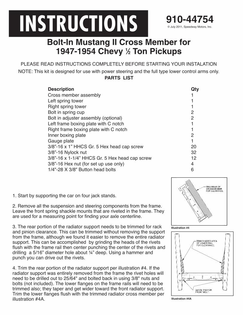
3. The rear portion of the radiator support needs to be trimmed for rackand pinion clearance. This can be trimmed without removing the supportfrom the frame, although we found it easier to remove the entire radiatorsupport. This can be accomplished by grinding the heads of the rivetsflush with the frame rail then center punching the center of the rivets anddrilling a 5/16” diameter hole about ¼” deep. Using a hammer andpunch you can drive out the rivets.
4. Trim the rear portion of the radiator support per illustration #4. If theradiator support was entirely removed from the frame the rivet holes willneed to be drilled out to 25/64" and bolted back in using 3/8" nuts andbolts (not included). The lower flanges on the frame rails will need to betrimmed also; they taper and get wider toward the front radiator support.Trim the lower flanges flush with the trimmed radiator cross member perillustration #4A.
PARTS LIST
Description QtyCross member assembly 1
Left spring tower 1
Right spring tower 1
Bolt in spring cup 2
Bolt in adjuster assembly (optional) 2
Left frame boxing plate with C notch 1
Right frame boxing plate with C notch 1
Inner boxing plate 2
Gauge plate 1
3/8”-16 x 1” HHCS Gr. 5 Hex head cap screw 20
3/8”-16 Nylock nut 32
3/8”-16 x 1-1/4” HHCS Gr. 5 Hex head cap screw 12
3/8”-16 Hex nut (for set up use only) 4
1/4"-28 X 3/8" Button head bolts 6
Illustration #4A
Illustration #4
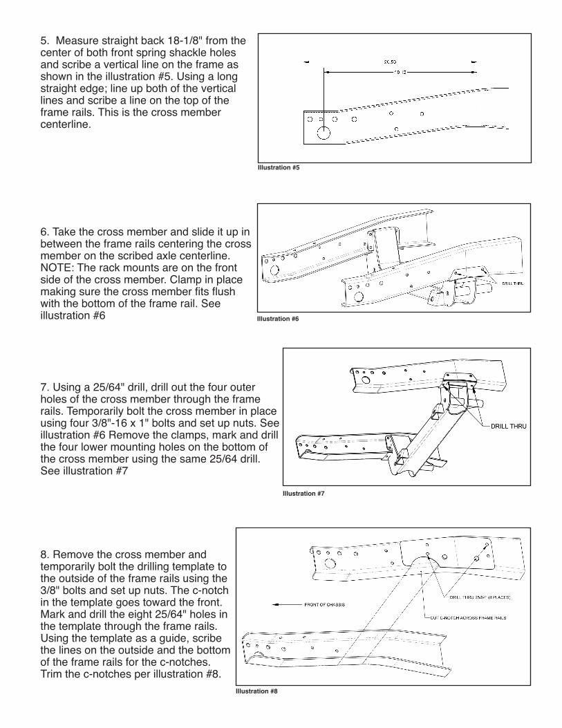
5. Measure straight back 18-1/8" from thecenter of both front spring shackle holesand scribe a vertical line on the frame asshown in the illustration #5. Using a longstraight edge; line up both of the verticallines and scribe a line on the top of theframe rails. This is the cross membercenterline.
6. Take the cross member and slide it up inbetween the frame rails centering the crossmember on the scribed axle centerline.NOTE: The rack mounts are on the frontside of the cross member. Clamp in placemaking sure the cross member fits flushwith the bottom of the frame rail. Seeillustration #6
7. Using a 25/64" drill, drill out the four outerholes of the cross member through the framerails. Temporarily bolt the cross member in placeusing four 3/8"-16 x 1" bolts and set up nuts. Seeillustration #6 Remove the clamps, mark and drillthe four lower mounting holes on the bottom ofthe cross member using the same 25/64 drill.See illustration #7
8. Remove the cross member andtemporarily bolt the drilling template tothe outside of the frame rails using the3/8" bolts and set up nuts. The c-notchin the template goes toward the front.Mark and drill the eight 25/64" holes inthe template through the frame rails.Using the template as a guide, scribethe lines on the outside and the bottomof the frame rails for the c-notches.Trim the c-notches per illustration #8.
Illustration #5
Illustration #6
Illustration #7
Illustration #8
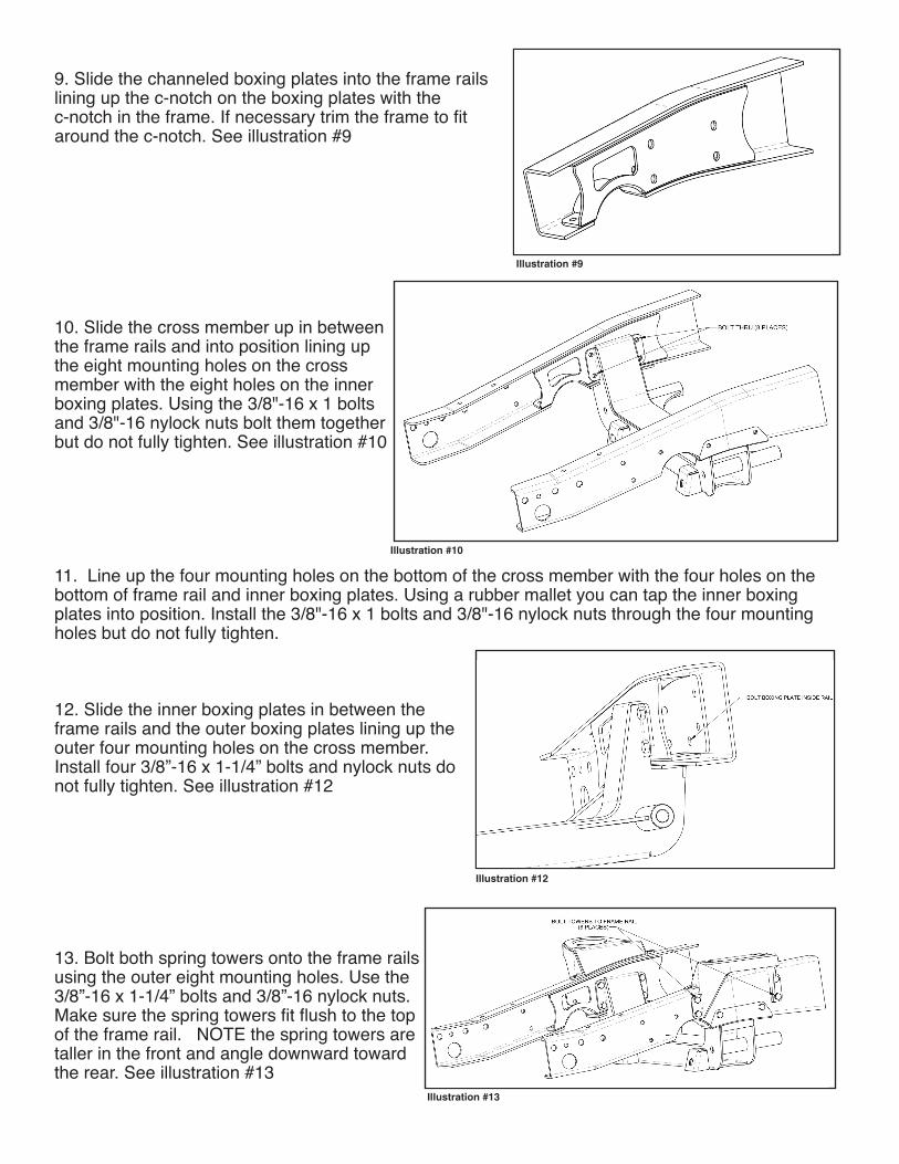
9. Slide the channeled boxing plates into the frame railslining up the c-notch on the boxing plates with the c-notch in the frame. If necessary trim the frame to fitaround the c-notch. See illustration #9
10. Slide the cross member up in betweenthe frame rails and into position lining upthe eight mounting holes on the crossmember with the eight holes on the innerboxing plates. Using the 3/8"-16 x 1 boltsand 3/8"-16 nylock nuts bolt them togetherbut do not fully tighten. See illustration #10
11. Line up the four mounting holes on the bottom of the cross member with the four holes on thebottom of frame rail and inner boxing plates. Using a rubber mallet you can tap the inner boxingplates into position. Install the 3/8"-16 x 1 bolts and 3/8"-16 nylock nuts through the four mountingholes but do not fully tighten.
12. Slide the inner boxing plates in between theframe rails and the outer boxing plates lining up theouter four mounting holes on the cross member.Install four 3/8”-16 x 1-1/4” bolts and nylock nuts donot fully tighten. See illustration #12
13. Bolt both spring towers onto the frame railsusing the outer eight mounting holes. Use the3/8”-16 x 1-1/4” bolts and 3/8”-16 nylock nuts.Make sure the spring towers fit flush to the topof the frame rail. NOTE the spring towers aretaller in the front and angle downward towardthe rear. See illustration #13
Illustration #9
Illustration #10
Illustration #12
Illustration #13
14. Tighten all the 3/8" mounting bolts and nuts to 35 ft. lbs.
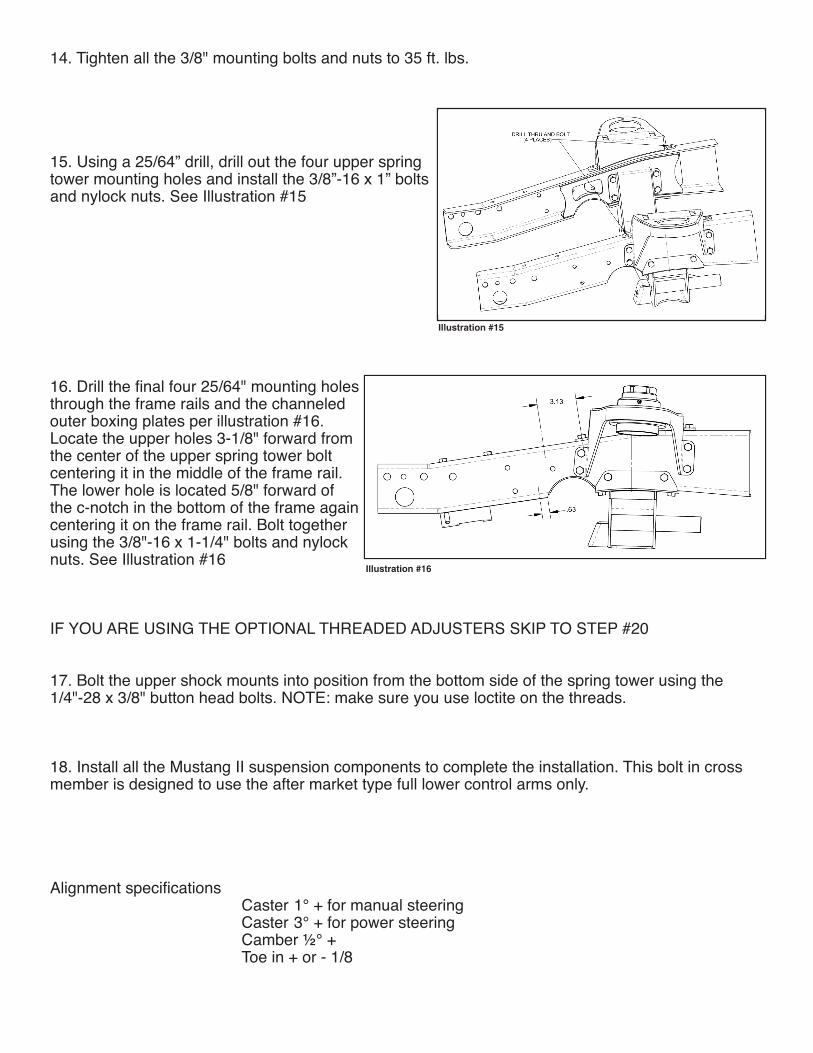
15. Using a 25/64” drill, drill out the four upper springtower mounting holes and install the 3/8”-16 x 1” boltsand nylock nuts. See Illustration #15
16. Drill the final four 25/64" mounting holesthrough the frame rails and the channeledouter boxing plates per illustration #16.Locate the upper holes 3-1/8" forward fromthe center of the upper spring tower boltcentering it in the middle of the frame rail.The lower hole is located 5/8" forward ofthe c-notch in the bottom of the frame againcentering it on the frame rail. Bolt togetherusing the 3/8"-16 x 1-1/4" bolts and nylocknuts. See Illustration #16
IF YOU ARE USING THE OPTIONAL THREADED ADJUSTERS SKIP TO STEP #20
17. Bolt the upper shock mounts into position from the bottom side of the spring tower using the1/4"-28 x 3/8" button head bolts. NOTE: make sure you use loctite on the threads.
18. Install all the Mustang II suspension components to complete the installation. This bolt in crossmember is designed to use the after market type full lower control arms only.
Alignment specifications Caster 1° + for manual steeringCaster 3° + for power steeringCamber ½° +Toe in + or - 1/8
Illustration #15
Illustration #16
IMPO
RTAN
T
DISCLAIMER In an effort to offer our customers the low prices, quickservice and great value, Speedway Motors reserves the right to changesuppliers, specifications, colors, prices, materials. Each of the previousitems is subject to change without notice. Speedway is not responsible forany typographical errors or misinterpretations. Quantities are limited onsome items.
WARRANTY DISCLAIMER The purchaser understands and recognizes thatracing parts, specialized street rod equipment, and all parts and servicessold by Speedway Motors, Inc. are exposed to many and varied conditionsdue to the manner in which they are installed and used. Speedway Motors,Inc. makes no warranties, either express or implied, including any warrantyof merchantability or fitness for a particular purpose other than thosecontained in its current catalog with respect to the goods identified on theface of the invoice. There is no warranty expressed or implied as to whetherthe goods sold hereby will protect purchaser or ultimate user of such goodsfrom injury or death. Speedway Motors assumes no liability after thisperiod.
DAMAGE CLAIMS Always inspect your package upon delivery. Inspect allpackages in the presence of the delivery driver. The driver must note anydamage. Ask the driver the Carrier’s procedures for handling damageclaims. You must hold the original box, packing material and damagedmerchandise for inspection or the carrier will not honor the claim. NotifySpeedway Motors customer service department for instructions onreturning damaged goods. Speedway is not responsible if no notificationis given within 5 days of receipt.
SHORTAGES Always check the contents of your delivery to insure all theparts that you ordered were received. Please read the invoice. Doublecheck all packing materials, small items may be wrapped inside with theseproducts. Shortages may occur from damage to the box, so save allpacking materials. Inspect the box for holes that would allow parts to fallout. If you are missing any item(s) be sure to check your invoice for backorders or canceled items before calling the customer service department.If Speedway has to split a shipment into multiple boxes, packages may bedelivered on different days. You need to contact the customer servicedepartment within 5 days of delivery to assure the prompt replacement.Speedway Motors assumes no liability after this period.
REFUSALS All refused COD customers will be billed a 15% restockingcharge plus freight to and from the destination! If you have questionsplease contact Speedway’s customer service department.
WARRANTY CLAIMS If an item has a manufacturer’s warranty as beingfree from defects we will exchange only. If the item has been used and youare requesting warranty work, this may take up to 30 days as warrantywork is done by the manufacturer NOT Speedway Motors. If you have anyquestions please contact customer service.
RETURNS Speedway wants you to be satisfied with your purchase. Ifwithin 30 days after you receive your shipment you are not satisfied, youmay return the item for refund or exchange. All exchanged or returnedmerchandise must be in original factory conditionwith no modifications oralterations. Returned merchandise must include all packaging materials,warranty cards, manuals, and accessories. If the items being returned needto be repackaged there will be a re-packing charge. Re-pack the item in asturdy box and include a copy of your invoice and complete the form onthe back of the invoice. You must ship orders back PRE-PAID. WE DO NOTACCEPT COD SHIPMENTS.All exchanges need to have reshipping chargesincluded. Items that are returned after 30 days are subject to 15%restocking charges. All fiberglass returned will have 15% restockingcharge. No returns on electrical parts, video tapes, and books. Absolutelyno returns on special order or close out merchandise.
FREE CATALOGSSpeedway Motors offers FREE catalogs for Race, Street,Sprint and Midget, and T-Bucket.
**Some items are not legal for sale or use in California on pollutioncontrolled motor vehicles. These items are legal in California for racingvehicles only which may never be used upon a highway.
© 2011, Speedway Motors, Inc.
Speedway Motors Inc., P.O. Box 81906 Lincoln, NE 68501 402.323.3200 SpeedwayMotors.com
OPTIONAL THREADED ADJUSTERS
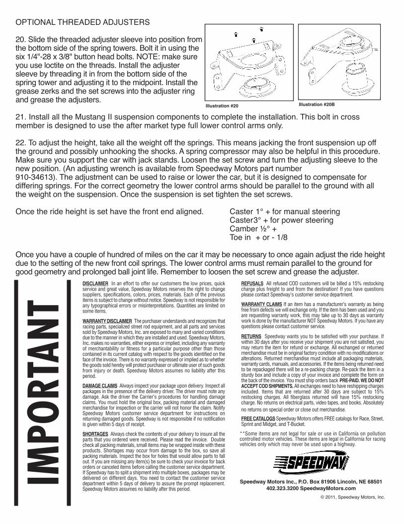
20. Slide the threaded adjuster sleeve into position fromthe bottom side of the spring towers. Bolt it in using thesix 1/4"-28 x 3/8" button head bolts. NOTE: make sureyou use loctite on the threads. Install the adjustersleeve by threading it in from the bottom side of thespring tower and adjusting it to the midpoint. Install thegrease zerks and the set screws into the adjuster ringand grease the adjusters.
21. Install all the Mustang II suspension components to complete the installation. This bolt in crossmember is designed to use the after market type full lower control arms only.
22. To adjust the height, take all the weight off the springs. This means jacking the front suspension up offthe ground and possibly unhooking the shocks. A spring compressor may also be helpful in this procedure.Make sure you support the car with jack stands. Loosen the set screw and turn the adjusting sleeve to thenew position. (An adjusting wrench is available from Speedway Motors part number 910-34613). The adjustment can be used to raise or lower the car, but it is designed to compensate fordiffering springs. For the correct geometry the lower control arms should be parallel to the ground with allthe weight on the suspension. Once the suspension is set tighten the set screws.
Once the ride height is set have the front end aligned. Caster 1° + for manual steeringCaster3° + for power steeringCamber ½° +Toe in + or - 1/8
Once you have a couple of hundred of miles on the car it may be necessary to once again adjust the ride heightdue to the setting of the new front coil springs. The lower control arms must remain parallel to the ground forgood geometry and prolonged ball joint life. Remember to loosen the set screw and grease the adjuster.
Illustration #20 Illustration #20B