Embed Size (px)
Citation preview
Booster regulator/Series VBA Air tank/Series VBAT
Booster Regulator/Air Tank
0.3 MPa
0.3 MPa
0.3 MPa
0.3 MPa
0.6 MPa
Booster Regulator + Air Tank
Heavy
Light
Light
Compressor
Factory line
Series VBA/VBAT
Easy installation
Low heat generation Air-only operation
New product added to the VBA10A series!
Very little heat is generated because no electricity is used, and there is no impact on cylinders, solenoid valves, etc.
Operation is safe because no electricity is used.
Simply insert the unit in the air line. Requires far less space than upgrading the compressor.
There is no need to install dedicated electrical wiring.
NewNew
NEW
Increase factory air pressure by up to twice as much!Air-only operation requires no power supply, reduces heat generation, and allows easy installation.
Increase factory air pressure by up to twice as much!Air-only operation requires no power supply, reduces heat generation, and allows easy installation.
CAT.EUS11-96C-UK
Boost pressure
No power supply or wiring needed
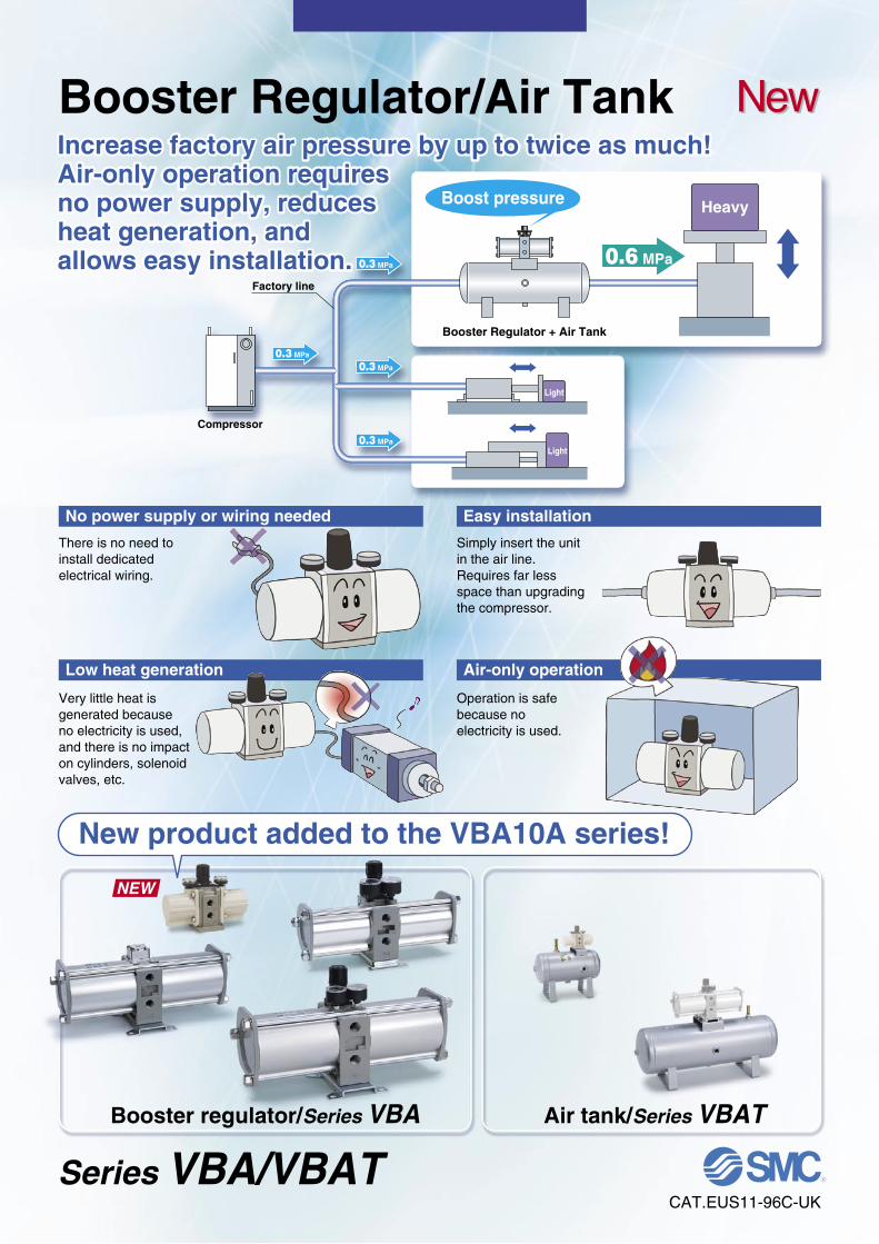
• Floating piston structure (PAT. PEND)• Grease retaining groove∗ Except for VBA1111.
• Prevents operation failure due to foreign matter.∗ Except for VBA1111.
Built-in mesh filter∗ at the IN port
Cylinder tube
Tie-rod guide
Air-feeding tube
VBA22A
VBA42A
Air-operated type
VBA43A
Max. operating pressure 1.6 MPa Fourfold pressureincrease type
Booster Regulator Series VBA
Improvedservice life that of conventional model
Doubledthat of conventional modelDoubled∗
• Metal noise reduced by a damper on the impact partof the switch valve
• Exhaust noise reduced by a high-noise reduction silencer
∗ Except for VBA1111.
Reducednoise
that of conventional model
DoubledReduced by 13 dB (A)compared with the conventional modelReduced by 13 dB (A)compared with the conventional model
Improved reliability
• Mitigates the condensation caused by coolingduring exhaust expansion.
Integrated air-feeding tube with the main tube
Anti-condensation
1/8" gauge portsAllows the use of standard fittings for remote pressure monitoring and the like.∗ Gauge ports changed from 1/16" to 1/8". VBA10A
VBA1111
VBA40A
VBA20A
NEW
Grease retaining groove
Floating structure
Switching valve
Damper
Mesh filter
Gauge port
Features 1
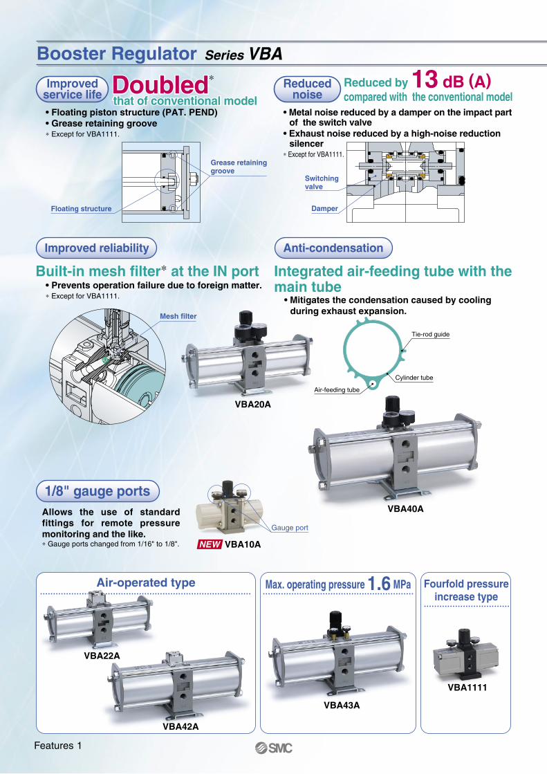
Operation
Body size
Set pressurerange
Handle-operated type (Direct operation)
0.2 to 1.0 MPa0.2 to 1.6 MPa
(2.0 MPa)0.2 to 2.0 MPa
VBA10A VBA1111
VBA20A-03 VBA22A-03
VBA42A-04VBA43A-04VBA40A-04
1/4"
3/8"
1/2"
Air-operated type (Remote operation)
0.2 to 1.0 MPa
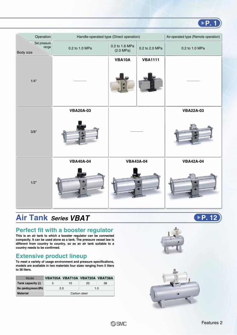
Tank capacity (l)
Max. operating pressure (MPa)
Material
Model VBAT10A10
VBAT20A20
Carbon steel
VBAT38A38
1.02.0
VBAT05A5
P. 1
Air Tank Series VBAT P. 12
Perfect fit with a booster regulatorThis is an air tank to which a booster regulator can be connected compactly. It can be used alone as a tank. The pressure vessel law is different from country to country, so as an air tank suitable to a country needs to be confirmed.
Extensive product lineupTo meet a variety of usage environment and pressure specifications, models are available in two materials four sizes ranging from 5 liters to 38 liters.
Features 2
VBA 02 GN111 11/4
Body size111
4 times
Pressure increase ratio1
Port size
02 1/4Port sizeSymbol
Thread type
RcG
NPTNPTF
Thread type Note)
Symbol
—FNT
Series VBA1111
OptionNonePressure gaugeSilencerPressure gauge, Silencer
OptionSymbol
—GN
GN
VBA 04 GN40A
Port size
020304
1/43/81/2
Port size
VBA10AVBA2AVBA4A
Applicable seriesSymbol
Thread type
RcG
NPTNPTF
Thread type Note)
Symbol
—FNT
Series VBA
OptionNonePressure gaugeSilencerHigh-noise reduction silencer Note)
Pressure gauge, SilencerPressure gauge, High-noise reduction silencer Note)
OptionSymbol
—GNS
GNGS
VBA1111-02
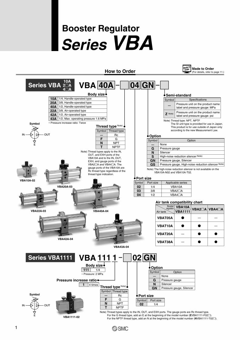
1/4, Handle-operated type3/8, Handle-operated type1/2, Handle-operated type3/8, Air-operated type1/2, Air-operated type1/2, Max. operating pressure 1.6 MPa
Body size10A20A40A22A42A43A
∗ Pressure increase ratio: Twice
∗ Pressure: 2 MPa
Note) Thread type: NPT, NPTFThe SI unit type is provided for use in Japan.This product is for use outside of Japan only according to the new Measurement Law.
Specifications
Pressure unit on the product namelabel and pressure gauge: psi
Pressure unit on the product namelabel and pressure gauge: MPa
Semi-standardSymbol
—
Z Note)
Note) Thread types apply to the IN, OUT, and EXH ports. The gauge ports are Rc thread type. For the G thread type, add an E at the beginning of the model number (EVBA1111-F02). For the NPTF thread type, add an N at the beginning of the model number (NVBA1111-T02).
Symbol
Symbol
Note) Thread types apply to the IN, OUT, and EXH ports of the VBA10A and to the IN, OUT, EXH, and gauge ports of the VBA2A and VBA4A. The gauge ports of the VBA10A are Rc thread type regardless of the thread type indication.
Note) The high-noise reduction silencer is not available on the VBA10A-N02 and VBA10A-T02.
1 4
VBA20A-03
VBA10A-02
VBA40A-04VBA22A-03
VBA42A-04
VBA43A-04
10A2A4A
Made to Order(For details, refer to page 11.)
VBAT05A
VBAT10A
VBAT20A
VBAT38A
VBA10AVBA1111
VBA2A VBA4A
—
—
—
—
—
Air tank compatibility chartBooster
regulator
Air tank
Booster Regulator
Series VBAHow to Order
Related Products/Part No.
Note) Refer to page 12 for air tanks, Best Pneumatics No. 5 for mist separators and Best Pneumatics No. 6 for exhaust cleaners.Refer to the separate instruction manual for the connection method.
Description
Model
Mist separatorExhaust cleaner
For VBA10A-02For VBA1111-02
For VBA20A-03For VBA22A-03
AM250C-02AMC310-03
AM450C-04, 06AMC510-06
AM550C-06, 10AMC610-10
For VBA40A-04For VBA42A-04For VBA43A-04
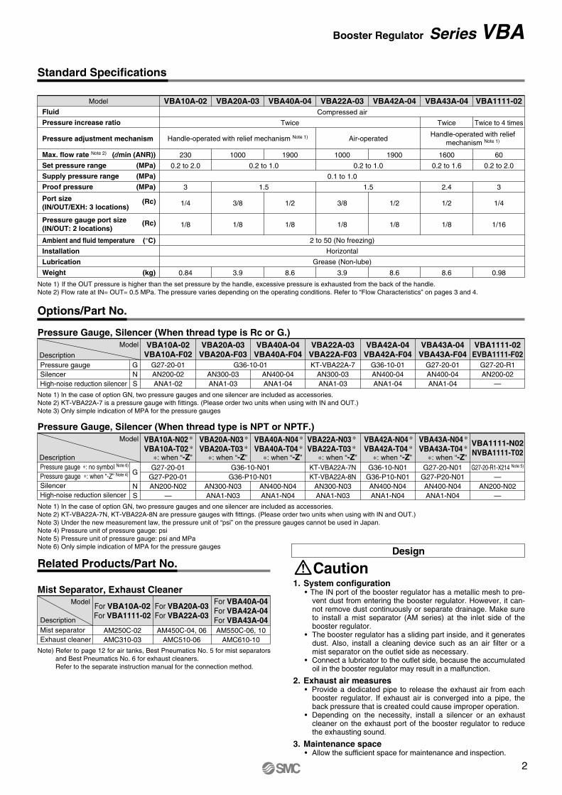
Note 1) If the OUT pressure is higher than the set pressure by the handle, excessive pressure is exhausted from the back of the handle.Note 2) Flow rate at IN= OUT= 0.5 MPa. The pressure varies depending on the operating conditions. Refer to “Flow Characteristics” on pages 3 and 4.
Model
Fluid
Pressure increase ratio
Pressure adjustment mechanism
Max. flow rate Note 2) (l/min (ANR))
Set pressure range (MPa)
Supply pressure range (MPa)
Proof pressure (MPa)
Ambient and fluid temperature (°C)
Installation
Lubrication
Weight (kg)
Port size(IN/OUT/EXH: 3 locations)
Pressure gauge port size(IN/OUT: 2 locations)
VBA10A-02 VBA20A-03 VBA40A-04 VBA22A-03 VBA42A-04 VBA1111-02VBA43A-04Compressed air
0.1 to 1.0
2 to 50 (No freezing)
Horizontal
Grease (Non-lube)
Twice
230
0.2 to 2.0
3
1/4
1/8
0.84
1000
0.2 to 1.0
1.5 1.5
0.2 to 1.0
1900 1000 1900 60
0.2 to 2.0
1600
0.2 to 1.6
Twice to 4 times
Handle-operated with reliefmechanism Note 1)Handle-operated with relief mechanism Note 1) Air-operated
Twice
3/8
1/8
3.9
1/2
1/8
3/8
1/8
1/2
1/8
8.6 3.9 8.6
3
1/4
1/16
0.98
2.4
1/2
1/8
8.6
Note 1) In the case of option GN, two pressure gauges and one silencer are included as accessories.Note 2) KT-VBA22A-7 is a pressure gauge with fittings. (Please order two units when using with IN and OUT.)Note 3) Only simple indication of MPA for the pressure gauges
Pressure Gauge, Silencer (When thread type is Rc or G.)Model
DescriptionPressure gaugeSilencerHigh-noise reduction silencer
GNS
VBA43A-04VBA43A-F04
VBA1111-02EVBA1111-F02
VBA42A-04VBA42A-F04
VBA22A-03VBA22A-F03
VBA40A-04VBA40A-F04
VBA20A-03VBA20A-F03
VBA10A-02VBA10A-F02
G27-20-01AN200-02ANA1-02
G36-10-01AN300-03ANA1-03
AN400-04ANA1-04
KT-VBA22A-7AN300-03ANA1-03
G36-10-01AN400-04ANA1-04
G27-20-R1AN200-02
—
G27-20-01AN400-04ANA1-04
Note 1) In the case of option GN, two pressure gauges and one silencer are included as accessories.Note 2) KT-VBA22A-7N, KT-VBA22A-8N are pressure gauges with fittings. (Please order two units when using with IN and OUT.)Note 3) Under the new measurement law, the pressure unit of “psi” on the pressure gauges cannot be used in Japan.Note 4) Pressure unit of pressure gauge: psiNote 5) Pressure unit of pressure gauge: psi and MPaNote 6) Only simple indication of MPA for the pressure gauges
Pressure Gauge, Silencer (When thread type is NPT or NPTF.)Model
DescriptionPressure gauge ∗: no symbol Note 6)
Pressure gauge ∗: when “-Z” Note 4)
SilencerHigh-noise reduction silencer
G
NS
VBA10A-N02 ∗VBA10A-T02 ∗
∗: when “-Z”
VBA20A-N03 ∗VBA20A-T03 ∗
∗: when “-Z”
VBA40A-N04 ∗VBA40A-T04 ∗
∗: when “-Z”
VBA22A-N03 ∗VBA22A-T03 ∗
∗: when “-Z”
VBA42A-N04 ∗VBA42A-T04 ∗
∗: when “-Z”
VBA1111-N02NVBA1111-T02
VBA43A-N04 ∗VBA43A-T04 ∗
∗: when “-Z”G27-20-01
G27-P20-01AN200-N02
—
G36-10-N01G36-P10-N01
AN300-N03ANA1-N03
AN400-N04ANA1-N04
KT-VBA22A-7NKT-VBA22A-8N
AN300-N03ANA1-N03
G36-10-N01G36-P10-N01AN400-N04ANA1-N04
G27-20-R1-X214 Note 5)
—AN200-N02
—
G27-20-N01G27-P20-N01AN400-N04ANA1-N04
Mist Separator, Exhaust Cleaner
Standard Specifications
(Rc)
(Rc)
Options/Part No.
1. System configuration• The IN port of the booster regulator has a metallic mesh to pre-
vent dust from entering the booster regulator. However, it can-not remove dust continuously or separate drainage. Make sure to install a mist separator (AM series) at the inlet side of the booster regulator.
• The booster regulator has a sliding part inside, and it generates dust. Also, install a cleaning device such as an air filter or a mist separator on the outlet side as necessary.
• Connect a lubricator to the outlet side, because the accumulated oil in the booster regulator may result in a malfunction.
2. Exhaust air measures• Provide a dedicated pipe to release the exhaust air from each
booster regulator. If exhaust air is converged into a pipe, the back pressure that is created could cause improper operation.
• Depending on the necessity, install a silencer or an exhaust cleaner on the exhaust port of the booster regulator to reduce the exhausting sound.
3. Maintenance space• Allow the sufficient space for maintenance and inspection.
CautionDesign
Booster Regulator Series VBA
1
VBA 02 GN111 11/4
Body size111
4 times
Pressure increase ratio1
Port size
02 1/4Port sizeSymbol
Thread type
RcG
NPTNPTF
Thread type Note)
Symbol
—FNT
Series VBA1111
OptionNonePressure gaugeSilencerPressure gauge, Silencer
OptionSymbol
—GN
GN
VBA 04 GN40A
Port size
020304
1/43/81/2
Port size
VBA10AVBA2AVBA4A
Applicable seriesSymbol
Thread type
RcG
NPTNPTF
Thread type Note)
Symbol
—FNT
Series VBA
OptionNonePressure gaugeSilencerHigh-noise reduction silencer Note)
Pressure gauge, SilencerPressure gauge, High-noise reduction silencer Note)
OptionSymbol
—GNS
GNGS
VBA1111-02
1/4, Handle-operated type3/8, Handle-operated type1/2, Handle-operated type3/8, Air-operated type1/2, Air-operated type1/2, Max. operating pressure 1.6 MPa
Body size10A20A40A22A42A43A
∗ Pressure increase ratio: Twice
∗ Pressure: 2 MPa
Note) Thread type: NPT, NPTFThe SI unit type is provided for use in Japan.This product is for use outside of Japan only according to the new Measurement Law.
Specifications
Pressure unit on the product namelabel and pressure gauge: psi
Pressure unit on the product namelabel and pressure gauge: MPa
Semi-standardSymbol
—
Z Note)
Note) Thread types apply to the IN, OUT, and EXH ports. The gauge ports are Rc thread type. For the G thread type, add an E at the beginning of the model number (EVBA1111-F02). For the NPTF thread type, add an N at the beginning of the model number (NVBA1111-T02).
Symbol
Symbol
Note) Thread types apply to the IN, OUT, and EXH ports of the VBA10A and to the IN, OUT, EXH, and gauge ports of the VBA2A and VBA4A. The gauge ports of the VBA10A are Rc thread type regardless of the thread type indication.
Note) The high-noise reduction silencer is not available on the VBA10A-N02 and VBA10A-T02.
1 4
VBA20A-03
VBA10A-02
VBA40A-04VBA22A-03
VBA42A-04
VBA43A-04
10A2A4A
Made to Order(For details, refer to page 11.)
VBAT05A
VBAT10A
VBAT20A
VBAT38A
VBA10AVBA1111
VBA2A VBA4A
—
—
—
—
—
Air tank compatibility chartBooster
regulator
Air tank
Booster Regulator
Series VBAHow to Order
Related Products/Part No.
Note) Refer to page 12 for air tanks, Best Pneumatics No. 5 for mist separators and Best Pneumatics No. 6 for exhaust cleaners.Refer to the separate instruction manual for the connection method.
Description
Model
Mist separatorExhaust cleaner
For VBA10A-02For VBA1111-02
For VBA20A-03For VBA22A-03
AM250C-02AMC310-03
AM450C-04, 06AMC510-06
AM550C-06, 10AMC610-10
For VBA40A-04For VBA42A-04For VBA43A-04
Note 1) If the OUT pressure is higher than the set pressure by the handle, excessive pressure is exhausted from the back of the handle.Note 2) Flow rate at IN= OUT= 0.5 MPa. The pressure varies depending on the operating conditions. Refer to “Flow Characteristics” on pages 3 and 4.
Model
Fluid
Pressure increase ratio
Pressure adjustment mechanism
Max. flow rate Note 2) (l/min (ANR))
Set pressure range (MPa)
Supply pressure range (MPa)
Proof pressure (MPa)
Ambient and fluid temperature (°C)
Installation
Lubrication
Weight (kg)
Port size(IN/OUT/EXH: 3 locations)
Pressure gauge port size(IN/OUT: 2 locations)
VBA10A-02 VBA20A-03 VBA40A-04 VBA22A-03 VBA42A-04 VBA1111-02VBA43A-04Compressed air
0.1 to 1.0
2 to 50 (No freezing)
Horizontal
Grease (Non-lube)
Twice
230
0.2 to 2.0
3
1/4
1/8
0.84
1000
0.2 to 1.0
1.5 1.5
0.2 to 1.0
1900 1000 1900 60
0.2 to 2.0
1600
0.2 to 1.6
Twice to 4 times
Handle-operated with reliefmechanism Note 1)Handle-operated with relief mechanism Note 1) Air-operated
Twice
3/8
1/8
3.9
1/2
1/8
3/8
1/8
1/2
1/8
8.6 3.9 8.6
3
1/4
1/16
0.98
2.4
1/2
1/8
8.6
Note 1) In the case of option GN, two pressure gauges and one silencer are included as accessories.Note 2) KT-VBA22A-7 is a pressure gauge with fittings. (Please order two units when using with IN and OUT.)Note 3) Only simple indication of MPA for the pressure gauges
Pressure Gauge, Silencer (When thread type is Rc or G.)Model
DescriptionPressure gaugeSilencerHigh-noise reduction silencer
GNS
VBA43A-04VBA43A-F04
VBA1111-02EVBA1111-F02
VBA42A-04VBA42A-F04
VBA22A-03VBA22A-F03
VBA40A-04VBA40A-F04
VBA20A-03VBA20A-F03
VBA10A-02VBA10A-F02
G27-20-01AN200-02ANA1-02
G36-10-01AN300-03ANA1-03
AN400-04ANA1-04
KT-VBA22A-7AN300-03ANA1-03
G36-10-01AN400-04ANA1-04
G27-20-R1AN200-02
—
G27-20-01AN400-04ANA1-04
Note 1) In the case of option GN, two pressure gauges and one silencer are included as accessories.Note 2) KT-VBA22A-7N, KT-VBA22A-8N are pressure gauges with fittings. (Please order two units when using with IN and OUT.)Note 3) Under the new measurement law, the pressure unit of “psi” on the pressure gauges cannot be used in Japan.Note 4) Pressure unit of pressure gauge: psiNote 5) Pressure unit of pressure gauge: psi and MPaNote 6) Only simple indication of MPA for the pressure gauges
Pressure Gauge, Silencer (When thread type is NPT or NPTF.)Model
DescriptionPressure gauge ∗: no symbol Note 6)
Pressure gauge ∗: when “-Z” Note 4)
SilencerHigh-noise reduction silencer
G
NS
VBA10A-N02 ∗VBA10A-T02 ∗
∗: when “-Z”
VBA20A-N03 ∗VBA20A-T03 ∗
∗: when “-Z”
VBA40A-N04 ∗VBA40A-T04 ∗
∗: when “-Z”
VBA22A-N03 ∗VBA22A-T03 ∗
∗: when “-Z”
VBA42A-N04 ∗VBA42A-T04 ∗
∗: when “-Z”
VBA1111-N02NVBA1111-T02
VBA43A-N04 ∗VBA43A-T04 ∗
∗: when “-Z”G27-20-01
G27-P20-01AN200-N02
—
G36-10-N01G36-P10-N01
AN300-N03ANA1-N03
AN400-N04ANA1-N04
KT-VBA22A-7NKT-VBA22A-8N
AN300-N03ANA1-N03
G36-10-N01G36-P10-N01AN400-N04ANA1-N04
G27-20-R1-X214 Note 5)
—AN200-N02
—
G27-20-N01G27-P20-N01AN400-N04ANA1-N04
Mist Separator, Exhaust Cleaner
Standard Specifications
(Rc)
(Rc)
Options/Part No.
1. System configuration• The IN port of the booster regulator has a metallic mesh to pre-
vent dust from entering the booster regulator. However, it can-not remove dust continuously or separate drainage. Make sure to install a mist separator (AM series) at the inlet side of the booster regulator.
• The booster regulator has a sliding part inside, and it generates dust. Also, install a cleaning device such as an air filter or a mist separator on the outlet side as necessary.
• Connect a lubricator to the outlet side, because the accumulated oil in the booster regulator may result in a malfunction.
2. Exhaust air measures• Provide a dedicated pipe to release the exhaust air from each
booster regulator. If exhaust air is converged into a pipe, the back pressure that is created could cause improper operation.
• Depending on the necessity, install a silencer or an exhaust cleaner on the exhaust port of the booster regulator to reduce the exhausting sound.
3. Maintenance space• Allow the sufficient space for maintenance and inspection.
CautionDesign
Booster Regulator Series VBA
2
12
11
10
9
8
7
6
5
4
3
2
10
Cha
rge
time
per
10 li
ters
t (
s)
1.0 1.1 1.2 1.3 1.4 1.5 1.6 1.7 1.8 1.9 2.0
Pressure increase ratio P2/P1
1.0
0.8
0.6
0.4
0.2O
utle
t pre
ssur
e (M
Pa)
0 200 400 600 800 1000 1200
Outlet air flow (l/min (ANR))
1.04
1.02
1.0
0.98
0.96
0.94
Out
let p
ress
ure
(MP
a)
0 0.4 0.5 0.6 0.7 0.8 0.9 1
Inlet pressure (MPa)
1.0
0.8
0.6
0.4
0.2
Out
let p
ress
ure
(MP
a)
0 500 1000 1500 2000
Outlet air flow (l/min (ANR))
1.04
1.02
1.0
0.98
0.96
0.94O
utle
t pre
ssur
e (M
Pa)
0 0.4 0.5 0.6 0.7 0.8 0.9 1
Inlet pressure (MPa)
5
4
3
2
1
0
Cha
rge
time
per
10 li
ters
t (
s)
1.0 1.1 1.2 1.3 1.4 1.5 1.6 1.7 1.8 1.9 2.0
Pressure increase ratio P2/P1
60
50
40
30
20
10
0
Cha
rge
time
per
10 li
ters
t (
s)
1.0 1.2 1.4 1.6 1.8 2.0
Pressure increase ratio P2/P1
2
1.5
1
0.5Out
let p
ress
ure
(MP
a)
0 100 200 300 400
Outlet air flow (l/min (ANR))
1.1
1.05
1.0
0.95
0.9
0.85
0.8
Out
let p
ress
ure
(MP
a)
0 0.50.4 0.6 0.7 0.8 0.9 1
Inlet pressure (MPa)
P1 = 0.5 MPa
P1 = 0.4 MPa
P1 = 0.3 MPa
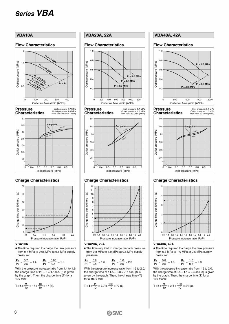
VBA20A, 22A
VBA20A, 22A
Flow Characteristics
Charge Characteristics
Set point
VBA40A, 42A
VBA40A, 42A
P1 = 0.5 MPa
P1 = 0.4 MPaP1 = 0.3 MPa
Flow Characteristics
Charge Characteristics
Set point
VBA10A
VBA10A
Flow Characteristics
PressureCharacteristics
PressureCharacteristics
PressureCharacteristics
Charge Characteristics
P1 = 1.0 MPaP1 = 0.75 MPa
P1 = 0.5 MPaP1 = 0.4 MPa
P1 = 0.3 MPa
P1 = P2
Set point
Inlet pressure: 0.7 MPaOutlet pressure: 1.0 MPa
Flow rate: 20 l /min (ANR)
Inlet pressure: 0.7 MPaOutlet pressure: 1.0 MPa
Flow rate: 20 l /min (ANR)
Inlet pressure: 0.7 MPaOutlet pressure: 1.0 MPa
Flow rate: 20 l /min (ANR)
The time required to charge the tank pressure from 0.7 MPa to 0.95 MPa at 0.5 MPa supply pressure:
With the pressure increase ratio from 1.4 to 1.9, the charge time of 23 – 6 = 17 sec. (t) is given by the graph. Then, the charge time (T) for a 10 l tank:
P2
P1
0.70.5
= = 1.4 = 1.9 = 1.6 = 2.0P2
P1
0.950.5
=
T = t x = 17 x = 17 (s).V10
1010
The time required to charge the tank pressure from 0.8 MPa to 1.0 MPa at 0.5 MPa supply pressure:
With the pressure increase ratio from 1.6 to 2.0, the charge time of 11.5 – 3.8 = 7.7 sec. (t) is given by the graph. Then, the charge time (T) for a 100 l tank:
P2
P1
0.80.5
=P2
P1
1.00.5
=
T = t x = 7.7 x = 77 (s).V10
10010
The time required to charge the tank pressure from 0.8 MPa to 1.0 MPa at 0.5 MPa supply pressure:
With the pressure increase ratio from 1.6 to 2.0, the charge time of 3.5 – 1.1 = 2.4 sec. (t) is given by the graph. Then, the charge time (T) for a 100 l tank:
P2
P1
0.80.5
= = 1.6 = 2.0P2
P1
1.00.5
=
T = t x = 2.4 x = 24 (s).V10
10010
Series VBA
1.6
1.4
1.2
1
0.8
0.6
0.4
0.2
Out
let p
ress
ure
(MP
a)
0 500 1000 1500 2000 2500 3000
Outlet air flow (l/min (ANR))
1.08
1.06
1.04
1.02
1.0
0.98
0.96
0.94
Out
let p
ress
ure
(MP
a)
0 0.4 0.5 0.6 0.7 0.8 0.9 1
Inlet pressure (MPa)
0.1
0.08
0.06
0.04
0.02Max
. pul
satio
n ra
nge
(MP
a)
0 1 2 3 4 5
Capacity (l)
0.1
0.08
0.06
0.04
0.02Max
. pul
satio
n ra
nge
(MP
a)
0 10 20 30 4038
Capacity (l)
400
300
200
100
0
Cha
rge
time
per
10 li
ters
t (
s)
1.0 2.0 3.0 4.0
Pressure increase ratio P2/P1
1.10
1.08
1.06
1.04
1.02
1.0
0.98
0.96
0.94
0.92
Out
let p
ress
ure
(MP
a)
0 0.1 0.2 0.3 0.4 0.5 0.6 0.7 0.8 0.9 1
Inlet pressure (MPa)
2
1
Out
let p
ress
ure
(MP
a)
0 100 13050
Outlet air flow (l/min (ANR))
5
4
3
2
1
0
Cha
rge
time
per
10 li
ters
t (
s)
1.0 1.1 1.2 1.3 1.4 1.5 1.6 1.7 1.8 1.9 2.0
Pressure increase ratio P2/P1
PressureCharacteristics
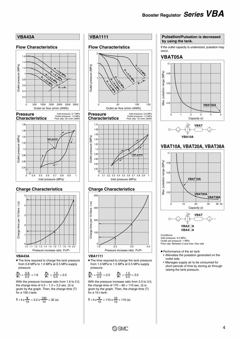
Inlet pressure: 0.6 MPaOutlet pressure: 1.0 MPa
Flow rate: 10 l /min (ANR)
= 2.0 = 3.0
T = t x = 110 x = 110 (s).V10
1010
The time required to charge the tank pressure from 1.0 MPa to 1.5 MPa at 0.5 MPa supply pressure:
With the pressure increase ratio from 2.0 to 3.0, the charge time of 170 – 60 = 110 sec. (t) is given by the graph. Then, the charge time (T) for a 10 l tank:
P2
P1
1.00.5
=P2
P1
1.50.5
=
Pulsation/Pulsation is decreased by using the tank.
If the outlet capacity is undersized, pulsation may occur.
Conditions: Inlet pressure: 0.5 MPaOutlet set pressure: 1 MPa Flow rate: Between 0 and max. flow rate
VBA2AVBA4A
VBAT
VBA10A
• Performance of the air tank • Alleviates the pulsation generated on the
outlet side. • Manages supply air to be consumed for
short periods of time by storing air through raising the tank pressure.
Flow Characteristics
Charge Characteristics
P1 = 0.8 MPa
P1 = 0.7 MPa
P1 = 0.6 MPa
P1 = 0.5 MPa
P1 = P2
VBAT05A
Set point
VBA43A
VBA43A
VBAT05A
VBAT10A, VBAT20A, VBAT38A
VBAT10A
VBAT20AVBAT38A
VBAT
VBA1111
VBA1111
Flow Characteristics
Charge Characteristics
P1 = P2
P1 = 1.0 M
Pa
P1 = 0.75 M
Pa
P1 = 0.5 M
Pa
P1 = 0.4 M
Pa
P1 = 0.3 M
Pa
Set point
PressureCharacteristics
Inlet pressure: 0.7 MPaOutlet pressure: 1.0 MPa
Flow rate: 20 l /min (ANR)
The time required to charge the tank pressure from 0.8 MPa to 1.0 MPa at 0.5 MPa supply pressure:
With the pressure increase ratio from 1.6 to 2.0, the charge time of 4.5 – 1.3 = 3.2 sec. (t) is given by the graph. Then, the charge time (T) for a 100 l tank:
P2
P1
0.80.5
= = 1.6 = 2.0P2
P1
1.00.5
=
T = t x = 3.2 x = 32 (s).V10
10010
Booster Regulator Series VBA
3
12
11
10
9
8
7
6
5
4
3
2
10
Cha
rge
time
per
10 li
ters
t (
s)
1.0 1.1 1.2 1.3 1.4 1.5 1.6 1.7 1.8 1.9 2.0
Pressure increase ratio P2/P1
1.0
0.8
0.6
0.4
0.2
Out
let p
ress
ure
(MP
a)
0 200 400 600 800 1000 1200
Outlet air flow (l/min (ANR))
1.04
1.02
1.0
0.98
0.96
0.94
Out
let p
ress
ure
(MP
a)
0 0.4 0.5 0.6 0.7 0.8 0.9 1
Inlet pressure (MPa)
1.0
0.8
0.6
0.4
0.2
Out
let p
ress
ure
(MP
a)
0 500 1000 1500 2000
Outlet air flow (l/min (ANR))
1.04
1.02
1.0
0.98
0.96
0.94
Out
let p
ress
ure
(MP
a)
0 0.4 0.5 0.6 0.7 0.8 0.9 1
Inlet pressure (MPa)
5
4
3
2
1
0
Cha
rge
time
per
10 li
ters
t (
s)
1.0 1.1 1.2 1.3 1.4 1.5 1.6 1.7 1.8 1.9 2.0
Pressure increase ratio P2/P1
60
50
40
30
20
10
0
Cha
rge
time
per
10 li
ters
t (
s)
1.0 1.2 1.4 1.6 1.8 2.0
Pressure increase ratio P2/P1
2
1.5
1
0.5Out
let p
ress
ure
(MP
a)
0 100 200 300 400
Outlet air flow (l/min (ANR))
1.1
1.05
1.0
0.95
0.9
0.85
0.8
Out
let p
ress
ure
(MP
a)
0 0.50.4 0.6 0.7 0.8 0.9 1
Inlet pressure (MPa)
P1 = 0.5 MPa
P1 = 0.4 MPa
P1 = 0.3 MPa
VBA20A, 22A
VBA20A, 22A
Flow Characteristics
Charge Characteristics
Set point
VBA40A, 42A
VBA40A, 42A
P1 = 0.5 MPa
P1 = 0.4 MPaP1 = 0.3 MPa
Flow Characteristics
Charge Characteristics
Set point
VBA10A
VBA10A
Flow Characteristics
PressureCharacteristics
PressureCharacteristics
PressureCharacteristics
Charge Characteristics
P1 = 1.0 MPaP1 = 0.75 MPa
P1 = 0.5 MPaP1 = 0.4 MPa
P1 = 0.3 MPa
P1 = P2
Set point
Inlet pressure: 0.7 MPaOutlet pressure: 1.0 MPa
Flow rate: 20 l /min (ANR)
Inlet pressure: 0.7 MPaOutlet pressure: 1.0 MPa
Flow rate: 20 l /min (ANR)
Inlet pressure: 0.7 MPaOutlet pressure: 1.0 MPa
Flow rate: 20 l /min (ANR)
The time required to charge the tank pressure from 0.7 MPa to 0.95 MPa at 0.5 MPa supply pressure:
With the pressure increase ratio from 1.4 to 1.9, the charge time of 23 – 6 = 17 sec. (t) is given by the graph. Then, the charge time (T) for a 10 l tank:
P2
P1
0.70.5
= = 1.4 = 1.9 = 1.6 = 2.0P2
P1
0.950.5
=
T = t x = 17 x = 17 (s).V10
1010
The time required to charge the tank pressure from 0.8 MPa to 1.0 MPa at 0.5 MPa supply pressure:
With the pressure increase ratio from 1.6 to 2.0, the charge time of 11.5 – 3.8 = 7.7 sec. (t) is given by the graph. Then, the charge time (T) for a 100 l tank:
P2
P1
0.80.5
=P2
P1
1.00.5
=
T = t x = 7.7 x = 77 (s).V10
10010
The time required to charge the tank pressure from 0.8 MPa to 1.0 MPa at 0.5 MPa supply pressure:
With the pressure increase ratio from 1.6 to 2.0, the charge time of 3.5 – 1.1 = 2.4 sec. (t) is given by the graph. Then, the charge time (T) for a 100 l tank:
P2
P1
0.80.5
= = 1.6 = 2.0P2
P1
1.00.5
=
T = t x = 2.4 x = 24 (s).V10
10010
Series VBA
1.6
1.4
1.2
1
0.8
0.6
0.4
0.2
Out
let p
ress
ure
(MP
a)
0 500 1000 1500 2000 2500 3000
Outlet air flow (l/min (ANR))
1.08
1.06
1.04
1.02
1.0
0.98
0.96
0.94
Out
let p
ress
ure
(MP
a)
0 0.4 0.5 0.6 0.7 0.8 0.9 1
Inlet pressure (MPa)
0.1
0.08
0.06
0.04
0.02Max
. pul
satio
n ra
nge
(MP
a)
0 1 2 3 4 5
Capacity (l)
0.1
0.08
0.06
0.04
0.02Max
. pul
satio
n ra
nge
(MP
a)
0 10 20 30 4038
Capacity (l)
400
300
200
100
0
Cha
rge
time
per
10 li
ters
t (
s)
1.0 2.0 3.0 4.0
Pressure increase ratio P2/P1
1.10
1.08
1.06
1.04
1.02
1.0
0.98
0.96
0.94
0.92
Out
let p
ress
ure
(MP
a)
0 0.1 0.2 0.3 0.4 0.5 0.6 0.7 0.8 0.9 1
Inlet pressure (MPa)
2
1
Out
let p
ress
ure
(MP
a)
0 100 13050
Outlet air flow (l/min (ANR))
5
4
3
2
1
0
Cha
rge
time
per
10 li
ters
t (
s)
1.0 1.1 1.2 1.3 1.4 1.5 1.6 1.7 1.8 1.9 2.0
Pressure increase ratio P2/P1
PressureCharacteristics
Inlet pressure: 0.6 MPaOutlet pressure: 1.0 MPa
Flow rate: 10 l /min (ANR)
= 2.0 = 3.0
T = t x = 110 x = 110 (s).V10
1010
The time required to charge the tank pressure from 1.0 MPa to 1.5 MPa at 0.5 MPa supply pressure:
With the pressure increase ratio from 2.0 to 3.0, the charge time of 170 – 60 = 110 sec. (t) is given by the graph. Then, the charge time (T) for a 10 l tank:
P2
P1
1.00.5
=P2
P1
1.50.5
=
Pulsation/Pulsation is decreased by using the tank.
If the outlet capacity is undersized, pulsation may occur.
Conditions: Inlet pressure: 0.5 MPaOutlet set pressure: 1 MPa Flow rate: Between 0 and max. flow rate
VBA2AVBA4A
VBAT
VBA10A
• Performance of the air tank • Alleviates the pulsation generated on the
outlet side. • Manages supply air to be consumed for
short periods of time by storing air through raising the tank pressure.
Flow Characteristics
Charge Characteristics
P1 = 0.8 MPa
P1 = 0.7 MPa
P1 = 0.6 MPa
P1 = 0.5 MPa
P1 = P2
VBAT05A
Set point
VBA43A
VBA43A
VBAT05A
VBAT10A, VBAT20A, VBAT38A
VBAT10A
VBAT20AVBAT38A
VBAT
VBA1111
VBA1111
Flow Characteristics
Charge Characteristics
P1 = P2
P1 = 1.0 M
Pa
P1 = 0.75 M
Pa
P1 = 0.5 M
Pa
P1 = 0.4 M
Pa
P1 = 0.3 M
Pa
Set point
PressureCharacteristics
Inlet pressure: 0.7 MPaOutlet pressure: 1.0 MPa
Flow rate: 20 l /min (ANR)
The time required to charge the tank pressure from 0.8 MPa to 1.0 MPa at 0.5 MPa supply pressure:
With the pressure increase ratio from 1.6 to 2.0, the charge time of 4.5 – 1.3 = 3.2 sec. (t) is given by the graph. Then, the charge time (T) for a 100 l tank:
P2
P1
0.80.5
= = 1.6 = 2.0P2
P1
1.00.5
=
T = t x = 3.2 x = 32 (s).V10
10010
Booster Regulator Series VBA
4
General line (low pressure) Locations requiring high pressure
VBA
VBA
VBA VBA
Operating pressure: 0.5 MPaBore size: ø100Output: ≈3850N
Operating pressure:0.8 MPaBore size: ø80Output: ≈4000N
0.5 MPa
ø100
IN 0.5 MPa
E
ø80
OUT 0.8 MPa
P2P1
Shortening time
Without check valve by-pass
Time t (S)
Out
let p
ress
ure
(MP
a)
P2
P1
0
Pla
nt li
ne (
sour
ce p
ress
ure)
(Two-stagepressure boost)
VBA22A, VBA42A
IN (Inlet)
GovernorBooster chamber A
Drivechamber A
Switching valve
Piston
Drive chamber B
Booster chamber BCheck valve
OUT(Outlet)
E
Piston rod
Air-operated typePilot pressure
IN (Inlet)
Booster chamber B
Booster chamber A
Piston
Check valve
OUT (Outlet)
Governor
Drive chamber A
E
Drive chamber B
Switchingvalve
Equivalentoutput
Circuit Example
Working Principle
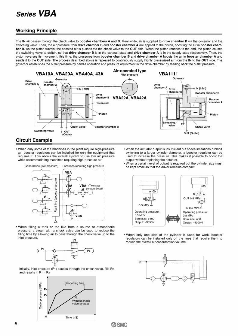
The IN air passes through the check valve to booster chambers A and B. Meanwhile, air is supplied to drive chamber B via the governor and the switching valve. Then, the air pressure from drive chamber B and booster chamber A are applied to the piston, boosting the air in booster cham-ber B. As the piston travels, the boosted air is pushed via the check valve to the OUT side. When the piston reaches to the end, the piston causes the switching valve to switch, so that drive chamber B is in the exhaust state and drive chamber A is in the supply state respectively. Then, the piston reverses its movement, this time, the pressures from booster chamber B and drive chamber A boosts the air in booster chamber A and sends it to the OUT side. The process described above is repeated to continuously supply highly pressurized air from the IN to the OUT side. The governor establishes the outlet pressure by handle operation and pressure adjustment in the drive chamber by feeding back the outlet pressure.
• When only some of the machines in the plant require high-pressure air, booster regulators can be installed for only the equipment that requires it. This allows the overall system to use low air pressure while accommodating machines requiring high-pressure air.
• When the actuator output is insufficient but space limitations prohibit switching to a larger cylinder diameter, a booster regulator can be used to increase the pressure. This makes it possible to boost the output without replacing the actuator.
• When a certain level of output is required but the cylinder size must be kept small so that the driver remains compact.
• When filling a tank or the like from a source at atmospheric pressure, a circuit with a check valve can be used to reduce the filling time by allowing air to pass through the check valve up to the inlet pressure.
• When only one side of the cylinder is used for work, booster regulators can be installed only on the lines that require them to reduce the overall air consumption volume.
VBA1111VBA10A, VBA20A, VBA40A, 43A
Initially, inlet pressure (P1) passes through the check valve, fills P2, and results in P1 = P2.
Series VBA
Tc Ts
øD
LP2P3P1
END
START
1001002001
0.5300.50.8
NO NO
NO
YES
YES YES YES
YES
When running continuously for longer periods of time, confirm the life expectancy. When the life expectancy is shorter than required, select a larger sized booster regulator.
Select the tank from table below.
Avoidpulsation(Max. 0.05
MPa)
Judgementof charge time
T ≤ Ts
Provide requisite conditions for selection.
Calculate required air flow rate Q.
Select booster regula-tor size from flow cha-racteristics table.
Obtain the tank volume V.
Select the tank volume over V.
Calculate time T from charge charac-teristics table.
Increase number of booster regulators (Z) to decrease T.
Tank part no.
VBAT05AVBAT10AVBAT20AVBAT38A
VBA10A
VBA10A
—
—
—
VBA2A
VBA2A
VBA2A
—
—
VBA4A
VBA4A
Applicable combination modelInner volume
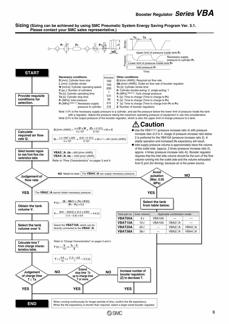
Sizing (Sizing can be achieved by using SMC Pneumatic System Energy Saving Program Ver. 3.1.Please contact your SMC sales representative.)
Lower limit of pressure inside tank P2
Pre
ssur
eS
trok
e
Upper limit of pressure inside tank P3
Inlet pressure P1
Time
Necessary supply pressure to cylinder P2
ExampleNecessary conditions:D [mm]: Cylinder bore sizeL [mm]: Cylinder strokeW [mm/s]: Cylinder operating speedC [pc.]: Number of cylindersTc [s]: Cylinder operating timeTs [s]: Cylinder stop timeP1 [MPa]: Inlet pressureP2 [MPa] Note 1): Necessary supply
pressure to cylinder
Note 1) P2 is the necessary supply pressure to a cylinder, and set the pressure below the lower limit of pressure inside the tank with a regulator. Adjust the pressure taking the maximum operating pressure of equipment in use into consideration.
Note 2) P3 is the output pressure of the booster regulator, which is also the upper limit of charge pressure to a tank.
Other conditions:Q [l/min (ANR)]: Required air flow rateQb [l/min (ANR)]: Outlet air flow rate of booster regulatorTc [s]: Cylinder stroke timeK: Cylinder double-acting: 2, single-acting: 1P3 [MPa] Note 2): Tank charge pressureT1 [s]: Time to charge (Time to charge to P2)T2 [s]: Time to charge (Time to charge to P3)T [s]: Time to charge (Time to charge from P2 to P3)Z: Number of booster regulators
Judgement offlow rate
Q [l/min (ANR)] = π x D2 x W x (P2 + 0.101) x 60 x C
4 x 10⁶ 0.101
Q = π x 1002 x 200 (0.8 + 0.101) x 60 x 1 = 841 [l/min (ANR)]x
4 x 10⁶ 0.101
Refer to “Flow Characteristics” on pages 3 and 4.
VBA2A: Qb = 600 [l/min (ANR)]VBA4A: Qb = 1050 [l/min (ANR)]
NO: Need no tank The VBA4A can supply necessary pressure.
The VBA2A cannot obtain necessary pressure.
(P3 – P2) x 9.9V [l ] =
(Q – Qb/2) x (Tc x K/60)
V = = 4.6 [l ](1.0 – 0.8) x 9.9
Select the VBAT10A, which can be directly connected to the VBA2A.
(841 – 600/2) x (0.5 x 2/60)
Refer to “Charge Characteristics” on pages 3 and 4.
T = ( ) x = 3.5 [s]
T [s] = ( ) x T2 – T1V10
4.610
Z
11.5 – 3.81
Extendstop time Ts
up to charge timeT or more.
Caution Use the VBA1111 (pressure increase ratio 4) with pressure
increase ratio of 2 to 4. Usage of pressure increase ratio below 2 is preferred for the VBA10A (pressure increase ratio 2). A stable operation and increased life expectancy will result.
Inlet supply pressure volume is approximately twice the volume of the outlet side. {approx. 2 times (pressure increase ratio 2), approx. 4 times (pressure increase ratio 4)}. Booster regulator requires that the inlet side volume should be the sum of the flow volume running into the outlet side and the volume exhausted from E port (for driving), because air is the power source.
5 l
10 l
20 l
38 l
Booster Regulator Series VBA
5
General line (low pressure) Locations requiring high pressure
VBA
VBA
VBA VBA
Operating pressure: 0.5 MPaBore size: ø100Output: ≈3850N
Operating pressure:0.8 MPaBore size: ø80Output: ≈4000N
0.5 MPa
ø100
IN 0.5 MPa
E
ø80
OUT 0.8 MPa
P2P1
Shortening time
Without check valve by-pass
Time t (S)
Out
let p
ress
ure
(MP
a)
P2
P1
0
Pla
nt li
ne (
sour
ce p
ress
ure)
(Two-stagepressure boost)
VBA22A, VBA42A
IN (Inlet)
GovernorBooster chamber A
Drivechamber A
Switching valve
Piston
Drive chamber B
Booster chamber BCheck valve
OUT(Outlet)
E
Piston rod
Air-operated typePilot pressure
IN (Inlet)
Booster chamber B
Booster chamber A
Piston
Check valve
OUT (Outlet)
Governor
Drive chamber A
E
Drive chamber B
Switchingvalve
Equivalentoutput
Circuit Example
Working Principle
The IN air passes through the check valve to booster chambers A and B. Meanwhile, air is supplied to drive chamber B via the governor and the switching valve. Then, the air pressure from drive chamber B and booster chamber A are applied to the piston, boosting the air in booster cham-ber B. As the piston travels, the boosted air is pushed via the check valve to the OUT side. When the piston reaches to the end, the piston causes the switching valve to switch, so that drive chamber B is in the exhaust state and drive chamber A is in the supply state respectively. Then, the piston reverses its movement, this time, the pressures from booster chamber B and drive chamber A boosts the air in booster chamber A and sends it to the OUT side. The process described above is repeated to continuously supply highly pressurized air from the IN to the OUT side. The governor establishes the outlet pressure by handle operation and pressure adjustment in the drive chamber by feeding back the outlet pressure.
• When only some of the machines in the plant require high-pressure air, booster regulators can be installed for only the equipment that requires it. This allows the overall system to use low air pressure while accommodating machines requiring high-pressure air.
• When the actuator output is insufficient but space limitations prohibit switching to a larger cylinder diameter, a booster regulator can be used to increase the pressure. This makes it possible to boost the output without replacing the actuator.
• When a certain level of output is required but the cylinder size must be kept small so that the driver remains compact.
• When filling a tank or the like from a source at atmospheric pressure, a circuit with a check valve can be used to reduce the filling time by allowing air to pass through the check valve up to the inlet pressure.
• When only one side of the cylinder is used for work, booster regulators can be installed only on the lines that require them to reduce the overall air consumption volume.
VBA1111VBA10A, VBA20A, VBA40A, 43A
Initially, inlet pressure (P1) passes through the check valve, fills P2, and results in P1 = P2.
Series VBA
Tc Ts
øD
LP2P3P1
END
START
1001002001
0.5300.50.8
NO NO
NO
YES
YES YES YES
YES
When running continuously for longer periods of time, confirm the life expectancy. When the life expectancy is shorter than required, select a larger sized booster regulator.
Select the tank from table below.
Avoidpulsation(Max. 0.05
MPa)
Judgementof charge time
T ≤ Ts
Provide requisite conditions for selection.
Calculate required air flow rate Q.
Select booster regula-tor size from flow cha-racteristics table.
Obtain the tank volume V.
Select the tank volume over V.
Calculate time T from charge charac-teristics table.
Increase number of booster regulators (Z) to decrease T.
Tank part no.
VBAT05AVBAT10AVBAT20AVBAT38A
VBA10A
VBA10A
—
—
—
VBA2A
VBA2A
VBA2A
—
—
VBA4A
VBA4A
Applicable combination modelInner volume
Sizing (Sizing can be achieved by using SMC Pneumatic System Energy Saving Program Ver. 3.1.Please contact your SMC sales representative.)
Lower limit of pressure inside tank P2
Pre
ssur
eS
trok
e
Upper limit of pressure inside tank P3
Inlet pressure P1
Time
Necessary supply pressure to cylinder P2
ExampleNecessary conditions:D [mm]: Cylinder bore sizeL [mm]: Cylinder strokeW [mm/s]: Cylinder operating speedC [pc.]: Number of cylindersTc [s]: Cylinder operating timeTs [s]: Cylinder stop timeP1 [MPa]: Inlet pressureP2 [MPa] Note 1): Necessary supply
pressure to cylinder
Note 1) P2 is the necessary supply pressure to a cylinder, and set the pressure below the lower limit of pressure inside the tank with a regulator. Adjust the pressure taking the maximum operating pressure of equipment in use into consideration.
Note 2) P3 is the output pressure of the booster regulator, which is also the upper limit of charge pressure to a tank.
Other conditions:Q [l/min (ANR)]: Required air flow rateQb [l/min (ANR)]: Outlet air flow rate of booster regulatorTc [s]: Cylinder stroke timeK: Cylinder double-acting: 2, single-acting: 1P3 [MPa] Note 2): Tank charge pressureT1 [s]: Time to charge (Time to charge to P2)T2 [s]: Time to charge (Time to charge to P3)T [s]: Time to charge (Time to charge from P2 to P3)Z: Number of booster regulators
Judgement offlow rate
Q [l/min (ANR)] = π x D2 x W x (P2 + 0.101) x 60 x C
4 x 10⁶ 0.101
Q = π x 1002 x 200 (0.8 + 0.101) x 60 x 1 = 841 [l/min (ANR)]x
4 x 10⁶ 0.101
Refer to “Flow Characteristics” on pages 3 and 4.
VBA2A: Qb = 600 [l/min (ANR)]VBA4A: Qb = 1050 [l/min (ANR)]
NO: Need no tank The VBA4A can supply necessary pressure.
The VBA2A cannot obtain necessary pressure.
(P3 – P2) x 9.9V [l ] =
(Q – Qb/2) x (Tc x K/60)
V = = 4.6 [l ](1.0 – 0.8) x 9.9
Select the VBAT10A, which can be directly connected to the VBA2A.
(841 – 600/2) x (0.5 x 2/60)
Refer to “Charge Characteristics” on pages 3 and 4.
T = ( ) x = 3.5 [s]
T [s] = ( ) x T2 – T1V10
4.610
Z
11.5 – 3.81
Extendstop time Ts
up to charge timeT or more.
Caution Use the VBA1111 (pressure increase ratio 4) with pressure
increase ratio of 2 to 4. Usage of pressure increase ratio below 2 is preferred for the VBA10A (pressure increase ratio 2). A stable operation and increased life expectancy will result.
Inlet supply pressure volume is approximately twice the volume of the outlet side. {approx. 2 times (pressure increase ratio 2), approx. 4 times (pressure increase ratio 4)}. Booster regulator requires that the inlet side volume should be the sum of the flow volume running into the outlet side and the volume exhausted from E port (for driving), because air is the power source.
5 l
10 l
20 l
38 l
Booster Regulator Series VBA
6
Design
Warning1. Warning concerning abnormal outlet pressure
• If there is a likelihood of causing an outlet pressure drop due to unforeseen circumstances such as equipment mal-function, thus leading to a major problem, take safety mea-sures on the system side.
• Because the outlet pressure could exceed its set range if there is a large fluctuation in the inlet pressure, leading to unexpected accidents, take safety measures against abnor-mal pressures.
• Operate the equipment within its maximum operating pres-sure and set pressure range.
2. Residual pressure measures• Connect a 3-port valve to the OUT side of the booster regu-
lator if the residual pressure must be released quickly from the outlet pressure side for maintenance, etc. (Refer to the below diagram.) The residual outlet pressure side cannot be released even if the 3-port valve is connected to the IN side because the check valve in the booster regulator will activa-te.
• After operation is finished, release the supply pressure at the in-let. This stops the booster valve from moving needlessly and prevents operating malfunctions.
Selection
Caution1. Verify the specifications.
• Consider the operating conditions and operate this product within the specification range that is described in this catalo-gue.
2. Selection• Based on the conditions (pressure, flow rate, takt time, etc.)
required for the outlet side of the booster regulator, select the size of the booster regulator in accordance with the se-lection procedures described in this catalogue or model se-lection program.
• Use the VBA1111 (pressure increase ratio 4) with pressure increase ratio of 2 to 4. Usage of pressure increase ratio below 2 is preferred for the VBA10A (pressure increase ra-tio 2). A stable operation and increased life expectancy will result.
• Inlet supply pressure volume is approximately twice the vo-lume of the outlet side. {approx. 2 times (pressure increase ratio 2), approx. 4 times (pressure increase ratio 4)}. Boos-ter regulator requires that the inlet side volume should be the sum of the flow volume running into the outlet side and the volume exhausted from E port (for driving), because air is the power source.
• When running continuously for longer periods of time, con-firm the life expectancy. The life expectancy of a booster re-gulator is dependent upon the operational cycle. Thus, when used for driving cylinders, etc. in the outlet side, life expectancy will be reduced.
• Make sure the outlet pressure is set more than 0.1 MPa hig-her than the inlet pressure. A pressure difference less than 0.1 MPa makes the operation unstable and may result in malfunction.
Mounting
Caution1. Transporting
• When transporting this product, hold it lengthwise with both hands. Never hold it by the black handle that protrudes from the centre because the handle could become detached from the body, causing the body to fall and leading to injury.
2. Installation • Install this product so that the silver-coloured tie-rods and
cover are placed horizontally. If mounted vertically, it may result in malfunction.
• Because the piston cycle vibration is transferred, use the fo-llowing mounting bolts (VBA1: M5; VBA2, 4: M10) and tigh-ten them with the specified torque (VBA1: 3 N·m; VBA2, 4: 24 N·m).
• If the transmission of vibration is not preferred, insert an iso-lating rubber material before installation.
• The pressure gauge should be mounted with the following torque. R 1/16: 3 to 4 N, R 1/8: 7 to 9 N
Piping
Caution1. Flushing
• Use an air blower to flush the piping to thoroughly remove any cutting chips, cutting oil, or debris from the piping insi-de, before connecting them. If they enter the inside of the booster regulator, they could cause the booster regulator to malfunction or its durability could be affected.
2. Piping size• To bring the booster regulator’s ability into full play, make
sure to match the piping size to the port size.
Air Supply
Caution1. Quality of air source
• Connect a mist separator to the inlet side near the booster regulator. If the quality of the compressed air is not tho-roughly controlled, the booster regulator could malfunction (without being able to boost) or its durability could be affec-ted.
• If dry air (atmospheric pressure dew point: –17°C or less) is used, the life expectancy may be shortened because dry air will accelerate evaporation of grease inside.
Operating Environment
Caution1. Installation location
• Do not install this product in an area that is exposed to rain-water or direct sunlight.
• Do not install in locations influenced by vibrations. If it must be used in such an area due to unavoidable circumstances, please contact SMC beforehand.
Series VBA
Handling
1
0.9
0.8
0.7
0.6
0.5
0.5
0.4
0.4
0.3
0.3
0.2
0.2Pilot pressure MPa
0.1
0.10
Out
let p
ress
ure
MP
a (Q
= 0
)
SMC
HighLow
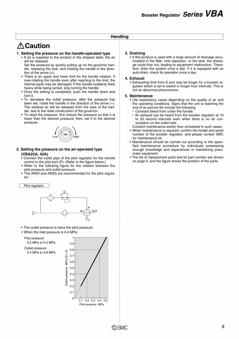
1. Setting the pressure on the handle-operated type• If air is supplied to the product in the shipped state, the air
will be released.Set the pressure by quickly pulling up on the governor han-dle, releasing the lock, and rotating the handle in the direc-tion of the arrow (+).
• There is an upper and lower limit for the handle rotation. If over-rotating the handle even after reaching to the limit, the internal parts may be damaged. If the handle suddenly feels heavy while being turned, stop turning the handle.
• Once the setting is completed, push the handle down and lock it.
• To decrease the outlet pressure, after the pressure has been set, rotate the handle in the direction of the arrow (–). The residual air will be released from the area of the han-dle, due to the relief construction of the governor.
• To reset the pressure, first reduce the pressure so that it is lower than the desired pressure; then, set it to the desired pressure.
Caution
2. Setting the pressure on the air-operated type (VBA22A, 42A)• Connect the outlet pipe of the pilot regulator for the remote
control to the pilot port (P). (Refer to the figure below.)• Refer to the following figure for the relation between the
pilot pressure and outlet pressure.• The AR20 and AW20 are recommended for the pilot regula-
tor.
Pilot regulator
• The outlet pressure is twice the pilot pressure.• When the inlet pressure is 0.4 MPa:
Pilot pressure0.2 MPa to 0.4 MPa
Outlet pressure0.4 MPa to 0.8 MPa
3. Draining• If this product is used with a large amount of drainage accu-
mulated in the filter, mist separator, or the tank, the draina-ge could flow out, leading to equipment malfunction. There-fore, drain the system once a day. If it is equipped with an auto-drain, check its operation once a day.
4. Exhaust• Exhausting time from E port may be longer for a booster re-
gulator which is set to switch in longer hour intervals. This is not an abnormal phenomenon.
5. Maintenance• Life expectancy varies depending on the quality of air and
the operating conditions. Signs that the unit is reaching the end of its service life include the following:• Constant bleed from under the handle.• Air exhaust can be heard from the booster regulator at 10
to 20 second intervals even when there is no air con-sumption on the outlet side.
Conduct maintenance earlier than scheduled in such cases.• When maintenance is required, confirm the model and serial
number of the booster regulator, and please contact SMC for maintenance kit.
• Maintenance should be carried out according to the speci-fied maintenance procedure by individuals possessing enough knowledge and experiences in maintaining pneu-matic equipment.
• The list of replacement parts and kit part number are shown on page 9, and the figure shows the position of the parts.
Booster Regulator Series VBA
7
Design
Warning1. Warning concerning abnormal outlet pressure
• If there is a likelihood of causing an outlet pressure drop due to unforeseen circumstances such as equipment mal-function, thus leading to a major problem, take safety mea-sures on the system side.
• Because the outlet pressure could exceed its set range if there is a large fluctuation in the inlet pressure, leading to unexpected accidents, take safety measures against abnor-mal pressures.
• Operate the equipment within its maximum operating pres-sure and set pressure range.
2. Residual pressure measures• Connect a 3-port valve to the OUT side of the booster regu-
lator if the residual pressure must be released quickly from the outlet pressure side for maintenance, etc. (Refer to the below diagram.) The residual outlet pressure side cannot be released even if the 3-port valve is connected to the IN side because the check valve in the booster regulator will activa-te.
• After operation is finished, release the supply pressure at the in-let. This stops the booster valve from moving needlessly and prevents operating malfunctions.
Selection
Caution1. Verify the specifications.
• Consider the operating conditions and operate this product within the specification range that is described in this catalo-gue.
2. Selection• Based on the conditions (pressure, flow rate, takt time, etc.)
required for the outlet side of the booster regulator, select the size of the booster regulator in accordance with the se-lection procedures described in this catalogue or model se-lection program.
• Use the VBA1111 (pressure increase ratio 4) with pressure increase ratio of 2 to 4. Usage of pressure increase ratio below 2 is preferred for the VBA10A (pressure increase ra-tio 2). A stable operation and increased life expectancy will result.
• Inlet supply pressure volume is approximately twice the vo-lume of the outlet side. {approx. 2 times (pressure increase ratio 2), approx. 4 times (pressure increase ratio 4)}. Boos-ter regulator requires that the inlet side volume should be the sum of the flow volume running into the outlet side and the volume exhausted from E port (for driving), because air is the power source.
• When running continuously for longer periods of time, con-firm the life expectancy. The life expectancy of a booster re-gulator is dependent upon the operational cycle. Thus, when used for driving cylinders, etc. in the outlet side, life expectancy will be reduced.
• Make sure the outlet pressure is set more than 0.1 MPa hig-her than the inlet pressure. A pressure difference less than 0.1 MPa makes the operation unstable and may result in malfunction.
Mounting
Caution1. Transporting
• When transporting this product, hold it lengthwise with both hands. Never hold it by the black handle that protrudes from the centre because the handle could become detached from the body, causing the body to fall and leading to injury.
2. Installation • Install this product so that the silver-coloured tie-rods and
cover are placed horizontally. If mounted vertically, it may result in malfunction.
• Because the piston cycle vibration is transferred, use the fo-llowing mounting bolts (VBA1: M5; VBA2, 4: M10) and tigh-ten them with the specified torque (VBA1: 3 N·m; VBA2, 4: 24 N·m).
• If the transmission of vibration is not preferred, insert an iso-lating rubber material before installation.
• The pressure gauge should be mounted with the following torque. R 1/16: 3 to 4 N, R 1/8: 7 to 9 N
Piping
Caution1. Flushing
• Use an air blower to flush the piping to thoroughly remove any cutting chips, cutting oil, or debris from the piping insi-de, before connecting them. If they enter the inside of the booster regulator, they could cause the booster regulator to malfunction or its durability could be affected.
2. Piping size• To bring the booster regulator’s ability into full play, make
sure to match the piping size to the port size.
Air Supply
Caution1. Quality of air source
• Connect a mist separator to the inlet side near the booster regulator. If the quality of the compressed air is not tho-roughly controlled, the booster regulator could malfunction (without being able to boost) or its durability could be affec-ted.
• If dry air (atmospheric pressure dew point: –17°C or less) is used, the life expectancy may be shortened because dry air will accelerate evaporation of grease inside.
Operating Environment
Caution1. Installation location
• Do not install this product in an area that is exposed to rain-water or direct sunlight.
• Do not install in locations influenced by vibrations. If it must be used in such an area due to unavoidable circumstances, please contact SMC beforehand.
Series VBA
Handling
1
0.9
0.8
0.7
0.6
0.5
0.5
0.4
0.4
0.3
0.3
0.2
0.2Pilot pressure MPa
0.1
0.10
Out
let p
ress
ure
MP
a (Q
= 0
)
SMC
HighLow
1. Setting the pressure on the handle-operated type• If air is supplied to the product in the shipped state, the air
will be released.Set the pressure by quickly pulling up on the governor han-dle, releasing the lock, and rotating the handle in the direc-tion of the arrow (+).
• There is an upper and lower limit for the handle rotation. If over-rotating the handle even after reaching to the limit, the internal parts may be damaged. If the handle suddenly feels heavy while being turned, stop turning the handle.
• Once the setting is completed, push the handle down and lock it.
• To decrease the outlet pressure, after the pressure has been set, rotate the handle in the direction of the arrow (–). The residual air will be released from the area of the han-dle, due to the relief construction of the governor.
• To reset the pressure, first reduce the pressure so that it is lower than the desired pressure; then, set it to the desired pressure.
Caution
2. Setting the pressure on the air-operated type (VBA22A, 42A)• Connect the outlet pipe of the pilot regulator for the remote
control to the pilot port (P). (Refer to the figure below.)• Refer to the following figure for the relation between the
pilot pressure and outlet pressure.• The AR20 and AW20 are recommended for the pilot regula-
tor.
Pilot regulator
• The outlet pressure is twice the pilot pressure.• When the inlet pressure is 0.4 MPa:
Pilot pressure0.2 MPa to 0.4 MPa
Outlet pressure0.4 MPa to 0.8 MPa
3. Draining• If this product is used with a large amount of drainage accu-
mulated in the filter, mist separator, or the tank, the draina-ge could flow out, leading to equipment malfunction. There-fore, drain the system once a day. If it is equipped with an auto-drain, check its operation once a day.
4. Exhaust• Exhausting time from E port may be longer for a booster re-
gulator which is set to switch in longer hour intervals. This is not an abnormal phenomenon.
5. Maintenance• Life expectancy varies depending on the quality of air and
the operating conditions. Signs that the unit is reaching the end of its service life include the following:• Constant bleed from under the handle.• Air exhaust can be heard from the booster regulator at 10
to 20 second intervals even when there is no air con-sumption on the outlet side.
Conduct maintenance earlier than scheduled in such cases.• When maintenance is required, confirm the model and serial
number of the booster regulator, and please contact SMC for maintenance kit.
• Maintenance should be carried out according to the speci-fied maintenance procedure by individuals possessing enough knowledge and experiences in maintaining pneu-matic equipment.
• The list of replacement parts and kit part number are shown on page 9, and the figure shows the position of the parts.
Booster Regulator Series VBA
8
Air-operated type
VBA22A, 42A
VBA1111
VBA10A VBA20A, 22A, VBA40A, 42A, 43A
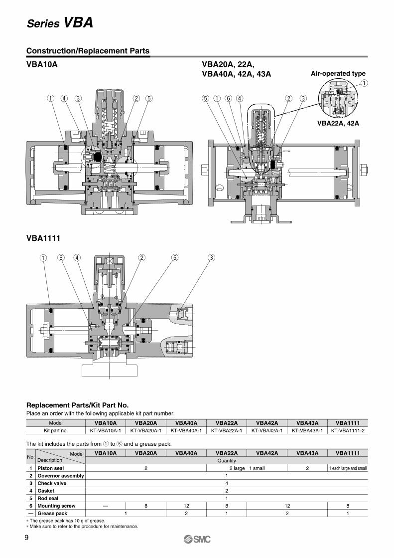
Replacement Parts/Kit Part No.
The kit includes the parts from to and a grease pack.
ModelNo.
1
2
3
4
5
6
—
Piston seal
Governor assembly
Check valve
Gasket
Rod seal
Mounting screw
Grease pack
Description
Place an order with the following applicable kit part number.
Model
Kit part no.
VBA43A VBA1111VBA42AVBA22AVBA40AVBA20AVBA10AKT-VBA10A-1 KT-VBA20A-1 KT-VBA40A-1 KT-VBA22A-1 KT-VBA42A-1 KT-VBA43A-1 KT-VBA1111-2
VBA43A VBA1111VBA42AVBA22AVBA40AVBA20AVBA10AQuantity
2
4
2
1
8
1
— 8 12
21
1
8
1
12
2
1 each large and small2 large 1 small 2
∗ The grease pack has 10 g of grease.∗ Make sure to refer to the procedure for maintenance.
Construction/Replacement Parts
Series VBA
28
21
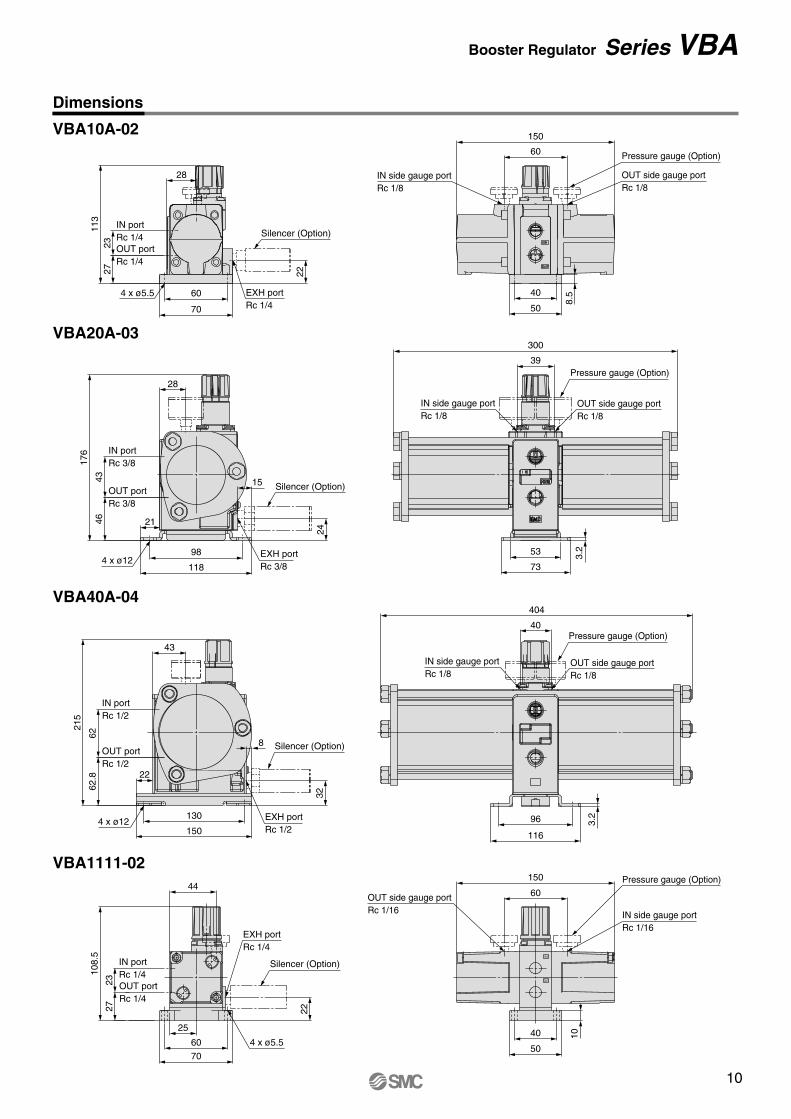
98
118
176
4643
OUT portRc 3/8
IN portRc 3/8
Silencer (Option)
4 x ø12EXH portRc 3/8
15
24
IN side gauge portRc 1/8
300
39
OUT side gauge portRc 1/8
Pressure gauge (Option)
3.253
73
43
22
130
150
215
62.8
62
OUT portRc 1/2
IN portRc 1/2
Silencer (Option)
EXH portRc 1/2
EXH portRc 1/4
8
32
4 x ø12
IN side gauge portRc 1/8
404
40
OUT side gauge portRc 1/8
Pressure gauge (Option)
3.296
116
150
60
IN side gauge portRc 1/8
OUT side gauge portRc 1/8
Pressure gauge (Option)
40
8.5
50
113
2723 OUT port
Rc 1/4
IN portRc 1/4
4 x ø5.5 EXH portRc 1/4
Silencer (Option)
60
70
22
28
IN
OUT
4 x ø5.5
Pressure gauge (Option)
IN portRc 1/4OUT portRc 1/4
Silencer (Option)
IN side gauge portRc 1/16
OUT side gauge portRc 1/16
40 10
50
60
150
60
70
2723
108.
5
22
25
44
VBA10A-02
VBA1111-02
VBA20A-03
VBA40A-04
Dimensions
Booster Regulator Series VBA
9
Air-operated type
VBA22A, 42A
VBA1111
VBA10A VBA20A, 22A, VBA40A, 42A, 43A
Replacement Parts/Kit Part No.
The kit includes the parts from to and a grease pack.
ModelNo.
1
2
3
4
5
6
—
Piston seal
Governor assembly
Check valve
Gasket
Rod seal
Mounting screw
Grease pack
Description
Place an order with the following applicable kit part number.
Model
Kit part no.
VBA43A VBA1111VBA42AVBA22AVBA40AVBA20AVBA10AKT-VBA10A-1 KT-VBA20A-1 KT-VBA40A-1 KT-VBA22A-1 KT-VBA42A-1 KT-VBA43A-1 KT-VBA1111-2
VBA43A VBA1111VBA42AVBA22AVBA40AVBA20AVBA10AQuantity
2
4
2
1
8
1
— 8 12
21
1
8
1
12
2
1 each large and small2 large 1 small 2
∗ The grease pack has 10 g of grease.∗ Make sure to refer to the procedure for maintenance.
Construction/Replacement Parts
Series VBA
28
21
98
118
176
4643
OUT portRc 3/8
IN portRc 3/8
Silencer (Option)
4 x ø12EXH portRc 3/8
15
24
IN side gauge portRc 1/8
300
39
OUT side gauge portRc 1/8
Pressure gauge (Option)
3.253
73
43
22
130
150
215
62.8
62
OUT portRc 1/2
IN portRc 1/2
Silencer (Option)
EXH portRc 1/2
EXH portRc 1/4
8
32
4 x ø12
IN side gauge portRc 1/8
404
40
OUT side gauge portRc 1/8
Pressure gauge (Option)
3.296
116
150
60
IN side gauge portRc 1/8
OUT side gauge portRc 1/8
Pressure gauge (Option)
40
8.5
50
113
2723 OUT port
Rc 1/4
IN portRc 1/4
4 x ø5.5 EXH portRc 1/4
Silencer (Option)
60
7022
28
IN
OUT
4 x ø5.5
Pressure gauge (Option)
IN portRc 1/4OUT portRc 1/4
Silencer (Option)
IN side gauge portRc 1/16
OUT side gauge portRc 1/16
40 10
50
60
150
60
70
2723
108.
5
22
25
44
VBA10A-02
VBA1111-02
VBA20A-03
VBA40A-04
Dimensions
Booster Regulator Series VBA
10
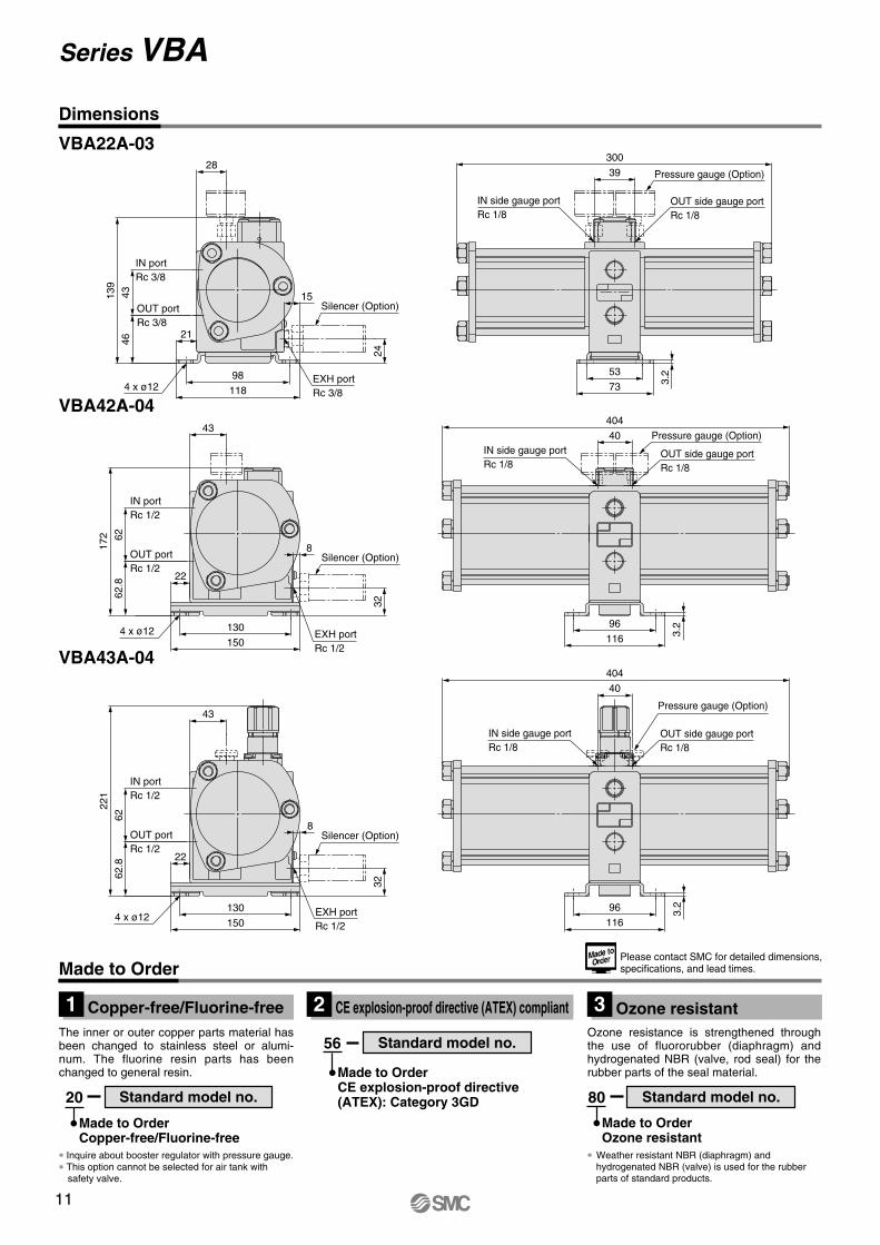
21
15
24
464313
9
28
3.2
Silencer (Option)
EXH portRc 3/8
4 x ø12
OUT portRc 3/8
IN portRc 3/8
Pressure gauge (Option)
OUT side gauge portRc 1/8
IN side gauge portRc 1/8
43
172
62.8
62
32
8
22
3.2
Pressure gauge (Option)IN side gauge portRc 1/8
OUT side gauge portRc 1/8
4 x ø12 EXH portRc 1/2
Silencer (Option)OUT portRc 1/2
IN portRc 1/2
221
32
8
22
43
62.8
62
3.2
Pressure gauge (Option)
OUT side gauge portRc 1/8
IN side gauge portRc 1/8
Silencer (Option)
EXH portRc 1/2
4 x ø12
OUT portRc 1/2
IN portRc 1/2
39
73
53
300
40
404
96
116
116
96
40
404
118
98
130
150
150
130
VBA22A-03
VBA42A-04
VBA43A-04
The inner or outer copper parts material has been changed to stainless steel or alumi-num. The fluorine resin parts has been changed to general resin.
20
Made to OrderCopper-free/Fluorine-free
56
Made to OrderCE explosion-proof directive(ATEX): Category 3GD
Ozone resistance is strengthened through the use of fluororubber (diaphragm) and hydrogenated NBR (valve, rod seal) for the rubber parts of the seal material.
∗ Inquire about booster regulator with pressure gauge. ∗ This option cannot be selected for air tank with
safety valve.
∗ Weather resistant NBR (diaphragm) and hydrogenated NBR (valve) is used for the rubber parts of standard products.
80
Made to OrderOzone resistant
Standard model no.
Standard model no.
Standard model no.
Made to OrderPlease contact SMC for detailed dimensions, specifications, and lead times.
Dimensions
Copper-free/Fluorine-free1 CE explosion-proof directive (ATEX) compliant2 Ozone resistant3
Series VBA
11
21
15
24
464313
9
28
3.2
Silencer (Option)
EXH portRc 3/8
4 x ø12
OUT portRc 3/8
IN portRc 3/8
Pressure gauge (Option)
OUT side gauge portRc 1/8
IN side gauge portRc 1/8
43
172
62.8
62
32
8
22
3.2
Pressure gauge (Option)IN side gauge portRc 1/8
OUT side gauge portRc 1/8
4 x ø12 EXH portRc 1/2
Silencer (Option)OUT portRc 1/2
IN portRc 1/2
221
32
8
22
43
62.8
62
3.2
Pressure gauge (Option)
OUT side gauge portRc 1/8
IN side gauge portRc 1/8
Silencer (Option)
EXH portRc 1/2
4 x ø12
OUT portRc 1/2
IN portRc 1/2
39
73
53
300
40
404
96
116
116
96
40
404
118
98
130
150
150
130
VBA22A-03
VBA42A-04
VBA43A-04
The inner or outer copper parts material has been changed to stainless steel or alumi-num. The fluorine resin parts has been changed to general resin.
20
Made to OrderCopper-free/Fluorine-free
56
Made to OrderCE explosion-proof directive(ATEX): Category 3GD
Ozone resistance is strengthened through the use of fluororubber (diaphragm) and hydrogenated NBR (valve, rod seal) for the rubber parts of the seal material.
∗ Inquire about booster regulator with pressure gauge. ∗ This option cannot be selected for air tank with
safety valve.
∗ Weather resistant NBR (diaphragm) and hydrogenated NBR (valve) is used for the rubber parts of standard products.
80
Made to OrderOzone resistant
Standard model no.
Standard model no.
Standard model no.
Made to OrderPlease contact SMC for detailed dimensions, specifications, and lead times.
Dimensions
Copper-free/Fluorine-free1 CE explosion-proof directive (ATEX) compliant2 Ozone resistant3
Series VBA
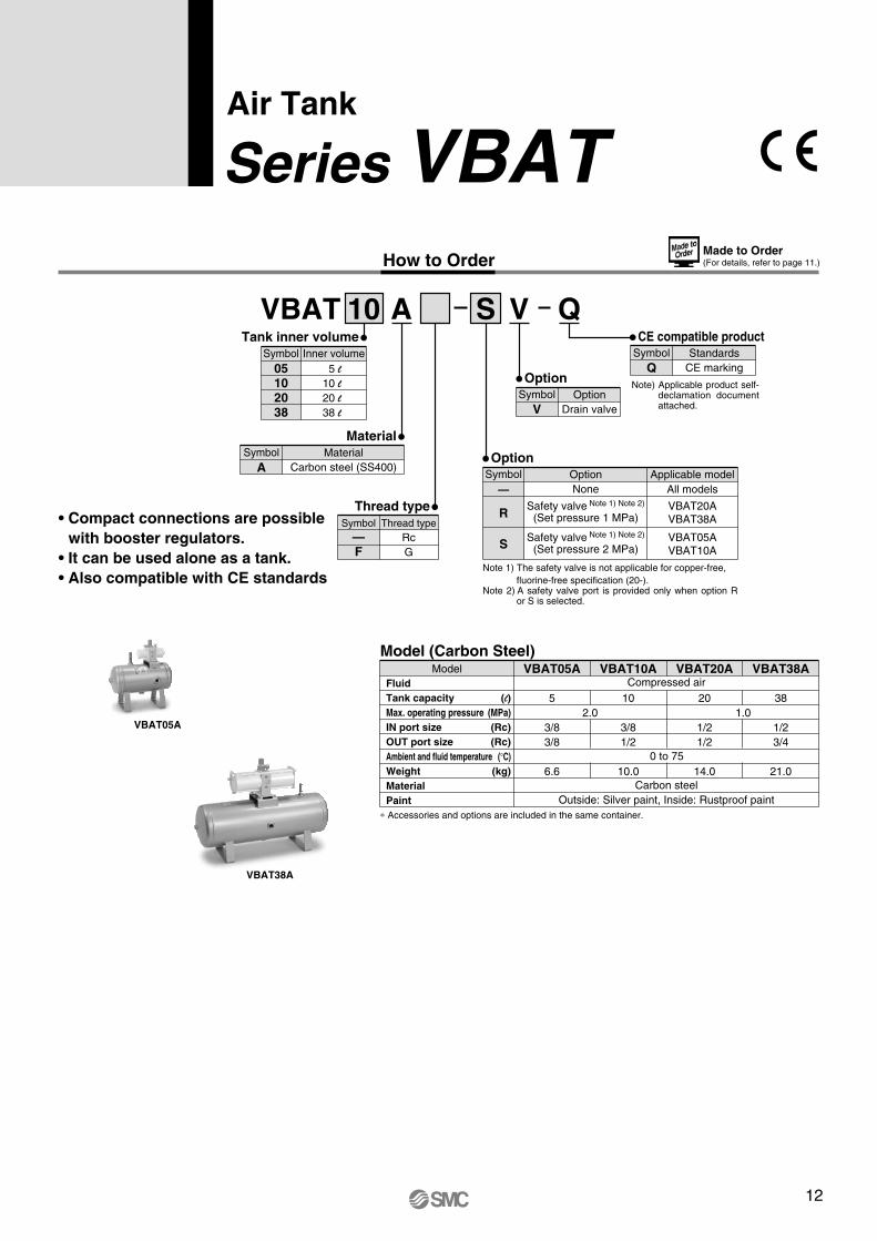
Model (Carbon Steel)Model
FluidTank capacity (l)Max. operating pressure (MPa)IN port size (Rc)OUT port size (Rc)Ambient and fluid temperature (°C)Weight (kg)MaterialPaint
VBAT05A
5 102.0
0 to 75
Carbon steelOutside: Silver paint, Inside: Rustproof paint
1.020 38
3/83/8
6.6
3/81/2
10.0
1/21/2
14.0
1/23/4
21.0
VBAT10A VBAT20A VBAT38A
∗ Accessories and options are included in the same container.
Compressed air
VBAT05A
VBAT38A
VBAT 10 A
MaterialCarbon steel (SS400)
MaterialSymbol
A
Inner volume5 l
10 l20 l38 l
Tank inner volumeSymbol
05102038
Thread typeRcG
Thread typeSymbol
—F
S
Note 1) The safety valve is not applicable for copper-free, fluorine-free specification (20-).
Note 2) A safety valve port is provided only when option R or S is selected.
Note) Applicable product self-declamation document attached.
OptionNone
Safety valve Note 1) Note 2)
(Set pressure 1 MPa)
Applicable modelAll models
VBAT20AVBAT38A
OptionSymbol
—
R
Safety valve Note 1) Note 2)
(Set pressure 2 MPa)VBAT05AVBAT10AS
OptionDrain valve
OptionSymbol
V
StandardsCE marking
CE compatible productSymbol
Q
• Compact connections are possible with booster regulators.
• It can be used alone as a tank. • Also compatible with CE standards
How to Order
Air Tank
Series VBATMade to Order(For details, refer to page 11.)
QV
12
Drain valve
Safety valve IN PORTR1/4
19
OUT PORTRc 1/8
20
ø30
58 (
CLO
SE
) to
63
(O
PE
N)
Safety valveVBAT-R, VBAT-S
Drain valveVBAT-V1
52
65
R 3/8
19
ø18.5
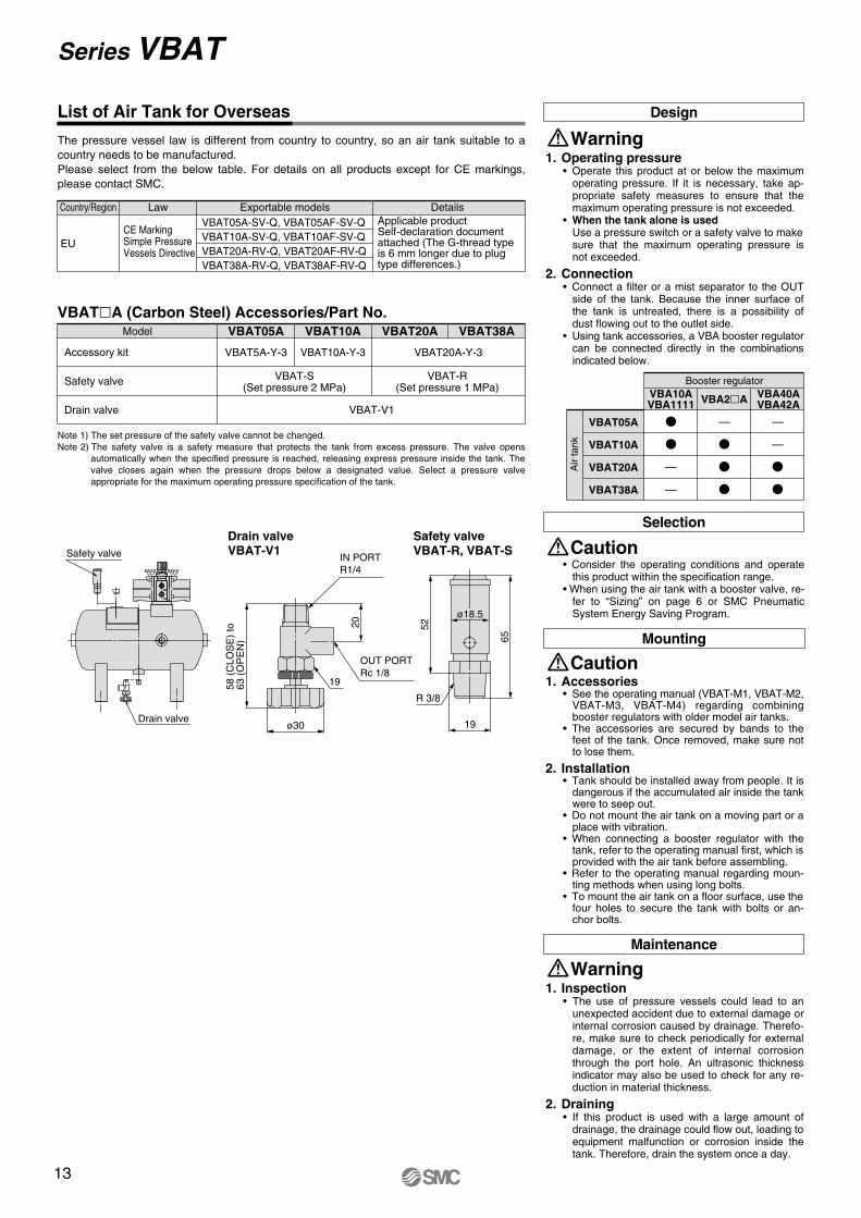
EUCE MarkingSimple PressureVessels Directive
Applicable productSelf-declaration document attached (The G-thread type is 6 mm longer due to plug type differences.)
VBAT05A-SV-Q, VBAT05AF-SV-QVBAT10A-SV-Q, VBAT10AF-SV-QVBAT20A-RV-Q, VBAT20AF-RV-QVBAT38A-RV-Q, VBAT38AF-RV-Q
Country/Region Law Exportable models Details
Model VBAT05A VBAT10A VBAT20A VBAT38AVBATA (Carbon Steel) Accessories/Part No.
VBAT5A-Y-3
VBAT-V1
VBAT10A-Y-3 VBAT20A-Y-3
Note 1) The set pressure of the safety valve cannot be changed.Note 2) The safety valve is a safety measure that protects the tank from excess pressure. The valve opens
automatically when the specified pressure is reached, releasing express pressure inside the tank. The valve closes again when the pressure drops below a designated value. Select a pressure valve appropriate for the maximum operating pressure specification of the tank.
VBAT-S(Set pressure 2 MPa)
VBAT-R(Set pressure 1 MPa)
Booster regulator
VBA2AVBA10AVBA1111
VBA40AVBA42A
—
—
—
—
—
The pressure vessel law is different from country to country, so an air tank suitable to a country needs to be manufactured.Please select from the below table. For details on all products except for CE markings, please contact SMC.
Drain valve
Safety valve
VBAT05A
VBAT10A
VBAT20A
VBAT38A
List of Air Tank for Overseas
Accessory kit
Design
Warning1. Operating pressure
• Operate this product at or below the maximum operating pressure. If it is necessary, take ap-propriate safety measures to ensure that the maximum operating pressure is not exceeded.
• When the tank alone is usedUse a pressure switch or a safety valve to make sure that the maximum operating pressure is not exceeded.
2. Connection• Connect a filter or a mist separator to the OUT
side of the tank. Because the inner surface of the tank is untreated, there is a possibility of dust flowing out to the outlet side.
• Using tank accessories, a VBA booster regulator can be connected directly in the combinations indicated below.
Air
tank
Selection
Caution• Consider the operating conditions and operate
this product within the specification range.• When using the air tank with a booster valve, re-
fer to “Sizing” on page 6 or SMC Pneumatic System Energy Saving Program.
1. Inspection• The use of pressure vessels could lead to an
unexpected accident due to external damage or internal corrosion caused by drainage. Therefo-re, make sure to check periodically for external damage, or the extent of internal corrosion through the port hole. An ultrasonic thickness indicator may also be used to check for any re-duction in material thickness.
2. Draining• If this product is used with a large amount of
drainage, the drainage could flow out, leading to equipment malfunction or corrosion inside the tank. Therefore, drain the system once a day.
Maintenance
Warning
1. Accessories• See the operating manual (VBAT-M1, VBAT-M2,
VBAT-M3, VBAT-M4) regarding combining booster regulators with older model air tanks.
• The accessories are secured by bands to the feet of the tank. Once removed, make sure not to lose them.
2. Installation• Tank should be installed away from people. It is
dangerous if the accumulated air inside the tank were to seep out.
• Do not mount the air tank on a moving part or a place with vibration.
• When connecting a booster regulator with the tank, refer to the operating manual first, which is provided with the air tank before assembling.
• Refer to the operating manual regarding moun-ting methods when using long bolts.
• To mount the air tank on a floor surface, use the four holes to secure the tank with bolts or an-chor bolts.
Mounting
Caution
Series VBAT
442∗
(417
)
ø180
(367
)
180120
EXH: Rc3/8
4 x ø11
Booster regulator IN port
Rc 3/8
OUT
Booster regulator IN portRc 3/8
120180
(454
)
(367
)
OUT
4 x ø11
EXH: Rc 3/8
ø180
Booster regulator IN portRc 1/4
OUT
(307
)(A)
EXH: Rc1/4
4 x ø11
100160
ø156
Booster regulator IN portRc 1/4
OUT(A)
(328
)
EXH: Rc1/4
4 x ø11
120
180
ø180
Tank OUT portRc 3/8
200
163
257
338349∗
6060
3232
Drain portRc 1/4
Inspection port2 x Rc 1/2
Tank IN portRc 3/8
Tank OUT portRc 1/2
170
278
60130
3232
Drain portRc 1/4312
460471∗
Inspection port2 x Rc 1/2
Tank IN portRc 3/8
Safety valve portRc 3/8
Safety valve portRc 3/8
Safety valve portRc 3/8
Tank OUT portRc 1/2
Drain portRc 1/4
278
170
312
60130
460471 ∗
3232
Inspection port2 x Rc 1/2
Tank IN portRc 3/8
Connected to VBA20A
∗ The length may be longer than the specification if the plugs mounted on the tank are not fit to the end.
∗ The length may be longer than the specification if the plugs mounted on the tank are not fit to the end.
∗ The length may be longer than the specification if the plugs mounted on the tank are not fit to the end.
A
370 365.5
Connected to VBA22A
Booster regulatormodel
VBA10AVBA1111
A
391 386.5
Booster regulatormodel
VBA10AVBA1111
Connected to VBA10A, 1111VBAT05A Material: Carbon steel
Material: Carbon steel
Connected to VBA10A, 1111VBAT10A
Dimensions
Air Tank Series VBAT
13
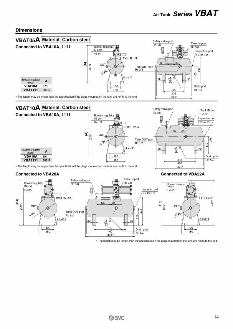
Drain valve
Safety valve IN PORTR1/4
19
OUT PORTRc 1/8
20
ø30
58 (
CLO
SE
) to
63
(O
PE
N)
Safety valveVBAT-R, VBAT-S
Drain valveVBAT-V1
52
65
R 3/8
19
ø18.5
EUCE MarkingSimple PressureVessels Directive
Applicable productSelf-declaration document attached (The G-thread type is 6 mm longer due to plug type differences.)
VBAT05A-SV-Q, VBAT05AF-SV-QVBAT10A-SV-Q, VBAT10AF-SV-QVBAT20A-RV-Q, VBAT20AF-RV-QVBAT38A-RV-Q, VBAT38AF-RV-Q
Country/Region Law Exportable models Details
Model VBAT05A VBAT10A VBAT20A VBAT38AVBATA (Carbon Steel) Accessories/Part No.
VBAT5A-Y-3
VBAT-V1
VBAT10A-Y-3 VBAT20A-Y-3
Note 1) The set pressure of the safety valve cannot be changed.Note 2) The safety valve is a safety measure that protects the tank from excess pressure. The valve opens
automatically when the specified pressure is reached, releasing express pressure inside the tank. The valve closes again when the pressure drops below a designated value. Select a pressure valve appropriate for the maximum operating pressure specification of the tank.
VBAT-S(Set pressure 2 MPa)
VBAT-R(Set pressure 1 MPa)
Booster regulator
VBA2AVBA10AVBA1111
VBA40AVBA42A
—
—
—
—
—
The pressure vessel law is different from country to country, so an air tank suitable to a country needs to be manufactured.Please select from the below table. For details on all products except for CE markings, please contact SMC.
Drain valve
Safety valve
VBAT05A
VBAT10A
VBAT20A
VBAT38A
List of Air Tank for Overseas
Accessory kit
Design
Warning1. Operating pressure
• Operate this product at or below the maximum operating pressure. If it is necessary, take ap-propriate safety measures to ensure that the maximum operating pressure is not exceeded.
• When the tank alone is usedUse a pressure switch or a safety valve to make sure that the maximum operating pressure is not exceeded.
2. Connection• Connect a filter or a mist separator to the OUT
side of the tank. Because the inner surface of the tank is untreated, there is a possibility of dust flowing out to the outlet side.
• Using tank accessories, a VBA booster regulator can be connected directly in the combinations indicated below.
Air
tank
Selection
Caution• Consider the operating conditions and operate
this product within the specification range.• When using the air tank with a booster valve, re-
fer to “Sizing” on page 6 or SMC Pneumatic System Energy Saving Program.
1. Inspection• The use of pressure vessels could lead to an
unexpected accident due to external damage or internal corrosion caused by drainage. Therefo-re, make sure to check periodically for external damage, or the extent of internal corrosion through the port hole. An ultrasonic thickness indicator may also be used to check for any re-duction in material thickness.
2. Draining• If this product is used with a large amount of
drainage, the drainage could flow out, leading to equipment malfunction or corrosion inside the tank. Therefore, drain the system once a day.
Maintenance
Warning
1. Accessories• See the operating manual (VBAT-M1, VBAT-M2,
VBAT-M3, VBAT-M4) regarding combining booster regulators with older model air tanks.
• The accessories are secured by bands to the feet of the tank. Once removed, make sure not to lose them.
2. Installation• Tank should be installed away from people. It is
dangerous if the accumulated air inside the tank were to seep out.
• Do not mount the air tank on a moving part or a place with vibration.
• When connecting a booster regulator with the tank, refer to the operating manual first, which is provided with the air tank before assembling.
• Refer to the operating manual regarding moun-ting methods when using long bolts.
• To mount the air tank on a floor surface, use the four holes to secure the tank with bolts or an-chor bolts.
Mounting
Caution
Series VBAT
442∗
(417
)
ø180
(367
)
180120
EXH: Rc3/8
4 x ø11
Booster regulator IN port
Rc 3/8
OUT
Booster regulator IN portRc 3/8
120180
(454
)
(367
)
OUT
4 x ø11
EXH: Rc 3/8
ø180
Booster regulator IN portRc 1/4
OUT
(307
)(A)
EXH: Rc1/4
4 x ø11
100160
ø156
Booster regulator IN portRc 1/4
OUT(A)
(328
)
EXH: Rc1/4
4 x ø11
120
180
ø180
Tank OUT portRc 3/8
200
163
257
338349∗
6060
3232
Drain portRc 1/4
Inspection port2 x Rc 1/2
Tank IN portRc 3/8
Tank OUT portRc 1/2
170
278
60130
3232
Drain portRc 1/4312
460471∗
Inspection port2 x Rc 1/2
Tank IN portRc 3/8
Safety valve portRc 3/8
Safety valve portRc 3/8
Safety valve portRc 3/8
Tank OUT portRc 1/2
Drain portRc 1/4
278
170
312
60130
460471 ∗
3232
Inspection port2 x Rc 1/2
Tank IN portRc 3/8
Connected to VBA20A
∗ The length may be longer than the specification if the plugs mounted on the tank are not fit to the end.
∗ The length may be longer than the specification if the plugs mounted on the tank are not fit to the end.
∗ The length may be longer than the specification if the plugs mounted on the tank are not fit to the end.
A
370 365.5
Connected to VBA22A
Booster regulatormodel
VBA10AVBA1111
A
391 386.5
Booster regulatormodel
VBA10AVBA1111
Connected to VBA10A, 1111VBAT05A Material: Carbon steel
Material: Carbon steel
Connected to VBA10A, 1111VBAT10A
Dimensions
Air Tank Series VBAT
14
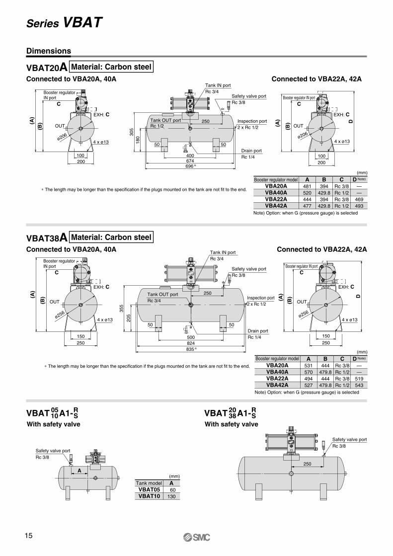
ø256
(A)
(B) D
250
150
Booster regulator IN portC
OUT
EXH: C
4 x ø13
Tank OUT portRc 3/4
Drain portRc 1/4
355
205
500
5050
824835 ∗
Tank IN portRc 3/4
Inspection port2 x Rc 1/2
C
150250
(A)
(B)
OUT
4 x ø13
EXH: C
ø256
Booster regulator IN port
(A) D
(B)
ø206
200100
EXH: C
OUT
Booster regulator IN portC
4 x ø13
Inspection port2 x Rc 1/2
Tank OUT portRc 1/2
Drain portRc 1/4
305
180
50
250
250
50
696 ∗
400674
Tank IN portRc 3/4
C
100200
(A)
(B)
OUT
4 x ø13
EXH: C
ø206
Booster regulator IN port
Safety valve portRc 3/8
Safety valve portRc 3/8
250
A
Safety valve portRc 3/8
Safety valve portRc 3/8
VBAT A1-With safety valve
A 60130
VBAT05VBAT10
Tank model(mm)
0510
RS VBAT A1-
With safety valve
2038
RS
D Note)
——
519543
B444
479.8444
479.8
CRc 3/8Rc 1/2Rc 3/8Rc 1/2
A531570494527
VBA20AVBA40AVBA22AVBA42A
Booster regulator model
Note) Option: when G (pressure gauge) is selected
(mm)
∗ The length may be longer than the specification if the plugs mounted on the tank are not fit to the end.
Note) Option: when G (pressure gauge) is selected
(mm)
D Note)
——
469493
B394
429.8394
429.8
CRc 3/8Rc 1/2Rc 3/8Rc 1/2
A481520444477
VBA20AVBA40AVBA22AVBA42A
Booster regulator model
∗ The length may be longer than the specification if the plugs mounted on the tank are not fit to the end.
Connected to VBA22A, 42AConnected to VBA20A, 40AVBAT38A
Dimensions
Material: Carbon steel
Connected to VBA22A, 42A
Material: Carbon steel
Connected to VBA20A, 40AVBAT20A
Series VBAT
15

ø256
(A)
(B) D
250
150
Booster regulator IN portC
OUT
EXH: C
4 x ø13
Tank OUT portRc 3/4
Drain portRc 1/4
355
205
500
5050
824835 ∗
Tank IN portRc 3/4
Inspection port2 x Rc 1/2
C
150250
(A)
(B)
OUT
4 x ø13
EXH: C
ø256
Booster regulator IN port
(A) D
(B)
ø206
200100
EXH: C
OUT
Booster regulator IN portC
4 x ø13
Inspection port2 x Rc 1/2
Tank OUT portRc 1/2
Drain portRc 1/4
305
180
50
250
250
50
696 ∗
400674
Tank IN portRc 3/4
C
100200
(A)
(B)
OUT
4 x ø13
EXH: C
ø206
Booster regulator IN port
Safety valve portRc 3/8
Safety valve portRc 3/8
250
A
Safety valve portRc 3/8
Safety valve portRc 3/8
VBAT A1-With safety valve
A 60130
VBAT05VBAT10
Tank model(mm)
0510
RS VBAT A1-
With safety valve
2038
RS
D Note)
——
519543
B444
479.8444
479.8
CRc 3/8Rc 1/2Rc 3/8Rc 1/2
A531570494527
VBA20AVBA40AVBA22AVBA42A
Booster regulator model
Note) Option: when G (pressure gauge) is selected
(mm)
∗ The length may be longer than the specification if the plugs mounted on the tank are not fit to the end.
Note) Option: when G (pressure gauge) is selected
(mm)
D Note)
——
469493
B394
429.8394
429.8
CRc 3/8Rc 1/2Rc 3/8Rc 1/2
A481520444477
VBA20AVBA40AVBA22AVBA42A
Booster regulator model
∗ The length may be longer than the specification if the plugs mounted on the tank are not fit to the end.
Connected to VBA22A, 42AConnected to VBA20A, 40AVBAT38A
Dimensions
Material: Carbon steel
Connected to VBA22A, 42A
Material: Carbon steel
Connected to VBA20A, 40AVBAT20A
Series VBAT
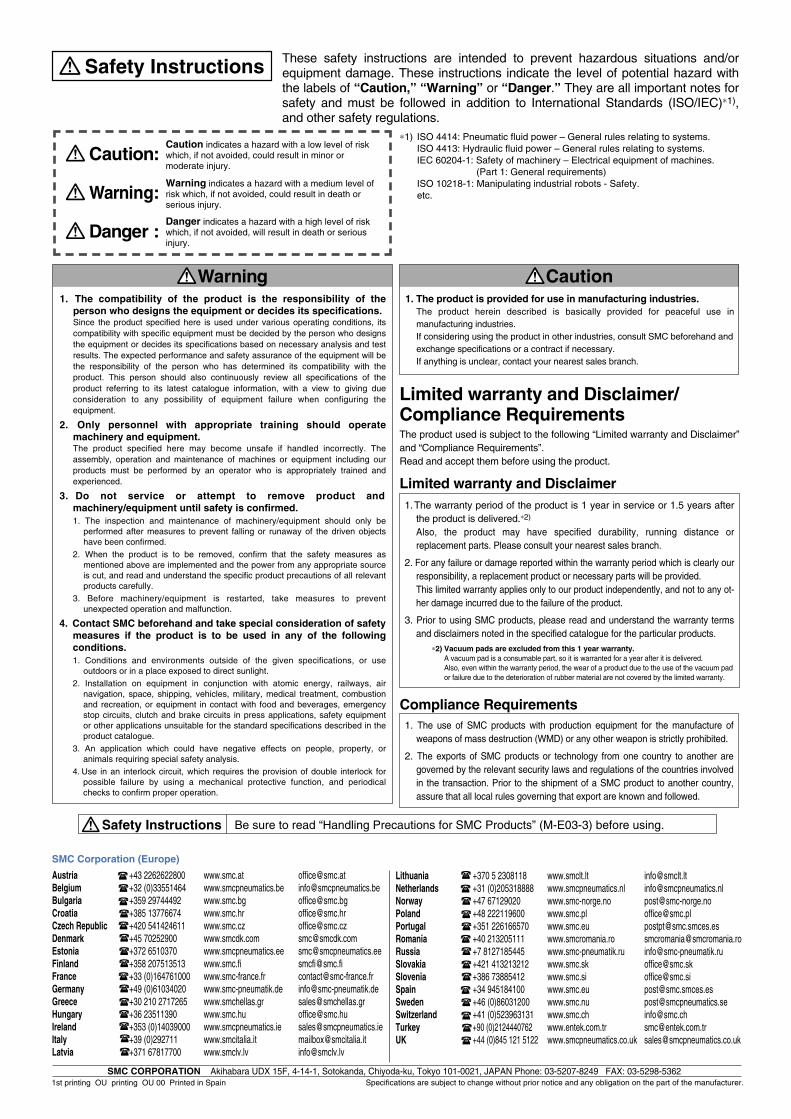
Safety Instructions Be sure to read “Handling Precautions for SMC Products” (M-E03-3) before using.
Lithuania +370 5 2308118 www.smclt.lt [email protected] +31 (0)205318888 www.smcpneumatics.nl [email protected] +47 67129020 www.smc-norge.no [email protected] +48 222119600 www.smc.pl [email protected] +351 226166570 www.smc.eu [email protected] +40 213205111 www.smcromania.ro [email protected] +7 8127185445 www.smc-pneumatik.ru [email protected] +421 413213212 www.smc.sk [email protected] +386 73885412 www.smc.si [email protected] +34 945184100 www.smc.eu [email protected] +46 (0)86031200 www.smc.nu [email protected] +41 (0)523963131 www.smc.ch [email protected] +90 (0)2124440762 www.entek.com.tr [email protected] UK +44 (0)845 121 5122 www.smcpneumatics.co.uk [email protected]
Specifications are subject to change without prior notice and any obligation on the part of the manufacturer.SMC CORPORATION Akihabara UDX 15F, 4-14-1, Sotokanda, Chiyoda-ku, Tokyo 101-0021, JAPAN Phone: 03-5207-8249 FAX: 03-5298-5362
1st printing OU printing OU 00 Printed in Spain
Austria +43 2262622800 www.smc.at [email protected] +32 (0)33551464 www.smcpneumatics.be [email protected] +359 29744492 www.smc.bg [email protected] +385 13776674 www.smc.hr [email protected] Republic +420 541424611 www.smc.cz [email protected] +45 70252900 www.smcdk.com [email protected] Estonia +372 6510370 www.smcpneumatics.ee [email protected] +358 207513513 www.smc.fi [email protected] +33 (0)164761000 www.smc-france.fr [email protected] +49 (0)61034020 www.smc-pneumatik.de [email protected] +30 210 2717265 www.smchellas.gr [email protected] +36 23511390 www.smc.hu [email protected] +353 (0)14039000 www.smcpneumatics.ie [email protected] +39 (0)292711 www.smcitalia.it [email protected] +371 67817700 www.smclv.lv [email protected]
SMC Corporation (Europe)
1. The compatibility of the product is the responsibility of the person who designs the equipment or decides its specifications.Since the product specified here is used under various operating conditions, its compatibility with specific equipment must be decided by the person who designs the equipment or decides its specifications based on necessary analysis and test results. The expected performance and safety assurance of the equipment will be the responsibility of the person who has determined its compatibility with the product. This person should also continuously review all specifications of the product referring to its latest catalogue information, with a view to giving due consideration to any possibility of equipment failure when configuring the equipment.
2. Only personnel with appropriate training should operate machinery and equipment.The product specified here may become unsafe if handled incorrectly. The assembly, operation and maintenance of machines or equipment including our products must be performed by an operator who is appropriately trained and experienced.
3. Do not service or attempt to remove product and machinery/equipment until safety is confirmed.1. The inspection and maintenance of machinery/equipment should only be
performed after measures to prevent falling or runaway of the driven objects have been confirmed.
2. When the product is to be removed, confirm that the safety measures as mentioned above are implemented and the power from any appropriate source is cut, and read and understand the specific product precautions of all relevant products carefully.
3. Before machinery/equipment is restarted, take measures to prevent unexpected operation and malfunction.
4. Contact SMC beforehand and take special consideration of safety measures if the product is to be used in any of the following conditions. 1. Conditions and environments outside of the given specifications, or use
outdoors or in a place exposed to direct sunlight.2. Installation on equipment in conjunction with atomic energy, railways, air
navigation, space, shipping, vehicles, military, medical treatment, combustion and recreation, or equipment in contact with food and beverages, emergency stop circuits, clutch and brake circuits in press applications, safety equipment or other applications unsuitable for the standard specifications described in the product catalogue.
3. An application which could have negative effects on people, property, or animals requiring special safety analysis.
4. Use in an interlock circuit, which requires the provision of double interlock for possible failure by using a mechanical protective function, and periodical checks to confirm proper operation.
Warning
Limited warranty and Disclaimer/Compliance Requirements The product used is subject to the following “Limited warranty and Disclaimer” and “Compliance Requirements”.Read and accept them before using the product.
1. The product is provided for use in manufacturing industries.The product herein described is basically provided for peaceful use in manufacturing industries. If considering using the product in other industries, consult SMC beforehand and exchange specifications or a contract if necessary. If anything is unclear, contact your nearest sales branch.
Caution
Limited warranty and Disclaimer1. The warranty period of the product is 1 year in service or 1.5 years after
the product is delivered.∗2)
Also, the product may have specified durability, running distance or replacement parts. Please consult your nearest sales branch.
2. For any failure or damage reported within the warranty period which is clearly our responsibility, a replacement product or necessary parts will be provided. This limited warranty applies only to our product independently, and not to any ot-her damage incurred due to the failure of the product.
3. Prior to using SMC products, please read and understand the warranty terms and disclaimers noted in the specified catalogue for the particular products.
∗2) Vacuum pads are excluded from this 1 year warranty.A vacuum pad is a consumable part, so it is warranted for a year after it is delivered. Also, even within the warranty period, the wear of a product due to the use of the vacuum pad or failure due to the deterioration of rubber material are not covered by the limited warranty.
Compliance Requirements1. The use of SMC products with production equipment for the manufacture of
weapons of mass destruction (WMD) or any other weapon is strictly prohibited.
2. The exports of SMC products or technology from one country to another are governed by the relevant security laws and regulations of the countries involved in the transaction. Prior to the shipment of a SMC product to another country, assure that all local rules governing that export are known and followed.
These safety instructions are intended to prevent hazardous situations and/or equipment damage. These instructions indicate the level of potential hazard with the labels of “Caution,” “Warning” or “Danger.” They are all important notes for safety and must be followed in addition to International Standards (ISO/IEC)∗1), and other safety regulations.
∗1) ISO 4414: Pneumatic fluid power – General rules relating to systems.ISO 4413: Hydraulic fluid power – General rules relating to systems.IEC 60204-1: Safety of machinery – Electrical equipment of machines.
(Part 1: General requirements)ISO 10218-1: Manipulating industrial robots - Safety.etc.
Caution indicates a hazard with a low level of risk which, if not avoided, could result in minor or moderate injury.
Warning indicates a hazard with a medium level of risk which, if not avoided, could result in death or serious injury.
Caution:
Warning:
Danger :Danger indicates a hazard with a high level of risk which, if not avoided, will result in death or serious injury.
Safety Instructions