Embed Size (px)
Citation preview
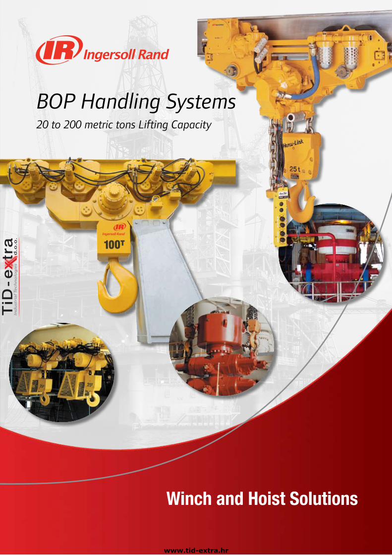
BOP Handling Systems20 to 200 metric tons Lifting Capacity
Winch and Hoist Solutions
www.tid-extra.hr
�
1. BOPHandlingSystems–Overview.......................................................................3
2. BOPHandlingSystems–SelectionChart.............................................. 4
3. Hercu-LinkAirBOPHandlingSystems(20to200tonsCapacity)
. StandardFeaturesandOptions......................................................................... 5
. SpecificationsandPerformanceofPistonMotorDrive................................... 6
. ModelDriver....................................................................................................... 7
. DimensionsandDrawings.......................................................................... 12-13
4. LiftchainBOPHandlingSystems(25to200tonsCapacity)
. StandardFeaturesandOptions......................................................................... 8
. LiftchainAirBOPHandlingSystems
. . SpecificationsandPerformanceofGearMotorDrive.............................. 9
. . ModelDriver............................................................................................ 11.
. . DimensionsandDrawings................................................................. 14-18
. LiftchainHydraulicBOPHandlingSystems
. . SpecificationsandPerformance..............................................................10
. . ModelDriver............................................................................................ 11
. . DimensionsandDrawings................................................................. 14-18
5. EngineeredSolutions
. BHS150MandBHS200Mseries....................................................................... 19
. ULBS100LCA4series(Ultra-lowheadroomdesign)........................................ 19
6. ContactInformation
. WorldwideLocations........................................................................................20
TableofContents
www.tid-extra.hr

Certificate No. FM53539 Certificate No. QUAL/1991/309e
3
Overview
For over 30 years Ingersoll Rand has designed, manufactured, and serviced hundreds of Blowout Preventer Handling Systems for all the
major drilling contractors and oil companies in the industry.
Our familiarity with this complex and critical lifting application enables us to provide the type of equipment, engineering support, and
certifications that these projects require.
The design of our BOP Handling Systems reflects the years of experience we’ve gained by providing equipment for the harshest
environments and applications around the world. Our Oilfield Tough systems feature compact modular designs, robust “bulletproof”
gearboxes, powerful air or hydraulic motors, large diameter load chain, and all steel/cast iron construction which provides increased
safety, rugged reliability, enhanced control, and reduced maintenance.
Our commitment to safety and quality combined with our long experience with difficult lifting applications allows us to provide our clients
with the safest and most cost-effective solutions possible.
TheIngersollRandAdvantage
3rdPartyapprovals by one or more regulatory bodies; the American Bureau of Shipping (ABS), Det Norske Veritas (DNV), Lloyds Register of Shipping (LRS), Norwegian Petroleum Directorate (NPD), European Machinery Directives (CE).
ISO9001certifiedmanufacturingandservicefacilities
5:1designfactorcombinedwithallsteelandcastironconstructionto withstand the brutal environmental and mechanical challenges of the job.
Automaticmulti-discoilbathmotorbrakesthat engage instantly the moment the controls are released.
Highefficiencyplanetarygearboxesthat are fully sealed to exclude contaminants.
Spacesavingmodulardesigns require no deck space, offer low headroom and improved end approach. Ultra-low headroom models are available for applications with severe envelope restrictions.
Airandhydraulicpoweredmodelsto choose from, including high-torque radial piston and compact (lube-free) gear type air motors. Air motors provide built-in overload protection since they will stall without damaging hoist.
Smooth,precise,andsafeloadcontrolwith variable speed pendent control.
Ruggedcorrosionresistantloadchainin 16, 22, and 32 mm sizes has greater elongation and therefore, is more resistant to shock loading. The large links provide for easier external inspection, excellent resistance to abrasion, and will last indefinitely when properly maintained.
Trueverticalliftwhich enhances load control characteristics and safety.
Articulatedtrolleysaccommodate limited side pulling as BOP stack is being lifted.
Engineeredoptions. Rack and pinion trolley drive option for positive traction and improved horizontal load control.
Severe duty packages available for cold weather, marine, and explosion-proof environments including ATEX.
Remote control pendents and consoles.
Spark and corrosion resistant components.
Air and hydraulic festooning systems.
Trolleys for custom fabricated beams.
Clevis and shackle bottom block assemblies.
Low pressure 4 bar (57psi) applications.
BOP.Handling.Systems.OVERVIEW
www.tid-extra.hr
�
SelectionChart
BOP.Handling.Systems.SELECTION CHART
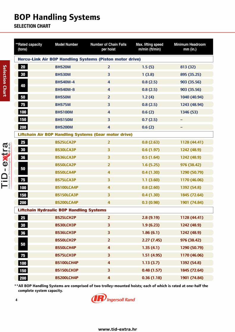
**Ratedcapacity ModelNumber NumberofChainFalls Max.liftingspeed MinimumHeadroom (tons) perhoist m/min(ft/min) mm(in.)
Hercu-Link Air BOP Handling Systems (Piston motor drive)
75
50
30
20
150
100
40
200
. BHS20M 2 1.5(5) 813(32)
BHS30M 3 1(3.8) 895(35.25)
BHS40M-4 4 0.8(2.5) 903(35.56)
BHS40M-8 4 0.8(2.5) 903(35.56)
BHS50M 2 1.2(4) 1040(40.94)
BHS75M 3 0.8(2.5) 1243(48.94)
BHS100M 4 0.6(2) 1346(53)
BHS150M 3 0.7(2.5) –
BHS200M 4 0.6(2) –
BS25LCA2P 2 0.8(2.63) 1128(44.41)
BS30LCA3P 3 0.6(1.97) 1242(48.9)
BS36LCA3P 3 0.5(1.64) 1242(48.9)
BS50LCA2P 2 1.6(5.25) 976(38.42)
BS50LCA4P 4 0.4(1.30) 1290(50.79)
BS75LCA3P 3 1.1(3.60) 1170(46.06)
BS100LCA4P 4 0.8(2.60) 1392(54.8)
BS150LCA3P 3 0.4(1.30) 1845(72.64)
BS200LCA4P 4 0.3(0.98) 1901(74.84)
. BS25LCH2P 2 2.8(9.19) 1128(44.41)
BS30LCH3P 3 1.9(6.23) 1242(48.9)
BS36LCH3P 3 1.86(6.1) 1242(48.9)
BS50LCH2P 2 2.27(7.45) 976(38.42)
BS50LCH4P 4 1.35(4.1) 1290(50.79)
BS75LCH3P 3 1.51(4.95) 1170(46.06)
BS100LCH4P 4 1.13(3.7) 1392(54.8)
BS150LCH3P 3 0.48(1.57) 1845(72.64)
BS200LCH4P 4 0.36(1.18) 1901(74.84)
. . .
Liftchain Air BOP Handling Systems (Gear motor drive)
100
36
75
30
25
150
200
50
Liftchain Hydraulic BOP Handling Systems
100
36
75
30
25
150
200
50
**AllBOPHandlingSystemsarecomprisedoftwotrolley-mountedhoists;eachofwhichisratedatone-halfthecompletesystemcapacity.
www.tid-extra.hr

5
Hercu-LinkAirBOPHandlingSystemsSTANDARD FEATURES AND OPTIONS of Piston Motor Drive – 20 to 200 tons Lifting Capacity
Designed to meet or exceed specifications of one or more of the following regulatory bodies – the Norwegian Petroleum Directorate (NPD), UK HSE, Lloyds Register of Shipping (LRS), Det Norske Veritas (DNV), and American Bureau of Shipping (ABS) for the oilwell drilling industry.
Standard Features
• Radial piston air motor – hoist and trolley• 5:1 design factor• All steel construction• Automatic Fail- Safe, multi disc, motor brake on hoist • Articulated trolley allows limited side pulling operations on
8-wheel trolley models• Fully enclosed planetary gear box• Compact modular design• Corrosion resistant load chain• 9m (30 ft) height of lift standard on all models• Bottom block mounted on bearing with external lubrication point
and water drain• Accu-Trol™ pendent with “emergency stop/start” feature and
9m (30 ft) pendent hose• Limit switch for upper and lower over-travel protection.• Lifting lugs for easy installation• Filter-Lubricator air preparation package mounted on unit• Corrosion resistant Marine 812 finish paint• Galvanized steel chain container• Trolley guide rollers, rubber bumpers, and rail sweeps• Manufacturer test certificate and maintenance manual• Exhaust mufflers
BHS50M (50‑ton system) after storage of Blowout Preventer for periodic maintenance.
Options
• Variable lengths of lift and pendent control hose
• Spark and corrosion resistant (S•COR•E) packages• Rack and pinion trolley drive for positive traction • Clevis and shackle attachment in lieu of bottom hook• Air or hydraulic festooning systems• Trolleys for shipyard fabricated beams• CE compliant models including overload protection and
main emergency stop device• Corrosion resistant Marine 812-X paint system• Sandblast and carbozinc (primer only)• Custom paint coating systems per owners specifications• Custom designed air control consoles• 4 bar (57 psi) application models
BHS100M (100‑ton system) in the process of deploying Blowout Preventer stack
Hercu-LinkA
ir
www.tid-extra.hr
�
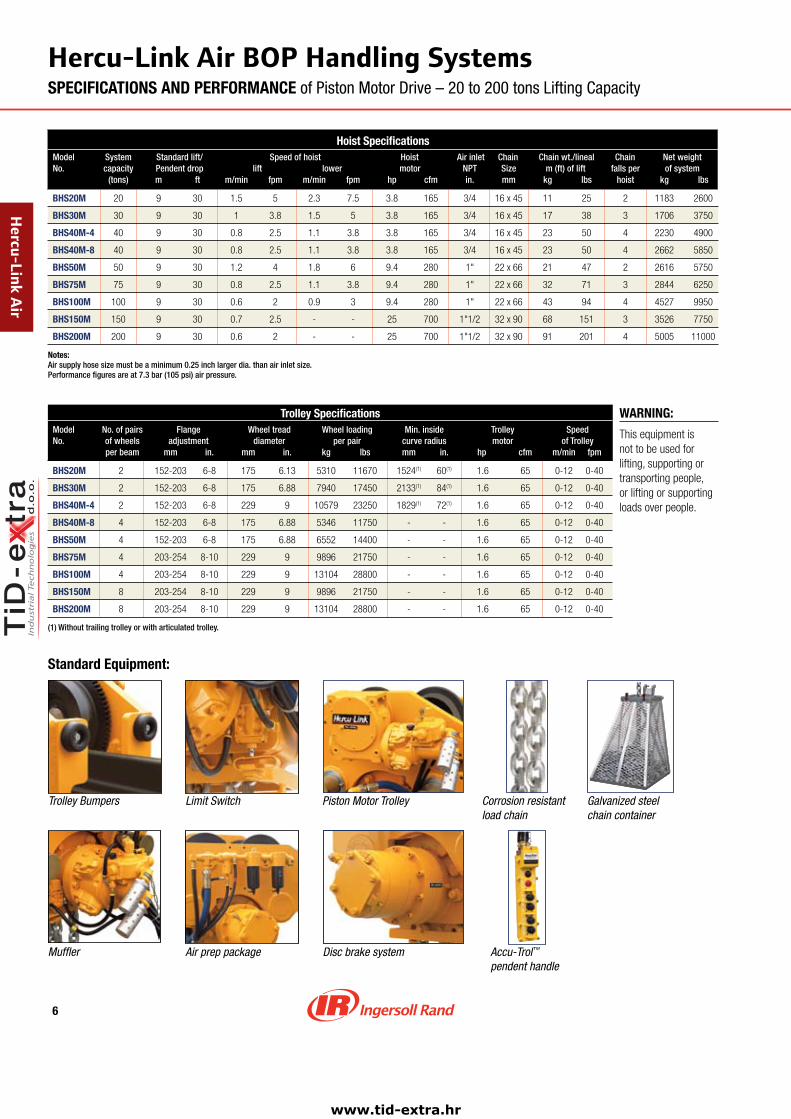
Hercu-LinkAirBOPHandlingSystemsSPECIFICATIONS AND PERFORMANCE of Piston Motor Drive – 20 to 200 tons Lifting Capacity
WARNING:
Thisequipmentisnottobeusedforlifting,supportingortransportingpeople,orliftingorsupportingloadsoverpeople.
Hoist SpecificationsModel System Standard lift/ Speed of hoist Hoist Air inlet Chain Chain wt./lineal Chain Net weightNo. capacity Pendent drop lift lower motor NPT Size m (ft) of lift falls per of system (tons) m ft m/min fpm m/min fpm hp cfm in. mm kg lbs hoist kg lbs
BHS�0M 20 9 30 1.5 5 2.3 7.5 3.8 165 3/4 16x45 11 25 2 1183 2600
BHS30M 30 9 30 1 3.8 1.5 5 3.8 165 3/4 16x45 17 38 3 1706 3750
BHS�0M-� 40 9 30 0.8 2.5 1.1 3.8 3.8 165 3/4 16x45 23 50 4 2230 4900
BHS�0M-8 40 9 30 0.8 2.5 1.1 3.8 3.8 165 3/4 16x45 23 50 4 2662 5850
BHS50M 50 9 30 1.2 4 1.8 6 9.4 280 1" 22x66 21 47 2 2616 5750
BHS75M 75 9 30 0.8 2.5 1.1 3.8 9.4 280 1" 22x66 32 71 3 2844 6250
BHS100M 100 9 30 0.6 2 0.9 3 9.4 280 1" 22x66 43 94 4 4527 9950
BHS150M 150 9 30 0.7 2.5 - - 25 700 1"1/2 32x90 68 151 3 3526 7750
BHS�00M 200 9 30 0.6 2 - - 25 700 1"1/2 32x90 91 201 4 5005 11000
Notes: Air supply hose size must be a minimum 0.25 inch larger dia. than air inlet size. Performance figures are at 7.3 bar (105 psi) air pressure.
Trolley SpecificationsModel No. of pairs Flange Wheel tread Wheel loading Min. inside Trolley SpeedNo. of wheels adjustment diameter per pair curve radius motor of Trolley per beam mm in. mm in. kg lbs mm in. hp cfm m/min fpm
BHS�0M 2 152-203 6-8 175 6.13 5310 11670 1524(1) 60(1) 1.6 65 0-12 0-40
BHS30M 2 152-203 6-8 175 6.88 7940 17450 2133(1) 84(1) 1.6 65 0-12 0-40
BHS�0M-� 2 152-203 6-8 229 9 10579 23250 1829(1) 72(1) 1.6 65 0-12 0-40
BHS�0M-8 4 152-203 6-8 175 6.88 5346 11750 - - 1.6 65 0-12 0-40
BHS50M 4 152-203 6-8 175 6.88 6552 14400 - - 1.6 65 0-12 0-40
BHS75M 4 203-254 8-10 229 9 9896 21750 - - 1.6 65 0-12 0-40
BHS100M 4 203-254 8-10 229 9 13104 28800 - - 1.6 65 0-12 0-40
BHS150M 8 203-254 8-10 229 9 9896 21750 - - 1.6 65 0-12 0-40
BHS�00M 8 203-254 8-10 229 9 13104 28800 - - 1.6 65 0-12 0-40
(1) Without trailing trolley or with articulated trolley.
Hercu-LinkA
ir
Standard Equipment:
Trolley Bumpers
Muffler
Limit Switch
Air prep package
Piston Motor Trolley
Disc brake system Accu‑Trol™ pendent handle
Corrosion resistant load chain
Galvanized steel chain container
www.tid-extra.hr
�
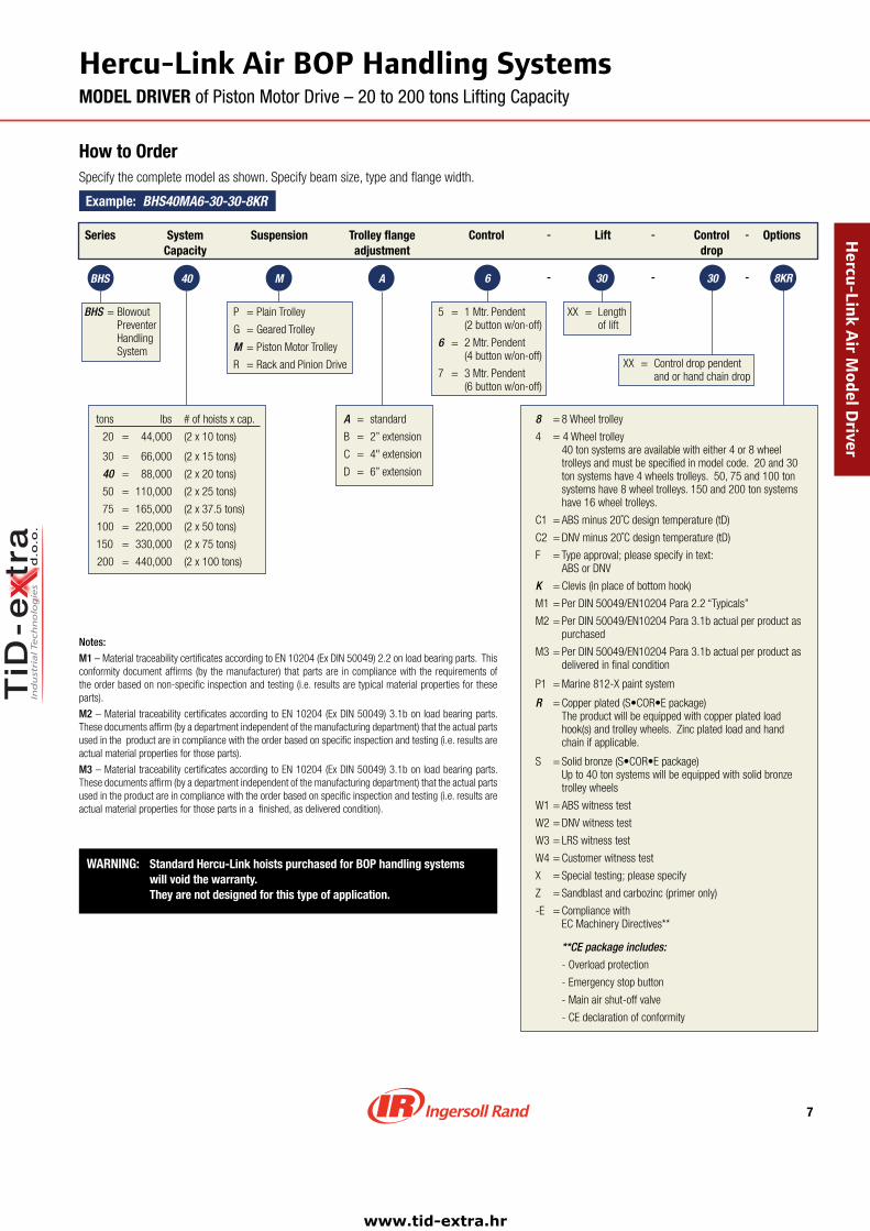
How to OrderSpecify the complete model as shown. Specify beam size, type and flange width.
Example: BHS40MA6-30-30-8KR
BHS = Blowout Preventer Handling System
P = Plain Trolley
G = Geared Trolley
M = Piston Motor Trolley
R = Rack and Pinion Drive
A = standard
B = 2” extension
C = 4" extension
D = 6” extension
5 = 1 Mtr. Pendent (2 button w/on-off)
6 = 2 Mtr. Pendent (4 button w/on-off)
7 = 3 Mtr. Pendent (6 button w/on-off)
XX = Length of lift
Series SystemCapacity
Suspension Trolley flangeadjustment
Control -
-
-
-
Lift
tons lbs # of hoists x cap.
20 = 44,000 (2 x 10 tons)
30 = 66,000 (2 x 15 tons)
40 = 88,000 (2 x 20 tons)
50 = 110,000 (2 x 25 tons)
75 = 165,000 (2 x 37.5 tons)
100 = 220,000 (2 x 50 tons)
150 = 330,000 (2 x 75 tons)
200 = 440,000 (2 x 100 tons)
Notes:
M1 – Material traceability certificates according to EN 10204 (Ex DIN 50049) 2.2 on load bearing parts. This conformity document affirms (by the manufacturer) that parts are in compliance with the requirements of the order based on non-specific inspection and testing (i.e. results are typical material properties for these parts).
M2 – Material traceability certificates according to EN 10204 (Ex DIN 50049) 3.1b on load bearing parts. These documents affirm (by a department independent of the manufacturing department) that the actual parts used in the product are in compliance with the order based on specific inspection and testing (i.e. results are actual material properties for those parts).
M3 – Material traceability certificates according to EN 10204 (Ex DIN 50049) 3.1b on load bearing parts. These documents affirm (by a department independent of the manufacturing department) that the actual parts used in the product are in compliance with the order based on specific inspection and testing (i.e. results are actual material properties for those parts in a finished, as delivered condition).
WARNING: Standard Hercu-Link hoists purchased for BOP handling systems will void the warranty.
They are not designed for this type of application.
8 = 8 Wheel trolley
4 = 4 Wheel trolley 40 ton systems are available with either 4 or 8 wheel trolleys and must be specified in model code. 20 and 30 ton systems have 4 wheels trolleys. 50, 75 and 100 ton systems have 8 wheel trolleys. 150 and 200 ton systems have 16 wheel trolleys.
C1 = ABS minus 20˚C design temperature (tD)
C2 = DNV minus 20˚C design temperature (tD)
F = Type approval; please specify in text: ABS or DNV
K = Clevis (in place of bottom hook)
M1 = Per DIN 50049/EN10204 Para 2.2 “Typicals”
M2 = Per DIN 50049/EN10204 Para 3.1b actual per product as purchased
M3 = Per DIN 50049/EN10204 Para 3.1b actual per product as delivered in final condition
P1 = Marine 812-X paint system
R = Copper plated (S•COR•E package) The product will be equipped with copper plated load hook(s) and trolley wheels. Zinc plated load and hand chain if applicable.
S = Solid bronze (S•COR•E package) Up to 40 ton systems will be equipped with solid bronze trolley wheels
W1 = ABS witness test
W2 = DNV witness test
W3 = LRS witness test
W4 = Customer witness test
X = Special testing; please specify
Z = Sandblast and carbozinc (primer only)
-E = Compliance with EC Machinery Directives**
**CE package includes:
- Overload protection
- Emergency stop button
- Main air shut-off valve
- CE declaration of conformity
Options
XX = Control drop pendent and or hand chain drop
Controldrop
-
- 8KR30306AM40BHS
Hercu-Link Air BOP Handling SystemsMODEL DRIVER of Piston Motor Drive – 20 to 200 tons Lifting Capacity
Hercu-Link A
ir Model D
river
www.tid-extra.hr
8
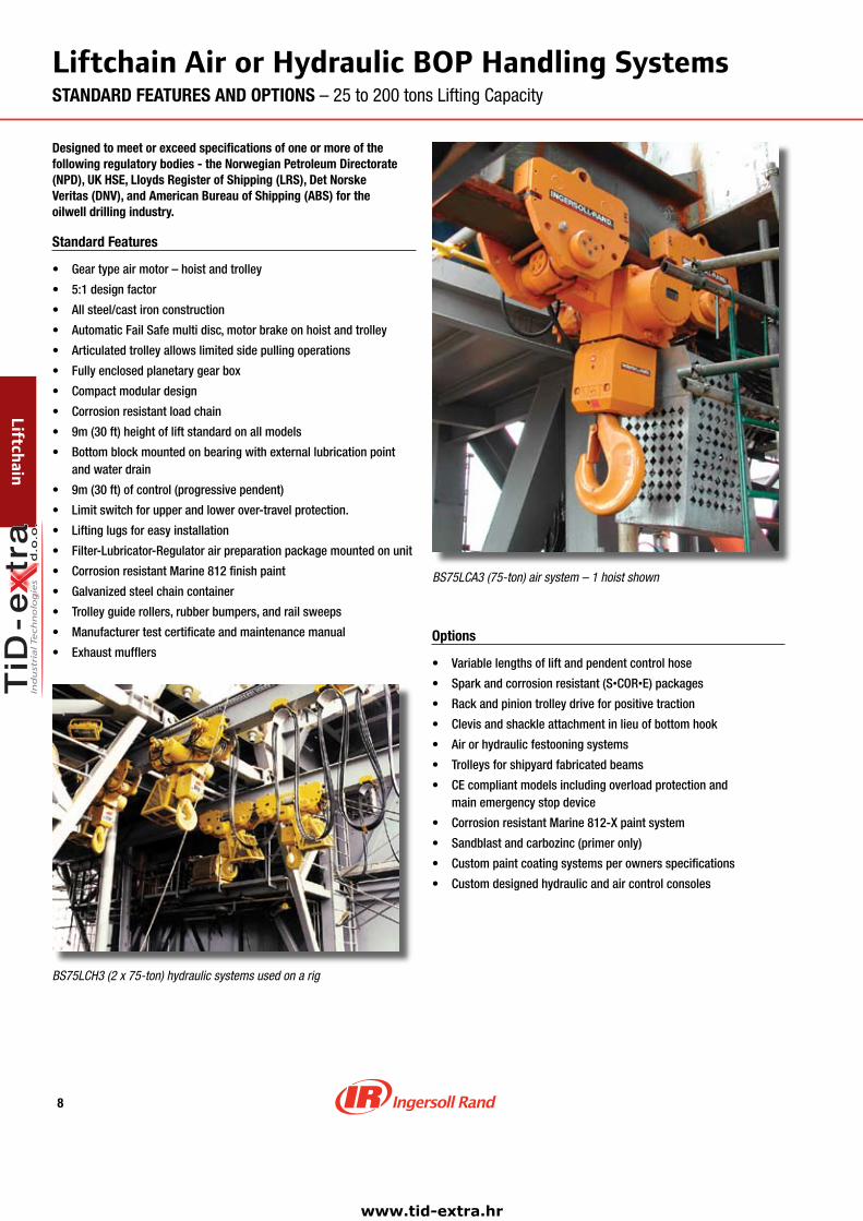
LiftchainAirorHydraulicBOPHandlingSystemsSTANDARD FEATURES AND OPTIONS – 25 to 200 tons Lifting Capacity
Designed to meet or exceed specifications of one or more of the following regulatory bodies - the Norwegian Petroleum Directorate (NPD), UK HSE, Lloyds Register of Shipping (LRS), Det Norske Veritas (DNV), and American Bureau of Shipping (ABS) for the oilwell drilling industry.
Standard Features
• Gear type air motor – hoist and trolley
• 5:1 design factor
• All steel/cast iron construction
• Automatic Fail Safe multi disc, motor brake on hoist and trolley
• Articulated trolley allows limited side pulling operations
• Fully enclosed planetary gear box
• Compact modular design
• Corrosion resistant load chain
• 9m (30 ft) height of lift standard on all models
• Bottom block mounted on bearing with external lubrication point and water drain
• 9m (30 ft) of control (progressive pendent)
• Limit switch for upper and lower over-travel protection.
• Lifting lugs for easy installation
• Filter-Lubricator-Regulator air preparation package mounted on unit
• Corrosion resistant Marine 812 finish paint
• Galvanized steel chain container
• Trolley guide rollers, rubber bumpers, and rail sweeps
• Manufacturer test certificate and maintenance manual
• Exhaust mufflersOptions
• Variable lengths of lift and pendent control hose
• Spark and corrosion resistant (S•COR•E) packages
• Rack and pinion trolley drive for positive traction
• Clevis and shackle attachment in lieu of bottom hook
• Air or hydraulic festooning systems
• Trolleys for shipyard fabricated beams
• CE compliant models including overload protection and main emergency stop device
• Corrosion resistant Marine 812-X paint system
• Sandblast and carbozinc (primer only)
• Custom paint coating systems per owners specifications
• Custom designed hydraulic and air control consoles
BS75LCH3 (2 x 75‑ton) hydraulic systems used on a rig
BS75LCA3 (75‑ton) air system – 1 hoist shown
Liftchain
www.tid-extra.hr

9
LiftchainAirBOPHandlingSystemsSPECIFICATIONS AND PERFORMANCE of Gear Motor Drive – 25 to 200 tons Lifting Capacity
Hoist SpecificationsModel System Standard lift/ Speed of hoist Hoist Air inlet Chain Chain wt./lineal Chain Net weightNo. capacity Pendent drop lift lower motor BSP Size m (ft) of lift falls per of system (tons) m ft m/min fpm m/min fpm hp cfm in. mm kg lbs hoist kg lbs
BS�5LCA�P 25 9 30 0.8 2.63 1.50 4.92 4 163 3/4 16x45 11 25 2 800 1760
BS30LCA3P 30 9 30 0.6 1.97 1.00 3.28 4 163 3/4 16x45 17 38 3 970 2134
BS3�LCA3P 36 9 30 0.5 1.64 1.00 3.28 4 163 3/4 16x45 17 38 3 970 2134
BS50LCA�P 50 9 30 1.6 5.25 2.50 8.20 10 406 1"1/4 22x66 21 47 2 1130 2486
BS50LCA�P 50 9 30 0.4 1.30 0.75 2.46 4 163 3/4 16x45 23 50 4 1040 2288
BS75LCA3P 75 9 30 1.1 3.60 1.70 5.58 10 406 1"1/4 22x66 32 71 3 4000 8800
BS100LCA�P 100 9 30 0.8 2.60 0.90 2.95 10 406 1"1/4 22x66 43 94 4 4400 9680
BS150LCA3P 150 9 30 0.4 1.30 0.48 1.57 10 406 1"1/4 32x90 68 151 3 9440 20768
BS�00LCA�P 200 9 30 0.3 0.98 0.35 1.16 10 406 1"1/4 32x90 91 201 4 9990 21978
Notes: Air supply hose size must be a minimum 0.25 inch larger dia. than air inlet size.
LiftchainAir
Trolley SpecificationsModel No. of pairs Flange Wheel tread Wheel loading Min. inside Trolley SpeedNo. of wheels adjustment diameter per pair curve radius motor of Trolley per beam mm in. mm in. kg lbs mm in. hp cfm m/min fpm
BS�5LCA�P 2 131-310 5-12 160 6.30 6250 13750 3 118 2 81 12 39
BS30LCA3P 2 131-310 5-12 225 8.86 7500 16500 5 197 2 81 12 39
BS3�LCA3P 2 131-310 5-12 225 8.86 9000 19800 5 197 2 81 12 39
BS50LCA�P 4 160-310 6-12 160 6.30 6250 13750 105 4134 2(Qty2) 81(Qty2) 12 39
BS50LCA�P 2 131-310 5-12 225 8.86 12500 27500 5 197 2 81 12 39
BS75LCA3P 4 160-310 6-12 225 8.86 9375 20625 105 4134 2(Qty2) 81(Qty2) 12 39
BS100LCA�P 4 160-310 6-12 225 8.86 12500 27500 105 4134 2(Qty2) 81(Qty2) 12 39
BS150LCA3P 8 160-310 6-12 225 8.86 9375 20625 130 5118 2(Qty4) 81(Qty4) 12 39
BS�00LCA�P 8 160-310 6-12 225 8.86 12500 27500 130 5118 2(Qty4) 81(Qty4) 12 39
WARNING:
Thisequipmentisnottobeusedforlifting,supportingortransportingpeople,orliftingorsupportingloadsoverpeople.
Liftchain 200‑ton BOP Handling System(1 hoist shown)
www.tid-extra.hr
10
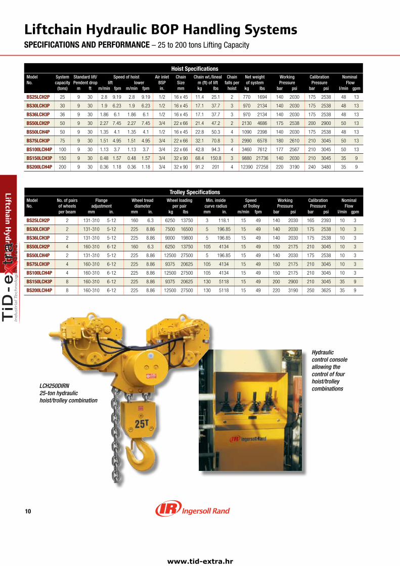
LiftchainHydraulicBOPHandlingSystemsSPECIFICATIONS AND PERFORMANCE – 25 to 200 tons Lifting Capacity
Trolley SpecificationsModel No. of pairs Flange Wheel tread Wheel loading Min. inside Speed Working Calibration NominalNo. of wheels adjustment diameter per pair curve radius of Trolley Pressure Pressure Flow per beam mm in. mm in. kg lbs mm in. m/min fpm bar psi bar psi l/min gpm
BS�5LCH�P 2 131-310 5-12 160 6.3 6250 13750 3 118.1 15 49 140 2030 165 2393 10 3
BS30LCH3P 2 131-310 5-12 225 8.86 7500 16500 5 196.85 15 49 140 2030 175 2538 10 3
BS3�LCH3P 2 131-310 5-12 225 8.86 9000 19800 5 196.85 15 49 140 2030 175 2538 10 3
BS50LCH�P 4 160-310 6-12 160 6.3 6250 13750 105 4134 15 49 150 2175 210 3045 10 3
BS50LCH�P 2 131-310 5-12 225 8.86 12500 27500 5 196.85 15 49 140 2030 175 2538 10 3
BS75LCH3P 4 160-310 6-12 225 8.86 9375 20625 105 4134 15 49 150 2175 210 3045 10 3
BS100LCH�P 4 160-310 6-12 225 8.86 12500 27500 105 4134 15 49 150 2175 210 3045 10 3
BS150LCH3P 8 160-310 6-12 225 8.86 9375 20625 130 5118 15 49 200 2900 210 3045 35 9
BS�00LCH�P 8 160-310 6-12 225 8.86 12500 27500 130 5118 15 49 220 3190 250 3625 35 9
LiftchainHydraulic
LCH250DIRN25-tonhydraulichoist/trolleycombination
Hydrauliccontrolconsoleallowingthecontroloffourhoist/trolleycombinations
Hoist SpecificationsModel System Standard lift/ Speed of hoist Air inlet Chain Chain wt./lineal Chain Net weight Working Calibration NominalNo. capacity Pendent drop lift lower BSP Size m (ft) of lift falls per of system Pressure Pressure Flow (tons) m ft m/min fpm m/min fpm in. mm kg lbs hoist kg lbs bar psi bar psi l/min gpm
BS�5LCH�P 25 9 30 2.8 9.19 2.8 9.19 1/2 16x45 11.4 25.1 2 770 1694 140 2030 175 2538 48 13
BS30LCH3P 30 9 30 1.9 6.23 1.9 6.23 1/2 16x45 17.1 37.7 3 970 2134 140 2030 175 2538 48 13
BS3�LCH3P 36 9 30 1.86 6.1 1.86 6.1 1/2 16x45 17.1 37.7 3 970 2134 140 2030 175 2538 48 13
BS50LCH�P 50 9 30 2.27 7.45 2.27 7.45 3/4 22x66 21.4 47.2 2 2130 4686 175 2538 200 2900 50 13
BS50LCH�P 50 9 30 1.35 4.1 1.35 4.1 1/2 16x45 22.8 50.3 4 1090 2398 140 2030 175 2538 48 13
BS75LCH3P 75 9 30 1.51 4.95 1.51 4.95 3/4 22x66 32.1 70.8 3 2990 6578 180 2610 210 3045 50 13
BS100LCH�P 100 9 30 1.13 3.7 1.13 3.7 3/4 22x66 42.8 94.3 4 3460 7612 177 2567 210 3045 50 13
BS150LCH3P 150 9 30 0.48 1.57 0.48 1.57 3/4 32x90 68.4 150.8 3 9880 21736 140 2030 210 3045 35 9
BS�00LCH�P 200 9 30 0.36 1.18 0.36 1.18 3/4 32x90 91.2 201 4 12390 27258 220 3190 240 3480 35 9
www.tid-extra.hr
11
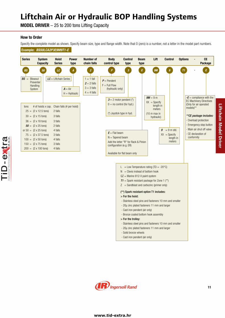
LiftchainAirorHydraulicBOPHandlingSystemsMODEL DRIVER – 25 to 200 tons Lifting Capacity
How to Order
Specifythecompletemodelasshown.Specifybeamsize,typeandflangewidth.Notethat0(zero)isanumber,notaletterinthemodelpartnumbers.
Example: BS50LCA2P3E9M9T1-E
Series Hoist Series
Power type
Beam type
-
-BS LC
Lift Control Options CE Package
E50 A
A=Air
H=Hydraulic
Number of chain falls
1=1fall
2=2falls
3=3falls
4=4falls
LC=LiftchainSeries
3
E=Flatbeam
N=Taperedbeam
Addtheletter"R"forRack&Pinionconfiguration(e.g.ER)
Availableforflatbeamonly
9 =9mstd.
XX =Specifylengthinmeters
3=2motorpendent(*)
0=nocontrol(forhyd.)
(*)Joysticktypeinhyd.
9M=9m
XX=Specifylengthinmeters
(10mmaxinhydraulic)
-E=compliancewiththeECMachineryDirectives(Onlyforairoperatedmodels)**
**CEpackageincludes:
-Overloadprotection
-Emergencystopbutton
-Mainairshutoffvalve
-CEdeclarationofconformity
BS= Blowout Preventer Handling System
SystemCapacity
tons #ofhoistsxcap. Chainfalls(#perhoist)
25 =(2x12.5tons) 2falls
30 =(2x15tons) 3falls
36 =(2x18tons) 3falls
50 =(2x25tons) 2falls
or50 =(2x25tons) 4falls
75 =(2x37.5tons) 3falls
100 =(2x50tons) 4falls
150 =(2x75tons) 3falls
200 =(2x100tons) 4falls
Body control type
P=Pendent
F=FullFlow(hydrauliconly)
Controltype
L=LowTemperaturerating(TD=-20°C)
N=Clevisinsteadofbottomhook
QZ=Marine812-Xpaintsystem
T1=SparkresistantpackageforZone1(**)
Z =Sandblastandcarbozinc(primeronly)
(**) Spark resistant option T1 includes:
> For the hoist:
-Stainlesssteelpinsandfasteners10mmandsmaller
-20µzincplatedfasteners11mmandlarger
-Castironpendent(aironly)
-Bronzecoatedbottomhookassembly
> For the trolley:
-Stainlesssteelpinsandfasteners10mmandsmaller
-20µzincplatedfasteners11mmandlarger
-Solidbronzewheels
-Castironpendent(aironly)
T19M 9EP2
LiftchainModelD
river
www.tid-extra.hr
1�
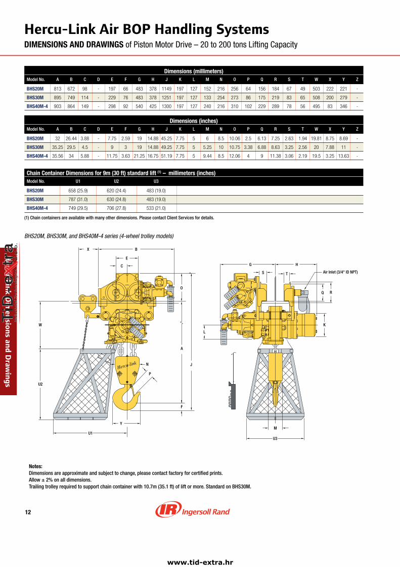
Hercu-LinkAirBOPHandlingSystemsDIMENSIONS AND DRAWINGS of Piston Motor Drive – 20 to 200 tons Lifting Capacity
Dimensions (millimeters)Model No. A B C D E F G H J K L M N O P Q R S T W X Y Z
BHS�0M 813 672 98 - 197 66 483 378 1149 197 127 152 216 256 64 156 184 67 49 503 222 221 -
BHS30M 895 749 114 - 229 76 483 378 1251 197 127 133 254 273 86 175 219 83 65 508 200 279 -
BHS�0M-� 903 864 149 - 298 92 540 425 1300 197 127 240 216 310 102 229 289 78 56 495 83 346 -
Dimensions (inches)Model No. A B C D E F G H J K L M N O P Q R S T W X Y Z
BHS�0M 32 26.44 3.88 - 7.75 2.59 19 14.88 45.25 7.75 5 6 8.5 10.06 2.5 6.13 7.25 2.63 1.94 19.81 8.75 8.69 -
BHS30M 35.25 29.5 4.5 - 9 3 19 14.88 49.25 7.75 5 5.25 10 10.75 3.38 6.88 8.63 3.25 2.56 20 7.88 11 -
BHS�0M-� 35.56 34 5.88 - 11.75 3.63 21.25 16.75 51.19 7.75 5 9.44 8.5 12.06 4 9 11.38 3.06 2.19 19.5 3.25 13.63 -
N
P
F
Y
A
J
W
X B
E
C
O
L
M
Q
Air Inlet (3/4" ID NPT)
G H
TS
R
K
U1
U2
U3
BHS20M, BHS30M, and BHS40M‑4 series (4‑wheel trolley models)
Notes: Dimensions are approximate and subject to change, please contact factory for certified prints. Allow ± 2% on all dimensions. Trailing trolley required to support chain container with 10.7m (35.1 ft) of lift or more. Standard on BHS30M.
Hercu-LinkD
imensionsandD
rawings
Chain Container Dimensions for 9m (30 ft) standard lift (1) – millimeters (inches)Model No. U1 U2 U3
BHS�0M 658(25.9) 620(24.4) 483(19.0)
BHS30M 787(31.0) 630(24.8) 483(19.0)
BHS�0M-� 749(29.5) 706(27.8) 533(21.0)
(1) Chain containers are available with many other dimensions. Please contact Client Services for details.
www.tid-extra.hr
13
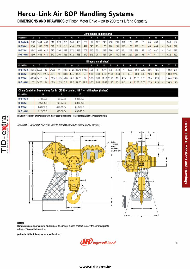
Dimensions (millimeters)Model No. A B C D E F G H J K L M N O P Q R S T W X Y Z
BHS�0M-8 903 1454 406 616 229 92 540 425 1286 197 127 240 216 291 102 175 219 81 65 438 - 346 584
BHS50M 1040 1568 578 616 229 92 495 362 1422 245 251 175 286 291 102 175 219 81 65 484 - 346 699
BHS75M 1243 1648 610 673 298 129 572 438 1702 245 251 283 286 330 121 229 289 78 57 487 - 392 622
BHS100M 1346 1648 610 673 298 165 572 438 1842 245 251 321 286 330 165 229 289 78 57 487 - 622 622
Dimensions (inches)Model No. A B C D E F G H J K L M N O P Q R S T W X Y Z
BHS�0M-8 35.56 57.25 16 24.25 9 3.63 21.25 16.75 50.63 7.75 5 9.44 8.5 11.44 4 6.88 8.63 3.19 2.56 17.25 - 13.63 23
BHS50M 40.94 61.75 22.75 24.25 9 3.63 19.5 14.25 56 9.63 9.88 6.88 11.25 11.44 4 6.88 8.63 3.19 2.56 19.06 - 13.63 27.5
BHS75M 48.94 64.88 24 26.5 11.75 5.06 22.5 17.25 67 9.63 9.88 11.13 11.25 13 4.75 9 11.38 3.06 2.25 19.19 - 15.44 24.5
BHS100M 53 64.88 24 26.5 11.75 6.5 22.5 17.25 72.5 9.63 9.88 12.63 11.25 13 6.5 9 11.38 3.06 2.25 19.19 - 20.63 24.5
G HS
T
Q R
K
L
M
A
F
B
C D
EZ
O
W
J
N
P
Y
Air Inlet(1" ID NPT, exceptBHS40M-8 is 3/4" ID NPT)
U1
U2
U3
*
BHS40M‑8, BHS50M, BHS75M, and BHS100M series (8‑wheel trolley models)
Hercu-LinkAirBOPHandlingSystemsDIMENSIONS AND DRAWINGS of Piston Motor Drive – 20 to 200 tons Lifting Capacity
Notes: Dimensions are approximate and subject to change, please contact factory for certified prints. Allow ± 2% on all dimensions.
(*) Contact Client Services for specifications.
Hercu-LinkD
imensionsandD
rawings
Chain Container Dimensions for 9m (30 ft) standard lift (1) – millimeters (inches)Model No. U1 U2 U3
BHS�0M-8 749(29.5) 706(27.8) 533(21.0)
BHS50M 795(31.3) 706(27.8) 533(21.0)
BHS75M 886(34.9) 859(33.8) 610(24.0)
BHS100M 922(36.3) 935(36.8) 635(25.0)
(1) Chain containers are available with many other dimensions. Please contact Client Services for details.
www.tid-extra.hr

1�
LiftchainAirandHydraulicBOPHandlingSystemsDIMENSIONS AND DRAWINGS – 25 to 200 tons Lifting Capacity
Dimensions (millimeters)Model No. A B C D E F G H I J K L M
LCA Air Series
BS�5LCA�P 1128 500 120 - 240 67 318 253 338 1415 228 85 150
BS30LCA3P 1242 642 156 - 312 80 377 311 342 1592 228 85 200
BS3�LCA3P 1242 642 156 - 312 80 377 311 342 1592 228 85 200
BS50LCA�P 1290 642 156 - 312 94 377 311 342 1606 228 85 200
LCH Hydraulic Series
BS�5LCH�P 1128 500 120 - 240 67 318 253 357 1415 228 143 150
BS30LCH3P 1242 642 156 - 312 80 377 311 360 1592 228 143 200
BS3�LCH3P 1242 642 156 - 312 80 377 311 360 1592 228 143 200
BS50LCH�P 1290 642 156 - 312 94 377 311 360 1606 228 143 200
Dimensions (millimeters)Model No. N O P Q R S T U V W X Y Z
LCA Air Series
BS�5LCA�P 203 220 58 160 200 48 68 - 58 739 - 222 -
BS30LCA3P 206 270 78 225 272 56 80 - 58 797 - 283 -
BS3�LCA3P 206 270 78 225 272 56 80 - 58 797 - 283 -
BS50LCA�P 235 270 87 225 272 56 80 - 58 797 - 339 -
LCH Hydraulic Series
BS� 5LCH�P 203 220 58 160 200 48 68 - 58 739 - 222 -
BS30LCH3P 206 270 78 225 272 56 80 - 58 797 - 283 -
BS3�LCH3P 206 270 78 225 272 56 80 - 58 797 - 283 -
BS50LCH�P 235 270 87 225 272 56 80 - 58 797 - 339 -
Dimensions (inches)Model No. A B C D E F G H I J K L M
LCA Air Series
BS�5LCA�P 44.41 19.68 4.72 - 9.45 2.64 12.52 9.96 13.3 55.7 8.98 3.35 5.9
BS30LCA3P 48.9 25.27 6.14 - 12.28 3.15 14.84 12.24 13.46 62.68 8.98 3.35 7.87
BS3�LCA3P 48.9 25.27 6.14 - 12.28 3.15 14.84 12.24 13.46 62.68 8.98 3.35 7.87
BS50LCA�P 50.79 25.27 6.14 - 12.28 3.7 14.84 12.24 13.46 63.23 8.98 3.35 7.87
LCH Hydraulic Series
BS�5LCH�P 44.41 19.68 4.72 - 9.45 2.64 12.52 9.96 14.05 55.7 8.98 5.63 5.9
BS30LCH3P 48.9 25.27 6.14 - 12.28 3.15 14.84 12.24 14.17 62.68 8.98 5.63 7.87
BS3�LCH3P 48.9 25.27 6.14 - 12.28 3.15 14.84 12.24 14.17 62.68 8.98 5.63 7.87
BS50LCH�P 50.79 25.27 6.14 - 12.28 3.7 14.84 12.24 14.17 63.23 8.98 5.63 7.87
Dimensions (inches)Model No. N O P Q R S T U V W X Y Z
LCA Air Series
BS�5LCA�P 7.99 8.66 2.28 6.3 7.87 1.89 2.68 - 2.28 29.09 - 8.74 -
BS30LCA3P 8.11 10.63 3.07 8.86 10.71 2.2 3.15 - 2.28 31.38 - 11.14 -
BS3�LCA3P 8.11 10.63 3.07 8.86 10.71 2.2 3.15 - 2.28 31.38 - 11.14 -
BS50LCA�P 9.25 10.63 3.42 8.86 10.71 2.2 3.15 - 2.28 31.38 - 13.35 -
LCH Hydraulic Series
BS�5LCH�P 7.99 8.66 2.28 6.3 7.87 1.89 2.68 - 2.28 29.09 - 8.74 -
BS30LCH3P 8.11 10.63 3.07 8.86 10.71 2.2 3.15 - 2.28 31.38 - 11.14 -
BS3�LCH3P 8.11 10.63 3.07 8.86 10.71 2.2 3.15 - 2.28 31.38 - 11.14 -
BS50LCH�P 9.25 10.63 3.42 8.86 10.71 2.2 3.15 - 2.28 31.38 - 13.35 -
LiftchainDimensionsandD
rawings
www.tid-extra.hr
15
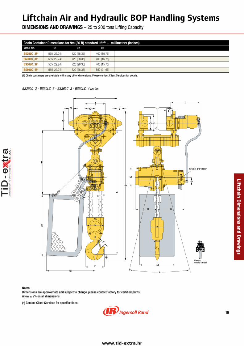
LiftchainAirandHydraulicBOPHandlingSystemsDIMENSIONS AND DRAWINGS – 25 to 200 tons Lifting Capacity
BS25LC_2 ‑ BS30LC_3 ‑ BS36LC_3 ‑ BS50LC_4 series
Chain Container Dimensions for 9m (30 ft) standard lift (1) – millimeters (inches)Model No. U1 U2 U3
BS�5LC_�P 565(22.24) 720(28.35) 400(15.75)
BS30LC_3P 565(22.24) 720(28.35) 400(15.75)
BS3�LC_3P 565(22.24) 720(28.35) 400(15.75)
BS50LC_�P 565(22.24) 720(28.35) 550(21.65)
(1) Chain containers are available with many other dimensions. Please contact Client Services for details.
V V
N
H
A
G
P
Q R
L
TS
F
Y
J
U1
U2W
C
E
B
O
U3
K
I
M
*
4 leversremote control
OST P
Air inlet 3/4" ID BSP
Notes: Dimensions are approximate and subject to change, please contact factory for certified prints. Allow ± 2% on all dimensions.
(*) Contact Client Services for specifications.
LiftchainDimensionsandD
rawings
www.tid-extra.hr

1�
LiftchainAirandHydraulicBOPHandlingSystemsDIMENSIONS AND DRAWINGS – 25 to 200 tons Lifting Capacity
Dimensions (millimeters)Model No. A B C D E F G H I J K L M
Liftchain Air Series
BS50LCA�P 976 1240 370 500 240 97 492 367 342 1293 223 196 190
BS75LCA3P 1170 1552 455 642 312 132 547 472 360 1572 223 196 278
BS100LCA�P 1392 1552 455 642 312 152 547 472 360 1662 223 196 281
Liftchain Hydraulic Series
BS50LCH�P 976 1240 370 500 240 97 446 265 357 1293 298 137 190
BS75LCH3P 1170 1552 455 642 312 132 500 372 360 1572 298 137 278
BS100LCH�P 1392 1552 455 642 312 152 500 372 360 1662 298 137 281
Dimensions (millimeters)Model No. N O P Q R S T U V W X Y Z
Liftchain Air Series
BS50LCA�P 276 220 82 160 200 48 68 - 58 436 - 339 500
BS75LCA3P 298 270 103 225 272 56 80 - 58 494 - 384 598
BS100LCA�P 352 270 118 225 272 56 80 - 58 494 - 384 598
Liftchain Hydraulic Series
BS50LCH�P 276 220 82 160 200 48 68 - 58 436 - 339 500
BS75LCH3P 298 270 103 225 272 56 80 - 58 494 - 384 598
BS100LCH�P 352 270 118 225 272 56 80 - 58 494 - 384 598
Dimensions (inches)Model No. A B C D E F G H I J K L M
Liftchain Air Series
BS50LCA�P 38.42 48.82 14.57 19.68 9.45 3.82 19.37 14.45 13.46 50.9 8.78 7.72 7.48
BS75LCA3P 46.06 61.1 17.91 25.28 12.28 5.2 21.5 18.58 14.17 61.89 8.78 7.72 10.94
BS100LCA�P 54.8 61.1 17.91 25.28 12.28 5.98 21.5 18.58 14.17 65.43 8.78 7.72 11.06
Liftchain Hydraulic Series
BS50LCH�P 38.42 48.82 14.57 19.68 9.45 3.82 17.56 10.43 14.05 50.9 11.73 5.39 7.48
BS75LCH3P 46.06 61.1 17.91 25.28 12.28 5.2 19.68 14.64 14.17 61.89 11.73 5.39 10.94
BS100LCH�P 54.8 61.1 17.91 25.28 12.28 5.98 19.68 14.64 14.17 65.43 11.73 5.39 11.06
Dimensions (inches)Model No. N O P Q R S T U V W X Y Z
Liftchain Air Series
BS50LCA�P 10.87 8.66 3.23 6.3 7.87 1.89 2.68 - 2.28 17.16 - 13.35 19.68
BS75LCA3P 11.73 10.63 4.05 8.86 10.71 2.2 3.15 - 2.28 19.45 - 15.12 23.54
BS100LCA�P 11.73 10.63 4.65 8.86 10.71 2.2 3.15 - 2.28 19.45 - 15.12 23.54
Liftchain Hydraulic Series
BS50LCH�P 10.87 8.66 3.23 6.3 7.87 1.89 2.68 - 2.28 17.16 - 13.35 19.68
BS75LCH3P 11.73 10.63 4.05 8.86 10.71 2.2 3.15 - 2.28 19.45 - 15.12 23.54
BS100LCH�P 11.73 10.63 4.65 8.86 10.71 2.2 3.15 - 2.28 19.45 - 15.12 23.54
LiftchainDimensionsandD
rawings
www.tid-extra.hr
17
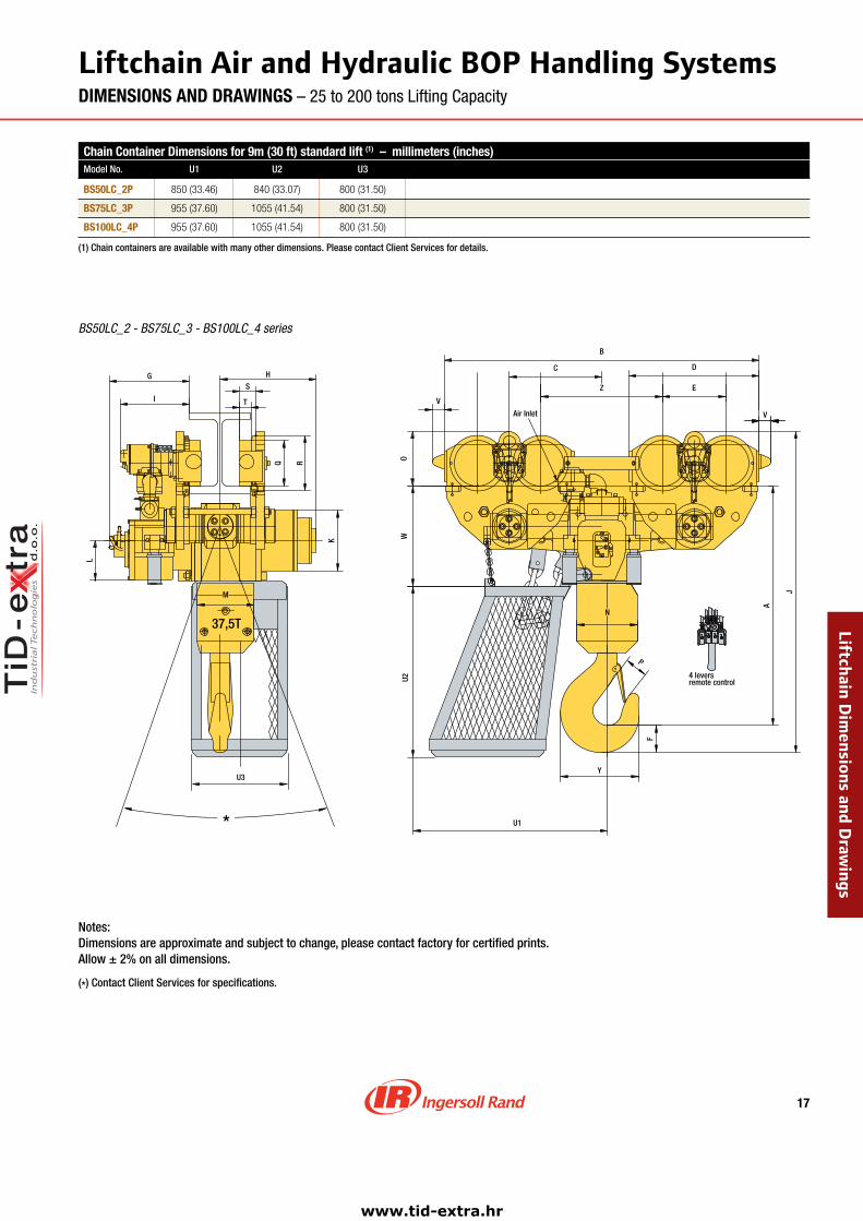
LiftchainAirandHydraulicBOPHandlingSystemsDIMENSIONS AND DRAWINGS – 25 to 200 tons Lifting Capacity
BS50LC_2 ‑ BS75LC_3 ‑ BS100LC_4 series
U3
U1
37,5T
M
H
F
P
A
V
Y
T
S
Q R
L
J
I
G
K
U2
*
N
Z E
V
B
C D
OW
remote control4 levers
PTS O
Air Inlet
Chain Container Dimensions for 9m (30 ft) standard lift (1) – millimeters (inches)Model No. U1 U2 U3
BS50LC_�P 850(33.46) 840(33.07) 800(31.50)
BS75LC_3P 955(37.60) 1055(41.54) 800(31.50)
BS100LC_�P 955(37.60) 1055(41.54) 800(31.50)
(1) Chain containers are available with many other dimensions. Please contact Client Services for details.
Notes:Dimensions are approximate and subject to change, please contact factory for certified prints.Allow ± 2% on all dimensions.
(*) Contact Client Services for specifications.
LiftchainDimensionsandD
rawings
www.tid-extra.hr

18
LiftchainAirandHydraulicBOPHandlingSystemsDIMENSIONS AND DRAWINGS – 25 to 200 tons Lifting Capacity
Chain Container Dimensions for 9m (30 ft) standard lift (1) – millimeters (inches)Model No. U1 U2 U3
BS150LC_3P 1200(47.24) 1200(47.24) 920(36.22)
BS�00LC_�P 1200(47.24) 1200(47.24) 920(36.22)
(1) Chain containers are available with many other dimensions. Please contact Client Services for details.
Dimensions – millimeters (inches)Model No. A B C D E F G H I J K L M
Liftchain Air Series
BS150LCA3P 1845(73) 3254(128) 906(36) 642(25) 312(12) 190(7) 714(28) 714(28) 360(14) 2305(91) 298(12) 196(8) 490(19)
BS�00LCA�P 1901(75) 3254(128) 906(36) 642(25) 312(12) 212(8) 714(28) 714(28) 360(14) 2383(94) 298(12) 196(8) 430(17)
Liftchain Hydraulic Series
BS150LCH3P 1845(73) 3254(128) 906(36) 642(25) 312(12) 190(7) 528(21) 684(27) 360(14) 2305(91) 298(12) 199(8) 490(20)
BS�00LCH�P 1901(75) 3254(128) 906(36) 642(25) 312(12) 212(8) 528(21) 684(27) 360(14) 2383(94) 298(12) 199(8) 430(17)
Dimensions – millimeters (inches)Model No. N O P Q R S T U V W X Y Z
Liftchain Air Series
BS150LCA3P 420(17) 270(11) 152(6) 225(9) 272(11) 56(2) 80(3) - 58(2) 790(31) - 574(23) 700(28)
BS�00LCA�P 490(19) 270(11) 180(7) 225(9) 272(11) 56(2) 80(3) - 58(2) 790(31) - 606(24) 700(28)
Liftchain Hydraulic Series
BS150LCH3P 420(17) 270(11) 152(6) 225(9) 272(11) 56(2) 80(3) - 58(2) 790(31) 488(19) 574(23) 700(28)
BS�00LCH�P 490(19) 270(11) 180(7) 225(9) 272(11) 56(2) 80(3) - 58(2) 790(31) 488(19) 606(24) 700(28)
E E X EE
U3
H
N
F
P
Y
U1
Q I
N
A
B
V VZ
WU2
I
G
R
S
T
K
L
D
J
O
C
X
*
remote control4 levers
PTS O
Air inlet 3/4" ID BSP
BS150LC_3 ‑ BS200LC_4 series
Notes:Dimensions are approximate and subject to change, please contact factory for certified prints.Allow ± 2% on all dimensions.
(*) Contact Client Services for specifications.
LiftchainDimensionsandD
rawings
www.tid-extra.hr
19
04/191996
OPTIONAL CHAIN BUCKET *
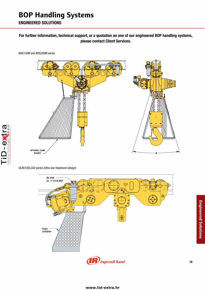
BHS150M and BHS200M series
BOP.Handling.SystemsENGINEERED SOLUTIONS
Air inlet2x 1"1/4 ID BSP
Chaincontainer
EngineeredSolutions
For further information, technical support, or a quotation on one of our engineered BOP handling systems, please contact Client Services.
ULBS100LCA4 series (Ultra‑low headroom design)
www.tid-extra.hr

© 2006 Ingersoll-Rand Company Limited Form No. MHD55148/031006/Printed in U.S.A./1500
Call 1-800-IR HOIST (474-6478) for the distributor nearest you.
Visit our web site at: www.WinchandHoistSolutions.com
Office and distributors in principal cities throughout the world. Contact the nearest Ingersoll Rand office for the name and address of the distributor in your country or write to: Ingersoll Rand, 2724 6th Avenue South, Seattle, WA 98134-0046 USA.
WARNING:This equipment is not designed for transporting people or lifting loads over people. It is the user’s responsibility to determine the suitability of this product for any particular use and to check compliance with applicable regulations. Before installation, see maintenance and operations manual for additional warnings and precautions.
United States Offices
For Order Entry and Order Status:Ingersoll Rand Distribution Center510 Hester Drive, P.O. Box 618, White House, TN 37188Phone: (866) IR4-TOOL Fax: (615) 285-0802 (866) 474-2665
For Technical Support:Client Services2724 Sixth Avenue South, Seattle, WA 98134Phone: (206) 624-0466 Fax: (206) 624-6265Toll free: (866) 273-3278 E-mail: [email protected]
CanadaNational Sales OfficeToronto, Ontario51 Worcester Road, Rexdale, Ontario M9W 4K2Phone: (877) 924-7435 Fax: (416) 213-4510Order Desk: (877) 924-7435 Fax: (416) 213-4506
MexicoIngersoll Rand S.A. de C.V.Boulevard Centro Industrial No.11Industrial Puente de Vigas54070 Tlalnepantla, Estado de MéxicoPhone: 52 (55) 85 03 66 00 Fax: 52 (55) 55 65 30 72 Ext. 6627 & 6628E-mail: mexicot&[email protected]
International
BrazilAlameda Caiapós 311Tamboré - Barueri - São Paulo - Brazil 06460-110Phone: 55-11-2109 . 8950 Fax: 55-11-2109 . 8998
Europe, Middle East and AfricaIngersoll Rand Material Handling – Douai Operations529, avenue Roger Salengro, 59450 SIN LE NOBLE, FrancePhone: (33) 3-27-93-08-08 Fax: (33) 3-27-93-08-19E-mail: [email protected]
Ingersoll Rand SEA Pte. Ltd.42 Benoi Road, Jurong 629903, SingaporePhone: 65-6861-1555 Fax: 65-6862-1373
China Ingersoll Rand Co.7F, Xuhui Yuan Building1089 Zhong Shan Nan 2 Road, Shanghai 200030, ChinaPhone: 86-21-5452 9898 Fax: 86-21-54101110
Ingersoll Rand IndiaIngersoll Rand Wadco Tools Ltd.19, Chetak Apartments, Sheth Motisha Lane (Love Lane)Mazagon, Mumbai 40010 IndiaPhone: 91-120-48955116 (-126) Fax: 91-120-4895127
ContactInformationWORLDWIDE LOCATIONS
www.tid-extra.hr