Embed Size (px)
Citation preview
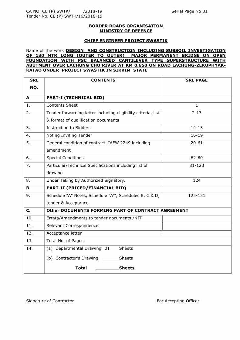
CA NO. CE (P) SWTK/ /2018-19 Serial Page No 01
Tender No. CE (P) SWTK/16/2018-19
BORDER ROADS ORGANISATION
MINISTRY OF DEFENCE
CHIEF ENGINEER PROJECT SWASTIK
Name of the work DESIGN AND CONSTRUCTION INCLUDING SUBSOIL INVESTIGATION
OF 130 MTR LONG (OUTER TO OUTER) MAJOR PERMANENT BRIDGE ON OPEN
FOUNDATION WITH PSC BALANCED CANTILEVER TYPE SUPERSTRUCTURE WITH
ABUTMENT OVER LACHUNG CHU RIVER AT KM 0.650 ON ROAD LACHUNG-ZEKUPHYAK-
KATAO UNDER PROJECT SWASTIK IN SIKKIM STATE
SRL
NO.
CONTENTS SRL PAGE
A PART-I (TECHNICAL BID)
1. Contents Sheet 1
2. Tender forwarding letter including eligibility criteria, list
& format of qualification documents
2-13
3. Instruction to Bidders 14-15
4. Noting Inviting Tender 16-19
5. General condition of contract IAFW 2249 including
amendment
20-61
6. Special Conditions 62-80
7. Particular/Technical Specifications including list of
drawing
81-123
8. Under Taking by Authorized Signatory. 124
B. PART-II (PRICED/FINANCIAL BID)
9. Schedule “A” Notes, Schedule “A‟”, Schedules B, C & D,
tender & Acceptance
125-131
C. Other DOCUMENTS FORMING PART OF CONTRACT AGREEMENT
10. Errata/Amendments to tender documents /NIT
11. Relevant Correspondence
12. Acceptance letter :
13. Total No. of Pages
14. (a) Departmental Drawing 01 Sheets
(b) Contractor‟s Drawing Sheets
Total Sheets
Signature of Contractor For Accepting Officer
CA NO. CE (P) SWTK/ /2018-19 Serial Page No 02
Tender No. CE (P) SWTK/16/2018-19
Registered/AD
FAX- 03592-259210 Headquarters
Tele No. 03592-259208 Chief Engineer
Email:bro-swtk@nic. in Project Swastik
http://www.bro.gov.in PIN-931717
C/O 99 APO
80432/ /E8 09 Jun 2018
M/s…………………………………..
……………………………………….
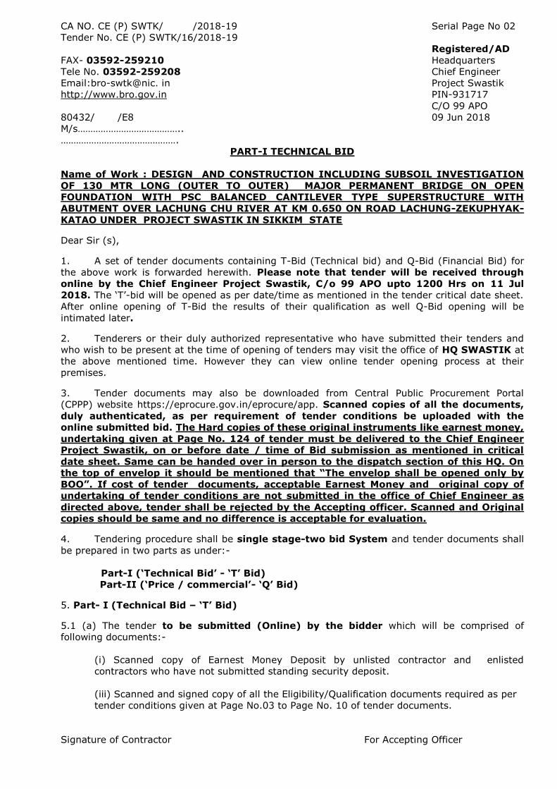
PART-I TECHNICAL BID
Name of Work : DESIGN AND CONSTRUCTION INCLUDING SUBSOIL INVESTIGATION
OF 130 MTR LONG (OUTER TO OUTER) MAJOR PERMANENT BRIDGE ON OPEN
FOUNDATION WITH PSC BALANCED CANTILEVER TYPE SUPERSTRUCTURE WITH
ABUTMENT OVER LACHUNG CHU RIVER AT KM 0.650 ON ROAD LACHUNG-ZEKUPHYAK-
KATAO UNDER PROJECT SWASTIK IN SIKKIM STATE
Dear Sir (s),
1. A set of tender documents containing T-Bid (Technical bid) and Q-Bid (Financial Bid) for
the above work is forwarded herewith. Please note that tender will be received through
online by the Chief Engineer Project Swastik, C/o 99 APO upto 1200 Hrs on 11 Jul
2018. The „T‟-bid will be opened as per date/time as mentioned in the tender critical date sheet.
After online opening of T-Bid the results of their qualification as well Q-Bid opening will be
intimated later.
2. Tenderers or their duly authorized representative who have submitted their tenders and
who wish to be present at the time of opening of tenders may visit the office of HQ SWASTIK at
the above mentioned time. However they can view online tender opening process at their
premises.
3. Tender documents may also be downloaded from Central Public Procurement Portal
(CPPP) website https://eprocure.gov.in/eprocure/app. Scanned copies of all the documents,
duly authenticated, as per requirement of tender conditions be uploaded with the
online submitted bid. The Hard copies of these original instruments like earnest money,
undertaking given at Page No. 124 of tender must be delivered to the Chief Engineer
Project Swastik, on or before date / time of Bid submission as mentioned in critical
date sheet. Same can be handed over in person to the dispatch section of this HQ. On
the top of envelop it should be mentioned that “The envelop shall be opened only by
BOO”. If cost of tender documents, acceptable Earnest Money and original copy of
undertaking of tender conditions are not submitted in the office of Chief Engineer as
directed above, tender shall be rejected by the Accepting officer. Scanned and Original
copies should be same and no difference is acceptable for evaluation.
4. Tendering procedure shall be single stage-two bid System and tender documents shall
be prepared in two parts as under:-
Part-I („Technical Bid‟ - „T‟ Bid)
Part-II („Price / commercial‟- „Q‟ Bid)
5. Part- I (Technical Bid – „T‟ Bid)
5.1 (a) The tender to be submitted (Online) by the bidder which will be comprised of
following documents:-
(i) Scanned copy of Earnest Money Deposit by unlisted contractor and enlisted
contractors who have not submitted standing security deposit.
(iii) Scanned and signed copy of all the Eligibility/Qualification documents required as per
tender conditions given at Page No.03 to Page No. 10 of tender documents.
Signature of Contractor For Accepting Officer
CA NO. CE (P) SWTK/ /2018-19 Serial Page No 03
Tender No. CE (P) SWTK/16/2018-19
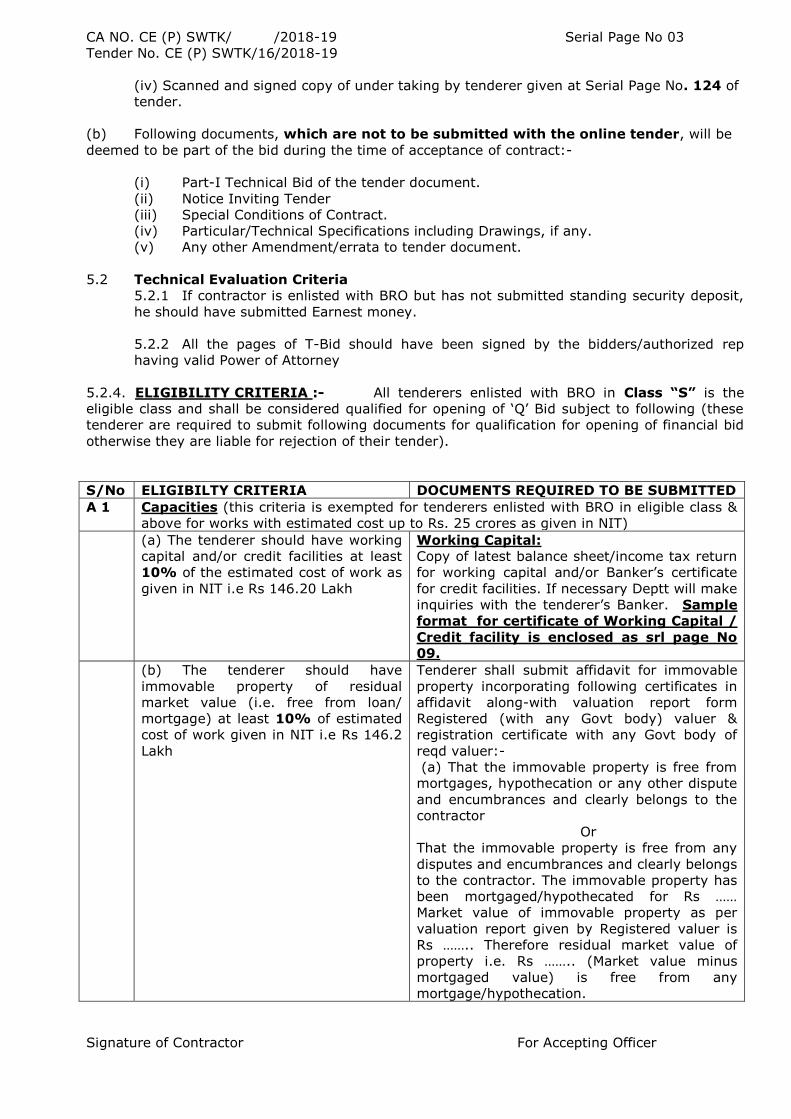
(iv) Scanned and signed copy of under taking by tenderer given at Serial Page No. 124 of
tender.
(b) Following documents, which are not to be submitted with the online tender, will be
deemed to be part of the bid during the time of acceptance of contract:-
(i) Part-I Technical Bid of the tender document.
(ii) Notice Inviting Tender
(iii) Special Conditions of Contract.
(iv) Particular/Technical Specifications including Drawings, if any.
(v) Any other Amendment/errata to tender document.
5.2 Technical Evaluation Criteria
5.2.1 If contractor is enlisted with BRO but has not submitted standing security deposit,
he should have submitted Earnest money.
5.2.2 All the pages of T-Bid should have been signed by the bidders/authorized rep
having valid Power of Attorney
5.2.4. ELIGIBILITY CRITERIA :- All tenderers enlisted with BRO in Class “S” is the
eligible class and shall be considered qualified for opening of „Q‟ Bid subject to following (these
tenderer are required to submit following documents for qualification for opening of financial bid
otherwise they are liable for rejection of their tender).
S/No ELIGIBILTY CRITERIA DOCUMENTS REQUIRED TO BE SUBMITTED
A 1 Capacities (this criteria is exempted for tenderers enlisted with BRO in eligible class &
above for works with estimated cost up to Rs. 25 crores as given in NIT)
(a) The tenderer should have working
capital and/or credit facilities at least
10% of the estimated cost of work as
given in NIT i.e Rs 146.20 Lakh
Working Capital:
Copy of latest balance sheet/income tax return
for working capital and/or Banker‟s certificate
for credit facilities. If necessary Deptt will make
inquiries with the tenderer‟s Banker. Sample
format for certificate of Working Capital /
Credit facility is enclosed as srl page No
09.
(b) The tenderer should have
immovable property of residual
market value (i.e. free from loan/
mortgage) at least 10% of estimated
cost of work given in NIT i.e Rs 146.2
Lakh
Tenderer shall submit affidavit for immovable
property incorporating following certificates in
affidavit along-with valuation report form
Registered (with any Govt body) valuer &
registration certificate with any Govt body of
reqd valuer:-
(a) That the immovable property is free from
mortgages, hypothecation or any other dispute
and encumbrances and clearly belongs to the
contractor
Or
That the immovable property is free from any
disputes and encumbrances and clearly belongs
to the contractor. The immovable property has
been mortgaged/hypothecated for Rs ……
Market value of immovable property as per
valuation report given by Registered valuer is
Rs …….. Therefore residual market value of
property i.e. Rs …….. (Market value minus
mortgaged value) is free from any
mortgage/hypothecation.
Signature of Contractor For Accepting Officer
CA NO. CE (P) SWTK/ /2018-19 Serial Page No 04
Tender No. CE (P) SWTK/16/2018-19
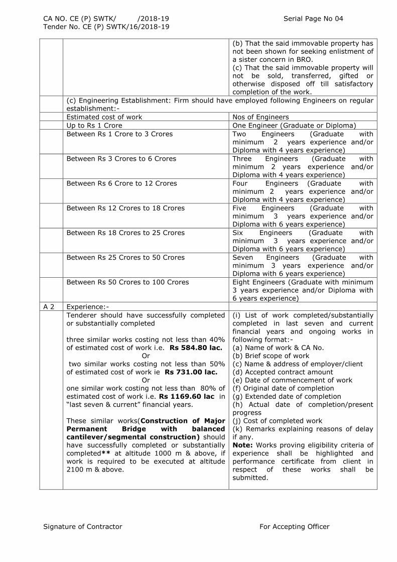
(b) That the said immovable property has
not been shown for seeking enlistment of
a sister concern in BRO.
(c) That the said immovable property will
not be sold, transferred, gifted or
otherwise disposed off till satisfactory
completion of the work.
(c) Engineering Establishment: Firm should have employed following Engineers on regular
establishment:-
Estimated cost of work Nos of Engineers
Up to Rs 1 Crore One Engineer (Graduate or Diploma)
Between Rs 1 Crore to 3 Crores Two Engineers (Graduate with
minimum 2 years experience and/or
Diploma with 4 years experience)
Between Rs 3 Crores to 6 Crores Three Engineers (Graduate with
minimum 2 years experience and/or
Diploma with 4 years experience)
Between Rs 6 Crore to 12 Crores Four Engineers (Graduate with
minimum 2 years experience and/or
Diploma with 4 years experience)
Between Rs 12 Crores to 18 Crores Five Engineers (Graduate with
minimum 3 years experience and/or
Diploma with 6 years experience)
Between Rs 18 Crores to 25 Crores Six Engineers (Graduate with
minimum 3 years experience and/or
Diploma with 6 years experience)
Between Rs 25 Crores to 50 Crores Seven Engineers (Graduate with
minimum 3 years experience and/or
Diploma with 6 years experience)
Between Rs 50 Crores to 100 Crores Eight Engineers (Graduate with minimum
3 years experience and/or Diploma with
6 years experience)
A 2 Experience:-
Tenderer should have successfully completed
or substantially completed
three similar works costing not less than 40%
of estimated cost of work i.e. Rs 584.80 lac.
Or
two similar works costing not less than 50%
of estimated cost of work ie Rs 731.00 lac.
Or
one similar work costing not less than 80% of
estimated cost of work i.e. Rs 1169.60 lac in
“last seven & current” financial years.
These similar works(Construction of Major
Permanent Bridge with balanced
cantilever/segmental construction) should
have successfully completed or substantially
completed** at altitude 1000 m & above, if
work is required to be executed at altitude
2100 m & above.
(i) List of work completed/substantially
completed in last seven and current
financial years and ongoing works in
following format:-
(a) Name of work & CA No.
(b) Brief scope of work
(c) Name & address of employer/client
(d) Accepted contract amount
(e) Date of commencement of work
(f) Original date of completion
(g) Extended date of completion
(h) Actual date of completion/present
progress
(j) Cost of completed work
(k) Remarks explaining reasons of delay
if any.
Note: Works proving eligibility criteria of
experience shall be highlighted and
performance certificate from client in
respect of these works shall be
submitted.
Signature of Contractor For Accepting Officer
CA NO. CE (P) SWTK/ /2018-19 Serial Page No 05
Tender No. CE (P) SWTK/16/2018-19
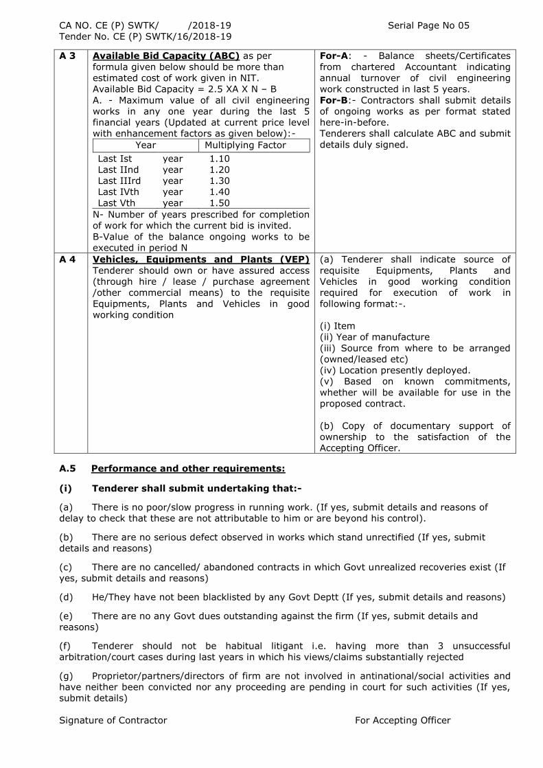
A 3 Available Bid Capacity (ABC) as per
formula given below should be more than
estimated cost of work given in NIT.
Available Bid Capacity = 2.5 XA X N – B
A. - Maximum value of all civil engineering
works in any one year during the last 5
financial years (Updated at current price level
with enhancement factors as given below):-
Year Multiplying Factor
Last Ist year 1.10
Last IInd year 1.20
Last IIIrd year 1.30
Last IVth year 1.40
Last Vth year 1.50
N- Number of years prescribed for completion
of work for which the current bid is invited.
B-Value of the balance ongoing works to be
executed in period N
For-A: - Balance sheets/Certificates
from chartered Accountant indicating
annual turnover of civil engineering
work constructed in last 5 years.
For-B:- Contractors shall submit details
of ongoing works as per format stated
here-in-before.
Tenderers shall calculate ABC and submit
details duly signed.
A 4 Vehicles, Equipments and Plants (VEP)
Tenderer should own or have assured access
(through hire / lease / purchase agreement
/other commercial means) to the requisite
Equipments, Plants and Vehicles in good
working condition
(a) Tenderer shall indicate source of
requisite Equipments, Plants and
Vehicles in good working condition
required for execution of work in
following format:-.
(i) Item
(ii) Year of manufacture
(iii) Source from where to be arranged
(owned/leased etc)
(iv) Location presently deployed.
(v) Based on known commitments,
whether will be available for use in the
proposed contract.
(b) Copy of documentary support of
ownership to the satisfaction of the
Accepting Officer.
A.5 Performance and other requirements:
(i) Tenderer shall submit undertaking that:-
(a) There is no poor/slow progress in running work. (If yes, submit details and reasons of
delay to check that these are not attributable to him or are beyond his control).
(b) There are no serious defect observed in works which stand unrectified (If yes, submit
details and reasons)
(c) There are no cancelled/ abandoned contracts in which Govt unrealized recoveries exist (If
yes, submit details and reasons)
(d) He/They have not been blacklisted by any Govt Deptt (If yes, submit details and reasons)
(e) There are no any Govt dues outstanding against the firm (If yes, submit details and
reasons)
(f) Tenderer should not be habitual litigant i.e. having more than 3 unsuccessful
arbitration/court cases during last years in which his views/claims substantially rejected
(g) Proprietor/partners/directors of firm are not involved in antinational/social activities and
have neither been convicted nor any proceeding are pending in court for such activities (If yes,
submit details)
Signature of Contractor For Accepting Officer
CA NO. CE (P) SWTK/ /2018-19 Serial Page No 06
Tender No. CE (P) SWTK/16/2018-19
(ii) Tenderer shall submit information of all arbitration/court cases decided during
last five & current financial years and also presently in progress as per following
format:-
(a) Name and address of employer
(b) Cause of dispute
(c) Amounts involved
(d) Brief of court judgment/ arbitration award (if published) otherwise present
progress
(iii) Tenderer shall submit the following as other documents :-
(a) Constitution of firm along with copy of partnership deed (in case of partnership firms) and
memorandum of articles and association (in case of limited companies )
(b) Copies of passport of proprietor /partners/directors (if available). If not submitted and
Accepting officer has doubt in character and antecedents of proprietor/partners/directors he may
get these verified from police authorities.
(c) Copies of PAN card of proprietor/partners/directors.
(d) Three copies of such drawings and detailed specifications as would give a clear
idea of the structure proposed by you.
(e) Certificate for ground site inspection: Bidder should certify that he has inspected the
work site and considered all the factors such as weather conditions, temperature variations,
rainfall / snowfall and limited working season while bidding for the tender.
Notes for 5.2.4 above : -
(i) * Eligible class shall be Class E for works with estimated cost up to Rs 0.25 crore (as per NIT),
Class D for works with estimated cost between Rs 0.25 crore to Rs 0.50 crore (as per NIT), Class
C for works with estimated cost between Rs 0.50 crore to Rs 1.00 crore (as per NIT), Class B for
works with estimated cost between Rs 1.00 crore to Rs 3.00 crore (as per NIT), Class A for works
with estimated cost between Rs 3.00 crore to Rs 7.50 crore (as per NIT), Class S for works with
estimated cost between Rs 7.50 crore to Rs 15.00 crore (as per NIT), Class SS for works with
estimated cost between Rs 15.00 crore and above (as per NIT),
(ii) The work may have been executed by the tenderer as prime contractor or as a member of
joint venture or sub contractor. In case project has been executed by a joint venture, weightage
towards experience of the project would be given to each member in proportion to their
participation in the joint venture.
(iii) Substantially completed works means those works which are 90% completed on the date
of submission (i.e. gross value of work done up to the last date of submission is 90% or more of
the original contract price) and continuing satisfactorily.
(iv) Completion cost of works shall be brought to common base date of receipt of tender as
per following formula:-
Completion cost X (1+Period in days from date of completion to date of receipt of tender/365
days ) X 0.10)
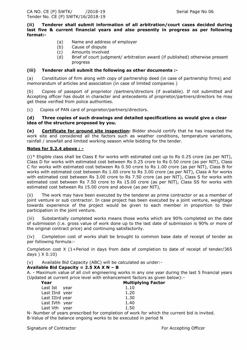
(v) Available Bid Capacity (ABC) will be calculated as under:-
Available Bid Capacity = 2.5 XA X N – B
A. - Maximum value of all civil engineering works in any one year during the last 5 financial years
(Updated at current price level with enhancement factors as given below):-
Year Multiplying Factor
Last Ist year 1.10
Last IInd year 1.20
Last IIIrd year 1.30
Last IVth year 1.40
Last Vth year 1.50
N- Number of years prescribed for completion of work for which the current bid is invited.
B-Value of the balance ongoing works to be executed in period N
Signature of Contractor For Accepting Officer
CA NO. CE (P) SWTK/ /2018-19 Serial Page No 07
Tender No. CE (P) SWTK/16/2018-19
(vii) The tenderers shall indicate actual figures of completion cost of work and value of A
without any enhancement as stated above.
(viii) To determine the altitude of work, average of minimum and maximum altitudes of the
work site shall be considered.
(x) Immovable properties shall be exclusively in the name of contractor/Company and not in
the name of family members/relatives/Others. In case of Limited Companies, these should also
be reflected in Balance Sheet.
(x) Relaxation may be given in any one criteria (except in criteria‟s of Experience and
Performance & other requirements) upto 25% extent i.e. ABC may be permitted up to 75% of
estimated cost of work/VEP may be permitted upto 75% of total Nos of requisite VEP/Working
Capital may be permitted upto 75% of requirement/Immovable property may be permitted up to
75% of requirement/Engineering establishment may be permitted up to 75% of requirement. No
relaxation shall be permitted in criterias of experience and performance & other requirements.
(xi) The tenderer may be afforded an opportunity to clarify or modify his qualification
documents, if necessary, with respect to any rectifiable defects. The tenderer will respond in not
more than 15 days of issue of the clarification letter, failing to which his tender is liable to be
rejected.
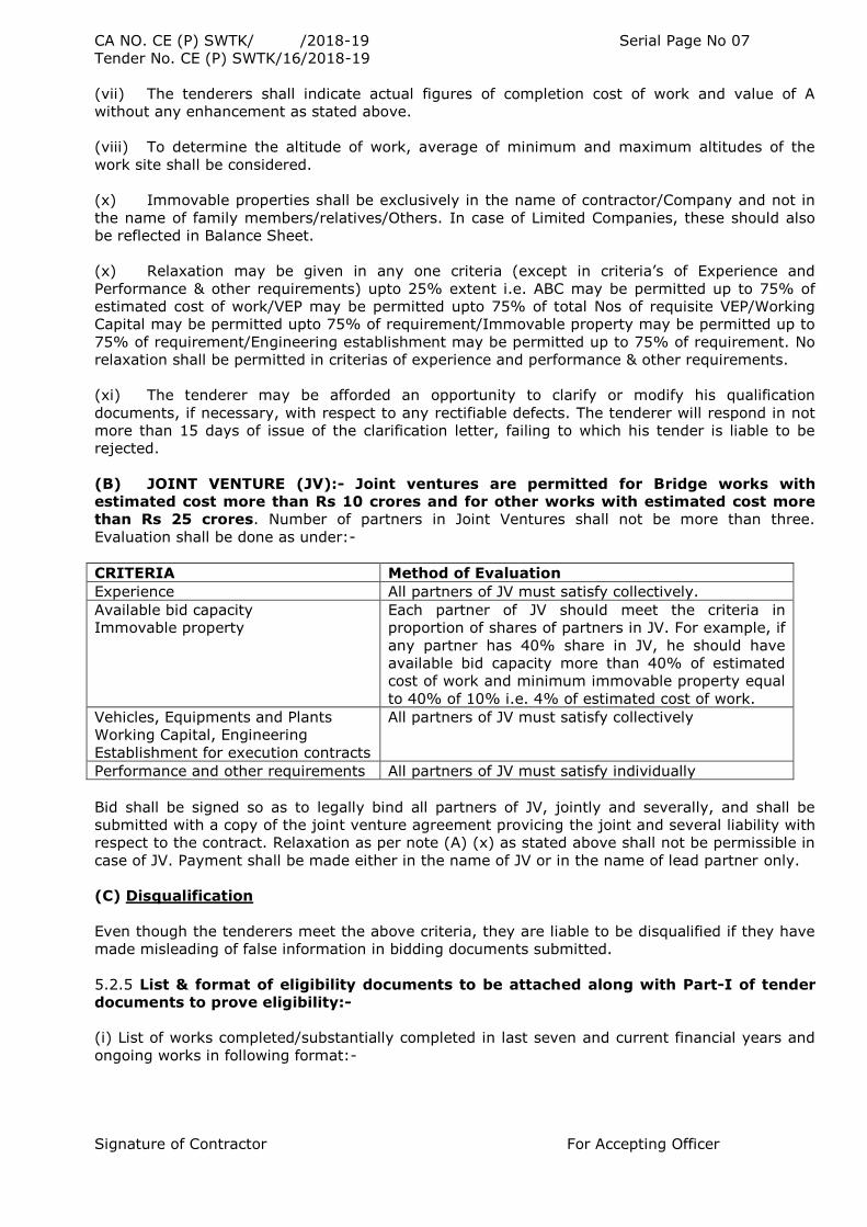
(B) JOINT VENTURE (JV):- Joint ventures are permitted for Bridge works with
estimated cost more than Rs 10 crores and for other works with estimated cost more
than Rs 25 crores. Number of partners in Joint Ventures shall not be more than three.
Evaluation shall be done as under:-
CRITERIA Method of Evaluation
Experience All partners of JV must satisfy collectively.
Available bid capacity
Immovable property
Each partner of JV should meet the criteria in
proportion of shares of partners in JV. For example, if
any partner has 40% share in JV, he should have
available bid capacity more than 40% of estimated
cost of work and minimum immovable property equal
to 40% of 10% i.e. 4% of estimated cost of work.
Vehicles, Equipments and Plants
Working Capital, Engineering
Establishment for execution contracts
All partners of JV must satisfy collectively
Performance and other requirements All partners of JV must satisfy individually
Bid shall be signed so as to legally bind all partners of JV, jointly and severally, and shall be
submitted with a copy of the joint venture agreement provicing the joint and several liability with
respect to the contract. Relaxation as per note (A) (x) as stated above shall not be permissible in
case of JV. Payment shall be made either in the name of JV or in the name of lead partner only.
(C) Disqualification
Even though the tenderers meet the above criteria, they are liable to be disqualified if they have
made misleading of false information in bidding documents submitted.
5.2.5 List & format of eligibility documents to be attached along with Part-I of tender
documents to prove eligibility:-
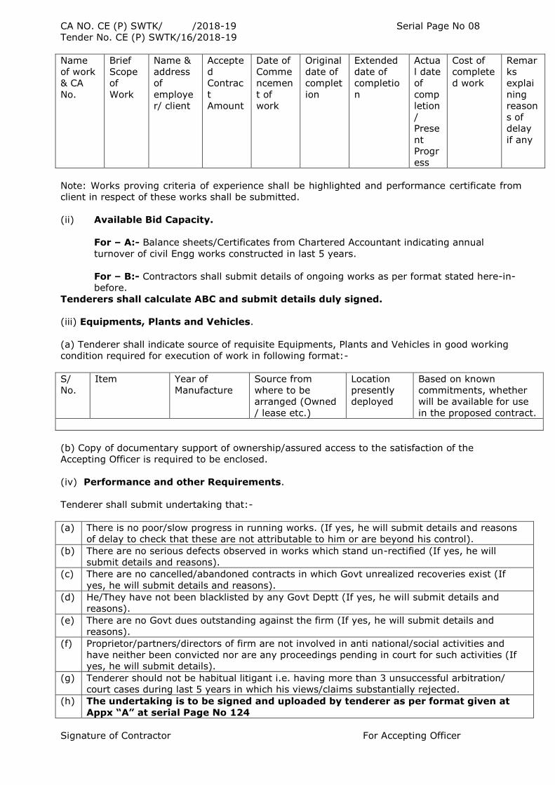
(i) List of works completed/substantially completed in last seven and current financial years and
ongoing works in following format:-
Signature of Contractor For Accepting Officer
CA NO. CE (P) SWTK/ /2018-19 Serial Page No 08
Tender No. CE (P) SWTK/16/2018-19
Name
of work
& CA
No.
Brief
Scope
of
Work
Name &
address
of
employe
r/ client
Accepte
d
Contrac
t
Amount
Date of
Comme
ncemen
t of
work
Original
date of
complet
ion
Extended
date of
completio
n
Actua
l date
of
comp
letion
/
Prese
nt
Progr
ess
Cost of
complete
d work
Remar
ks
explai
ning
reason
s of
delay
if any
Note: Works proving criteria of experience shall be highlighted and performance certificate from
client in respect of these works shall be submitted.
(ii) Available Bid Capacity.
For – A:- Balance sheets/Certificates from Chartered Accountant indicating annual
turnover of civil Engg works constructed in last 5 years.
For – B:- Contractors shall submit details of ongoing works as per format stated here-in-
before.
Tenderers shall calculate ABC and submit details duly signed.
(iii) Equipments, Plants and Vehicles.
(a) Tenderer shall indicate source of requisite Equipments, Plants and Vehicles in good working
condition required for execution of work in following format:-
S/
No.
Item Year of
Manufacture
Source from
where to be
arranged (Owned
/ lease etc.)
Location
presently
deployed
Based on known
commitments, whether
will be available for use
in the proposed contract.
(b) Copy of documentary support of ownership/assured access to the satisfaction of the
Accepting Officer is required to be enclosed.
(iv) Performance and other Requirements.
Tenderer shall submit undertaking that:-
(a) There is no poor/slow progress in running works. (If yes, he will submit details and reasons
of delay to check that these are not attributable to him or are beyond his control).
(b) There are no serious defects observed in works which stand un-rectified (If yes, he will
submit details and reasons).
(c) There are no cancelled/abandoned contracts in which Govt unrealized recoveries exist (If
yes, he will submit details and reasons).
(d) He/They have not been blacklisted by any Govt Deptt (If yes, he will submit details and
reasons).
(e) There are no Govt dues outstanding against the firm (If yes, he will submit details and
reasons).
(f) Proprietor/partners/directors of firm are not involved in anti national/social activities and
have neither been convicted nor are any proceedings pending in court for such activities (If
yes, he will submit details).
(g) Tenderer should not be habitual litigant i.e. having more than 3 unsuccessful arbitration/
court cases during last 5 years in which his views/claims substantially rejected.
(h) The undertaking is to be signed and uploaded by tenderer as per format given at
Appx “A” at serial Page No 124
Signature of Contractor For Accepting Officer
CA NO. CE (P) SWTK/ /2018-19 Serial Page No 09
Tender No. CE (P) SWTK/16/2018-19
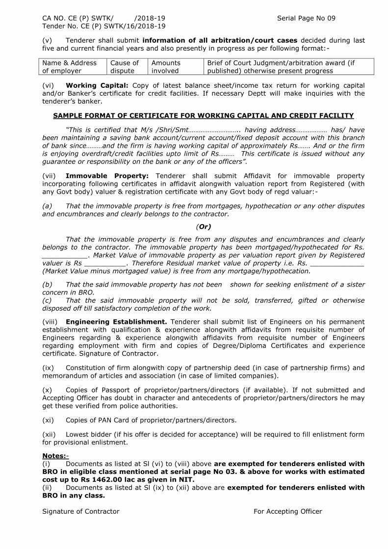
(v) Tenderer shall submit information of all arbitration/court cases decided during last
five and current financial years and also presently in progress as per following format:-
Name & Address
of employer
Cause of
dispute
Amounts
involved
Brief of Court Judgment/arbitration award (if
published) otherwise present progress
(vi) Working Capital: Copy of latest balance sheet/income tax return for working capital
and/or Banker‟s certificate for credit facilities. If necessary Deptt will make inquiries with the
tenderer‟s banker.
SAMPLE FORMAT OF CERTIFICATE FOR WORKING CAPITAL AND CREDIT FACILITY
“This is certified that M/s /Shri/Smt……………………….. having address……………… has/ have
been maintaining a saving bank account/current account/fixed deposit account with this branch
of bank since………and the firm is having working capital of approximately Rs……. And or the firm
is enjoying overdraft/credit facilities upto limit of Rs……… This certificate is issued without any
guarantee or responsibility on the bank or any of the officers”.
(vii) Immovable Property: Tenderer shall submit Affidavit for immovable property
incorporating following certificates in affidavit alongwith valuation report from Registered (with
any Govt body) valuer & registration certificate with any Govt body of regd valuar:-
(a) That the immovable property is free from mortgages, hypothecation or any other disputes
and encumbrances and clearly belongs to the contractor.
(Or)
That the immovable property is free from any disputes and encumbrances and clearly
belongs to the contractor. The immovable property has been mortgaged/hypothecated for Rs.
___________. Market Value of immovable property as per valuation report given by Registered
valuer is Rs __________. Therefore Residual market value of property i.e. Rs. _____________
(Market Value minus mortgaged value) is free from any mortgage/hypothecation. (b) That the said immovable property has not been shown for seeking enlistment of a sister
concern in BRO.
(c) That the said immovable property will not be sold, transferred, gifted or otherwise
disposed off till satisfactory completion of the work.
(viii) Engineering Establishment. Tenderer shall submit list of Engineers on his permanent
establishment with qualification & experience alongwith affidavits from requisite number of
Engineers regarding & experience alongwith affidavits from requisite number of Engineers
regarding employment with firm and copies of Degree/Diploma Certificates and experience
certificate. Signature of Contractor. (ix) Constitution of firm alongwith copy of partnership deed (in case of partnership firms) and
memorandum of articles and association (in case of limited companies).
(x) Copies of Passport of proprietor/partners/directors (if available). If not submitted and
Accepting Officer has doubt in character and antecedents of proprietor/partners/directors he may
get these verified from police authorities.
(xi) Copies of PAN Card of proprietor/partners/directors.
(xii) Lowest bidder (if his offer is decided for acceptance) will be required to fill enlistment form
for provisional enlistment.
Notes:-
(i) Documents as listed at Sl (vi) to (viii) above are exempted for tenderers enlisted with
BRO in eligible class mentioned at serial page No 03. & above for works with estimated
cost up to Rs 1462.00 lac as given in NIT.
(ii) Documents as listed at Sl (ix) to (xii) above are exempted for tenderers enlisted with
BRO in any class.
Signature of Contractor For Accepting Officer
CA NO. CE (P) SWTK/ /2018-19 Serial Page No 10
Tender No. CE (P) SWTK/16/2018-19
(iii) Affidavits shall be submitted on Non-Judicial stamp papers of appropriate values duly
attested by the Magistrate/Notary Public.
(iv) Photocopies of documents shall be attested by Gazetted officer/Public notary and also self
attested.
5.3 The bidder should meet all the technical evaluation criteria indicated in the bid
documents in order that the bid is considered to be technically responsive and the
bidder qualifying to have its Financial Bid opened.
6. Part-II („Financial Bid‟- „Q‟ Bid)
6.1 (a) The rates to be quoted online by the bidder in the BOQ (Schedule „A‟).
(b) The Part-II Financial Bid shall comprise of the following which is required to be signed
by the bidder during time of acceptance of contract:-
(i) BOQ (Schedule „A‟) Notes
(ii) BOQ (Schedule „A‟)
(iii) Schedule „B, C & D.
(iv) Tender page
6.2 Q-bid evaluation Commercial bids will be reviewed to ensure that the figures indicated
therein are consistent with the details of the corresponding technical bids.- Arithmetical
corrections shall be made as per General Condition of Contracts 6 (A)(A) of IAFW -2249.
Commercial Bids of „Technically Responsive‟ Bidders shall be evaluated on the following:-
(i) Commercial Bids shall only be furnished in Schedule „A‟ forming part of
the Tender documents.
(ii) All payment Terms as forming part of Clause of General Condition of Contract have
been accepted.
(iii) Completion Period as indicated in Tender Document have been accepted.
(iv) All General Conditions of Contract have been accepted.
(v) All Special Conditions of Contract have been accepted.
6.2 Determination of L1 : L1 shall be arrived at by taking into account the rates quoted in
Sch ‟A‟ which shall be inclusive of all taxes and duties leviable.
6.3 Conditional bids‟ shall be treated as being „Non Responsive‟– NO „Conditional‟
bids shall be accepted.
6.4 Negotiations, if any, shall be carried out ONLY with the Lowest evaluated responsive bidder in
accordance with CVC guidelines on the subject. 7. Bids shall be submitted online only at CPPP website:
https://eprocure.gov.in/eprocure/app. Manual bids shall not be accepted. Tenderer are
advised to follow the instructions provided in the „Instructions to the Tenderer for the e-
submission of the bids online through the Central Public Procurement Portal for e
Procurement at https://eprocure.gov.in/eprocure/app.
8. Tender shall be opened as per date/time as mentioned in the tender critical date sheet
indicated in Para I herein before in the presence of tenderers or their authorized representative
whoever wish to be present. Part-I (Technical bid) only shall be opened first on date mentioned
in the critical date sheet. Part-II (Financial Bid) shall not be opened. Part I (Technical bid) will be
opened and evaluated as per BRO technical evaluation criteria given in the tender documents.
Qualified tenderer will accordingly be informed along with date & time of opening of their
Financial Bid (however date of opening of Financial bid shall not be earlier than 7 days from date
of opening of Part-I) Technical bid. Unqualified tenderer will also be informed through e-mail.
Part-II (Financial bid) shall be opened on the appointed date/time in the presence of such
tenderer who choose to be present and the amounts quoted by the tenderers shall be read out by
the opening officer(s) to the tenderers. However they can view online tender opening process at
their premises.
Signature of Contractor For Accepting Officer
CA NO. CE (P) SWTK/ /2018-19 Serial Page No 11
Tender No. CE (P) SWTK/16/2018-19
9. The Chief Engineer Project Swastik will be Accepting Officer here-in-after referred to
as such for the purpose of this contract.
10. Tenderers are requested to quote the rates in figures only in the provided column in
BOQ (schedule A) given in Excel sheet.
11. If tenderers desire that any condition or stipulation given in the tender documents is to be
modified or deleted, they may submit their comments/suggestions before last working date of
clarification as shown in critical date details in subject tender ID for consideration by the Deptt
for issue of corrigendum/amendments to tender documents. If deptt considers comments/
suggestions suitable, corrigendum/amendments to tender documents shall be issued and also
uploaded on BRO/CPPP websites. If deptt does not consider comments/suggestion suitable,
corrigendum/amendments to tender documents shall not be issued/uploaded on BRO/CPPP
websites and tenderers shall quote strictly complying with the various provisions given in the
tender documents. Any tender who stipulates any alterations to any of the
conditions/provisions laid down in tender documents (including
corrigendum/amendments) or which proposes any other conditions of any description
whatsoever is liable to be rejected.
12. The tenderers are advised to visit the work site to acquaint themselves of working and site
conditions, before submitting their tender. The submission of tender by a person implies that he
has read this tender forwarding letter, the conditions of contract and has made himself aware of
the scope and specifications of the work to be done and of the conditions and other factors, site
conditions, taxes and levies prevailing etc which may affect the quotation and execution of the
work.
13. Tenderer must be very careful to deliver a bonafide tender; failing which the tenders are
liable to be rejected. Tenderers are, therefore, advised to ensure that their tender must satisfy
each and every conditions laid down in tender documents.
14. Tenderers must ensure that their tender is unambiguous and is completed in all respects.
Their particular attention is drawn to the following requirements, which must be complied with:-
(a) If a tender is submitted on behalf of a firm, it may be signed either by all partners or a
person holding a valid power of attorney from all the partners constituting the firm. The
person signing the tender on behalf of another or on behalf of a firm shall attach (Scanned
Copy) with tender a proper power of attorney duly executed in his favour by such other
person or by all the partners stating specifically that he has authority to bind such other
person(s) or the firm as the case may be in all matters pertaining to the contract including
the arbitration clause. The power of attorney shall be executed as indicated below:-
(i) In case of proprietorship concern if tender is signed by other than proprietor,
person signing tender documents should hold power of attorney from proprietor.
(ii) In case of partnership concern, power of attorney shall be executed by all
partners.
(iii) In case of company, power of attorney shall be executed in accordance with
the constitution of company.
(b) The under taking is to be signed and attached by tenderer as per format given at
Appendix „A‟ at serial Page No.124.
15. Tenderer who has participated in this the tender action shall not temper/modify the tender
form in any manner. In case if the same is found to be tempered /modified in any manner,
tender will be completely rejected and tenderer is liable to be banned from doing business with
BRO.
16. Your attention is drawn to the Indian Official Secret Act-1923 (XIX of 1923) as amended
up to date particularly section 5 thereof.
Signature of Contractor For Accepting Officer
CA NO. CE (P) SWTK/ /2018-19 Serial Page No 12
Tender No. CE (P) SWTK/16/2018-19
17. Earnest Money:-
(a) Earnest money is not required to be attached with tender by the enlisted contractor
with BRO (term “enlisted contractor” used in tender documents means “enlisted contractor
with BRO”) who have submitted standing security but same is required enlisted contractor
with BRO, who have not submitted standing security deposit.
(b) Enlisted contractors with BRO, who have not submitted standing security deposit will
submit the tender accompanied with Earnest Money amounting to Rs 10,56,000/-
(Rupees Ten lac Fifty Six thousand only) in the shape of call Receipt/Term Deposit
Receipt/Special Term Deposit Receipt in favour of Chief Engineer Project Swastik, C/O
99 APO by nationalized/scheduled Bank. Tender not accompanied with earnest
money will not be considered for acceptance. The amount of this receipt should be
basic amount and not their maturity value. Any deposit lying with the department in any
form against any other tender and/or contract shall not be considered for adjustment as
the earnest money against the tender. Any tender not accompanied with the earnest
money in the form as indicated here-in-before or accompanied with any
letter/communication containing any request for adjustment of any other deposit as
earnest money shall be treated as non bonafied tender.
(c) Earnest money shall be returned to unsuccessful bidder (other than L-1) after opening
of Financial Bids and to successful (L-1) bidder after receipt of security deposit.
18. Security Deposit:-
(a) In case of a enlisted contractor, who has submitted the Standing Security Deposit,
but the tendered cost of the work exceeds the upper tendering limit of the contractor and
the Accepting Officer decides to accept this tender, the contractor has to lodge additional
Security Deposit (difference of security deposit of work and standing security deposit)as
notified by the Accepting Officer in the prescribed form within 30 days of the receipt by
him of notification of acceptance of the tender, failing which this sum shall be recovered
from the first RAR payment, and if the date of first RAR is prior to the period mentioned
above, the same shall be recovered from such payments.
(b) In case of unenlisted contractor/enlisted contractor who has not deposited the
standing security deposit, and the Accepting Officer decides to accept his tender, then
contractor has to lodge security deposit as notified by the Accepting Officer in the
prescribed form within 30 days of the receipt by him of notification of acceptance of the
tender, failing which this sum shall be recovered from the first RAR payment, and if the
date of first RAR is prior to the period mentioned above, the same shall be recovered from
such payment. The Security Deposit amount will be communicated as per departmental
norms but in no case the same shall be more than Rs 18,75,000.00 (Rupees Eighteen
Lakhs Seventy five Thousand Only). Departmental norms of security deposit may be
seen in any office of BRO.
(c) The security deposit amount for this work shall be 25 % more than the amount of
earnest money deposit calculated as per scale laid down based on the contract amount
The amount of security deposit shall, however, not exceed Rs 11,25,000/-. The security
deposit is required to be lodged in the prescribed form on receipt in writing from Accepting
Officer.
(d) The contractor may at his discretion furnish in lieu of Additional Security Deposit or
Security Deposit, a Bank Guarantee Bond executed by the State Bank of India and
other nationalized banks ; Guarantee Bonds by a scheduled bank and counter
signed by the State Bank of India or recommended by the Reserve Bank of India
for acceptance. The form of Bank Guarantee Bond may be seen in any office of BRO.
19. The Accepting Officer reserves the right to accept a tender submitted by a Public
Undertaking, giving a purchase preference over other tender(s) as are admissible under the
Government Policy. No claim for any compensation or otherwise shall be admissible to such
tenders whose tenders may be rejected on account of the said policy.
Signature of Contractor For Accepting Officer
CA NO. CE (P) SWTK/ /2018-19 Serial Page No 13
Tender No. CE (P) SWTK/16/2018-19
20. The tender shall remain open for acceptance for a period of 120 days from the date of
opening of Price- Bid of the tender (excluding the date of opening).
21. On acceptance of tender, the name of authorized representative (s) of the contractors
who would be responsible for taking instructions from Engineer-in-Charge or its authorized
representative shall be intimated by the contractor within 7 days of issue of Acceptance letter.
22. Revision/Modification of quoted Price:-
(a) The tenderer shall quote his rates in figures only in the provided column in schedule A
given in Excel sheet only. In case the tenderer has to revise/ modify the rates quoted in the
shedule‟A‟ before tender submission end date as mentioned in critical date sheet, resubmission
bid shall be allowed.
(b) In case the tenderer has to revise /modify /withdraw his quoted rates / offer after it is
submitted, he may do so on his own online before the latest date & time fixed for submission of
tenders. Any revision/ modification in offer / withdrawal of offer in the form of an open letter
shall not be taken into account, while considering in his originally offers.
(c) The tenderer shall not be permitted to revise/modify/withdraw unopened Financial Bid
after closure of the time fixed for receipt of tender
23. Revocation of offer:-
In the event of lowest tenderer revokes his offer or revise his rates upward (which will be
treated as revocation of offer), after opening of tenders and before expiry of original validity
period stipulated in tender documents, the earnest money deposited by him shall be forfeited. In
case of BRO enlisted contractors, the amount equal to the earnest money stipulated in the Notice
Tender, shall be notified to the tenderer for depositing the amount through MRO, failing which
the amount shall be recovered from any payment due to such contractor or shall be adjusted
from the Standing Security Deposit. In addition, L-1 tenderer revoking offer and his related firms
shall not be issued the tender in second or subsequent calls of subject work.
Signature of Contractor For Accepting Officer
CA NO. CE (P) SWTK/ /2018-19 Serial Page No 14
Tender No. CE (P) SWTK/16/2018-19
INSTRUCTIONS TO BIDDERS
24. Instructions to the Bidders to submit the bids online through the Central Public
Procurement Portal website for e-Procurement at https://eprocure.gov.in/eprocure/app:-
(a) Possession of valid Digital Signature Certificate (DSC) and enrollment/registration of
the contractors/bidders on the e-procurement/etender portal is a prerequisite for e-
tendering.
(b) Bidder should do the enrollment in the e-Procurement site using the “Click here to
Enroll” option available on the home page. Portal enrollment is generally free of charge.
During enrollment/registration, the bidders should provide the correct/true information
including valid email ID. All the correspondence shall be made directly with the
contractors/bidders through email ID provided.
(c) Bidder need to login to the site through their user ID/ password chosen during
enrollment/ registration.
(d) The Digital Signature Certificate (Class II or Class III Certificates with signing key
usage) issued by SIFY/TCS/nCode/eMudra or any Certifying Authority recognized by CCA
India on eToken/SmartCard, should be registered.
(e) The DSC that is registered only should be used by the bidder and should ensure safety
of the same.
(f) Contractor/Bidder may go through the tenders published on the site and download the
required tender documents/schedules for the tenders he/she is interested.
(g) After downloading / getting the tender documents/schedules, the Bidder should go
through them carefully and then submit the documents as asked, otherwise bid will be
rejected.
(h) If there are any clarifications, this may be obtained online through the tender site, or
through the contact details. Bidder should take into account the corrigendum published
before submitting the bids online.
(j) From my tender folder, he selects the tender to view all the details indicated.
(k) Bidder then log in to the site through the secured login by giving the user ID/
password chosen during enrolment/registration and then by giving the password of the
eToken/SmartCard to access DSC.
(l) Bidder selects the tender which he/she is interested in by using the search option &
then moves it to the „my tenders‟ folder.
(m) It is construed that the bidder has read all the terms and conditions before submitting
their offer. Bidder should go through the tender schedules carefully and upload the
documents as asked; otherwise, the bid will be rejected.
(n) Bidder, in advance, should get ready the bid documents to be submitted as indicated
in the tender documents/schedule and generally, they can be in PDF/xls/rar/zip/dwf
formats. If there is more than one document, they can be clubbed together and can be
provided in the requested format. Each document to be uploaded through online for the
tenders should be less than 2 MB. If any document is more than 2MB, it can be reduced
through zip/rar and the same can be uploaded, if permitted. Bidders Bid documents may
be scanned with 100 dpi with black and white option. However of the file size is less than
1 MB the transaction uploading time will be very fast.
(o) If there are any clarifications, this may be obtained through the site, or during the
pre-bid meeting if any. Bidder should take into account the corrigendum published from
time to time before submitting the online bids.
(p) The Bidders can update well in advance, the documents such as certificates, annual
report details etc., under My Space option and these can be selected as per tender
requirements and then send along with bid documents during bid submission. This will
facilitate the bid submission process faster by reducing upload time of bids.
(q) Bidder should submit the Tender Fee/ EMD as specified in the tender. The original
should be posted/couriered/given in person to the Tender Inviting Authority, at least one
working date prior bid submission due date & time for the tender. Scanned copy of the
instrument should be uploaded as part of the offer.
Signature of Contractor For Accepting Officer
CA NO. CE (P) SWTK/ /2018-19 Serial Page No 15
Tender No. CE (P) SWTK/16/2018-19
(r) While submitting the bids online, the bidder reads the terms & conditions and accepts
the same to proceed further to submit the bid packets.
(s) The bidder has to select the payment option as offline to pay the Tender FEE/ EMD as
applicable and enter details of the instruments.
(t) The details of the DD/any other accepted instrument, physically sent, should tally with
the details available in the scanned copy and the data entered during bid submission time.
Otherwise submitted bid will not be acceptable.
(u) The bidder has to digitally sign and upload the required bid documents one by one as
indicated. Bidders to note that the very act of using DSC for downloading the bids and
uploading their offers shall be deemed to be a confirmation that they have read all
sections and pages of the bid document including General conditions of contract without
any exception and have understood the entire document and are clear about the
requirements of the tender requirements.
(v) The bidder has to upload the relevant files required as indicated in the cover content.
In case of any irrelevant files, the bid will be rejected.
(w) If the Financial Bid format is provided in a spread sheet file like BoQ_xxxx.xls, the
rates offered should be entered in the allotted space only and uploaded after filling the
relevant columns. The Financial Bid/BOQ template must not be modified/replaced by the
bidder; else the bid submitted is liable to be rejected for this tender.
(x) The bidders are requested to submit the bids through online e-tendering system to the
Tender Inviting Authority (TIA) well before the bid submission end date & time (as per
Server System Clock). The TIA will not be held responsible for any sort of delay or the
difficulties faced during the submission of bids online by the bidders at the eleventh hour. (y) After the bid submission (ie after Clicking “Freeze Bid Submission” in the portal), the
acknowledgement number, given by the system should be printed by the bidder and kept
as a record of evidence for online submission of bid for the particular tender and will also
act as an entry pass to participate in the bid opening date.
(z) The time settings fixed in the server side & displayed at the top of the tender site, will
be valid for all actions of requesting, bid submission, bid opening etc., in the e-tender
system. The bidders should follow this time during bid submission.
(aa) All the data being entered by the bidders would be encrypted using PKI encryption
techniques to ensure the secrecy of the data. The data entered will not viewable by
unauthorized persons during bid submission & not be viewable by any one until the time
of bid opening.
(ab) Any bid document that is uploaded to the server is subjected to symmetric encryption
using a system generated symmetric key. Further this key is subjected to asymmetric
encryption using buyers/bid openers public keys. Overall, the uploaded tender documents
become readable only after the tender opening by the authorized bid openers.
(ac) The confidentiality of the bids is maintained since the secured Socket Layer 128 bit
encryption technology is used. Data storage encryption of sensitive fields is done.
(ad) The bidder should logout of the tendering system using the normal logout option
available at the top right hand corner and not by selecting the (X) exit option in the
browser.
(ae) For any queries regarding e-tendering process, the bidders are requested to contact
as provided in the tender document. Parallely for any further queries, the bidders are
asked to contact over phone: 1-800-233-7315 or send a mail over to [email protected].
Signature of Contractor For Accepting Officer
CA NO CE (P) SWTK/ /2018-19 Serial page No. 16
Tender No. CE (P) SWTK/16/2018-19
NOTICE INVITING TENDERS
(NATIONAL COMPETITIVE BIDDING)
BORDER ROADS ORGANISATION
MINISTRY OF DEFENCE
GOVT OF INDIA
CHIEF ENGINEER PROJECT SWASTIK
NIT No. SWTK/NIT- 16 /2018-19
1. Online bids are invited on single stage two bid system for DESIGN AND
CONSTRUCTION INCLUDING SUBSOIL INVESTIGATION OF 130 MTR LONG (OUTER TO
OUTER) MAJOR PERMANENT BRIDGE ON OPEN FOUNDATION WITH PSC BALANCED
CANTILEVER TYPE SUPERSTRUCTURE WITH ABUTMENT OVER LACHUNG CHU RIVER AT
KM 0.650 ON ROAD LACHUNG-ZEKUPHYAK-KATAO UNDER PROJECT SWASTIK IN
SIKKIM STATE
The title of above heading on CPP site https://eprocure.gov.in/eprocure/app is DESIGN AND
CONSTRUCTION INCLUDING SUBSOIL INVESTIGATION OF 130 MTR LONG (OUTER TO
OUTER) MAJOR PERMANENT BRIDGE ON OPEN FOUNDATION WITH PSC BALANCED
CANTILEVER TYPE SUPERSTRUCTURE WITH ABUTMENT OVER LACHUNG CHU RIVER AT
KM 0.650 ON ROAD LACHUNG-ZEKUPHYAK-KATAO UNDER PROJECT SWASTIK IN
SIKKIM STATE
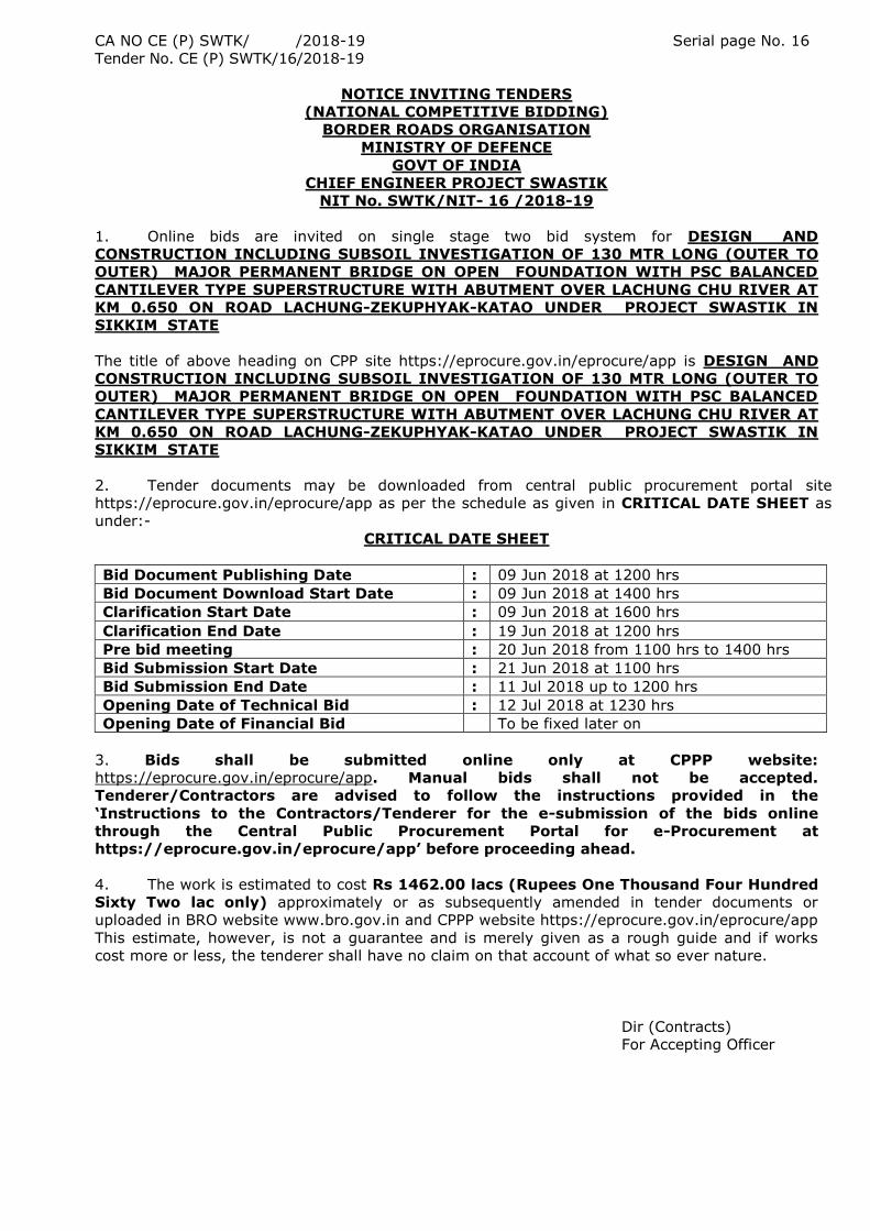
2. Tender documents may be downloaded from central public procurement portal site
https://eprocure.gov.in/eprocure/app as per the schedule as given in CRITICAL DATE SHEET as
under:-
CRITICAL DATE SHEET
Bid Document Publishing Date : 09 Jun 2018 at 1200 hrs
Bid Document Download Start Date : 09 Jun 2018 at 1400 hrs
Clarification Start Date : 09 Jun 2018 at 1600 hrs
Clarification End Date : 19 Jun 2018 at 1200 hrs
Pre bid meeting : 20 Jun 2018 from 1100 hrs to 1400 hrs
Bid Submission Start Date : 21 Jun 2018 at 1100 hrs
Bid Submission End Date : 11 Jul 2018 up to 1200 hrs
Opening Date of Technical Bid : 12 Jul 2018 at 1230 hrs
Opening Date of Financial Bid To be fixed later on
3. Bids shall be submitted online only at CPPP website:
https://eprocure.gov.in/eprocure/app. Manual bids shall not be accepted.
Tenderer/Contractors are advised to follow the instructions provided in the
„Instructions to the Contractors/Tenderer for the e-submission of the bids online
through the Central Public Procurement Portal for e-Procurement at
https://eprocure.gov.in/eprocure/app‟ before proceeding ahead.
4. The work is estimated to cost Rs 1462.00 lacs (Rupees One Thousand Four Hundred
Sixty Two lac only) approximately or as subsequently amended in tender documents or
uploaded in BRO website www.bro.gov.in and CPPP website https://eprocure.gov.in/eprocure/app
This estimate, however, is not a guarantee and is merely given as a rough guide and if works
cost more or less, the tenderer shall have no claim on that account of what so ever nature.
Dir (Contracts)
For Accepting Officer
CA NO CE (P) SWTK/ /2018-19 Serial page No. 17
Tender No. CE (P) SWTK/16/2018-19
(NOTICE OF TENDER (contd…….)
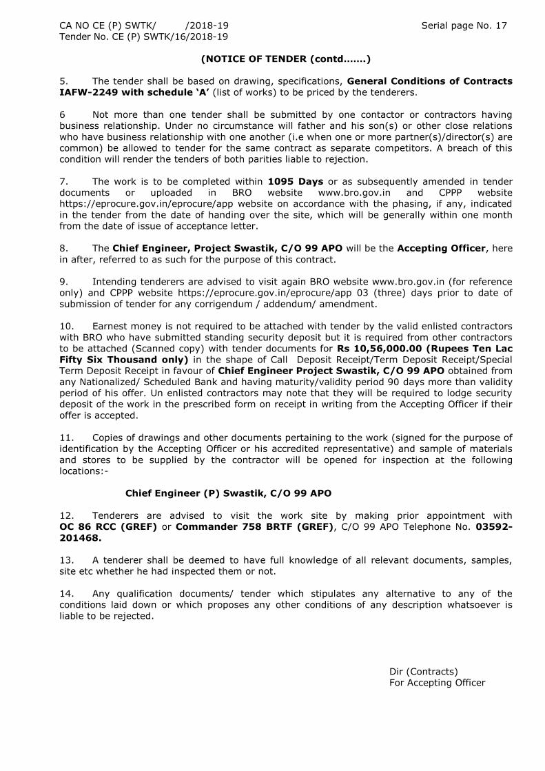
5. The tender shall be based on drawing, specifications, General Conditions of Contracts
IAFW-2249 with schedule „A‟ (list of works) to be priced by the tenderers.
6 Not more than one tender shall be submitted by one contactor or contractors having
business relationship. Under no circumstance will father and his son(s) or other close relations
who have business relationship with one another (i.e when one or more partner(s)/director(s) are
common) be allowed to tender for the same contract as separate competitors. A breach of this
condition will render the tenders of both parities liable to rejection.
7. The work is to be completed within 1095 Days or as subsequently amended in tender
documents or uploaded in BRO website www.bro.gov.in and CPPP website
https://eprocure.gov.in/eprocure/app website on accordance with the phasing, if any, indicated
in the tender from the date of handing over the site, which will be generally within one month
from the date of issue of acceptance letter.
8. The Chief Engineer, Project Swastik, C/O 99 APO will be the Accepting Officer, here
in after, referred to as such for the purpose of this contract.
9. Intending tenderers are advised to visit again BRO website www.bro.gov.in (for reference
only) and CPPP website https://eprocure.gov.in/eprocure/app 03 (three) days prior to date of
submission of tender for any corrigendum / addendum/ amendment.
10. Earnest money is not required to be attached with tender by the valid enlisted contractors
with BRO who have submitted standing security deposit but it is required from other contractors
to be attached (Scanned copy) with tender documents for Rs 10,56,000.00 (Rupees Ten Lac
Fifty Six Thousand only) in the shape of Call Deposit Receipt/Term Deposit Receipt/Special
Term Deposit Receipt in favour of Chief Engineer Project Swastik, C/O 99 APO obtained from
any Nationalized/ Scheduled Bank and having maturity/validity period 90 days more than validity
period of his offer. Un enlisted contractors may note that they will be required to lodge security
deposit of the work in the prescribed form on receipt in writing from the Accepting Officer if their
offer is accepted.
11. Copies of drawings and other documents pertaining to the work (signed for the purpose of
identification by the Accepting Officer or his accredited representative) and sample of materials
and stores to be supplied by the contractor will be opened for inspection at the following
locations:-
Chief Engineer (P) Swastik, C/O 99 APO
12. Tenderers are advised to visit the work site by making prior appointment with
OC 86 RCC (GREF) or Commander 758 BRTF (GREF), C/O 99 APO Telephone No. 03592-
201468.
13. A tenderer shall be deemed to have full knowledge of all relevant documents, samples,
site etc whether he had inspected them or not.
14. Any qualification documents/ tender which stipulates any alternative to any of the
conditions laid down or which proposes any other conditions of any description whatsoever is
liable to be rejected.
Dir (Contracts)
For Accepting Officer
CA NO CE (P) SWTK/ /2018-19 Serial page No. 18
Tender No. CE (P) SWTK/18/2018-19
(NOTICE OF TENDER (contd…….)
15. The Accepting Officer reserves his right to accept a tender submitted by a Public
Undertaking, giving a purchase preference over other tender(s) which may be lower, as are
admissible under the Govt policy. No claim for any compensation or otherwise shall be admissible
from such tenderers whose tenders may be rejected on account of the said policy.
16. The submission of a tender by a tenderer implies that he had read this notice and
conditions of contract and has made himself aware of the scope and specifications of the work to
be done and of the conditions and rates at which stores, tools and plants etc will be issued to
him, local conditions and other factors bearing on the execution of the work.
17. Blank
18. The Hard Copy of original instruments in respect of earnest money, and under
taking regarding acceptance of tender conditions must be posted/couriered to the
Chief Engineer Project Swastik C/O 99 APO, PIN 931717. It should reach the tender
Inviting Authority in the sealed envelope before date / time of Bid submission upto
1200 hrs as per critical date sheet. Same can also be given in person to the Dispatch
Section of this HQ. On Top of the envelop it should be mentioned that “The envelope
shall be opened only by BOO” on due date & time. Scanned copy of the instrument should
be uploaded a part of the offer. Tenderer shall likely to be liable for legal action for non-
submission of original payment instrument like DD etc against the submitted tender. The
Demand Draft attached/submitted for tender fee shall be non refundable. Tenders shall be strictly
treated as non-responsive if tender is not accompanied by:-
(i) An acceptable EMD
19. The tender will be considered for acceptance as a whole. The Accepting Officer does
not bind himself to accept the lowest or any tender or to give any reasons for doing so.
20. For any further particulars, you may refer BRO website http:/www.bro.gov.in and CPPP
website https://eprocure.gov.in/eprocure/app.
21. In the event of lowest tenderer revoking his offer or revising his rates upward (which will
be treated as revocation of offer), after opening of tenders, the earnest money deposited by him
shall be forfeited. In case of BRO enlisted contractors, the amount equal to the earnest money
stipulated in the Notice of tender, shall be notified to the tenderer for depositing the amount
through MRO, failing which the amount shall be recovered from payment due to such contractor
or shall be adjusted from the Standing Security Deposit. In addition, such tenderer and his
related firm shall not be allowed to participate in the tendering in second call or subsequent calls.
Dir (Contracts)
For Accepting Officer
CA NO CE (P) SWTK/ /2018-19 Serial page No. 19
Tender No. CE (P) SWTK/16/2018-19
NOTICE OF TENDER (contd…….)
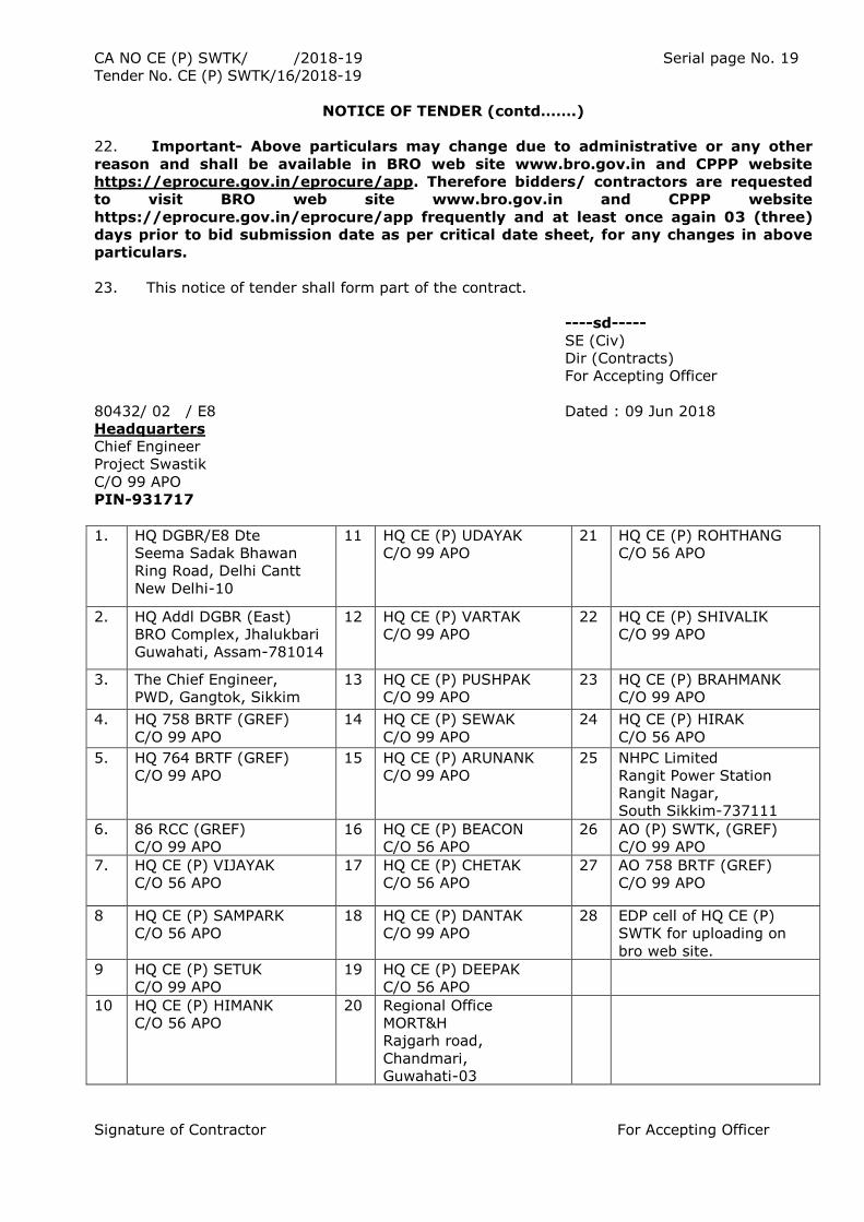
22. Important- Above particulars may change due to administrative or any other
reason and shall be available in BRO web site www.bro.gov.in and CPPP website
https://eprocure.gov.in/eprocure/app. Therefore bidders/ contractors are requested
to visit BRO web site www.bro.gov.in and CPPP website
https://eprocure.gov.in/eprocure/app frequently and at least once again 03 (three)
days prior to bid submission date as per critical date sheet, for any changes in above
particulars.
23. This notice of tender shall form part of the contract.
----sd-----
SE (Civ)
Dir (Contracts)
For Accepting Officer
80432/ 02 / E8 Dated : 09 Jun 2018
Headquarters
Chief Engineer
Project Swastik
C/O 99 APO
PIN-931717
1.
HQ DGBR/E8 Dte
Seema Sadak Bhawan
Ring Road, Delhi Cantt
New Delhi-10
11 HQ CE (P) UDAYAK
C/O 99 APO
21 HQ CE (P) ROHTHANG
C/O 56 APO
2. HQ Addl DGBR (East)
BRO Complex, Jhalukbari
Guwahati, Assam-781014
12 HQ CE (P) VARTAK
C/O 99 APO
22 HQ CE (P) SHIVALIK
C/O 99 APO
3. The Chief Engineer,
PWD, Gangtok, Sikkim
13 HQ CE (P) PUSHPAK
C/O 99 APO
23 HQ CE (P) BRAHMANK
C/O 99 APO
4. HQ 758 BRTF (GREF)
C/O 99 APO
14 HQ CE (P) SEWAK
C/O 99 APO
24 HQ CE (P) HIRAK
C/O 56 APO
5.
HQ 764 BRTF (GREF)
C/O 99 APO
15 HQ CE (P) ARUNANK
C/O 99 APO
25 NHPC Limited
Rangit Power Station
Rangit Nagar,
South Sikkim-737111
6.
86 RCC (GREF)
C/O 99 APO
16 HQ CE (P) BEACON
C/O 56 APO
26 AO (P) SWTK, (GREF)
C/O 99 APO
7. HQ CE (P) VIJAYAK
C/O 56 APO
17 HQ CE (P) CHETAK
C/O 56 APO
27 AO 758 BRTF (GREF)
C/O 99 APO
8 HQ CE (P) SAMPARK
C/O 56 APO
18 HQ CE (P) DANTAK
C/O 99 APO
28 EDP cell of HQ CE (P)
SWTK for uploading on
bro web site.
9 HQ CE (P) SETUK
C/O 99 APO
19 HQ CE (P) DEEPAK
C/O 56 APO
10 HQ CE (P) HIMANK
C/O 56 APO
20 Regional Office
MORT&H
Rajgarh road,
Chandmari,
Guwahati-03
Signature of Contractor For Accepting Officer
CA NO. CE (P) SWTK/ /2018-19 Serial Page No 20 to 61
Tender No. CE (P) SWTK/16/2018-19
GENERAL CONDITIONS OF CONTRACTS
(IAFW-2249): LATEST EDITION
FOR
LUMP SUM CONTRACTS (IAFW-2159) REVISED 1947
Name of Work : DESIGN AND CONSTRUCTION INCLUDING SUBSOIL INVESTIGATION
OF 130 MTR LONG (OUTER TO OUTER) MAJOR PERMANENT BRIDGE ON OPEN
FOUNDATION WITH PSC BALANCED CANTILEVER TYPE SUPERSTRUCTURE WITH
ABUTMENT OVER LACHUNG CHU RIVER AT KM 0.650 ON ROAD LACHUNG-ZEKUPHYAK-
KATAO UNDER PROJECT SWASTIK IN SIKKIM STATE
1. A copy of the GENERAL CONDITIONS OF CONTRACTS IAFW-2249 (Latest edition).
I/we have read and understood the provisions contained in the aforesaid General Conditions of
Contracts before submission of the tender and I/we agree that I/we shall abide by the terms and
conditions thereof.
2. It is hereby further agreed and declared by me/us that the General Conditions of
Contracts IAFW-2249 (Latest Edition) including condition 70 thereof pertaining to
settlement of disputes by arbitration, (including all errata and Amendments thereto shall form
part of these tender documents).
3. Wherever the phrases Commander Works Engineer (CWE) and Garrison Engineer (GE)
have been used in the General Conditions of Contract IAFW-2249 (Latest Edition) the
same are considered as Commander Contract and OC Contract respectively as applicable in
Border Roads Organisation.
Note:Copy of General conditions of contracts IAFW-2249 (Latest Edition) can be
referred in any office of BRO.
Signature of Contractor For Accepting Officer
CA NO. CE (P) SWTK/ /2018-19 Serial Page No 62
Tender No. CE (P) SWTK/16/2018-19
SPECIAL CONDITIONS
1. GENERAL
The following Special Conditions shall be read in conjunction with the General Conditions
of Contract, IAFW-2249 and IAFW-2159 including errata/ amendments thereto. If any provision
in these special conditions is at variance with that of the aforesaid documents, the former shall
be deemed to take precedence there over.
The special conditions given in succeeding paragraphs shall be read in conjunction with
Schedule-A, technical specifications and General Conditions of Contracts IAFW -2249. In case of
any discrepancies in the various provisions of the contract, the following order of precedence
shall be observed:-
a. Description in Schedule „A‟
b. Particular/Technical specifications
c. Ministry of Road Transport & Highways (MoRT&H) specifications for Road and
Bridge works (latest revision) published by Indian Roads Congress N. Delhi
d. Drawing and sketches
e. Special conditions
f. General conditions of contracts
2. INSPECTION OF SITE
2.1 The contractor is advised to inspect the site(s) of work by making prior
appointment with Commander 758 BRTF, C/O 99 APO, Officer Commanding, 86 RCC
(GREF), C/O 99 APO so as to acquaint himself with regard to the nature and conditions of
site, nature and means of local communication, working hours, conditions of access and
all other cognate matters concerning the execution and completion of the work. Any
paths, tracks, approaches etc required for the movement of plants, equipments, machines
and vehicles etc to the work site and platform, bund etc required for the execution of work
will be the responsibility of the contractor and rates quoted must include these aspects
also where required. The tenderer shall be deemed to have inspected the site and made
himself familiar with various factors which may affect his quotation whether he actually
inspects the site or not. No extra charges consequent on misunderstanding or otherwise
will be allowed.
2.2 The contractor shall be deemed to have fully inspected and made himself familiar with
various factors which may affect his quotation whether he actually inspects the site or
not. No extra charges consequent on any misunderstanding or other otherwise shall be
allowed.
2.3 The contractor shall be deemed to have fully become conversant with the local
conditions prevailing in the J&K State where the contract is operative e.g. restrictions of
plying of the vehicles imposed by the Security Forces and/or local administration and/or
law enforcing agencies and also the liabilities for the security checks etc. The department
will not be responsible for the eventualities due to security risks/ security requirements as
may be required and/or imposed by the security forces and/or by the local administrative
and/or law enforcing agencies. No claim whatsoever on this account shall be admissible.
Signature of Contractor For Accepting Officer CA
CA NO. CE (P) SWTK/ /2018-19 Serial Page No 63
Tender No. CE (P) SWTK/16/2018-19
SPECIAL CONDITIONS (Contd…..)
3. LAND FOR OFFICES ETC
The contractor shall have to make his own arrangements for land as may be required by
him for housing of staff and labour and for erection of stores sheds, office, godowns etc. The
Contractor must ensure that the staff, labour, plants, equipment & stores etc. employed or
collected in connection with the work are so located that there is no hindrance to the free flow of
the traffic on the highway. Suitable warning boards, lights and other measures are to be
provided by the contractor at his own cost, for safety of the traffic.
4. MINIMUM FARE WAGES PAYABLE TO LABOURERS
(a) The contractor shall pay wages not less than the fair wage fixed from time to time
by the State Govt. or minimum wages fixed under the Minimum Wages Act by Central
Govt. whichever is higher. He shall have no claim whatsoever, if on account of any local
regulations or otherwise he is required to pay wages in excess of the wages so fixed.
However, for the calculation of escalation payment, value of L1 & Lo will be considered on
minimum wages fixed under Minimum Wages Act.
(b) The contractor shall observe the Laws/Rules Regulations of Govt. of Sikkim
regarding the employment of labour, mode of payment of wages and cognate matters
relating to the local conditions.
(c) In case local labourers are not available, the contractor may have to obtain written
permit from appropriate authority of Govt of Sikkim to import labour from outside the
State.
(d) The contractor shall ensure compliance to all the labour wages laws and benefit
rules for the labour employed by him.
(e) The cpontractor shall maintain muster roll of all labour engaged in the work
alongwith wages being paid to labour (trade wise). The muster roll shall be available at
site for inspection by Engineer-In-Charge or any authorized Govt officials.
5. ROYALTIES:
(a) Reference condition 14 of General Conditions of Contracts (I.A.F.W 2249). No quarries
on charge of department are available. The contractor shall make his own arrangements
for obtaining/quarrying sand/stone & obtaining other materials required for the work.
Payment of royalties of such materials is to be borne by the Contractor, and his quoted
rates shall be deemed to include for the same.
(b) If contractor himself is primary license holder of quarry/miners than he shall submit
the royalty payment certificate as per specimen given hereunder, since he himself pays
the royalty to concerned state deptt. In addition to royalty payment certificate he shall
also submit the vehicle wise challan for transit of materials. These documents shall be
sent to mining deptt for information and verification at their end.
Royalty payment certificate
It is certified that I/We, M/s __________________________(Primary License Holder as
well as contractor) having a license No __________ issued by Forest/Mining Department,
Government of ___________________have supplied the following materials aginst CA No
CE (P) / TF Cdr ____________during the period from ______________________to
_______________.
Sr No Materials Quantity supplied.
It is further certified that Royalty etc for the above quantity of materials at applicable
rates have been paid by us to the concerned department of the Government of
___________________. A copy of No demand certificate/Challan/Permit/Affidavit duly
verified by the concerned department etc is enclose herewith.
M/s __________________________
(Primary License Holder as well as contractor)
Signature of Contractor For Accepting Officer
CA NO. CE (P) SWTK/ /2018-19 Serial Page No 64
Tender No. CE (P) SWTK/16/2018-19
SPECIAL CONDITIONS (Contd…..)
(c) If contractor is purchasing materials from primary license holders /secondary sources
then royalty payment certificate shall not be insisted upon the contractor, since he does
not pay royalty directly to the state deptt. In such cases following documents shall be
obtained :-
(i) Purchase voucher (original purchase voucher shall be defaced by the Engineer-
in-Charge /OC under his dated signature stating “verified against CA NO ……..so as
to avoid these being used again. CTC of Defaced purchase voucher shall be kept on
record.
(ii) Vehicle wise challan for transit of materials.
The above documents hall be sent to mining deptt for information/verification at their end.
(d) Since as per condition 10(A) of IAFW-2249, the contractor has to indemnify Govt for
payment of any royalty and he is primarily responsible for paying the royalty to concerned
deptt therefore if any demand of royalty is received from concerned deptt at any time
after verification of above documents, the contractor shall pay the same to concerned
state deptt. Undertaking to this effect shall be given by the contractor before receiving
any payment.
(e) Receipt of confirmation of verification of documents sent to mining deptt shall not be
mandatory before making payment to contractor, unless there are statutory
order/instructions in any state that verification of payment of royalty is mandatory.
(f) Dispatch details of all intimations/documents sent to concerned State Govt.
Authorities shall be properly kept in record and should be readily available with the
respective unit of BRO.
6. BLASTING ROCKS
(a) The contractor shall be responsible for the safe custody and storage of blasting
materials in accordance with the rules on the subject. Written authority of the OC
contract shall be obtained before any blasting operations are commenced.
(b) The contractor shall ensure that the charges in blasting are not excessive and that
the charged bore holes are properly protected before firing and that proper precautions
are taken for the safety of men and property.
(c) Blasting should be generally avoided. In case it is unavoidable less charge
controlled blasting may be resorted with the prior permission of the Engineer-in-Charge.
The contractor shall be bound to abide by the instructions of the OC contract regarding
the necessity of blasting and the type, number size and pattern of holes to be drilled and
also the type, amount and method of firing of explosive to be used. The OC contract shall
reserve the right to restrict the number of charge to be fired at a time so that the hillside
is not adversely affected. The contractor shall fire the charges only at such time as
approved by the OC contract and shall have no claim, whatsoever, on account of any
delay and extra cost due to carrying out the instructions of the OC contract and/or taking
the safety precautions directed by him.
7. MOVEMENT OF CONTRACTOR‟S VEHICLES
7.1 Minimum classification of existing bridges on the roads are Class 18R bridges,
contractor should not bring any heavier vehicle/plant/equipment as such
vehicle/plant/equipment shall not be allowed on the bridges. The contractor's vehicle may
be required to ply in convoys as per directions given by the concerned Civil/Military
authorities. No extra payment/time will be admissible on this account.
7.2 In case the condition of these bridges warrant further downward load classification
due to any unforeseen circumstances, the same will be done by the OC Contract whose
decision shall be final and binding. In case of any such eventuality, the contractor may
have to unload his heavy load carried at locations, indicated to suit the load classification
indicated by the OC Contract. Any such heavy load carriage thus necessitated across such
indicated bridge(s) shall have to be done by the contractor without any additional
payment and no claim whatsoever on this account will be entertained
Signature of Contractor For Accepting Officer CA
CA NO. CE (P) SWTK/ /2018-19 Serial Page No 65
Tender No. CE (P) SWTK/16/2018-19
SPECIAL CONDITIONS (Contd…..)
8. SECURITY RESTRICTIONS
8.1 Contractor shall employ only Indian National after verifying their antecedents and
loyalty. The contractor shall on demand by the EIC/OC Contract , submit list of his agents,
employees and work people concerned and shall satisfy the EIC/OC Contract as to the
bonafide credential of such people.
8.2 The contractor and his workmen shall observe all the rules promulgated by the
authority controlling the area in which work is to be carried out e.g. prohibition of
smoking, lighting fire precautions, search of persons on entry and exit, keeping to
specified routes and transport may be conducted by the departmental authorities at the
site of works at any time and any number of times for security reasons. Necessary permits
are to be obtained from Civil authorities by the contractor, for himself, his staff and
labour. Nothing shall be paid extra on this account.
8.3 Necessary assistance will be extended to the contractor by the department for
providing passes/permits to the contractor, his representatives and workmen to enter the
state8. Supply of Railway Wagons
9. FREE ACCESS TO SITES AND LOOKING AFTER OF WORKS
The contractor shall give all reasonable facilities to this department personnel for the
inspection of the works being executed under this contract. He will also provide free
access to the works if being executed by this department or other agencies and if such
works are located near the sites covered under this contract. Responsibility of all the
works covered in this contract will lie on the contractor and these works will be fully
completed and accordingly handed over to this department.
10. TAXES ETC
The tendered amount shall, inter-alia be deemed to be inclusive of all taxes viz. Goods
and Services Tax applicable in Sikkim, Work Contract Tax ,Terminal taxes, Toll taxes,
Royalty, Octroi, labour welfare cess, sales tax/VAT, Service Tax, Monopoly charges, and
other taxes and the like levies payable under the respective existing states etc. No claim
on account of any taxes will be payable to contractor whatsoever except as provided in
sub para 11 (b) here-in-after.
11. RE-IMBURSEMENT/REFUND ON VARIATION IN “TAXES DIRECTLY RELATED TO
CONTRACT VALUE
(a) The rates quoted by the contractor shall be deemed to be inclusive of all taxes
(including GST on materials, GST on Works Contracts, Turnover Tax, Service Tax, Labour
Welfare Cess/Tax Ecological and Environment Cess etc), duties, Royalties, Octroi & other
levies payable under the respective statutes. No re-imbursement/refund for variation in
rates of taxes, duties, royalties, Octroi & other levies, and/or imposition/abolition of any
new/existing taxes, duties, Royalties, Octroi & other levies shall be made except as
provided in sub para (b) here-in-below.
(b) (i) The taxes which are levied by Govt at certain percentage rates of Contract
Sum/Amount shall be termed as “taxes directly related to contract value” such as GST on
works contracts, Turnover Tax, Labour Welfare Cess/Tax and like but excluding Income
Tax. The tendered rates shall be deemed to be inclusive of all “taxes directly related to
contract value” with existing percentage rates as prevailing on last due date for receipt of
tenders. Any increase in percentage rates of “taxes directly related to contract value”
with reference to prevailing rates on last due date for receipt of tenders shall be refunded
by the contractor to the Govt/deducted by the Govt from any payments due to the
contractor. Similarly imposition of any new “taxes directly related to contract value” after
the last due date for receipt of tenders shall be reimbursed to the contractor and abolition
of any “taxes directly related to contract value” prevailing on last due date for receipt of
tenders shall be refunded by the contractor to the Govt/deducted by the Govt from the
payments due to the contractor
Signature of Contractor For Accepting Officer CA
CA NO. CE (P) SWTK/ /2018-19 Serial Page No 66
Tender No. CE (P) SWTK/16/2018-19
SPECIAL CONDITIONS (Contd…..)
(ii) The contractor shall, within a reasonable time of his becoming aware of variation in
percentage rates and/or imposition of any further “taxes” directly related to contract
value”, give written notice thereof to the OC Contract stating that the same is given
pursuant to this Special Condition, together with all information relating there to which he
may be in a position to supply. The contractors shall submit the other documentary
proof/information as the OC Contract may required.
(iii) The contractor shall, for the purpose of this condition keep such books of account
and other documents as are necessary and shall allow inspection of the same by a duly
authorized representative of Govt, and shall Further, at the request of the OC Contract
furnish, verified in such a manner as the OC Contract may require, any documents so kept
and such other information as the OC Contract may require.
(iv) Reimbursement for increase in percentage rates/imposition of “taxes directly
related to contract value” shall be made only if the contractor necessarily & properly pays
additional “taxes directly related to contract value” to the Govt, without getting the same
adjusted, against any other tax liability or without getting the same refunded from the
concerned Govt Authority and submits documentary proof for the same as the OC
Contract may require”.
Note:- The word Goods & Service Tax (GST) in the above clause includes Central
Goods & Service Tax (CGST), State Goods & Service Tax (SGST), Union Territory
Goods & Service Tax (UTGST) and Integrated Goods & Service Tax (IGST) all as
applicable.
12 SECURITY OF DOCUMENTS
The contractor shall not communicate any classified information regarding
works/organization either to the sub contractor or others without prior approval of the
EIC. Any violation on this aspect will be forfeit the right of the contractor to claim any
amount due to the contractor whatsoever held with organization.
13. FOREIGN EXCHANGE/IMPORT LICENSE
No foreign exchange and/or import license will be arranged by the Department in
connection with the work under this contract.
14. CONTRACTOR‟S PLAN/EQUIPMENT AT SITE
(a) The contractor shall furnish to the Engineer-in-Charge a distribution return of his
plant/equipment on the site of works, stating the following particulars: -
i) Particulars of Plant/equipment i.e. Make, Manufacture‟s No, Model No, if
any, Registration No, if any, capacity, year of manufacture, year of
purchase etc.
ii) Total quantity on site of work.
iii) Location indicating quantity at the site of work.
(b) For the purpose of this condition, plant/equipment shall include vehicles, trucks
and Lorries but not the workmen‟s tools and/or any manually operated tools/equipment.
(c) The Engineer-in-Charge shall record the particulars supplied by the contractor as
aforesaid, in the works diary and send a return to OC Contract for record in his office.
(d) The first return shall be submitted immediately after any plant or equipment is
brought to the site. Thereafter every week changes in the return shall be furnished in the
following form: -
S/No Particulars of
plant/ equipment
Total No at site
of work
Location Remarks
Addition Since………………….
Reduction Since………………..
Signature of Contractor For Accepting Officer
CA NO. CE (P) SWTK/ /2018-19 Serial Page No 67
Tender No. CE (P) SWTK/16/2018-19
SPECIAL CONDITIONS (Contd…..)
(e) A complete return showing the upto-date position of plant/equipment at site shall be
submitted on 15th of every month till the works are completed and the site cleared.
(f) The contractor‟s attention is invited to condition 34 of General Conditions of Contracts
according to which no tool, plant/equipment shall be removed off the site without written
approval of the OC Contract.
15. FIXING OF PERMANENT AND TEMPORARY BENCH MARKS: Pmt bench mark be fixed
at any nearby safe location or considered from any existing permanent building. RL be
transferred and TBM be fixed at an interval of appx 200 mtr along the existing alignment at safe
place. These temp BM should remain intact till completion of the work.
16. TOTAL STATION EQPT: The total station eqppt with its accessories be provided by the
contractor and will remain at site till completion of job.
17. MOBILISATION ADVANCE (Applicable only for contracts with contract agreement
amount exceeding Rs 25 Crore):-
(a) Mobilisation advance shall be restricted to 10% of Contract Agreement amount.
(b) Applicable in cases, where the total amount of mobilization advance does not exceed `
500 Lakh.
Mobilization Advnce against non-Revokable Bank Guarantee.
(i) Interest bearing mobilization advance restricted to 10% of Contract Agreement
amount shall be given to the contractor if he so desires and on his specific written request
on production of non-revokable Bank Guarantee(s) for the corresponding amount on an
approved form of scheduled Bank. The Bank Guarantee(s) shall indemnify the Govt.
Against non- refund of mobilization advance and also against default on contractors part
in performance of the contract. The rate of interest shall be 10% per annum simple
interest.
(ii) The mobilization advance shall be paid to the contractor within 30 days of
acceptance of the Bank Guarantee(s) furnished by him, by Accepting Officer. The amount
of mobilization advance together with interest shall be recovered from the payments made
to the contractor against “ Advance on Account”, under condition 64 of IAFW-2249,
General Conditions of Contracts.
(iii) The amount of mobilization advance shall be recovered in suitable number of equal
monthly instalments as stipulated here after. The first installment of recovery shall be
effected from the „Advance on Account‟ payment made immediately following the payment
of mobilization advance and the last installment of recovery shall be effected during the
fourth month preceding the month in which the due date of completion stipulated in the
first work order falls.
(iv) The contractor shall furnish a number of Bank Guarantees equal to number of
installations for recovery, each to match the quantum of recovery to be effected from the
„Advance on Account‟. In case, recovery is not possible to be effected from any particular
„Advance on Account‟ for reasons of non submission of claim for payment of „Advance on
Account‟ any other reason whatsoever, the recovery due shall be made by encashing the
Bank Guarantee.
(c) Applicable in cases where the Total amount of mobilization advance exceeds for Rs.
500 lac.
“Mobilization Advance against non–revokable Bank Guarantee.
Signature of Contractor For Accepting Officer
CA NO. CE (P) SWTK/ /2018-19 Serial Page No 68
Tender No. CE (P) SWTK/16/2018-19
SPECIAL CONDITIONS (Contd…..)
(i) Interest bearing mobilization advance restricted to 10% of Contract Agreement
amount shall be given to the Contractor if he so desires and on his specific written
request, in two installments, on production of non-revokable Bank Guarantee(s) on an
approved from a schedule Bank. The Bank Guarantee(s) shall indemnify the Government
against non–refund of mobilization advance and also against default on contractor‟s part
in performance of the Contract. The rate of interest shall be 10% per annum simple
interest.
(ii) The first installment of mobilization advance shall be 50% of advance and shall be
paid to the contractor by Accepting Officer within 30 days of acceptance of Bank
Guarantee(s) of 110% of the same amount furnished by the contractor. The second
installment of the balance amount shall be paid to the contractor after submission of proof
of utilization of 1st installment and within 30 days of acceptance of Bank Guarantee(s) of
110% of the same amount furnished by the contractor.
(iii) The total amount of mobilization advance together with interest shall be recovered
from the payments made to the Contractor against “ Advances on Account”, under
condition 64 of IAFW-2249, MES General Conditions of contracts.
(iv) The amount of mobilization advance shall be recovered in monthly **/fortnightly
installments as stipulated hereinafter.
**Delete whichever is inapplicable.
(aa) Against the first installment of mobilization advance of Rs. 500 lakhs, the first
installment of recovery shall be effected from the „Advance on Account‟ payment made
immediately following the payment of mobilization advance of Rs. 500 lakhs and the last
installment of recovery shall be effected during the fourth month preceding the month in
which the due date of completion stipulated in first Work Order falls. The various
installments of recovery shall be equal amounts.
(bb) Against the second installment of mobilization advance, the first installment or
recovery shall be effected from the „Advance on Account' payment made immediately
following the payment of mobilization advance of second installment and the last
installment of recovery shall be effected during the fourth month preceding the month in
which the due date of completion stipulated in first Work order falls. The various
installments of recovery shall be equal amounts. The recovery in installments of this
mobilization advance shall be of in addition to recovery in installment of the mobilization
advance of first installment.
(v) The Contractor may furnish one Bank Guarantee or a number of Bank
Guarantee(s) equal to number of installments for recovery, each to match the quantum of
recovery to be effected from the „ Advance on Account‟. In case recovery is not possible
to be effected from any particular „Advance on Account‟ for reasons of non-submission of
Claim for payment of „Advance on Account‟ or for any other reasons whatsoever, the
recovery due shall be made by encashing the Bank Guarantee”.
(d) Advance mobilization Guarantee format will be followed as updated format Form DPM-
16 prescribed by MoD in Defence procurement Manual (present format enclosed at
annexure I to special conditions (tender page no 108). The authenticity of such BGs shall
also be invariably verified from the issuing bank, confidentially and independently by the
organization.
(e) There shall be a 15% interest charged on delayed recoveries either due to the late
submission of bill by the contractor or any other reason besides the reason giving rise to
the encashment of Bank Guarantee as stated above.
(f) Utilization certificate from the contractor for the mobilization advance.
Signature of Contractor For Accepting Officer
CA No. CE (P) SWTK/ /2018-19 Serial Page No 69
Tender No. CE (P) SWTK/16/2018-19
SPECIAL CONDITIONS (Contd…..)
18. FOSSILS :
18.1 All fossils, coins, articles of value or antiquity, and structures and other remains or
items of geological or archaeological interest found on the Site shall be placed under the
care authority of the contractor shall take reasonable precautions to prevent Contractor‟s
Personnel or other persons from removing or damaging any of these findings.
18.2 The Contractor shall, upon discovery of any such findings, promptly give notice to
the Engineer-in-Charge/OC Contract, who shall issue instructions for dealing with it. If the
Contractor suffers delay and/or incurs Cost from complying with the instructions, the
Contractor shall give a further notice the Engineer-in--Charge/OC Contract describing in
detail the delay sustained by him and cost measured by him for following the instructions
of the Engineer-in Charge/OC Contract in dealing with the fossils along with all supporting
documents/proof, within 7 days of the occurrence. The Contractor then be certified for the
following:-
(a) an extension of time for any such delay, If completion is or will be delayed due to such
act in following the instructions of the Engineer-in-Charge/OC Contract.
(b) payment of any such Cost, which shall be included in the Contract Price.
18.3 After receiving this further notice, the Engineer-in-Charge/OC Contract shall examine
the case with facts and figures and disagreements if any will be communicated to the
contractor.
18.4 In case of any disputes, the matter shall be referred to the Accepting Officer whose
decision shall b e final and binding.
19. TIMES AND PROGRESS CHART
(a) The time and progress chart to be prepared as per General Conditions of Contracts
shall consist of detailed network analysis and a time schedule. The critical path network
will be drawn jointly by the OC Contract and the contractor soon after acceptance of the
tender. The time scheduling of the activities including a net work for all preliminary
arrangements for mobilization of resources e.g. manpower, plant & machinery will be
done by the contractor, so as to complete the work within the stipulated time.
(b) On completion of the time schedule a firm calendar date schedule will be prepared
and submitted by the contractor to OC Contract who will approve it after due scrutiny. The
schedule will be submitted in quadruplicate within six weeks from the date of handing
over the site.
(c) During the currency of the work the contractor is expected to adhere to the time
schedule and this adherence will be a part of the contractor‟s performance under the
contract. During the execution of the work the contractor is expected to participate in the
review and updating of the net work undertaken by OC Contract. These reviews may be
undertaken at the discretion of the OC Contract either as periodic appraisal measures or
when the quantum of work ordered on the contractor is substantially changed through
deviation orders or amendments. Any revision of the schedule as a result of the review
will be submitted by the contractor to the OC Contract within a week who will approve it
after due scrutiny. The contractor will adhere to the revised schedule thereafter. In case
of the contractor‟s not agreeing to the revised schedule the same will be referred to the
Accepting Officer whose decision will be final, conclusive and binding. OC‟s approval to
the revised schedule resulting in a completion date beyond the stipulated date(s) of
completion shall not automatically amount to grant of extension of time. Extension of
time shall be considered and decided by the appropriate authority mentioned in condition
11 of IAFW-2249 General Conditions of Contracts and separately regulated.
Signature of Contractor For Accepting Officer
CA No. CE (P) SWTK/ /2018-19 Serial Page No 70
Tender No. CE (P) SWTK/16/2018-19
SPECIAL CONDITIONS (Contd…..)
(d) The contractor is expected to mobilize and employ sufficient resources to achieve
detailed time schedule within the broad frame work of the accepted methods of working
and safety.
(e) No additional payments will be made to the contractor for any multiple shift work
or other incentive methods contemplated by him in his work schedule even though the
time schedule is approved by the department.
20. PERMIT FROM LOCAL AUTHORITIES FOR PLYING VEHICLES
Contractor shall make his own arrangements for obtaining necessary permit from local
authorities for plying his vehicles for the work in accordance with the Rules and Regulations of
the land.
21. ELECTRICITY AND WATER SUPPLY
No electricity or water will be supplied by the Department. The Contractor shall make his
own arrangement for execution of the work.
22. RATE QUOTED
(a) Unit rates shall be deemed to include the provisions for all materials, stores, labour,
process, operations and requirements detailed in particular specifications irrespective of
whether these appear as specific items or not in the Schedule “A”.
(b) Unit rates quoted shall also deemed to include all charges/expenses on account of all
Veh/Eqpts required for completing the work as specified in Schedule “A” , Goods and
Services Tax applicable in Sikkim, Sales Tax, Service Tax, Work Contract Tax, Octroi,1%
labour welfare cess, Royalty, stacking of materials, inter state barrier charges or any other
charges which are required for completion of work as per Schedule “A”/ Work Order.
(c) The rate quoted shall also include transportation of materials upto work site/dumping
site including loading/unloading charges.
23. APPOINTMENT OF ARBITRATOR –IN CASE OF CONTRACT AGREEMENTS TO BE
EXECUTED BETWEEN BRO AND GOVT OF INDIA UNDERTAKING/ENTERPRISES
In the event of any dispute or difference between the parties hereto, such dispute of difference
shall be resolved amicably by mutual consultation or through the good offices of empowered
agencies of the Government. In the event of any such dispute or differences relating to the
interpretation and application of the provisions of contracts where such resolution is not possible
then the unresolved dispute or differences shall be referred by either party to the Arbitration of
one of the Arbitrators in the department of Public Enterprises to be nominated by the Secretary
to the Government of India in charge of the Bureau of Public Enterprises, and in such case the
Arbitration and Conciliation Act shall not be applicable to the arbitration under this clause.
The award of the Arbitrator shall be binding upon both the parties in the dispute. Provided,
however any party, aggrieved by such award, may make a further references for setting aside or
revision of the award to the Law Secretary, Department of Legal Affairs, Ministry of Law &
Justice, Got of India. Upon such reference the dispute shall be decided by the Law Secretary or
the Special Secretary/Additional Secretary when so authorized by the Law Secretary, whose
decision shall bind the parties finally and conclusively. The parties to the dispute will share
equally the cost of arbitration as intimated by the Arbitrator.
Signature of Contractor For Accepting Officer
CA NO. CE (P) SWTK/ /2018-19 Serial Page No 71
Tender No. CE (P) SWTK/16/2018-19
SPECIAL CONDITIONS (Contd…..)
24. MEASUEMENTS
Measurements pertaining to the work completed under this contract will be recorded and
signed in the measurement book (IAFW-2261) by the Junior Engineer after taking into account
that the required laboratory tests have been done as per the limits stipulated and as per the
frequencies laid down in the “Particular Specifications” of this contract Agreement and MORT&H
specification for road and Bridge Works (latest revision) and connected thereof and test results
are found satisfactory and proper records are maintained.
(a) The measurement recorded by Junior Engineer shall be 100% checked and signed by
the Engineer-in-Charge.
(b) 25% test check will be carried out by OC Contract on each day of measurement by the
Engineer-in-Charge.
(c) 5% test check will be carried out by the Cdr Task Force before making payment to the
contractor.
(d) The measurement should also be signed by the contractor as token of acceptance of
the measurement.
(e) In case of discrepancies in arriving out work done details, the decision of the Accepting
Officer will be final and binding for both parties.
25. ACCEPTANCE OF WORK DONE
The Engineer-in-Charge/ OC contract shall exercise control over the quality of materials
and work done by carrying out tests for the specified properties as per frequencies given in
particular specifications and specifications of MORTH (Ministry of Road Transports and Highways)
for roads and bridge latest revision.
26. RE-IMBURSEMENT/REFUND ON VARIATION IN PRICES-WAGES OF LABOUR
(THIS SUPERSEDES CONDITION 63 OF IAFW-2249) (This Special condition is
applicable only in contracts having original completion period more than 18 months)
Increase or decrease in prices consequent on variation in wages of labour shall be
adjusted on the basis stipulated hereinafter irrespective of the actual variation in price wages of
labour to the contractor :-
LABOUR
The labour component for the work under the contract as a whole shall be taken as KL of
the value of the work executed under the contract. Variation in labour wages shall be worked out
by adopting the following formula :-
EL = KL x Vg1 x (L1 – LO)
100 L0
Where –
EL = Variation in wages of labour re-imbursement to be made to the contractor or
refund to be made by the contractor.
KL = Constant representing the percentage cost of labour element as compared to the
total value of the work under the contract as a whole. The value of KL for the
work shall be 20 (Twenty)
Vg1 = Gross value of work done at contract rates during the period of reckoning less
value of work paid or payable to the contractor based on actual cost (e.g. star
rate(s), work executed under prime cost sum etc) during the period of
reckoning.
Signature of Contractor For Accepting Officer
CA NO. CE (P) SWTK/ /2018-19 Serial Page No 72
Tender No. CE (P) SWTK/16/2018-19
SPECIAL CONDITIONS (Contd…..)
L1 = Minimum wages in rupees of an unskilled adult male mazdoor as fixed under
Minimum Wages Act, as on the date of commencement of the period of
reckoning.
LO = As for L1 but the minimum wages as fixed under Minimum Wages Act in rupees
of an unskilled adult male mazdoor as on the actual date of opening of price Bid
(Part „Q‟) of tender.
Notes:
1. The contract shall within reasonable time of his becoming aware of any alteration to the
rate of wages of labour consequent on fixation of minimum wages under Minimum Wages Act,
give written notice thereof to the OC Contract stating that the same is given pursuant to this
special condition together with all information relating thereto which he may be in a position to
supply.
2. Irrespective of the variations in minimum/fair wages for any category of labour; for the
purpose of adjustment under this special condition, the variation in minimum wages fixed under
Minimum Wages Act, for an unskilled adult mazdoor, if any, shall only form the basis.
3. Periodicity of working out the variation in wages of labour will be three months
commencing from the actual date of opening of Price Bid (Part „Q‟) of tender, the last adjustment
for variation in wages of labour shall, however, be done for the period up to the stipulated date of
completion given in the first work order, or extended date of completion. Valuation of price
adjustment due to increase/decrease in minimum wages under Minimum Wages Act, for the
purpose of making reimbursement /refund in RARs, will be timed in such a manner that relevant
data required for quarterly calculation under this special condition is available from the RARs.
The first price adjustment in respect of variation in wages of labour will be worked out for the
relevant quarter during which the variation took place. For implementing this provision, the
period of reckoning in such quarter will be divided into two period, i.e. the first period upto the
RAR payable immediately after the date of variation and the other upto the end of the quarter.
Value of L1 at the beginning of the other period shall be altered minimum wage. If there are
more than one change(s) in wages in a quarter, there will be more than two periods of reckoning
on similar basis. Amount payable relevant to work done for any quarter will be worked out after
the minimum wages of an unskilled adult male mazdoor as fixed under Minimum Wages Act for
the relevant quarter is available. Once the amount adjustable for any quarter is worked out, the
same shall be adjusted in subsequent RAR as “advance on account” adjustments.
4. No adjustments in prices shall be made for any work done after the stipulated date of
completion given in the first work order or extension of time granted under condition 11 of IAFW-
2249 (whichever is later) for the work under this contract.
5. No adjustment, whatsoever, due to variation in wages of Labour on account of coming
into force of any fresh law or statutory rule or order as provided in Condition 63 of IAFW-2249 or
otherwise, than provided in this special condition shall be made. In short once this special
condition is operative condition 63 of IAFW-2249 stands superseded.
6. Any dispute arising out of interpretation of application of this special condition shall be
referred to the Accepting Officer whose decision shall be final and binding.
27. RE-IMBURSEMENT/REFUND ON VARIATION IN PRICES : MATERIALS & FUEL
(THIS SUPERSEDES CONDITION 63 OF IAFW-2249) (This Special condition is
applicable only in contracts having original completion period more than 18 months)
Increase or decrease in prices of materials and fuel shall be adjusted on the basis
stipulated hereinafter irrespective of the actual variation in prices (to the contractor) :-
(a) MATERIAL :
Signature of Contractor For Accepting Officer
CA NO. CE (P) SWTK/ /2018-19 Serial Page No 73
Tender No. CE (P) SWTK/16/2018-19
SPECIAL CONDITIONS (Contd…..)
(i) For cement
The cement cost component including the cost of cement issued under Schedule „B‟ in
accordance with condition 10 (B) of IAFW-2249, for the contract as a whole shall be taken
as KC % of the value of works executed under the contract, value of KC is given herein
below :-
EMC = (VMc2 – VMC1) x (C1 – CO)
CO
VMC = (KC x VG) + (VSC – VBC )
100
Where :-
EMC = Variation in price of Cement to be adjusted.
KC = Constant representing the percentage cost of cement, including Schedule „B‟ Cement, as
compared to the total value of work under the contract as a whole. The value of KC for
this work shall be 25 (Twenty five).
Vg = Gross value of work done at contract rates upto the last date of the period of reckoning.
VSC = Value of all cement lying at the site for incorporation in the work including cement
issued under Schedule „B‟ and including cement brought and paid or payable to
contractor under Prime Cost Sum and or Star Rate(s).
VBC = Value of all cement (out of VG and VSC) issued under Schedule „B‟ plus value of all
Cement brought and paid or Payable to contractor under Prime Cost Sum and/or Star
Rate(s).
C1 = Whole sale Price index for cement (Base 2004-05) published by the economic Advisor
to the Govt of India, as on date of commencement of the period of reckoning. In case
the original contract period is extended under condition-11 of IAFW-2249, the price
index as applicable on the date of commencement of last period of reckoning before the
original completion date shall only be applicable during the extended period.
CO = As for C1 but the index as on the actual date of opening of Price Bid (Part „Q‟) of tender.
VMC2 = Value of Cement upto the last date of the period of reckoning for which price variation is
adjustable as worked out as per formula for VMC.
VMC1 = -do- but as on date of immediate preceding period of reckoning.
(ii) For steel
The Steel cost component including the cost of Steel issued under Schedule „B‟ in
accordance with condition 10 (B) of IAFW-2249, for the contract as a whole shall be taken
as KS % of the value of works executed under the contract, value of KS is given herein
below :-
EMS = (VMS2 – VMS1) x (S1 – sO)
SO
VMS = (KSx VG) + (VSS – VBS )
100
Where :-
EMS = Variation in price of Steel to be adjusted.
KS = Constant representing the percentage cost of steel, including Schedule „B‟ Steel, as
compared to the total value of work under the contract as a whole. The value of KS for
this work shall be 27 (Twenty Seven).
Signature of Contractor For Accepting Officer
CA NO. CE (P) SWTK/ /2018-19 Serial Page No 74
Tender No. CE (P) SWTK/16/2018-19
SPECIAL CONDITIONS (Contd)
Vg = Gross value of work done at contract rates upto the last date of the period of reckoning.
VSS = Value of all steel lying at the site for incorporation in the work including Steel issued
under Schedule „B‟ and including steel brought and paid or payable to contractor under
Prime Cost Sum and or Star Rate(s).
VBS = Value of all Steel (out of VG and VSS) issued under Schedule „B‟ plus value of all Steel
brought and paid or Payable to contractor under Prime Cost Sum and/or Star Rate(s).
S1 = Whole sale Price index for Iron & Steel (Base 2004-05) published by the economic
Advisor to the Govt of India, as on date of commencement of the period of reckoning.
In case the original contract period is extended under condition-11 of IAFW-2249, the
price index as applicable on the date of commencement of last period of reckoning
before the original completion date shall only be applicable during the extended period.
SO = As for C1 but the index as on the actual date of opening of Price Bid (Part „Q‟) of tender.
VMS2 = Value of Steel upto the last date of the period of reckoning for which price variation is
adjustable as worked out as per formula for VMC.
VMS1 = -do- but as on date of immediate preceding period of reckoning.
(iii) For Bitumen
The Bitumen cost component including the cost of Bitumen issued under Schedule „B‟ in
accordance with condition 10 (B) of IAFW-2249, for the contract as a whole shall be
taken as KB % of the value of works executed under the contract, value of KB is given
herein below :-
EMB = (VMB2 – VMB1) x (B1 – BO)
BO
VMB = (KBx VG) + (VSB – VBB )
100
Where :-
EMB = Variation in price of Bitumen to be adjusted.
KB = Constant representing the percentage cost of Bitumen, including Schedule „B‟ Bitumen,
as compared to the total value of work under the contract as a whole. The value of KB
for this work shall be 15 (Fifteen).
Vg = Gross value of work done at contract rates upto the last date of the period of reckoning.
VSB = Value of all Bitumen lying at the site for incorporation in the work including Bitumen
issued under Schedule „B‟ and including Bitumen brought and paid or payable to
contractor under Prime Cost Sum and or Star Rate(s).
VBB = Value of all Bitumen (out of VG and VSB) issued under Schedule „B‟ plus value of all
Bitumen brought and paid or Payable to contractor under Prime Cost Sum and/or Star
Rate(s).
B1 = Monthly Whole sale Price index for Bitumen (Base year 2011-12) published by the
economic Advisor to the Govt of India, as on date of commencement of the period of
reckoning. In case the original contract period is extended under condition-11 of IAFW-
2249, the price index as applicable on the date of commencement of last period of
reckoning before the original completion date shall only be applicable during the
extended period.
Signature of Contractor For Accepting Officer
CA NO. CE (P) SWTK/ /2018-19 Serial Page No 75
Tender No. CE (P) SWTK/16/2018-19
SPECIAL CONDITIONS (Contd)
BO = As for B1 but the index as on the last date of receipt of tender.
VMB2 = Value of Bitumen upto the last date of the period of reckoning for which price variation is
adjustable as worked out as per formula for VMB.
VMB1 = -do- but as on date of immediate preceding period of reckoning.
(iii) Other Materials (Materials except cement, steel and Bitumen) : The “other
materials” cost component including the cost of “other materials” issued under Schedule
„B‟ in accordance with condition 10 (B) of IAFW-2249, for the contract as a whole shall
be taken as KM % of the value of works executed under the contract, value of KM is
given herein below :-
EM = (VM2 – VM1) x (W1 – WO)
Wo
VM = (KM x VG) + (VS – VB)
100
Where :-
EM = Variation in price of “other materials” to be adjusted.
KM = Constant representing the percentage cost of “other materials”, including Schedule „B‟
“other materials”, as compared to the total value of work under the contract as a whole.
The value of KM for this work shall be 10 (Ten).
Vg = Gross value of work done at contract rates upto the last date of the period of reckoning.
VS = Value of all “other materials” lying at the site for incorporation in the work including
“other materials” issued under Schedule „B‟ and including “other materials” brought and
paid or payable to contractor under Prime Cost Sum and or Star Rate(s).
VB = Value of all “other materials” (out of VG and VS) issued under Schedule „B‟ plus value of
all “other materials” brought and paid or Payable to contractor under Prime Cost Sum
and/or Star Rate(s).
W1 = Whole sale Price index for all commodities (Base 2004-05) published by the economic
Advisor to the Govt of India, as on date of commencement of the period of reckoning.
In case the original contract period is extended under condition-11 of IAFW-2249, the
price index as applicable on the date of commencement of last period of reckoning
before the original completion date shall only be applicable during the extended period.
WO = As for W1 but the index as on the actual date of opening of Price Bid (Part „Q‟) of tender.
VM2 = Value of “other materials” upto the last date of the period of reckoning for which price
variation is adjustable as worked out as per formula for VM.
VM1 = -do- but as on date of immediate preceding period of reckoning.
W1 = Whole sale Price index for all commodities (Base 2004-05) published by the
economic Advisor to the Govt of India, as on date of commencement of the period of
reckoning. In case the original contract period is extended under condition-11 of IAFW-
2249, the price index as applicable on the date of commencement of last period of
reckoning before the original completion date shall only be applicable during the
extended period.
WO= As for W1 but the index as on the actual date of opening of Price Bid (Part „Q‟)
of tender.
VM2= Value of materials upto the last date of the period of reckoning for which price
variation is adjustable as worked out as per formula for VM.
Signature of Contractor For Accepting Officer
CA NO. CE (P) SWTK/ /2018-19 Serial Page No 76
Tender No. CE (P) SWTK/16/2018-19
SPECIAL CONDITIONS (Contd)
VM1= -do- but as on date of immediate preceding period of reckoning.
(b) FUEL :
Fuel cost component for the contract as a whole shall be taken as KP% of the value
of work executed under the contract. Value of KP given herein below :-
EP = KP x VG1 x (F1 – FO)
100 FO
Where :-
EP = Variation in price of fuel to be adjusted.
KP = Constant representing the percentage of cost of fuel as compared to the total value
of work under the contract as a whole. The value of KP for this work shall be 03
(Three).
Vg1= Gross value of work done during the period of reckoning, using value of Vg for
calculating VM1 and VM2 under (a) above.
F1 = Whole sale price index for sub group for fuel power, light and lubricants (base
2204-05 = 100) published by Economic Adviser to Government of India as on the
date of commencement of the period of reckoning.
FO = As for F1 but the index as on the actual date of opening of Price Bid (Part „Q‟) of
tender.
NOTES :-
1. No adjustments, whatsoever, due to variation in prices of materials and fuel on account of
coming into force of any fresh law or statutory rule or order as provided in condition 63 of IAFW-
2249 or otherwise than provided in this condition shall made. In short, once this special condition
is operative condition 63 of IAFW-2249 stands superseded.
2. No adjustment in prices shall be made for any work done with materials brought at site
after the stipulated date of completion given in work order No. 1 or extension of time granted
under condition 11 of IAFW-2249 (whichever is later) for the work under the contract.
3. Periodicity of working out the variations will be at three months commencing from the
actual date of opening of price Bid (Part „Q‟) of the tender. The last calculation shall however be
done for the value of work at contract rates and materials lying at site for incorporation in the
work as on date of completion or extension thereof as mentioned in Note 2 above. Valuation of
RARs is to be timed in such a manner that relevant data required for quarterly calculation under
this condition is available from RARs. Amount payable relevant to work done and materials
collected in any quarter will be worked out after final wholesale price indices for the relevant
quarter are available. Once the amount adjustable for any quarter is worked out the same shall
be adjusted as and alongwith advance on account payment under condition 64 of IAFW-2249 in
the subsequent RAR (s).
4. Any dispute arising out of interpretation of application of this special condition shall be
referred to the Accepting Officer whose decision shall be final and binding.
5 For purpose of calculation of retention money, liquidated damages, sales tax/service tax on
works contracts, deduction of income tax at source and recovery of water charges (in case of
unmetered supply) the value of contract as revised by the above price variation will be taken
into account.
Signature of Contractor For Accepting Officer
CA NO. CE (P) SWTK/ /2018-19 Serial Page No 77
Tender No. CE (P) SWTK/16/2018-19
SPECIAL CONDITIONS (Contd)
28. RECORD/CONSUMPTION OF MAJOR CONSTR STORES/MATERIALS:
(a) (i) For the purpose of keeping a record of Major Constr Stores like Steel, cement,
Bitumen and LDO consumed in works, the contractor shall maintain a pucca bound
register in the form approved by the Engineer-In-Charge/OC Contract showing daily
quantity used in works. The register shall be signed daily by the contractor‟s
representative and the Engineer- In-Charge/OC Contract in token of their verification of its
correctness. The check will not, however, absolve the contractor of his responsibility to
justify the consumption of bitumen and LDO at the time of finalization of his work.
(ii) The register shall be kept at site in the safe custody of the contractor during
progress of the work and shall, on demand, be produced for verification of inspecting
officers.
(b) (i) The quantity of materials such a paints, water proofing compound and the like, as
directed by the Engineer-in-Charge (the quantity of which cannot be checked after
incorporation in the works), shall be recorded in measurement books and signed by the
contractor and the Engineer-In-Charge as a check to ensure that the required quantity has
been brought to site for incorporation in the work.
(ii) Materials brought to site shall be stored as directed by the Engineer-In-Charge in
measurement book and shall be suitably marked for identification.
(iii) The contractor shall, on demand produce the OC original receipted vouchers in
respect of the supplies. Vouchers so produced shall be verified and stamped by Engineer-
in-Charge indicationg contract number. The contractor shall ensure that the materials are
brought to site in original sealed containers/packing, bearing manufacturer‟s marking
except in the case of the requirement of the materials being less than smallest packing.
(iv) Contractor shall produce original vouchers from the manufactures and/or their
authorized agents for the full quantity of the following materials, as applicable as a
prerequisite before submitting for payment for any advances on account of the work
done and/or materials collected in accordance with condition 64 of general condition of
contracts IAFW-2249.
a) Bitumen.
b) Cement
c) Paint.
d) LDO
29. PAYMENT
Payment to the parties will be made in INR in the following manner:-
(a) No advance payment will be made to the contractor against any material if not
properly safeguarded against loss/damage due to natural calamities/theft.
(b) No payment shall be made for any rejected material.
(C) Taxes (Goods and Services Tax applicable in Sikkim, Income tax, service tax/sales
tax/Vat on works contracts, labour cess etc) shall be deducted at source from the
payment due to contractors as per prevailing laws/statutory orders and TDS certificate
shall be issued to the contractor.
(d) All payments will be made by e-payment/account payee cheque
Signature of Contractor For Accepting Officer
CA NO. CE (P) SWTK/ /2018-19 Serial Page No 78
Tender No. CE (P) SWTK/16/2018-19
SPECIAL CONDITIONS (Contd)
30. CO-OPERATION WITH OTHERS AGENCIES
The contractor shall permit free access and generally afford reasonable facilities to other
agencies or departmentally workmen engaged by the Govt to carry out their part of the work, if
any , under separate arrangements.
31. SUPPLY OF COLOUR RECORD PHOTOGRAPHS, ALBUMS AND VIDEO CDS :
Contractor shall provide/supply of colour record photographs, Album and video CDs at
various stages/facts of the work without any extra cost as per clause 125.1, 125.2 & 126.1 of
MORT&H specifications.
32. FIELD LABORATORY
To maintain proper quality control at site, contractor shall establish adequately equipped
field laboratory without any extra cost. He shall conduct the tests and maintain the records to be
produced with each RAR. The following minimum testing equipments shall be provided in field
laboratory:-
(i) Cube Mould for 15cm cube - 12 Nos
(ii) Compression testing machine - 01 Nos
(iii) Tensile testing machine - 01 Nos
(iv) Field laboratory for testing of aggregate & Cement, Sieve analysis test apparatus,
AIV test apparatus, Water absorption test apparatus, FI & EI test apparatus, Soundness
test apparatus, Compacting factor test apparatus, Slump test apparatus etc.
33. TRAFFIC MOVEMENT: Contractor shall ensure that no hindrance to traffic movement
shall occur during construction. However, if the traffic movement disrupt due to land slide or any
other un-foreseen reason, than contractor shall make all efforts to restore traffic movement
within time as directed by the Cdr. If contractor is unable or unwilling to restore traffic
movement, Engineer-in-charge may take action as per condition 8 of IAFW-2249. Contractor
shall immediately intimate regarding closure of the road to Engineer-In-Charge and local
administrative authorities.
34. VENUE OF ARBITRATION : The Venue of Arbitration be such a place or places as may
be fixed by the arbitrator at is his sole discretion.
35. ARBITRATION (REFER CLAUSE-70 OF CONDITIONS OF CONTRACT OF (IAFW-
2249)
All disputes or difference arising as aforementioned, other than those for which the
decision of the Accepting Officer or any other person is by the contract expressed to be final and
binding shall be referred to sole arbitrator under condition No 70 of General condition of contract
IAFW-2249 after written notice by either party of the contract to the other of them.
36. DEFECTS LIABILITY PERIOD (REFER CONDITION 46 OF IAFW-2249):
Defects liability period shall be thirty six calendar months. 2.5% of the value of work
executed shall be retained from each bill of advances on account and final bill as special security
deposit for defects liability period and shall be refund to the contractor after the expiration of
defects liability period provided always that the contractor shall first have been paid the final bill
and have rendered a No-Demand certificate (IAFA-451).
Provided further, the contractor may be paid special security deposit on his furnishing
Guarantee Bond(s) or fixed Deposit Receipt (s) from a Scheduled Bank in favor of Cdr Task Force
for the amount of the special security deposit which should otherwise be recoverable from him
under the contract.
The guarantee bond(s) or Fixed Deposit Receipt(s) shall be executed for a period and on a
form as directed by the Cdr Task Force. The Contractor shall further arrange to extend the period
of Guarantee Bond(s) or Fixed Deposit Receipt(s) or shall furnish a fresh Guarantee Bond(s) or
Fixed Deposit Receipt(s) of similar value so as to cover the period as stated above for its refund.
Special security deposit shall be in addition to security deposit specified in condition 22 of IAFW-
2249.
Signature of Contractor For Accepting Officer
CA NO. CE (P) SWTK/ /2018-19 Serial Page No 79
Tender No. CE (P) SWTK/16/2018-19
SPECIAL CONDITIONS (Contd…)
37. BILLING SCHEDULE
The pricing schedule for interim payments will be drawn up and finalized mutually
between Accepting Officer and the contractor after the acceptance of the contract. The decision
of the Accepting Officer shall be final and binding.
38. SECURITY OF CLASSIFIED DOCUMENTS
Contractor‟s special attention is drawn to conditions 2A and 3 of General Conditions of
Contracts IAFW-2249. The Contractor shall not communicate any classified information
regarding works either to sub contractors or other without prior approval of the Engineer-in-
Charge. The contractor shall also not make copies of the design/drawings and other documents
furnished to him in respect of works and he shall return all documents on completion of the
works or on earlier determination of the contract. The Contractor shall alongwith final bill attach
a receipt from the Engineer-in-Charge in respect of his having returned the classified documents
as per Condition 3 of General Condition of Contracts.
39. REGISTRATION WITH EPFO AND ESIC.
The contractor shall have registration with EPFO & ESIC. The ESI and EPF contributions on
the part of employer in respect of this contract shall be paid by the contractor. These
contributions on the part of the employer paid by the contractor shall be reimbursed by the
Commander Contract to the contractor on actual basis. Payment of contractor‟s bill will only be
released after ensuring the recovery of subscription towards EPF of labours employed by the
contractors. This amount shall be further deposited by the contractor with concerned EPF office.
40. LOSS OR DAMAGE ON ACCOUNT OF ENEMY ACTION
(a) If as a result of enemy action, the contractor suffers any loss or damage, the
Government shall reimburse to the contractor such loss or damage, to the extent and in
the manner hereinafter provided: -
(i) The loss suffered by him on account of any damage or destruction of his
plant/equipment (as defined in condition 14 (b) above) or materials or any part of
parts thereof. The amount of loss assessed by the Accepting Officer of the contract
on this account shall be final and binding.
(ii) Compensation paid by him under any law for the time being in force to any
workmen employed by him for any injury caused to him or the workmen‟s legal
successors for loss of the workmen‟s life.
(b) No reimbursement shall be made nor shall any compensation be payable under the
above provisions unless the contractor had taken Air Defence precautions ordered in
writing by OC concerned or in the absence of such orders, reasonable precautions. No
reimbursement shall be made nor shall any compensation be payable for any
plant/equipment or materials not lying on the site of work at the time of enemy action.
41. OPERATION AND MAINTENANCE INSTRUCTIONS
The contractor shall submit to the OC Contract within 2 months of actual completion, but
before final payment, operation and maintenance instructions for whole of the bridge, in
quadruplicate (bound copies).
42. ESCALATION No claim of reimbursement in increase of labour wages, cost of POL and
materials is admissible under this contract including extended period if any.
43. LEGAL JURISDICTION
Legal jurisdiction for this Contract Agreement shall be “GANGTOK, SIKKIM”
Signature of Contractor for Accepting Officer
CA NO. CE (P) SWTK/ /2018-19 Serial Page No 80
Tender No. CE (P) SWTK/16/2018-19
Annexure-1 to special conditions
FORMAT FOR BANK GURANTEE FOR ADVANCE PAYMENT
From:
Bank…………………………………………
To
The President of India
Sir,
1. With reference to contract agreement no…………………………………………..concluded between the
president of India, hereinafter referred to as “The Government” and M/s…………………………………
Hereinafter referred to as the “The Contractor” for …………………………… as detailed in the bove
contract agreement hereinafter referred to as “the said contract” and in consideration of the
Government having agreed to make an advance payment in accordance with the terms of the
said contract to the said contractor, we the ………………………………………………………….bank, hereinafter
call “the bank” hereby irrevocably undertake and guarantee to you that if the said contractor
would fail to provide works in accordance with the terms & conditions of the said conditions of the
said contract for any reason whatsoever or fail to perform the said contract in any respect or
should whole or part of the said on account payments at any time become repayable to you for
any reason whatsoever, we shall, on demand and without demur pay to you all and any sum up
to a maximum of Rs. ………………………….(Rupees…………………………………………………..only) paid as
advance to the said contractor in accordance with the provisions contained in
clause…………………………………….. of the said contract.
2. We further agree that the Government shall be the sole judge as to whether the contractor has
failed to provide works in accordance with the terms and conditions of the said contract or has
failed to perform the said contract in any respect or the whole or part of the advance payment
made to contractor has become repayable to the Government and to the extent and monetary
consequences thereof by the Government.
3. We further hereby undertake to pay the amount due and payable under this Guarantee
without any demur merely on a demand from the Government stating the amount claimed. Any
such demand made on the bank shall be conclusive and binding upon us as regards the amounts
due and payable by us under the Guarantee and without demur. However, our liability under this
Guarantee shall be restricted to an amount not exceeding Rs. ………………………..
(Rupees…………………………only)
4. We further agree that the Guarantee herein contained shall remain in full force and effect for a
period up to ……………………. (03 months + due date of recovery of advance) unless the
Government in his sole discretion discharges the Guarantee earlier.
5. We further agree that any change in the constitution of the Bank or the constitution of the
contractor shall not discharge our liability hereunder.
6. We further agree that the Government shall have that fullest liability without affecting in any
way our obligations hereunder with or without our consent or knowledge to vary any of the terms
and conditions of the said contract or to extend the time of development/delivery from time to
time or to postpone for any time or from time to time any of the powers exercisable by the
Government against the contractor and either to forebear or enforce any of the terms and
conditions relating to the said contract and we shall not be relieved from our liability by reason of
any such variation or any indulgence or for bearance shown or any act or omission on the
Government or by any such matter or thing whatsoever which under the law relating to sureties
would but for this provision have the effect of so relieving us.
7. We lastly undertake not to revoke the Guarantee during the currency of the above said
contract except with the prior consent of the Government in writing.
Yours faithfully
For ……………………………………….Bank
Place………………………….. Seal of Bank
Date…………………………
Signature of Contractor for Accepting Officer
CA NO. CE (P) SWTK/ /2018-19 Serial Page No 81
Tender No. CE (P) SWTK/16/2018-19
PARTICULAR SPECIFICATIONS
1. GENERAL
1.1 The work required to be carried out under this contract broadly comprises of the following:-
a) Setting out bench marks, centre line pillars and laying out the bridge scheme on
ground and getting it approved from the Accepting Officer.
b) Excavation of foundation upto the given foundation level, in situ test and
laboratory test of foundation strata to ascertain suitability of strata to place foundation.
Explanatory boring extending to a depth 1.5 times the proposed base width where
specified.
(c) Detailed design and preparation of detailed construction drawings, getting it proof
checked from IIT and obtaining approval thereof from Br & Tnl Dte/HQ DGBR, making
modifications as required and submission of the requisite number of copies of approved
drawings and design calculations.
(d) Construction of the bridge as per the approved design and drawings and as per
specifications mentioned hereinafter.
(e) Load testing of the superstructure of the bridge.
(f) Site clearance.
(g) Any temporary river training or river diversion works required for execution of
works. Any loss or damages to the existing structure while carrying out river training or
diversion works shall be made good by the contractor, without any extra cost to the
department.
(h) The lump sum quoted cost shall be deemed to include all costs towards all
preparatory work or any other work not specifically list but required for successful
completion of the bridge.
1.2 This contract does not include any work of approaches and approach slabs.
1.3 To cater for any change in the design requirements (other than „Clear carriage way‟ and
„load classification‟ etc) the formulae given in Annexure-I to Schedule „A‟ shall be applicable for
pricing the deviations, if ordered for the following items:-
(i) Rate per running meter increase or decrease in length of the bridge. For this
purpose length of the bridge shall be measured as the distance between centre to centre
of end bearings or distance between outer ends of the abutments in case of PSC cantilever
bridges where abutments are monolithic to superstructure.
(ii) Rate per running meter increase or decrease in height of sub structure due to
change in RL of foundation & deck level of the bridge. For this purpose, the height of
substructure shall be taken from foundation level given in the tender drawing to top of
bridge deck at crown level.
Signature of Contractor For Accepting Officer
CA NO. CE (P) SWTK/ /2018-19 Serial Page No 82
Tender No. CE (P) SWTK/16/2018-19
PARTICULAR SPECIFICATIONS (Contd….)
(iii) In case of change in type of foundation from open to well or otherwise due
to ground condition and exposed soil parameter, no extra cost will be payable. However,
variation in depth foundation with respect original one will be adjusted suitably as brought
out above.
1.4 Limit State Method of Design shall be adopted for design of various structural components
of the bridge in accordance with relevant IRC/BIS Codes and MoRTH Specifications for Road and
Bridge Works (Fifth revision).
2. LOCATION
2.1. The approximate location of the bridge is as under :-
Ser
No.
Name of the bridge Name of the
road
Distance in kms
from New
Jalpaiguri Rail
head
Remarks
(a) LACHUNG CHHU LACHUNG-
ZEKHUPHYA
K-KATAO
219.00 Km Appx
2.2 A key plan showing the location of the bridge is given in the NIT Drawing No. B-1637/
B&T Dte/Swtk/2017 Sheet No. 2RR dt 21 Feb 2017
3 SETTING OUT BENCH MARKS, CENTER LINE AND PILLARS ETC
3.1 The contractor shall layout the bridge scheme on ground and get it approved from the
Accepting Officer. Thereafter, concrete or masonry pillars indicating the exact centre line
adopted for the bridge shall be erected about 20 meters (minimum) beyond the abutments at
either end of the bridge to enable check being maintained on the centre line throughout the
period of construction. The pillars shall be of substantial section to retain their true position
during the progress of the work. The dimensions and strength of the pillars shall be adequate for
the theodolite /total station to be accommodated on them for taking readings. Sufficient number
of bench marks and other reference pillars shall be provided at suitable locations to enable
complete check being maintained on the accuracy of various levels and position. The cost of work
shall be deemed to be included in the tendered lump sum.
3.2 The Accepting Officer, due to prevailing site condition may change the site of the bridge.
In the event of his decision to change the site, the contractor shall not be entitled to any extra
payment as long as the design requirement remains unaltered. Any change in the design
requirements, whether in consequence of the change of site or otherwise, will however be treated
as deviation and its financial effect shall be worked out in accordance with the provisions made
elsewhere in the contract.
Signature of Contractor For Accepting Officer
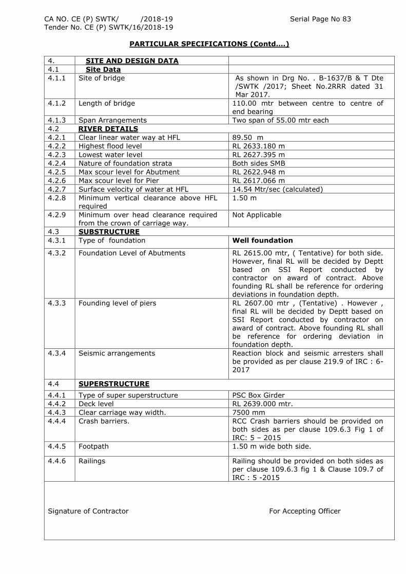
CA NO. CE (P) SWTK/ /2018-19 Serial Page No 83
Tender No. CE (P) SWTK/16/2018-19
PARTICULAR SPECIFICATIONS (Contd….)
4. SITE AND DESIGN DATA
4.1 Site Data
4.1.1 Site of bridge As shown in Drg No. . B-1637/B & T Dte
/SWTK /2017; Sheet No.2RRR dated 31
Mar 2017.
4.1.2 Length of bridge 110.00 mtr between centre to centre of
end bearing
4.1.3 Span Arrangements Two span of 55.00 mtr each
4.2 RIVER DETAILS
4.2.1 Clear linear water way at HFL 89.50 m
4.2.2 Highest flood level RL 2633.180 m
4.2.3 Lowest water level RL 2627.395 m
4.2.4 Nature of foundation strata Both sides SMB
4.2.5 Max scour level for Abutment RL 2622.948 m
4.2.6 Max scour level for Pier RL 2617.066 m
4.2.7 Surface velocity of water at HFL 14.54 Mtr/sec (calculated)
4.2.8 Minimum vertical clearance above HFL
required
1.50 m
4.2.9 Minimum over head clearance required
from the crown of carriage way.
Not Applicable
4.3 SUBSTRUCTURE
4.3.1 Type of foundation Well foundation
4.3.2 Foundation Level of Abutments RL 2615.00 mtr, ( Tentative) for both side.
However, final RL will be decided by Deptt
based on SSI Report conducted by
contractor on award of contract. Above
founding RL shall be reference for ordering
deviations in foundation depth.
4.3.3 Founding level of piers RL 2607.00 mtr , (Tentative) . However ,
final RL will be decided by Deptt based on
SSI Report conducted by contractor on
award of contract. Above founding RL shall
be reference for ordering deviation in
foundation depth.
4.3.4 Seismic arrangements Reaction block and seismic arresters shall
be provided as per clause 219.9 of IRC : 6-
2017
4.4 SUPERSTRUCTURE
4.4.1 Type of super superstructure PSC Box Girder
4.4.2 Deck level RL 2639.000 mtr.
4.4.3 Clear carriage way width. 7500 mm
4.4.4 Crash barriers. RCC Crash barriers should be provided on
both sides as per clause 109.6.3 Fig 1 of
IRC: 5 – 2015
4.4.5 Footpath 1.50 m wide both side.
4.4.6 Railings Railing should be provided on both sides as
per clause 109.6.3 fig 1 & Clause 109.7 of
IRC : 5 -2015
Signature of Contractor For Accepting Officer
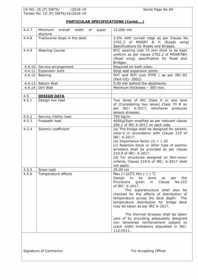
CA NO. CE (P) SWTK/ /2018-19 Serial Page No 84
Tender No. CE (P) SWTK/16/2018-19
PARTICULAR SPECIFICATIONS (Contd….)
4.4.7 Minimum overall width of super
stucture
12.000 mtr
4.4.8 Transverse slope in the deck 2.5% with curved ridge as per Clause No.
2702.3 of MOSRT & H (Roads wing)
Specifications for Roads and Bridges.
4.4.9 Wearing Course RCC wearing coat 75 mm thick to be kept
uniform as per clause 2702.2 of MOSRT&H
(Road wing) specification for Road and
Bridges.
4.4.10 Service arrangement Required on both sides.
4.4.11 Expansion Joint Strip seal expansion joints.
4.4.12 Bearing POT and POT cum PTFE ( as per IRC-83
(Part-III)- 2002)
4.4.13 Return Wall 5.00 mtr behind the abutments.
4.4.14 Dirt Wall Minimum thickness – 300 mm.
4.5 DESIGN DATA
4.5.1 Design live load Two lanes of IRC Class A or one lane
of (Considering two lanes) Class 70 R as
per IRC: 6-2017, whichever produces
severe stresses.
4.5.2 Service /Utility load 750 Kg/m.
4.5.3 Footpath load 400Kg/Sqm modified as per relevant clause
206.1 of IRC 6-2017 on each side.
4.5.4 Seismic coefficient (a) The bridge shall be designed for seismic
zone-V in accordance with Clause 219 of
IRC: 6-2017.
(b) Importance factor (I) = 1.20
(c) Reaction block or other type of seismic
arresters shall be provided as per clause
219.9 of IRC: 6-2017.
(d) For structures designed on Non-scour
criteria, Clause 219.6 of IRC: 6-2017 shall
not apply.
4.5.5 Snow load 25.00 cm
4.5.6 Temperature effects Max (+)220C Min (-) 1 0C
Design to be done as per the
Provisions given in Clause No.215
of IRC: 6-2017.
The superstructure shall also be
checked for the effects of distribution of
temperature across the deck depth. The
temperature distribution for bridge deck
may be taken as per IRC 6-2017.
The thermal stresses shall be taken
care of by providing adequately designed
non tensioned reinforcement subject to
crack width limitations stipulated in IRC:
112-2011.
Signature of Contractor For Accepting Officer
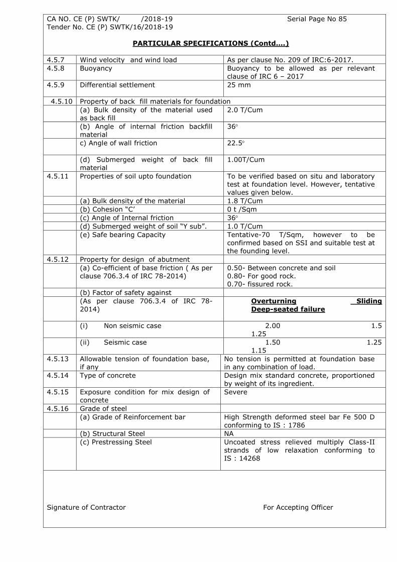
CA NO. CE (P) SWTK/ /2018-19 Serial Page No 85
Tender No. CE (P) SWTK/16/2018-19
PARTICULAR SPECIFICATIONS (Contd….)
4.5.7 Wind velocity and wind load As per clause No. 209 of IRC:6-2017.
4.5.8 Buoyancy Buoyancy to be allowed as per relevant
clause of IRC 6 – 2017
4.5.9 Differential settlement 25 mm
4.5.10 Property of back fill materials for foundation
(a) Bulk density of the material used
as back fill
2.0 T/Cum
(b) Angle of internal friction backfill
material
36
c) Angle of wall friction
22.5
(d) Submerged weight of back fill
material
1.00T/Cum
4.5.11 Properties of soil upto foundation To be verified based on situ and laboratory
test at foundation level. However, tentative
values given below.
(a) Bulk density of the material 1.8 T/Cum
(b) Cohesion “C‟ 0 t /Sqm
(c) Angle of Internal friction 36
(d) Submerged weight of soil “Y sub”. 1.0 T/Cum
(e) Safe bearing Capacity Tentative-70 T/Sqm, however to be
confirmed based on SSI and suitable test at
the founding level.
4.5.12 Property for design of abutment
(a) Co-efficient of base friction ( As per
clause 706.3.4 of IRC 78-2014)
0.50- Between concrete and soil
0.80- For good rock.
0.70- fissured rock.
(b) Factor of safety against
(As per clause 706.3.4 of IRC 78-
2014)
Overturning Sliding
Deep-seated failure
(i) Non seismic case 2.00 1.5
1.25
(ii) Seismic case 1.50 1.25
1.15
4.5.13 Allowable tension of foundation base,
if any
No tension is permitted at foundation base
in any combination of load.
4.5.14 Type of concrete Design mix standard concrete, proportioned
by weight of its ingredient.
4.5.15 Exposure condition for mix design of
concrete
Severe
4.5.16 Grade of steel
(a) Grade of Reinforcement bar High Strength deformed steel bar Fe 500 D
conforming to IS : 1786
(b) Structural Steel NA
(c) Prestressing Steel Uncoated stress relieved multiply Class-II
strands of low relaxation conforming to
IS : 14268
Signature of Contractor For Accepting Officer
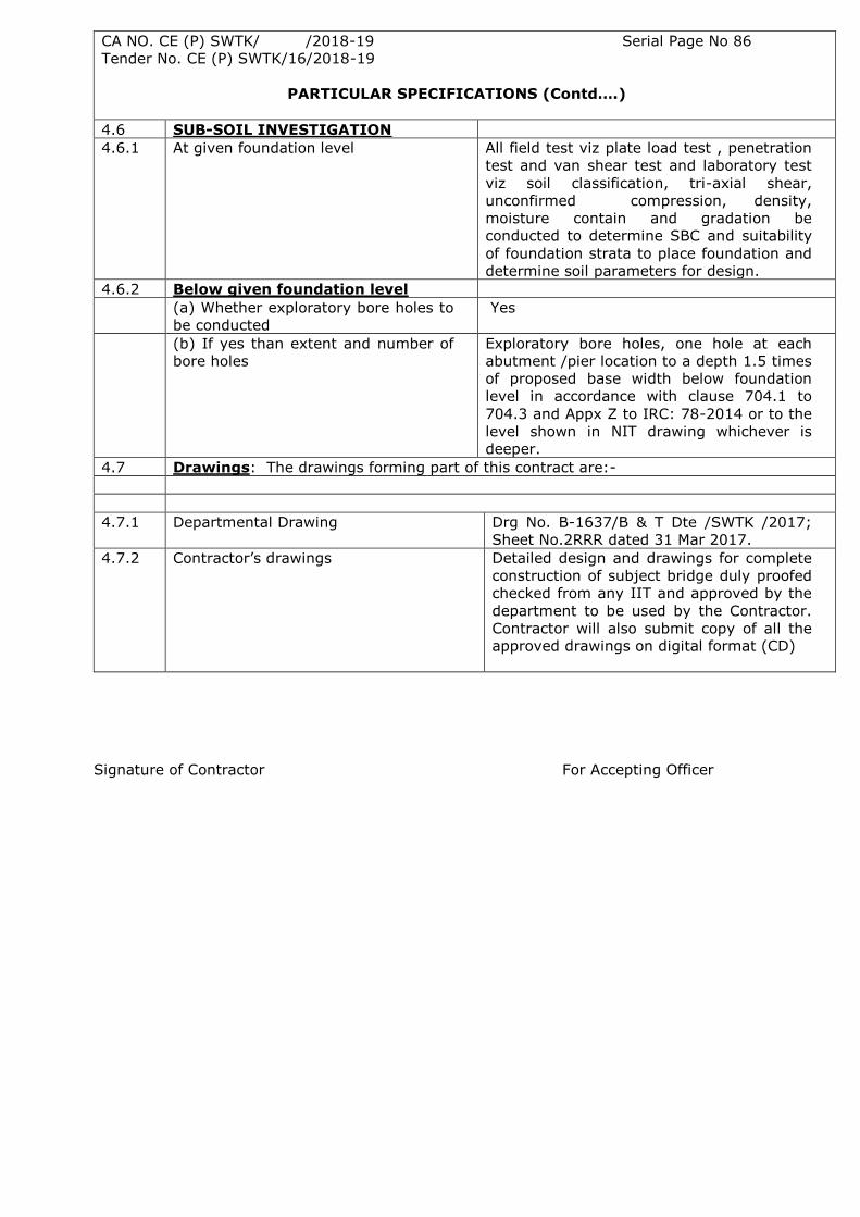
CA NO. CE (P) SWTK/ /2018-19 Serial Page No 86
Tender No. CE (P) SWTK/16/2018-19
PARTICULAR SPECIFICATIONS (Contd….)
4.6 SUB-SOIL INVESTIGATION
4.6.1 At given foundation level All field test viz plate load test , penetration
test and van shear test and laboratory test
viz soil classification, tri-axial shear,
unconfirmed compression, density,
moisture contain and gradation be
conducted to determine SBC and suitability
of foundation strata to place foundation and
determine soil parameters for design.
4.6.2 Below given foundation level
(a) Whether exploratory bore holes to
be conducted
Yes
(b) If yes than extent and number of
bore holes
Exploratory bore holes, one hole at each
abutment /pier location to a depth 1.5 times
of proposed base width below foundation
level in accordance with clause 704.1 to
704.3 and Appx Z to IRC: 78-2014 or to the
level shown in NIT drawing whichever is
deeper.
4.7 Drawings: The drawings forming part of this contract are:-
4.7.1 Departmental Drawing Drg No. B-1637/B & T Dte /SWTK /2017;
Sheet No.2RRR dated 31 Mar 2017.
4.7.2 Contractor‟s drawings Detailed design and drawings for complete
construction of subject bridge duly proofed
checked from any IIT and approved by the
department to be used by the Contractor.
Contractor will also submit copy of all the
approved drawings on digital format (CD)
Signature of Contractor For Accepting Officer
CA NO. CE (P) SWTK/ /2018-19 Serial Page No 87
Tender No. CE (P) SWTK/16/2018-19
PARTICULAR SPECIFICATIONS (Contd….)
5. IMPORTANT POINTS ON SUB-SOIL INVESTIGATION
5.1 On excavation of foundation up to the proposed foundation level, in situ test viz plate load
test, standard penetration test, vane shear test and laboratory test for classification, tri-axial shear
and un confined compression and consolidation test be conducted to assess suitability of the strata
to place foundation. In addition, where specified further investigation be carried out by taking
exploratory bores at the locations as shown in NIT Drg along the alignment of the proposed bridge
and taken up to a depth as directed by Engineer-in-charge i.e generally to a depth 1.5 times the
proposed width of foundation or the level shown in the NIT drawing (whichever is deeper).
5.2 The investigation shall be conducted to determine the suitability or otherwise of the soil or
rock to support the foundations of the bridge or other structure and also to determine soil
parameters and rock characteristics required for the design of foundations by in-situ testing or
testing of samples / cores taken from bores / drill holes. The subsurface investigation shall be
carried out in such a way that the profiles of different types of soil for the entire length of the
proposed structure are obtained and recorded. Other information to be obtained are mechanical and
physical properties such as grain-size distribution, sensitivity, existence of deleterious material in
soil or ground water, porosity of rock, subsidence due to mining, ground water lever, artesian
condition, likely sinking and driving effort and likely constructional difficulties.
5.3 Relevant Indian Standards such as IS:1498, IS:1888, IS:1892, IS:1231, IS:2132, IS:2720,
IS:4434 and IS:4968 shall be followed for guidance.
5.4 The soundings by dynamic method, where required shall be carried out in bore holes using a
standard sampler as specified in IS:2131.
5.5 In case of well foundation the well shall be sink to the given foundation level and thereafter
various in-situ and laboratory tests including exploratory boring extending to a depth 1.5 times the
proposed base width or the level shown in the NIT drawing (whichever is deeper) shall be conducted
to ascertain suitability to place foundation.
5.6 Detailed sub soil investigation and all field tests and lab tests shall be conducted in
accordance with clause 704.1 to 704.3 of IRC:78-2014 and Appendix-2 of IRC-78-2014 and Section
2400 of MoRT&H Specification on Road and Bridge work.
5.7 EXTENT AND NUMBER OF BORES
5.7.1 Investigations shall cover each foundation location of the bridge. At each foundation level,
number, location and termination level of exploratory bores holes shall be as indicated in the NIT
Drg.
5.7.2 Where detailed investigation indicates appreciable variation or where variations in a
particular foundation are likely to appreciably affect the construction (especially in case of bridge
foundations resting on rock), it will be necessary to take additional bores in the transverse direction
also, to establish complete profile of the underlying strata. The number of additional bores shall be
decided depending upon the extent of variation in local geology at a particular foundation location
and should cover the entire area of that foundation.
5.8 DEPTH OF BORES
Signature of Contractor For Accepting Officer
CA NO. CE (P) SWTK/ /2018-19 Serial Page No 88
Tender No. CE (P) SWTK/16/2018-19
PARTICULAR SPECIFICATIONS (Contd….)
5.8.1 Unless specified otherwise, each bore hole shall extend to depth 1.5 times the least
dimension of foundation below the foundation level or the level indicated in the NIT
drawing(whichever is deeper). In case during the process of excavation hard rock is encountered at
higher level than the given foundation level, the in-situ tests as appropriate and exploratory bore
holes be conducted at this level to ascertain suitability of exposed rock to place the foundation and
continuity of rock formation below that level.
5.9 DETAILED INVESTIGATION
5.9.1 The data required to be obtained from each zone will cover soil classification, particle size
distribution, shearing strength characteristics, compressibility and permeability as detailed in Table
1 of Annex 2 of IRC:78-2014. In all cases, samples of soils shall be collected at every 1m to 1.5m
depth or at change of strata.
5.9.2 Whenever a change in the subsoil strata / rock profile is encountered during construction,
further investigations shall be carried out to establish the correct data required for revised design of
foundations, if necessary.
5.9.3 The investigations shall be comprehensive enough to give the following information to the
designer:-
i) the engineering properties of the soil / rock,
ii) the location and extent of soft layers, cavities and gas pockets, if any, under the
hard founding strata,
iii) the geological condition like type of rock, faults, fissures or subsidence due to
mining, cavities, hollows, porosity etc.,
iv) ground water level,
v) artesian conditions, if any,
vi) quality of water in contact with the foundation,
vii) the depth and extent of scour,
viii) suitable depth of foundation,
ix) bearing capacity of the stratum,
x) probable settlement and differential settlement of the foundations,
xi) likely sinking or driving effort, and
xii) likely construction difficulties.
5.10 PRESENTATION OF DATA
5.10.1 The data shall be presented as per sheet No. 1 and 2, Appx-Z of IRC:78 :2014.
Signature of Contractor For Accepting Officer
CA NO. CE (P) SWTK/ /2018-19 Serial Page No 89
Tender No. CE (P) SWTK/16/2018-19
PARTICULAR SPECIFICATIONS (Contd….)
6 FOUNDATIONS
6.1 GENERAL
6.1.1 A Bridge can have open foundation, well foundation or pile foundation for its abutments
and piers. The foundation for this bridge shall be as specified in the particular specification (Site
and Design Data) and NIT drawing with due regard to the conditions peculiar to the Site and with
due consideration for existing structures and design parameters given at Clause 4 above.
6.1.2 Structure founded on rock shall be embedded into sound integral and continuous rock and
taken at least 1.50 m inside the strata as stipulated in IRC: 78- 2014. Wherever the foundation
will be resting on rock, the same is required to be anchored. The minimum anchorage
reinforcement shall be 28-mm dia HYSD steel bars at 1.0m C/C along the periphery taken at least
1.50m into the rock through minimum 65mm diameter dredge hole. Full development length of
anchoring bar (minimum 1.5 m) be anchored into concrete above the founding level. Tenderer‟s
lump sum should include such cost, if any.
6.1.3 In case concreting of foundation is done under water, at least 10% extra cement shall be
added over and above that required for the mix specified. Nothing extra shall be admissible on
this account over and above the quoted lump sum amount.
6.1.4 In case of open foundation, filling of surrounding ground will be as per IRC:78- 2014. In
case of excavation in rock the PCC filling should be limited to 0.5m above the top of footing.
6.1.5 Founding level specified will be the top of the leveling course.
6.1.6 In checking the stresses at the base of all the foundations, it shall be ensured that under
any combination specified in IRC: 78-2014, there should be no tension for any type of soil
including soil mixed with boulders, soft erodible or fissured rock. However for hard rock the
provisions of IRC: 78- 2014 shall apply.
6.1.7 The contractor shall carry out trench excavation. Open excavation to large depth is not
advisable as this disturbs the bed and bank to very large extent. Therefore, to avoid
disturbance, only trench excavation should be followed. Tenderer has to devise suitable method
to reach the foundation level either by trench excavation or by sinking the well to required level.
Lump sum quoted rates by the tenderer shall be inclusive of whatever method is adopted by him.
6.1.8 If any change in the depth of foundation becomes necessary on account of alteration in
design requirement as compared to the design requirement stipulated in the tender
documents, such variation (increase/decrease) in depth of foundation shall be adjusted through
a deviation order priced at the rates quoted in Annexure to Schedule “A”. The variation in
depth of foundation shall be reckoned with reference to the levels indicated in tender drawing.
These rates shall be deemed to include structural alterations etc, necessitated by any
variations in the design requirement and the cost of the extra efforts involved in redesigning.
6.1.9 If during construction, problems are encountered that necessitate changes in type of
foundation i.e. from open foundation to well foundation for any reason including change in soil
parameters, the same has to be done at no extra cost to the Government and department‟s
liability shall be limited only to the extent of lump sum fixed rate quoted by the contractor in
Schedule “A”. However, variation in the depth of foundation with respect to that the one shown
in the NIT drawing will be adjusted suitably through deviation order priced at the rate quoted in
Annexure „J‟ to Schedule ‟A‟.
Signature of Contractor For Accepting Officer
CA NO. CE (P) SWTK/ /2018-19 Serial Page No 90
Tender No. CE (P) SWTK/16/2018-19
PARTICULAR SPECIFICATIONS (Contd….)
6.2 OPEN FOUNDATION
6.2.1 Open foundations if adopted shall meet the requirements as specified in clause 707 of IRC
: IRC: 78-2014.
6.2.2 In case of deep excavation for open type foundations, the contractors shall use suitable
methods like sheeting and bracing etc, as approved by the OC Contract to reach the proper
foundation level without any extra cost for the method adopted by the contractor.
6.2.3 In case where the contractor on his own desires to take the foundation to a level below
those specified in the design data for taking advantage of the relief offered by the passive
resistance of soil or increased bearing capacity of the soil to meet with the design requirements of
the data specified in tender documents, nothing extra will be payable to the contractor on this
account.
6.2.4 In seismic zone, the weight of soil likely to be resting on top of the foundation shall be
taken into account while computing the seismic force.
6.2.5. Open foundations shall be designed/proportioned in such a way that ledge length of at
least 3.0 m is maintained all around.
6.3. WELL FOUNDATION
6.3.1 Foundations supporting the superstructure located in deep water channels shall
comprise of properly dimensioned wells. Where well foundation is proposed, the design and
construction of well shall conform to the stipulation given at Clause 708 of IRC-78-2014 and
Section 1200 of MoRT&H Specifications for Road & Bridge Works (Fifth revision).
6.3.2 The stability and design of well foundation shall be done under the most critical
combination of loads and forces as per Clause 706 of IRC-78-2014. The pressure on foundation
shall satisfy the provision of Clause 706 of IRC-78-2014. In case of cohesion soil the suitability
of well shall also be checked with respect to the provisions of IS-45.
6.3.3 A single circular well shall be generally adopted in design and shall have uniform
steining thickness throughout. The thickness of steining should be such that it is possible to
sink the well without excessive kentledge and without getting damaged during sinking or
during rectifying the excessive tilts and shifts. The well shall have a minimum outer diameter of
7.00 meter and steining thickness not less than 1.0 meter. Single circular well having external
diameter exceeding 12.0 m shall require special treatment as specified in Clause 708.1.2 of
IRC:78-2014.
6.3.4 Masonry wells or PCC wells are not permitted.
6.3.5 No tension is permitted at the base of well in any combination of load.
6.3.6 The cutting edge of well shall be made of structural steel and shall be strong enough to
facilitate sinking of well through the type of strata excepted to be encounter. The weight of
cutting edge shall not be less than 40 kg/per meter length.
6.3.7 In V shape cutting edge the inclined plate should meet the vertical plate in a way that
full strength connection by welding is feasible.
6.3.8 The well curb shall be in reinforced concrete having concrete mix minimum M-35 Grade
with minimum reinforcement of 72 Kg/per cum excluding bond rods.
Signature of Contractor For Accepting Officer
CA NO. CE (P) SWTK/ /2018-19 Serial Page No 91
Tender No. CE (P) SWTK/16/2018-19
PARTICULAR SPECIFICATIONS (Contd….)
6.3.9 In case blasting is anticipated for facilitating sinking through boulders and rocks, the
inner face of well curb shall be protected with steel plates of thickness not less than 10 mm
upto the top of well curb. Further, if considered necessary, the steining upto 3.0 mtr height
shall also be protected with 6 mm thick plate. In any case, this extra height of the steel plate
should not be more than 3.0 metres unless there is specific requirement. The curb as well as
3.0 mtr height of steining above the curb shall be provided with additional hoop reinforcement
of 10 mm dia bar at 150 mm spacing. Additional reinforcement above this height upto two
times the thickness of steining should be provided to avoid cracking arising out of sudden
change in effective section due to curtailment of plate.
6.3.10 The stresses in well steining shall be checked at such critical sections where tensile and
compressive stresses are likely to be maximum and also where there is change in the area of
reinforcement or in concrete mix.
6.3.11 The well steining shall be designed as a reinforced concrete column section subjected to
combined axial load and bending. The amount of vertical reinforcement provided in the steining
shall not be less than 0.20 percent of the actual gross cross sectional area of the steining. On
the inner face, a minimum of 0.06 percent (of gross area) steel shall be provided. Transverse
reinforcement in steining shall be provided in the steining shall be provided in accordance with
the provisions for a column but in no case shall be less than 0.04 percent of the volume per
unit length of the steining.
6.3.12 The stability of well shall also be checked for the construction stage where there is no
super-structure and the well is subjected to design scour, full pressure due to water current
and/or full design earth pressure.
6.3.13 As far as possible, the wells shall be sunk to plumb without any tilts and shifts. No well
shall be permitted in pre-dredged hole. The tilt of any well 1(horizontal) in 80 (vertical) and a
resultant shift of 150 mm due to translation (both additive) in a direction which will cause most
severe effect shall be considered in the design of well foundations. If the actual tilts and/or
shifts of any well exceed the above limits, then the Contractor shall have to carry out, at his
own cost, suitable remedial measures to bring the tilt and shift within permissible limits. If it is
not possible, the well so sunk shall be regarded as not conforming to specifications and
classified as a sub-standard work. The Accepting Officer, in his sole discretion, may consider
accepting such a well provided that calculations for foundation pressures, steining stresses etc,
accounting for actual tilt and shift furnished by the Contractor show that the well is safe,
remedial measures to bring the stresses within permissible values is carried out by the
Contractor at his own cost and the Contractor is subjected to reduction in rates as penalty in
accordance with Clause 1216 (g) of MoRTH Specifications (Fifth revision). In case the Accepting
Officer, in his sole discretion, rejects the well, the Contractor shall dismantle the rejected well
to the extent directed by the Accepting Officer and remove the debris. Further, the Contractor
shall at his own risk and cost, complete the bridge with modified span arrangement acceptable
to the Accepting Officer.
6.3.14 Bottom plug shall be provided in all wells and shall extend to a height of 300 mm above
well curb. Below the cutting edge, a suitable sump of 150 mm shall also be provided. The
concrete mix used in bottom plug shall have a minimum cement content of 330 Kg/m3 and a
slump of 150mm to permit easy flow of concrete through tremie to place fill-up all cavities. For
under water concreting the concrete shall be placed by termie pipe under still water and
cement content of mix be increased by 10 per cent.
6.3.15 The filling of well above bottom plug shall be done with sand, free from organic matter.
Sand filling shall commence 7 days after bottom plug. A 300 mm thick plug of M-25 concrete
shall be provided over the filling.
Signature of Contractor For Accepting Officer
CA NO. CE (P) SWTK/ /2018-19 Serial Page No 92
Tender No. CE (P) SWTK/16/2018-19
PARTICULAR SPECIFICATIONS (Contd….)
6.3.16 The bottom of well cap shall generally be laid at low as possible, but above the LWL in
active channel. Where the bed level is higher than the LWL, the bottom of well cap may be
suitably raised. Longitudinal bars coming from well steining shall be anchored into well cap.
Design of the well cap shall be based on any rational method, considering the worst
combination of loads and forces as per Clause 706 of IRC :78-2014.
6.3.17 The well shall as far as possible be sunk true and vertical through all types of strata.
Sinking or loading of the well with kentledge shall be commenced only after the steining has
been cured for at least 48 hours. For safe sinking of wells, necessary guidance may be taken
from Appendix-4 of IRC:78. Complete history of sinking of each well giving details of
concreting, sinking and problems met, if any, shall be maintained in the format given in
Appendix 1200/l of MoRTH Specifications (Fifth Revision).
6.4. PILE FOUNDATIONS
6.4.1 Piles transmit the load of a structure to competent subsoil strata by the resistance
developed from bearing at toe or skin friction along the surface or both. The construction of
pile foundation requires a careful choice of piling system depending upon subsoil conditions,
load characteristics of structures, permissible limits of total and differential settlement,
unsupported length of pile under scour and any other site specific requirement.
6.4.2 Design and construction of Pile Foundations, wherever proposed, shall be governed by
IS:2911 subject to limitations/stipulations given in Clause 709 of IRC:78-2014, Section 1100 of
MoRTH Specifications for Road and Bridges (5th revision) and these tender documents.
Appendix-5 of IRC:78-2014 gives the design formulae and their applicability. Geotechnical
capacity of piles for various factors shall be estimated in accordance with Clause 709.3 of
IRC:78.
6.4.3 The complete subsurface investigations of strata to ascertain the nature of strata
around the pile shaft and below the tip shall be carried out. Depth of boring shall not be less
than:
i) 1.5 times estimated length of pile or 15m below the proposed founding level
ii) 15 times diameter of pile in ordinary/ jointed rock but minimum 15m in such
rock.
iii) 4 times diameter of pile in hard rock but minimum 3m in such rock
6.4.4 Bored Cast-in-situ Concrete piles shall be used. Minimum diameter of concrete piles
shall be one meter for bridges. A group of two or more piles shall be adopted to support any
abutment/pier. Maximum rake to be permitted in pile shall not exceed 1 in 6. Concreting shall
be done by tremie method in accordance with Clause 709.6.2 of IRC:78.
6.4.5 The values regarding grade of concrete, minimum cement content, maximum water
cement ratio and slump shall be as under:
i) Minimum Grade of Concrete : M35
ii) Minimum Cement Content : 400 kg/m3
iii) Maximum Water Cement ratio :0.40
iv) Slump : 150 – 200 mm
Signature of Contractor For Accepting Officer
CA NO. CE (P) SWTK/ /2018-19 Serial Page No 93
Tender No. CE (P) SWTK/16/2018-19
PARTICULAR SPECIFICATIONS (Contd….)
6.4.6 A pile as a structural member shall have sufficient strength to transmit all the load
effects from structure to soil and its structural capacity examined as a column. The pile shall
also be designed to withstand the temporary stresses, if any. The permissible stresses shall be
as per IRC:112. The test pile shall be separately designed to carry test load safely to the
foundation.
6.4.7 The reinforcements in pile shall be provided complying with the requirements of
IRC:112, as per design requirements. The area of reinforcement shall not be less than 0.40 per
cent nor greater than 2.50 per cent of the actual area of cross section of piles. The clear
spacing between vertical bars shall not be less than 100 mm. Grouping of not more than two
bars together can be made for achieving the same. Lateral reinforcement shall be provided in
the form of spirals with minimum 8 mm diameter HYSD bars, spacing not more than 150 mm.
For inner layer of reinforcement, separate links tying them to each other and to outer layers
shall be provided.
6.4.8 Casting of pile cap should be at a level higher than low water level and concreting shall
be done in dry condition. Pile caps shall be of reinforced concrete. A minimum offset of 150mm
shall be provided beyond outer faces of the piles in the group. If the pile cap is in contact with
earth at the bottom, a leveling course of minimum 80mm thick plain cement concrete (M-25)
shall be provided. The top of the pile shall project 50 mm into the pile cap and reinforcements
of pile shall be fully anchored in pile cap.
6.4.9 The requirements and steps for design and installation of pile shall be as brought out
under Clause 709.2 of IRC:78-2014.Testing of Piles (Initial and Routine) shall be done as per
the procedure laid down in IS:2911, Part-IV. Important considerations, inspections and
precautions as given under Clause 709.6 of IRC:78 shall be adhered to for pile works.
6.4.10 Permissible tolerances for piles and pile caps shall be as per Clause 1116 of MoRTH
Specifications for Road and Bridge works (Fifth Revision).
6.5 ADDITIONAL DESIGN ASPECTS FOR FOUNDATIONS
6.5.1 The following design aspects shall also be taken into consideration in the design over
and above IRC Code requirement:-
a) The founding level indicated in the departmental scheme is only the minimum
level up to which the foundation will have to be taken on scour consideration or
otherwise. The tenderer shall make preliminary design calculations to arrive at the
probable founding level for his proposed scheme.
b) For open foundations, passive reliefs due to earth and wall friction are not to
be considered in the design.
c) No allowance for skin friction is permissible in the design of substructure.
Maximum horizontal forces will include the seismic forces on complete back filling
behind the abutment and resting on abutment raft or well cap or pile cap or well
steining etc.
d) The vertical component of both the active and passive pressure of soil is to be
neglected in the design.
Signature of Contractor For Accepting Officer
CA NO. CE (P) SWTK/ /2018-19 Serial Page No 94
Tender No. CE (P) SWTK/16/2018-19
PARTICULAR SPECIFICATIONS (Contd….)
e) The stability of pier wells in cohesive soil and abutment wells both in cohesive
and non-cohesive soils shall be checked in accordance with IRC: 78- 2014. The
stability of wells in non-cohesive soils shall be checked as per IRC:45.
f) The weight of water filled in well and substructure above scour will be taken into
account while calculating seismic force.
6.6 APPROVAL OF FOUNDATIONS
6.6.1 The contractor shall get the foundation strata approved by the Accepting Officer before
laying concrete for the foundations.
6.6.2 Complete details about properties of foundation strata and its safe bearing capacity
including details with regard to tilt & shift (in case of well foundation) shall be presented to
OC, Contract for obtaining approval of Accepting Officer.
7. SUBSTRUCTURE
7.1. GENERAL
7.1.1 In case of plain concrete substructure, surface reinforcement at the rate of 2.5 kg/m2
shall be provided in each direction, i.e., both horizontally and vertically. Spacing of such bars
shall not exceed 200 mm. In case of substructure in highly corrosive atmosphere (as per
Clause 14.3.1 of IRC:112-2011), the surface reinforcement can be dispensed with if specifically
allowed but the dimension of the substructure should be so proportioned to keep the stresses
only up to 90 percent of the allowable stress.
7.1.2 For the design of substructure below the level of the top of bed block, the live load
impact shall be modified by the factors given in Clause 208.7 of IRC:6-2017.
7.1.3 Structures designed to retain earth fill shall be proportioned to withstand pressure
calculated in accordance with any rational theory. No structure shall, however, be designed to
withstand to horizontal pressure less than that exerted by a fluid weighing 480 kg/m3 , in addition
to the live load surcharge if any.
7.1.4. The backfill behind the wing and return walls shall conform to the specifications in
Appendix-6 of IRC: 78-2014 with provision for proper drainage.
7.1.5. Weep holes shall be provided on all structures such as abutment, wing wall and return wall
to permit water to flow out without building up pressure in back fill. Weep holes shall be provided
with 100mm diameter PVC/HDPE pipe. The weep holes shall extend through the full width of
concrete masonry with slope of about 1 vertical to 20 horizontal towards the draining face. The
spacing of weep holes shall be one meter in either direction with lowest at 150mm above the low
water level or ground level whichever is higher or as directed by Engieer-in-Charge.
7.2 ABUTMENTS
7.2.1 The abutments will carry superstructure from one side. It should be designed
/dimensioned to retain earth from the approach embankment. Spill through type abutments shall
not be permitted.
Signature of Contractor For Accepting Officer
CA NO. CE (P) SWTK/ /2018-19 Serial Page No 95
Tender No. CE (P) SWTK/16/2018-19
PARTICULAR SPECIFICATIONS (Contd….)
7.2.2 The abutment may be plain or reinforced concrete. The abutment may be solid type or
buttressed type or counter fort type. Counter fort type abutment may be treated as T or L type as
the case may be and the slab may be designed as continuous over counter forts.
7.2.3 The abutment should be designed to withstand earth pressure in normal condition in
addition to load and forces transferred from superstructure. In addition, any load acting on the
abutment itself, including self-weight, is to be considered.
7.2.4 All abutments shall be designed for a live load surcharge of 1.20 m height of earth fill.
7.2.5 Fully earth-retaining abutments should be designed considering saturated unit weight of
earth during H.F.L. or L.W.L. condition. In case of footings, the submerged unit weight of soil
where considered shall not be less than 1000 kg/m3.
7.2.6 The weight of earth filling material on heel may be considered. In case of toe, the weight
may be considered if the bed is protected.
7.2.7 In case of abutments having counter-fort, the minimum thickness of the front wall should
not be less than 300 mm and the thickness of the counter-fort should not be less than 300 mm.
7.2.8 In case of box type abutments, weep holes shall be provided similar to hollow piers as per
Clause 710.2.9 of IRC:78-2014.
7.3 ABUTMENT PIER
7.3.1 Abutment piers may have to be provided at locations where there may be a need of
increasing waterway subsequently. The design of such abutment pier shall be such that it should
be possible to convert them to the similar shape as pier in the active channel.
7.4 DIRT WALLS, WING WALLS AND RETURN WALLS
7.4.1 Return walls shall be of sufficient length but not less than 4.0 mtr to retain the roadway to
the required extent and to provide protection against erosion. The cantilever returns where
adopted should not be more than 4 metres long.
7.4.2 A dirt wall shall be provided to prevent the earth from approaches spitting on bearings. A
screen wall extending to full depth shall be provided to prevent slipping of back fill.
7.4.3 The return walls may be of solid or counter-fort type. The material used may be plain or
reinforced concrete or masonry.
7.4.4 Dirt wall/ballast wall and screen wall shall be provided with minimum thickness of 300
mm.
7.4.5 The return walls should be designed primarily to withstand the earth pressure in addition
to self-weight.
7.4.6 The top of the return walls shall be carried above the top of embankment by at least 100
mm to prevent any soil from being blown or washed away by rain over its top. A drainage
arrangement for return wall/wing wall may be provided similar to that for the abutment specified
in IRC 78-2014.
7.4.7 In case of open foundations, wing and return wall should be provided with separate
foundations with a joint at their junction with the abutment.
Signature of Contractor For Accepting Officer
CA NO. CE (P) SWTK/ /2018-19 Serial Page No 96
Tender No. CE (P) SWTK/16/2018-19
PARTICULAR SPECIFICATIONS (Contd….)
7.4.8 The return walls may be provided at right angles to the abutment. Return walls shall be
designed to withstand a live-load surcharge equivalent to 1.2 m height of earth fill.
7.4.9 The box type return wall at right angles at both ends of the abutments connected by wall
type diaphragm may be adopted where found suitable. However, in such cases, no reduction in
the earth pressure for the design of the abutment should be considered. The top of diaphragm
should slope inwards to the centre of carriageway for facilitating proper rolling of the
embankment behind the abutment.
7.4.10 The foundation of return shall be taken adequately into the firm soil.
7.4.11 The spilling of soil at the ends of the wing wall/return wall shall be assumed to be at the
slope of 1 ½ horizontal to 1 vertical. The contractor shall be deemed to have allowed in his
design to prevent the spills from fouling the clear linear water way at HFL and bearings. Tenderer
to note that in no case the length of the cantilever type wing wall/return wall shall be more than
4.0 m, if provided, and any increase in the span of bridge on this account to suit other tender
stipulations shall not be acceptable to the department. Tenderer may provide open foundation for
wing walls/return walls and the same shall be laid at a depth not lesser than 2.5m below the
natural ground level with proper construction joints between such a wall and the abutment.
However the gravity return wall foundations shall not be made to rest on filled up soil. By
providing such return wing wall, the tenderer has to ensure the provision of effective linear
waterway and other tender clauses to the satisfaction of the department. Further the tenderer
has to ensure the soundness of such a non-load bearing structure(s) by way of suitable design as
laid down in relevant clauses of tender/relevant codes.
7.4.12 In case of cantilever return wall, bottom of the cantilever portion of the return wall
should be embedded in embankment for 500 mm and top of the return wall shall be carried up to
100 mm above the top of the slope of embankment (above 100mm) to prevent any soil from
blown/or washed by rain over its top. Back filling behind the abutment up to the original ground
level shall be carried out by the contractor as per the laid down procedure to ensure proper
compaction and reconstruction of the original SBC before excavation. Wherever, boulder or soil
filling inside the abutment has been taken into account in the design. The same shall be carried
out by the contractor up to the design level with suitable filter media as per IRC: 78 - 2014. The
back filling will be done with boulders and granular materials only. SBC at foundation level of
return wall shall be checked by plate bearing/other suitable test if necessary for safety of the
design and same shall be deemed to be within the lump sum cost.
7.5 RETAINING WALLS
7.5.1 The retaining walls shall be designed to withstand earth pressure including any live load
surcharge and other loads acting on it including self-weight in accordance with the general
principles specified for abutments. Stone, masonry and plain concrete walls shall be of solid type.
Reinforced concrete walls may be of solid, counter-fort, buttressed or cellular type. The minimum
thickness of reinforced concrete retaining wall shall be 300 mm.
7.5.2. The vertical stems of cantilever walls shall be designed as cantilevers fixed at the base.
The vertical or face walls of counter-fort type and buttressed type shall be designed as continuous
slabs supported by counter-forts or buttresses. The face wall shall be securely anchored to the
supporting counter-forts or buttresses by means of adequate reinforcements.
7.5.3. Counter-forts shall be designed as T-beams or L-beams. Buttresses shall be designed as
rectangular beams. In connection with the main tension reinforcement of counter-forts, there
shall be a system of horizontal and vertical bars or stirrups to anchor the face walls and base slab
to the counter-fort. These stirrups shall be anchored as near to the outside faces of the face walls
and as near to the bottom of the base slab as practicable.
Signature of Contractor For Accepting Officer
CA NO. CE (P) SWTK/ /2018-19 Serial Page No 97
Tender No. CE (P) SWTK/16/2018-19
PARTICULAR SPECIFICATIONS (Contd….)
7.6 PIERS
7.6.1. Piers in stream and channel should give a minimum interference to flood flow. In
general, piers should be placed parallel with the direction of stream current at flood stage.
7.6.2. Where necessary, piers shall be provided at both ends with suitably shaped cut waters
as given in IRC:6. However, cut and ease water where provided shall extend up to affluxed HFL
or higher, if necessary, from consideration of local conditions.
7.6.3. In general, Piers may be in PSC, RCC or PCC. Masonry piers are not permitted. Pier may
be solid or hollow. The multi-column piers are not permitted. The thickness of walls of hollow
concrete piers shall not be less than 500 mm.
7.6.4. Piers shall be designed to withstand the load and forces transferred from the
superstructure and the load and forces on the pier itself, apart from the effect of its self-
weight.
7.6.5. Hollow piers shall be provided with suitably located weep holes of 100 mm diameter for
enabling free flow of water to equalize the water levels on inside and outside; considering rate
of rise/fall of flood water. The pier walls should be checked to expected differential water-head
pressure and silt pressure. In absence of detailed calculations, a minimum difference of 1.50m
in water levels on two sides shall be assumed.
7.6.6. The lateral reinforcement of the walls of hollow circular RCC pier shall not be less than
0.3 percent of the sectional area of the walls of the pier. This lateral reinforcement shall be
distributed 60 percent on outer face and 40 percent on inner face.
7.7 WALL PIERS
7.7.1 When the length of solid pier is more than four times its thickness, it shall also be
checked as a wall.
7.7.2 The reinforced wall should have minimum vertical reinforcement equal to 0.3 percent of
sectional area.
7.7.3 For eccentric axial load, the wall should be designed for axial load with moment. The
moments and the horizontal forces should be distributed taking into account the dispersal by
any rational method.
7.7.4 Horizontal reinforcement should not be less than 0.25 percent of the gross area and open
links (or S-loops) with hook placed around the vertical bar should be placed at the rate of 4
links in one running metre.
7.7.5 When walls are fixed with superstructure, the design moment and axial load should be
worked out by elastic analysis of the whole structure.
7.8 PIER AND ABUTMENT CAPS
7.8.1 The width of the abutment and pier caps shall be sufficient to accommodate:-
i) The bearings leaving an offset of 150 mm beyond them.
ii) The ballast wall.
iii) The space for jacks to lift the superstructure for repair/replacement of bearings,
etc.
Signature of Contractor For Accepting Officer

CA NO. CE (P) SWTK/ /2018-19 Serial Page No 98
Tender No. CE (P) SWTK/16/2018-19
PARTICULAR SPECIFICATIONS (Contd….)
iv) The equipment for pre-stressing operations where necessary.
v) The drainage arrangement for the water on the cap.
7.8.2 The thickness of cap over the hollow pier or column type of abutment should not be less
than 250 mm but in case of solid plain or reinforced concrete pier and abutment, the thickness
can be reduced to 200 mm.
7.8.3 Pier/abutment caps should be suitably designed and reinforced to take care of
concentrated point loads dispersing in pier/abutment. Caps cantilevering out from the supports
or resting on two or more columns shall be designed to cater for the lifting of superstructure on
jacks for repair/replacement of bearings. The locations of jacks shall be predetermined and
permanently marked on the caps.
7.8.4 In case bearings are placed centrally over the columns and the width of bearings/pedestals
is located within half the depth of cap from any external face of the columns, the load from
bearings will be considered to have been directly transferred to columns and the cap beam need
not be designed for flexure.
7.8.5 Except the portion under bearings, the top surface of caps should have suitable slope in
order to allow drainage of water.
7.9 CANTILEVER PIER AND ABUTMENT CAP
7.9.1 When the distance between the load/centre line of bearing from the face of the support is
equal to or less than the depth of the cap (measured at the support) the cap shall be designed as
a corbel.
7.9.2 The equivalent square area may be worked out for circular pier to determine the force of
support for calculating bending moments.
7.9.3 In case of wall pier and the pier cap cantilevering out all around the measurement of
distance for purpose of the design as bracket and the direction of provision of reinforcement
should be parallel to the line joining the centre of load/bearing with the nearest supporting space
of pier.
7.9.4 Where a part of the bearing lies directly over the pier, calculation of such reinforcement
should be restricted only for the portion which is outside the face of the pier. Moreover in such
cases the area of closed horizontal stirrups may be limited to 25 per cent of the area of primary
reinforcement.
7.10 PEDESTALS BELOW BEARINGS
7.10.1 The pedestals should be so proportioned that a clear offset of 150mm beyond the edges
of bearings is available.
7.10.2 The height of pedestal should be between 150mm and 500mm. Where the depths of
substructure from two adjacent spans on a common pier differ and require use of pedestals of
more height below one of the spans, the shape of pier cap or the diaphragm of superstructure
shall be modified to restrict the height of pedestals to 500mm.
Signature of Contractor For Accepting Officer
CA NO. CE (P) SWTK/ /2018-19 Serial Page No 99
Tender No. CE (P) SWTK/16/2018-19
PARTICULAR SPECIFICATIONS (Contd….)
7.10.3. The allowable bearing pressure on the loaded area shall be calculated as per
Clause 710.10.3 of IRC:78-2014.
7.10.4 The two layers of mesh reinforcement- one at 20mm from top and the other at 100mm
from top of pedestal or pier cap each consisting of 8mm bars at 100mm in both directions,
shall be provided directly under bearings.
8 BEARINGS AND EXPANSION JOINTS
8.1 BEARINGS
8.1.1 Large capacity bearings such as POT, POT-cum PTFE bearings shall be provided unless
specified otherwise in Schedule „A‟. Pot bearings shall consist of a metal piston supported by a
disc of unreinforced elastomer confined within a metal cylinder to take care of rotation. Horizontal
movement, if required, shall be provided by sliding surfaces of PTFE pads sliding against stainless
steel mating surfaces, with system of sealing rings. Pot bearings shall consist of cast steel
assemblies.
8.1.2. The materials, design and manufacturing of bearings shall comply with various provisions
of IRC:83-Part.III. The components of POT/PTFE bearings shall be designed/manufactured
conforming to Clause 2006 of MoRTH‟s Specifications for Road and Bridge works, (Fifth revision)
and IRC-83 (Part-III)- 2002. The properties of elastomer to be used for the components of
bearings shall comply with provisions of Table 2000-1 of MoRTH Specifications (Fifth Revision).
The confined elastomer inside the POT shall have properties as given in Table 1 of IRC:83 (Part-
II)-2015 and Table 2000-4 of MoRTH Specifications for Road and Bridge works (Fifth revision).
8.1.3. Fitting and fixing in position of bearings shall be carried out in a workman like manner
according to the instructions and to the satisfaction of the OC contract.
8.1.4. Load testing of the bearings shall be carried out by the Contractor for a load of 1.25 times
of design load at no extra cost to the Government and a certificate produced for perusal/record of
the OC Contract.
8.1.5. In order to ensure proper distribution of heavy loads, portions of girders and abutments in
contact with the bearings shall be suitably reinforced with mild steel reinforcement.
8.1.6. The contractor must ensure sufficient working space around the bearings and submit a plan
for jacking up the superstructure for the purpose of replacement of bearings.
8.1.7. The bearings shall be designed to resist both horizontal and vertical seismic effects as
specified in the code of practice.
8.1.8. Suitable easy access to the bearings shall be provided for inspection and maintenance.
Provision shall be made for jacking up the superstructure so as to allow repair/replacement of the
bearings.
8.1.9 CERTIFICATION AND MARKING
(a) Bearing should be transported to bridge site after final acceptance by inspection
authority appointed by OC Contract/Accepting Officer along with an authenticated copy of
the certificate of acceptance. An information card listing the required bearing
characteristics, duly certified by the manufacturer should also be appended with the
certificate.
Signature of Contractor For Accepting Officer
CA NO. CE (P) SWTK/ /2018-19 Serial Page No 100
Tender No. CE (P) SWTK/16/2018-19
PARTICULAR SPECIFICATIONS (Contd….)
(b) All bearings shall have suitable index markings in indelible ink or flexible paint,
which if practicable, shall be visible even after installation, giving the following
information:-
i) Name of manufacturer
ii) Month and year of manufacture
iii) Bearing designation
iv) Type of bearing
v) Load and movement capacity
vi) Centre line markings to facilitate installation
vii) Direction of major and minor movement, if any
viii) Preset, if any
8.2 EXPANSION JOINTS
8.2.1 The expansion joints shall be “Strip Seal expansion Joint” conforming to Section 2600 of
MoRTH Specifications for Road and Bridge works (Fifth revision). Its components and their salient
specifications are as under:-
8.2.2 Edge Beam : This shall be either extruded or hot rolled steel section or cold rolled
cellular steel section with suitable profile to mechanically lock the sealing elements in place
throughout the normal movement cycle. Further, the configuration shall be such that the section
has a minimum thickness of 10 mm all along its cross section (Flange & Web). Thickness of
lips holding the seal shall not be less than 6 mm. The minimum height of the edge beam
shall be 150mm.
8.2.3 Anchorages : Edge beams shall be anchored to the deck by reinforcing bars, or anchor
plates cast in concrete or a combination of anchor plate and reinforcing bars, Anchor bars, shall
engage the main structural reinforcement of the deck and in case of anchor plates or loops, this
shall be achieved by passing transverse bars through the loops or plates. The minimum thickness
of anchor plate shall be less than 0.70 times the diameter of anchor loop or 12mm, whichever is
higher. Total cross sectional area of bar on each side of the joint shall not be less than 1600mm2
per meter length of the joint and the center to center spacing shall not exceed 250mm. The
ultimate resistance of each anchorage shall not be less than 600 KN/m in any direction.
8.2.4 Material
(a) The steel for edge beams shall conform to any of the steel grade corresponding to
RST 37-2 OR 37-3(DIN), ASTM A36 or A588, CAN/CSA Standard G40.21 Grade 300W and
Quality BO of IS:2062. For subzero condition, material for steel shall conform to Quality C
of IS:2062.
(b) Anchorage steel shall conform to Quality B0 of IS: 2062-2011 and subzero
condition, Quality C of IS:2062 or equivalent.
(c) All steel sections shall be protected against corrosion by hot dip galvanizing or any
other approved anticorrosive coating with a minimum thickness of 100 micron.
Signature of Contractor For Accepting Officer
CA NO. CE (P) SWTK/ /2018-19 Serial Page No 101
Tender No. CE (P) SWTK/16/2018-19
PARTICULAR SPECIFICATIONS (Contd….)
(d) The sealing element shall be made of Chloroprene Rubber (CR). The properties
of chloroprene rubber shall be as specified in Table 2600-1 “Properties of Chloroprene
Seal”, MoRTH Specifications for Road and Bridge Works (Fifth Revision).
8.2.5 Fabrication (Pre-installation)
(a) The strip seal joint system and all its component parts including anchorages shall
be supplied by the manufacture system supplier.
(b) The width of the gap to cater for movement due to thermal effect, pre-stress,
shrinkage and creep, superstructure deformations (if any) and sub-structure deformations
(if any) shall be determined and intimated to the manufacturer. Depending upon the
temperature at which the joint is to be installed, the gap dimension shall be preset.
c) Each strip seal expansion joint system shall be fabricated as a single entity unless
stage construction or excessive length prohibits monolithic fabrication. It shall fit the full
width of the structure as indicated on the approved drawing. The system shall be preset
by the manufacturer prior to transportation. Presetting shall be done in accordance with
the joint opening indicated on the drawing.
d) The manufacturer prior to transportation. Presetting shall be done in accordance
with the joint opening indicated on the drawing.
e) The finally assembled joint shall then be clamped and transported to the work site.
8.2.6 Handling and storage.
(a) For transportation and storage, auxiliary brackets shall be provided to hold the joint
assembly together.
(b) The manufacturer/supplier shall supply either directly to the Engineer or to the
Bridge Contractor all the materials of strip seal joints including sealant and all other
accessories for the effective installation of the joints.
(c) Expansion joint material shall be handled with care. It shall be stored under cover
on suitable wooden padding to prevent damage.
8.2.7 Installation
8.2.7.1 Taking the width of gap for movement of the joint into account, the dimensions of
the recess in the decking shall be established in accordance with the drawings or design data of
the manufacturer. The surfaces of the recess shall be thoroughly cleaned and all dirt and debris
removed. The exposed reinforcement shall be suitably adjusted to permit unobstructed lowering
of the joint into the recess.
8.2.7.2 The recess shall be shuttered in such a way that dimensions in the joint drawing are
maintained. The formwork shall be rigid and firm.
8.2.7.3 Immediately prior to placing the joint, the presetting shall be inspected. Should the
actual temperature of the structure be different from the temperature provided for presenting
correction of the presetting shall be done. After adjustment, the brackets shall be tightened
again.
Signature of Contractor For Accepting Officer
CA NO. CE (P) SWTK/ /2018-19 Serial Page No 102
Tender No. CE (P) SWTK/16/2018-19
PARTICULAR SPECIFICATIONS (Contd….)
8.2.7.4 The joint shall be lowered in a pre-determined position. Following placement of
the joint in the prepared recess, the joint shall be leveled and finally aligned and the anchorage
steel on one side of the joint welded to the exposed reinforcement bars of the structure upon
completion, the same procedure shall be followed for the other side of the joint. With the
expansion joint finally held at both sides, the auxiliary brackets shall be released, allowing the
joint to take up the movement of the structure.
8.2.7.5 High quality concrete shall then be filled into the recess. The packing concrete must
feature low shrinkage and have the same strength as that of the superstructure, but in any case
not less than M-35 grade. Good compaction and careful curing of concrete is particularly
important. After the concrete has cured, the movable installation brackets and shuttering still in
place shall be removed.
8.2.7.6 Rolled up neoprene strip seal shall be cut into the required length and inserted between
the edge beams by using a crow bar pushing the bulb of the seal into the steel grooves of the
edge beams. A landing to a bead shall be formed in the thickened end of the edges of the seal
which would force the thickened end against the steel beam due to wedge effect when the strip
seal is buttoned in place.
8.2.7.7 As soon as the concrete in the recess has become initially set, a sturdy ramp shall be
placed over the joint to protect the exposed steel beams and neoprene seals from the site traffic.
Expansion joint shall not be exposed to traffic before the carriageway surfacing is placed.
8.2.7.8. The carriage way surfacing shall be finished flush with the top of the steel sections. The
actual junction of the surfacing/wearing coat with the steel edge section shall be formed by a
wedge shaped joint with a sealing compound. The horizontal leg of the edge beam shall be
cleaned beforehand. It is particularly important to ensure through and careful compaction of the
surfacing in order to prevent any premature depression forming in it.
8.2.8. Acceptance Criteria
i) All steel elements shall be finished with corrosion protection system.
(ii) For materials the acceptance test shall conform to the requirements in at Para 8.2.4
above. The manufacturer/ supplier shall produce a test certificate accordingly, conducted
in a recognized independent laboratory, in India or abroad.
(iii) The manufacturer shall produce test certificates indicating that anchorage system
had been tested in a recognized laboratory to determine optimum configuration of
anchorage assembly under dynamic loading.
(iv) Prior to acceptance 25 percent of the completed and installed joints, subject to a
minimum of one joint, shall be subjected to water tightness test. Water shall be
continuously ponded along the entire length for a minimum period of 4 hours for a depth
of 25mm above the highest point of deck. The width of ponding shall be at least 50mm
beyond the anchorage block of the joint on either side. The depth of water shall not fall
below 25mm anytime during the test. A close inspection of the underside of the joint shall
not reveal any leakage.
(v) Investigation of fatigue strength of the edge beam section with anchorages to
withstand 2x10 load change cycles of 85 KN vertical load and 10 KN of horizontal load
without showing sign of distress shall be required. The supplier shall produce a test
certificate in this regard conducted in a recognized laboratory, in India or abroad.
Signature of Contractor For Accepting Officer
CA NO. CE (P) SWTK/ /2018-19 Serial Page No 103
Tender No. CE (P) SWTK/16/2018-19
PARTICULAR SPECIFICATIONS (Contd….)
(vi) As strip seal type of joints is specialized in nature, generally of the proprietary type,
the manufacturer shall be required to produce evidence of satisfactory performance of this
type of joint.
9. SUPERSTRUCTURE
9.1. GENERAL
9.1.1. The type of bridge superstructure shall be as specified under Schedule “A” and Site and
Design Data of these specifications and design shall conform to relevant IRC & BIS Codes, MoRTH
Specifications, requirements of these specifications and sound engineering practice. All design
data including climatic data, temperature differential etc will be accounted for in the design of
superstructure. The superstructure shall be resting on bearings as specified in these documents
and designed as per relevant IRC Codes.
9.1.2. Common type of bridge superstructures are steel truss superstructure (through type/deck
type)/steel girder with RCC deck slab, post tensioned pre-stressed concrete (box girder/I-girder
system and composite RCC deck slab) and arch type (steel/PSC).
9.1.3. The following type of construction shall not be acceptable:-
a) Series of arch span.
b) The superstructure of such a design which may lead to collapse of series of
span due to failure of one of the piers or span.
c) An unbalanced cantilever type of superstructure which involves the use of
one hinge or articulation in each span.
d) Hinge arrangement in balanced cantilever type of bridge.
9.1.4. Department prefers the span arrangements as given in Site and Design Data‟ of these
specifications. Any change in length of the bridge or deck level due to site conditions shall be
considered as deviation and shall be priced as per the formulae provided elsewhere in the tender
documents.
9.2 STEEL SUPERSTRUCTURE
9.2.1 GENERAL
9.2.1.1. The design of steel superstructure shall conform to IRC:24-2010. IRC:22-
2015 shall be referred in case of concrete work composite with steel. Limit State Method
of design shall be followed. The steel superstructure shall have steel trusses with RCC
deck slab having thickness not less than 200 mm.
9.2.1.2. For all members of the steel superstructure, the minimum thicknesses of
plates and rolled sections shall conform to Clause 504.7 of IRC:24-2010. The depth of the
bottom chords and bracing shall be suitably adjusted to allow access for proper inspection
of bearings and to facilitate construction. Splices in chord members shall not be permitted.
9.2.2. CROSS BEAMS/CROSS GIRDERS
(a) For the loaded chords, the corresponding panel points of the two trusses shall be
joined by cross beams, also called as Cross Girders. Also, the corresponding panel points
of unloaded chords of the two trusses shall be connected by suitably designed members to
act as horizontal bracing.
Signature of Contractor For Accepting Officer
CA NO. CE (P) SWTK/ /2018-19 Serial Page No 104
Tender No. CE (P) SWTK/16/2018-19
PARTICULAR SPECIFICATIONS (Contd….)
(b) These cross beam will support stringers running parallel to the length of the truss.
Preferably, the RCC deck slab will be supported by stringers. If stringers are not provided,
RCC deck slab may be supported directly by cross beams.
(c ) Cross beams and/stringers shall be designed as composite structure in accordance
with IRC:22-2015. Properly designed shear connectors shall be provided on cross-
beams/stringers. Spacing of shear connectors shall not exceed 250mm c/c.
(d) If chord members are fabricated using built up sections, the loaded chord members
shall be adequately strengthened at the locations where cross girders are connected to
the chords for proper transfer of loads from cross girder to the chord member without
local overstressing of the connected chord section. Similar precaution shall be taken with
cross girders while connecting stringers with cross girders.
9.2.3 MINIMUM DEPTH : Minimum effective depth of trusses preferably shall not be less than
“1/10” of the effective span.
9.2.4. SPACING OF TRUSSES AND GIRDERS : The distance between the centre of trusses and
finders shall be sufficient to prevent over turning or over stressing due to lateral forces. This
distance shall not be less than “1/20” of the span.
9.2.5. JOINTS AND STRINGERS : The stringers shall be of steel. They shall be securely
fastened to cross beams except where arrangement is made to permit expansion. Suitable
arrangements for supporting such stringer shall be designed. Stringers should have free ends
below the expansion joints in decking.
9.2.6. BRACINGS : In all spans bracing shall be provided to transmit to the abutments the
effect of the lateral and longitudinal forces, wherever the overhead clearance permits. Lateral
diagonal bracings should preferably be provided in the planes of both upper and lower chords of
through spans. The floor system may be taken as part of the bracing system provided if it is
designed for that purpose. Wherever the depth of the girder allows, intermediate sway bracing
may be provided. Sway bracing when provided shall be proportioned to transmit to the chord
supported on bearings through the web members at least 50% of the panel lateral load and the
vertical members shall be designed to resist the resulting bending moment. Through truss spans
shall be provided with portal bearings as deep as the clearance will allow. Also, diagonal bracings
joining top chords of the two trusses at joints in horizontal plane shall be provided. In Deck type
spans, in addition to the lateral diagonal bracings provided in the planes of upper and lower
chords, diagonal bracings in form x-frames joining top and bottom chords at diagonally opposite
panel points shall be provided in vertical plane at all panel points.
9.2.7. END CROSS GIRDER : End cross girders or cross frames shall be provided in all square
ended truss and girder spans and as far as possible in skew spans. These shall preferably be
designed to permit use of jacks for lifting the superstructure. Cross girders and cross frames shall
also be provided at all intermediate points along the length of girder.
9.2.8. RIVETS, RIVET BARS AND HSFG BOLTS : All rivets and rivet bars shall conform in all
respects to IS: 1148/1149 Specifications for rivet bars for structural purposes. The riveting shall
be done by hydraulic or pneumatic machine. High Strength Friction Grip (HSFG) bolts shall
conform to IS:3757 and IS:4000, with appropriate nuts and washers. Connections made with
rivets and HSFG bolts shall conform to Clause 512.5 and Clause 512.6 of IRC:24-2010. A HSFG
bolt completely tightened shall not be reused under any circumstances. Bearing type bolted
connections shall not be permitted.
Signature of Contractor For Accepting Officer
CA NO. CE (P) SWTK/ /2018-19 Serial Page No 105
Tender No. CE (P) SWTK/16/2018-19
PARTICULAR SPECIFICATIONS (Contd….)
9.2.9. WELDING : Mild steel electrodes shall comply with the requirements of the IS:814
Specification for covered electrodes for metal arc welding of mild steel and procedure shall
comply with provisions of IS:816, IS:1024 and IS:9595, as appropriate. The welding be
carried out as specified in Clause 512.4 of IRC: 24- 2010.
9.2.10. SOLID WEB GIRDERS : Solid web girders shall be proportioned on the basis of
the amount of inertia of the cross section with the vertical axis at the centroid of the section. In
computing the maximum stress, the stress calculated on this basis shall be increased in the ratio
of gross to effective area of the flange section. The slenderness ratio of a girder shall not exceed
300. The flanges of the plate girder shall be connected to the web by sufficient rivets, bolts or
welded to transmit the horizontal shear force combined with any vertical loads which are directly
applied to the flange. The thickness of the web plates shall not be less than 8mm.
9.2.11. ASSEMBLING STEEL : The part shall be accurately assembled as shown on the
bearings and match marks shall be followed. The material shall be carefully handled so that no
parts will be bent, broken or otherwise damaged. However, any error in the shop fabrication or
deformation, resulting from handling and transportation which prevents proper assembling and
fitting up to of parts by moderate use of drifts or by a moderate amount of reaming and slight
chipping or cutting shall be reported immediately to Engineer-in Charge and his approval of the
method of erection obtained.
9.2.12. GUSSET PLATES: Gusset plates shall be so shaped and connectors so arranged
as to avoid stress concentrations. The gusset plates must not be less than 9 mm thick and should
be of ample thickness to resist shear, direct stresses and flexural action on the weakest or
critical section of maximum stress. Re-entrant cuts shall be avoided as far as possible.
9.2.13. SPLICES: As for as possible, splices shall be avoided in the members. Splices shall
not be permitted in any chord members for any reasons whatsoever.
9.2.14. DURABILITY REQUIREMENTS
a) The design, fabrication and erection details of exposed structures should be such
that good drainage of water is ensured. Standing pool of water, moisture accumulation and
rundown of water for extended duration are to be avoided.
b) The details of connections should ensure that:
i) All exposed surfaces are easily accessible for inspection and
maintenance.
ii) All surfaces not so easily accessible are completely sealed against
ingress of water.
c) Steel surfaces shall be provided at least one coat of primer of immediately after
its surface preparations, such as sand blasting to remove of mill scale and rust to
expose steel.
d) Steel without protective coating shall not be stored for long duration in
outdoor environment.
e) Surfaces to transfer forces by friction as in HSFG connections shall not be painted.
However, it shall be ensured that moisture is not trapped on such surfaces after
pretensioning of bolts by proper protective measures.
Signature of Contractor For Accepting Officer
CA NO. CE (P) SWTK/ /2018-19 Serial Page No 106
Tender No. CE (P) SWTK/16/2018-19
PARTICULAR SPECIFICATIONS (Contd….)
f) Members to be assembled by welding shall not be prepainted at the adjacent to the
location of such welds. However, after welding appropriate protective coatings shall be
applied in the region. If the contact surfaces cannot be properly protected against ingress
of moisture by surface coating, they should be completely sealed by appropriate welds.
g) Prepainted members shall be protected against abrasion of the coating during
transportation, handling and erection.
9.2.15. EXTRA SAFETY MARGIN TO LOW TEMPERATURE : The permissible stresses
shall be reduced by 15% for secondary stress due to low temperature. Also, structural steel
conforming to Quality “C” of IS:2062 shall be used for subzero conditions.
9.3 PSC /RCC SUPERSTRUCTURE
9.3.1. GENERAL
9.3.1.1. In case of T-Beams or I-Beams, the thickness of the web shall not be less
than 200mm plus diameter of duct hole and the minimum thickness of deck slab
including that at cantilever tips shall be 200mm. The number of longitudinal
beams/girders shall not be less than three.
9.3.1.2. In case of PSC Box Girders, the thickness of the web shall not be less than
“d/36 plus twice the clear cover to the reinforcement plus diameter of the duct hole” (
where “d” is the overall depth of the box girder measured from the top of the deck slab
to the bottom of the soffit) or “200mm plus diameter of duct holes”, whichever is
greater. Where cables cross within the web, suitable increase in the thickness over and
above shall be made. In case of cast in situ cantilever construction, , if the pre-stressing
cables are anchored in the web, uniform thickness of the web shall not be less than 350
mm nor less than that recommended by the pre-stressing system manufacturer, subject
to design requirements.
9.3.1.3. The thickness of the bottom flange of box girder shall be not less than 1/20th
of the clear web spacing at the junction or 200mm whichever is more. The minimum top
flange thickness shall not be less than 200mm. For top and bottom flange having
prestressing cables, the thickness of such flange shall not be less than 200mm plus
diameter of duct hole.
9.3.1.4. In case of segmental construction for bridges located in marine environment
continuity of un-tensioned reinforcement from one segment to the next must be
ensured, by providing full lap length as necessary.
9.3.1.5. For cantilever construction, preference shall be given to box type cross section
with diaphragms provided at supports. Sudden change in depth of superstructure shall
not be permitted. For reducing the thermal effect suitable ventilation may be provided
for hollow box sections.
9.3.1.6. In case of multi-beam arrangement, the number of diaphragms shall not be
less than three. For bridges having beam and slab type of superstructure, the number
of longitudinal girders shall not be less than three. The depth of the end cross
diaphragms shall be suitably adjusted to allow access for proper inspection of bearings
and to facilitate positioning of jacks for further lifting up of the superstructure.
Signature of Contractor For Accepting Officer
CA NO. CE (P) SWTK/ /2018-19 Serial Page No 107
Tender No. CE (P) SWTK/16/2018-19
PARTICULAR SPECIFICATIONS (Contd….)
9.3.1.7. Haunches of minimum size 300 mm (horizontal) and 150mm (vertical) shall
be provided at the four extreme inner corners of box section. For all other corners,
fillets of suitable size may be provided.
9.3.1.8. The minimum clear height inside the box girders shall be 1.5m to facilitate
inspections.
9.3.1.9. The depth of the suspended span at the articulation should be equal to the
depth available at the cantilever tip. Drop in spans with halved joints (articulations)
shall not be provided as far as practicable
9.3.1.10. Cross girders or diaphragms in box girders shall be provided as under:
(a) Cross girders monolithic with the deck slab shall be provided at bearings
and also at the ends of cantilever. Intermediate cross girders/diaphragms shall
be provided depending upon design requirements.
(b) Diaphragm spacing for curved girders shall be given special consideration.
(c) Thickness of diaphragms shall not be less than the minimum web
thickness.
9.3.1.11. The cross beam of a superstructure at abutment position should be
suitably designed to withstand the superstructure load, necessitated due to jacking up
of the superstructure. A drawing showing the arrangement for jacking up the
superstructure shall also be submitted along with the design. The abutment cap should
be wide enough to facilitate jacking operation.
9.3.1.12. Only stress relieved low relaxation strands (Class-2) conforming to
IS:14268 shall be used. In absence of actual testing, the design value of relaxation for
long term losses shall be taken as three times the 1000 hours value measured at initial
stress of 70 per cent UTS. For initial stress other than 70 percent of UTS, the values
given in Table 6.2 of IRC:112-2011 may be used. The thousand hour relaxation loss
value shall be obtained from the manufacturer of pre-stressing steel. This data shall be
independently cross checked to ascertain its veracity. The 1000 hour relaxation value
shall not be more than 2.5 percent of 0.70 UTS, tested at 0.7 UTS and 20 degree
Celsius. For periods less than 1000 hours, the value of relaxation loss may be taken as
per Table 6.3 of IRC:112-2011.
9.3.1.13. Limit State Method of Design as per IRC:112 shall be followed. In case of
segmental construction of superstructure, the ultimate shear capacity and flexure
capacity of section shall be multiplied by factors of 0.90 and 0.95 respectively and then
considered in the design accordingly.
9.3.1.14. The maximum permissible jacking force (inclusive of any over stressing shall
not exceed 70 percent of the minimum ultimate tensile strength (UTS) of the pre-
stressing steel. The maximum force shall be adopted as per IRC 112-2011.
9.3.1.15. The limit state of serviceability of the structure shall also be checked for
10% higher and 10 % lower pre-stressing forces and the same shall satisfy the codal
requirements as per Clause No. 7.9.5 of IRC 112-2011.
9.3.1.16. Minimum diameter of un-tensioned reinforcement should be 10 mm.
Signature of Contractor For Accepting Officer
CA NO. CE (P) SWTK/ /2018-19 Serial Page No 108
Tender No. CE (P) SWTK/16/2018-19
PARTICULAR SPECIFICATIONS (Contd….)
9.3.2. POST TENSIONED STRESSING
9.3.2.1. Tensioning force shall be applied in gradual and steady steps, in such a
manner that the applied tensions and elongations can be measured at all times. The
sequence of stressing, applied tensions and elongations shall be in accordance with the
approved drawing. It shall be ensured that in no case, the load is applied to the
concrete before it attains the strength specified on the approved drawing or as
stipulated by the pre-stressing system supplier, whichever is more. After pre-stressing
steel has anchored, the force exerted by the tensioning equipment shall be decreased
gradually and steadily so as to avoid shock to the pre-stressing steel or anchorage.
9.3.2.2. The tensioning force applied to any tendon shall be determined by direct
reading of the pressure gauges or dynamo-meters and by comparison of the measured
elongation with calculated elongation. The calculated elongation shall be invariably
adjusted with respect to the modulus of elasticity of steel for the particular lot as given
by the manufacturer.
9.3.2.3. The difference between calculated and observed tension and elongation during
pre-stressing operation shall be regulated as under:
a) If calculated elongation is reached before the specified gauge pressure, continue
tensioning till the specified gauge pressure is attained, provided the elongation does
not exceed 1.05 times the calculated elongation. If 1.05 times the calculated
elongation is reached before the specified gauge pressure is attained, stop stressing
and inform the Designer & B & T Dte, HQ DGBR.
b) If calculated elongation has not been reached at the specified gauge pressure,
continue tensioning by intervals of 5 kg/sq. cm until the calculated elongation is
reached, provided the gauge pressure does not exceed 1.05 times the specified
gauge pressure.
c) If the elongation at 1.05 times the specified gauge pressure is less than 0.95
times the calculated elongation, the following measures must be taken, in
succession, to determine the cause of discrepancy:
i) Check the correct functioning of the jack, pump and leads.
ii) De-tension the cable. Slide it in its duct to check that it is not blocked by
mortar which has entered through the holes in the sheath. Re-tension the
cable, if free.
iii) Re-establish the modulus of elasticity of steel for the particular lot from
an approved laboratory. If the required elongation is still not obtained,
further finishing operations such as cutting or sealing should not be
undertaken without approval of Designer and B & T Dte, HQ DGBR.
d) When stressing from one end only, the slip at the end remote from the jack,
shall be accurately measured and appropriate allowance made in the measured
extension at the jacking end.
9.3.2.4. A complete record of pre-stressing operations along with elongation and
jack pressure shall be maintained in the format given in Appendix 1800/ll of MoRTH
Specifications for Road and Bridge Works (Fifth Revision).
Signature of Contractor For Accepting Officer
CA NO. CE (P) SWTK/ /2018-19 Serial Page No 109
Tender No. CE (P) SWTK/16/2018-19
PARTICULAR SPECIFICATIONS (Contd….)
9.3.2.5. The positioning of pre-stressed cables shall be such as to facilitate easy
placement and vibration of concrete in between the tendons. Use of high capacity
tendons shall be preferred to avoid grouping/clustering of cables and to reduce the
number of cables. However, while two or more rows of cables have to be used, the
cables shall be vertically in line with adequate space to enable easy flow of concrete.
9.3.2.6. The number of stages of pre-stressing and grouting shall be reduced to the
minimum, preferably not more than 2. Wherever 2 stage pre-stressing is contemplated,
at the location of the 2nd stage cables in the sheathing already provided, a preformed
dummy core shall be provided and pulled out after the first stage pre-stressing and
grouting is over. Thereafter, the cables for the 2nd stage shall be threaded into
performed duct by a threading machine or any contrivance. In such situation, it shall be
ensured that cable or group of cables proposed to be grouted later are located at a clear
distance not less than 100 mm from the cables or group of cables being grouted earlier.
However, in segmental construction, where it may be necessary to adopt multi-stage
pre-stressing, the clear spacing between the first and subsequent group of cables shall
be minimum of 150 mm. Anchoring of cables in the top deck surface shall be avoided.
All anchorages shall be properly sealed after pre-stressing and grouting operations are
over. All wires/strands in one cable should be stressed simultaneously by using multi
stressing jack. Pre-stressing steel shall be continuously protected against corrosion,
until grouted.
9.3.2.7. Grouting of pre-stressed tendons shall be carried out immediately of stressing
in accordance with provisions in Appendix 1800/lll and a record of grouting operations
shall be maintained in the format given in Appendix 1800/lV of MoRTH Specifications.
The following additional specifications for grouting shall be ensured over and above
those contained in IRC:112-2011 & MoRTH Specifications:-
(a) Mixing of grout must be done in colloidal mixer such that the grout mix is
maintained in a homogenous colloidal state during the entire grouting process.
(b) The temperature of the grout after accounting for the ambient
temperature of the structure shall not exceed 30ºC.
9.3.2.8. Pre-stressing operation and grouting shall be entrusted only to specially
trained and qualified personnel.
9.3.3. PRESTRESSING STEEL, SYSTEM AND ACCESSORIES
9.3.3.1. The pre-stressing steel shall be uncoated stress relived low relaxation seven ply
Class-2 strands conforming to IS:14268 and procured from reputed manufacturers. The
manufacturer shall supply high tensile strands in coils of sufficiently large diameters,
such as tendons shall retain their physical properties and shall be straight as they
unwind from the coil. Tendons of any type that are damaged, kinked or bent shall not
be used. The packing of pre-stressing strand shall be removed only just prior to forming
of cables for placement.
9.3.3.2. All tensioning equipments and pre-stressing accessories shall be procured from
authorized manufacturers with in house testing facilities. The stressing equipment, de-
stressing/re-stressing facilities, and grouting arrangements shall be compatible with
tendons.
9.3.3.3. Sheathing pipes, Anchorages and other accessories to be used shall conform to
provisions of IRC:112 and shall be procured only from reputed manufactures having
proven track record.
Signature of Contractor For Accepting Officer
CA NO. CE (P) SWTK/ /2018-19 Serial Page No 110
Tender No. CE (P) SWTK/16/2018-19
PARTICULAR SPECIFICATIONS (Contd….)
9.3.3.4. Anchorages of single brand shall be used in a bridge. Mixing of anchorages of
different brands in the same bridge span shall not be permitted.
10. SPECIFICATIONS FOR BRIDGE COMPONENTS
10.1 DECKING: Minimum thickness of the deck slab including that at tips shall be 200 mm.
The tip of decking shall have a cross slope of 2.50% with curved ridge. The cross slope of 2.5%
shall be achieved by varying thickness of deck slab. The wearing coat shall be of uniform
thickness.
10.2 DRAINAGE: Drainage shall conform to IRC :5 - 2015. The spacing of drainage spouts
shall not be more than 6m. A complete drainage system for the entire deck and footpath shall be
provided to ensure that the drainage water gets collected and disposed off quickly from the deck
and footpath to a safe location.
10.3 WEARING COAT: Cement concrete wearing coat shall be laid separately over the bridge
deck and shall have uniform thickness of 75mm in M-35 Grade Cement concrete. Steel
reinforcement of 8mm diameter HYSD bars at 150 mm spacing in both directions shall be
provided at mid depth of the wearing coat. In a length of one metre near the expansion joint
additional reinforcement of 8mm diameter HYSD bars shall be provided in both directions to
make the spacing as 75mm. A bituminous filling of 25 mm thickness along the face of the kerb to
a depth equal to the thickness of the wearing coat should be provided up to the junction of the
wearing coat and kerb.
10.4 HAND RAILINGS: Type of hand railings shall be as specified in Site and Design data
given under particular specifications. Hand railings shall conform to MoRT&H Specifications,
IRC:5-2015 and IRC:6-2014 and shall also be provided on return walls for their complete length.
In case of through type steel truss bridges, steel pipe hand rails shall be provided towards truss
side. In case of PSC/RCC and deck type steel truss superstructures, RCC hand railings shall be
provided.
10.5 WELDING: Welding at site, in general, shall not be permitted unless otherwise specifically
stated by the department. In special cases, all such welding works shall conform to IS: 1024
(Code of practice for use of welding in bridges and structures subject to dynamic loading).
Welding of HYSD bars shall be prohibited and instead mechanical splices of proven quality should
be used. Cover to any splice shall not be less than 50 mm.
10.6 FOOTPATHS: Footpaths 1.50 meter wide shall be provided on both side of the carriage of
the bridge. In case of through type steel truss superstructure, foot paths shall be provided within
both side trusses i.e. towards inner side (carriageway side) of trusses and will be separated from
bridge carriageway by crash barriers.
10.7 CRASH BARRIERS
10.7.1 Type of crash barriers shall be as specified in design data of these specifications. Typical
shapes and dimensional details of crash barriers and their locations on the bridge decks with or
without footpaths shall be as per IRC:5 -2015 and shall conform design requirements of IRC:6-
2014. These may be suitably modified and augmented depending on the developments in design
and future functional requirements in individual cases.
10.7.2 Crash barriers shall be of metal or reinforced concrete and their design shall take into
consideration the following factors:
Impact of vehicles colliding with the barrier.
Safety of occupants of a vehicle colliding with the barrier.
Safety of other vehicles near the collision site.
Safety of vehicles or pedestrians underneath the bridge.
Aesthetics and freedom of view from passing vehicles.
Signature of Contractor For Accepting Officer
CA NO. CE (P) SWTK/ /2018-19 Serial Page No 111
Tender No. CE (P) SWTK/16/2018-19
PARTICULAR SPECIFICATIONS (Contd….)
10.7.3 Crash barriers shall provide a smooth and continuous face on the traffic side and shall be
suitably extended into the approaches. Exposed rail ends, posts and sharp changes in the
geometry of the railings shall be avoided. Suitable reflective (luminous) devices shall be provided
on the traffic face of the barrier at intervals to ensure adequate visibility during night and foggy
conditions.
11. CONSTRUCTION JOINTS
11.1. Construction Joints shall be kept to the minimum and modern slip form methods shall be
adopted. No construction joints shall be provided in the splash zone. 11.2. Construction joints should be positioned to minimize the effects of the discontinuity on the
durability, structural integrity, and appearance of the structure. As far as possible joints should be
positioned in non-aggressive zones, but if aggressive zones can‟t be avoided, joints should be
accessible for preparation and concreting. The preparation of the joints is more likely to be
satisfactory where the cross-section is relatively small, and where reinforcement is not congested.
As far as possible, joints for fair-faced concrete should be located where they conform with the
architectural features of the construction. Unless they are marked in this way, the positions of the
joints are always obvious, even when the concrete is given a textured finish. If substantial
changes in the cross-section of a member are necessary, the joints should be formed where they
minimize stresses caused by temperature gradients and shrinkages. Joints should be located
away from regions of maximum stress caused by loading, particularly where shear and bond
stress are high. In beams and slabs, therefore, joints should not generally be near the supports.
Construction joints between slabs and ribs in composite beams should be avoided.
11.3. The minimum number of joints should be used and their construction should be simple.
They should be either horizontal or vertical, because concreting sloping surface is usually,
unsatisfactory. Where concrete is placed in vertical members e.g. walls, columns and the like, lifts
of concrete shall finish level or in slopping members, at right angles to the axis of the member,
the joint lines matching the features of the finished work. Concreting shall be carried out
continuously up to the construction joints laitance bolt on the horizontal and vertical surfaces of
the concrete should be removed before fresh concrete is cast. The surface should be roughened to
promote good adhesive. Various methods for removal can be used, but they should not dislodge
the coarse aggregate particles. Concrete may be brushed with a stiff brush soon after casting
while the concrete is still fresh and while it has hardened, it may be treated by wire brushing or
with a high pressure water jet followed by drying with an air jet, immediately before the new
concrete is placed. Fully hardened concrete should be treated with mechanical hand tools or grit
blasting, taking care not to split or crack soft aggregate particles. The best time for treating the
joints is a matter of judgment because it depends on the rate of setting and hardening (which is
itself dependent on the temperature of the concrete). Before further concrete is cast, the surface
should be thoroughly cleaned to remove debris and accumulated rubbish, one effective method
being by air jet. Whether there is likely to be even a short delay before placing the next concrete
lift, protruding reinforcement should be protected. Before the next lift is placed, rust, loose
mortar, or other conditions are particularly aggressive and there has been a substantial delay
between lifts, the concrete should be cut back to expose the bars for a length of about 50 mm to
ensure that contaminated concrete is removed. In all cases, when construction joint surface is not
contaminated with release agents, dust or curing membrane and that the reinforcement is fixed
firmly in position at the correct cover.
11.4. When the form work is fixed for the next lift, it should be inspected to ensure that no
leakage occurs from the fresh concrete. The practice of first placing a layer of mortar or grout
when concreting joints is not recommended. The old surface should be soaked with water, without
leaving puddles immediately before starting concreting, then the new concrete should be
thoroughly compacted against it. When fresh concrete is cast against existing mature concrete or
masonry, the old surfaces should be thoroughly cleaned and soaked to prevent the absorption of
water from the new concrete. Standing water should be removed shortly before the new concrete
is placed and the new concrete should be thoroughly vibrated in the region of the joint.
Signature of Contractor For Accepting Officer
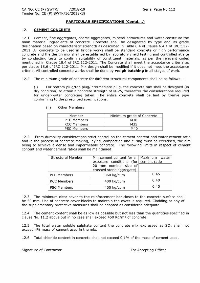
CA NO. CE (P) SWTK/ /2018-19 Serial Page No 112
Tender No. CE (P) SWTK/16/2018-19
PARTICULAR SPECIFICATIONS (Contd….)
12. CEMENT CONCRETE
12.1 Cement, fine aggregates, coarse aggregates, mineral admixtures and water constitute the
main material ingredients of concrete. Concrete shall be designated by type and its grade
designation based on characteristic strength as described in Table 6.4 of Clause 6.4.1 of IRC:112-
2011. All concrete to be used in bridge works shall be standard concrete or high performance
concrete and the design mix shall be established by laboratory /field testing and controlled at site
by conducting tests to confirm suitability of constituent materials, as per the relevant codes
mentioned in Clause 18.4 of IRC:112-2011. The Concrete shall meet the acceptance criteria as
per clause 18.6 of IRC:112-2011. Mix design shall be modified if it does not meet the acceptance
criteria. All controlled concrete works shall be done by weigh batching in all stages of work.
12.2. The minimum grade of concrete for different structural components shall be as follows: -
(i) For bottom plug/top plug/intermediate plug, the concrete mix shall be designed (in
dry condition) to attain a concrete strength of M-25, thereafter the considerations required
for under-water concreting taken. The entire concrete shall be laid by tremie pipe
conforming to the prescribed specifications.
(ii) Other Members
Member Minimum grade of Concrete
PCC Members M30
RCC Members M35
PSC Members M40
12.2 From durability considerations strict control on the cement content and water cement ratio
and in the process of concrete making, laying, compaction and curing must be exercised, the aim
being to achieve a dense and impermeable concrete. The following limits in respect of cement
content and water cement ratios shall be maintained:
Structural Member Min cement content for all
exposure conditions (for
20 mm nominal size of
crushed stone aggregate)
Maximum water
cement ratio
PCC Members 360 kg/cum 0.45
RCC Members 400 kg/cum 0.40
PSC Members 400 kg/cum 0.40
12.3 The minimum clear cover to the reinforcement bar closes to the concrete surface shall
be 50 mm. Use of concrete cover blocks to maintain the cover is required. Cladding or any of
the supplementary protective measures shall be adopted as considered adequate.
12.4 The cement content shall be as low as possible but not less than the quantities specified in
clause No. 11.2 above but in no case shall exceed 450 Kg/m³ of concrete.
12.5 The total water soluble sulphate content the concrete mix expressed as SO3 shall not
exceed 4% mass of cement used in the mix.
12.6 Total chloride content in concrete shall not exceed 0.1% of the mass of cement used.
Signature of Contractor For Accepting Officer
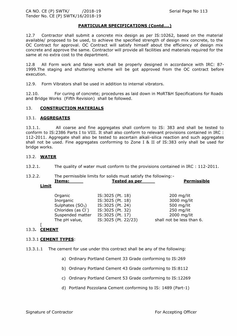
CA NO. CE (P) SWTK/ /2018-19 Serial Page No 113
Tender No. CE (P) SWTK/16/2018-19
PARTICULAR SPECIFICATIONS (Contd….)
12.7 Contractor shall submit a concrete mix design as per IS:10262, based on the material
available/ proposed to be used, to achieve the specified strength of design mix concrete, to the
OC Contract for approval. OC Contract will satisfy himself about the efficiency of design mix
concrete and approve the same. Contractor will provide all facilities and materials required for the
same at no extra cost to the department.
12.8 All Form work and false work shall be properly designed in accordance with IRC: 87-
1999.The staging and shuttering scheme will be got approved from the OC contract before
execution.
12.9. Form Vibrators shall be used in addition to internal vibrators.
12.10. For curing of concrete; procedures as laid down in MoRT&H Specifications for Roads
and Bridge Works (Fifth Revision) shall be followed.
13. CONSTRUCTION MATERIALS
13.1. AGGREGATES
13.1.1. All coarse and fine aggregates shall conform to IS: 383 and shall be tested to
conform to IS:2386 Parts I to VIII. It shall also conform to relevant provisions contained in IRC :
112-2011. Aggregate shall also be tested to ascertain alkali-silica reaction and such aggregates
shall not be used. Fine aggregates conforming to Zone I & II of IS:383 only shall be used for
bridge works.
13.2. WATER
13.2.1. The quality of water must conform to the provisions contained in IRC : 112-2011.
13.2.2. The permissible limits for solids must satisfy the following:-
Items: Tested as per Permissible
Limit
Organic IS:3025 (Pt. 18) 200 mg/lit
Inorganic IS:3025 (Pt. 18) 3000 mg/lit
Sulphates (SO3) IS:3025 (Pt. 24) 500 mg/lit
Chlorides (as Cl-) IS:3025 (Pt. 32) 250 mg/lit
Suspended matter IS:3025 (Pt. 17) 2000 mg/lit
The pH value, IS:3025 (Pt. 22/23) shall not be less than 6.
[
13.3. CEMENT
13.3.1 CEMENT TYPES:
13.3.1.1 The cement for use under this contract shall be any of the following:
a) Ordinary Portland Cement 33 Grade conforming to IS:269
b) Ordinary Portland Cement 43 Grade conforming to IS:8112
c) Ordinary Portland Cement 53 Grade conforming to IS:12269
d) Portland Pozzolana Cement conforming to IS: 1489 (Part-1)
Signature of Contractor For Accepting Officer
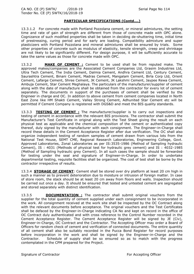
CA NO. CE (P) SWTK/ /2018-19 Serial Page No 114
Tender No. CE (P) SWTK/16/2018-19
PARTICULAR SPECIFICATIONS (Contd….)
13.3.1.2 For concrete made with Portland Pozzolana cement, or mineral admixtures, the setting
time and rate of gain of strength are different from those of concrete made with OPC alone.
Cognizance of such modified properties shall be taken in deciding de-shuttering time, initial time
of prestressing, curing period and for early are loading. Compatibility admixture and super
plasticizers with Portland Pozzolana and mineral admixtures shall be ensured by trials. Some
other properties of concrete such as modulus of elasticity, tensile strength, creep and shrinkage
are not likely to be significantly different. For design purpose, it will be sufficiently accurate to
take the same values as those for concrete made with OPC.
13.3.2 MAKE OF CEMENT : Cement to be used shall be from reputed make. The
approved makes/companies are the Associated Cement Companies Ltd, Grasim Industries Ltd,
Ultra Tech Cement, The India Cement, Dalmia Cement, Andhra Cement Ltd, Century Cement,
Saurashtra Cement, Binani Cement, Madras Cement, Mangalam Cement, Birla Corp Ltd, Orient
Cement, Lafarge Cement, Shree Cement, JK Cement, JK Lakshmi Cement, Jaypee Rewa Cement,
Ambuja Cement, Star Cement Meghalaya. The particulars of the manufacturer/supplier of cement
along with the date of manufacture shall be obtained from the contractor for every lot of cement
separately. The documents in support of the purchases of cement shall be verified by the
Engineer in charge and OC. In addition to above cement from cement companies located in North
East Zone like HM Shakti Cement, Valley Strong Cement, Adhunited Star Cement etc will be
permitted if Cement Company is registered with DGS&D and meet the BIS quality standards.
13.3.3 TESTING OF CEMENT : The manufacturer/supplier is to carry out inspections and
testing of cement in accordance with the relevant BIS provisions. The contractor shall submit the
Manufacturer‟s Test Certificate in original along with the Test Sheet giving the result on each
physical test as applicable and the chemical composition of the cement or authenticated copy
thereof, duly signed by the manufacturer with each consignment. The Engineer-in-Charge shall
record these details in the Cement Acceptance Register after due verification. The OC shall also
organize independent testing of random samples of cement drawn from various lots from the
National Test House, SEMT CME, Regional Research Laboratories, Engineering College, Govt.
Approved Laboratories, Zonal Laboratories as per IS:3535-1986 (Method of Sampling hydraulic
Cement), IS : 4031 (Methods of physical test for hydraulic grey cement) and IS : 4032-1985
(Method of Sampling hydraulic grey Cement). In all such cases the sample should be forwarded
for testing under the seal and signature of Engineer-in-Charge. In order to undertake
departmental testing, requisite facilities shall be organized. The cost of test shall be borne by the
contractor irrespective of results.
13.3.4 STORAGE OF CEMENT: Cement shall be stored over dry platform at least 20 cm high in
such a manner as to prevent deterioration due to moisture or intrusion of foreign matter. In case
of store room, the stack should be at least 20 cm away from floors and walls. Inspection should
be carried out once a day. It should be ensured that tested and untested cement are segregated
and stored separately with distinct identification.
13.3.5 DOCUMENTATION : The contractor shall submit original vouchers from the
supplier for the total quantity of cement supplied under each consignment to be incorporated in
the work. All consignment received at the work site shall be inspected by the OC Contract along
with the relevant documents before acceptance. The original vouchers and the Test Certificates
shall be defaced by the Engineer-in-Charge indicating CA No and kept on record in the office of
OC Contract duly authenticated and with cross reference to the Control Number recorded in the
Cement Acceptance Register. The Cement Acceptance Register will be signed by JE (Civ),
Engineer-in-Charge, OC Contract and the Contractor. The Accepting Officer may order a Board of
Officers for random check of cement and verification of connected documents. The entire quantity
of all cement shall also be suitably recorded in the Pucca Bond Register for record purposes
before incorporation in the work and shall be signed by the Engineer-in-Charge and the
Contractor. Schedule of supply shall be so ensured so as to match with the progress
contemplated in the CPM prepared for the Project.
Signature of Contractor For Accepting Officer
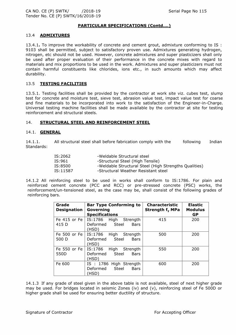
CA NO. CE (P) SWTK/ /2018-19 Serial Page No 115
Tender No. CE (P) SWTK/16/2018-19
PARTICULAR SPECIFICATIONS (Contd….)
13.4 ADMIXTURES
13.4.1. To improve the workability of concrete and cement grout, admixture conforming to IS :
9103 shall be permitted, subject to satisfactory proven use. Admixtures generating hydrogen,
nitrogen, etc should not be used. However, concrete admixtures and super plasticizers shall only
be used after proper evaluation of their performance in the concrete mixes with regard to
materials and mix proportions to be used in the work. Admixtures and super plasticizers must not
contain harmful constituents like chlorides, ions etc., in such amounts which may affect
durability.
13.5 TESTING FACILITIES
13.5.1. Testing facilities shall be provided by the contractor at work site viz. cubes test, slump
test for concrete and moisture test, sieve test, abrasion value test, impact value test for coarse
and fine materials to be incorporated into work to the satisfaction of the Engineer-in-Charge.
Universal testing machine facilities shall be made available by the contractor at site for testing
reinforcement and structural steels.
14. STRUCTURAL STEEL AND REINFORCEMENT STEEL
14.1. GENERAL
14.1.1. All structural steel shall before fabrication comply with the following Indian
Standards:
IS:2062 -Weldable Structural steel
IS:961 -Structural Steel (High Tensile)
IS:8500 -Weldable Structural Steel (High Strengths Qualities)
IS:11587 -Structural Weather Resistant steel
14.1.2 All reinforcing steel to be used in works shall conform to IS:1786. For plain and
reinforced cement concrete (PCC and RCC) or pre-stressed concrete (PSC) works, the
reinforcement/un-tensioned steel, as the case may be, shall consist of the following grades of
reinforcing bars.
Grade
Designation
Bar Type Conforming to
Governing
Specifications
Characteristic
Strength fy MPa
Elastic
Modulus
GP
Fe 415 or Fe
415 D
IS:1786 High Strength
Deformed Steel Bars
(HSD)
415 200
Fe 500 or Fe
500 D
IS:1786 High Strength
Deformed Steel Bars
(HSD)
500 200
Fe 550 or Fe
550D
IS:1786 High Strength
Deformed Steel Bars
(HSD)
550 200
Fe 600 IS : 1786 High Strength
Deformed Steel Bars
(HSD)
600 200
14.1.3 If any grade of steel given in the above table is not available, steel of next higher grade
may be used. For bridges located in seismic Zones (iv) and (v), reinforcing steel of Fe 500D or
higher grade shall be used for ensuring better ductility of structure.
Signature of Contractor For Accepting Officer
CA NO. CE (P) SWTK/ /2018-19 Serial Page No 116
Tender No. CE (P) SWTK/16/2018-19
PARTICULAR SPECIFICATIONS (Contd….)
14.1.4. Hot dipped galvanized reinforcing steel shall be provided wherever specified. The
coating shall conform to IS: 12594-1988.
14.2. FABRICATION
14.2.1. All works shall be done in accordance with approved drawings and laid down
specifications. It shall be ensured that all parts of an assembly fit together. All members shall
carry mark number and item number and, if required, serial number. Method of marking shall be
commensurate with the process of manufacture and such as to ensure retention of identity at all
stages. The parts shall be match marked.
14.2.2. The Contractor shall submit his programme of fabrication work to the OC Contract
for his approval at least 15 days before the planned commencement. This programme shall
include the proposed system of identification and erection marks together with the complete
detail of fabrication and welding procedures. Contractor shall also submit for approval of OC
Contract, a Quality Assurance Plan according to the nature of fabrication work (whether welded,
bolted or riveted) which should clearly define the points of checking and inspection during the
stages of fabrication as well as supply of materials.
14.3. ERECTION:
14.3.1. The Contractor shall submit to the OC Contract a detailed erection scheme showing
stage wise activities with complete drawings and working phase wise instructions. The erection
scheme shall be in strict conformity to the assumptions made in structural design of the bridge
superstructure. This is to be based on detail stage wise calculation and take into account
specification and capacity of erection equipments, machinery, tools, tackles to be used and
temporary working loads as per codal provisions.
14.3.2. The scheme shall also take into account site conditions such as hydrology, rainfall,
flood timings and intensity, soil and sub soil conditions in the river bed and bank, maximum
water depth, temperature and climatic conditions and available working space.
14.3.3. Before starting work, the contractor shall obtain necessary approval of the
accepting officer as to the method adopted for erection, the number and the character of tools
and plants. The approval of the accepting officer shall however not relieve the contractor of his
responsibility for the safety of his method or equipment or from carrying out the work fully and in
accordance with the drawings and specification.
14.4. HANDLING AND STORAGE OF STEEL: All material, consumables, including raw steel or
fabricated material shall be stored specification wise and size wise above the ground upon leveled
platforms, skids or other supports. They shall be kept free from dirt and other foreign matters
and shall be protected from corrosion and distortion. The electrodes shall be stored specification
wise and shall be kept in dry warm conditions in properly designed racks. The bolts, nuts,
washers and other fasteners shall be stored in gunny bags on racks above the ground with
protective oil coating. in gunny bags.
14.5 STRAIGHTENING AND BENDING OF MATERIAL
14.5.1. The straightening of plates, angles and other shapes shall be done by methods not
likely to produce fracture or any injury. Hammering shall not be permitted. Heating of metal, if
permitted by OC Contract for special cases, shall be followed by as slow cooling as possible.
Straightening by heating shall be done under controlled procedure and temperature of the steel
shall not be more than 650OC. Heating and cooling rate shall be appropriate to the particular type
of steel and shall be as agreed and approved by OC Contract. Accelerated cooling shall not be
permitted.
Signature of Contractor For Accepting Officer
CA NO. CE (P) SWTK/ /2018-19 Serial Page No 117
Tender No. CE (P) SWTK/16/2018-19
PARTICULAR SPECIFICATIONS (Contd….)
14.5.2. Following the straightening of a bend or buckle, the surface shall be carefully
inspected for evidence of fracture. Members having sharp kinks and bends shall be rejected.
14.6 SHOP ERECTION AND MATCH MARKING
14.6.1. Before being dispatched, the steel work shall be temporarily erected in the fabrication
shop for inspection by the Engineer-in-Charge either wholly or in such portion as the Engineer-in-
Charge may require so that he may be satisfied both in respect of the alignment and fit of all
connections. For this purpose, sufficient number of parallel drifts and service bolts screwed up
shall be employed. All parts shall fit accurately and be in accordance with drawing and
specifications.
14.6.2. The camber diagram showing camber at each panel point, method of shop
assembly and any other relevant detail shall be submitted to Engineer-in-charge for approval.
14.6.3. The field connections of main members of trusses ,arches, continuous beams,
spans, bends, plate girders and rigid frame shall be assembled, aligned and accuracy of holes and
camber checked by the Engineer-in-charge. Only thereafter shall reaming of sub-sized holes to
specified size, be taken up.
14.6.3 The assembly shall be dismantled only after final drilling of holes has been completed and
the work has been passed by the Engineer-in-charge. Before dismantling, each part shall be
carefully marked for re-erection with distinguishing marks and stamped with durable markings.
Drawings showing these markings correctly shall be supplied to the Engineer-in-charge.
14.7. FIELD INSPECTION:
14.7.1. No protective treatment shall be applied to the work until the appropriate inspection and
testing is carried out by Engineer-in-Charge and OC Contract. The stage inspection shall be
carried out for all operations so as to ensure the correctness of fabrication and good quality.
Girder dimensions and camber shall not be finally checked until all welding and heating
operations are completed and the members had cooled to a uniform temperature.
14.8. TESTING
14.8.1. Structural Steel shall be tested for mechanical and chemical properties as per
various IS codes as may be applicable and shall conform to the requirements specified in
IS:2062, IS: 11587, IS: 8500 and IS: 961.
14.8.2. The reinforcing steel shall be tested to conform to requirements of IS:1786.
14.8.3. Bolts and bolted connection joints with HSFG bolts shall be inspected and tested
according to IS:4000.
14.8.4. Rivets and rivet bolts shall be inspected as per Clause 1904.6 of MoRTH
Specifications for Roads & Bridge Works(Fifth revision) and tested for compliance of codal
requirements.
14.8.5. Welding procedure, welded connections and testing shall be in compliance with
codal requirements. All facilities necessary for stage inspection during welding and on completion
shall be provided to the OC Contract or his inspecting authority by contractor/fabricator.
14.9. PROCUREMENT:
Signature of Contractor For Accepting Officer
CA NO. CE (P) SWTK/ /2018-19 Serial Page No 118
Tender No. CE (P) SWTK/16/2018-19
PARTICULAR SPECIFICATIONS (Contd….)
14.9.1. All structural steel/ reinforcement shall be procured by the contractor directly from SAIL,
TISCO, RINL (Vizag Steel), Essar Steel Ltd, Lloyds Steel Industries Ltd, Jindal Iron and Steel Co.
Ltd, Jindal Vijay Nagar Steel Ltd, IISCO, Jindal Strips Ltd, and Trade Arbed. On Receipt of the
consignment of steel at the fabrication yard, the contractor shall inform the same verbally as well
as in writing to the OC Contract within a week based on which the OC Contract shall depute the
engineer-in-Charge to the fabrication yard for inspection, testing and approval of the lot for
fabrication with respect to its quality and the grade as per tender stipulation, and stamping with
the departmental insignia. The contractor shall also submit the original copy of invoice along
with the manufacturer‟s test certificate to the Engineer-in-Charge during his inspection. On
arrival of fabricated components at site, the same shall be verified by the Engineer-in-Charge and
the OC contract and approved for incorporation in the structure.
14.9.2. Only new steel shall be delivered to the site. Every bar shall be inspected before
assembling on the work and defective, brittle or burnt bars shall be discarded. Bars with cracked
ends shall be discarded. For the steel procured from original producers also, the
Engineer/Employer may carry out occasional checks on materials through third party as
mentioned above, for confirming the test results shown in the certificates, in case of any doubt
regarding the quality of steel supplied.
15. APPROVAL OF DESIGNS
15.1 On opening of financial bid, the lowest tenderer on receipt of acceptance letter from the
accepting officer should ensure submission of details, design calculations and supported working
drawings for all structures based on provisions made in this tender document, various codes and
sound engineering design and construction practice within 60 days from the date of receipt of
acceptance letter to Bridge & Tunnel Dte/HQ DGBR who will examine the details, drawings &
design calculations submitted by the contractor for its adequacy with respect to contract
provisions and codal stipulations and make modifications as deemed fit. The contractor shall be
bound to make all such modifications in the said details, drawings and calculations as the DDG (B
& T) of HQ DGBR, New Delhi may consider necessary, so as to comply the standard code and
specifications mentioned in these or in their absence to comply with the accepted principles of
sound engineering practice. Outcome of scrutiny of drawings, design/specifications and or
comments thereon will be communicated to the contractor by the officer duly authorized by the
DDG (Br & Tnl) of HQ DGBR. After complying with observations/comments/modifications
communicated as above, the Contractor shall resubmit the detail and design drawings duly proof
checked by Indian Institute of Technology (IIT) to B & T Dte of HQ DGBR, New Delhi where the
same shall be re-examined by DDG (B & T) and Approval accorded. Approval(s) to drawings,
design/specifications and or comments thereon will be communicated to the contractor by the
officer duly authorized by the DDG (B & T) of HQ DGBR. In the event of any disputes arising as
whether any modifications are necessary or not, the decision of the DDG (B & T) of HQ DGBR
shall be final and binding. If as a result of the scrutiny of afore described, any modifications in the
contractor‟s drawings and calculations etc are rendered necessary in order to ensure that the
designs are safe and comply with the various requirements laid down in these contract
documents, the contractor shall not be entitled to any extra payment on this account. On receipt
of communication regarding approval to the contractor‟s design and calculations, the contractor
shall supply to the B & T Dte of HQ DGBR within a period of 15 days of the receipt of such
communications, sixteen copies of the approved drawings for use by the department. The work on
construction of the bridge(s) shall proceed as per the approved detailed working drawings.
Signature of Contractor For Accepting Officer
CA NO. CE (P) SWTK/ /2018-19 Serial Page No 119
Tender No. CE (P) SWTK/16/2018-19
PARTICULAR SPECIFICATIONS (Contd….)
15.2 During the currency of the work in case any changes are required in the approved design
due to ground conditions or any technical reasons, the contractor shall submit the complete
detailed working drawings and design calculations in respect of such changes of the bridge for
technical scrutiny to the Bridge & Tunnel Dte of HQ DGBR. The details, drawing and design
calculations for such changes as and when submitted by the contractor will be examined by DDG
(B & T) of HQ DGBR, New Delhi and shall be subject to his approval. The contractor shall be
bound to make all such modification in the said details, drawings and calculations as the DDG (B
& T) of HQ DGBR may consider necessary, so as to comply the standard code and specifications
mentioned in these or in their absence to comply with the accepted principles of sound
engineering practice. Preliminary Approval(s) to drawings design/specifications and or comments
thereon will be communicated to the contractor by the officer duly authorized by the DDG (B & T)
of HQ DGBR. After complying with observations/comments/modifications communicated as above,
the Contractor shall resubmit the detail and design drawings duly proof checked by Indian
Institute of Technology (IIT) to B & T Dte of HQ DGBR, New Delhi where the same shall be re-
examined by DDG (B & T) and final approval accorded. In the event of any disputes arising as
whether any modifications are necessary or not, the decision of the DDG (B & T) of HQ DGBR
shall be final and binding. If as a result of the scrutiny of afore described, any modifications in the
contractor‟s drawings and calculations etc, are rendered necessary in order to ensure that the
designs are safe and comply with the various requirements laid down in these contract
documents, the contractor shall not be entitled to any extra payment on this account. On receipt
of communication regarding approval to the contractor‟s design and calculations, the contractor
shall supply to the DGBR within a period of 15 days of the receipt of such communications,
sixteen copies of the approved drawings for use by the department. The work on construction of
the bridge(s) shall proceed as per the approved detailed working drawings.
15.3 Proof checking of the design and drawings submitted by the contractor shall be got done
by the Contractor from Indian Institute of Technology (IIT) at his own cost. Contractor‟s
quoted lump sum amount shall be deemed to include the charges for the proof checking.
15.4. Notwithstanding the approval to the design and calculations submitted by the
contractor, the contractor shall be responsible for the stability and safely of the bridge
in accordance with the provisions of the contract and approvals accorded as herein
before stated shall not absolve him of his responsibility for the safety of the structures
designed and constructed by him.
15.5. Design folder along-with detailed calculations will be submitted in digital format (CD etc) in
original file formats i.e. Office Excel sheets, Auto CAD, Word etc. Files in PDF format shall not be
accepted. Analysis by using software will be submitted along with relevant input/output files and
explanatory notes modeling/methodology used.
15.6. All designs, calculations, drawings etc in respect of this bridge shall be the sole property of
DGBR.
16. LOAD TESTING OF BRIDGE
16.1 GENERAL
16.1.1 On completion of the work, the bridge will load tested in accordance with IRC-SP-51
: 2015. The lump sum amount quoted by the contractor for the bridge shall be
deemed to include all expenses involved in load testing of superstructure of the bridge. All
arrangements for carrying out the tests shall be made by the contractor and shall conform
to the procedure which may be laid down for the purpose by the Accepting Officer and in
accordance with IRC SP: 51 – 2015.
Signature of Contractor For Accepting Officer
CA NO. CE (P) SWTK/ /2018-19 Serial Page No 120
Tender No. CE (P) SWTK/16/2018-19
PARTICULAR SPECIFICATIONS (Contd….)
16.1.2. The Engineer-in-Charge may also instruct that a load test on any part of the
bridge structure, if in his opinion such a test is deemed necessary for any one or more of
the reasons specified below, will be carried out at no extra cost to the Deptt.
(i) The work test cubes failing to attain the specified strength.
(ii) Shuttering being prematurely removed.
(iii) Improperly cured.
(iv) Any other Circumstances attributable to the negligence on the part of the
contractor, which in the opinion of the Engineer-in-Charge results in the structure
or part there of being less than the expected Strength.
16.2 LOAD TEST SCHEME
16.2.1. The Contractor shall submit all necessary calculations and details of
arrangements for load testing of the bridge which shall include the magnitude of the test
load, method of carrying out the test, the application of loads, duration of keeping the
load, the deflections at each load level, the equipment to be used and observation to be
made during and after placing the loads in position etc., as per IRC SP: 51 – 2015 to Br &
Tnl Dte/HQ DGBR. The Br & Tnl Dte, after examination, will convey their comments
thereon to the Contractor who will comply with the same and resubmit load testing
scheme and calculations duly proof checked from IIT. Thereafter, approval of DDG (B & T)
of HQ DGBR shall be conveyed to the Contractor.
16.2.2 The Contractor shall make all necessary arrangements for the observations, the
centering, staging, equipments, etc. that may be needed for measuring the settlements,
deflection etc., required for the test to the entire satisfaction of the Engineer-in-Charge,
and provide labour, and make all observations during the test.
16.3 MEASUREMENT OF DEFLECTIONS
16.3.1. Deflection shall be measured at critical locations as decided by the
Engineer-in-Charge by means of the dial gauges fixed on firm supports, independent of
the structure to be tested.
16.4 MONITORING OF TEMPERATURE EFFECTS
16.4.1. Prior to conducting actual load test, the deflection values and ambient
temperature data shall be collected from dawn to dusk for two or three consecutive days
at one hour intervals. Temperature vs deflection data collected on these days and a curve
drawn for each dial gauge location shall be taken as the basic temperature correction. The
temperature – deflection characteristics will be a linear line drawn between points of
minimum temperature-least deflection and maximum temperature-most deflection. The
deflection reading at any location and temperature during load test is superimposed on
the basic curve. The difference between the two values gives the true deflection for the
location under reference corresponding to the same temperature.
16.5 TEST PROCEDURE
16.5.1 The load test shall be done during such period of the day when the variation in
temperature is least. Preferably this should be during the early hours of day.
Signature of Contractor For Accepting Officer
CA NO. CE (P) SWTK/ /2018-19 Serial Page No 121
Tender No. CE (P) SWTK/16/2018-19
PARTICULAR SPECIFICATIONS (Contd….)
16.5.2 Prior to load testing, the superstructure of the span to be tested shall thoroughly
be examined for any signs of distress (such as any existing hair cracks etc.) and
marked/recorded so as to differentiate them from any distress that may occur during the
load test. These signs of distress shall be closely watched during the test.
16.5.3 The position of the wheels for the critical vehicle and worst positioning on
the deck shall be predetermined and indicated. The initial observations without load shall
be observed.
16.5.4 The test load shall be applied to the structure at the predetermined position by
increments as prescribed in the IRC guidelines. The load shall be applied in a minimum of
time with an interval of only five minutes between load stages for purpose of deflection
readings.
16.5.5 The deflection shall be observed at every load stage and in the final loaded
position. Corresponding ambient temperature shall also be measured.
16.5.6 The load shall then be removed by decrements as prescribed in the IRC guidelines
after a test load retention period of minimum 24 hours and record of deflections made and
temperature as before.
16.5.7 Should there be any doubt about the observations made during a load test, the
process of loading and unloading in stages with deflection observations shall be repeated.
16.6 CRITERIA OF ACCEPTANCE
(a) The load test results, if found satisfactory, shall be accepted and approved by the
Accepting Officer.
(b) The load test shall be treated as satisfactory, if
(i) The actual deflections are equal to or less than the theoretical deflections.
(ii) The recovery of deflections on removal of load is not less than 85%.
(iii) The bridge structure shows no signs of distress or defects during the load
tests.
16.7 Any defect noticed in the structure or any damage done to the bridge at the time of
testing which affects or is likely to affect the strength of the bridge shall be rectified by the
contractor at his own cost by remedial measures or replacement as approved by the Engineer-in-
Charge/OC Contract.
16.8 When the tests are declared by the Engineer-in-Charge as having been completed, the
contractor shall remove all loading which might still be on the bridge as well as on the
surroundings.
17 PAINTING
17.1. With a view to provide protection against corrosion, all exposed steel work shall be
protected by a minimum three coats of paint. The Coating System No.6 as given in Table D-2 of
Annex-D of IRC:24-2010, which has a desired life over 20 years shall be adopted for painting the
steel work in this contract. Necessary guidance shall be taken from Section 1906 of MoRTH
Specifications for Road and Bridge works (Fifth Revision). The painting shall consist of a primary
coat of paint or shop coat before erection at site. After erection, the surface shall be given two
more coats of paint, one under coat followed by a finishing coat. The shade of paint shall be done
in accordance with IS:1477 (Part 1- Code of Practice for painting of ferrous metals in buildings
and allied finishes) and as per IRC:24-2010. Alternatively, painting with paints using Nano-
technology providing effect equivalent to Coating System 6 of IRC:24-2010 or better can also be
used with approval of accepting officer.
Signature of Contractor For Accepting Officer
CA NO. CE (P) SWTK/ /2018-19 Serial Page No 122
Tender No. CE (P) SWTK/16/2018-19
PARTICULAR SPECIFICATIONS (Contd….)
18. AESTHETIC APPEARANCE
18.1 The structure shall be made aesthetically matching with surrounding and to the complete
satisfaction of the Accepting Officer.
19 COMPLETION DRAWINGS AND PHOTOGRAPHIC RECORD
19.1 On completion of construction the contractor shall supply three sets of all the completion
drawings, duly approved and properly bound, as per which the bridge has been constructed, to
the Accepting Officer for reference and record.
19.2 The contractor shall also supply three sets of photographs along with the films of all such
important activities duly put in good albums, to the accepting officer for record purpose.
20. CODES OF PRACTICE
20.1 The design of the bridge and its construction shall be in strict conformity with the
following codes of practices specification and standards:-
a) IRC: 5 - 2015 – Indian Roads Congress standard specification and code of
practice for road bridges Section-I, as applicable to General features of design.
b) IRC: 6 - 2017 - Indian Roads Congress standard specification and code of
practice for road Bridges Section-II, as applicable to load and stresses.
c) IRC: 22-2008– Indian Roads Congress Standard Specification and code of
practice for Road Bridges Section VI, applicable for composite construction for road
bridges .
d) IRC: 24-2010 - Indian roads congress standard specifications and codes of
practice for road bridges section V, steel road bridges.
e) IRC: 45-1972 – Recommendations for estimating the resistance of soil below
the maximum scour level in the design of well foundation of bridges.
f) IRC: 78-2014 – Indian Roads Congress Standard specification and code of
practice for Road Bridges Section VII, applicable for foundation and substructure.
g) IRC-83: 1987 - Standard specifications and code of practice for road bridges
section IX/bearing/Part II- Elastomeric bearings.
h) IRC-83: 2002 - Standard specifications and code of practice for road bridges
section IX/bearing/Part III- POT,POT-CUM-PTFE, Pin and metallic Guide bearings.
j) IRC: 112 -2011- Indian Roads Congress Code of practice for Concrete road
bridges. Item not covered by this code will be governed by the Indian Standard Code of
practice for pre-stressed concrete IS:1343 & Plain and reinforced concrete IS:456-2000.
k) IRC: SP : 47 – 1998 – Guide lines on quality systems of road bridges.
l) IRC : SP : 51 – 2015 – Guide lines for load testing of bridges.
m) IRC : SP : 40 – 1993 – Guide lines on techniques for strengthening and
rehabilitation of bridges.
n) IRC: SP: 37 – 2010 – Guide lines for evaluation of load carrying capacity of
bridges.
Signature of Contractor For Accepting Officer
CA NO. CE (P) SWTK/ /2018-19 Serial Page No 123
Tender No. CE (P) SWTK/16/2018-19
PARTICULAR SPECIFICATIONS (Contd….)
o) IRC:SP-69-2005-Guidelines & Specifications for Expansion Joints.
p) IS:6066-1994 – Recommendation for pressure grouting of work foundation in
river valley projects for all grouting and cable in charge works.
q) IS:1893-2002 - Criteria for earth-quake resistant design of structure (third
revision).
r) IS:2911-2010 - Code of practices for design and construction of pile foundations.
s) IS:800 –2007 - General Construction in Steel-Code of Practice
t) IS:456- 2000 - Plain and Reinforced Concrete-Code of practice
u) IS:1786-2000 - Specifications for HYSD Steel
v) IS:2062-2011 - Hot Rolled Medium and High Tensile Structural Steel
w) IS:14268 - Uncoated stress relieved strands of low relaxation
x) Ministry of Road Transport & Highways Specification for Road and bridge
works 2013 (Fifth Revision).
20.2 Any Standard specifications for criteria for road bridges, other than those specified above
that may have been published by the Indian Roads Congress and in vogue prior to the date of
issue of tenders shall also apply.
20.3 Any amendment issued to the standard specifications prior to the date of issue of
tenders shall also be applicable.
20.4 In the event of conflict between the provisions of the departmental specifications and the
IRC/BIS publication mentioned above, the severe case shall prevail.
20.5 For design, materials, specifications and construction procedures not covered by the Indian
Codes, relevant Foreign Codes may be followed with approval of the department.
20.6. Whenever any issue raised is not catered for in any of the above codes, principles of sound
engineering practice shall be followed in matters of design and construction and the decision of
the Accepting Officer shall be final and binding of all such issues.
20.7. One complete set of codes, standards and other specifications will be kept by the Contractor
at each bridge site.
20.8. Latest edition of relevant IRC/IS/BS codes shall be referred over old edition
IRC/IS/BS codes wherever applicable as per discretion of Accepting Officer.
Signature of Contractor For Accepting Officer
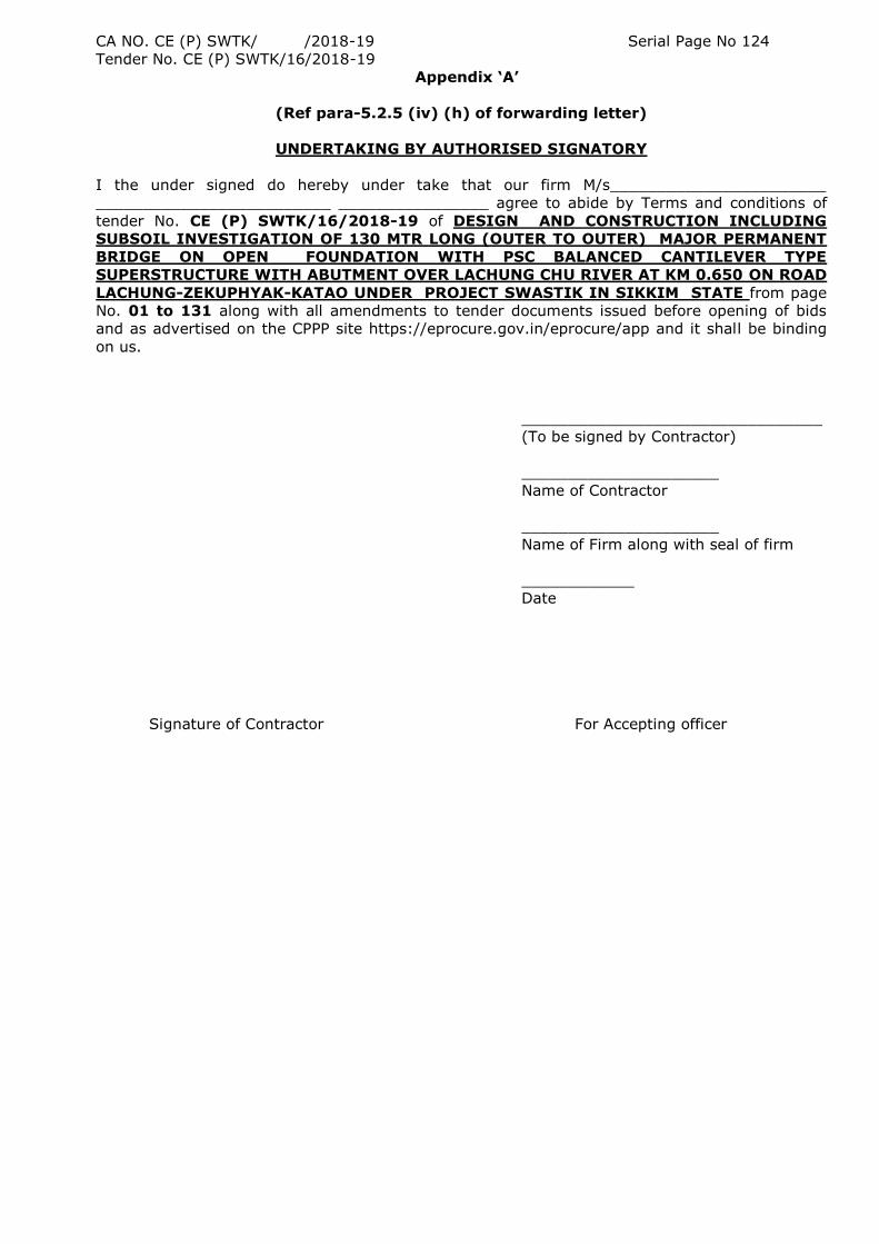
CA NO. CE (P) SWTK/ /2018-19 Serial Page No 124
Tender No. CE (P) SWTK/16/2018-19
Appendix „A‟
(Ref para-5.2.5 (iv) (h) of forwarding letter)
UNDERTAKING BY AUTHORISED SIGNATORY
I the under signed do hereby under take that our firm M/s_______________________
_________________________ ________________ agree to abide by Terms and conditions of
tender No. CE (P) SWTK/16/2018-19 of DESIGN AND CONSTRUCTION INCLUDING
SUBSOIL INVESTIGATION OF 130 MTR LONG (OUTER TO OUTER) MAJOR PERMANENT
BRIDGE ON OPEN FOUNDATION WITH PSC BALANCED CANTILEVER TYPE
SUPERSTRUCTURE WITH ABUTMENT OVER LACHUNG CHU RIVER AT KM 0.650 ON ROAD
LACHUNG-ZEKUPHYAK-KATAO UNDER PROJECT SWASTIK IN SIKKIM STATE from page
No. 01 to 131 along with all amendments to tender documents issued before opening of bids
and as advertised on the CPPP site https://eprocure.gov.in/eprocure/app and it shall be binding
on us.
________________________________
(To be signed by Contractor)
_____________________
Name of Contractor
_____________________
Name of Firm along with seal of firm
____________
Date
Signature of Contractor For Accepting officer
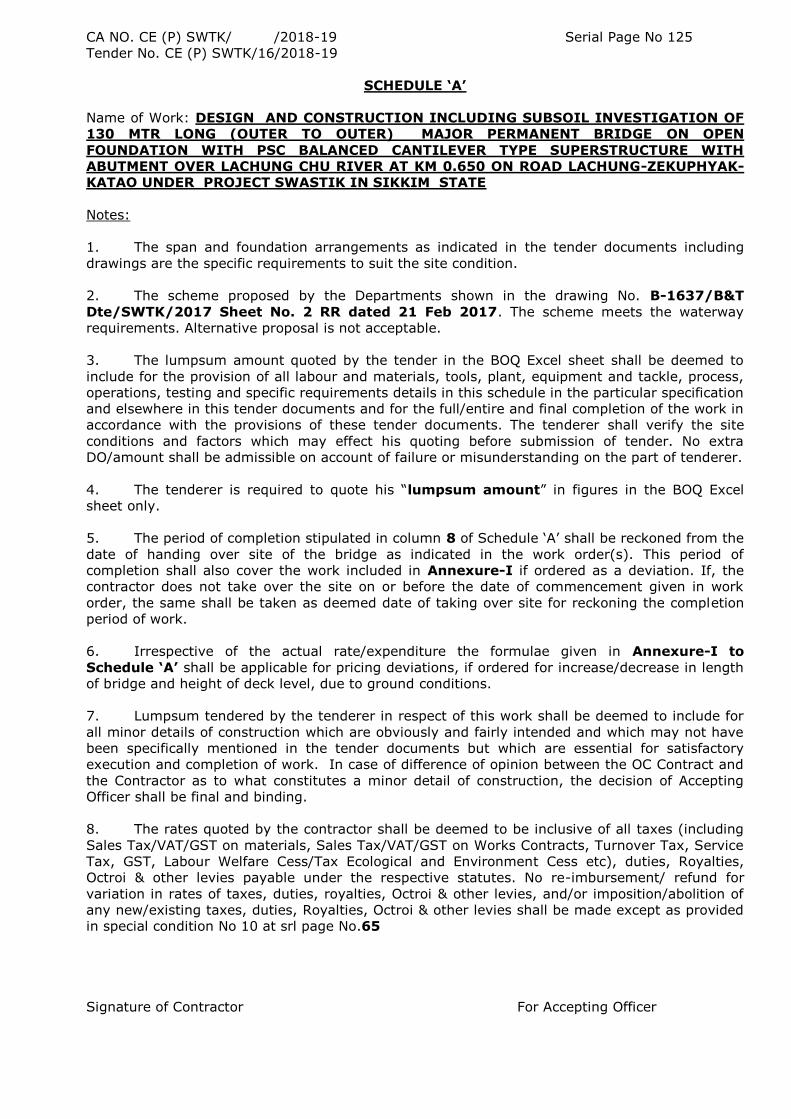
CA NO. CE (P) SWTK/ /2018-19 Serial Page No 125
Tender No. CE (P) SWTK/16/2018-19
SCHEDULE „A‟
Name of Work: DESIGN AND CONSTRUCTION INCLUDING SUBSOIL INVESTIGATION OF
130 MTR LONG (OUTER TO OUTER) MAJOR PERMANENT BRIDGE ON OPEN
FOUNDATION WITH PSC BALANCED CANTILEVER TYPE SUPERSTRUCTURE WITH
ABUTMENT OVER LACHUNG CHU RIVER AT KM 0.650 ON ROAD LACHUNG-ZEKUPHYAK-
KATAO UNDER PROJECT SWASTIK IN SIKKIM STATE
Notes:
1. The span and foundation arrangements as indicated in the tender documents including
drawings are the specific requirements to suit the site condition.
2. The scheme proposed by the Departments shown in the drawing No. B-1637/B&T
Dte/SWTK/2017 Sheet No. 2 RR dated 21 Feb 2017. The scheme meets the waterway
requirements. Alternative proposal is not acceptable.
3. The lumpsum amount quoted by the tender in the BOQ Excel sheet shall be deemed to
include for the provision of all labour and materials, tools, plant, equipment and tackle, process,
operations, testing and specific requirements details in this schedule in the particular specification
and elsewhere in this tender documents and for the full/entire and final completion of the work in
accordance with the provisions of these tender documents. The tenderer shall verify the site
conditions and factors which may effect his quoting before submission of tender. No extra
DO/amount shall be admissible on account of failure or misunderstanding on the part of tenderer.
4. The tenderer is required to quote his “lumpsum amount” in figures in the BOQ Excel
sheet only.
5. The period of completion stipulated in column 8 of Schedule „A‟ shall be reckoned from the
date of handing over site of the bridge as indicated in the work order(s). This period of
completion shall also cover the work included in Annexure-I if ordered as a deviation. If, the
contractor does not take over the site on or before the date of commencement given in work
order, the same shall be taken as deemed date of taking over site for reckoning the completion
period of work.
6. Irrespective of the actual rate/expenditure the formulae given in Annexure-I to
Schedule „A‟ shall be applicable for pricing deviations, if ordered for increase/decrease in length
of bridge and height of deck level, due to ground conditions.
7. Lumpsum tendered by the tenderer in respect of this work shall be deemed to include for
all minor details of construction which are obviously and fairly intended and which may not have
been specifically mentioned in the tender documents but which are essential for satisfactory
execution and completion of work. In case of difference of opinion between the OC Contract and
the Contractor as to what constitutes a minor detail of construction, the decision of Accepting
Officer shall be final and binding.
8. The rates quoted by the contractor shall be deemed to be inclusive of all taxes (including
Sales Tax/VAT/GST on materials, Sales Tax/VAT/GST on Works Contracts, Turnover Tax, Service
Tax, GST, Labour Welfare Cess/Tax Ecological and Environment Cess etc), duties, Royalties,
Octroi & other levies payable under the respective statutes. No re-imbursement/ refund for
variation in rates of taxes, duties, royalties, Octroi & other levies, and/or imposition/abolition of
any new/existing taxes, duties, Royalties, Octroi & other levies shall be made except as provided
in special condition No 10 at srl page No.65
Signature of Contractor For Accepting Officer
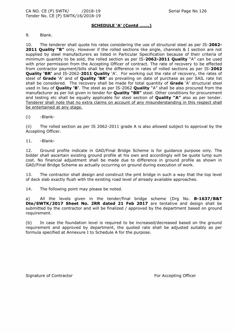
CA NO. CE (P) SWTK/ /2018-19 Serial Page No 126
Tender No. CE (P) SWTK/16/2018-19
SCHEDULE „A‟ (Contd …….)
9. Blank.
10. The tenderer shall quote his rates considering the use of structural steel as per IS-2062-
2011 Quality “B” only. However if the rolled sections like angle, channels & I section are not
supplied by steel manufacturers as listed in Particular Specification because of their criteria of
minimum quantity to be sold, the rolled section as per IS-2062-2011 Quality “A” can be used
with prior permission from the Accepting Officer of contract. The rate of recovery to be effected
from contractor payment/bills shall be the difference in rates of rolled sections as per IS-2062
Quality „BR‟ and IS-2062-2011 Quality „A‟. For working out the rate of recovery, the rates of
steel of Grade „A‟ and of Quality ‟BR‟ as prevailing on date of purchase as per SAIL rate list
shall be considered. The recovery shall be made for total quantity of Grade „A‟ structural steel
used in lieu of Quality „B‟. The steel as per IS-2062 Quality “A” shall be also procured from the
manufacturer as per list given in tender for Quality “BR” steel. Other conditions for procurement
and testing etc shall be equally applicable for steel section of Quality “A” also as per tender.
Tenderer shall note that no extra claims on account of any misunderstanding in this respect shall
be entertained at any stage.
(i) -Blank-
(ii) The rolled section as per IS 2062-2011 grade A is also allowed subject to approval by the
Accepting Officer.
11. -Blank-
12. Ground profile indicate in GAD/Final Bridge Scheme is for guidance purpose only. The
bidder shall ascertain existing ground profile at his own and accordingly will be quote lump sum
cost. No financial adjustment shall be made due to difference in ground profile as shown in
GAD/Final Bridge Scheme as actually occurring on ground during execution of work.
13. The contractor shall design and construct the pmt bridge in such a way that the top level
of deck slab exactly flush with the existing road level of already available approaches.
14. The following point may please be noted.
a) All the levels given in the tender/final bridge scheme (Drg No. B-1637/B&T
Dte/SWTK/2017 Sheet No. 2RR dated 21 Feb 2017 are tentative and design shall be
submitted by the contractor and will be finalized / approved by the department based on ground
requirement.
(b) In case the foundation level is required to be increased/decreased based on the ground
requirement and approved by department, the quoted rate shall be adjusted suitably as per
formula specified at Annexure I to Schedule A for the purpose.
Signature of Contractor For Accepting Officer
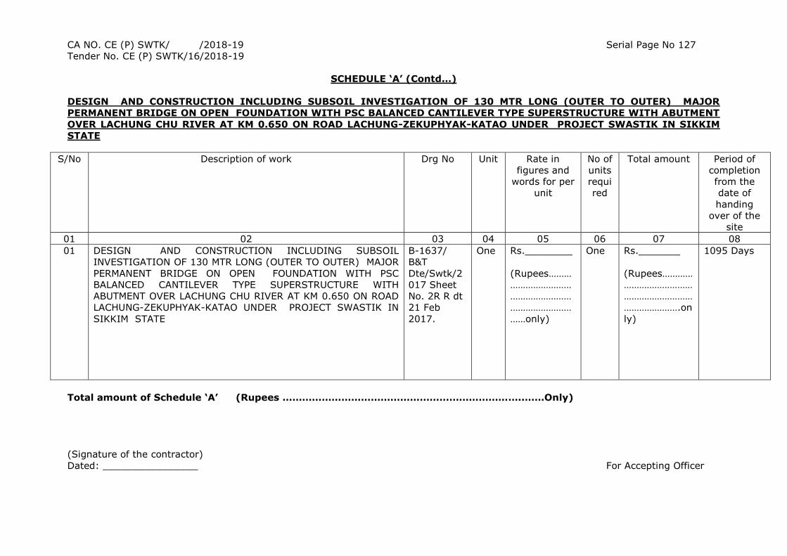
CA NO. CE (P) SWTK/ /2018-19 Serial Page No 127
Tender No. CE (P) SWTK/16/2018-19
SCHEDULE „A‟ (Contd…)
DESIGN AND CONSTRUCTION INCLUDING SUBSOIL INVESTIGATION OF 130 MTR LONG (OUTER TO OUTER) MAJOR
PERMANENT BRIDGE ON OPEN FOUNDATION WITH PSC BALANCED CANTILEVER TYPE SUPERSTRUCTURE WITH ABUTMENT
OVER LACHUNG CHU RIVER AT KM 0.650 ON ROAD LACHUNG-ZEKUPHYAK-KATAO UNDER PROJECT SWASTIK IN SIKKIM
STATE
S/No Description of work Drg No Unit Rate in
figures and
words for per
unit
No of
units
requi
red
Total amount
Period of
completion
from the
date of
handing
over of the
site
01 02 03 04 05 06 07 08
01 DESIGN AND CONSTRUCTION INCLUDING SUBSOIL
INVESTIGATION OF 130 MTR LONG (OUTER TO OUTER) MAJOR
PERMANENT BRIDGE ON OPEN FOUNDATION WITH PSC
BALANCED CANTILEVER TYPE SUPERSTRUCTURE WITH
ABUTMENT OVER LACHUNG CHU RIVER AT KM 0.650 ON ROAD
LACHUNG-ZEKUPHYAK-KATAO UNDER PROJECT SWASTIK IN
SIKKIM STATE
B-1637/
B&T
Dte/Swtk/2
017 Sheet
No. 2R R dt
21 Feb
2017.
One Rs.________
(Rupees………
……………………
……………………
……………………
……only)
One Rs._______
(Rupees…………
………………………
………………………
………………….on
ly)
1095 Days
Total amount of Schedule „A‟ (Rupees ………………………………………………………………..……Only)
(Signature of the contractor)
Dated: ________________ For Accepting Officer
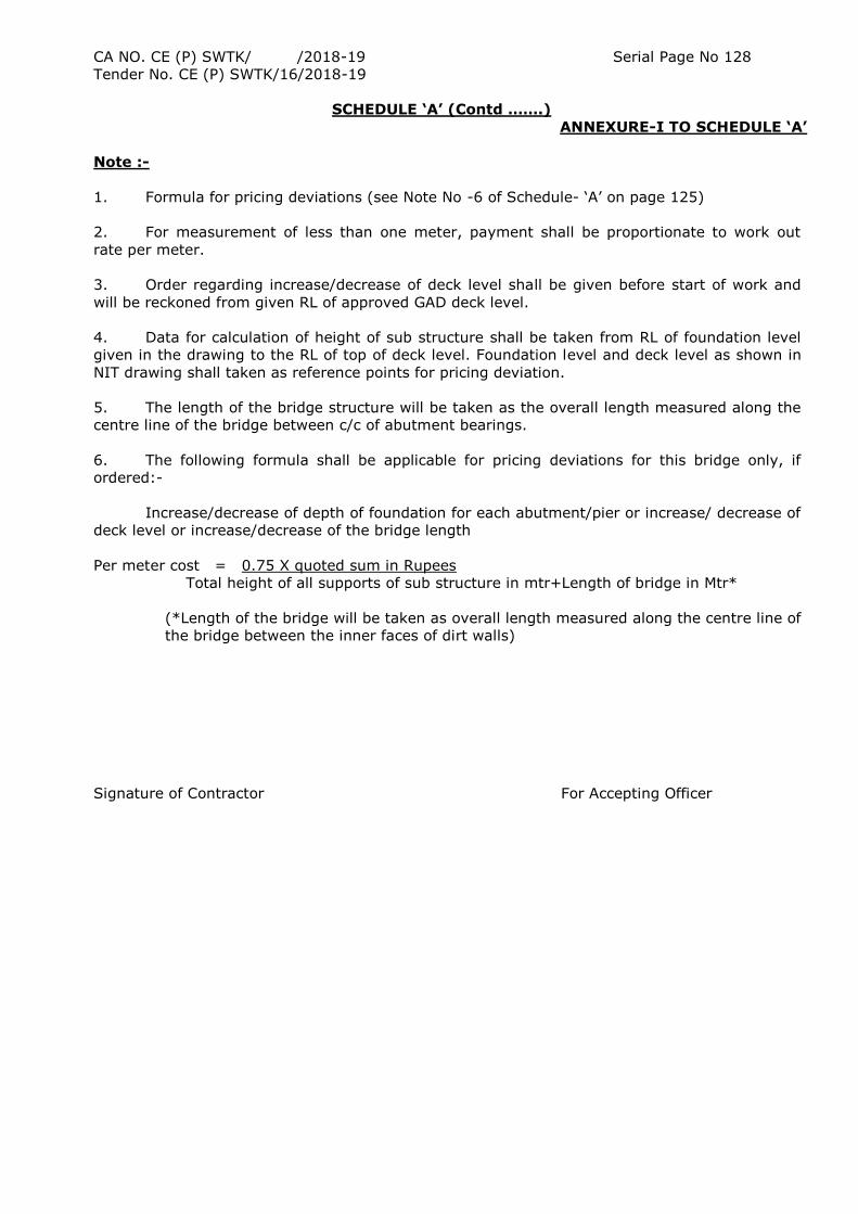
CA NO. CE (P) SWTK/ /2018-19 Serial Page No 128
Tender No. CE (P) SWTK/16/2018-19
SCHEDULE „A‟ (Contd …….)
ANNEXURE-I TO SCHEDULE „A‟
Note :-
1. Formula for pricing deviations (see Note No -6 of Schedule- „A‟ on page 125)
2. For measurement of less than one meter, payment shall be proportionate to work out
rate per meter.
3. Order regarding increase/decrease of deck level shall be given before start of work and
will be reckoned from given RL of approved GAD deck level.
4. Data for calculation of height of sub structure shall be taken from RL of foundation level
given in the drawing to the RL of top of deck level. Foundation level and deck level as shown in
NIT drawing shall taken as reference points for pricing deviation.
5. The length of the bridge structure will be taken as the overall length measured along the
centre line of the bridge between c/c of abutment bearings.
6. The following formula shall be applicable for pricing deviations for this bridge only, if
ordered:-
Increase/decrease of depth of foundation for each abutment/pier or increase/ decrease of
deck level or increase/decrease of the bridge length
Per meter cost = 0.75 X quoted sum in Rupees
Total height of all supports of sub structure in mtr+Length of bridge in Mtr*
(*Length of the bridge will be taken as overall length measured along the centre line of
the bridge between the inner faces of dirt walls)
Signature of Contractor For Accepting Officer
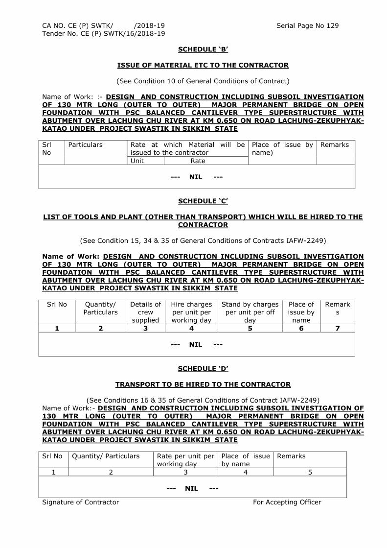
CA NO. CE (P) SWTK/ /2018-19 Serial Page No 129
Tender No. CE (P) SWTK/16/2018-19
SCHEDULE „B‟
ISSUE OF MATERIAL ETC TO THE CONTRACTOR
(See Condition 10 of General Conditions of Contract)
Name of Work: :- DESIGN AND CONSTRUCTION INCLUDING SUBSOIL INVESTIGATION
OF 130 MTR LONG (OUTER TO OUTER) MAJOR PERMANENT BRIDGE ON OPEN
FOUNDATION WITH PSC BALANCED CANTILEVER TYPE SUPERSTRUCTURE WITH
ABUTMENT OVER LACHUNG CHU RIVER AT KM 0.650 ON ROAD LACHUNG-ZEKUPHYAK-
KATAO UNDER PROJECT SWASTIK IN SIKKIM STATE
Srl
No
Particulars Rate at which Material will be
issued to the contractor
Place of issue by
name)
Remarks
Unit Rate
--- NIL ---
SCHEDULE „C‟
LIST OF TOOLS AND PLANT (OTHER THAN TRANSPORT) WHICH WILL BE HIRED TO THE
CONTRACTOR
(See Condition 15, 34 & 35 of General Conditions of Contracts IAFW-2249)
Name of Work: DESIGN AND CONSTRUCTION INCLUDING SUBSOIL INVESTIGATION
OF 130 MTR LONG (OUTER TO OUTER) MAJOR PERMANENT BRIDGE ON OPEN
FOUNDATION WITH PSC BALANCED CANTILEVER TYPE SUPERSTRUCTURE WITH
ABUTMENT OVER LACHUNG CHU RIVER AT KM 0.650 ON ROAD LACHUNG-ZEKUPHYAK-
KATAO UNDER PROJECT SWASTIK IN SIKKIM STATE
Srl No Quantity/
Particulars
Details of
crew
supplied
Hire charges
per unit per
working day
Stand by charges
per unit per off
day
Place of
issue by
name
Remark
s
1 2 3 4 5 6 7
--- NIL ---
SCHEDULE „D‟
TRANSPORT TO BE HIRED TO THE CONTRACTOR
(See Conditions 16 & 35 of General Conditions of Contract IAFW-2249)
Name of Work:- DESIGN AND CONSTRUCTION INCLUDING SUBSOIL INVESTIGATION OF
130 MTR LONG (OUTER TO OUTER) MAJOR PERMANENT BRIDGE ON OPEN
FOUNDATION WITH PSC BALANCED CANTILEVER TYPE SUPERSTRUCTURE WITH
ABUTMENT OVER LACHUNG CHU RIVER AT KM 0.650 ON ROAD LACHUNG-ZEKUPHYAK-
KATAO UNDER PROJECT SWASTIK IN SIKKIM STATE
Srl No Quantity/ Particulars Rate per unit per
working day
Place of issue
by name
Remarks
1 2 3 4 5
--- NIL ---
Signature of Contractor For Accepting Officer
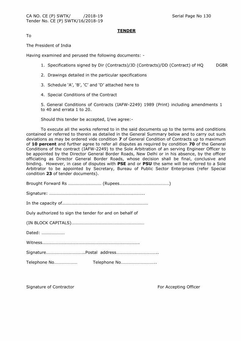
CA NO. CE (P) SWTK/ /2018-19 Serial Page No 130
Tender No. CE (P) SWTK/16/2018-19
TENDER
To
The President of India
Having examined and perused the following documents: -
1. Specifications signed by Dir (Contracts)/JD (Contracts)/DD (Contract) of HQ DGBR
2. Drawings detailed in the particular specifications
3. Schedule „A‟, „B‟, „C‟ and „D‟ attached here to
4. Special Conditions of the Contract
5. General Conditions of Contracts (IAFW-2249) 1989 (Print) including amendments 1
to 40 and errata 1 to 20.
Should this tender be accepted, I/we agree:-
To execute all the works referred to in the said documents up to the terms and conditions
contained or referred to therein as detailed in the General Summary below and to carry out such
deviations as may be ordered vide condition 7 of General Condition of Contracts up to maximum
of 10 percent and further agree to refer all disputes as required by condition 70 of the General
Conditions of the contract (IAFW-2249) to the Sole Arbitration of an serving Engineer Officer to
be appointed by the Director General Border Roads, New Delhi or in his absence, by the officer
officiating as Director General Border Roads, whose decision shall be final, conclusive and
binding. However, in case of disputes with PSE and or PSU the same will be referred to a Sole
Arbitrator to be appointed by Secretary, Bureau of Public Sector Enterprises (refer Special
condition 23 of tender documents).
Brought Forward Rs ………………………… (Rupees………………………………………)
Signature: …………………………………………………………………………..
In the capacity of……………………………………………………………………
Duly authorized to sign the tender for and on behalf of
(IN BLOCK CAPITALS)…………………………………………………………
Dated: …………………
Witness…………………………………………………………………………….
Signature……………………………..Postal address………………………………..
Telephone No………………… Telephone No…………………………..
Signature of Contractor For Accepting Officer

CA NO. CE (P) SWTK/ /2018-19 Serial Page No 131
Tender No. CE (P) SWTK/16/2018-19
ACCEPTANCE
Name of Work : DESIGN AND CONSTRUCTION INCLUDING SUBSOIL INVESTIGATION
OF 130 MTR LONG (OUTER TO OUTER) MAJOR PERMANENT BRIDGE ON OPEN
FOUNDATION WITH PSC BALANCED CANTILEVER TYPE SUPERSTRUCTURE WITH
ABUTMENT OVER LACHUNG CHU RIVER AT KM 0.650 ON ROAD LACHUNG-ZEKUPHYAK-
KATAO UNDER PROJECT SWASTIK IN SIKKIM STATE
1. ________ alterations have been made in these documents and as evidence that these
alterations were made before the execution of this contract agreement they have been initialed by
the contractor and Shri ___________________________SW / Dir (Contract) of HQ CE (P) Swastik.
2. The said officer is hereby authorized to sign and initial on my behalf the documents, forming
part of this contract, on my behalf.
3. The above tender of M/s ______________________________________
_________________________________ was accepted by me on …………… day of ……………. 2018,
on behalf of the President of India for the contract sum of
Rs________________________________________(Rupees__________________________
_____________________________________________________________________
_______only ) at the item rates quoted in Schedule “A”.
Signature __________________
(Harendra Kumar)
Chief Engineer
Project Swastik
Dated: ______________
(for and on behalf of President of India)
Signature of the Contractor For Accepting Officer