Embed Size (px)
Citation preview
9 708 069 951 Page1
Installation / Operating InstructionsGOOD.BEETER>BOSCH
BOSCH 13P & 16P
Continuous Flow Gas Water Heater
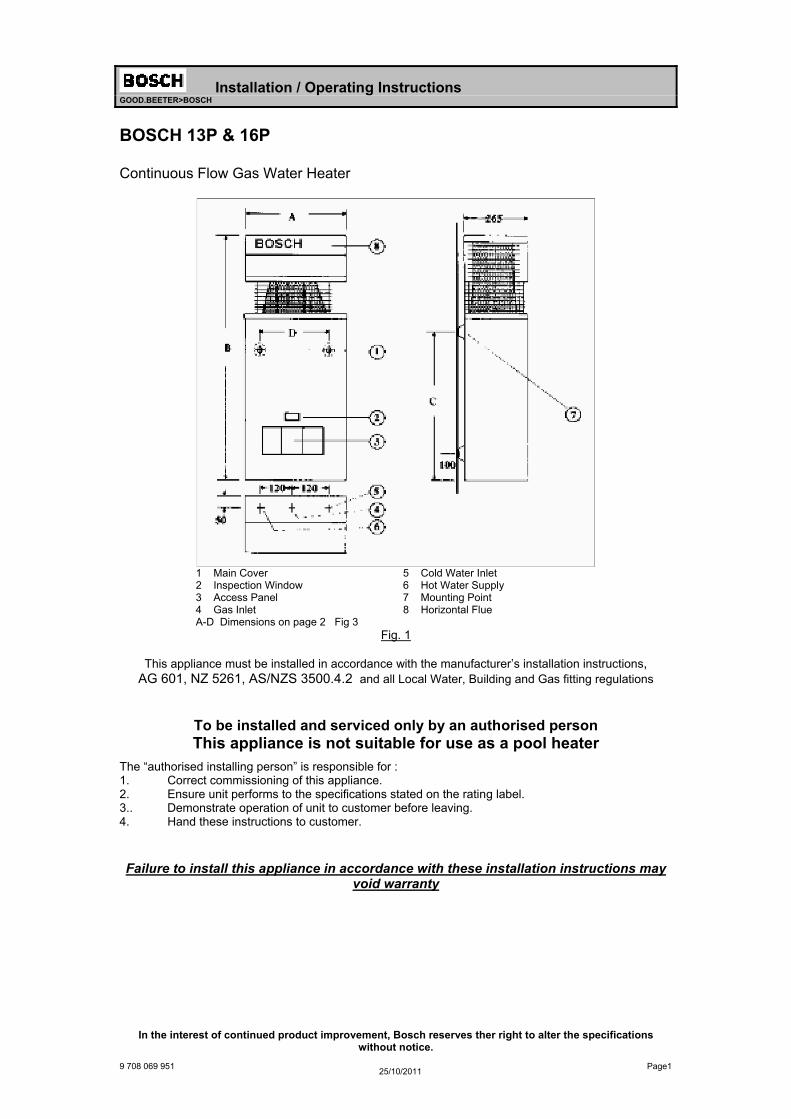
1 Main Cover 5 Cold Water Inlet 2 Inspection Window 6 Hot Water Supply 3 Access Panel 7 Mounting Point 4 Gas Inlet 8 Horizontal Flue A-D Dimensions on page 2 Fig 3
Fig. 1
This appliance must be installed in accordance with the manufacturer’s installation instructions, AG 601, NZ 5261, AS/NZS 3500.4.2 and all Local Water, Building and Gas fitting regulations
To be installed and serviced only by an authorised person This appliance is not suitable for use as a pool heater
The “authorised installing person” is responsible for : 1. Correct commissioning of this appliance. 2. Ensure unit performs to the specifications stated on the rating label. 3.. Demonstrate operation of unit to customer before leaving. 4. Hand these instructions to customer.
Failure to install this appliance in accordance with these installation instructions may void warranty
In the interest of continued product improvement, Bosch reserves ther right to alter the specifications without notice.
25/10/2011
Installation
Install only on an external wall, as close as possible to the most frequently used hot tap. Use a heat shield (accessory item part number 9 708 061 400) if the unit is to be installed on a combustible surface. Allow minimum air gap of 10 mm between the flue and the heat shield, (refer figure 2).
Ensure that the flue terminal is clear of any combustible material, and avoid installation in a marine environment.
Install the appliance such that the base of the appliance is not more than 1.3 metres and not less than 0.5 meters from the ground, and allow for easy access to service heater.
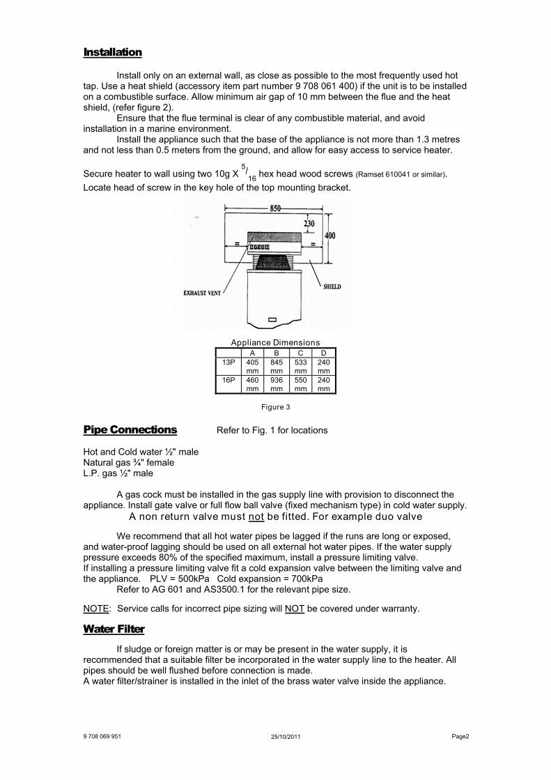
Secure heater to wall using two 10g X 5/
16hex head wood screws (Ramset 610041 or similar).
Locate head of screw in the key hole of the top mounting bracket.
Appliance DimensionsA B C D
13P 405 mm
845 mm
533 mm
240 mm
16P 460 mm
936 mm
550 mm
240 mm
Figure 3
Pipe Connections Refer to Fig. 1 for locations
Hot and Cold water ½" male Natural gas ¾" female L.P. gas ½" male
A gas cock must be installed in the gas supply line with provision to disconnect the appliance. Install gate valve or full flow ball valve (fixed mechanism type) in cold water supply.
A non return valve must not be fitted. For example duo valve
We recommend that all hot water pipes be lagged if the runs are long or exposed, and water-proof lagging should be used on all external hot water pipes. If the water supply pressure exceeds 80% of the specified maximum, install a pressure limiting valve. If installing a pressure limiting valve fit a cold expansion valve between the limiting valve and the appliance. PLV = 500kPa Cold expansion = 700kPa
Refer to AG 601 and AS3500.1 for the relevant pipe size.
NOTE: Service calls for incorrect pipe sizing will NOT be covered under warranty.
Water Filter
If sludge or foreign matter is or may be present in the water supply, it is recommended that a suitable filter be incorporated in the water supply line to the heater. All pipes should be well flushed before connection is made. A water filter/strainer is installed in the inlet of the brass water valve inside the appliance.
Page225/10/20119 708 069 951
9 708 069 951 Page3
Characteristic Data
Bosch 13P Bosch 16P Pilot orifice diameter mm NG 0.30 0.30
LP 0.19 0.19 TG & TLP 0.56 N/A
Burner Injector Diameter mm NG 1.25 1.30 LP 0.79 0.75
TG & TLP 2.25 N/A Minimum water pressure for maximum water flow 100 kPa 150 kPa Maximum water flow litres per minute @ 25°C rise 13 16 Nominal hourly gas consumption Mj/h 100 130 Burner Pressure kPa NG 0.87 0.71
LPG 2.60 2.60
Refer to rating label located on the bottom right hand corner of the back panel for additional data.
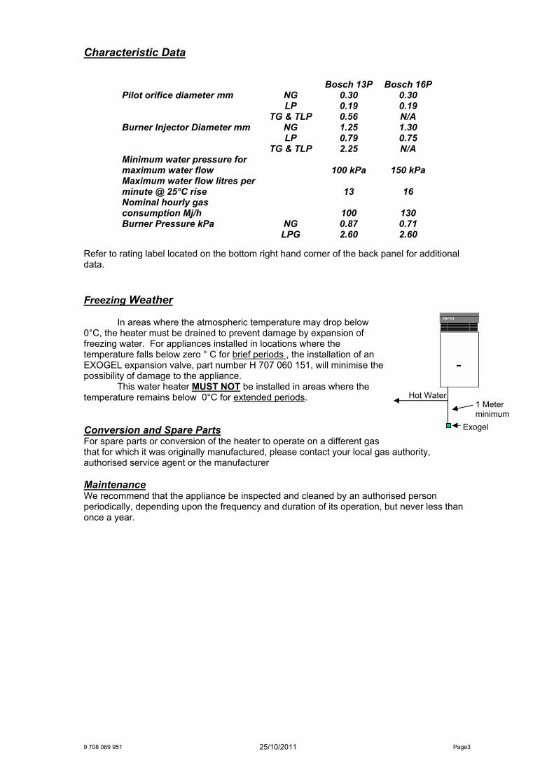
Freezing Weather
In areas where the atmospheric temperature may drop below 0°C, the heater must be drained to prevent damage by expansion of freezing water. For appliances installed in locations where the temperature falls below zero ° C for brief periods , the installation of an EXOGEL expansion valve, part number H 707 060 151, will minimise the possibility of damage to the appliance.
This water heater MUST NOT be installed in areas where the temperature remains below 0°C for extended periods.
Conversion and Spare PartsFor spare parts or conversion of the heater to operate on a different gas that for which it was originally manufactured, please contact your local gas authority, authorised service agent or the manufacturer
MaintenanceWe recommend that the appliance be inspected and cleaned by an authorised person periodically, depending upon the frequency and duration of its operation, but never less than once a year.
Exogel
Hot Water 1 Meter minimum
25/10/2011
Page4
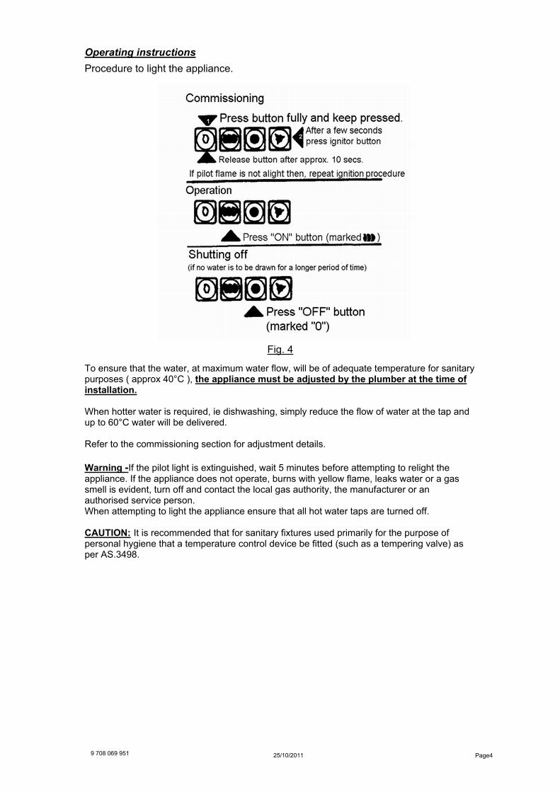
Operating instructions
Procedure to light the appliance.
Fig. 4
To ensure that the water, at maximum water flow, will be of adequate temperature for sanitary purposes ( approx 40°C ), the appliance must be adjusted by the plumber at the time of installation.
When hotter water is required, ie dishwashing, simply reduce the flow of water at the tap and up to 60°C water will be delivered.
Refer to the commissioning section for adjustment details.
Warning -If the pilot light is extinguished, wait 5 minutes before attempting to relight the appliance. If the appliance does not operate, burns with yellow flame, leaks water or a gas smell is evident, turn off and contact the local gas authority, the manufacturer or an authorised service person. When attempting to light the appliance ensure that all hot water taps are turned off.
CAUTION: It is recommended that for sanitary fixtures used primarily for the purpose of personal hygiene that a temperature control device be fitted (such as a tempering valve) as per AS.3498.
25/10/20119 708 069 951
9 708 069 951 20 Page5
Commissioning
The two most important points are to set the maximum water flow rate and to ensure the burner pressure is correct.
1. Water Flow
The water flow must be adjusted so that when a hot water tap is opened fully the appliance has enough time to heat the water as it passes through the heat exchanger. Open a hot water tap fully and adjust the water flow rate to the maximum rate.
Bosch 13P 13 litres / minute Bosch 16P 16 litres / minute
In cool areas where the cold water temperature drops below 15°C in Winter it will be necessary to set the water flow lower than the maximum rate.
Water Wizard 780 8 to 10 litres / minute Water Wizard 960 10 to 12 litres / minute
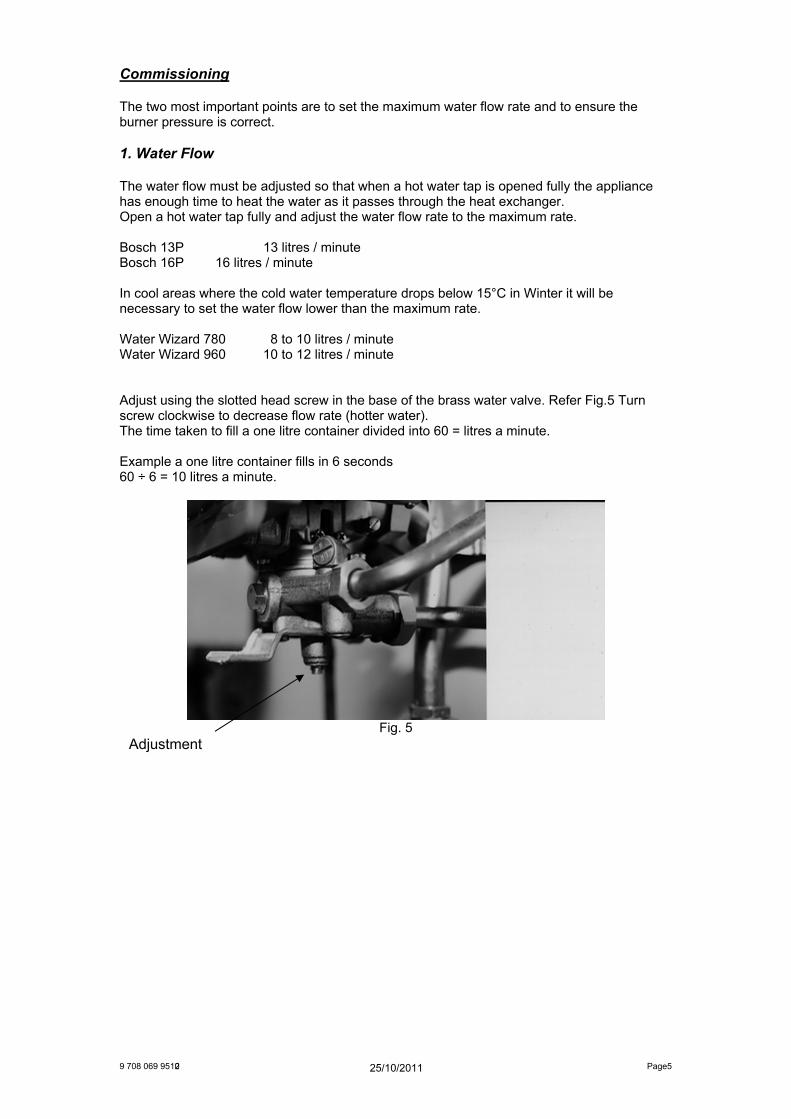
Adjust using the slotted head screw in the base of the brass water valve. Refer Fig.5 Turn screw clockwise to decrease flow rate (hotter water). The time taken to fill a one litre container divided into 60 = litres a minute.
Example a one litre container fills in 6 seconds 60 ÷ 6 = 10 litres a minute.
Fig. 5 Adjustment
25/10/2011
9 708 069 951 2 Page6
Commissioning
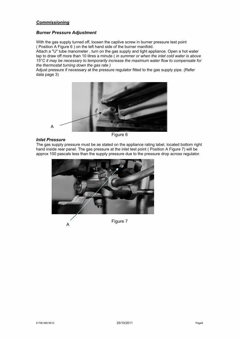
Burner Pressure Adjustment
With the gas supply turned off, loosen the captive screw in burner pressure test point ( Position A Figure 6 ) on the left hand side of the burner manifold. Attach a "U" tube manometer , turn on the gas supply and light appliance. Open a hot water tap to draw off more than 10 litres a minute ( in summer or when the inlet cold water is above 15°C it may be necessary to temporarily increase the maximum water flow to compensate for the thermostat turning down the gas rate )Adjust pressure if necessary at the pressure regulator fitted to the gas supply pipe. (Refer data page 3)
Figure 6 Inlet Pressure The gas supply pressure must be as stated on the appliance rating label, located bottom right hand inside rear panel. The gas pressure at the inlet test point ( Position A Figure 7) will be approx 100 pascals less than the supply pressure due to the pressure drop across regulator.
Figure 7
A
A
25/10/2011
9 708 069 951 Page7
Water Flow d ustment Screw
Thermostat Setting
Method :-
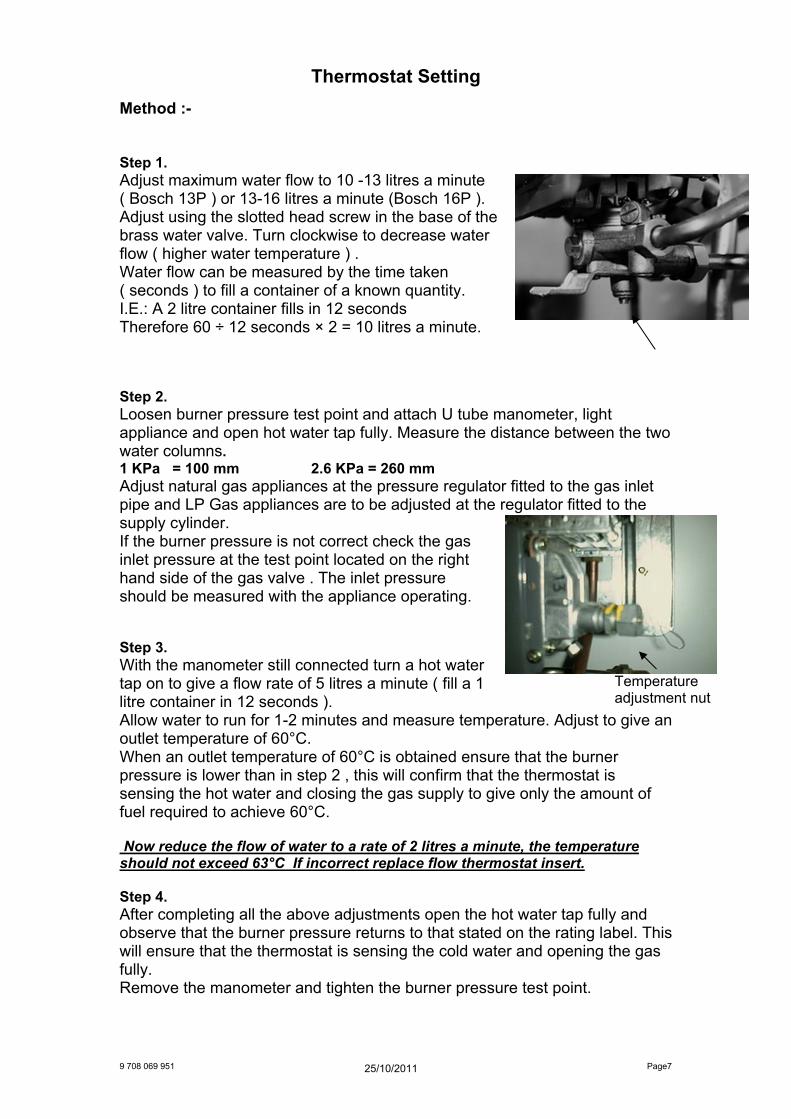
Step 1. Adjust maximum water flow to 10 -13 litres a minute ( Bosch 13P ) or 13-16 litres a minute (Bosch 16P ). Adjust using the slotted head screw in the base of the brass water valve. Turn clockwise to decrease water flow ( higher water temperature ) . Water flow can be measured by the time taken ( seconds ) to fill a container of a known quantity. I.E.: A 2 litre container fills in 12 seconds Therefore 60 ÷ 12 seconds × 2 = 10 litres a minute.
Step 2. Loosen burner pressure test point and attach U tube manometer, light appliance and open hot water tap fully. Measure the distance between the two water columns. 1 KPa = 100 mm 2.6 KPa = 260 mm Adjust natural gas appliances at the pressure regulator fitted to the gas inlet pipe and LP Gas appliances are to be adjusted at the regulator fitted to the supply cylinder. If the burner pressure is not correct check the gas inlet pressure at the test point located on the right hand side of the gas valve . The inlet pressure should be measured with the appliance operating.
Step 3. With the manometer still connected turn a hot water tap on to give a flow rate of 5 litres a minute ( fill a 1 litre container in 12 seconds ). Allow water to run for 1-2 minutes and measure temperature. Adjust to give an outlet temperature of 60°C. When an outlet temperature of 60°C is obtained ensure that the burner pressure is lower than in step 2 , this will confirm that the thermostat is sensing the hot water and closing the gas supply to give only the amount of fuel required to achieve 60°C.
Now reduce the flow of water to a rate of 2 litres a minute, the temperature should not exceed 63°C If incorrect replace flow thermostat insert.
Step 4. After completing all the above adjustments open the hot water tap fully and observe that the burner pressure returns to that stated on the rating label. This will ensure that the thermostat is sensing the cold water and opening the gas fully. Remove the manometer and tighten the burner pressure test point.
Temperature adjustment nut
25/10/2011
9 708 069 951 Page8
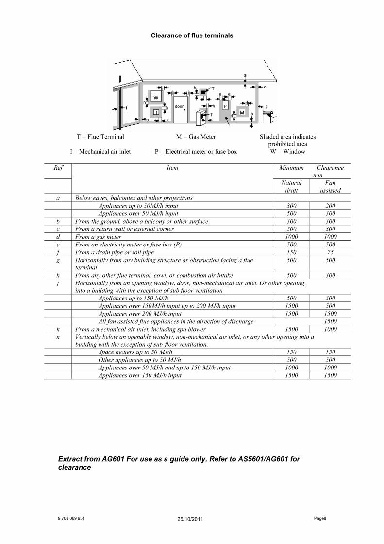
Clearance of flue terminals
T = Flue Terminal M = Gas Meter Shaded area indicates prohibited area
I = Mechanical air inlet P = Electrical meter or fuse box W = Window
Ref Item Minimum Clearance mm
Natural draft
Fan assisted
a Below eaves, balconies and other projections Appliances up to 50MJ/h input 300 200 Appliances over 50 MJ/h input 500 300
b From the ground, above a balcony or other surface 300 300 c From a return wall or external corner 500 300 d From a gas meter 1000 1000 e From an electricity meter or fuse box (P) 500 500 f From a drain pipe or soil pipe 150 75 g Horizontally from any building structure or obstruction facing a flue
terminal 500 500
h From any other flue terminal, cowl, or combustion air intake 500 300 j Horizontally from an opening window, door, non-mechanical air inlet. Or other opening
into a building with the exception of sub floor ventilation Appliances up to 150 MJ/h 500 300 Appliances over 150MJ/h input up to 200 MJ/h input 1500 500 Appliances over 200 MJ/h input 1500 1500 All fan assisted flue appliances in the direction of discharge 1500
k From a mechanical air inlet, including spa blower 1500 1000 n Vertically below an openable window, non-mechanical air inlet, or any other opening into a
building with the exception of sub-floor ventilation: Space heaters up to 50 MJ/h 150 150 Other appliances up to 50 MJ/h 500 500 Appliances over 50 MJ/h and up to 150 MJ/h input 1000 1000 Appliances over 150 MJ/h input 1500 1500
Extract from AG601 For use as a guide only. Refer to AS5601/AG601 for clearance
25/10/2011
Water quality
All Bosch water heating appliances are constructed from high quality materials and components and all are certified for compliance with relevant parts of Australian and New Zealand gas, electrical and water standards.
Whilst Bosch water heaters are warranted against defects, the warranty is conditional upon correct installation and use, in accordance with detailed instructions provided with the heater, in the case of the water supplied to the heater, it is important that the water quality be of acceptable standard.
The water quality limits/parameters listed in water quality table are considered acceptable and generally, Australian and New Zealand suburban water supplies fall within these limits/parameters.
In areas of Australia and New Zealand where water may be supplied, either fully or partly, from bores, artesian wells or similar, one or more of the important limits may well be exceeded and the heater could, therefore, be at risk of failure.
Where uncertainty exists concerning water quality, intending appliance users should seek a water analysis from the water supplying authority and in cases where it is established that the water supply does not meet the quality requirements of the water quality table, the Bosch warranty would not apply.
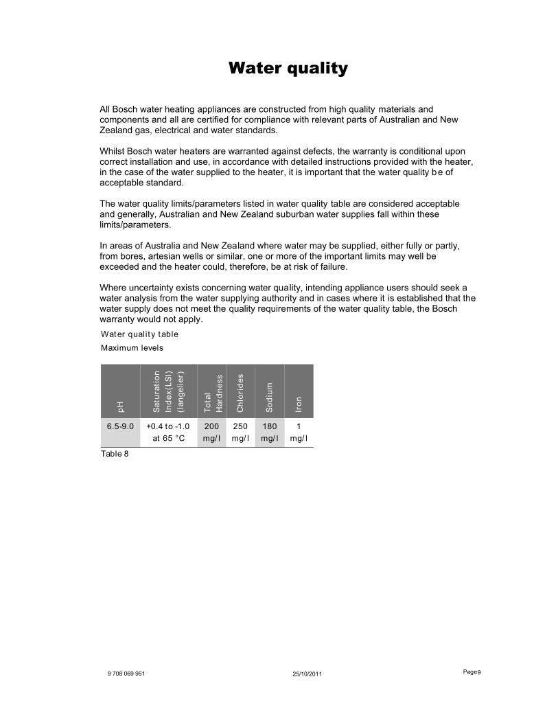
Water qualit y table
Maximum levels
pH
Sa
tura
tio
n
Ind
ex
(LS
I)
(la
ng
eli
er)
To
tal
Ha
rdn
ess
Ch
lori
de
s
So
diu
m
Iro
n
6.5-9.0 +0.4 to -1.0
at 65 °C
200
mg/ l
250
mg/ l
180
mg/ l
1
mg/ l
Table 8
25/10/20119 708 069 951 Page 9
6 720 608 992 (2011/ 12)
9 708 069 951 31/10/20 Page 10
Warranty details Robert Bosch (Australia) Pty Ltd (Bosch) Manufacturer's Warranty (Applicable for purchases from 1 January 2012) All Bosch hot water units are carefully checked, tested and subject to stringent quality controls. 1. Warranty Bosch offers, at its option, to repair or exchange this Bosch hot water unit or the relevant part listed in clause 2 below at no charge, if it becomes faulty or defective in manufacture or materials during the warranty period also stated in clause 2. This warranty is offered in addition to any other rights or remedies held by a consumer at law. 2. Warranty periods & coverage (a) Domestic applications: 2 years (parts and labour) (b) Heat exchangers used in domestic applications: 10 years (parts only) (c) Commercial applications: 12 months (parts and labour) (d) Heat exchangers used in Commercial applications 12 months (parts only) All warranty periods commence on the date of purchase of the hot water unit by the end-user. However, where the date of purchase by the end-user is more than 24 months after the date of manufacture, all warranty periods will automatically commence 24 months after the date of manufacture. 3. Warranty exclusions This warranty is VOID if any damage to or failure of the hot water unit is caused wholly or partly by: (a) Faulty installation (b) Neglect, misuse, accidental or non-accidental damage, failure to follow instructions (c) Use of the unit for purposes other than which it was designed or approved (d) Unauthorised repairs or alterations to the unit without Bosch's consent (e) Use of unauthorised parts and accessories without Bosch's consent (f) Use of non-potable water or bore water in the hot water unit (see product instructions for further details) (g) Continued use after a fault becomes known or apparent. This warranty DOES NOT include: (a) Costs of consumables or accessories (b) Wear and tear, normal or scheduled maintenance (c) To the extent permitted by law, any damage to property, personal injury, direct or indirect loss, consequential losses or other expenses (d) Changes in the condition or operational qualities of the hot water unit due to incorrect storage or mounting or due to climatic, environmental or other influences. NOTE: Any service call costs incurred by the owner or user of the hot water unit for any matter not covered by the terms of this warranty will not be reimbursed by Bosch, even if those costs are incurred during the warranty period. If the hot water unit is located outside the usual operating area of a Bosch service agent, the agent's travel, freight or similar costs are not covered by this warranty and must be paid by the owner or user of the hot water unit. 4. Warranty conditions (a) Proof of purchase may be required. (b) The hot water unit must be installed by an authorised and licensed installer. (c) Proof may be required of the date of installation and correct commissioning of the hot water unit has
6 720 608 992 (2011/ 12)
9 708 069 951 Page 1125/10/2011
been carried out to Bosch's satisfaction (such as a certificate of compliance). (d) Repair or replacement of the hot water unit or any parts under this warranty does not lengthen or renew the warranty period. (e) This warranty is not transferable and is only offered to the original purchaser of the hot water unit. (f) No employee or agent of Bosch is authorised to amend the terms of this warranty. (g) This warranty only applies to Bosch hot water units purchased from an authorised reseller and installed in Australia or New Zealand. (h) To the extent that any condition or warranty implied by law is excludable, such condition or warranty is excluded. 5. How to lodge a warranty claim and warranty procedure (a) Warranty claims must be made with the Bosch Customer Contact Centre (Australia: ph 1300 307 037; New Zealand: ph 0800 543 352). Please be ready to provide the model and serial numbers, date of installation, purchase details and a full description of the problem. Warranty claims must be made before the end of the warranty period. (b) All warranty service calls must conducted by an authorised Bosch service agent. (c) Invoices for attendance and repair of a hot water unit by third parties not authorised by Bosch will not be accepted for payment by Bosch. 6. Privacy Act 1988 (Cth) A customer's personal information collected during warranty claims may be used for the provision of customer support, for t he provision of information about products and services and for other marketing activities undertaken by Bosch and its Bosch Service Agents who are authorised to carry out warranty repairs on behalf of Bosch (Purpose). Bosch is committed to protecting the privacy of its customers' personal information. It will act in compliance with the National Privacy Principles and Privacy Act 1988 (Cth). Bosch will not forward customers' personal information to third parties other than for the Purpose. A customer can object at any time to the use of their personal information for the purpose. Bosch will cease to use a customer's personal information accordingly if an objection is made.
7. Bosch contact details If you have any questions about this warranty or to lodge a warranty claim, please contact: Robert Bosch (Australia) Pty Ltd 1555 Centre Road, Clayton, Victoria 3168 Tel: Australia: 1300 307 037 Tel: New Zealand: 0800 543 352 IMPORTANT NOTE FOR AUSTRALIAN CONSUMERS Our goods come with guarantees that cannot be excluded under the Australian Consumer Law. You are entitled to a replacement or refund for a major failure and for compensation for any other reasonably foreseeable loss or damage. You are also entitled to have the goods repaired or replaced if the goods fail to be of acceptable quality and the failure does not amount to a major failure.