Embed Size (px)
Citation preview
Template 56377 10-05-12 56582/56583/565984_97_A 02-05-141
Manufactured under one or more of these patents. U.S. Patents: 5332944, 5361215, 5550753, 5559720, 5,883,459, 6253227, 6282370, 6590188, 6976052, 6965815, 7030343, 7,417,834 b2, Canadian Patent: 2342614, Australian patent: 2373248 other patents both foreign and domestic applied for and pending. © Copyright 2014 Balboa Water Group.
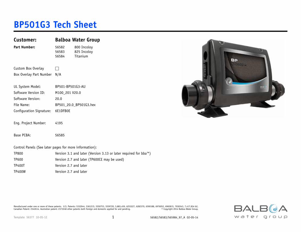
BP501G3 Tech SheetCustomer: Balboa Water GroupPart Number: 56582 800 Incoloy 56583 825 Incoloy 56584 Titanium
Custom Box Overlay □
Box Overlay Part Number N/A
UL System Model: BP501-BP501G3-AU
Software Version ID: M100_201 V20.0
Software Version: 20.0
File Name: BP501_20.0_BP501G3.hex
Configuration Signature: 6E1DFB0E
Eng. Project Number: 4195
Base PCBA: 56585
Control Panels (See later pages for more information):
TP800 Version 3.1 and later (Version 3.13 or later required for bba™)
TP600 Version 2.7 and later (TP600CE may be used)
TP400T Version 2.7 and later
TP400W Version 2.7 and later
Template 56377 10-05-12 56582/56583/565984_97_A 02-05-142
Manufactured under one or more of these patents. U.S. Patents: 5332944, 5361215, 5550753, 5559720, 5,883,459, 6253227, 6282370, 6590188, 6976052, 6965815, 7030343, 7,417,834 b2, Canadian Patent: 2342614, Australian patent: 2373248 other patents both foreign and domestic applied for and pending. © Copyright 2014 Balboa Water Group.
Part # EPN Date Originator Changes Made56582 56583 56584
4195 01-15-14 BWG BP501G3 initial draft. Adds GFCI Trip (but not GFCI Automatic Test). Updated to latest software version, adding topside-inter-grated bba™ support.
System Revision History
bba™ (Balboa Bluetooth Amp) connection is documented seperately.
bba™ is only integrated into graphic display panels (TP800, TP900 and spaTouch™). With TP600 the Aux button operation of bba™ must be used.
Template 56377 10-05-12 56582/56583/565984_97_A 02-05-143
Manufactured under one or more of these patents. U.S. Patents: 5332944, 5361215, 5550753, 5559720, 5,883,459, 6253227, 6282370, 6590188, 6976052, 6965815, 7030343, 7,417,834 b2, Canadian Patent: 2342614, Australian patent: 2373248 other patents both foreign and domestic applied for and pending. © Copyright 2014 Balboa Water Group.
Power Requirements:240VAC, 50/60Hz*, 48A, Class A GFCI-protected service (Circuit Breaker = 60A max.), 4 wires [hot, hot, neutral, ground]
120/240VAC, 50/60Hz*, 16/40A, Class A GFCI-protected service (Circuit Breaker = 20 /50A max.) - Setup 8 ONLY, 3 or 4 wires [hot, hot (optional), neutral, ground].
*BP systems automatically detect 50Hz vs 60Hz.
System Ouputs:Pump 1 240VAC* 2-Speed 10A max 15-minute timer
This is the heater pump Must deliver 20 GPM through heater
Pump 2 240VAC 2-Speed 10A max 15-minute timer
1-Speed in Setups 3, 4, & 7 Unused in Setups 6 & 8
Pump 3 240VAC 1-Speed 10A max 15-minute timer
Used in Setups 1 & 3 only
Blower 240VAC 1-Speed 4A max 15-minute timer Used in Setups 2, 4, & 6
Ozone 240VAC* .5A max Slaved to Pump 1 low
Spa Light 10VAC On/Off 1A max 240-minute timer.
A/V (Stereo) 120VAC Hot 4A max Always on
Heater 5.5kW @ 240VAC max
*Pump 1 and Ozone must be the same voltage.
With 120VAC power input (for Setup 8 only), Pump 1 and Ozone must be set to 120VAC by moving wires attached to J50 and J51 to area 1 (Neutral).
Basic Functions Setup 1 - 8
Template 56377 10-05-12 56582/56583/565984_97_A 02-05-144
Manufactured under one or more of these patents. U.S. Patents: 5332944, 5361215, 5550753, 5559720, 5,883,459, 6253227, 6282370, 6590188, 6976052, 6965815, 7030343, 7,417,834 b2, Canadian Patent: 2342614, Australian patent: 2373248 other patents both foreign and domestic applied for and pending. © Copyright 2014 Balboa Water Group.
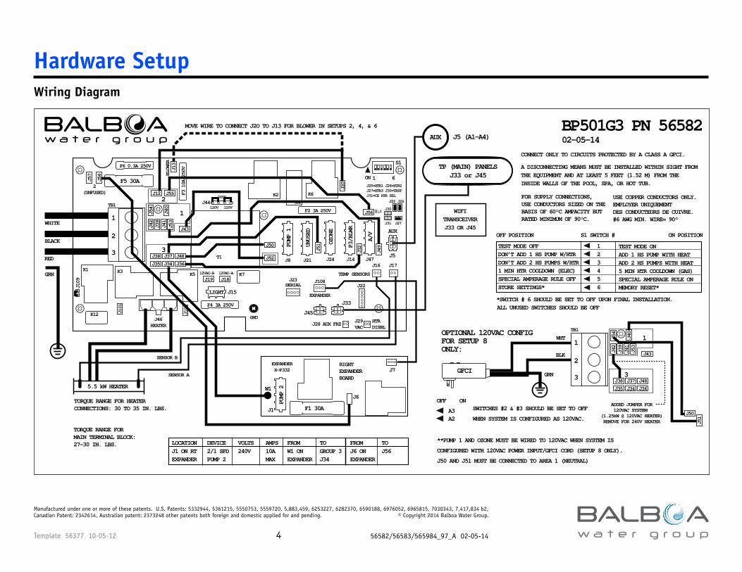
Wiring Diagram
Hardware Setup
F3 1
0A 2
50V
F2 3A 250V
F6 0.3A 250V
J101
J100
J42
J39
J54
J56
J57
J40
J49
J32
J51
J51
J41
J53
J12
J38 J37 J48
J50
J50
J56
J52
J19 J18
J35 J34 J36
J55
J43
J24 J14
F5 30A
K3
TB1
K5
K6K2
K1
K4
OZON
E
J47
A/V
J8 J21
PUMP
1
UNUS
ED
33
2
2(UNFUSED)
2
11
S1
F4 3A 250V
K12
K7
J15
J33
J45
J109
J22
TEMP SENSORS
J16 J17
J28 AUX FRZ
BLOW
ER
J5
AUX
LIGHT
ON 1 6
GNDJ46HEATER
120V 120V
240V
12VAC-B 12VAC-A
J44
J13
J20
P3/B
LWR
J23SERIAL
J108
EXPANDER
J25
J31
J26
J30
J25=HTR1 J26=HTR2J27=HTR3 J30=TESTJ31=CE HTR SEL
J27
T1
02-05-14
TORQUE RANGE FOR HEATER CONNECTIONS: 30 TO 35 IN. LBS.
FOR SUPPLY CONNECTIONS, USE CONDUCTORS SIZED ON THE BASIS OF 60°C AMPACITY BUT RATED MINIMUM OF 90°C.
TORQUE RANGE FOR MAIN TERMINAL BLOCK: 27-30 IN. LBS.
A DISCONNECTING MEANS MUST BE INSTALLED WITHIN SIGHT FROM THE EQUIPMENT AND AT LEAST 5 FEET (1.52 M) FROM THE INSIDE WALLS OF THE POOL, SPA, OR HOT TUB.
CONNECT ONLY TO CIRCUITS PROTECTED BY A CLASS A GFCI.
USE COPPER CONDUCTORS ONLY.EMPLOYER UNIQUEMENT DES CONDUCTEURS DE CUIVRE. #6 AWG MIN. WIRE= 90°
BP501G3 PN 56582
HTRDISBL
J29VAC
PUMP
2
J1
W1
J7RIGHT EXPANDERBOARD
J6
EXPANDERX-P332
F1 30A
LOCATION DEVICE VOLTS AMPS FROM TO FROM TOJ1 ON RT 2/1 SPD 240V 10A W1 ON GROUP 3 J6 ON J56EXPANDER PUMP 2 MAX EXPANDER J34 EXPANDER
MOVE WIRE TO CONNECT J2O TO J13 FOR BLOWER IN SETUPS 2, 4, & 6
ALL UNUSED SWITCHES SHOULD BE OFF
TEST MODE OFFDON’T ADD 1 HS PUMP W/HTRDON’T ADD 2 HS PUMPS W/HTR1 MIN HTR COOLDOWN (ELEC)SPECIAL AMPERAGE RULE OFFSTORE SETTINGS*
TEST MODE ON ADD 1 HS PUMP WITH HEATADD 2 HS PUMPS WITH HEAT5 MIN HTR COOLDOWN (GAS)SPECIAL AMPERAGE RULE ONMEMORY RESET*
123456
ON POSITION S1 SWITCH #OFF POSITION
*SWITCH # 6 SHOULD BE SET TO OFF UPON FINAL INSTALLATION.
5.5 kW HEATER
SENSOR A
SENSOR B
TP (MAIN) PANELSJ33 or J45
AUX J5 (A1-A4)
WIFITRANSCEIVERJ33 OR J45
WHITE
BLACK
RED
GRN
OPTIONAL 120VAC CONFIG FOR SETUP 8 ONLY:
GRN
BLK
WHT
GFCI
J42
J39
J54
J40
J41
J53
J38 J37 J48J35 J34 J36
J43
TB1
33
2
11
A3A2
SWITCHES #2 & #3 SHOULD BE SET TO OFF
WHEN SYSTEM IS CONFIGURED AS 120VAC.
**PUMP 1 AND OZONE MUST BE WIRED TO 120VAC WHEN SYSTEM IS
CONFIGURED WITH 120VAC POWER INPUT/GFCI CORD (SETUP 8 ONLY).
J50 AND J51 MUST BE CONNECTED TO AREA 1 (NEUTRAL)
ONOFFADDED JUMPER FOR120VAC SYSTEM
(1.25kW @ 120VAC HEATER)REMOVE FOR 240V HEATER
Template 56377 10-05-12 56582/56583/565984_97_A 02-05-145
Manufactured under one or more of these patents. U.S. Patents: 5332944, 5361215, 5550753, 5559720, 5,883,459, 6253227, 6282370, 6590188, 6976052, 6965815, 7030343, 7,417,834 b2, Canadian Patent: 2342614, Australian patent: 2373248 other patents both foreign and domestic applied for and pending. © Copyright 2014 Balboa Water Group.
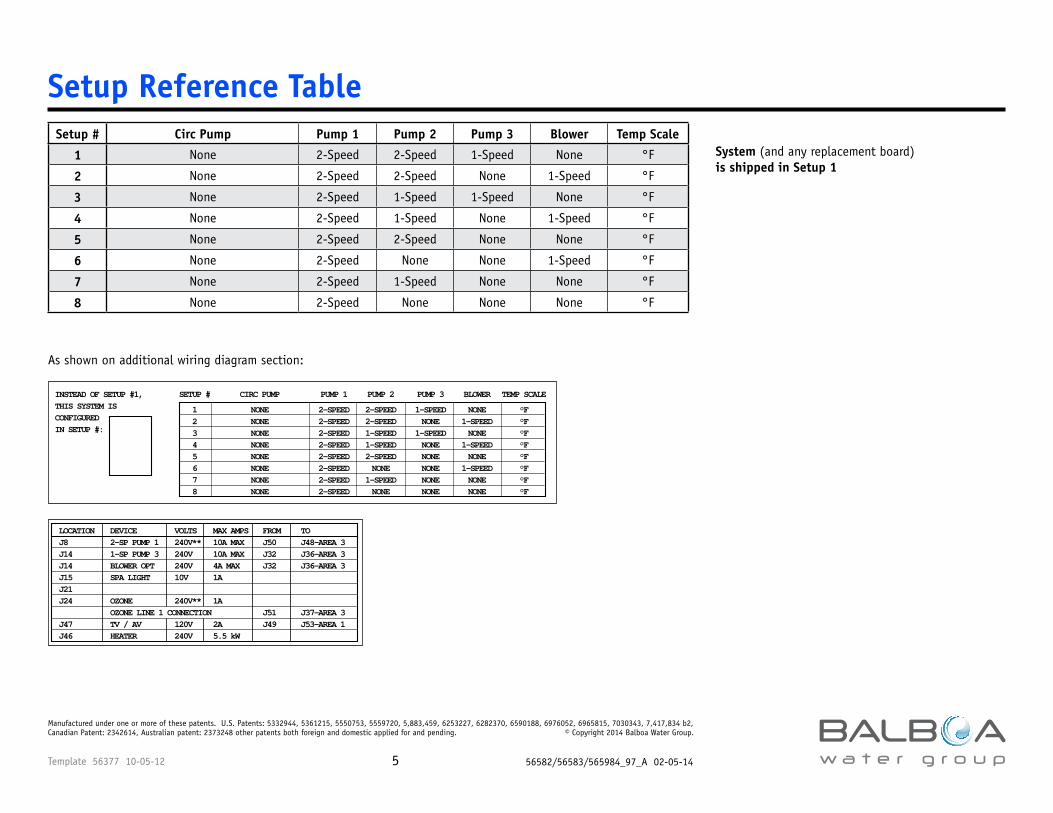
Setup # Circ Pump Pump 1 Pump 2 Pump 3 Blower Temp Scale
1 None 2-Speed 2-Speed 1-Speed None °F
2 None 2-Speed 2-Speed None 1-Speed °F
3 None 2-Speed 1-Speed 1-Speed None °F
4 None 2-Speed 1-Speed None 1-Speed °F
5 None 2-Speed 2-Speed None None °F
6 None 2-Speed None None 1-Speed °F
7 None 2-Speed 1-Speed None None °F
8 None 2-Speed None None None °F
Setup Reference Table
System (and any replacement board) is shipped in Setup 1
1 NONE 2-SPEED 2-SPEED 1-SPEED NONE °F 2 NONE 2-SPEED 2-SPEED NONE 1-SPEED °F 3 NONE 2-SPEED 1-SPEED 1-SPEED NONE °F 4 NONE 2-SPEED 1-SPEED NONE 1-SPEED °F 5 NONE 2-SPEED 2-SPEED NONE NONE °F 6 NONE 2-SPEED NONE NONE 1-SPEED °F 7 NONE 2-SPEED 1-SPEED NONE NONE °F 8 NONE 2-SPEED NONE NONE NONE °F
SETUP # CIRC PUMP PUMP 1 PUMP 2 PUMP 3 BLOWER TEMP SCALEINSTEAD OF SETUP #1,THIS SYSTEM IS CONFIGURED IN SETUP #:
LOCATION DEVICE VOLTS MAX AMPS FROM TOJ8 2-SP PUMP 1 240V** 10A MAX J50 J48-AREA 3J14 1-SP PUMP 3 240V 10A MAX J32 J36-AREA 3J14 BLOWER OPT 240V 4A MAX J32 J36-AREA 3J15 SPA LIGHT 10V 1A J21 J24 OZONE 240V** 1A OZONE LINE 1 CONNECTION J51 J37-AREA 3 J47 TV / AV 120V 2A J49 J53-AREA 1 J46 HEATER 240V 5.5 kW
As shown on additional wiring diagram section:
Template 56377 10-05-12 56582/56583/565984_97_A 02-05-146
Manufactured under one or more of these patents. U.S. Patents: 5332944, 5361215, 5550753, 5559720, 5,883,459, 6253227, 6282370, 6590188, 6976052, 6965815, 7030343, 7,417,834 b2, Canadian Patent: 2342614, Australian patent: 2373248 other patents both foreign and domestic applied for and pending. © Copyright 2014 Balboa Water Group.
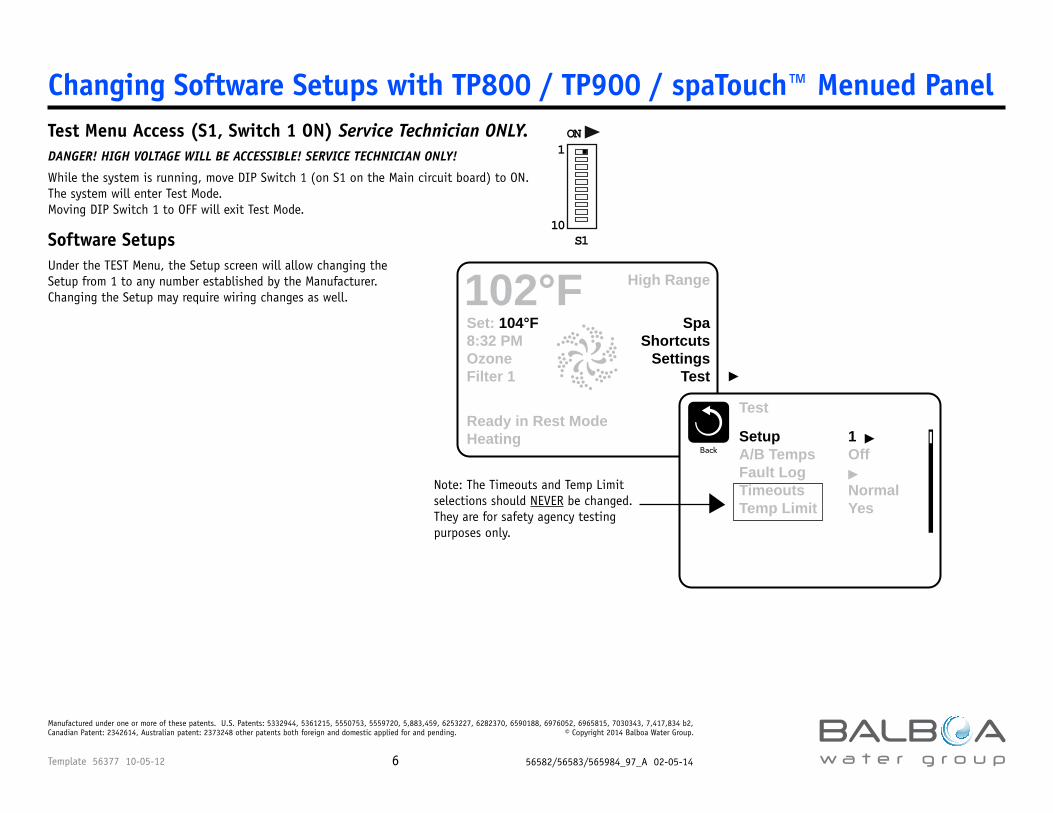
Test Menu Access (S1, Switch 1 ON) Service Technician ONLY.DANGER! HIGH VOLTAGE WILL BE ACCESSIBLE! SERVICE TECHNICIAN ONLY!
While the system is running, move DIP Switch 1 (on S1 on the Main circuit board) to ON. The system will enter Test Mode. Moving DIP Switch 1 to OFF will exit Test Mode.
Software Setups Under the TEST Menu, the Setup screen will allow changing the Setup from 1 to any number established by the Manufacturer. Changing the Setup may require wiring changes as well.
Changing Software Setups with TP800 / TP900 / spaTouch™ Menued Panel
Set: 104°F8:32 PMOzoneFilter 1
SpaShortcuts
SettingsTest
High Range102°F
Ready in Rest ModeHeating
ON1
10S1
Test
BackSetupA/B TempsFault LogTimeoutsTemp Limit
1 Off
NormalYes
Note: The Timeouts and Temp Limit selections should NEVER be changed. They are for safety agency testing purposes only.
Template 56377 10-05-12 56582/56583/565984_97_A 02-05-147
Manufactured under one or more of these patents. U.S. Patents: 5332944, 5361215, 5550753, 5559720, 5,883,459, 6253227, 6282370, 6590188, 6976052, 6965815, 7030343, 7,417,834 b2, Canadian Patent: 2342614, Australian patent: 2373248 other patents both foreign and domestic applied for and pending. © Copyright 2014 Balboa Water Group.
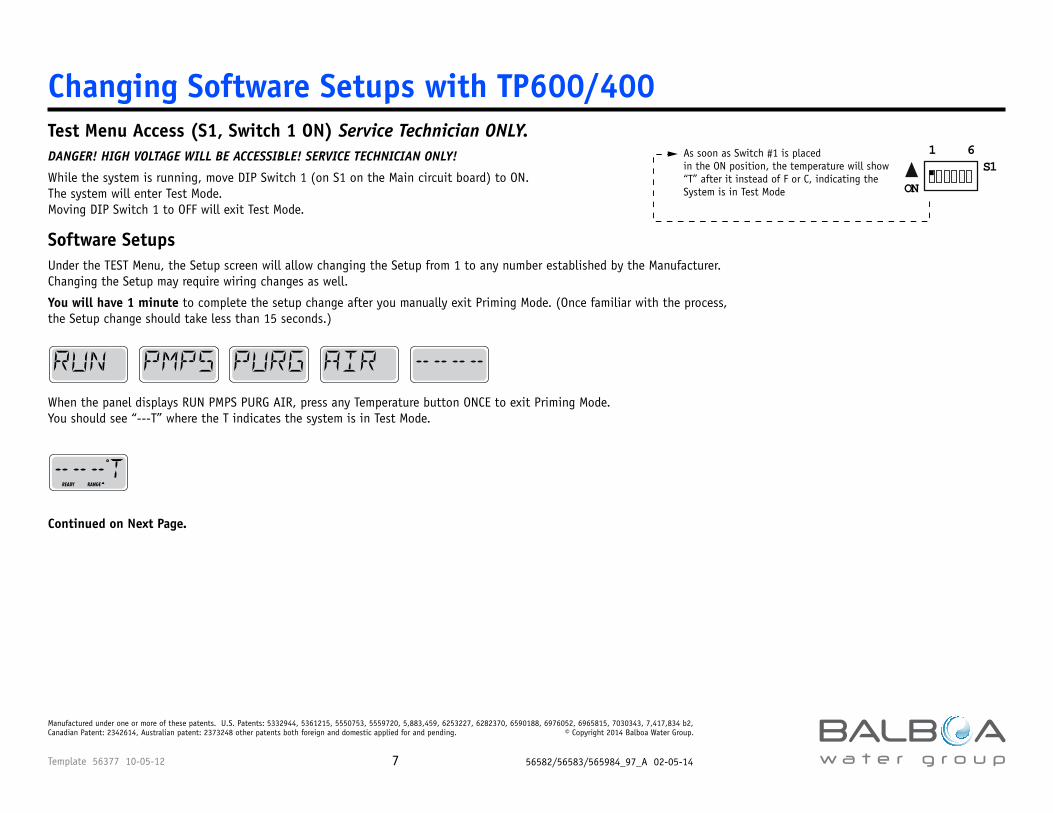
Changing Software Setups with TP600/400Test Menu Access (S1, Switch 1 ON) Service Technician ONLY.DANGER! HIGH VOLTAGE WILL BE ACCESSIBLE! SERVICE TECHNICIAN ONLY!
While the system is running, move DIP Switch 1 (on S1 on the Main circuit board) to ON. The system will enter Test Mode. Moving DIP Switch 1 to OFF will exit Test Mode.
Software Setups Under the TEST Menu, the Setup screen will allow changing the Setup from 1 to any number established by the Manufacturer. Changing the Setup may require wiring changes as well.
You will have 1 minute to complete the setup change after you manually exit Priming Mode. (Once familiar with the process, the Setup change should take less than 15 seconds.)
ON
1 6S1
As soon as Switch #1 is placed in the ON position, the temperature will show“T” after it instead of F or C, indicating the System is in Test Mode
When the panel displays RUN PMPS PURG AIR, press any Temperature button ONCE to exit Priming Mode. You should see “---T” where the T indicates the system is in Test Mode.
Continued on Next Page.
READY RANGE
Template 56377 10-05-12 56582/56583/565984_97_A 02-05-148
Manufactured under one or more of these patents. U.S. Patents: 5332944, 5361215, 5550753, 5559720, 5,883,459, 6253227, 6282370, 6590188, 6976052, 6965815, 7030343, 7,417,834 b2, Canadian Patent: 2342614, Australian patent: 2373248 other patents both foreign and domestic applied for and pending. © Copyright 2014 Balboa Water Group.
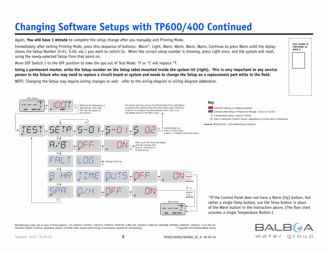
Changing Software Setups with TP600/400 ContinuedAgain, You will have 1 minute to complete the setup change after you manually exit Priming Mode.
Immediately after exiting Priming Mode, press this sequence of buttons: Warm*, Light, Warm, Warm, Warm, Warm. Continue to press Warm until the diplay shows the Setup Number (S-01, S-02, etc.) you want to switch to. When the correct setup number is showing, press Light once, and the system will reset, using the newly-selected Setup from that point on.
Move DIP Switch 1 to the OFF position to take the spa out of Test Mode. °F or °C will replace °T.
Using a permanent marker, write the Setup number on the Setup label mounted inside the system lid (right). This is very important to any service person in the future who may need to replace a circuit board or system and needs to change the Setup on a replacement part while in the field.
NOTE: Changing the Setup may require wiring changes as well - refer to the wiring diagram or wiring diagram addendum.
THIS SYSTEM ISCONFIGURED ASSETUP #
Indicates Flashing or Changing Segment
Key
A temperature button, used for “Action” Light or dedicated “Choose” button, depending on control panel configuration
Indicates Alternating or Progressive Message - every 1/2 second
Waiting time - varies depending on function
SETSET
The System will reset and go into Priming Mode if the Light Button is pressed while anything other than the current setup is flashing. If there is no change to the Setup Number (S-01, S-02, etc.), the display returns to the SETP screen.
Several Setups can exist in in this stringA dash (--) indicates the current Setup.SET
SET SET
SET SET
SET SET
While the Set Temperature is still flashing, press LightTEST will now appear in the LCD first.
SET RANGE
Main Screen
READY RANGE FLTR1
Main Screen
READY RANGE FLTR1
SET
Approx.5 sec.
or
Approx.5 sec.
or
SET
SET
SET
SET
When set to ON, Panel will display alternate readings from Senor A and Sensor B on Main Screen
Displays Fault Log
*If the Control Panel does not have a Warm (Up) button, but rather a single Temp button, use the Temp button in place of the Warm button in the instruction above. (The flow chart assumes a single Temperature Button.)
Template 56377 10-05-12 56582/56583/565984_97_A 02-05-149
Manufactured under one or more of these patents. U.S. Patents: 5332944, 5361215, 5550753, 5559720, 5,883,459, 6253227, 6282370, 6590188, 6976052, 6965815, 7030343, 7,417,834 b2, Canadian Patent: 2342614, Australian patent: 2373248 other patents both foreign and domestic applied for and pending. © Copyright 2014 Balboa Water Group.
Expansion FeaturesControl Connection Default Fuse Relay 1/2 (J108) 2/1-Speed Pump 2 30A
Equipment Expansion
Template 56377 10-05-12 56582/56583/565984_97_A 02-05-1410
Manufactured under one or more of these patents. U.S. Patents: 5332944, 5361215, 5550753, 5559720, 5,883,459, 6253227, 6282370, 6590188, 6976052, 6965815, 7030343, 7,417,834 b2, Canadian Patent: 2342614, Australian patent: 2373248 other patents both foreign and domestic applied for and pending. © Copyright 2014 Balboa Water Group.
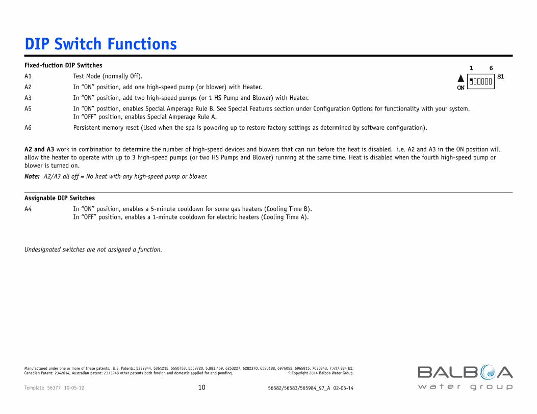
Fixed-fuction DIP Switches
A1 Test Mode (normally Off).
A2 In “ON” position, add one high-speed pump (or blower) with Heater.
A3 In “ON” position, add two high-speed pumps (or 1 HS Pump and Blower) with Heater.
A5 In “ON” position, enables Special Amperage Rule B. See Special Features section under Configuration Options for functionality with your system. In “OFF” position, enables Special Amperage Rule A.
A6 Persistent memory reset (Used when the spa is powering up to restore factory settings as determined by software configuration).
A2 and A3 work in combination to determine the number of high-speed devices and blowers that can run before the heat is disabled. i.e. A2 and A3 in the ON position will allow the heater to operate with up to 3 high-speed pumps (or two HS Pumps and Blower) running at the same time. Heat is disabled when the fourth high-speed pump or blower is turned on.
Note: A2/A3 all off = No heat with any high-speed pump or blower.
Assignable DIP Switches
A4 In “ON” position, enables a 5-minute cooldown for some gas heaters (Cooling Time B). In “OFF” position, enables a 1-minute cooldown for electric heaters (Cooling Time A).
Undesignated switches are not assigned a function.
DIP Switch Functions
ON
1 6S1
Template 56377 10-05-12 56582/56583/565984_97_A 02-05-1411
Manufactured under one or more of these patents. U.S. Patents: 5332944, 5361215, 5550753, 5559720, 5,883,459, 6253227, 6282370, 6590188, 6976052, 6965815, 7030343, 7,417,834 b2, Canadian Patent: 2342614, Australian patent: 2373248 other patents both foreign and domestic applied for and pending. © Copyright 2014 Balboa Water Group.
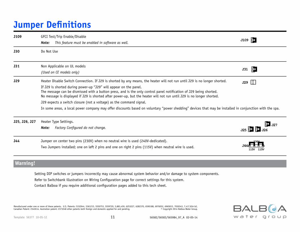
Jumper DefinitionsJ109 GFCI Test/Trip Enable/Disable
Note: This feature must be enabled in software as well.
J30 Do Not Use
J31 Non Applicable on UL models
(Used on CE models only)
J29 Heater Disable Switch Connection. If J29 is shorted by any means, the heater will not run until J29 is no longer shorted.
If J29 is shorted during power-up “J29” will appear on the panel. The message can be dismissed with a button press, and is the only control panel notification of J29 being shorted. No message is displayed if J29 is shorted after power-up, but the heater will not run until J29 is no longer shorted.
J29 expects a switch closure (not a voltage) as the command signal.
In some areas, a local power company may offer discounts based on voluntary “power shedding” devices that may be installed in conjunction with the spa.
J25, J26, J27 Heater Type Settings.
Note: Factory Configured do not change.
J44 Jumper on center two pins (230V) when no neutral wire is used (240V-dedicated).
Two Jumpers installed; one on left 2 pins and one on right 2 pins (115V) when neutral wire is used.
Warning!
Setting DIP switches or jumpers incorrectly may cause abnormal system behavior and/or damage to system components.
Refer to Switchbank illustration on Wiring Configuration page for correct settings for this system.
Contact Balboa if you require additional configuration pages added to this tech sheet.
J109
J25 J26J27
J31
115V 115V
230VJ44
J29
Template 56377 10-05-12 56582/56583/565984_97_A 02-05-1412
Manufactured under one or more of these patents. U.S. Patents: 5332944, 5361215, 5550753, 5559720, 5,883,459, 6253227, 6282370, 6590188, 6976052, 6965815, 7030343, 7,417,834 b2, Canadian Patent: 2342614, Australian patent: 2373248 other patents both foreign and domestic applied for and pending. © Copyright 2014 Balboa Water Group.
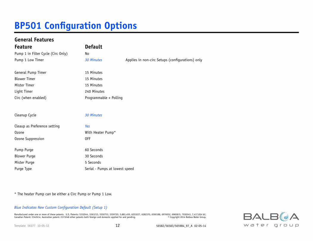
BP501 Configuration OptionsGeneral FeaturesFeature Default Pump 1 in Filter Cycle (Circ Only) No
Pump 1 Low Timer 30 Minutes Applies in non-circ Setups (configurations) only
General Pump Timer 15 Minutes
Blower Timer 15 Minutes
Mister Timer 15 Minutes
Light Timer 240 Minutes
Circ (when enabled) Programmable + Polling
Circ Pump can be set with the following functions: 24 hr – 24 hr w/3° shutoff – Acts like P1 Low (filters, polls, etc. - Requires a single-speed P1)
Cleanup Cycle 30 Minutes Between 30 and 240 minutes 30 Minutes - or OFF
Cleaup as Preference setting Yes Yes, No N/A
Ozone With Heater Pump* Always, Filters/Cleanup Only N/A
Ozone Suppression OFF Between 30 and 120 min. 1 Minute - or OFF
Pump Purge 60 Seconds Between 30 and 600 seconds 5 Seconds
Blower Purge 30 Seconds Between 5 and 300 seconds 5 Seconds
Mister Purge 5 Seconds
Purge Type Serial - Pumps at lowest speed
Blue Indicates New Custom Configuration Default (Setup 1)
* The heater Pump can be either a Circ Pump or Pump 1 Low.
Template 56377 10-05-12 56582/56583/565984_97_A 02-05-1413
Manufactured under one or more of these patents. U.S. Patents: 5332944, 5361215, 5550753, 5559720, 5,883,459, 6253227, 6282370, 6590188, 6976052, 6965815, 7030343, 7,417,834 b2, Canadian Patent: 2342614, Australian patent: 2373248 other patents both foreign and domestic applied for and pending. © Copyright 2014 Balboa Water Group.
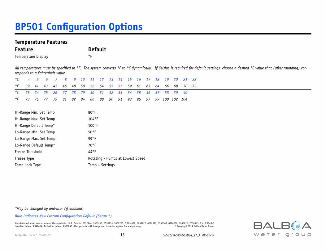
BP501 Configuration OptionsTemperature FeaturesFeature Default Options IncrementTemperature Display °F °C, °F
All temperatures must be specified in °F. The system converts °F to °C dynamically. If Celsius is required for default settings, choose a desired °C value that (after rounding) cor-responds to a Fahrenheit value.
°C 4 5 6 7 8 9 10 11 12 13 14 15 16 17 18 19 20 21 22
°F 39 41 43 45 46 48 50 52 54 55 57 59 61 63 64 66 68 70 72
°C 23 24 25 26 27 28 29 30 31 32 33 34 35 36 37 38 39 40
°F 73 75 77 79 81 82 84 86 88 90 91 93 95 97 99 100 102 104
Hi-Range Min. Set Temp 80°F Between 50 and 80°F 1°F
Hi-Range Max. Set Temp 104°F Between 60 and 104°F 1°F
Hi-Range Default Temp* 100°F Between 50 and 104°F 1°F
Lo-Range Min. Set Temp 50°F Between 50 and 80°F 1°F
Lo-Range Max. Set Temp 99°F Between 60 and 99°F 1°F
Lo-Range Default Temp* 70°F Between 50 and 99°F 1°F
Freeze Threshold 44°F
Freeze Type Rotating - Pumps at Lowest Speed
Temp Lock Type Temp + Settings
*May be changed by end-user (if enabled)
Blue Indicates New Custom Configuration Default (Setup 1)
Template 56377 10-05-12 56582/56583/565984_97_A 02-05-1414
Manufactured under one or more of these patents. U.S. Patents: 5332944, 5361215, 5550753, 5559720, 5,883,459, 6253227, 6282370, 6590188, 6976052, 6965815, 7030343, 7,417,834 b2, Canadian Patent: 2342614, Australian patent: 2373248 other patents both foreign and domestic applied for and pending. © Copyright 2014 Balboa Water Group.
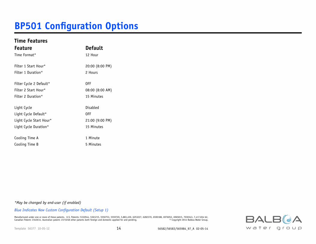
BP501 Configuration OptionsTime FeaturesFeature Default Options IncrementTime Format* 12 Hour 12 Hour, 24 Hour N/A
Filter 1 Start Hour* 20:00 (8:00 PM) 00:00 to 23:00 1 Hour
Filter 1 Duration* 2 Hours Between 15 Min and 23:45 15 Minutes -or continuous
Filter Cycle 2 Default* OFF OFF, ON N/A
Filter 2 Start Hour* 08:00 (8:00 AM) 00:00 to 23:00 1 Hour
Filter 2 Duration* 15 Minutes Between 15 Min and 23:45 15 Minutes -or Continuous, or Disabled
Light Cycle Disabled Disabled, Enabled N/A
Light Cycle Default* OFF OFF, ON N/A
Light Cycle Start Hour* 21:00 (9:00 PM) 00:00 to 23:00 1 Hour
Light Cycle Duration* 15 Minutes Between 15 Min and 04:00 15 Minutes -or or Disabled
Cooling Time A 1 Minute
Cooling Time B 5 Minutes
*May be changed by end-user (if enabled)
Blue Indicates New Custom Configuration Default (Setup 1)
Template 56377 10-05-12 56582/56583/565984_97_A 02-05-1415
Manufactured under one or more of these patents. U.S. Patents: 5332944, 5361215, 5550753, 5559720, 5,883,459, 6253227, 6282370, 6590188, 6976052, 6965815, 7030343, 7,417,834 b2, Canadian Patent: 2342614, Australian patent: 2373248 other patents both foreign and domestic applied for and pending. © Copyright 2014 Balboa Water Group.
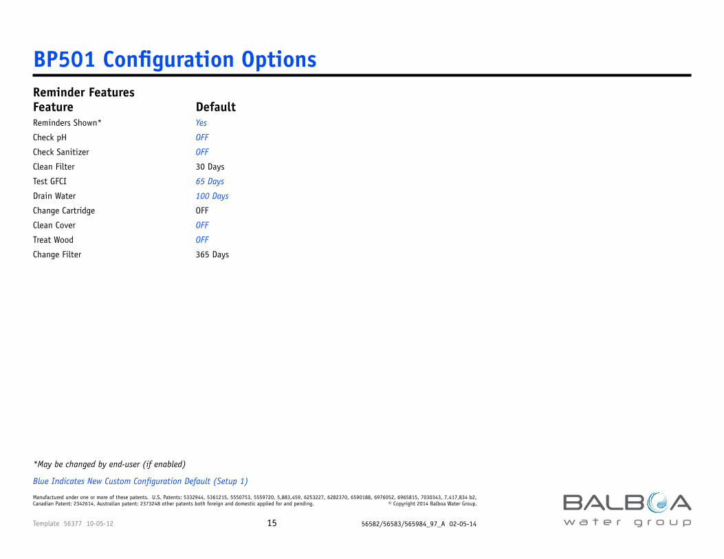
BP501 Configuration OptionsReminder FeaturesFeature Default Options IncrementReminders Shown* Yes Yes, No N/A
Check pH OFF See Reminder Period Note 1 Days
Check Sanitizer OFF See Reminder Period Note 1 Days
Clean Filter 30 Days See Reminder Period Note 1 Days
Test GFCI 65 Days See Reminder Period Note 1 Days
Drain Water 100 Days See Reminder Period Note 1 Days
Change Cartridge OFF See Reminder Period Note 1 Days
Clean Cover OFF See Reminder Period Note 1 Days
Treat Wood OFF See Reminder Period Note 1 Days
Change Filter 365 Days See Reminder Period Note 1 Days
Reminder Periods can be set between 7 and 180 days. In addition, 365 days can be chosen. Each reminder can be turned OFF individually.
*May be changed by end-user (if enabled)
Blue Indicates New Custom Configuration Default (Setup 1)
Template 56377 10-05-12 56582/56583/565984_97_A 02-05-1416
Manufactured under one or more of these patents. U.S. Patents: 5332944, 5361215, 5550753, 5559720, 5,883,459, 6253227, 6282370, 6590188, 6976052, 6965815, 7030343, 7,417,834 b2, Canadian Patent: 2342614, Australian patent: 2373248 other patents both foreign and domestic applied for and pending. © Copyright 2014 Balboa Water Group.
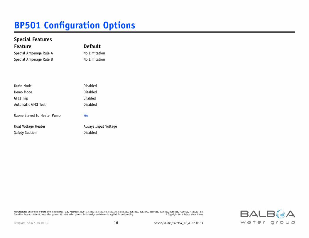
BP501 Configuration OptionsSpecial FeaturesFeature Default Options IncrementSpecial Amperage Rule A No Limitation 1 Pump
Special Amperage Rule B No Limitation 1 Pump
1 to 7 pumps can run on high speed together. Blower can be allowed or suppressed when number of pumps selected is reached. “No Limitation” does not restrict pump or blower operation. DIP Switch 5 is used to choose Special Amperage Rule 1 or 2.
Drain Mode Disabled Disabled, Enabled N/A
Demo Mode Disabled
GFCI Trip Enabled Disabled, Enabled N/A
Automatic GFCI Test Disabled Disabled, 1-7 Days 1 Day When GFCI Test is Enabled, the Auto-Test can be set between 1 and 7 days from startup
Ozone Slaved to Heater Pump Yes Yes, No N/A
Dual Voltage Heater Always Input Voltage 4°F Temperature Delta N/A
Safety Suction Disabled Disabled, Enabled N/A
Template 56377 10-05-12 56582/56583/565984_97_A 02-05-1417
Manufactured under one or more of these patents. U.S. Patents: 5332944, 5361215, 5550753, 5559720, 5,883,459, 6253227, 6282370, 6590188, 6976052, 6965815, 7030343, 7,417,834 b2, Canadian Patent: 2342614, Australian patent: 2373248 other patents both foreign and domestic applied for and pending. © Copyright 2014 Balboa Water Group.
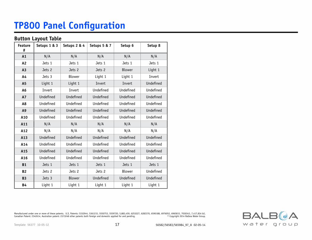
TP800 Panel ConfigurationButton Layout Table
Feature #
Setups 1 & 3 Setups 2 & 4 Setups 5 & 7 Setup 6 Setup 8
A1 N/A N/A N/A N/A N/A
A2 Jets 1 Jets 1 Jets 1 Jets 1 Jets 1
A3 Jets 2 Jets 2 Jets 2 Blower Light 1
A4 Jets 3 Blower Light 1 Light 1 Invert
A5 Light 1 Light 1 Invert Invert Undefined
A6 Invert Invert Undefined Undefined Undefined
A7 Undefined Undefined Undefined Undefined Undefined
A8 Undefined Undefined Undefined Undefined Undefined
A9 Undefined Undefined Undefined Undefined Undefined
A10 Undefined Undefined Undefined Undefined Undefined
A11 N/A N/A N/A N/A N/A
A12 N/A N/A N/A N/A N/A
A13 Undefined Undefined Undefined Undefined Undefined
A14 Undefined Undefined Undefined Undefined Undefined
A15 Undefined Undefined Undefined Undefined Undefined
A16 Undefined Undefined Undefined Undefined Undefined
B1 Jets 1 Jets 1 Jets 1 Jets 1 Jets 1
B2 Jets 2 Jets 2 Jets 2 Blower Undefined
B3 Jets 3 Blower Undefined Undefined Undefined
B4 Light 1 Light 1 Light 1 Light 1 Light 1
Template 56377 10-05-12 56582/56583/565984_97_A 02-05-1418
Manufactured under one or more of these patents. U.S. Patents: 5332944, 5361215, 5550753, 5559720, 5,883,459, 6253227, 6282370, 6590188, 6976052, 6965815, 7030343, 7,417,834 b2, Canadian Patent: 2342614, Australian patent: 2373248 other patents both foreign and domestic applied for and pending. © Copyright 2014 Balboa Water Group.
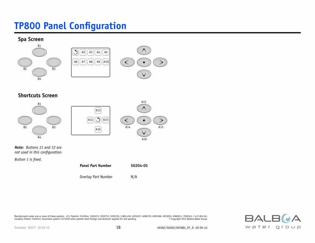
TP800 Panel ConfigurationSpa Screen
Shortcuts Screen
A2 A3 A4 A5
A6 A7 A8 A9 A10
A16
A15A14
A13
B1
B1
B3
B3
B4
B4
B2
B2
A13
A14 A15
A16
Note: Buttons 11 and 12 are not used in this configuration.
Button 1 is fixed.
Panel Part Number 50204-05
Overlay Part Number N/A
Template 56377 10-05-12 56582/56583/565984_97_A 02-05-1419
Manufactured under one or more of these patents. U.S. Patents: 5332944, 5361215, 5550753, 5559720, 5,883,459, 6253227, 6282370, 6590188, 6976052, 6965815, 7030343, 7,417,834 b2, Canadian Patent: 2342614, Australian patent: 2373248 other patents both foreign and domestic applied for and pending. © Copyright 2014 Balboa Water Group.
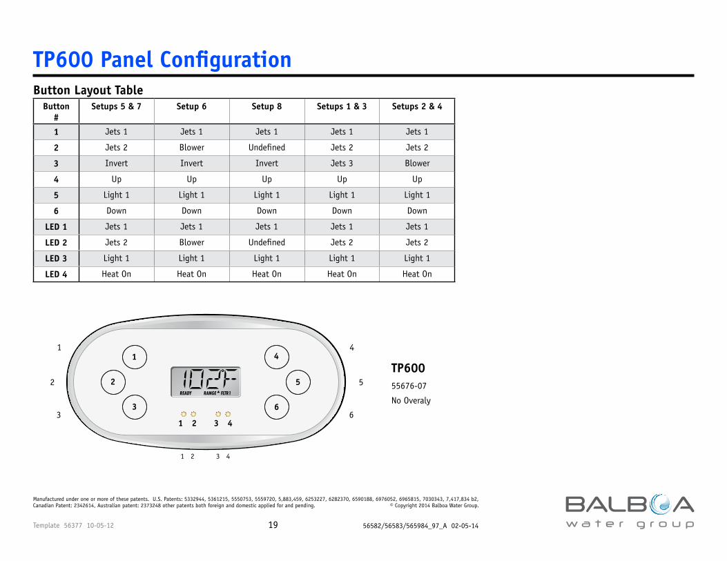
Button Layout Table Button
#Setups 5 & 7 Setup 6 Setup 8 Setups 1 & 3 Setups 2 & 4
1 Jets 1 Jets 1 Jets 1 Jets 1 Jets 1
2 Jets 2 Blower Undefined Jets 2 Jets 2
3 Invert Invert Invert Jets 3 Blower
4 Up Up Up Up Up
5 Light 1 Light 1 Light 1 Light 1 Light 1
6 Down Down Down Down Down
LED 1 Jets 1 Jets 1 Jets 1 Jets 1 Jets 1
LED 2 Jets 2 Blower Undefined Jets 2 Jets 2
LED 3 Light 1 Light 1 Light 1 Light 1 Light 1
LED 4 Heat On Heat On Heat On Heat On Heat On
TP600 Panel Configuration
READY RANGE FLTR1
1
2
3
4
5
6
1 2 3 4
1 2 3 4
1 4
2 5
3 6
TP60055676-07
No Overaly
Template 56377 10-05-12 56582/56583/565984_97_A 02-05-1420
Manufactured under one or more of these patents. U.S. Patents: 5332944, 5361215, 5550753, 5559720, 5,883,459, 6253227, 6282370, 6590188, 6976052, 6965815, 7030343, 7,417,834 b2, Canadian Patent: 2342614, Australian patent: 2373248 other patents both foreign and domestic applied for and pending. © Copyright 2014 Balboa Water Group.
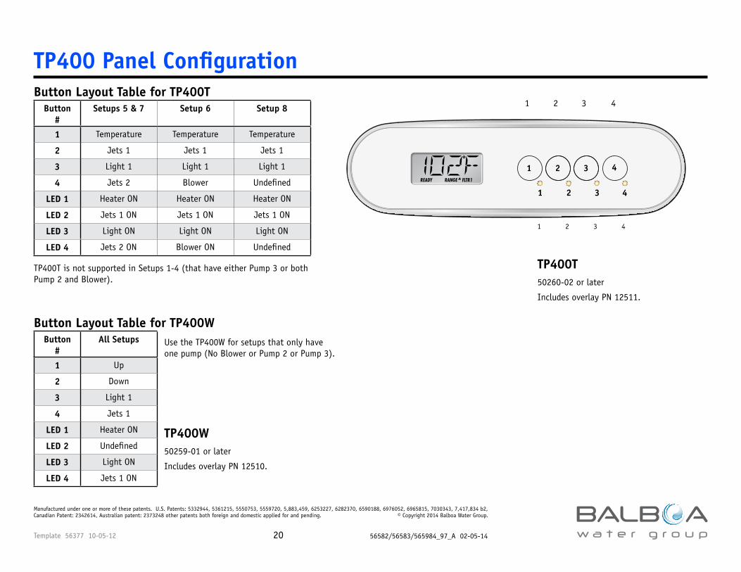
Button Layout Table for TP400TButton
#Setups 5 & 7 Setup 6 Setup 8
1 Temperature Temperature Temperature
2 Jets 1 Jets 1 Jets 1
3 Light 1 Light 1 Light 1
4 Jets 2 Blower Undefined
LED 1 Heater ON Heater ON Heater ON
LED 2 Jets 1 ON Jets 1 ON Jets 1 ON
LED 3 Light ON Light ON Light ON
LED 4 Jets 2 ON Blower ON Undefined
Button Layout Table for TP400WButton
#All Setups
1 Up
2 Down
3 Light 1
4 Jets 1
LED 1 Heater ON
LED 2 Undefined
LED 3 Light ON
LED 4 Jets 1 ON
TP400 Panel Configuration
1 2 3 4
1 2 3 4
1 2 3 4
1 2 3 4
TP400T50260-02 or later
Includes overlay PN 12511.
TP400W50259-01 or later
Includes overlay PN 12510.
Use the TP400W for setups that only have one pump (No Blower or Pump 2 or Pump 3).
TP400T is not supported in Setups 1-4 (that have either Pump 3 or both Pump 2 and Blower).
Template 56377 10-05-12 56582/56583/565984_97_A 02-05-1421
Manufactured under one or more of these patents. U.S. Patents: 5332944, 5361215, 5550753, 5559720, 5,883,459, 6253227, 6282370, 6590188, 6976052, 6965815, 7030343, 7,417,834 b2, Canadian Patent: 2342614, Australian patent: 2373248 other patents both foreign and domestic applied for and pending. © Copyright 2014 Balboa Water Group.
BP501 Configuration OptionsAuxilliary Panel Features on Bank 1*Feature Default Aux Button A1 Jets 1
Aux Button A2 Jets 2
Aux Button A3 Jets 3 in Setups 1 & 3 Blower in Setups 2, 4 & 6 Undefined in Setups 5, 7 & 8
Aux Button A4 Light
*Bank 1 consists of J5 on the Main Circuit Board.
Aux Connection Splitter PN25257 may be required.
Buttons that are assigned to equipment that is not defined in a Setup will not do anything in that Setup.
Template 56377 10-05-12 56582/56583/565984_97_A 02-05-1422
Manufactured under one or more of these patents. U.S. Patents: 5332944, 5361215, 5550753, 5559720, 5,883,459, 6253227, 6282370, 6590188, 6976052, 6965815, 7030343, 7,417,834 b2, Canadian Patent: 2342614, Australian patent: 2373248 other patents both foreign and domestic applied for and pending. © Copyright 2014 Balboa Water Group.
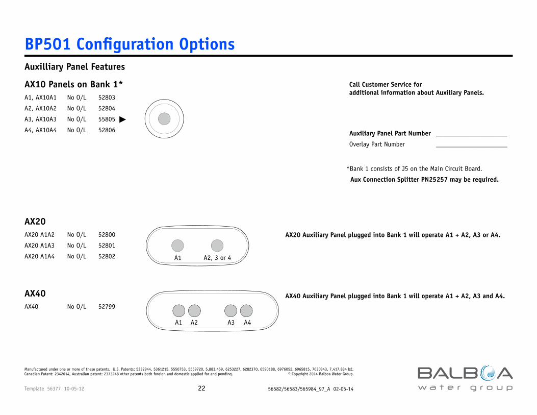
Auxilliary Panel Features
AX10 Panels on Bank 1*A1, AX10A1 No O/L 52803
A2, AX10A2 No O/L 52804
A3, AX10A3 No O/L 55805 �
A4, AX10A4 No O/L 52806
AX20AX20 A1A2 No O/L 52800
AX20 A1A3 No O/L 52801
AX20 A1A4 No O/L 52802
AX40AX40 No O/L 52799
BP501 Configuration Options
A1 A2, 3 or 4
A1 A2 A3 A4
Call Customer Service for additional information about Auxiliary Panels.
AX20 Auxiliary Panel plugged into Bank 1 will operate A1 + A2, A3 or A4.
AX40 Auxiliary Panel plugged into Bank 1 will operate A1 + A2, A3 and A4.
Auxiliary Panel Part Number _____________________
Overlay Part Number _____________________
*Bank 1 consists of J5 on the Main Circuit Board.
Aux Connection Splitter PN25257 may be required.
Jets 1Jets 1BlowerBlower