Embed Size (px)
Citation preview
i
BPA MOD-032 Model Data
Requirements & Reporting
Procedures
(supplement to WECC Data Preparation Manual)
Version 1.3
April 19, 2017

BPA ii
This Page Left Intentionally Blank
BPA i
Contents
1 Introduction ......................................................................................................................... 1
1.1 Purpose ....................................................................................................................... 1
1.2 Process Overview ........................................................................................................ 1
1.3 Responsible Entities .................................................................................................... 2
1.4 Typical Scenarios......................................................................................................... 2
1.5 Schedule ...................................................................................................................... 3
2 Data Submission Requirement ............................................................................................ 4
2.1 Generator Owner ......................................................................................................... 4
2.2 Transmission Owner .................................................................................................... 4
2.3 Data Submission Process and Format ......................................................................... 5
3 Steady State Model Development ....................................................................................... 1
3.1 Level of Detail .............................................................................................................. 1
3.1.1 Definitions ............................................................................................................. 1
3.1.1.1 Data Types .................................................................................................... 1
3.1.1.2 Project Statuses ............................................................................................. 2
3.1.2 Modeling Criteria ................................................................................................... 2
3.1.3 Ratings ................................................................................................................. 2
3.1.4 Modeling of Wind Farms and PV Power Plants ..................................................... 3
4 Dynamics Model Development ............................................................................................ 4
4.1 Level of Detail .............................................................................................................. 4
4.1.1 Generators ............................................................................................................ 4
4.1.2 Static VAR Compensators & Synchronous Condensers ....................................... 5
4.1.3 HVDC ................................................................................................................... 5
4.1.4 Load ..................................................................................................................... 5
4.1.5 Additional Protection Relays ................................................................................. 6
4.2 Dynamics Data Checks ................................................................................................ 6
5 Short Circuit Model Development ........................................................................................ 7
5.1 Level of Detail .............................................................................................................. 7
6 MOD-032 - Attachment 1 .................................................................................................... 8
7 Version Control Block:........................................................................................................10
BPA 1
1 Introduction
1.1 Purpose The Western Electricity Coordinating Council (WECC) develops a series of power flow and
dynamics simulation models which are used by Bonneville Power Administration (BPA) and its
customers for performing planning and operational reliability and economic studies needed to
fulfill various North American Electric Reliability Corporation (NERC) and Tariff compliance
obligations.
Pursuant to requirement R1 of MOD-0321, BPA as a registered Planning Coordinator (PC) and
its registered Transmission Planners (TPs) have jointly established a set of common procedures
for submitting data needed for developing the WECC interconnection planning models.
The purpose of this document is to outline these data reporting procedures needed to support
the development of power flow and dynamics simulation base case models in a manner
compliant with MOD-032 that realistically simulate steady state and dynamic behavior of the
transmission system. Data requirements outlined in this document are intended to be
consistent with the requirements outlined in the WECC Data Preparation Manual (DPM). In the
event of an inconsistency, the WECC DPM supersedes this process document. If this
document requires data not in the WECC DPM then this document takes precedence for that
data.
See: WECC Data Preparation Manual at the SRWG portal under the menu item “Data Preparation manual.”
The PC is also responsible for submitting models for its planning area to the Electric Reliability
Organization (ERO) designee per MOD-032 Requirement R4. This responsibility may be
delegated to TPs in BPAs PC area.
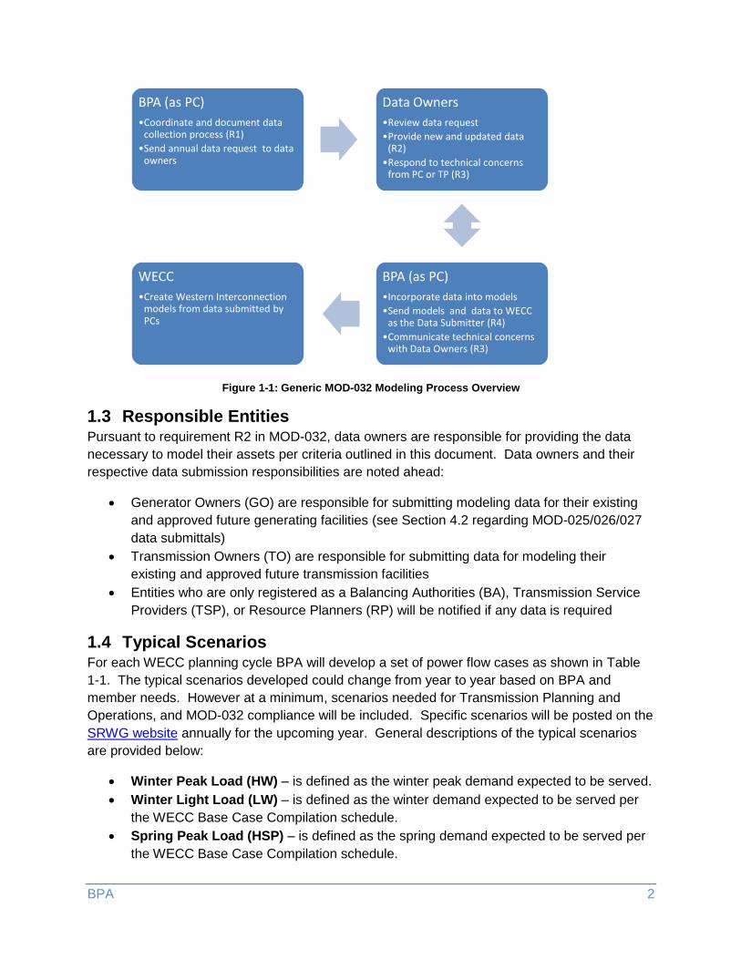
1.2 Process Overview Figure 1-1 provides a high-level overview of the data submission process. Additional details on
the data submission processes are outlined in Sections 3 & 4.
Data requests will typically come from BPA’s Customer Service Reliability Program (CSRP)
team. When sending data or otherwise communicating with BPA, please use CSRP’s team
mailbox: [email protected].
1 http://www.nerc.com/_layouts/PrintStandard.aspx?standardnumber=MOD-032-1&title=Data for Power
System Modeling and Analysis
BPA 2
Figure 1-1: Generic MOD-032 Modeling Process Overview
1.3 Responsible Entities Pursuant to requirement R2 in MOD-032, data owners are responsible for providing the data
necessary to model their assets per criteria outlined in this document. Data owners and their
respective data submission responsibilities are noted ahead:
Generator Owners (GO) are responsible for submitting modeling data for their existing
and approved future generating facilities (see Section 4.2 regarding MOD-025/026/027
data submittals)
Transmission Owners (TO) are responsible for submitting data for modeling their
existing and approved future transmission facilities
Entities who are only registered as a Balancing Authorities (BA), Transmission Service
Providers (TSP), or Resource Planners (RP) will be notified if any data is required
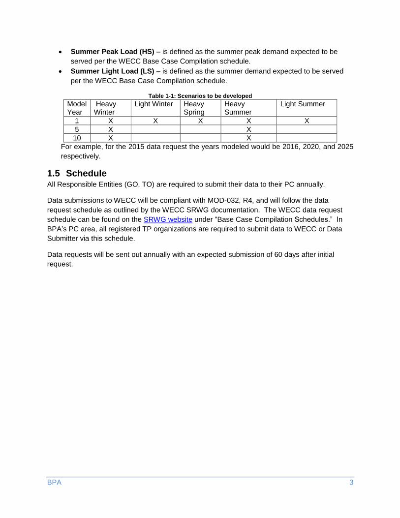
1.4 Typical Scenarios For each WECC planning cycle BPA will develop a set of power flow cases as shown in Table
1-1. The typical scenarios developed could change from year to year based on BPA and
member needs. However at a minimum, scenarios needed for Transmission Planning and
Operations, and MOD-032 compliance will be included. Specific scenarios will be posted on the
SRWG website annually for the upcoming year. General descriptions of the typical scenarios
are provided below:
Winter Peak Load (HW) – is defined as the winter peak demand expected to be served.
Winter Light Load (LW) – is defined as the winter demand expected to be served per
the WECC Base Case Compilation schedule.
Spring Peak Load (HSP) – is defined as the spring demand expected to be served per
the WECC Base Case Compilation schedule.
BPA (as PC)
•Coordinate and document data collection process (R1)
•Send annual data request to data owners
Data Owners
•Review data request
•Provide new and updated data (R2)
•Respond to technical concerns from PC or TP (R3)
BPA (as PC)
•Incorporate data into models
•Send models and data to WECC as the Data Submitter (R4)
•Communicate technical concerns with Data Owners (R3)
WECC
•Create Western Interconnection models from data submitted by PCs
BPA 3
Summer Peak Load (HS) – is defined as the summer peak demand expected to be
served per the WECC Base Case Compilation schedule.
Summer Light Load (LS) – is defined as the summer demand expected to be served
per the WECC Base Case Compilation schedule.
Table 1-1: Scenarios to be developed
Model Year
Heavy Winter
Light Winter Heavy Spring
Heavy Summer
Light Summer
1 X X X X X
5 X X
10 X X
For example, for the 2015 data request the years modeled would be 2016, 2020, and 2025
respectively.
1.5 Schedule All Responsible Entities (GO, TO) are required to submit their data to their PC annually.
Data submissions to WECC will be compliant with MOD-032, R4, and will follow the data
request schedule as outlined by the WECC SRWG documentation. The WECC data request
schedule can be found on the SRWG website under “Base Case Compilation Schedules.” In
BPA’s PC area, all registered TP organizations are required to submit data to WECC or Data
Submitter via this schedule.
Data requests will be sent out annually with an expected submission of 60 days after initial
request.
BPA 4
2 Data Submission Requirement MOD-032 Attachment 1 lists the minimum modeling data to be requested per the standard and
is summarized by responsible entity below. Section 6 includes Attachment 1 for reference.
BPA as a PC will confirm an entity’s participation in fulfilling their modeling
obligation/compliance with MOD-032, R2. Below sections also summarize additional data
requested in BPA’s PC area. A data request spreadsheet might be sent annually to customers
and outlines data needed that year.
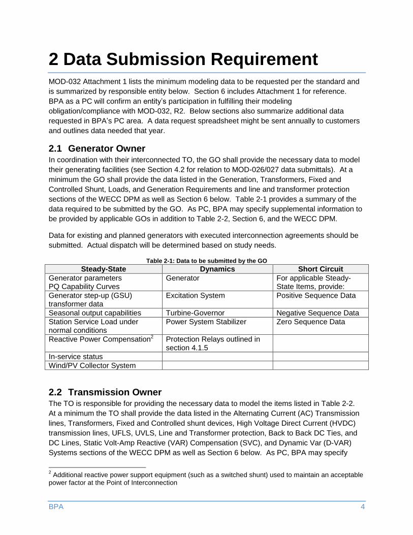
2.1 Generator Owner In coordination with their interconnected TO, the GO shall provide the necessary data to model
their generating facilities (see Section 4.2 for relation to MOD-026/027 data submittals). At a
minimum the GO shall provide the data listed in the Generation, Transformers, Fixed and
Controlled Shunt, Loads, and Generation Requirements and line and transformer protection
sections of the WECC DPM as well as Section 6 below. Table 2-1 provides a summary of the
data required to be submitted by the GO. As PC, BPA may specify supplemental information to
be provided by applicable GOs in addition to Table 2-2, Section 6, and the WECC DPM.
Data for existing and planned generators with executed interconnection agreements should be
submitted. Actual dispatch will be determined based on study needs.
Table 2-1: Data to be submitted by the GO
Steady-State Dynamics Short Circuit
Generator parameters PQ Capability Curves
Generator For applicable Steady-State Items, provide:
Generator step-up (GSU) transformer data
Excitation System Positive Sequence Data
Seasonal output capabilities Turbine-Governor Negative Sequence Data
Station Service Load under normal conditions
Power System Stabilizer Zero Sequence Data
Reactive Power Compensation2 Protection Relays outlined in section 4.1.5
In-service status
Wind/PV Collector System
2.2 Transmission Owner The TO is responsible for providing the necessary data to model the items listed in Table 2-2.
At a minimum the TO shall provide the data listed in the Alternating Current (AC) Transmission
lines, Transformers, Fixed and Controlled shunt devices, High Voltage Direct Current (HVDC)
transmission lines, UFLS, UVLS, Line and Transformer protection, Back to Back DC Ties, and
DC Lines, Static Volt-Amp Reactive (VAR) Compensation (SVC), and Dynamic Var (D-VAR)
Systems sections of the WECC DPM as well as Section 6 below. As PC, BPA may specify
2 Additional reactive power support equipment (such as a switched shunt) used to maintain an acceptable
power factor at the Point of Interconnection
BPA 5
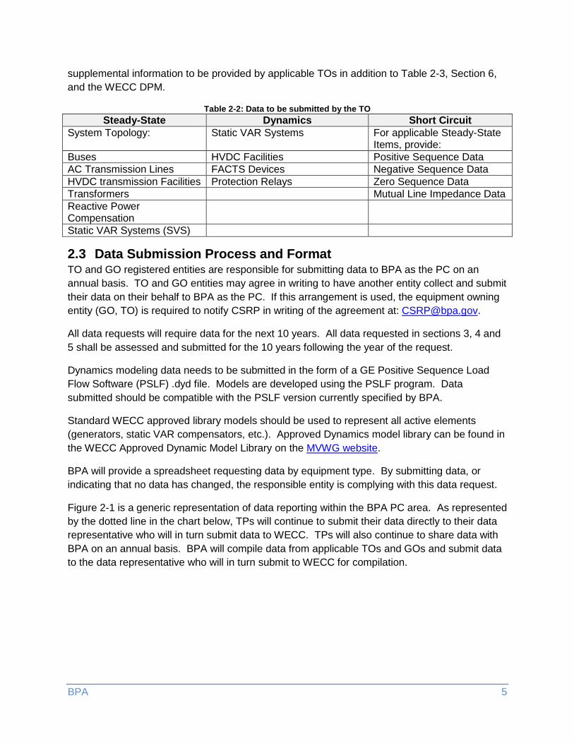
supplemental information to be provided by applicable TOs in addition to Table 2-3, Section 6,
and the WECC DPM.
Table 2-2: Data to be submitted by the TO
Steady-State Dynamics Short Circuit
System Topology: Static VAR Systems For applicable Steady-State Items, provide:
Buses HVDC Facilities Positive Sequence Data
AC Transmission Lines FACTS Devices Negative Sequence Data
HVDC transmission Facilities Protection Relays Zero Sequence Data
Transformers Mutual Line Impedance Data
Reactive Power Compensation
Static VAR Systems (SVS)
2.3 Data Submission Process and Format TO and GO registered entities are responsible for submitting data to BPA as the PC on an
annual basis. TO and GO entities may agree in writing to have another entity collect and submit
their data on their behalf to BPA as the PC. If this arrangement is used, the equipment owning
entity (GO, TO) is required to notify CSRP in writing of the agreement at: [email protected].
All data requests will require data for the next 10 years. All data requested in sections 3, 4 and
5 shall be assessed and submitted for the 10 years following the year of the request.
Dynamics modeling data needs to be submitted in the form of a GE Positive Sequence Load
Flow Software (PSLF) .dyd file. Models are developed using the PSLF program. Data
submitted should be compatible with the PSLF version currently specified by BPA.
Standard WECC approved library models should be used to represent all active elements
(generators, static VAR compensators, etc.). Approved Dynamics model library can be found in
the WECC Approved Dynamic Model Library on the MVWG website.
BPA will provide a spreadsheet requesting data by equipment type. By submitting data, or
indicating that no data has changed, the responsible entity is complying with this data request.
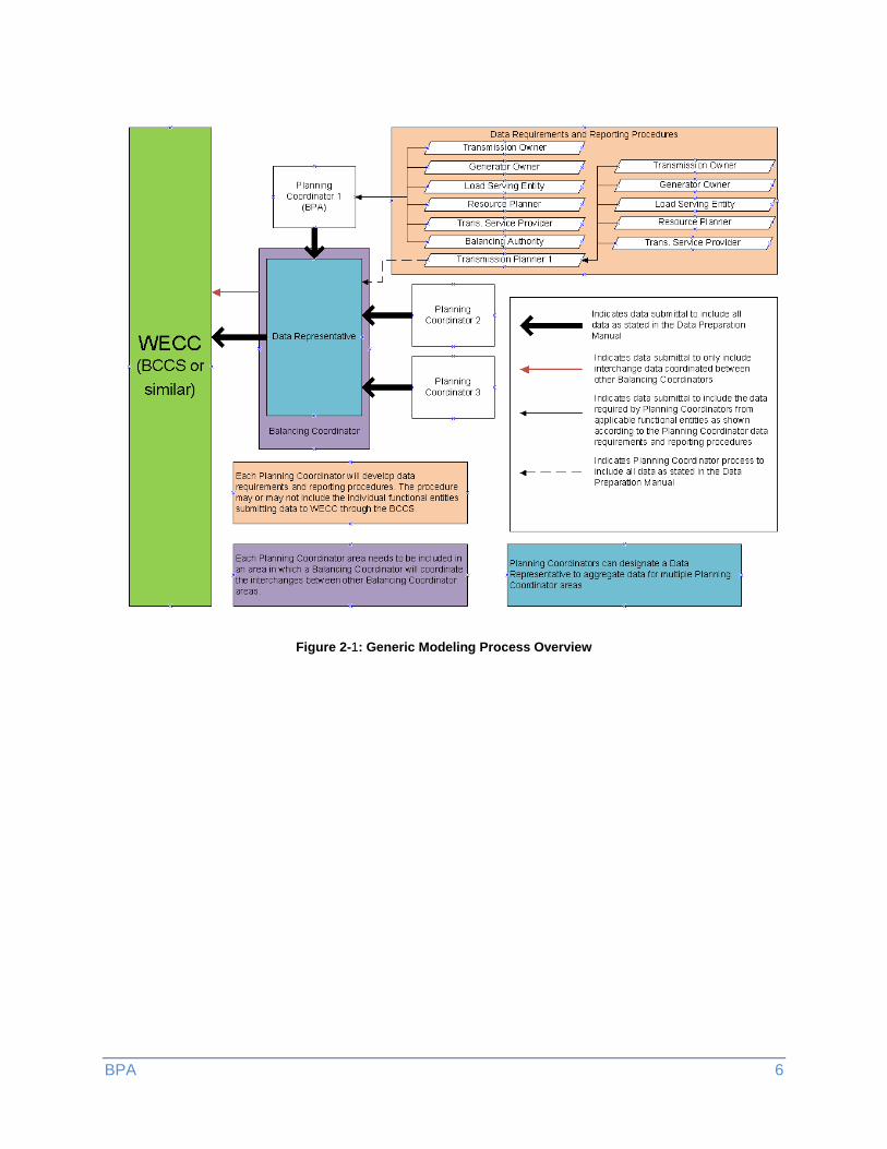
Figure 2-1 is a generic representation of data reporting within the BPA PC area. As represented
by the dotted line in the chart below, TPs will continue to submit their data directly to their data
representative who will in turn submit data to WECC. TPs will also continue to share data with
BPA on an annual basis. BPA will compile data from applicable TOs and GOs and submit data
to the data representative who will in turn submit to WECC for compilation.
BPA 6
Figure 2-1: Generic Modeling Process Overview
BPA 1
3 Steady State Model Development
3.1 Level of Detail On at least an annual basis each data owner is required to submit the following model data to
BPA for incorporation into the Power Flow Model database:
1. Transmission projects that are Planned and Funded or In Service.
2. Generators with executed Generator Interconnection Agreements (GIA)3 and associated
network upgrades. At a minimum, all generators with a nameplate 10 MVA or larger or a
facility with an aggregated nameplate 20 MVA or larger must be modeled in detail and
are to be submitted by applicable GOs.
3. Bus/load/generation and devices profiles, which include:
a. Load forecast for each month at the bus level representing a coincident with the
company peak.
b. Corresponding generation limits and level (Pmin, Pmax, Qmin, Qmax, and
Pgen); Generation limits to be submitted by GO, Generation level to be submitted
by TOs.
c. Settings on regulating equipment such as transformers, switched shunts and
HVDC data; to be submitted by data owner.
4. Updates and/or corrections to approved future generation and transmission projects.
5. Any corrections that need to be made to existing system data modeling in the WECC
Base Cases. Data owners shall provide facility retirement updates.
6. Any other information requested by BPA, as the PC, that BPA deemed necessary for
modeling.
GOs will coordinate with their interconnected TO in order to ensure that their data is consistent
with the TO submitted topology. GOs may submit their data directly to BPA or work with their
interconnected TO to submit the data to BPA on their behalf. If GO’s have made arrangements
with their interconnected TO to submit data on their behalf, this must be communicated in
writing to BPA at: [email protected].
If the data has not changed since the last submission, data owners will have the option of indicating that the data has not changed in the attached data request spreadsheet. The data submitted must be sufficient to perform reliability and economic studies on the bulk
electric system (BES) as defined by NERC4. To that extent, relevant data associated with sub-
BES facilities may also need to be provided.
3.1.1 Definitions
3.1.1.1 Data Types
Steady State: Data required to represent the normal operation of the power system.
3 http://www.bpa.gov/transmission/Doing%20Business/Tariff/Pages/default.aspx
4 http://www.nerc.com/pa/RAPA/BES%20DL/bes_phase2_reference_document_20140325_final_clean.pdf
BPA 2
Dynamics: Data necessary to support the analysis of the power system stability.
Short Circuit: Positive, Negative, and Zero sequence data as well as any mutual line
impedance data.
3.1.1.2 Project Statuses
Conceptual: Conceptual or vision plans
Proposed: Projects that require additional review and are subject to change
Planned-Funded: Projects that have completed the planning process and there is intent
to permit and construct the project
In Service: In Service
Corrections: Base case change to be submitted for correction of all future Base Cases
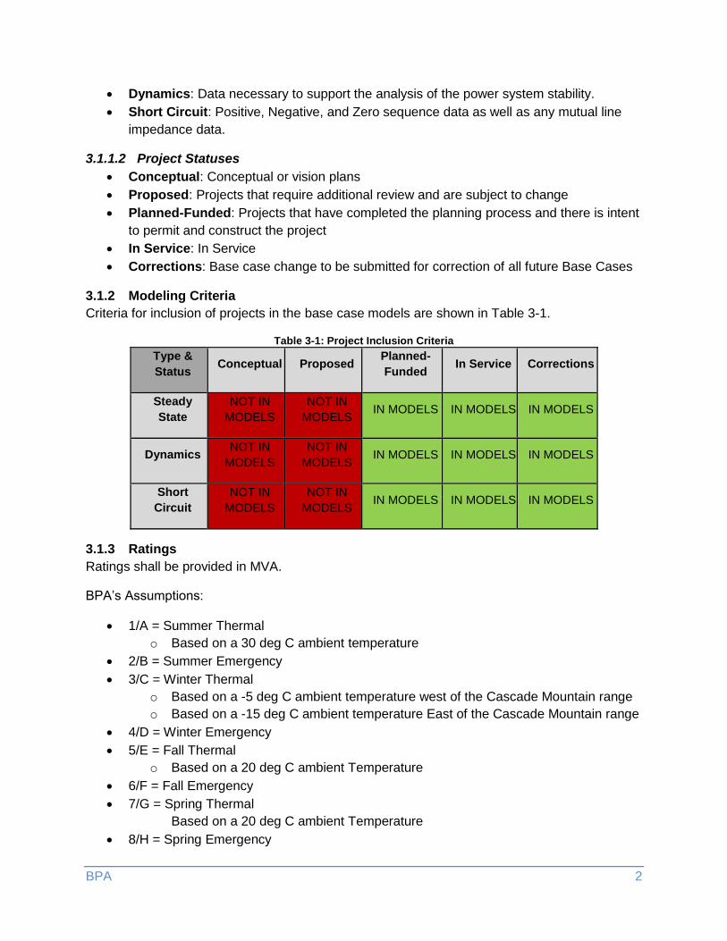
3.1.2 Modeling Criteria
Criteria for inclusion of projects in the base case models are shown in Table 3-1.
Table 3-1: Project Inclusion Criteria
Type &
Status Conceptual Proposed
Planned-
Funded In Service Corrections
Steady
State
NOT IN
MODELS
NOT IN
MODELS IN MODELS IN MODELS IN MODELS
Dynamics NOT IN
MODELS
NOT IN
MODELS IN MODELS IN MODELS IN MODELS
Short
Circuit
NOT IN
MODELS
NOT IN
MODELS IN MODELS IN MODELS IN MODELS
3.1.3 Ratings
Ratings shall be provided in MVA.
BPA’s Assumptions:
1/A = Summer Thermal
o Based on a 30 deg C ambient temperature
2/B = Summer Emergency
3/C = Winter Thermal
o Based on a -5 deg C ambient temperature west of the Cascade Mountain range
o Based on a -15 deg C ambient temperature East of the Cascade Mountain range
4/D = Winter Emergency
5/E = Fall Thermal
o Based on a 20 deg C ambient Temperature
6/F = Fall Emergency
7/G = Spring Thermal
Based on a 20 deg C ambient Temperature
8/H = Spring Emergency
BPA 3
3.1.4 Modeling of Wind Farms and PV Power Plants
Wind and photovoltaic projects shall be represented through an equivalent generator(s), equivalent low-voltage to intermediate-voltage transformer, equivalent collector system, and substation transformer between the collector system and the transmission bus.
Also: WECC Wind Power Plant Power Flow Modeling Guide and PV Plant Power Flow Modeling Guide
BPA 4
4 Dynamics Model Development
4.1 Level of Detail Dynamics simulations analyze the transient response of the power system following a
disturbance. These simulations are in a timeframe of 0 to 20 seconds with a typical time step of
¼ cycle. As such it is necessary to develop a model that sufficiently represents the automatic
response of all active elements to a disturbance on the power system.
On an annual basis each data owner is required to submit the following model data:
Dynamic models to represent approved future active elements such as but not limited to
generators, Flexible Alternating Current Transmission System (FACTS) devices, or fast
switching shunts.
Updates to existing dynamic models.
If the data has not changed since the last submission, indicate that the data has not
changed in the attached data request spreadsheet.
Data will not be requested from GO’s whose models for their generator type are still
under development within WECC.
Dynamics data submitted annually for MOD-032 is in addition to requirements in the BPA “GO
Model Data Submission Process” document.
A separate request will be sent every 5 years per the BPA “GO Model Data Submission
Process” document that requires testing and new data be submitted. All applicable entities
must still adhere to all requirements and data collection procedures outlined by BPA’s “GO
Model Data Submission Process” document. BPA’s “GO Model Data Submission Process”
document is available on request by emailing: [email protected].
GOs are expected to submit directly to BPA unless they have made arrangements with the
interconnecting TO to submit data on their behalf. If this arrangement is used, it must be
communicated in writing to BPA at: [email protected].
4.1.1 Generators
At a minimum, all generators with a nameplate 10 MVA or larger or a facility with an aggregated
nameplate 20 MVA or larger must be modeled in detail. A detailed model of a generator must
include:
Generator Model
Excitation System Model
o May be omitted if unit is operated under manual excitation control
Turbine-Governor Model
o May be omitted if unit doesn’t regulate frequency
Power System Stabilizer Model
o May be omitted if device is not installed or not active
BPA 5
Reactive Line Drop Compensation Model
o May be omitted if device is not installed or not active
Over Excitation Limiter
o May be omitted if device is not installed or not active
Under Voltage Ride Through Relays
o May be omitted if device is not installed or not active
Under Frequency Ride Through Relays
o May be omitted if device is not installed or not active
Generators with detailed modeling must use a dynamic model from the WECC Approved
Dynamic Model Library found on the MVWG website. If a suitable model is not in the approved
library the data submitter may request a model be added to the standard list by providing BPA
with a technical justification for doing so. BPA will present the technical justification to the
MVWG for approval and inform the data submitter if the model has been accepted or not.
Several legacy models have been omitted from the WECC Approved Dynamic Model Library
since they can be directly converted to newer dynamic models with minimal effort and without
changes to simulation results. In instances where detailed dynamic modeling is unavailable,
generic data may be used. Generators without detailed modeling will be netted.
4.1.2 Static VAR Compensators & Synchronous Condensers
SVC and synchronous condensers are reactive power devices that can vary the amount of
reactive power supplied or absorbed within the simulated timeframe (0-20 seconds). These
devices must be modeled in sufficient detail in order to simulate its expected behavior.
4.1.3 HVDC
All HVDC transmission facilities must be represented with a sufficiently detailed model to
simulate its expected behavior. For future HVDC transmission facilities where exact design
specifications are not known generic HVDC models should be used.
4.1.4 Load
The dynamic behavior of load must be modeled in sufficient detail to meet NERC TPL and TOP
compliance obligations. Providing a specific dynamic load characteristic model or the load
composition is acceptable.
The composition of the load shall be defined as referenced in the MVWG Load Long ID
Instructions. Based on the composition of the load, an appropriate dynamic representation will
be developed using models available in the PSLF dynamics library, likely a composite load
model (CMLD).
Dynamics models for UVLS and UFLS are required when installed. Approved models can be
found in the WECC Approved Dynamic Model Library found on the MVWG website.
BPA 6
4.1.5 Additional Protection Relays
Generic protection relays are applied during the simulation that scan for bus voltages, out-of-
step conditions, and against generic protection zones for transmission lines. These generic
protection relays only monitor system conditions.
Equipment specific detailed protection relays may also be submitted at the discretion of the data
owner; however, detailed protection relay models need to be submitted when:
Voltage and frequency ride through capabilities of any generation facility with this
capability are present.
3-phase over current relays are required and is the primary protection.
Other relay models are required by the WECC DPM or the WECC Approved Dynamic
Model Implementation Schedule
4.2 Dynamics Data Checks Once the dynamic models are created, a set of data checks to flag potential issues with the data
submitted will be performed. In addition to the data checks, a sample set of disturbances are
run to assist in model review. Dynamics data checks are documented in the BPA “GO Model
Data Submission Process” document for MOD-026 and MOD-027.
BPA 7
5 Short Circuit Model Development
5.1 Level of Detail Short circuit data is required for all generators, shunts, transformers, and lines that are required
to be submitted in sections 3 or 4.
MOD-032 requires that short circuit data should be shared openly between applicable NERC
functional entities. Applicable entities are responsible to submit their positive, negative, and
zero sequence data for all applicable pieces of equipment. TOs are also responsible for
submitting any mutual impedance data.
This data will only be shared with WECC as requested and not part of regular (MOD-032 R4)
data submittals. This is because WECC does not currently create interconnection-wide cases
for the use of short circuit analysis.
BPA 8
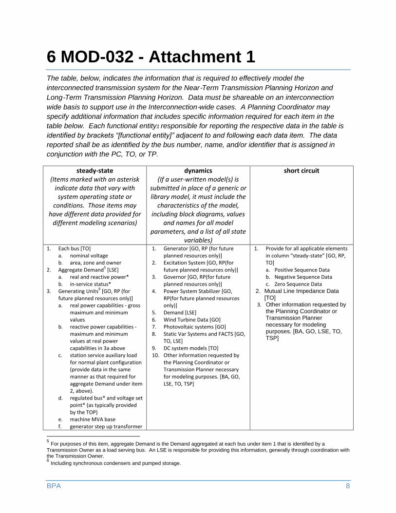
6 MOD-032 - Attachment 1 The table, below, indicates the information that is required to effectively model the
interconnected transmission system for the Near‐Term Transmission Planning Horizon and
Long‐Term Transmission Planning Horizon. Data must be shareable on an interconnection
wide basis to support use in the Interconnection‐wide cases. A Planning Coordinator may
specify additional information that includes specific information required for each item in the
table below. Each functional entity1 responsible for reporting the respective data in the table is
identified by brackets “[functional entity]” adjacent to and following each data item. The data
reported shall be as identified by the bus number, name, and/or identifier that is assigned in
conjunction with the PC, TO, or TP.
steady-state (Items marked with an asterisk
indicate data that vary with system operating state or
conditions. Those items may have different data provided for
different modeling scenarios)
dynamics (If a user-written model(s) is
submitted in place of a generic or library model, it must include the
characteristics of the model, including block diagrams, values
and names for all model parameters, and a list of all state
variables)
short circuit
1. Each bus [TO] a. nominal voltage b. area, zone and owner
2. Aggregate Demand5 [LSE]
a. real and reactive power* b. in-service status*
3. Generating Units6 [GO, RP (for
future planned resources only)] a. real power capabilities - gross
maximum and minimum values
b. reactive power capabilities - maximum and minimum values at real power capabilities in 3a above
c. station service auxiliary load for normal plant configuration (provide data in the same manner as that required for aggregate Demand under item 2, above).
d. regulated bus* and voltage set point* (as typically provided by the TOP)
e. machine MVA base f. generator step up transformer
1. Generator [GO, RP (for future planned resources only)]
2. Excitation System [GO, RP(for future planned resources only)]
3. Governor [GO, RP(for future planned resources only)]
4. Power System Stabilizer [GO, RP(for future planned resources only)]
5. Demand [LSE] 6. Wind Turbine Data [GO] 7. Photovoltaic systems [GO] 8. Static Var Systems and FACTS [GO,
TO, LSE] 9. DC system models [TO] 10. Other information requested by
the Planning Coordinator or Transmission Planner necessary for modeling purposes. [BA, GO, LSE, TO, TSP]
1. Provide for all applicable elements in column “steady-state” [GO, RP, TO] a. Positive Sequence Data b. Negative Sequence Data c. Zero Sequence Data
2. Mutual Line Impedance Data [TO]
3. Other information requested by the Planning Coordinator or Transmission Planner necessary for modeling purposes. [BA, GO, LSE, TO, TSP]
5 For purposes of this item, aggregate Demand is the Demand aggregated at each bus under item 1 that is identified by a
Transmission Owner as a load serving bus. An LSE is responsible for providing this information, generally through coordination with the Transmission Owner. 6 Including synchronous condensers and pumped storage.
BPA 9
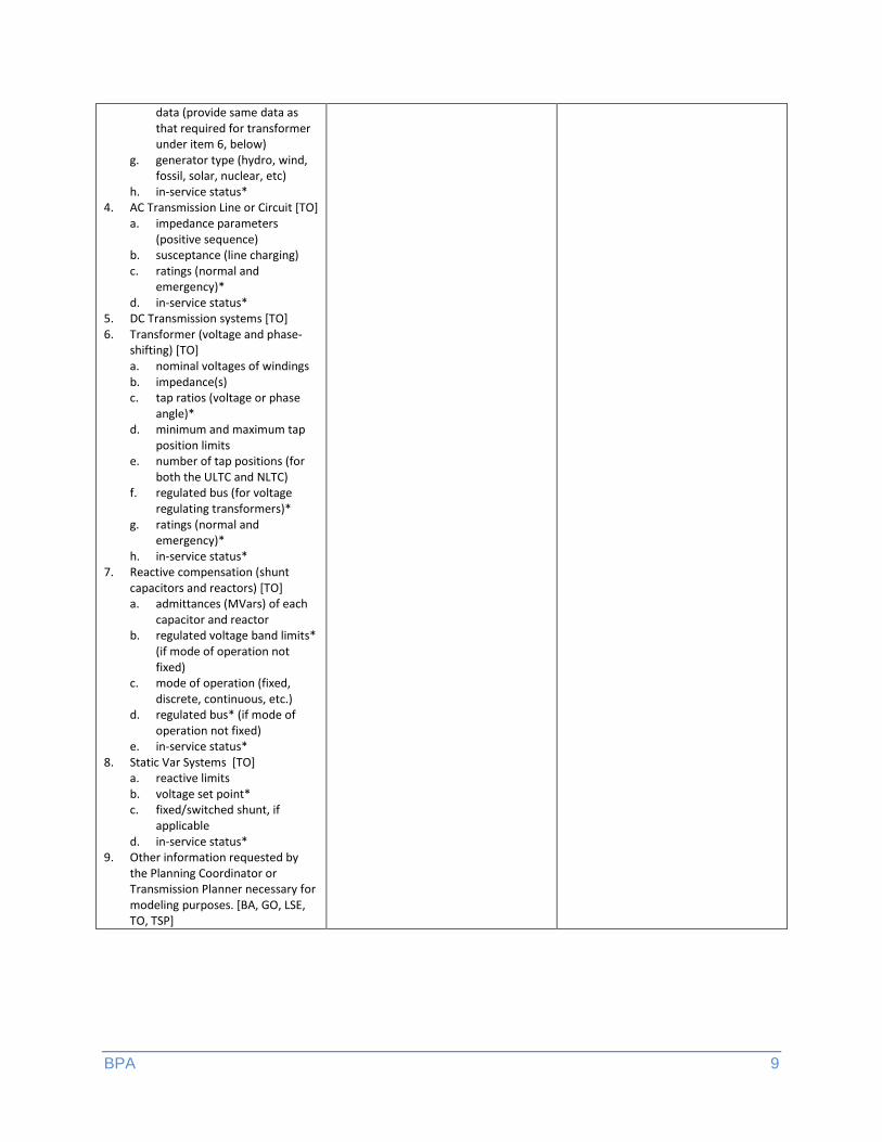
data (provide same data as that required for transformer under item 6, below)
g. generator type (hydro, wind, fossil, solar, nuclear, etc)
h. in-service status* 4. AC Transmission Line or Circuit [TO]
a. impedance parameters (positive sequence)
b. susceptance (line charging) c. ratings (normal and
emergency)* d. in-service status*
5. DC Transmission systems [TO] 6. Transformer (voltage and phase-
shifting) [TO] a. nominal voltages of windings b. impedance(s) c. tap ratios (voltage or phase
angle)* d. minimum and maximum tap
position limits e. number of tap positions (for
both the ULTC and NLTC) f. regulated bus (for voltage
regulating transformers)* g. ratings (normal and
emergency)* h. in-service status*
7. Reactive compensation (shunt capacitors and reactors) [TO] a. admittances (MVars) of each
capacitor and reactor b. regulated voltage band limits*
(if mode of operation not fixed)
c. mode of operation (fixed, discrete, continuous, etc.)
d. regulated bus* (if mode of operation not fixed)
e. in-service status* 8. Static Var Systems [TO]
a. reactive limits b. voltage set point* c. fixed/switched shunt, if
applicable d. in-service status*
9. Other information requested by the Planning Coordinator or Transmission Planner necessary for modeling purposes. [BA, GO, LSE, TO, TSP]
BPA 10
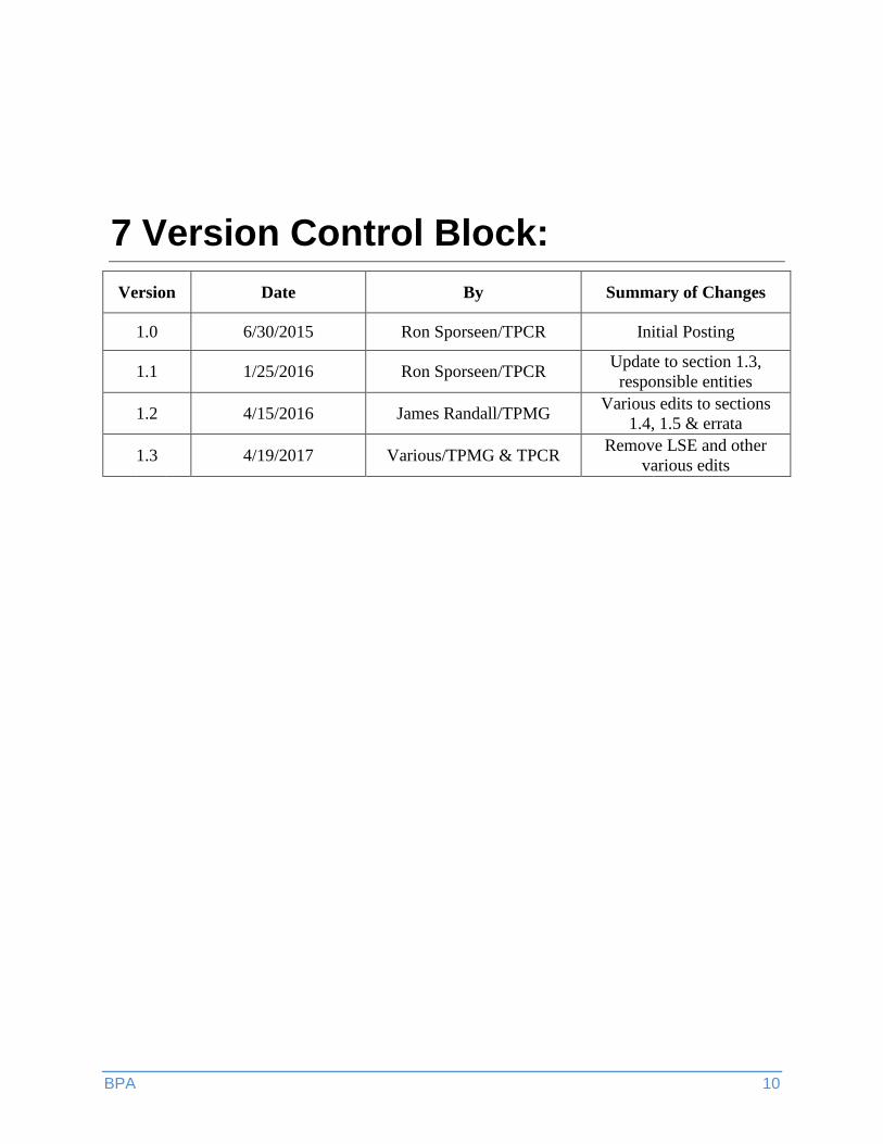
7 Version Control Block:
Version Date By Summary of Changes
1.0 6/30/2015 Ron Sporseen/TPCR Initial Posting
1.1 1/25/2016 Ron Sporseen/TPCR Update to section 1.3,
responsible entities
1.2 4/15/2016 James Randall/TPMG Various edits to sections
1.4, 1.5 & errata
1.3 4/19/2017 Various/TPMG & TPCR Remove LSE and other
various edits