Embed Size (px)
Citation preview
UMTA-MA- 06 -0029-74 -2
BRAKING SYSTEM INTEGRATIONIN DUAL MODE SYSTEMS
document is available to the publicthrough the national technicalINFORMATION SERVICE. SPRINGFIELDVIRGINIA 22151.
Prepared for
U.s. DEPARTMENT OF TRANSPORTATIONURBAN MASS TRANSPORTATION ADMINISTRATION
Office of Research & DevelopmentWashington DC 20591
Jeffrey J. Bowe
Oi 1°
MAY 1974
FINAL REPORT
NOTICE
This document is disseminated under the sponsorshipof the Department of Transportation in the interestof information exchange. The United States Govern-ment assumes no liability for its contents or uset hereof.
NOTICE
The United States Government does not endorseproducts or manufacturers. Trade or manufacturers'names appear herein solely because they are con-sidered essential to the object of this report.
l?.z>
Mlnt>.
~3>oT-
T-SC-
mM-?T1
rttAtf^onnlrioi
T echnicfl $0fo$'6n<!lfffi4
n p°9 e
1 . Report No.
UMTA-MA- 06-0029-74-2
2. Government Accession No.
4. Title and Subtitle
BRAKING SYSTEM INTEGRATIONIN DUAL MODE SYSTEMS
7. Authors)
Jeffrey J. Bowe
3. Recipient's Catalog No.
L.
5. Report DaT?"
May 19746. Performing Organization Code
8. Performing Organization Report No.
DOT -TSC- UMTA- 74 - 9
.
9. Performing Organization Name and Address
JU.S. Department, of Transportation/Transportation Systems Center,Kendall SquareCambridge MA 02142
10. Work Unit No. (TRAIS)
UM408/R47 4211. Contract or Grant No.
UMTA - MA-06-0029
12. Sponsoring Agency Name and Address
U.S. Department of TransportationUrban Mass Transportation AdministrationOffice of Research $ DevelopmentWashington DC 20591
13. Type of Report and Period Covered
Final ReportSep. 1973 - Mar. 1974
14. Sponsoring Agency Code
15.
Supplementary Notes
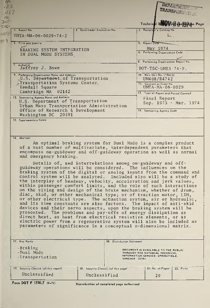
16.
Abstract
An optimal braking system for Dual Mode is a complex productof a vast number of multivariate, interdependent parameters thatencompass on-guideway and off-guideway operation as well as normaland emergency braking.
Details of, and interrelations among on-guideway and off-guideway operations will be considered. The influences on thebraking system of the digital or analog inputs from the command andcontrol system will be analyzed. Included also will be a study ofthe interplay of headway, velocity, acceleration and jerk values,within passenger comfort limits, and the role of such interactionson the sizing and design of the brake mechanism, whether of drum,disc, skid, or other mechanical type; or of traction motor, LIM,or other electrical type. The actuation system, air or hydraulic,and its time constants are also factors. The impact of anti-skiddevices and their servo aspects, upon the braking system will bepresented. The problems and pay-offs of energy dissipation asdirect heat, as heat from electrical resistive elements, or aselectric power from a regenerative system will also be included asparameters of significance in a conceptual n-dimensional matrix.
17.
Key Words
• Braking•Dual Mode• Transportation
18. Distribution Statement
DOCUMENT IS AVAILABLE TO THE PUBLICTHROUGH THE NATIONAL TECHNICALINFORMATION SERVICE. SPRINGFIELD.VIRGINIA 22151.
19. Security Classif. (of this report)
Unclassified
20. Security Classif. (of this page)
Unclassified
21» No. of Pages
29
22. Price
Form DOT F 1700.7 (8-72) Reproduction of completed page authorized

PREFACE
As a part of an overall consideration of the integration of
vehicular functions, this report studies the integration of a brak-
ing function specifically into a dual-mode transportation system,
in view of the particularities associated with such a system. The
roles of economics, safety, energy considerations and pollution are
analyzed in the establishment of the trade-offs among the factors
operative in a braking function. The interactions of the command
and control systems, the power and propulsion systems, and the
parameters of motion are reviewed in the context of the dual-mode
transportation system.
11

'
TABLE OF CONTENTS
Section Page
1. INTRODUCTION 1
2. INFLUENCES ON A BRAKING FUNCTION 4
3. OTHER CONSIDERATIONS 16
4. BRAKING IN THREE DUAL -MODE SYSTEMS 2 0
5 . SUMMARY 2 3
6. REFERENCES 2 5

LIST OF ILLUSTRATIONS
Figure Page
1. Braking System Integration in Dual Mode 3
2. Truck-Tire to Pavement Friction Coefficient (y) 5
3. Coefficient of Friction as a Function of Slip 7
4. A Typical Deceleration Curve 8
5. Typical Values of Deceleration and Jerk On-Guideway. 9
6. Interrelations Among Power and Propulsion Systemsand the Braking Systems,..., 13
7. Interrelationships Among Command and Control Systemsand the Braking Systems 15
8. Generic Schematic of Anti-Lock Systems 18
IV

1. INTRODUCTION
Dual mode transportation presents unique considerations for
subsystem choice. This paper reviews those interrelationships
of significance for integrating a braking system specifically into
a dual mode operation. Some of these relationships arise from the
interfaces of the braking system with the power and propulsion
systems and with the command and control systems. Integration of
a braking function in a dual mode system also necessitates con-
sideration of the parameters of motion; the headway, velocity, de-
celeration and jerk requirements.
The criteria against which braking systems may be measured are
those factors of safety, economics, energy management and environ-
mental impact. Foremost must be the aspect of safety to the pas-
sengers, the transit operators and the citizens of the community.
The economics of the braking system integrated into the dual mode
operation and considered as a whole must occupy a major place in the
considerations. In these days of energy shortages and crises, and
interrelated with the economic aspects, a third significant criterion
is that of energy management. This must be viewed from the operation
of the entire system. The means for converting the kinetic energy
of motion to other forms of energy, useful or unuseful, beneficial
or harmful are of significance in the total utilization of energy.
A fourth criterion of importance to a transportation system or
subsystem is its impact on the environment. Although a braking
system per se has limited environmental impact, aside from possible
pollution by friction materials and the production of unused heat,
yet the energy management aspects of braking can have a large impact
on the environment. This is then a joint function of the power and
propulsion systems and the braking system.
A dual mode transportation system involves, in general, both
an on-guideway and an off-guideway operation. The on-guideway
portions offer personal rapid transit (PRT) amenities. The require-
ments on the system, or on the vehicle in particular, in reference
to braking capabilities on the guideway are then similar to those
1

'
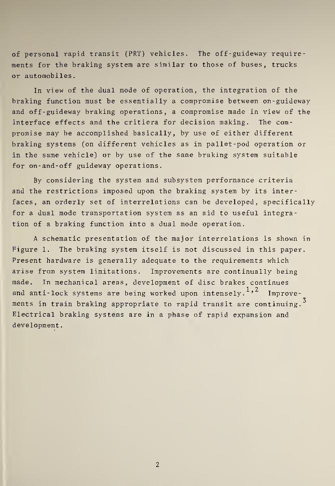
of personal rapid transit (PRT) vehicles. The off-guideway require-
ments for the braking system are similar to those of buses, trucks
or automobiles.
In view of the dual mode of operation, the integration of the
braking function must be essentially a compromise between on-guideway
and off -guideway braking operations, a compromise made in view of the
interface effects and the critiera for decision making. The com-
promise may be accomplished basically, by use of either different
braking systems (on different vehicles as in pallet-pod operation or
in the same vehicle) or by use of the same braking system suitable
for on-and-off guideway operations.
By considering the system and subsystem performance criteria
and the restrictions imposed upon the braking system by its inter-
faces, an orderly set of interrelations can be developed, specifically
for a dual mode transportation system as an aid to useful integra-
tion of a braking function into a dual mode operation.
A schematic presentation of the major interrelations is shown in
Figure 1. The braking system itself is not discussed in this paper.
Present hardware is generally adequate to the requirements which
arise from system limitations. Improvements are continually being
made. In mechanical areas, development of disc brakes continues1 2and anti-lock systems are being worked upon intensely. ’ Improve-
3ments in train braking appropriate to rapid transit are continuing.
Electrical braking systems are in a phase of rapid expansion and
development
.
2

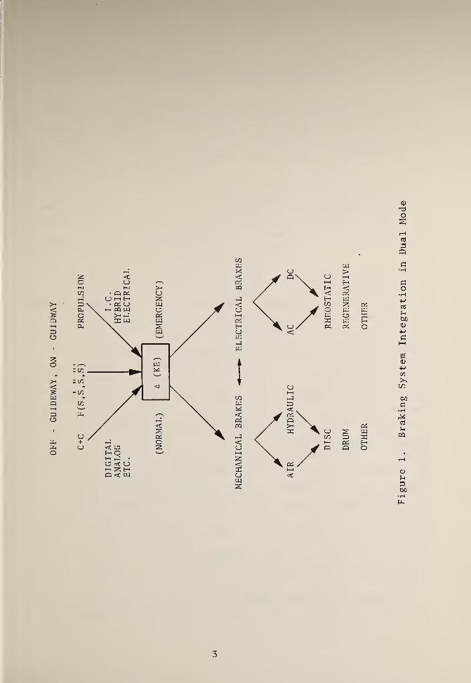
PROPULSION
3
Figure
1.
Braking
System
Integration
in
Dual
Mode

2 . INFLUENCES ON A BRAKING FUNCTION
There are many influences on the braking system as can be seen
in Figure 1. The factors which must be considered initially for the
integration of a braking function into a dual mode transportation
system are the parameters of motion, requirements of headway,
velocity, deceleration and jerk.
Control of the vehicle to suitable ranges of value of these
parameters under a variety of conditions such as gradients, wind
velocities, and temperatures are the function ultimately of the
braking system and penult imately of the command and control system.
Both may be incorporated into a braking function.
Of the four criteria discussed above, the chief concern from a
system view point in these initial considerations is that of safety,
although economic aspects related to throughput arise in connection
with headway and velocity. Jerk and deceleration limitations come6 7
from passenger safety and comfort requirements. ’ Maximum values
of . 7g deceleration with standees in the event of emergency braking
failure or .35g for emergency braking and of .15g for service braking
are imposed from safety aspects for seated and standing passengers.
Higher maxima are allowed when there are not standees in the vehicle.
In this case, the values are increased by 50%. In a similar manner
from passenger safety and comfort considerations, upper limits on
values of jerk are obtained. These are .35g/s for emergency braking
and . 15g/s for service braking, when there may be standees. When no
standees may be present in the vehicle, the maxima are raised by 50%.
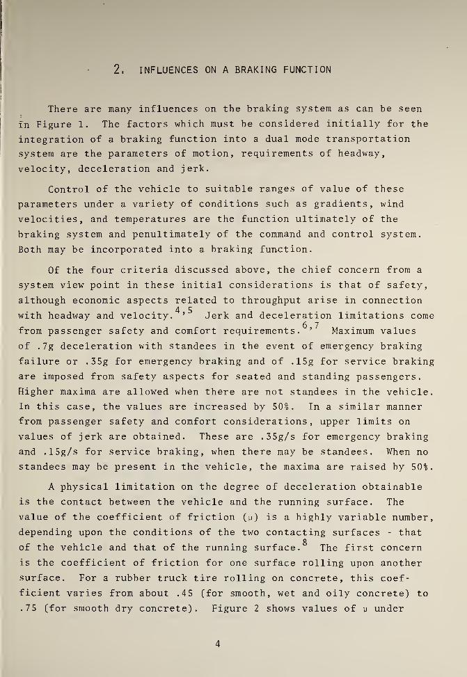
A physical limitation on the degree of deceleration obtainable
is the contact between the vehicle and the running surface. The
value of the coefficient of friction (y) is a highly variable number,
depending upon the conditions of the two contacting surfaces - thatg
of the vehicle and that of the running surface. The first concern
is the coefficient of friction for one surface rolling upon another
surface. For a rubber truck tire rolling on concrete, this coef-
ficient varies from about .45 (for smooth, wet and oily concrete) to
.75 (for smooth dry concrete). Figure 2 shows values of y under
4

:
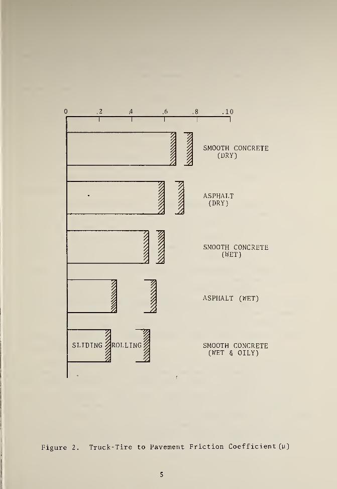
0 .2 .4 .6 .8 .10
Figure 2. Truck-Tire to Pavement Friction Coefficient (y
)
5

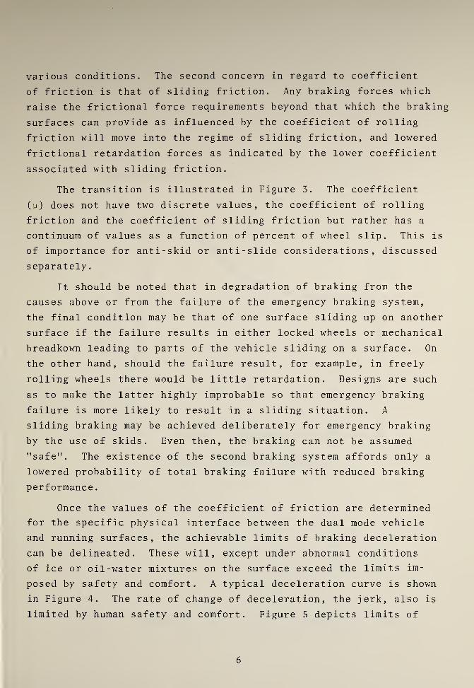
various conditions. The second concern in regard to coefficient
of friction is that of sliding friction. Any braking forces which
raise the frictional force requirements beyond that which the braking
surfaces can provide as influenced by the coefficient of rolling
friction will move into the regime of sliding friction, and lowered
frictional retardation forces as indicated by the lower coefficient
associated with sliding friction.
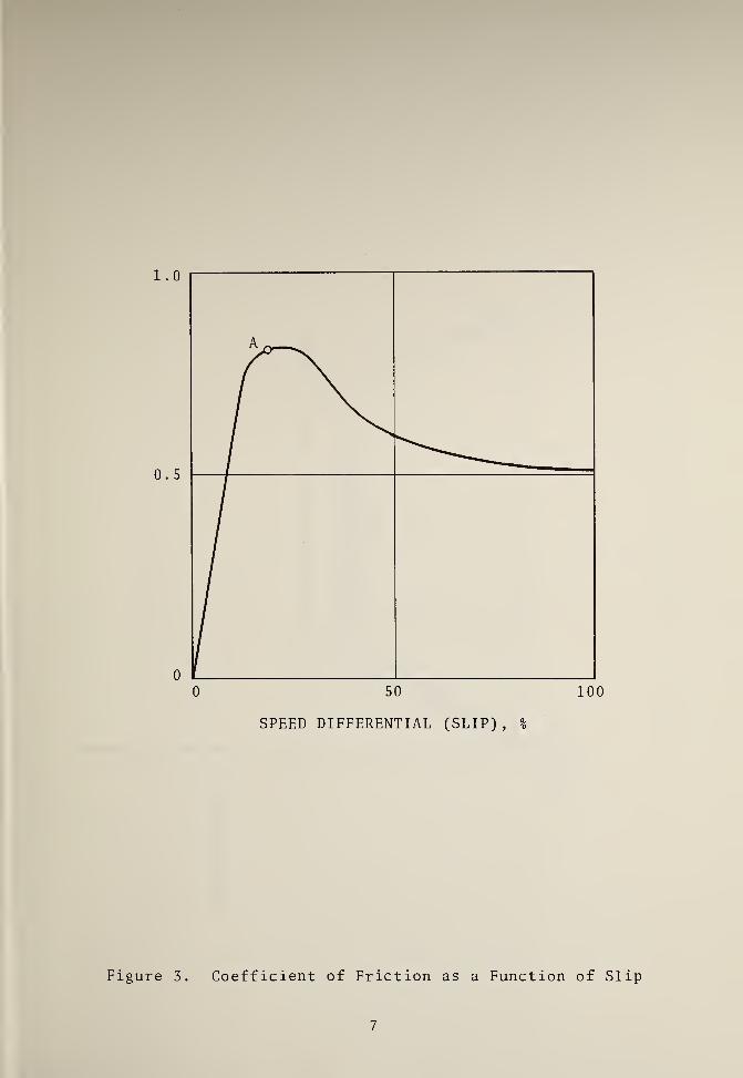
The transition is illustrated in Figure 3. The coefficient
(y) does not have two discrete values, the coefficient of rolling
friction and the coefficient of sliding friction but rather has a
continuum of values as a function of percent of wheel slip. This is
of importance for anti-skid or anti-slide considerations, discussed
separately
.
It should be noted that in degradation of braking from the
causes above or from the failure of the emergency braking system,
the final condition may be that of one surface sliding up on another
surface if the failure results in either locked wheels or mechanical
breadkown leading to parts of the vehicle sliding on a surface. On
the other hand, should the failure result, for example, in freely
rolling wheels there would be little retardation. Designs are such
as to make the latter highly improbable so that emergency braking
failure is more likely to result in a sliding situation. A
sliding braking may be achieved deliberately for emergency braking
by the use of skids. Even then, the braking can not be assumed
"safe". The existence of the second braking system affords only a
lowered probability of total braking failure with reduced braking
performance
.
Once the values of the coefficient of friction are determined
for the specific physical interface between the dual mode vehicle
and running surfaces, the achievable limits of braking deceleration
can be delineated. These will, except under abnormal conditions
of ice or oil-water mixtures on the surface exceed the limits im-
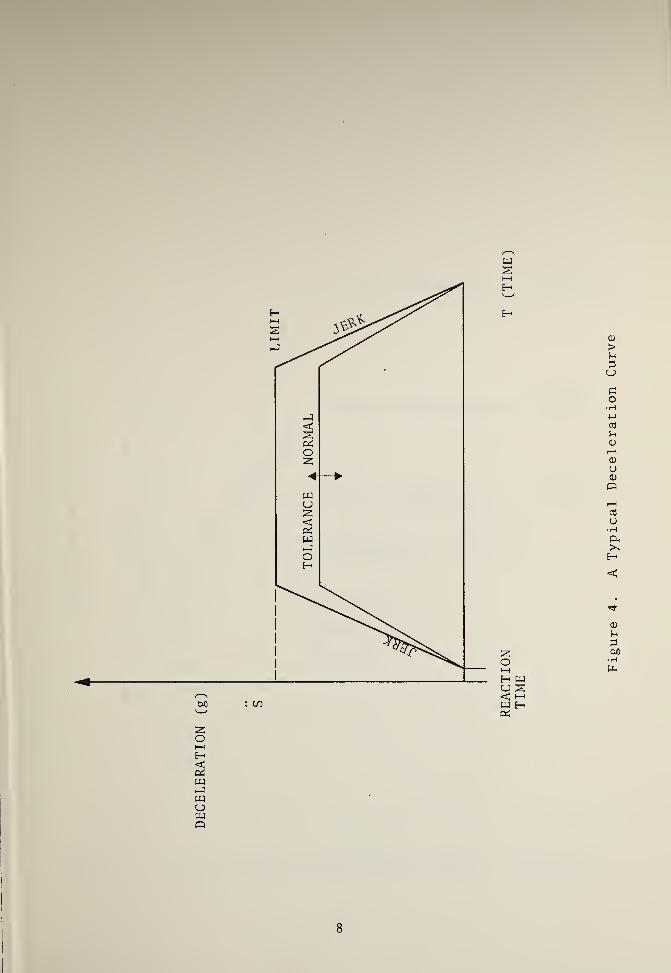
posed by safety and comfort. A typical deceleration curve is shown
in Figure 4. The rate of change of deceleration, the jerk, also is
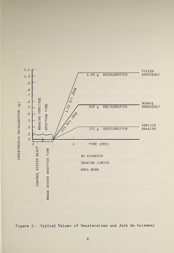
limited by human safety and comfort. Figure 5 depicts limits of
6

I
1
I
'
1.0
0 . 5
0
Figure 3 Coefficient of Friction as a Function of Slip
7

8
Figure
4.
A
Typical
Deceleration
Curve

CONTROL
SYSTEM
REACT 2H NO STANDEES22 BRAKING LIMITS
< DUAL MODEeS
FAILEDEMERGENCY
NORMALEMERGENCY
SERVICEBRAKING
wHC/3
>-C/3
W<oS
Figure 5. Typical Values of Deceleration and Jerk On-Guideway

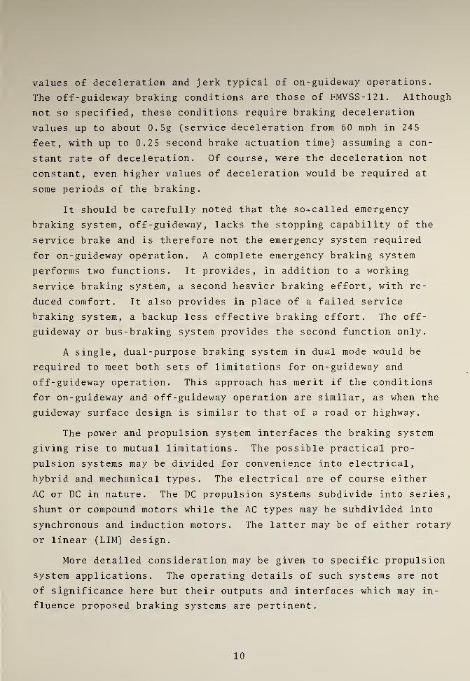
values of deceleration and jerk typical of on-guideway operations.
The off-guideway braking conditions are those of FMVSS-121. Although
not so specified, these conditions require braking deceleration
values up to about 0.5g (service deceleration from 60 mph in 245
feet, with up to 0.25 second brake actuation time) assuming a con-
stant rate of deceleration. Of course, were the deceleration not
constant, even higher values of deceleration would be required at
some periods of the braking.
It should be carefully noted that the so-called emergency
braking system, of f -guideway,lacks the stopping capability of the
service brake and is therefore not the emergency system required
for on-guideway operation. A complete emergency braking system
performs two functions. It provides, in addition to a working
service braking system, a second heavier braking effort, with re-
duced comfort. It also provides in place of a failed service
braking system, a backup less effective braking effort. The off-
guideway or bus-braking system provides the second function only.
A single, dual-purpose braking system in dual mode would be
required to meet both sets of limitations for on-guideway and
off-guideway operation. This approach has merit if the conditions
for on-guideway and off-guideway operation are similar, as when the
guideway surface design is similar to that of a road or highway.
The power and propulsion system interfaces the braking system
giving rise to mutual limitations. The possible practical pro-
pulsion systems may be divided for convenience into electrical,
hybrid and mechanical types. The electrical are of course either
AC or DC in nature. The DC propulsion systems subdivide into series,
shunt or compound motors while the AC types may be subdivided into
synchronous and induction motors. The latter may be of either rotary
or linear (LIM) design.
More detailed consideration may be given to specific propulsion
system applications. The operating details of such systems are not
of significance here but their outputs and interfaces which may in-
fluence proposed braking systems are pertinent.
10

I
The internal combustion engine as found in an automobile or
truck may, for example, be utilized as the primary power and pro-
pulsion system in a dual mode vehicle. A source of electrical
energy such as a storage battery, is required for auxilliary
functions and electronic subsystems. This may also power an
electrical secondary propulsion system.
A braking system compatible with this may be basically
mechanical with electronic controls. Braking systems of pneumatic9 10or hydraulic type are discussed in many places. ’ In order to
meet FMVSS-1, an automatic electronic anti-lock subsystem is desirable,
although not specified. This subsystem can provide, with proper de-
sign, the automatic braking required for on-guideway operations.
Anti-lock systems are considered separately in detail.
Such a braking arrangement has many merits. It is to be noted
that this study is not primarily concerned with the choice of pro-
pulsion system, but only with the compatibility of the chosen system
and the braking system and the performance of the latter. The brak-
ing system can be designed to afford the deceleration required within
the jerk limitations, provided the guideway conditions are sufficiently
good to maintain a high enough coefficient of friction. The same
system is adaptable to both on-guideway and off-guideway operations.
Brake system impact on the environment is directly limited to fric-
tion materials dissipated into the air.
Indirectly there is adverse impact on the environment from the
lack of management of the kinetic energy converted into heat, except
for such heat as is utilized either to provide warmth for the vehicles
or the stations.
Another example, a hybrid power source, is that of a mechanical-
electrical power system. Power for the electrical equipment can
either be generated on board (e.g. by a gas turbine generator) or
be collected from the wayside during the on-guideway portion of
travel. With such a hybrid power source, the brake system inter-
faces are with the electric power subsystem and the trade-off con-
siderations become essentially those of an all-electric power and
propulsion system and are a function of the type of electrical power
and propulsion systems.
11

k
To consider interface of a braking system with electrical
power and propulsion systems, two general categories are significant:
rotary and linear systems. Electric rotary motors may be used for
braking purposes in a dynamic braking system with the generated
power dumped into resistors for conversion to heat energy, but
such a conversion technique requires bulky components (the re-
sistors) which must be exposed to aid dissipation of heat and which
are thus more vulnerable to accidental failures. Such a conversion
system is useful on a large vehicle like a rapid transit car, but
is not efficient on a small vehicle because of the more severe
weight and space requirements.
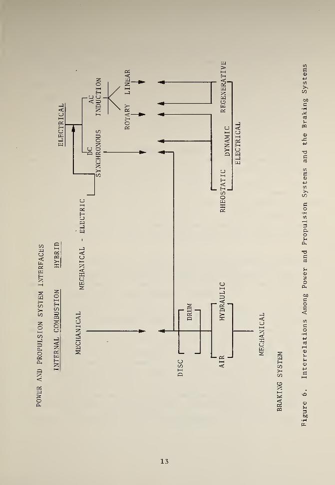
There are two manners in which electric propulsion systems may
be utilized in dual mode systems; the power generated in braking
with a rotary electric motor can be fed back into the power sources
or, in a linear motor, the motor may be "plugged", that is es-
sentially operated in reverse in a controlled way so that the vehicle
is effectively braked to a stop. The first method requires special
provisions for feeding back the power. The second method neces-
sitates careful control to bring the vehicle to a smooth and precise
stop; staying within the deceleration and jerk limits. In the case
of a linear induction motor, the service braking is essentially in-
dependent of vehicle- to-running- surface friction but rather depends
upon the electro -magnet ic interaction between the primary and the
secondary. The inter-relationships among the power and propulsion
systems and the braking system are shown in Figure 6.
The command and control systems also interface with the braking
system. Off-guideway the command and control system is the driver,
assisted by aids such as indicators, speedometers, warning lights
and control subsystems (brake boosters, anti-lock devices, etc.)
On-guideway the command and control system is an electronic system
communicating to the braking system. The electronic parts of the
braking system must be made immune to electrical interference and
should be composed of highly reliable components for safe braking
operations. A part of the control function is the monitoring aspect
in which critical component functions are automatically self-checked
and required to give status indications on a continuous or sampling
12

.
'
w>
oi<
HHPiHUwPIw
COwCJ<u-QiwE—
1
SWHCO>"CO
CO—1
3PhoPiP,
Q2:<PiPJ
o0-1
QI—
I
PiPQ
2
p<u
<2Uw
P<u
uw
H
U i-h
CO <I—
I
Q
PI<Ui—
i
2<2UWs w
HCO>-CO
CJ3
2i—
i
«2PQ
13
Figure
6.
Interrelations
Among
Power
and
Propulsion
Systems
and
the
Braking
Systems

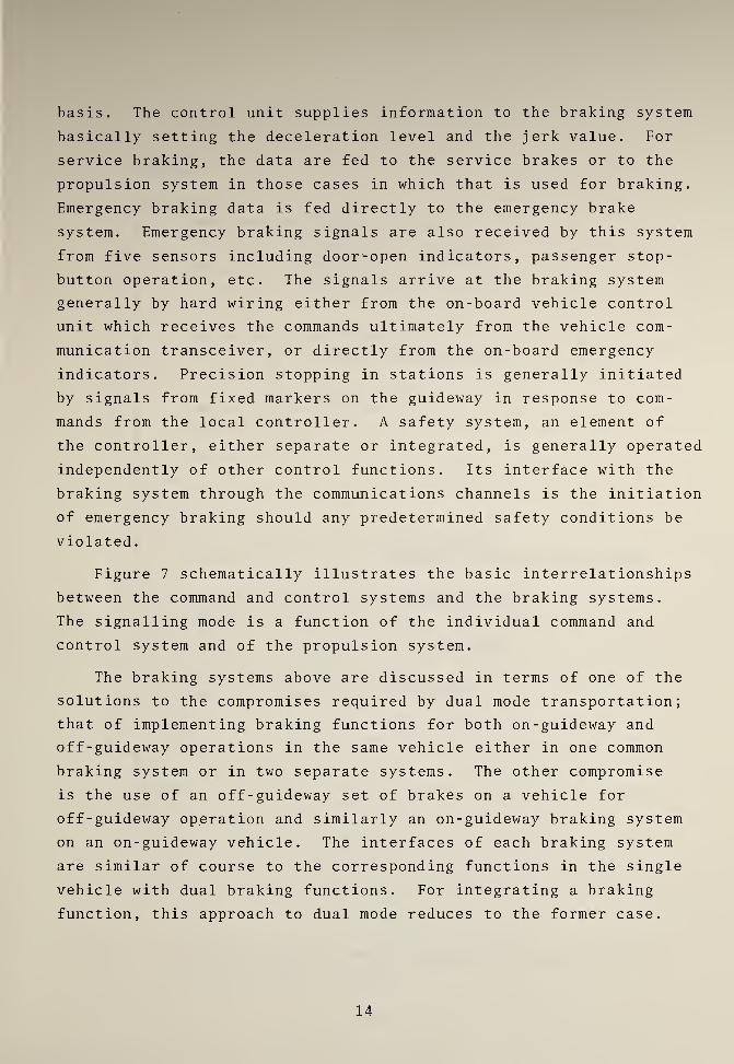
basis. The control unit supplies information to the braking system
basically setting the deceleration level and the jerk value. For
service braking, the data are fed to the service brakes or to the
propulsion system in those cases in which that is used for braking.
Emergency braking data is fed directly to the emergency brake
system. Emergency braking signals are also received by this system
from five sensors including door^-open indicators, passenger stop-
button operation, etc. The signals arrive at the braking system
generally by hard wiring either from the on-board vehicle control
unit which receives the commands ultimately from the vehicle com-
munication transceiver, or directly from the on-board emergency
indicators. Precision stopping in stations is generally initiated
by signals from fixed markers on the guideway in response to com-
mands from the local controller. A safety system, an element of
the controller, either separate or integrated, is generally operated
independently of other control functions. Its interface with the
braking system through the communications channels is the initiation
of emergency braking should any predetermined safety conditions be
violated
.
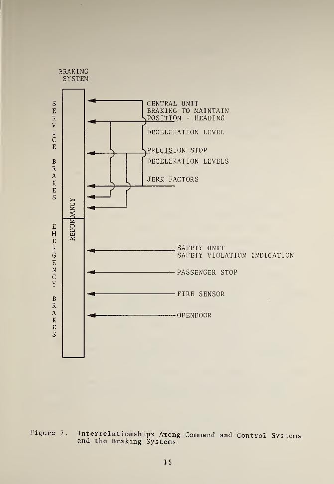
Figure 7 schematically illustrates the basic interrelationships
between the command and control systems and the braking systems.
The signalling mode is a function of the individual command and
control system and of the propulsion system.
The braking systems above are discussed in terms of one of the
solutions to the compromises required by dual mode transportation;
that of implementing braking functions for both on-guideway and
off-guideway operations in the same vehicle either in one common
braking system or in two separate systems. The other compromise
is the use of an off-guideway set of brakes on a vehicle for
off-guideway operation and similarly an on-guideway braking system
on an on-guideway vehicle. The interfaces of each braking system
are similar of course to the corresponding functions in the single
vehicle with dual braking functions. For integrating a braking
function, this approach to dual mode reduces to the former case.
14

BRAKINGSYSTEM
S
E
RVI
c
E
BRAKE
S
EME
RG
E
NC
Y
BRAKES
uz<-Q_
zowOS
CENTRAL UNITBRAKING TO MAINTAIN
pDECELERATION LEVEL
SPRECTSTON STOP
p
^
—
T~DECELERATION LEVELS
JERK FACTORS
SAFETY UNITSAFETY VIOLATION INDICATION
PASSENGER STOP
FIRE SENSOR
•OPENDOOR
Figure 7. Interrelationships Among Command and Control Systemsand the Braking Systems
15

'
3 , OTHER CONSIDERATIONS
There are some other aspects of special significance in dual
mode. The off-guideway need for an anti-lock device and the on-
guideway need for a longitudinal control system can be jointly met
by a common unit.
The necessity for reliable operation of a complex braking
function indicates the need for self-testing or monitoring of
significant subfunctions.
Operation at shorter headways requires reduction of equipment
-
reaction times and utilization of all possible means to permit safe
stopping in lessened time. The improved crashworthiness of vehicles
includes a bumper mechanism which permits contact of vehicles
without damage to the vehicles or injury to the passengers at
speeds up to some value (e.g. 5 mph) . This additional margin
must be utilized in some manner in the braking functions.
An extremely important aspect of a braking function today
is an anti-lock subsystem. ^ This is usually considered a part
of the overall braking function, but might also be conceived as
an on-board part of the control systems. Indeed the braking
function can be seen to be incorporating more and more of those
control functions previously considered separately. The incorpora-
tion of the braking controls into the braking system is all the
more necessary for transportation systems operating at higher
speeds or shorter headways. The chief function of an anti-lock
subsystem of course is the detection of an incipient skid or lock
condition in time to reduce braking force. This is accomplished
in a variety of ways which reduce basically to determining that
wheel deceleration is too high (that is, wheel speed is too slow).
The determination is made either directly by measurement of de-
celeration or indirectly by computation based on wheel speed
measurements
.
16

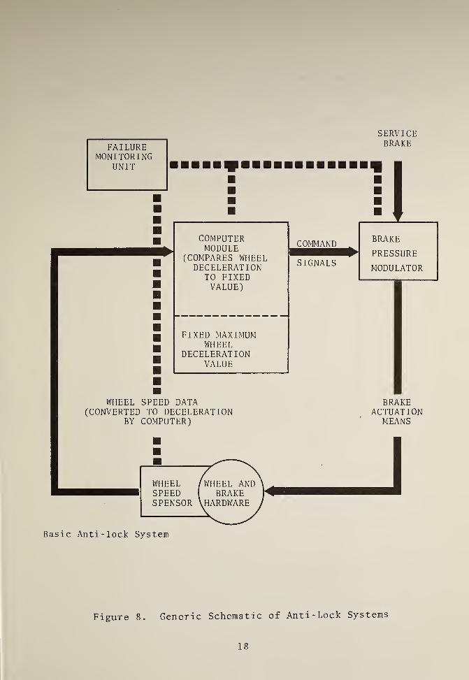
Figure 8 shows a generic schematic of an anti-lock system:
It is clear that the wheel deceleration control for anti-lock pur-
poses is also essentially that control required for automatic
operation of service braking and by extension for emergency braking.
Up-grading is of course necessary for the control system to be
adequate to the total braking requirements.
As the complexity of the braking function vastly increases,
the need for reliability and especially reliability of the electronic
components rises at least proportionally and probably at a faster
rate. Reliability must be achieved by two means simultaneously.
The one is the use -of components of higher reliability initially.
The second is the use of self-testing or monitoring of the more
significant portions of the braking furiction.
In the braking function, there are many possible test or
monitoring points. These of course vary with the specific braking
and control system.
Another factor which may be included as a part of the braking
system is that of crashworthiness. At least, those equipments
such as improved bumpers which permit controlled contacts of
vehicles up to five (5) or more miles per hour without damage to
the vehicle or danger of injury to the passengers, must be con-
sidered to provide a stopping or braking function in an emergency.
The kinetic energy of motion of a failed vehicle is in this case
transmitted to the leading vehicle or at least to its bumper
mechanism. The controlled contact should be included in braking
considerations for back-up to a failed emergency stopping system
and as a tolerance factor in normal emergency stopping. This can
lead to economies in both the braking function itself and the dual
mode system overall.
Fail-safe concepts and misconcepts constitute another area
for serious consideration for integration of a braking function
into dual model transportation. At the most, the fail-safe concept
implies the detection of a failure of one mode (of braking, in this
case) will institute a backup mode which in general have a lower
probability of failure. The combination of braking modes will have
17

FAILUREMONITORING
UNIT
SERVICEBRAKE
COMPUTERMODULE
(COMPARES WHEELDECELERATION
TO FIXEDVALUE)
COMMANI)
SIGNALS
FIXED MAXIMUMWHEEL
DECELERATIONVALUE
BRAKE
PRESSURE
MODULATOR
WHEEL SPEED DATA(CONVERTED TO DECELERATION
BY COMPUTER)
BRAKEACTUATION
MEANS
Basic Anti-lock System
Figure 8. Generic Schematic of Anti-Lock Systems
18

a lower probability of failure. The fail-safe concept as tradi-
tionally understood since its inception in the 1880's implies a re-
version "to a state which is known to be safe." The National
Transportation Safety Board recommends abandonment of the fail-safe1
2
concept and the institution of an organized disciplined approach.
Fault tree analysis is suggested as an alternative. Fault tree
analysis considers the impact of single failures and multiple
failures in a graphic presentation which isolates the truly critical
components
.
19

L\. BRAKING IN THREE DUAL-MODE SYSTEMS
Thus far, we have reviewed the criteria and the significant
interrelationships which influence the considerations for inter-
grating a brake function into a dual mode transit system. An
application, of rather general nature, of these principles will
be made to three dual mode systems: those of TTI, Rohr and GMC
.
The TTI system is that of a pallet-pod operation. On-guideway
a "Transporter" is used. Two single sided linear induction motors
C L IM) provide the propulsion. Fourteen HOVAIR air cushion pads
support the on-guideway vehicle. The emergency braking is pro-
vided by brake skids, and normal braking by LIM plugging. Off-
guideway, a close- to-standard van is used, with standard bus
braking. A Mercedes Benz 0309D passenger bus is presently the
choice. (Incidently, the Mercedes Benz 0307 overland bus has re-
cently been awarded the Grand Prix Louis Bolandard in tests12ranging from seating comfort to driving precision.
The Rohr system utilizes one vehicle for on-and-off guideway.
Off-guideway the power and propulsion system consists of a gas
turbine operation in an electric system composed of an alternator,
rectifier, inverter and three phase rotary induction motor. On-
guideway, the power is received from way-side. Braking is achieved
by airpowered dual wedge drum type brakes (like Transbus) and has
anti-skid control meeting FMVSS121. The anti-skid control, up-
graded, is used for automatic electronic control on-guideway.
The General Motors dual mode system utilizes, essentially, a
GMC Motor Home on-and-off -guideway . Braking is provided by two2
disc front brakes and two drum rear brakes which provide 244cm
of braking area in the rear. The vehicle is provided with a dual
split master cylinder which is vacuum boosted.
The primary braking system incorporates four hydraulic-actuated
multi-disc brakes located on the front driving axle as an integral
part of the electric motor assembly. The master cylinder is split
for a dual system and has an electric power assist to minimize
braking effort requirements.
20

The vehicle will be equipped with anti-lock braking control to
meet FMVSS105. Major components of the system are speed sensors
mounted on the wheels, brake pressure control valves, and control
circuitry integrated into the electronic control system equipment.
Emergency braking capability is provided in two ways. The
dual application system reduces the probability of a complete loss
of primary brakes. Secondly, when a loss of application pressure
is sensed in either side of the system, the secondary propulsion
electric drive motors will be energized, generating reverse torque.
The resultant drag assists in decelerating the vehicle.
The primary braking system and the emergency braking system
will be continuously monitored and controlled while the vehicle
is operating in the automatic mode on the guideway.
The Longitudinal Control System includes the employment of
an accelerometer to help provide smooth service braking and
emergency braking through coordinated throttle and brake actuators.
The parking brake is actuated through a conventional lever
which applies the pressure pods on the disc front and intermediate
axle brakes.
With this brief review of the chief characteristics of the
braking system and their interfacing systems, some aspects of the
integration may now be considered. The braking systems, summarized
are
:
1) LIM braking and skids; standard bus,
2) Drum,
3) Disc and drum.
It is clear that the latter two are not very esoteric. They
are nevertheless adequate to the task. A bus driver can control
these with precision. The possible problems with such braking
systems are then in the automatic control section. It should be
carefully noted that the more severe limitations of FMVSS-121 is
on the service braking (not on the "emergency" braking.) On-
guideway the emergency braking must control the design. These
differences should be reconciled by making the emergency braking
21

sufficient for the on-guideway travel; it will then exceed the re-
quirements of FMVSS-121, and indeed should do so. As another con-
sideration, it should be noted that care should be given to ascer-
taining that precision stopping (e.g. in stations) will be achieved
with the automatic control system in conjunction with the latter
two braking systems.
The first dual-mode system, off-guideway utilizes a standard
braking system which should meet FMVSS-121. On-guideway if reverse
thrust is inadequate to the slowing or stopping requirement, the
pallet-pod is lowered to permit skid braking. Care must be ex-
ercised that a sufficiently safe system is worked out for such an
event. Lift by air cushion pods must be positively cut-off, and
adequate safeguards for quick detection of lack of plugging of
the LIM installed. Consideration must be given to the skid
design such that proper emergency braking will be achieved. Should
the skids land unevenly, or should the frictional coefficients
between the running surface and the skid vary from part to part,
lateral or tumbling forces could result.
In terms of the general concepts of integration of a braking
system into a dual-mode vehicle, each of the dual-mode vehicles
incorporates a braking system which meets its interfaces well
(and each meets a different set of interfaces) . Judgements must
then be made, not on the individual braking system, but on the
overall complex of power and propulsion systems, command and
control systems and braking systems.
22

5 , SUMMARY
There are many interrelationships of significance for properly
integrating a braking function specifically into a dual mode trans-
portation system.
Factors shaping the characteristics of the braking system are
its interfaces with other vehicle systems. The braking system must
be compatible with the power and propulsion systems and with the
command and control functions. The operational parameters of
motion the headway, velocity, deceleration and jerk limits con-
stitute, of course, another set of determining factors.
A dual mode transportation system involves, in general,
both an on-guideway and an off-guideway operation. The on-guideway
portion offers essentially personal rapid transit amenities. The
requirements in the vehicle in reference to braking capabilities
on the guideway are then similar to those of personal rapid transit
(PRT) vehicles. The off -guideway braking system requirements are
similar to those of buses, trucks or automobiles. The integration
of a braking function into a dual mode system must be basically
a compromise among on-guideway and off-guideway braking operations.
In general, the compromise may be accomplished by use of either
different braking systems (on different vehicles as in a pallet-pod
operation, or in the same vehicle) or by use of the same braking
system suitable for on-and-off guideway operations.
Criteria against which braking systems may be measured are
those factors of safety, economics, energy management and environ-
mental impact. By considering these criteria, and the limitations
set by the braking system's interfaces, an organized set of matrix
of interrelations is developed, from which desirable and undesirable
aspects of integration of braking functions into a dual mode system
can be determined.
The significance of the interfaces is such that these become
the controlling factors. The actual braking hardware now available,
with proper design and application, is adequate for tasks of stop-
ping dual mode vehicles. The braking function of necessity includes
23


its controls, especially as headway is lowered to tenths of
seconds on-guideway, where the limitations are the more restrictive.
Of f- guideway ,service braking is the more restrictive, and
"emergency" braking can be considered as back-up braking. Fail-
safe braking is possible only when all interrelationships are
properly evaluated. Fail-safe, here and in general, can mean
only that under a failed mode, the function is put into a back-up
mode with reduced probability of failure.
A safety analysis such as fault-tree analysis is preferable to
reliance on fail-safe concepts.
24

6,
REFERENCES
1. G. Dike, On Optimum Design of Disc Brakes, American Society
of Mechanical Engineers, Design Engineering Division, 1973.
2. V.T. Nicolas etal, Simulation of Control Schemes for
Anti-skid Brake Systems , American Society of Mechanical
Engineers, Intersociety Committee on Transportation, 1973.
3. G.M. Cabbie et al, Disc Assist, the Simultaneous Use of
Tread and Disc Brakes,American Society of Mechanical Engineers,
Rail Transportation Division, 1973.
4. Urban Mass Transportation Administration, High Capacity Personal
Rapid Transit Systems Developments,Office of Research and
Development, Washington, DC, 1973.
5. J.E. Anderson et al., Personal Rapid Transit, Institute of
Technology, University of Minnesota, 1972. p 207 ff.
6. American National Standards Institute Guide for the Evaluation
of Human Exposure of Whole-Body Vibration , ISO/TC 108,
Mechanical Vibrations and Shock, NY.
7. J.W Gebhard, Acceleration and Comfort in Public Ground Trans -
portation,The Johns Hopkins University, APL. Maryland, 1970.
8. L.A. Hoel et al. ,
Urban Rapid Transit Concepts and Evaluation
Transportation Research Institute,Carnegie-Mellon University,
Pittsburgh, PA 1968.
9. J.J. Bowe, Assessment of Freight Train Braking Systems,
Department of Transportation, Transportation Systems Center,
Cambridge, MA. To be published, 1974.
10. Newcombe and Spurr ,Automobile Brakes and Braking Systems
,
R. Bentley, Inc., 1960
11. J.E. Anderson et al., Personal Rapid Transit, Institute of
Technology
,
12. Metropolitan, August 1973, pg. 4
25