Embed Size (px)
Citation preview
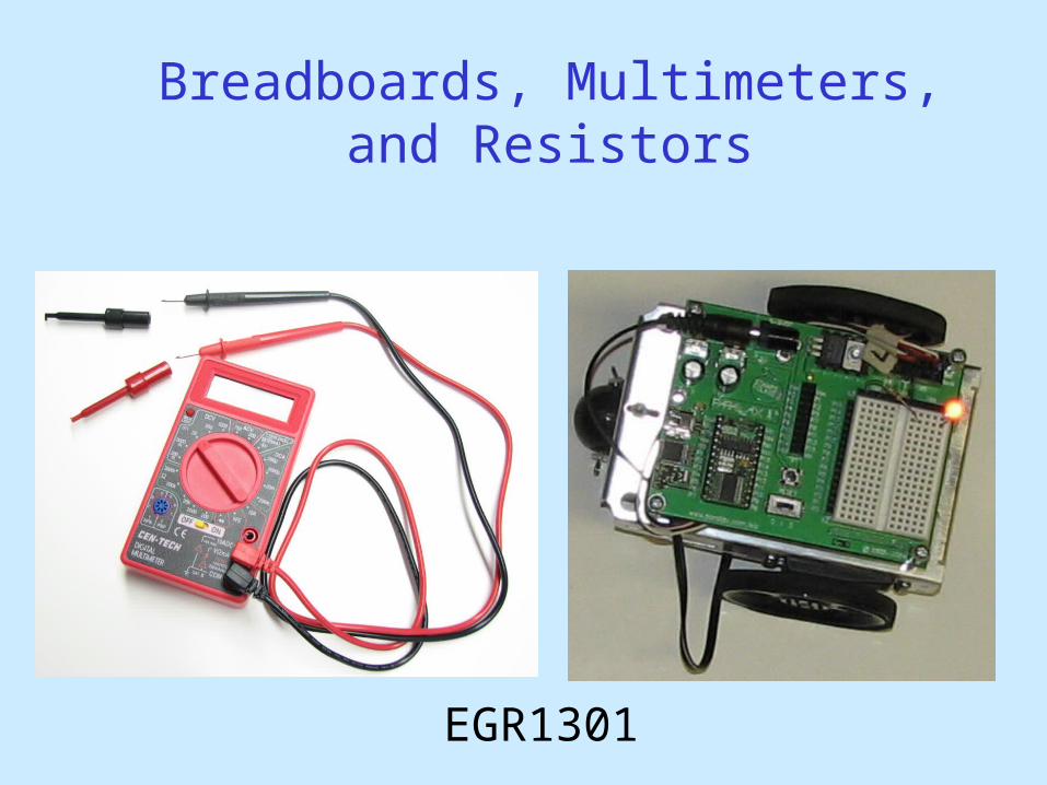
Breadboards, Multimeters, and Resistors
EGR1301

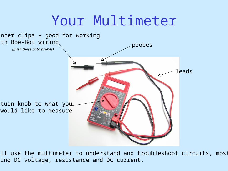
Your Multimeter
leads
probes
pincer clips – good for workingwith Boe-Bot wiring
You will use the multimeter to understand and troubleshoot circuits, mostlymeasuring DC voltage, resistance and DC current.
turn knob to what youwould like to measure
(push these onto probes)
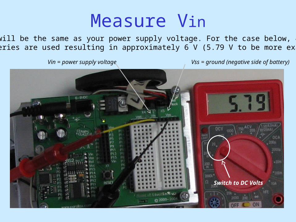
Measure VinVin will be the same as your power supply voltage. For the case below, 4 AAbatteries are used resulting in approximately 6 V (5.79 V to be more exact).
Vin = power supply voltage Vss = ground (negative side of battery)
Switch to DC Volts
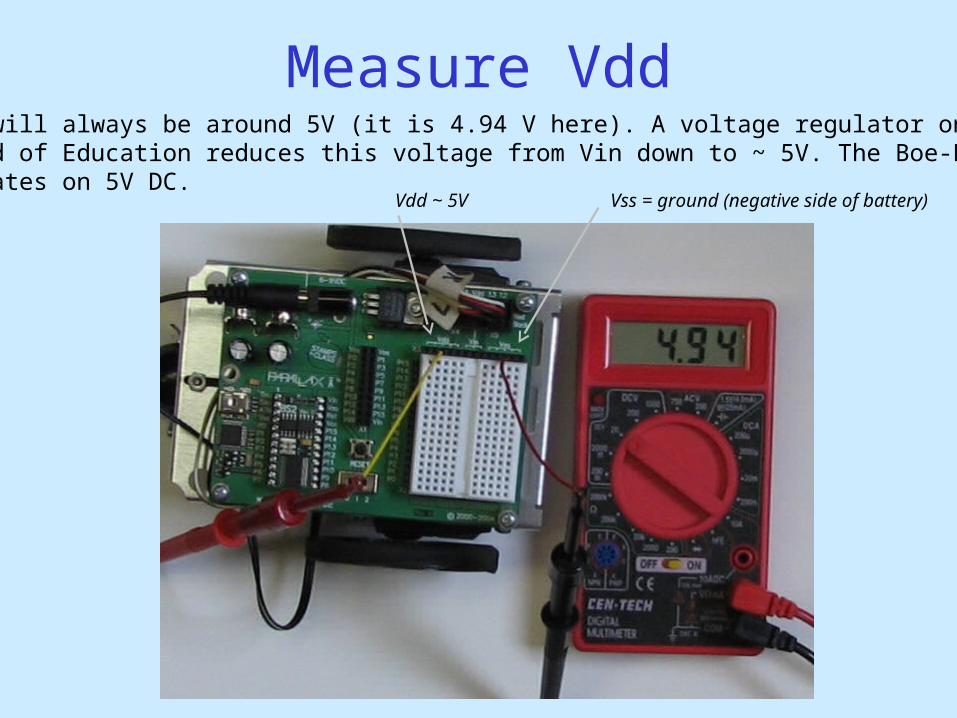
Measure VddVdd will always be around 5V (it is 4.94 V here). A voltage regulator on the Board of Education reduces this voltage from Vin down to ~ 5V. The Boe-Bot operates on 5V DC.
Vdd ~ 5V Vss = ground (negative side of battery)
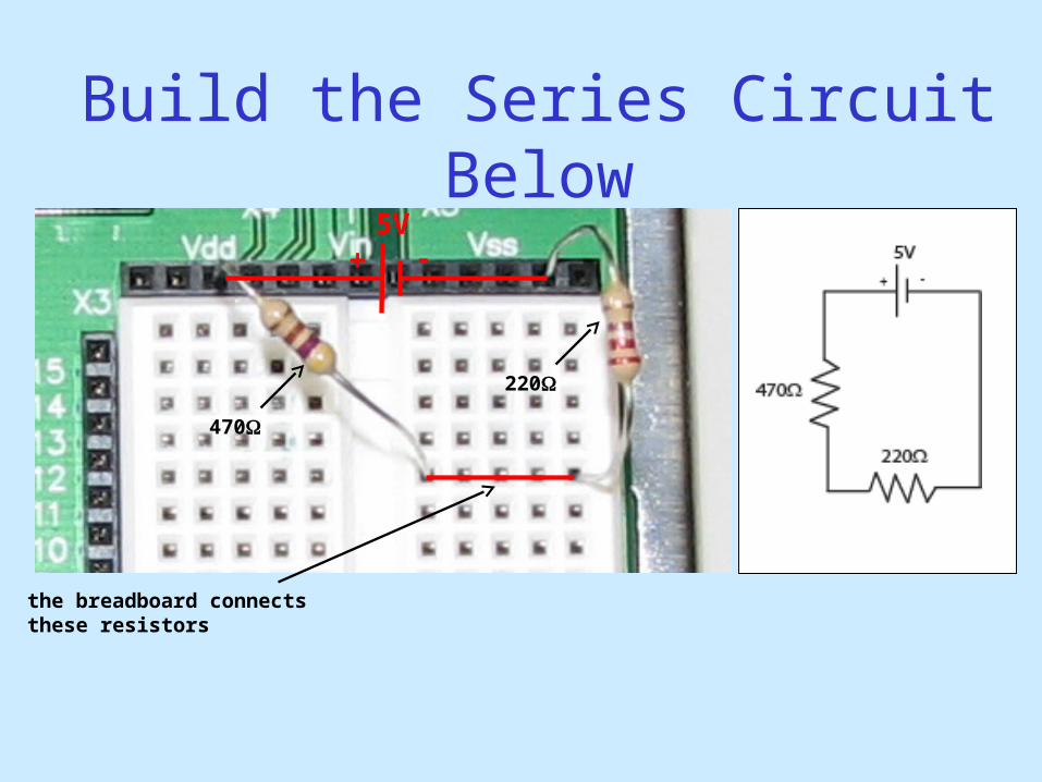
Build the Series Circuit Below
470
220
the breadboard connectsthese resistors
5V
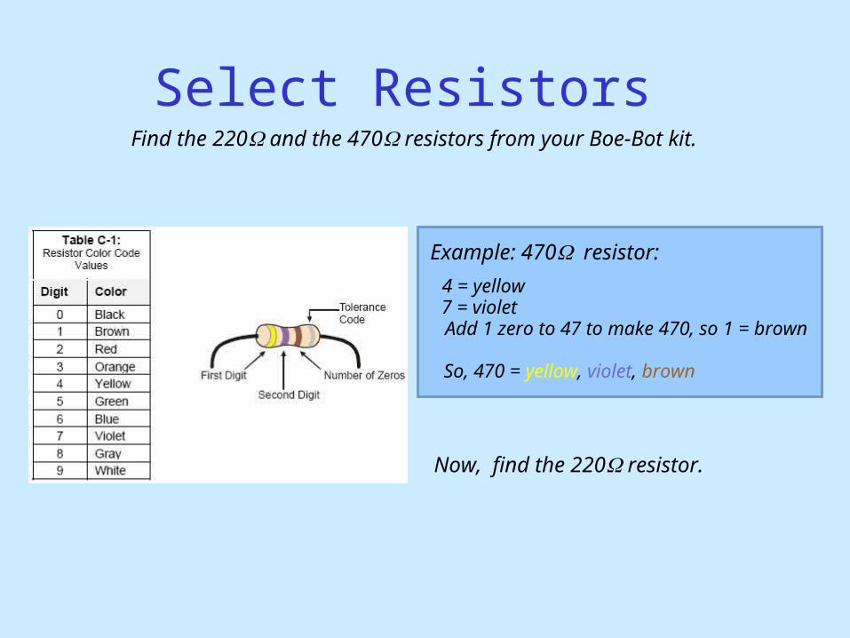
Select Resistors Find the 220 and the 470 resistors from your Boe-Bot kit.
Example: 470resistor:
4 = yellow7 = violetAdd 1 zero to 47 to make 470, so 1 = brown
Now, find the 220 resistor.
So, 470 = yellow, violet, brown
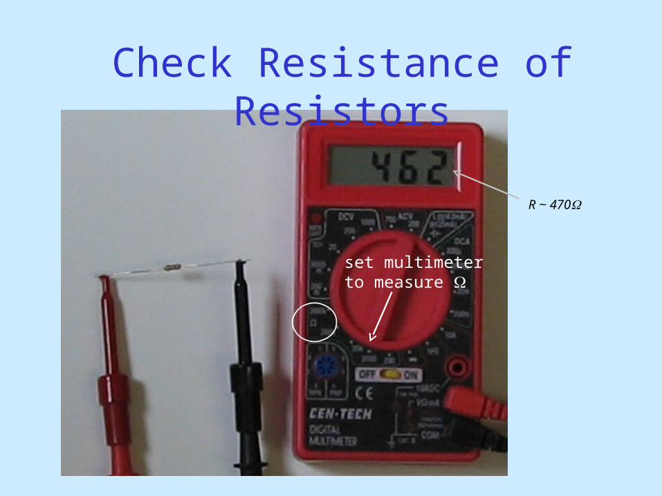
set multimeterto measure
R ~ 470
Check Resistance of Resistors
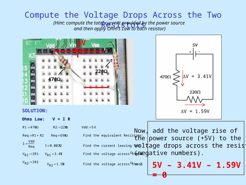
Compute the Voltage Drops Across the Two Resistors
Ohms Law: V = I R
R1 470 R2 220 Vdd 5 V
Req R1 R2 Req 690 Find the equivalent Resistance
IVdd
Req
I 0.0072A Find the current leaving Vdd
VR1 I R1 VR1 3.41V Find the voltage across the 470 resistor
VR2 I R2VR2 1.59V Find the voltage across the 220 resistor
V = 3.41V
V = 1.59V
470
220
5V
(Hint: compute the total current provided by the power source and then apply Ohm’s Law to each resistor)
5V – 3.41V – 1.59V = 0
Now, add the voltage rise of the power source (+5V) to the voltage drops across the resistors(negative numbers).
SOLUTION:
Your Multimeter
leads
probes
pincer clips – good for workingwith Boe-Bot wiring
You will use the multimeter to understand and troubleshoot circuits, mostlymeasuring DC voltage, resistance and DC current.
turn knob to what youwould like to measure
(push these onto probes)
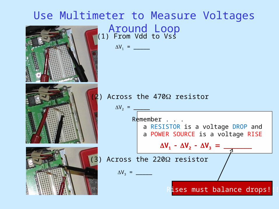
Use Multimeter to Measure Voltages Around Loop
(1) From Vdd to Vss
(2) Across the 470 resistor
(3) Across the 220 resistor
Remember . . . a RESISTOR is a voltage DROP and a POWER SOURCE is a voltage RISE
V1 = _____
V2 = _____
V3 = _____
V1V2V3
Rises must balance drops!!!!
V = 3.41V
V = 1.59V
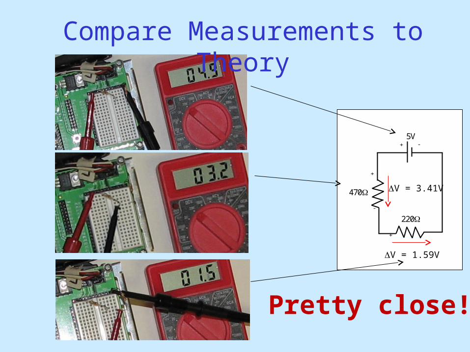
Compare Measurements to Theory
5V
+ -
470
220
+
+
-
Pretty close!
V = 3.41V
V = 1.59V
5V – 3.41V – 1.59V = 0
5V
+ -
470
220
+
+
-
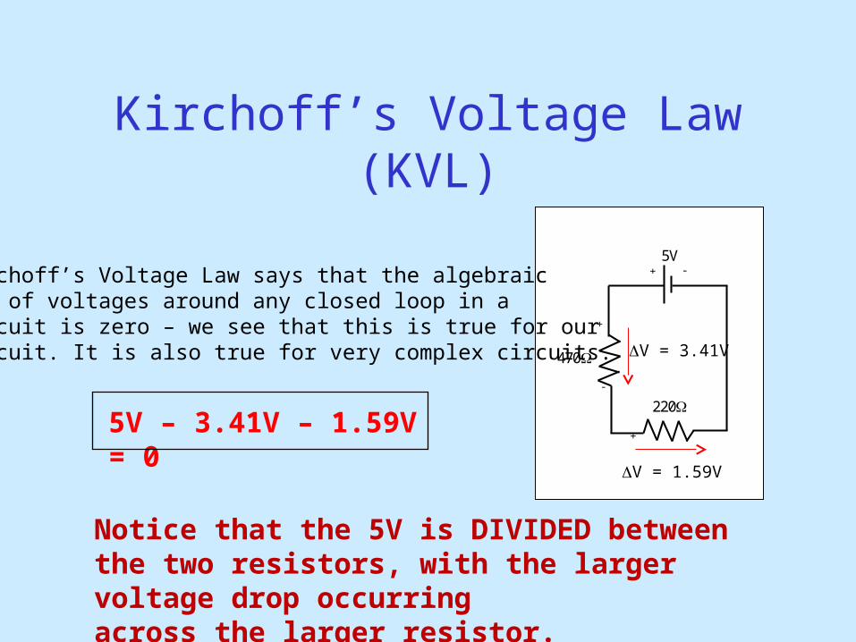
Kirchoff’s Voltage Law (KVL)
Kirchoff’s Voltage Law says that the algebraicsum of voltages around any closed loop in a circuit is zero – we see that this is true for ourcircuit. It is also true for very complex circuits.
Notice that the 5V is DIVIDED between the two resistors, with the larger voltage drop occurring across the larger resistor.
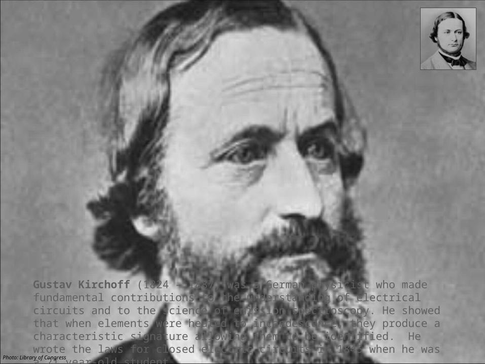
Gustav Kirchoff (1824 – 1887) was a German physicist who made fundamental contributions to the understanding of electrical circuits and to the science of emission spectroscopy. He showed that when elements were heated to incandescence, they produce a characteristic signature allowing them to be identified. He wrote the laws for closed electric circuits in 1845 when he was a 21 year-old student.
Photo: Library of Congress
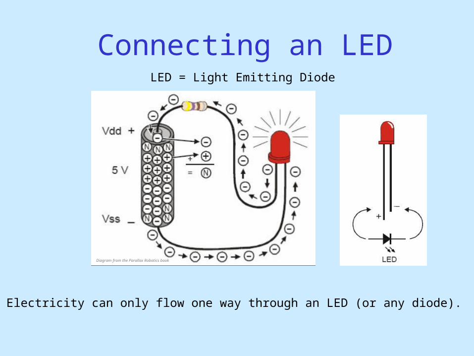
Connecting an LED
Electricity can only flow one way through an LED (or any diode).
LED = Light Emitting Diode
Diagram from the Parallax Robotics book
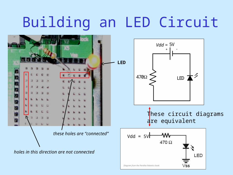
Building an LED Circuit
Vdd = 5V
LED
5V
+ -
470
These circuit diagramsare equivalent
these holes are “connected”
Vdd =
LED
holes in this direction are not connected
Diagram from the Parallax Robotics book
Replace the 470 Resistor with the 10k Resistor
What happens and Why??
ANSWER: The smaller resistor (470) provides less resistance to current thanthe larger resistor (10k). Since more current passes through the smallerresistor, more current also passes through the LED making it brighter.
What would happen if you forgot to put in a resistor? You would probably burn up your LED.