Embed Size (px)
Citation preview

BRE/TSLAB – VulcanComparisons
Roger Plank
Anthony Abu & Ian Burgess
25-Sep-07 © The University of Sheffield - Structural Fire Engineering Group
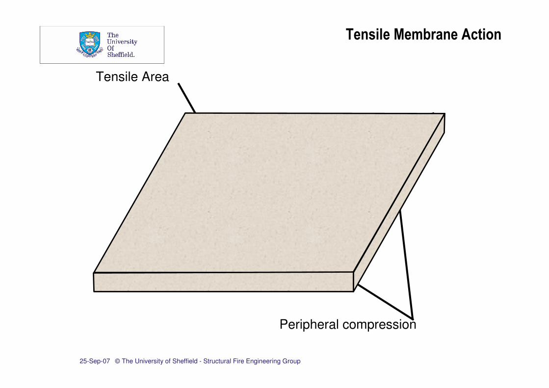
Tensile Membrane Action
Peripheral compression
Tensile Area

25-Sep-07 © The University of Sheffield - Structural Fire Engineering Group
• Rigid – plastic theory with large change of geometry
• Yield line capacity
• Membrane enhancement to yield line capacity
• Panels are horizontally unrestrained
• Vertical support at the boundaries
• Tensile strength of concrete is ignored
BRE – Bailey Method

25-Sep-07 © The University of Sheffield - Structural Fire Engineering Group
φ
nL
L
l
SS
BRE – Bailey Method
T1
T2
T2’ T2
’
T2
C C
T2 T2
T1
CC
25-Sep-07 © The University of Sheffield - Structural Fire Engineering Group
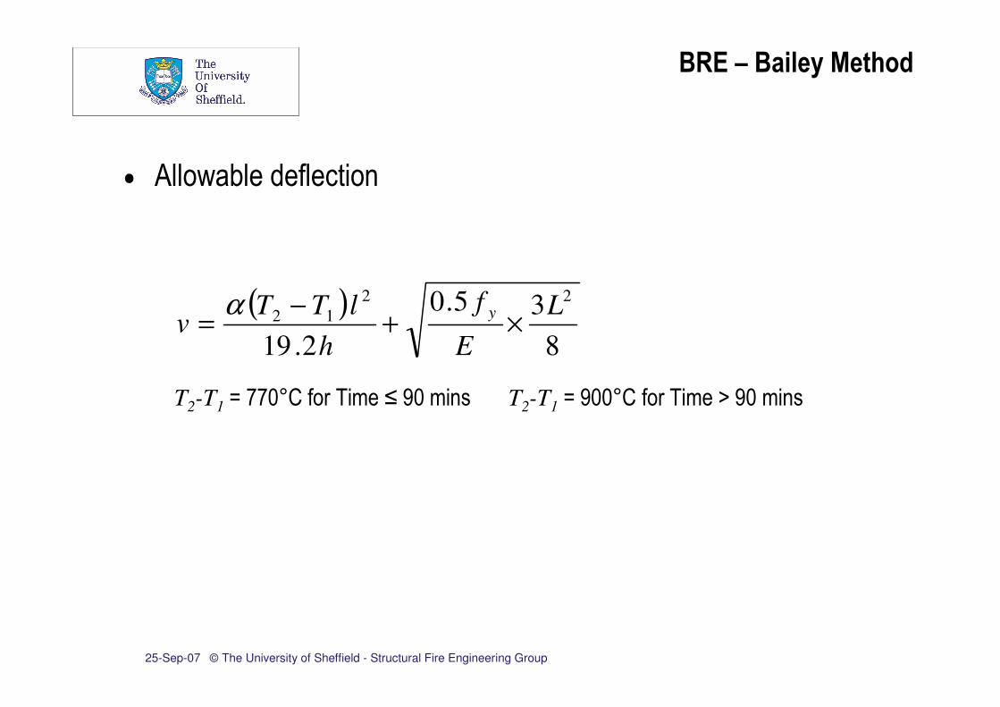
• Allowable deflection
( )
8
35.0
2.19
22
12L
E
f
h
lTTv
y×+
−=
α
T2-T1 = 770°C for Time ≤ 90 mins T2-T1 = 900°C for Time > 90 mins
BRE – Bailey Method

25-Sep-07 © The University of Sheffield - Structural Fire Engineering Group
• Do protected beams provide adequate vertical support?
• Effect of reinforcement ratios on failure
• Effect of tensile strength of concrete
• Effect of edge continuity
Comparison between Vulcan and
BRE – Bailey Method

25-Sep-07 © The University of Sheffield - Structural Fire Engineering Group
• 9.0m x 6.0m, 7.5m x 9.0m, 9.0m x 9.0m, 9.0m x 12.0m
• S275 beams
• Trapezoidal deck profile
• Normal weight concrete
• Strength (fcu = 40N/mm2, fck = 35N/mm2)
• S500 Reinforcement mesh
• Average mesh position (from top surface) = 45mm
Slab-Panel Properties

25-Sep-07 © The University of Sheffield - Structural Fire Engineering Group
Slab-Panel Properties
25-Sep-07 © The University of Sheffield - Structural Fire Engineering Group
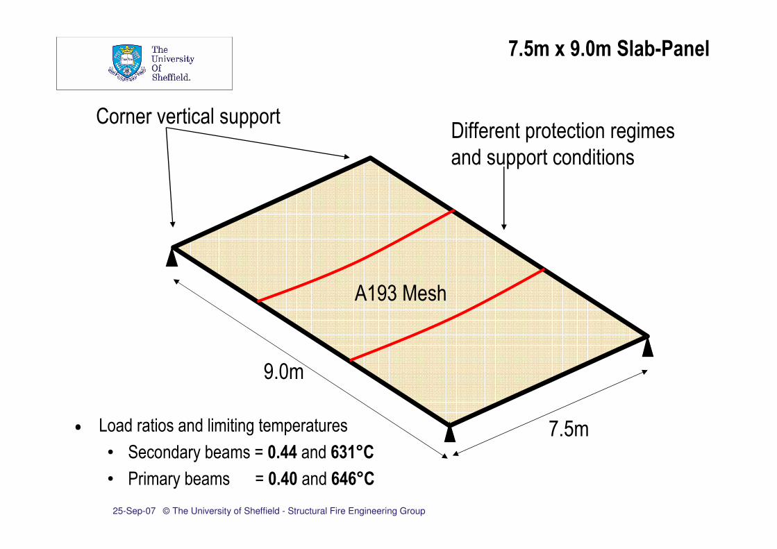
7.5m x 9.0m Slab-Panel
9.0m
7.5m
Corner vertical supportDifferent protection regimes
and support conditions
A193 Mesh
• Load ratios and limiting temperatures
• Secondary beams = 0.44 and 631°C
• Primary beams = 0.40 and 646°C

25-Sep-07 © The University of Sheffield - Structural Fire Engineering Group
-1000
-900
-800
-700
-600
-500
-400
-300
-200
-100
0
0 10 20 30 40 50 60 70 80 90
Time (min)
Vertical Displacement (mm)60 mins
Span/20
( )8
35.0
2.19
77022
L
E
f
h
lCv
y×+=
oαBRE Limit
( )
8
35.0
2.19
22
12L
E
f
h
lTTv
y×+
−=
αTSLAB
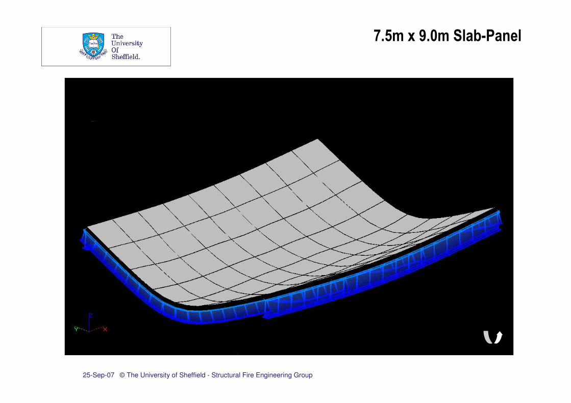
7.5m x 9.0m Slab-Panel

25-Sep-07 © The University of Sheffield - Structural Fire Engineering Group
-1000
-900
-800
-700
-600
-500
-400
-300
-200
-100
0
0 10 20 30 40 50 60 70 80 90
Time (min)
Vertical Displacement (mm)
7.5m x 9.0m Slab-Panel
Bailey - BRE Method

25-Sep-07 © The University of Sheffield - Structural Fire Engineering Group
7.5m x 9.0m Slab-Panel

25-Sep-07 © The University of Sheffield - Structural Fire Engineering Group
7.5m x 9.0m Slab-Panel

25-Sep-07 © The University of Sheffield - Structural Fire Engineering Group
7.5m x 9.0m Slab-Panel

25-Sep-07 © The University of Sheffield - Structural Fire Engineering Group
7.5m x 9.0m Slab-Panel

25-Sep-07 © The University of Sheffield - Structural Fire Engineering Group
7.5m x 9.0m Slab-Panel

25-Sep-07 © The University of Sheffield - Structural Fire Engineering Group
7.5m x 9.0m Slab-Panel

25-Sep-07 © The University of Sheffield - Structural Fire Engineering Group
7.5m x 9.0m Slab-Panel

25-Sep-07 © The University of Sheffield - Structural Fire Engineering Group
7.5m x 9.0m Slab-Panel
25-Sep-07 © The University of Sheffield - Structural Fire Engineering Group
7.5m x 9.0m Slab-Panel

25-Sep-07 © The University of Sheffield - Structural Fire Engineering Group
-1000
-900
-800
-700
-600
-500
-400
-300
-200
-100
0
0 10 20 30 40 50 60 70 80 90
Time (min)
Vertical Displacement (mm)
7.5m x 9.0m Slab-Panel
Vulcan – edge support
Vulcan – corner support
– Generic Protection

25-Sep-07 © The University of Sheffield - Structural Fire Engineering Group
-1000
-900
-800
-700
-600
-500
-400
-300
-200
-100
0
0 10 20 30 40 50 60 70 80 90
Time (min)
Vertical Displacement (mm)
7.5m x 9.0m Slab-Panel
Vulcan – Displacement of slab panel
centre relative to secondary beam
Vulcan – Displacement of slab panel
centre relative to primary beam

25-Sep-07 © The University of Sheffield - Structural Fire Engineering Group
-1000
-900
-800
-700
-600
-500
-400
-300
-200
-100
0
0 10 20 30 40 50 60 70 80 90
Time (min)
Vertical Displacement (mm)
7.5m x 9.0m Slab-Panel

25-Sep-07 © The University of Sheffield - Structural Fire Engineering Group
-1000
-900
-800
-700
-600
-500
-400
-300
-200
-100
0
0 10 20 30 40 50 60 70 80 90
Time (min)
Vertical Displacement (mm)
Vulcan – Cold Perimeter Beams – Edge
support - Tensile strength of concrete
included
Vulcan – Cold Perimeter Beams –
Edge support - Tensile strength of
concrete ignored
7.5m x 9.0m Slab-Panel

25-Sep-07 © The University of Sheffield - Structural Fire Engineering Group
• Maximum absolute vertical displacements
• Deflection plots (mesh sizes)
• A142 – Navy blue
• A193 – Red
• A252 – Green
• A393 - Black
• Analytical approaches
• BRE Method – Solid lines
• Vulcan – Broken lines
Main Study
25-Sep-07 © The University of Sheffield - Structural Fire Engineering Group
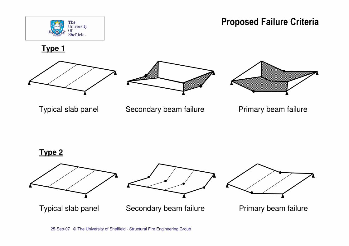
Typical slab panel Secondary beam failure Primary beam failure
Type 1
Typical slab panel Secondary beam failure Primary beam failure
Type 2
Proposed Failure Criteria

25-Sep-07 © The University of Sheffield - Structural Fire Engineering Group
-1000
-900
-800
-700
-600
-500
-400
-300
-200
-100
0
0 10 20 30 40 50 60 70 80 90
Time (min)
Maxim
um
Dis
pla
cem
ent
(mm
)
Vulcan Results
-1000
-900
-800
-700
-600
-500
-400
-300
-200
-100
0
0 10 20 30 40 50 60 70 80 90
Time (min)M
axim
um
Dis
pla
cem
ent
(mm
)
Plastic Failure
9.0m x 6.0m Slab-Panel
Type 2
Type 1

25-Sep-07 © The University of Sheffield - Structural Fire Engineering Group
-1000
-900
-800
-700
-600
-500
-400
-300
-200
-100
0
0 10 20 30 40 50 60 70 80 90
Time (min)
Maxim
um
Dis
pla
cem
ent
(mm
)
Vulcan Results
-1000
-900
-800
-700
-600
-500
-400
-300
-200
-100
0
0 10 20 30 40 50 60 70 80 90
Time (min)M
axim
um
Dis
pla
cem
ent
(mm
)
Plastic Failure
9.0m x 12.0m Slab-Panel
Type 2
Type 1

25-Sep-07 © The University of Sheffield - Structural Fire Engineering Group
-1000
-900
-800
-700
-600
-500
-400
-300
-200
-100
0
0 10 20 30 40 50 60 70 80 90
Time (min)
Maxim
um
Dis
pla
cem
ent
(mm
)
Vulcan Results
-1000
-900
-800
-700
-600
-500
-400
-300
-200
-100
0
0 10 20 30 40 50 60 70 80 90
Time (min)M
axim
um
Dis
pla
cem
ent
(mm
)
Plastic Failure
9.0m x 9.0m Slab-Panel
Type 2
Type 1

25-Sep-07 © The University of Sheffield - Structural Fire Engineering Group
• Reinforcement ratios
• 142, 166, 193, 221, 252, 318, 393 (mm2/m)
• Additional ratios for 9.0m x 9.0m slab panel
• 153, 179, 206, 236, 284, 354 (mm2/m)
• Comparison of failure times
Comparison of Failure Times

25-Sep-07 © The University of Sheffield - Structural Fire Engineering Group
-1000
-900
-800
-700
-600
-500
-400
-300
-200
-100
0
0 10 20 30 40 50 60 70 80 90
Time (min)
Maxim
um
Dis
pla
cem
ent
(mm
)
-1000
-900
-800
-700
-600
-500
-400
-300
-200
-100
0
0 60 120 180 240 300 360
Time (min)M
axim
um
Dis
pla
cem
ent
(mm
)
Vulcan failure times BRE failure times
Increasing
reinforcement ratio
Increasing
reinforcement ratio
9.0m x 6.0m Slab-Panel

25-Sep-07 © The University of Sheffield - Structural Fire Engineering Group
0
30
60
90
120
150
180
210
240
270
140 170 200 230 260 290 320 350 380
Area of Reinforcement (mm2/m)
Failu
re T
ime (
min
)
TSLAB
Span/20
BRE Limit
9.0m x 6.0m comparison
0
30
60
90
120
150
180
210
240
270
140 170 200 230 260 290 320 350 380
Area of Reinforcement (mm2/m)F
ailu
re T
ime (
min
)
TSLAB
Span/20
BRE Limit
9.0m x 12.0m comparison
Failure Times

25-Sep-07 © The University of Sheffield - Structural Fire Engineering Group
Conclusions
• Significant influence of edge support & continuity
• Bailey Method sensitive to mesh size and temperature
• Conservative for
• Smaller mesh sizes
• Larger slab panels
• As ‘collapse’ condition for slab
• Failure criteria - relative or absolute displacements?
• Reinforcement temperatures

25-Sep-07 © The University of Sheffield - Structural Fire Engineering Group
Thank You

![VULCAN HIGH SPEED DEEP FAT FRYER (ELECTRIC) › vulcan-website...Vulcan catering equipment (ptY)ltD [ 2 ] VULCAN HIGH SPEED DEEP FAT FRYER (ELECTRIC) GENERAL DATA: MANUFACTURER: Vulcan](https://img.pdfslide.net/doc/110x75/60c05ae5c355355f26327394/vulcan-high-speed-deep-fat-fryer-electric-a-vulcan-website-vulcan-catering.jpg)
![VULCAN VIZU HOLDA - Amazon S3...VULCAN CATERING EQUIPMENT (PTY)LTD [ 6 ] VULCAN VIZU HOLDA VULCAN CATERING EQUIPMENT (PTY)LTD VULCAN VIZU HOLDA WIRING DIAGRAM Item No. Stores Ref.No](https://img.pdfslide.net/doc/110x75/60e756b4cf711d2301079486/vulcan-vizu-holda-amazon-s3-vulcan-catering-equipment-ptyltd-6-vulcan.jpg)