Embed Size (px)
Citation preview

ControlIT
Bridge Controller and Process Bus AdapterBRC-300 and PBA-200

NOTICEThe information in this document is subject to change without notice and should not beconstrued as a commitment by ABB. ABB assumes no responsibility for any errors thatmay appear in this document.
In no event shall ABB be liable for direct, indirect, special, incidental or consequentialdamages of any nature or kind arising from the use of this document, nor shall ABB beliable for incidental or consequential damages arising from use of any software or hard-ware described in this document.
This document and parts thereof must not be reproduced or copied without written per-mission from ABB, and the contents thereof must not be imparted to a third party nor usedfor any unauthorized purpose.
The software or hardware described in this document is furnished under a license andmay be used, copied, or disclosed only in accordance with the terms of such license.
This product meets the requirements specified in EMC Directive 89/336/EEC and in LowVoltage Directive 72/23/EEC.
Copyright © 2004 ABB All rights reserved.
Release: November 2004Document number: WBPEEUI230024A0

WBPEEUI230024A0
Preface
The Harmony Bridge Controller (BRC-300) is a high-perfor-mance, high-capacity process controller. It is a rack controller designed to interface with both Harmony block I/O and Har-mony rack I/O in the Symphony™ Enterprise Management and Control System. The controller is fully compatible with the INFI 90® OPEN system in functionality, communication and packaging. The controller collects process I/O, performs con-trol algorithms and outputs control signals to process level devices. It also imports and exports process data of other con-trollers and system nodes, and accepts control commands from operators and computers connected to the network.
This instruction provides information about how the controller works, and how to install, configure, operate and troubleshoot the controller.
The controller is designed for redundancy (two controllers needed). This can be achieved while remaining connected to the Hnet or not.
NOTES: 1. The Harmony Bridge Controller BRC-300 is referred to as controller throughout this instruction.
2. The PBA-200 Processor Bus Adapter is referred to as PBA throughout this instruction.
This release of the BRC-300 controller with G.0 firmware does not support module bus functionality. References to module bus in this revision of the instruction should be ignored and not used.

WBPEEUI230024A0
List of Effective Pages
Total number of effective pages in this instruction is 103, consisting of the following:
Page No. Change Date
Preface OriginalList of Effective Pages Original
iv through xiii Original1-1 through 1-9 Original2-1 through 2-8 Original3-1 through 3-17 Original4-1 through 4-5 Original5-1 through 5-24 Original6-1 through 6-4 Original7-1 through 7-4 Original
8-1 OriginalA-1 through A-8 OriginalB-1 through B-5 OriginalC-1 through C-2 Original
Index-1 through Index-3 Original

WBPEEUI230024A0 v
Table of Contents
Section 1 Introduction ..................................................................................................1-1Overview .................................................................................................................. 1-1Compatibility ........................................................................................................... 1-2Hardware Description .............................................................................................. 1-3
Faceplate ............................................................................................................. 1-3Circuit Board ....................................................................................................... 1-3
Hardware Application............................................................................................... 1-4Features .................................................................................................................. 1-4Instruction Content.................................................................................................. 1-5How to Use this Instruction...................................................................................... 1-5Intended User .......................................................................................................... 1-6Document Conventions ............................................................................................ 1-6Glossary of Terms and Abbreviations ....................................................................... 1-6Reference Documents .............................................................................................. 1-7Related Nomenclatures ............................................................................................ 1-8Specifications........................................................................................................... 1-8
Section 2 Description and Operation .........................................................................2-1Introduction............................................................................................................. 2-1Operation................................................................................................................. 2-1Circuitry .................................................................................................................. 2-2
Microprocessor..................................................................................................... 2-2Clock and Real-Time Clock................................................................................... 2-3Memory................................................................................................................ 2-3Direct Memory Access .......................................................................................... 2-4Controlway........................................................................................................... 2-4Redundancy......................................................................................................... 2-5Hnet Communication ........................................................................................... 2-5I/O Expander Bus................................................................................................ 2-6I/O Section .......................................................................................................... 2-6Serial Channels.................................................................................................... 2-6Station Link ......................................................................................................... 2-7Power................................................................................................................... 2-8
Section 3 Installation ....................................................................................................3-1Introduction............................................................................................................. 3-1Special Handling...................................................................................................... 3-1Unpacking and Inspection........................................................................................ 3-2Dipswitches and Jumpers ........................................................................................ 3-2
Dipswitch SW5 - Controller Address..................................................................... 3-4Dipswitch SW2..................................................................................................... 3-4

vi WBPEEUI230024A0
Table of Contents (continued)
Section 3 Installation (continued)Normal Operating Options ................................................................................3-4Special Operations ............................................................................................3-5Harmony Controller I/O Bus Length .................................................................3-7
Dipswitch SW3 - Controller Options......................................................................3-9Dipswitch SW4 - Controller Options......................................................................3-9Jumpers ...............................................................................................................3-9
MMU Preparation ...................................................................................................3-10Controller Slot Assignments................................................................................3-10Dipshunts ..........................................................................................................3-10Controlway Cable................................................................................................3-11PBA Installation..................................................................................................3-11
Mounting ........................................................................................................3-12Hnet Cables and Terminator ...........................................................................3-13
Controller Installation.............................................................................................3-16Pre-Installation Check ........................................................................................3-16Installation .........................................................................................................3-16Removal..............................................................................................................3-17
Section 4 Operating Procedures .................................................................................4-1Introduction .............................................................................................................4-1Controller LEDs........................................................................................................4-1
Front Panel LEDs .................................................................................................4-2Red/Green Status LED.........................................................................................4-2
Stop/Reset Switch....................................................................................................4-3Startup.....................................................................................................................4-4Modes of Operation ..................................................................................................4-4
Section 5 Troubleshooting ..........................................................................................5-1Introduction .............................................................................................................5-1Error Codes..............................................................................................................5-1Flowcharts ...............................................................................................................5-5Diagnostics ..............................................................................................................5-7
Overview.............................................................................................................5-10Diagnostic Test Selection ....................................................................................5-11LED Display .......................................................................................................5-12
Controller Status Summary ....................................................................................5-13Card Edge Connectors ............................................................................................5-18
Section 6 Maintenance .................................................................................................6-1Introduction .............................................................................................................6-1

WBPEEUI230024A0 vii
Table of Contents (continued)
Section 6 Maintenance (continued)Preventive Maintenance Schedule ............................................................................ 6-1Equipment and Tools Required ................................................................................ 6-2Preventive Maintenance Procedures ......................................................................... 6-2
Printed Circuit Board Cleaning............................................................................. 6-3General Cleaning and Washing......................................................................... 6-3Edge Connector Cleaning.................................................................................. 6-3
Checking Connections.......................................................................................... 6-4
Section 7 Repair and Replacement .............................................................................7-1Introduction............................................................................................................. 7-1Controller Replacement............................................................................................ 7-1PBA Replacement..................................................................................................... 7-2
Section 8 Spare Parts List ...........................................................................................8-1Parts........................................................................................................................ 8-1
Appendix A Online Configuration .............................................................................. A-1Introduction.............................................................................................................A-1Setup.......................................................................................................................A-1
Redundant Cycle..................................................................................................A-3Primary Cycle.......................................................................................................A-6
Appendix B NTMP01 Termination Unit ...................................................................... B-1Description ..............................................................................................................B-1
Appendix C Drawings ................................................................................................. C-1Introduction.............................................................................................................C-1
List of FiguresNo. Title Page
1-1. Controller Architecture ............................................................................. 1-2 2-1. Functional Block Diagram......................................................................... 2-3 3-1. Controller Layout ..................................................................................... 3-3 3-2. Controlway Cable Installation ................................................................. 3-11

viii WBPEEUI230024A0
List of Figures (continued)
No. Title Page
3-3. PBA Installation ......................................................................................3-13 3-4. PBA Connector Identification ...................................................................3-14 4-1. Faceplate of Controller...............................................................................4-1 5-1. Troubleshooting Flowchart (Status LED)....................................................5-5 5-2. Troubleshooting Flowchart (Serial Port) .....................................................5-6 5-3. LEDs - Pass/Fail .....................................................................................5-12 A-1. Redundant Cycle ...................................................................................... A-6 A-2. Primary Cycle ........................................................................................... A-8 B-1. DTE Jumper Configuration (NTMP01)....................................................... B-2 B-2. DCE Jumper Configuration (NTMP01) ...................................................... B-2 B-3. Nonhandshake Jumper Configuration (NTMP01) ...................................... B-3 B-4. Loopback Jumper Configuration (NTMP01) ............................................... B-3 B-5. Jumpers J3 through J10 Configuration (NTMP01) .................................... B-4 B-6. NTMP01 Layout........................................................................................ B-5 C-1. NTMP01 Cable Connections (Redundant Controllers/PBAs) ...................... C-1 C-2. Single Mounting Column Cable ................................................................ C-2 C-3. Dual Mounting Column Cable .................................................................. C-2
List of TablesNo. Title Page
1-1. Glossary of Terms and Abbreviations.........................................................1-6 1-2. Reference Documents ................................................................................1-7 1-3. Related Nomenclatures..............................................................................1-8 1-4. Specifications ............................................................................................1-8 3-1. Dipswitch SW5 Settings (Operation)...........................................................3-4 3-2. Dipswitch SW2 Settings (Operating Options)..............................................3-5 3-3. Dipswitch SW2 Settings (Special Operations) .............................................3-6 3-4. Proptime Special Operations......................................................................3-8 3-5. Dipswitch SW4 Settings (Controller Options) .............................................3-9 3-6. Jumpers Settings (J1 through J3 and J14 and J15) ................................3-10 5-1. Error Codes...............................................................................................5-1 5-2. Status LED and Other Conditions .............................................................5-4 5-3. Diagnostic Tests ........................................................................................5-7 5-4. IMDSO14 Module and Controller Setup for I/O Expander Bus Test .........5-10 5-5. Diagnostic Dipswitch Settings .................................................................5-11 5-6. Status Report ..........................................................................................5-13 5-7. Status Report Field Descriptions .............................................................5-13 5-8. P1 Pin Assignments (Controller)...............................................................5-18

WBPEEUI230024A0 ix
List of Tables (continued)
No. Title Page
5-9. P2 Pin Assignments (Controller) .............................................................. 5-18 5-10. P3 Pin Assignments (Controller)1,2......................................................... 5-19 5-11. P4 Pin Assignments (Controller) .............................................................. 5-20 5-12. P7 Pin Assignments (Controller) .............................................................. 5-20 5-13. P1 Pin Assignments (PBA) ....................................................................... 5-20 5-14. P3 Pin Assignments (PBA) ....................................................................... 5-21 5-15. P4 Pin Assignments (PBA)2 ..................................................................... 5-21 5-16. P5 Pin Assignments (PBA) ....................................................................... 5-22 5-17. P5 Pin Assignments (Hood Connection Assembly).................................... 5-23 6-1. Preventive Maintenance Schedule ............................................................. 6-2 8-1. Miscellaneous Nomenclatures ................................................................... 8-1 8-2. Cable Nomenclatures ................................................................................ 8-1 8-3. Miscellaneous Parts .................................................................................. 8-1 A-1. Legend of Symbols ....................................................................................A-2 A-2. Redundant Cycle.......................................................................................A-3 A-3. Primary Cycle ...........................................................................................A-7

x WBPEEUI230024A0
Safety Summary
GENERAL WARNINGS
Equipment EnvironmentAll components, whether in transportation, operation or storage, must be in a noncorrosive environment.
Electrical Shock Hazard During MaintenanceDisconnect power or take precautions to insure that contact with energized parts is avoided when servicing.
Special HandlingThis module uses electrostatic sensitive devices.
SPECIFICWARNINGS
Disconnect power before installing dipshunts on the module mount-ing unit backplane. Failure to do so will result in contact with cabinet areas that could cause severe or fatal shock. (p. 3-10, 3-12)
If removing an existing PBA-100 mounting bracket on the MMU backplane, disconnect power before. Failure to do so will result in contact with cabinet areas that could cause severe or fatal shock. (p. 7-3)
Wear eye protection whenever working with cleaning solvents. When removing solvents from printed circuit boards using com-pressed air, injury to the eyes could result from splashing solvent as it is removed from the printed circuit board. (p. 6-2)
Do not reset a controller before the LEDs or controller status byte indicate that the controller is available. Resetting a controller prema-turely could result in unpredictable operation, loss of output data, or loss of control. (p. A-2)

WBPEEUI230024A0 xi
Safety Summary (continued)
SPECIFIC CAUTIONS
Do not replace a BRC-200 with a BRC-300. (p. 1-3)
Do not operate the controller with the machine fault timer circuit dis-abled (jumper pins connected). Unpredictable controller outputs and configuration corruption may result. The unpredictable controller outputs may damage control equipment connected to the controller.(p. 3-16)
To avoid potential controller damage, evaluate your system for com-patibility prior to controller installation. This controller uses connec-tions to the module mounting unit backplane that served other functions in early Network 90 systems. (p. 3-16)

xii WBPEEUI230024A0
Support Services
ABB will provide assistance in the operation and repair of its products. Requests for sales or application services should be made to your nearest sales or service office. ABB can also pro-vide installation, repair and maintenance contract services.
When ordering parts, use nomenclature or part numbers and part descriptions from equipment manuals. Parts without a description must be ordered from the nearest sales or service office. Recommended spare parts lists, including prices are available though the nearest sales or service office.
ABB has modern training facilities available for training your personnel. On-site training is also available. Contact your nearest ABB sales office for specific information and schedul-ing.
Additional copies of this instruction, or other instructions, can be obtained from the nearest ABB sales office at a reasonable charge.

WBPEEUI230024A0 xiii
Trademarks and Registrations
Registrations and trademarks used in this document include:
® INFI 90 Registered trademark of ABB.® INFI-NET Registered trademark of ABB.® Network 90 Registered trademark of ABB.™ Control IT Trademark of ABB.™ Symphony Trademark of ABB.™ Batch 90 Trademark of ABB.


WBPEEUI230024A0 1 - 1
Section 1Introduction
OverviewThe BRC-300 is a high-performance, high-capacity process controller. It is a rack controller designed to interface with Harmony block I/O, Harmony rack I/O, and S800 I/O in the Symphony Enterprise Management and Control System. The controller is fully compatible with the INFI 90 OPEN system in functionality, communication, and packaging.
The controller is a stand-alone device that can handle specific control and information processing applications in addition to multiple-loop analog, sequential, and batch control. It has the power to execute demanding process control applications that are data intensive, program intensive or both. The controller supports multiple control languages such as C and function codes (FC).
The Symphony system uses a variety of analog, control, and digital I/O devices to interface with the process. Control I/O is available from block I/O using the Harmony communication network (Hnet) or from Harmony rack I/O controllers using the I/O expander bus. Figure 1-1 shows the controller archi-tecture.
For added reliability, the controller has circuitry that supports redundancy. A redundant controller waits in a standby mode while the primary controller executes. If the primary goes offline for any reason, there is a seamless transfer of control to the redundant controller.
A Processor Bus Adapter (PBA) is required to support redun-dant Hnet buses. When no Hnet and termination unit (TU) connection is needed, a PBA is not required.
NOTES: 1. The BRC-300 cannot have redundancy functionality connected with a BRC-100 or BRC-200.
2. Using a front connector, the redundancy scheme changes the need for the PBA except for Hnet systems. Also, a PBA is not needed for expander bus sys-tems unless the serial ports or the stations link are needed.

Compatibility
1 - 2 WBPEEUI230024A0
IISAC01 Analog Control Stations can connect directly to the controller via a PBA and TU. The controller also supports IISAC01 stations that are connected to a Harmony control block I/O (100/110) on the Hnet bus or a Harmony control I/O module (IMCIS22, IMQRS22) on the I/O expander bus. The controller supports up to 64 IISAC01 stations communica-tion at a 40-kbaud rate.
Compatibility
For most applications, it is okay to replace a BRC-100 with a BRC-300. However, do not replace a BRC-100 with a BRC-300
Figure 1-1. Controller Architecture
H AR M O N Y R AC KC O M M U N IC AT IO NM O D U LES
H A R M O N YC O N TRO L LER
H AR M O N Y R AC KI/O M O D U LE S
R EP E ATERM O U N TIN GU N IT (R M U )
R M U
H AR M O N YBLO C K I/O s
H A R M O N YB LO C K I/O s
C N ET
H N E T
H N ET
H N E T
T02467B
C O N TRO LWAY
I/O E XPA N D E R BU S
P RO C E SS I/OPRO C ES S I/O P RO C E SS I/O
R E M OTE LO C ATIO N
This release of the BRC-300 controller with G.0 firmware does not support module bus functionality. References to module bus in this revision of the instruction should be ignored and not used.

Hardware Description
WBPEEUI230024A0 1 - 3
if the BRC-100 was used in following applications with a BRC-300:
• Batch 90™.
• BASIC.
• Simulation support.
• User defined function codes (UDF).
• CLIF.
NOTE: The redundancy links of the BRC-100 are not compatible with the redundancy links of the BRC-300. Do not replace a redundant BRC-100 with a BRC-300 unless the primary BRC-100 is replaced with a BRC-300 as well.
Hardware DescriptionThe controller consists of a faceplate and circuit board.
Faceplate
The controller faceplate measures 35.56-millimeters wide by 177.80-millimeters high (1.4-inches wide by 7.0-inches high). Two latching screws, one at the top, the other at the bottom, lock the controller in a module mounting unit (MMU). A trans-parent window on the faceplate enables viewing the 8 group A LEDs (red), the 8 group B LEDs (green), and the status LED.
These LEDs display operating information. A small hole directly below the window provides access to the combination stop/reset pushbutton. Besides locking the controller in place, the faceplate also protects the circuit components and pro-motes proper air flow within the enclosure.
Circuit Board
The circuit board features state-of-the-art surface mount tech-nology. On the circuit board are nonvolatile random access memory (NVRAM), static random access memory (SDRAM), flash memory (ROM), a microprocessor running at 160 mega-hertz, direct memory access (DMA) circuits, ABB custom bus
CAUTION Do not replace a BRC-200 with a BRC-300.

Hardware Application
1 - 4 WBPEEUI230024A0
circuits, redundancy circuits, and various support circuitry. The circuit board attaches to the faceplate with two screws. The controller occupies one slot in a MMU.
A PBA is required for connection to the Harmony I/O sub-system via Hnet. It also connects to a TU for access to auxiliary serial I/O ports and an IISAC01 station link. Redundant Hnet buses connect through redundant PBAs. Redundant control-lers connect via a cable from the faceplate of the primary con-troller to the faceplate of the redundant controller.
Hardware ApplicationBecause of the superior performance of the controller, applica-tions that formerly required an external mainframe or mini-computer can now be handled in the Harmony control unit. The large memory space and onboard communication ports of the controller enable it to meet the sophisticated control application requirements of supervisory control, optimization routines, performance assessment, and process modeling.
FeaturesThe controller retains all of the features of the INFI 90 OPEN multifunction processor controllers. Additional features of the controller include:
• Simultaneous Hnet bus and I/O expander bus communi-cation supports both Harmony block I/O and Harmony rack I/O controllers.
• Redundant Hnet bus via the PBA.
• Automatic downloading of Harmony block I/O configurations.
• Backup battery power for NVRAM.
• Status output alarm monitoring.
• Eight megabytes of onboard SDRAM.
• Compatible with existing INFI 90 OPEN systems.
• Downloadable firmware.

Instruction Content
WBPEEUI230024A0 1 - 5
Instruction ContentThis instruction consists of the following sections:
Introduction Provides an overview of the controller, a description of the hardware, a glossary of unique terms, and a table of physical, electrical and environmental specifications.
Description andOperation
Uses block diagrams to explain the function of the key circuits.
Installation Explains the handling, inspection, hardware configuration, and installation aspects of the controller.
Operating Procedures Discusses the front panel indicators and controls, and every-day operation.
Troubleshooting Features detailed flowcharts and tables that enable quick diag-nosis of error conditions and provides corrective actions.
Maintenance Covers scheduled controller maintenance.
Repair andReplacement
Describes how to repair and replace the controller and PBA.
Replacement and SpareParts
Provides a list of part numbers and nomenclatures.
Appendices Provides quick reference information for NTMP01 Multifunc-tion Processor TU hardware configuration and step-by-step instructions for performing online configuration.
How to Use this InstructionRead this instruction in sequence. To get the best use out of this instruction, read it from cover to cover, then go back to specific sections as required. ABB strongly advises against putting the controller into operation until the installation sec-tion has been read and performed.
1. Read and perform all steps in the installation section.
2. Thoroughly read the operating procedures section before applying power to the controller.
3. Refer to the troubleshooting section if a problem occurs. This section will help to diagnose and correct a problem.
Intended User
1 - 6 WBPEEUI230024A0
4. Go to the repair and replacement section for replacement part numbers and nomenclatures, and for instructions on how to replace the controller and PBA.
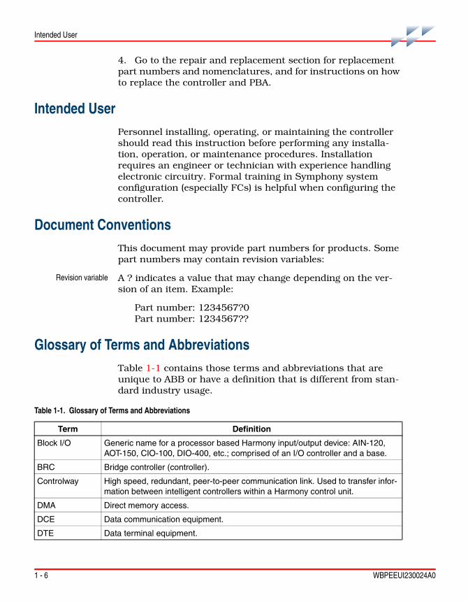
Intended UserPersonnel installing, operating, or maintaining the controller should read this instruction before performing any installa-tion, operation, or maintenance procedures. Installation requires an engineer or technician with experience handling electronic circuitry. Formal training in Symphony system configuration (especially FCs) is helpful when configuring the controller.
Document ConventionsThis document may provide part numbers for products. Some part numbers may contain revision variables:
Revision variable A ? indicates a value that may change depending on the ver-sion of an item. Example:
Part number: 1234567?0Part number: 1234567??
Glossary of Terms and AbbreviationsTable 1-1 contains those terms and abbreviations that are unique to ABB or have a definition that is different from stan-dard industry usage.
Table 1-1. Glossary of Terms and Abbreviations
Term Definition
Block I/O Generic name for a processor based Harmony input/output device: AIN-120, AOT-150, CIO-100, DIO-400, etc.; comprised of an I/O controller and a base.
BRC Bridge controller (controller).
Controlway High speed, redundant, peer-to-peer communication link. Used to transfer infor-mation between intelligent controllers within a Harmony control unit.
DMA Direct memory access.
DCE Data communication equipment.
DTE Data terminal equipment.

Reference Documents
WBPEEUI230024A0 1 - 7
Reference DocumentsTable 1-2 contains a list of documents referenced in this instruction that provide information on controller firmware and related hardware.
Hnet Communications path between Harmony controller and block I/O.
HSI Human system interface.
Executive block Fixed function block that determines overall controller operating characteristics.
Function block The occurrence of a FC at a block address of a controller.
FC Function code. An algorithm which manipulates specific functions. These func-tions are linked together to form the control strategy.
I/O Input/output.
I/O controller Houses the block I/O circuitry; part of Harmony block I/O.
I/O expander bus
Parallel communication bus between the Harmony rack controller and Harmony rack I/O controllers.
MFT Machine fault timer. Reset by the processor during normal operation. If not reset regularly, the MFT times out and the controller stops.
MMU Module mounting unit. A card cage that provides electrical and communication support for Harmony rack controllers.
Module bus Low speed peer-to-peer communications link. Used to transfer information between intelligent controllers and INFI 90 controllers within a Harmony control unit.
PBA Processor bus adapter (PBA).
TU Termination unit. Provides input/output connection between plant equipment and the Harmony rack controllers.
Table 1-1. Glossary of Terms and Abbreviations (continued)
Term Definition
Table 1-2. Reference Documents
Number Title
WBPEEUI200502?? Module Mounting Unit (IEMMU11, IEMMU12, IEMMU21, IEMMU22)
WBPEEUI210504?? Function Code Application Manual, Symphony
WBPEEUI230022?? Analog Control Station (IISAC01)
WBPEEUI240751?? Harmony Input/Output System
WBPEEUI240762?? IMDSO14 Digital Output Module
WBPEEUI260039?? NTMP01 Multifunction Processor Termination Unit

1 - 8 WBPEEUI230024A0
Related Nomenclatures
Related NomenclaturesTable 1-3 lists nomenclatures related to the controller.
SpecificationsTable 1-4 lists the specifications for the controller and PBA.
WBPEEUI270002?? Primary Interface, Composer
WBPEEUI270003?? Automation Architect, Composer
Table 1-2. Reference Documents (continued)
Number Title
Table 1-3. Related Nomenclatures
Nomenclature Description
IEMMU11, IEMMU12, IEMMU21, IEMMU22
MMU
IISAC01 Analog control station
NTMP01 Field termination panel
Table 1-4. Specifications
Property Characteristic/Value
Microprocessor 32-bit processor running at 160 MHz
MemoryController
All memory has 32-bit data path
Power requirementsController
PBA
5 VDC at 2 A; 10 W typical
5 VDC at 100 mA; 0.5 W typical
Station support 64 40-kbaud serial stations (IISAC01) or eight 5-kbaud serial stations (refer to Station Link for more information)
Redundant controller communication link
4 MHz per byte per second (normal operation)
Programmability FCs, C, Batch 90 (future)
SDRAM NVRAM Flash ROMTotalTotal Available Total Available
8 Mbytes 7.56 Mbytes 512 kbytes 425 kbytes 2 Mbyte

Specifications
WBPEEUI230024A0 1 - 9
DimensionsController
PBA
35.56 mm wide, 177.80 mm high, 298.45 mm long(1.40 in. wide, 7.00 in.high, 11.75 in. long)
31.08 mm wide, 93.50 mm high, 130.50 mm long(1.22 in. wide, 3.68 in. high, 5.14 in. long)
WeightControllerPBA
0.70 kg (24.69 oz)0.14 kg (4.8 oz)
Communication ports 2 RS-232-C or 1 RS-232-C and 1 RS-485,1 IISAC01 channel (refer to Station Link for more information)
Ambient temperature 0° to 70°C (32° to 158°F)
Relative humidity 0% to 95% relative humidity up to 55°C (131°F) noncondensing0% to 45% relative humidity at 70°C (158°F) noncondensing
Atmospheric pressure Sea level to 3 km (1.86 mi)
Certifications (pending) CSA certified for use as process control equipment in ordinary (nonhazardous) locations.
Factory Mutual (FM)- Class I; Division II; Groups A, B, C, and D.
CE mark compliant for EMC directive and LV directive.
SPECIFICATIONS SUBJECT TO CHANGE WITHOUT NOTICE
Table 1-4. Specifications (continued)
Property Characteristic/Value

WBPEEUI230024A0

WBPEEUI230024A0 2 - 1
Section 2Description and Operation
IntroductionThis section explains the functionality of the controller using block diagrams and text. Block diagrams divide the operation of the controller.
OperationThe controller incorporates the power of a second generation 32-bit microprocessor operating at 160 megahertz. This is cou-pled with 32-bit wide memory design with an optimized inter-face. The microprocessor supplies superior performance capable of supplanting the need for external mainframes or minicomputers.
Control I/O is available from block I/O using Hnet or from Harmony rack I/O controllers using the I/O expander bus. The data within the controller may be exported to the Cnet communication network and to existing INFI-NET ® and Plant Loop communication systems.
In some processes, the effects of a control failure in the system can create dangerous situations or cause economic loss. To reduce the possibility of these problems occurring, redundant controllers provide increased availability.
Redundant controllers link directly to each other via the front-connected redundancy cable (refer to the Spare Parts List for the part number). Each controller uses a redundant high speed communication channel to accomplish this func-tion. If the primary controller fails, the redundant controller is waiting in standby mode and immediately takes over. The redundant controller has the same control strategy loaded in its memory as the primary controller and is ready to assume control. When operating in Hnet communication mode, the redundant communication channel ensures that single point failures will not prevent the redundant controller from being in a state of readiness to take over.

2 - 2 WBPEEUI230024A0
Circuitry
While the controller is directing a process, it also executes diagnostic routines. It is constantly checking the integrity of its hardware and firmware during normal operation. If the diagnostic routines discover a controller hardware or software problem, it makes that information available to the operator. The operator has access to this information through status LEDs on the controller faceplate and through reports received on the human system interface (HSI) in controller status bytes.
The controller uses a control block I/O on Hnet to support a station link that can handle up to 128 IISAC01 stations and is compatible with the Symphony system.
Two auxiliary RS-232-C ports and a serial station link are available through a cable connection via the PBA to a NTMP01 TU. This station link can handle up to 64 IISAC01 stations at a 40-kilobaud rate or eight stations at a five-kilobaud rate. Vari-ous handshake options are available via jumper configurations on the TU.
CircuitryThe controller has all the needed circuitry to operate as a stand-alone controller. DMA operation is supported for the sta-tion link. Figure 2-1 shows a block diagram of the controller circuitry.
Microprocessor
The microprocessor (Coldfire) is responsible for controller operation and control. The controller microprocessor is a 32-bit processor that runs from a 160 megahertz clock. The microprocessor executes synchronous access to 32-bit wide memories and an asynchronous access to all byte ports. Since the microprocessor is responsible for controller operation, it communicates with all blocks of the controller circuitry. The microprocessor operating system instructions and the FC library reside in the read only memory (flash ROM). The micro-processor carries out all control responsibilities as it executes the control strategy set up in its function block configuration.
The microprocessor constantly triggers the machine fault timer (MFT) circuit. If the microprocessor or software fails, the MFT circuit times out, issues a board wide reset, and the sta-tus LED turns red. This condition is a fatal controller error.

Circuitry
WBPEEUI230024A0 2 - 3
Clock and Real-Time Clock
The clock section provides the clock signals to drive the micro-processor and associated peripheral devices. The clock/timer section also includes a real-time clock.
Memory
The memory is made up of two megabytes of flash ROM, eight megabytes of SDRAM, and 512 kilobytes of NVRAM.
The flash ROM memory holds the operating system instruc-tions for the microprocessor. The SDRAM memory provides temporary storage and a copy of the system configuration. The NVRAM memory holds the system configuration (control strategy designed with FCs) and files for C applications. NVRAM memory retains whatever information it has, even when it loses power.
Figure 2-1. Functional Block Diagram
T 0127 2B
C LO C K
M IC RO P R O C E S S O R
M AC H IN EFAU LTTIM ER
32-B IT DATA PATH
16-BIT DATA PATH
R E D U N DA N T H N E T B U S
R O M N V R AM S R A M
L ED s,S W ITC H E S,
DATA B U FFE R S
8-B IT DATA PATH
D M A/P E R IP H E R AL C O N TR O L I/O
S TE E R IN GDATA
LO G IC
D UA LR ED U N DAN C Y
LIN K
C O N TR O LW AY /M O D U LE BU S
I/OE X PA N D E R
B U S
IISAC 01/D C S
D UA RT RTC
TOP B A
2 - 4 WBPEEUI230024A0
Circuitry
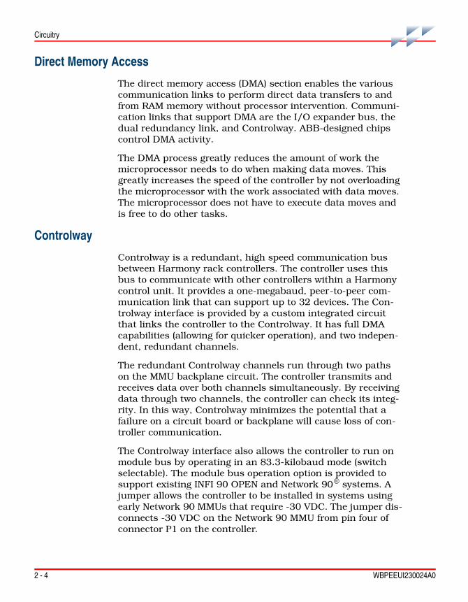
Direct Memory Access
The direct memory access (DMA) section enables the various communication links to perform direct data transfers to and from RAM memory without processor intervention. Communi-cation links that support DMA are the I/O expander bus, the dual redundancy link, and Controlway. ABB-designed chips control DMA activity.
The DMA process greatly reduces the amount of work the microprocessor needs to do when making data moves. This greatly increases the speed of the controller by not overloading the microprocessor with the work associated with data moves. The microprocessor does not have to execute data moves and is free to do other tasks.
Controlway
Controlway is a redundant, high speed communication bus between Harmony rack controllers. The controller uses this bus to communicate with other controllers within a Harmony control unit. It provides a one-megabaud, peer-to-peer com-munication link that can support up to 32 devices. The Con-trolway interface is provided by a custom integrated circuit that links the controller to the Controlway. It has full DMA capabilities (allowing for quicker operation), and two indepen-dent, redundant channels.
The redundant Controlway channels run through two paths on the MMU backplane circuit. The controller transmits and receives data over both channels simultaneously. By receiving data through two channels, the controller can check its integ-rity. In this way, Controlway minimizes the potential that a failure on a circuit board or backplane will cause loss of con-troller communication.
The Controlway interface also allows the controller to run on module bus by operating in an 83.3-kilobaud mode (switch selectable). The module bus operation option is provided to support existing INFI 90 OPEN and Network 90® systems. A jumper allows the controller to be installed in systems using early Network 90 MMUs that require -30 VDC. The jumper dis-connects -30 VDC on the Network 90 MMU from pin four of connector P1 on the controller.

Circuitry
WBPEEUI230024A0 2 - 5
Redundancy
Redundancy is accomplished via a redundant bridge controller link cable (refer to Spare Parts List for the part number) con-necting from the faceplate of the primary controller to the face-plate of the redundant controller. Refer to Appendix C for redundancy cabling information.
As the primary controller executes, the redundant controller waits in standby mode and receives a copy of block outputs over this link. If for any reason the primary controller fails, the redundant controller takes over without any process interrup-tion.
NOTES: 1. Firmware revision levels must be the same in both primary and redundant controllers. If the firmware revision level is different and a failover occurs, the redundant controller may operate erratically.
2. Installing or removing a redundant controller during a firmware download at either the source or destination end of the transfer may prevent the firmware download from completing successfully.
3. The BRC-300 controller cannot be redundantly connected to the BRC-100 or BRC-200.
Hnet Communication
An Hnet interface enables communication with Harmony block I/Os. All communication functions are handled by the Hnet application-specific integrated circuit (ASIC). Hnet is a 16-bit interface that operates via control registers in the I/O section of controller memory and a one-megabyte memory space for shared SDRAM.
Hnet and I/O expander bus communication can be active simultaneously if enabled, allowing the controller to utilize both Harmony block I/O and Harmony rack I/O controllers to direct a process. FC 90 (S3) controls what combination of I/O interfaces are active. Two selections are available: enable Hnet and I/O expander bus and enable I/O expander bus only.
Physical connection is provided by a direct connection from the controller P3 connector to the PBA P5 connector. The PBA mounts on the rear of the MMU and uses cables to connect to

2 - 6 WBPEEUI230024A0
Circuitry
the Harmony block mounting columns. The PBA provides Hnet physical layer functions, termination, and isolation relays.
I/O Expander Bus
The I/O expander bus interface is implemented using an ABB-designed integrated circuit. The microprocessor can select one of two modes of operation: DMA or auto mode. The controller software selects the mode of operation. Mode selec-tion is based on optimizing the number of bytes to be trans-ferred. In either mode of operation, the microprocessor does not need to wait for each byte to transfer (as in previous con-trollers).
The controller connects to the I/O expander bus through the P2 connector on the MMU backplane. It is an eight-bit parallel bus that provides the communication path for I/O data from Harmony rack I/O controllers. The I/O expander bus supports up to 64 low power rack I/O devices.
I/O Section
The I/O section interface allows the microprocessor to read the switches that tell it how to operate and set the controller address. This section also contains latches whose outputs connect to the status and error LEDs. This section monitors redundant controllers and outputs a signal to the controller active LED on the NTMP01. Upon failover, this output de-ener-gizes and the output of the redundant controller energizes its controller active LED on the NTMP01 as it takes over. Addi-tionally, the I/O section monitors the stop/reset pushbutton. When the pushbutton is pressed, the I/O section insures that the controller completes any I/O functions before it stops the controller.
Serial Channels
Two independent serial channels (RS-485) are available on the controller. Both serial channels are dedicated for language support (C). Clear to send (CTS) and request to send (RTS) handshake signals are supported. A DUART circuit on the controller supplies the serial channels with handshaking sig-nals. Clock signals for the baud rate generator are derived from an onboard, 7.3728-megahertz oscillator.

Circuitry
WBPEEUI230024A0 2 - 7
The PBA connects to an NTMP01 TU. I/O signals enter or leave the PBA through a cable connection to the TU. An NKTU01 or NKTU11 cable connects an NTMP01 TU with the PBA. Stan-dard D-type connectors are available on the TU.
To provide better noise immunity, both channels transmit and receive differential serial signals based on the RS-485 stan-dard. These signals are converted to normal RS-232-C voltage levels by the TU. Each channel is capable of supporting stan-dard RS-232-C baud rates up to 38.4 kilobaud. The TU also provides optical isolation to eliminate the possibility of intro-ducing ground loops into the system from improper cable shield grounding. Channel A (the terminal channel) can be selected to operate without the RS-485/RS-232-C conversion allowing it to be used with differential terminals or program-mable logic controllers (PLC).
Station Link
Station communication originates from a DUART circuit on the controller. This link controls the serial communication between the controller and the control stations. It has two modes of operation: Hnet transactions to a Harmony CIO-100 block I/O, or direct operation by the controller via a TU.
The Hnet-to-CIO block mode of operation allows stations to be placed at greater distances from the controller because the CIO block contains the physical interface to the station. The controller is capable of communicating with a total of 128 IISAC01 stations attached to a total of 64 control I/O (100/110) blocks. The controller can also directly connect to local IISAC01 stations. Eight stations can be supported at the five-kilobaud rate and up to 64 stations can be supported at the 40-kilobaud rate.
The controller makes this direct local connection through the PBA and appropriate termination hardware. Support for bypass stations requires a Harmony control I/O module (IMCIS12, IMQRS12) configured on the I/O expander bus.
NOTE: The system station maximum of 128 stations presumes that only Hnet- to-control block I/O communication mode is used.

2 - 8 WBPEEUI230024A0
Circuitry
Power
Power requirements are 5 VDC for logic power and for line drivers/receivers. The Hnet interface derives all other power requirements from the 5 VDC logic power. Power for the con-troller is supplied via the MMU connection to the controller P1 connector. The PBA receives 5 VDC logic power via its connec-tion to the controller. The PBA uses this power for Hnet termi-nation and to power the isolation relays.

WBPEEUI230024A0 3 - 1
Section 3Installation
IntroductionThis section explains how to set up and install the controller. Read and complete the steps in the order they appear before operating the controller.
The controller requires a PBA to support Hnet communication, serial channels, and the station link.
NOTES: 1. The controller uses connections to the MMU backplane that served other functions in earlier Network 90 systems. To avoid potential controller damage, evaluate your system for compatibility prior to controller installation. Earlier Network 90 systems applied -30 VDC to pins three and four of the controller connector P1. This voltage is not required for Symphony and INFI 90 OPEN controllers. In Symphony and INFI 90 OPEN systems, pin four is used for the Controlway bus.
2. If the system contains controllers that require -30 VDC, set jumper J3 to the 30 VDC position (jumper pins one and two). Doing so allows the installation of the controller in a MMU that uses -30 VDC and limits communication to mod-ule bus. Refer to Table 3-6 for more information about setting jumper J3.
Special HandlingObserve these steps when handling electronic circuitry:
NOTE: Always use ABB's field static kit (part number 1948385A1 - consisting of two wrist straps, ground cord assembly, alligator clip and static dissipative work surface) when working with the controllers. The kit grounds a technician and the static dissipative work surface to the same ground point to prevent damage to the controllers by electrostatic discharge.
1. Use Static Shielding Bag. Keep the controllers in the static shielding bag until you are ready to install them in the system. Save the bag for future use.
2. Ground Bag Before Opening. Before opening a bag con-taining a controller with semiconductors, touch it to the equip-ment housing or a ground to equalize charges.

Unpacking and Inspection
3 - 2 WBPEEUI230024A0
3. Avoid Touching Circuitry. Handle controllers by the edges; avoid touching the circuitry.
4. Avoid Partial Connection of Semiconductors. Verify that all devices connected to the controllers are properly grounded before using them.
5. Ground Test Equipment.
6. Use an Antistatic Field Service Vacuum. Remove dust from the controller if necessary.
7. Use a Grounded Wrist Strap. Connect the wrist strap to the appropriate grounding plug on the power entry panel. The grounding plug must be effectively connected to the earth grounding electrode system through the AC safety ground.
8. Do Not Use Lead Pencils to Set Dipswitches. To avoid contamination of dipswitch contacts that can result in unnec-essary circuit board malfunction, do not use a lead pencil to set a dipswitch.
Unpacking and Inspection1. Examine the hardware immediately to verify that it has not been damaged in transit.
2. Notify the nearest ABB sales office of any damage.
3. File a claim for any damage with the transportation com-pany that handled the shipment.
4. Use the original packing material and container to store the hardware.
5. Store the hardware in an environment of good air quality, free from temperature and moisture extremes.
Dipswitches and JumpersThis section explains how to configure and install the control-ler. After installing the controller, a function block configuration must be created to define the functions the con-troller will perform.

Dipswitches and Jumpers
WBPEEUI230024A0 3 - 3
The controller has three dipswitches and two jumpers that are to be configured. Each dipswitch has eight poles. Figure 3-1 shows the location of the dipswitches and jumpers on the cir-cuit board.
Dipswitch SW5 sets the controller address, bus speed, and operation mode (normal/diagnostic). Dipswitch SW2 sets con-troller options, enables special operations, and enables diag-nostic operations. Dipswitch SW4 sets MMU and memory options.
Jumpers J2 and J3 define controller functions and operation. Jumper J2 sets the diagnostic RS-232-C port for operation as DCE or data terminal equipment (DTE). Jumper J3 disengages -30 VDC from the controller when installing it in a MMU that supplies -30 VDC to other controllers.
Dipswitch SW3 is not used (refer toDipswitch SW3 - Controller Options for more information). Jumpers J1, J14, and J15 must not be moved from their fac-tory settings. Refer to Table 3-6 for more information.
Dipswitch poles marked not used must be set to the default settings listed in the appropriate table. The controller may not operate properly if these dipswitches are improperly set. Since factory settings do not reflect default settings, it is imperative that all dipswitch settings be checked before putting the con-troller into operation.
Figure 3-1. Controller Layout
T01274D
J2
J3
SW5 SW2 S 3 SW4WJ14
J15J1

Dipswitches and Jumpers
3 - 4 WBPEEUI230024A0
Dipswitch SW5 - Controller Address
Dipswitch SW5 sets the controller address, enables controller diagnostics, and sets the bus mode. The controller can have an address from zero through 31. Table 3-1 explains the func-tions set by dipswitch poles one through three. Dipswitch poles four through eight set the controller address.
NOTES: 1. SW5 provides a module bus option to support existing INFI 90 OPEN and early Network 90 systems. All controllers within a process control unit must be set to communicate on the same type of communication bus, either Controlway or module bus.
2. Addresses of redundant controllers must be identical.
Dipswitch SW2
There are two options when configuring dipswitch SW2: nor-mal operating options and special operations.
Normal Operating Options
Dipswitch SW2 sets controller options that are available when the controller is in normal operation. Refer to Table 3-2 for option setting information. The options listed in this table apply to normal operation. Normal operation options are enabled when dipswitch SW2 pole one is set to closed (on). If dipswitch SW2 pole one is set to open (off), special operations are enabled. Refer to Special Operations for a description.
NOTE: Poles one through seven must have the same setting for both control-lers when using redundant controllers.
Table 3-1. Dipswitch SW5 Settings (Operation)
Pole Setting Function
1 0 Normal run
1 Enable diagnostics using dipswitch SW2
2 0 Not used - do not change setting
31 0 Controlway (1 Mbaud)
1 Module bus (83.3 kbaud) or -30 VDC operation
NOTE: 0 = closed or on, 1 = open or off.1. The module bus setting is for support of existing INFI 90 OPEN and Network 90 systems.
Dipswitches and Jumpers
WBPEEUI230024A0 3 - 5
Special Operations
The special operations feature provides a means to configure the controller to perform a one-time special operation rather than entering its normal mode of operation. Setting dipswitch SW2 pole one to open (off) enables the special operation mode. Poles two through eight select the special operation. The fol-lowing steps explain how to set the controller for special opera-
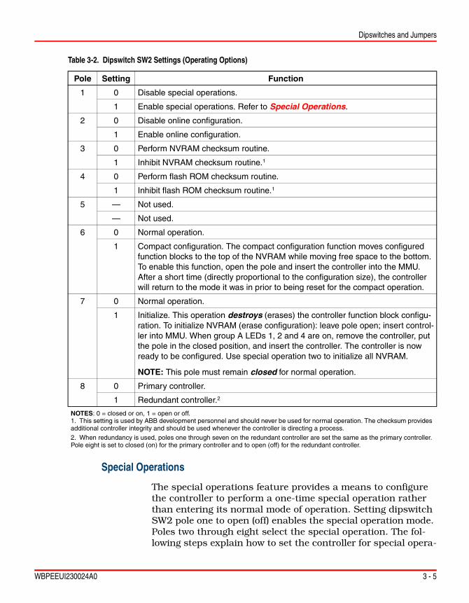
Table 3-2. Dipswitch SW2 Settings (Operating Options)
Pole Setting Function
1 0 Disable special operations.
1 Enable special operations. Refer to Special Operations.
2 0 Disable online configuration.
1 Enable online configuration.
3 0 Perform NVRAM checksum routine.
1 Inhibit NVRAM checksum routine.1
4 0 Perform flash ROM checksum routine.
1 Inhibit flash ROM checksum routine.1
5 — Not used.
— Not used.
6 0 Normal operation.
1 Compact configuration. The compact configuration function moves configured function blocks to the top of the NVRAM while moving free space to the bottom. To enable this function, open the pole and insert the controller into the MMU. After a short time (directly proportional to the configuration size), the controller will return to the mode it was in prior to being reset for the compact operation.
7 0 Normal operation.
1 Initialize. This operation destroys (erases) the controller function block configu-ration. To initialize NVRAM (erase configuration): leave pole open; insert control-ler into MMU. When group A LEDs 1, 2 and 4 are on, remove the controller, put the pole in the closed position, and insert the controller. The controller is now ready to be configured. Use special operation two to initialize all NVRAM.
NOTE: This pole must remain closed for normal operation.
8 0 Primary controller.
1 Redundant controller.2
NOTES: 0 = closed or on, 1 = open or off.1. This setting is used by ABB development personnel and should never be used for normal operation. The checksum provides additional controller integrity and should be used whenever the controller is directing a process.2. When redundancy is used, poles one through seven on the redundant controller are set the same as the primary controller. Pole eight is set to closed (on) for the primary controller and to open (off) for the redundant controller.

Dipswitches and Jumpers
3 - 6 WBPEEUI230024A0
tions and reset it for normal operation. Table 3-3 shows the dipswitch settings and explains each special operation.
To use special operations:
1. Set dipswitch SW2 pole one to open (off).
2. Set poles two through eight per Table 3-3. Begin with spe-cial operation two.
3. Insert the controller in its slot in the MMU (refer to Controller Installation).
4. When the special operation is complete, the status LED turns red and LEDs one through six illuminate.
5. Remove the controller.
Table 3-3. Dipswitch SW2 Settings (Special Operations)
Special Operation
Dipswitch Pole Description
1 2 3 4 5 6 7 8
0 1 0 0 0 0 0 0 0 Force the controller into configure mode.
1 1 0 0 0 0 0 0 1 Force the controller into Configure mode and force Expander Bus Only mode.
21 1 0 0 0 0 0 1 0 Initialize and format all NVRAM configuration space for Plant Loop protocol.
3 1 0 0 0 0 0 1 1 Force the controller into Configure mode and force Expander Bus and H-Net mode.
4 1 0 0 0 0 1 0 0 Cnet or INFI-NET protocol enable. This allows the controller to use the Cnet or INFI-NET capabilities.
5 1 0 0 0 0 1 0 1 Permit segment modification (allows change to segment scheme configured with FC 82, specification S1).
6 1 0 0 0 0 1 1 0 Enable time-stamping. This operation instructs the controller to generate time information with point data. It is applicable only to Cnet or INFI-NET systems.
162 1 0 0 1 0 0 0 0 Set Propagation Delay Time for distance of 1200 meters (default as set by Special operation 2).
182 1 0 0 1 0 0 1 0 Set Propagation Delay Time for distance of 3000 meters.
192 1 0 0 1 0 0 1 1 Set Propagation Delay Time for distance of 2000 meters.
202 1 0 0 1 0 1 0 0 Set Propagation Delay Time for distance of 800 meters.
NOTES: 0 = closed or on, 1 = open or off.1. Special operation 2 is for support of existing INFI 90 OPEN and Network 90 systems.2. Refer to Harmony Controller I/O Bus Length for more information.

Dipswitches and Jumpers
WBPEEUI230024A0 3 - 7
6. Repeat Steps 2 through 8 for any other special operation desired.
NOTE: Do special operation two as the first step of the controller installation. If installing the controller in a Cnet or INFI-NET environment, do special opera-tion four next. For time-stamping, do special operation six next. To start back at the beginning, perform operation two again.
7. When all special operations are complete, reset pole one on dipswitch SW2 to the closed (on) position.
8. Poles two through eight (controller options) should be set for the desired controller operation per Table 3-2.
9. Insert the controller in its slot. It will begin normal operation.
Harmony Controller I/O Bus Length
In applications where a Harmony Repeater is used, the con-troller uses a default bus length of 1200 meters after the ini-tialize/format special operation 0x02 = 0000010. If the default bus length of 1200 meters is being used then no additional special operation is required after special operation 0x02 = 0000010; that is, special operation 0x10 = 0010000 is not performed since it is the default (Table 3-4).
Additional proptime special operations can select one of four proptimes (Table 3-4). The redundant controller must have the same proptime special operation performed before its startup. The proptime is measured at startup by both the primary and redundant controllers. These additional proptimes allow remote Harmony block I/Os to be located up to 3000 meters from the local controller.
The redundant controller will red light with a 0x16 = 00010110 = LEDs 2, 3, and 5 special operation when the selected proptime does not match the measured proptime of the current bus master (primary controller). The configura-tion download via the redundancy link contains the primary’s format information and stores the configured proptime in the redundant’s format information during the download.
The block I/O uses a default bus length of 1200 meters at startup. With Harmony block I/O firmware release E.0 or later, the default proptime is overridden at startup when a controller is already online and the block I/O detects a bus master

Dipswitches and Jumpers
3 - 8 WBPEEUI230024A0
(primary controller). The proptime is then set to the measured value to prevent a conflict. The block I/O performs a back-ground proptime check once a second. A sequential counter is started when a valid measured value is different than the cur-rent selected value. The proptime is set to the new measured value if the measured value remains the same for five sequen-tial checks (five seconds).
This mode of operation permits the bus to be in a nonfunc-tional state when proptime is changed for up to five seconds after the controller has started the Hnet interface as a control-ler type. This is an acceptable state because the bus had been previously stalled; that is, a special operation on the primary controller with the redundant controller removed. Again, the primary controller can change its proptime only via a special operation and the redundant controller must be offline before inserting the primary controller with the new proptime. The tens digit of the FC 89 block output #31999 on the controller reports the configured bus distance.
Table 3-4 shows the proptime special operations.
To use proptime special operations:
1. Set dipswitch SW2 pole one to open (off).
2. Set poles two through eight per Table 3-4.
Table 3-4. Proptime Special Operations
Special Operation
SW2
Dipswitch Pole(Poles 2-8)
Fiber Distance (m)
Maximum Number of
Blocks at 250 msecs
FC 89 Output Tens Digit
(Block #31999)2 3 4 5 6 7 8
0x10(Default)
0 0 1 0 0 0 0 1200 64 0
0x121 0 0 1 0 0 1 0 3000 35 2
0x13 0 0 1 0 0 1 1 2000 50 3
0x14 0 0 1 0 1 0 0 800 90 4
NOTES: 0 = closed or on, 1 = open or off.1. The current RFO fiber optic repeater hardware can only support single run fiber lengths of 2000 m.2. The 0x10 = 0010000 (default) is the current bus length of all firmware revisions currently released.3. The maximum number of recommended Harmony block I/Os is calculated for a scan rate of 250 milliseconds and is the total of local and remote blocks on the bus. Proportionally more block I/Os can be installed for slower scan rates.4. This table is not compatible with Block Processor Firmware Revision C.1. The controller performing a firmware download to a revision C.1 block must be set to a default 1200 meter distance for the download to be successful. The default distance of 1200 meters for BRC-300 Firmware Revision G.0 is compatible with the default distance of 1500 meters for Block Processor Firmware Revision C.1.

Dipswitches and Jumpers
WBPEEUI230024A0 3 - 9
3. Insert the controller in its slot in the MMU (refer to Controller Installation).
4. When the special operation is complete, the status LED turns red and LEDs one through six illuminate.
5. Remove the controller.
6. Repeat Steps 2 through 8 for any other special operation desired.
7. When all special operations are complete, reset pole one on dipswitch SW2 to the closed (on) position.
8. Poles two through eight (controller options) should be set for the desired controller operation per Table 3-2.
9. Insert the controller in its slot. It will begin normal operation.
Dipswitch SW3 - Controller Options
Dipswitch SW3 is not used. All poles should be set to closed (on).
Dipswitch SW4 - Controller Options
Dipswitch SW4 sets additional controller options. This dipswitch should be set to the user settings shown in Table 3-5.
Jumpers
There are a two jumpers (J2 and J3) on the controller that can be configured. Refer to Table 3-6 for an explanation of the functions set by jumpers.
Table 3-5. Dipswitch SW4 Settings (Controller Options)
Pole Setting Function
1 - 5 0 Not used.
6 - 8 1 1 1 Cache enabled1.
NOTE: 0 = closed or on, 1 = open or off.1. Cache should always be enabled.

MMU Preparation
3 - 10 WBPEEUI230024A0
MMU PreparationPreparing the MMU consists of identifying the mounting slot, installing the required dipshunts, verifying the Controlway cable is installed, installing the PBA, PBA cables, and Hnet terminator.
Controller Slot Assignments
Controller placement within the MMU is important. The con-troller requires a PBA to use Hnet. The controller connects to the PBA at the rear of the MMU. Redundant controllers require mounting in adjacent MMU slots.
Dipshunts
Dipshunts are required if redundancy and/or the I/O expander bus is being used. Check to see that dipshunts are in place between all controller slots associated with one I/O expander bus. One dipshunt goes between each controller slot to maintain bus continuity.
Table 3-6. Jumpers Settings (J1 through J3 and J14 and J15)
Jumper Setting Function
J1 Open Do not change. Must remain open for normal operation.
J2 Vertical1 Sets the RS-232-C diagnostic port to operate as DCE.
Horizontal Sets the RS-232-C diagnostic port to operate as DTE.
J3 1-2 Disconnects Controlway for operation in MMUs that have -30 VDC (early Network 90).
2-3 Allows operation in MMUs that have Controlway communication. This setting must be used if dipswitch SW5 selects Controlway.
J14 1-2 Do not change. Must remain in position 1-2 for normal operation.
J15
NOTE: 0 = closed or on, 1 = open or off.1. Used by ABB service personnel. The J2 setting does not affect the controller during normal operation.
WARNINGDisconnect power before installing dipshunts on the MMU backplane. Failure to do so will result in contact with cabinet areas that could cause severe or fatal shock.

MMU Preparation
WBPEEUI230024A0 3 - 11
Controlway Cable
NOTE: Because of high speed transaction constraints, a maximum of eight related MMUs (Controlways linked by cable) can be installed in one enclosure. The number of interconnected MMUs should be kept to a minimum to avoid crosstalk and interference. Controlways cannot be cable linked from enclosure to enclosure.
Install the Controlway cable in MMUs as follows:
1. Attach one end of the cable (twisted three-wire) to the bot-tom three tabs on the lower left of the MMU backplane (facing from behind). Refer to Figure 3-2.
2. Attach (in the same sequence) the other end of the cable to the bottom three tabs on the lower left of the next MMU back-plane.
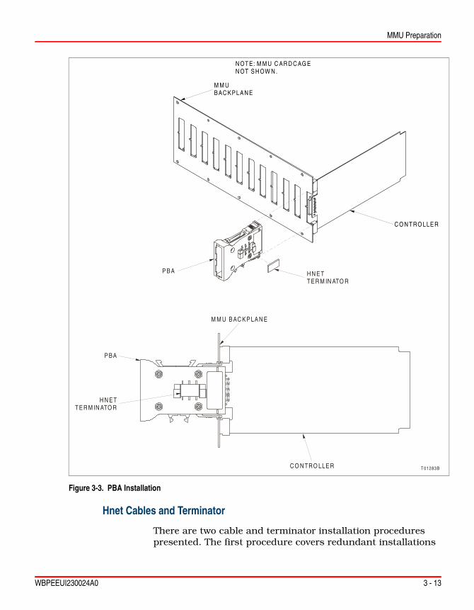
PBA Installation
Hnet is the communication path between a controller and Har-mony block I/Os. A PBA is required to connect a controller to Hnet, connect redundant Hnet to redundant controllers, and provide a connection point for the NTMP01 TU. The NTMP01
Figure 3-2. Controlway Cable Installation
T 00 063 A

MMU Preparation
3 - 12 WBPEEUI230024A0
TU provides a connection for the two auxiliary serial ports and a direct five-kilobaud or 40-kilobaud station link.
Mounting
There are two PBA mounting procedures presented. The first procedure covers redundant installations (two PBAs) and the second procedure covers nonredundant installations (single PBA). Figure 3-3 shows an example of how the PBA mounts to the MMU backplane.
Redundant PBA To mount redundant PBAs:
1. Locate and verify the adjacent MMU slots assigned to the redundant controllers. Refer to Controller Slot Assignments in this section for more information.
2. For systems using both Hnet and I/O expander bus, or only I/O expander bus, verify there is a dipshunt installed between the adjacent MMU slots of each controller using a particular I/O expander bus. Install any needed MMU dip-shunts. This is needed for controller redundancy.
Refer to Dipshunts in this section for information on how to verify a controller communication bus configuration.
3. Insert each PBA into their locked position on the MMU backplane (P5 connector on the PBA and P3 connector on the controller).
NOTE: The PBA is keyed and can only be inserted into the MMU backplane one way.
Single PBA To mount a single PBA:
1. Locate and verify the MMU slots assigned to the control-lers. Refer to Controller Slot Assignments in this section for more information.
2. Insert the PBA into its locked position on the MMU back-plane (P5 connector on the PBA and P3 connector on the con-troller).
WARNINGDisconnect power before installing dipshunts on the MMU backplane. Failure to do so will result in contact with cabinet areas that could cause severe or fatal shock.
MMU Preparation
WBPEEUI230024A0 3 - 13
Hnet Cables and Terminator
There are two cable and terminator installation procedures presented. The first procedure covers redundant installations
Figure 3-3. PBA Installation
T 01283B
H N E TT ER M IN ATO R
C O N TRO LLE R
P BA
H N E TT E R M IN ATO R
M M U B AC K P LA N E
P B A
C O N T RO LLE R
M M UB AC KP LA N E
N OT E: M M U C AR D C AG EN OT S H OW N .

MMU Preparation
3 - 14 WBPEEUI230024A0
(two PBAs), and the second procedure covers nonredundant installations (single PBA). Refer to Figure 3-4 for PBA cable connector assignments.
Redundant PBA To install the PBA cables for a redundant configuration (two PBAs):
1. Install the redundant processor bus adapter cable.
NOTE: Refer to Section 8 and Appendix B to determine the type and length of the cable.
a. Position the end socket connector on the PBA bracket so that the pins of the cable are facing outward.
b. Install a terminator to the end socket connector on the redundant processor bus adapter cable.
NOTE: The end socket connector is keyed, but the terminator is not. The termi-nator can be installed in any direction.
Figure 3-4. PBA Connector Identification
T04754C
P1
P5P3
REDUNDANT PROCESSORBUS ADAPTER CABLE
(P-MK-HRM-PBA1?00?)
CONNECTION TOTU CABLE FOR
STATION LINKTO P3 OFCONTROLLER
TO HARMONYI/O COLUMN
REDUNDANTPBA
TERMINATOR
PROCESS BUS ADAPTER(P-HC-BRC-PBA20000)
P4
NO CABLE REQUIRED FOR BRC-300 APPLICATIONS

MMU Preparation
WBPEEUI230024A0 3 - 15
c. Insert the next keyed connector on the redundant pro-cessor bus adapter cable into the P1 connector on the PBA with the terminator mounted to it.
d. Insert the next keyed connector on the redundant pro-cessor bus adapter cable into the P1 connector on the next redundant PBA.
e. Attach the final cable connector to the I/O column after the PBAs have been mounted. Continue to Mounting in this section to mount the redundant PBAs.
NOTE: TU cables for the direct station link can be installed at any time after the PBAs are installed. Refer to Appendix B for more information.
Single PBA To install the PBA cables for a nonredundant configuration (one PBA):
1. Install the redundant processor bus adapter cable.
NOTE: Refer to Section 8 and Appendix B to determine the type and length of the cable.
2. Position the end socket connector on the PBA bracket so that the pins of the cable are facing outward.
3. Install a terminator to the end socket connector on the redundant processor bus adapter cable.
NOTE: The end socket connector is keyed, but the terminator is not. The termi-nator can be installed in any direction.
4. Insert the next keyed connector on the redundant proces-sor bus adapter cable into the P1 connector on the PBA with the terminator mounted to it.
5. The next keyed connector on the cable is used only for redundant installations and has no purpose in single PBA installations. It can be left hanging.
6. Attach the final cable connector to the I/O column after the PBAs have been mounted. Continue to Mounting in this section to mount the PBA.
NOTE: The TU cable for the direct station link can be installed at any time after the PBA is installed. Refer to Appendix B for more information.

Controller Installation
3 - 16 WBPEEUI230024A0
Controller Installation
Pre-Installation Check
1. To determine if the MMU uses -30 VDC, measure the volt-age at each faston with respect to system common.
2. If -30 VDC is present, set jumper J3 and dipswitch SW5 to the appropriate positions.
Installation
Before installing a controller:
1. Check all controller dipswitch and jumper settings (normal and special operation).
2. Verify that the PBA if required, is attached to the proper slot on the MMU backplane.
NOTE: Controllers can be installed and removed under power. When doing so, the status LED will turn red momentarily and then turn green. If it does not, refer to Section 5 for troubleshooting information.
To install a controller:
1. Slide the controller into its mounting slot while guiding the top and bottom edges of the controller along the top and bot-tom rails of its assigned slot in the MMU.
CAUTION
Do not operate the controller with the MFT circuit disabled (J1 pins 1-2 connected). Unpredictable controller outputs and con-figuration corruption can result. The unpredictable controller outputs can damage control equipment connected to the con-troller.
To avoid potential controller damage, evaluate the system for compatibility prior to controller installation. This controller uses connections to the MMU backplane that served other functions in early Network 90 systems.

Controller Installation
WBPEEUI230024A0 3 - 17
2. Push only on the latching screws on the faceplate until the rear edge of the controller is firmly seated in the P5 connector of PBA.
NOTE: If installing the controller under power, verify the status LED momen-tarily lights red and then remains green. If this does not occur, refer to the trou-bleshooting section for corrective action.
3. Turn the two latching screws ½-turn either way to lock the controller in place. The controller is locked into place when the open end of the slot on each latching screw faces the center of the faceplate.
4. Repeat this procedure for redundant controllers.
5. After the redundant controller is installed, connect the redundancy cable (refer to Spare Parts List for more informa-tion) between the faceplates of the adjacent redundant control-lers. The cable is keyed and only inserts in one orientation.
Removal
To remove a controller:
1. Before removing a controller that is under power, always push the stop/reset button of that controller once. This action will allow the controller to perform an orderly shutdown and will result in the status LED turning red and group A LEDs 1-6 turning red.
2. If the controller is non redundant, the controller may now be unlatched by turning the screws ½-turn either way and removed from the mounting slot by pulling on the screws.
3. If the controller is redundant, the redundancy cable must be removed. Once this is complete, the controller may now be unlatched by turning the screws ½-turn either way and removed from the mounting slot by pulling on the screws.

WBPEEUI230024A0

WBPEEUI230024A0 4 - 1
Section 4Operating Procedures
IntroductionThe first part of this section explains LED indications,stop/reset, and controller startup. The last part explains the three modes of operation.
Controller LEDsThere are 17 total LEDs (red/green status LED, group A LEDs 1-8, and group B LEDs 9-16) that are visible through the face-plate window. 16 LEDs relate to processor status and one is the controller status LED (Fig. 4-1).
Figure 4-1. Faceplate of Controller
BRC-300RED/GREEN STATUS
GROUP A AND B LED INDICATORS
REDUNDANCY CONNECTOR
STOP/RESET
T01273D
12345678

4 - 2 WBPEEUI230024A0
Controller LEDs
NOTES: 1. Both groups of LEDs one through eight are on when the system is first coming up. This is normal. It means that the controller is not yet online.
2. Group B LEDs can only be seen when the controller is removed from the cabinet and the faceplate has been taken off. These LEDs are primarily for diagnostics only, not for normal operation.
Front Panel LEDs
Group A LEDs 1-8 display codes if a controller error occurs during normal operation. Additionally, in redundant configu-rations, they show which controller is the primary and which is the redundant. Group A LEDs seven and eight are on if the controller is primary; group A LED eight is on if the controller is redundant. If an error occurs, the status LED turns red and the group A LEDs light up to display the error code (Table 5-1).
Group B LEDs 9-16 display the pass and fail counts when the controller is in diagnostic mode.
Red/Green Status LED
The status LED is a red/green LED. It shows the controller operating condition. There are four possible states.
Off No power to the controller, or the controller is powered and jumper J4 is installed. Jumper J4 must remain open for nor-mal operation. The status LED momentarily goes off when the microprocessor initializes on startup.
Solid Green The controller is in execute mode.
Flashing Green The controller is in execute mode but there is an NVRAM checksum error, or the controller is in the configure or error mode.
Solid Red The controller diagnostics have detected a hardware failure, configuration problem, etc., and stopped the controller. Addi-tionally, the group A LEDs will illuminate in a certain sequence to display the error code. May also indicate that the module has been stopped by the stop/reset pushbutton.

Stop/Reset Switch
WBPEEUI230024A0 4 - 3
Stop/Reset SwitchNOTES: 1. Do not remove an operational controller under power unless the stop/reset switch has been depressed once and the controller has halted (sta-tus LED is red and group A LEDs one through six are on). This procedure must be followed when removing a controller from a redundant configuration. An operational controller must halt operation before control passes to the redun-dant controller.
2. Firmware revision levels must be the same in both primary and redundant controllers. If the firmware revision levels are different and a failover occurs, the redundant controllers may operate erratically.
The stop/reset switch is a two-hit switch. It stops the control-ler in an orderly manner, preventing glitches on the bus. The switch is accessible through the opening on the faceplate (Fig. 4-1). Since the opening is small, pressing the switch requires a thin round object. Pressing the switch once stops operation. Always stop the controller before removing it from the MMU. Stopping the controller this way causes it to:
• Save and lock the controller configuration.
• Complete any nonvolatile memory write operations in progress.
• Deactivate all communication links.
• Transfer control from the primary controller to the redun-dant controller in redundant configurations.
• Change the status LED color to red.
Once the controller is stopped, pressing the switch again resets the controller. Use the reset mode to:
• Reset the default values to the power-up values.

4 - 4 WBPEEUI230024A0
Startup
• Recover from a controller time-out or operator-initiated stop.
NOTE: Pressing and holding the stop/reset switch provides no additional func-tionality over pressing and releasing the switch. It will only stop the controller. To stop the controller, press and release the stop/reset switch. To reset the con-troller, press the stop/reset switch a second time. If the controller halts due to an error (causing the status LED to turn red), a single push of the stop/reset switch resets the controller.
StartupWhen power is applied to the controller, it does an internal check, checks its configuration, and builds the necessary databases.
During startup of the primary controller, the front panel LEDs will go through the following sequence:
1. All front panel LEDs will illuminate.
2. The status LED will change from red to green.
3. Group B LEDs one through eight will go out.
4. Group A LEDs one through six will go out.
During startup of the redundant controller, the front panel LEDs will go through the following sequence:
1. All front panel LEDs will illuminate.
2. The status LED will change from red to green.
3. All LEDs will go out.
4. Group A LED seven will illuminate red and then go out.
5. Group A LED eight will illuminate red.
If the appropriate LEDs do not illuminate, refer to Section 5 for more details.
Modes of OperationThe controller has three operating modes: execute, configure, and error.
Modes of Operation
WBPEEUI230024A0 4 - 5
Execute The execute mode is the normal mode of operation. In this mode, the controller communicates with block I/Os, rack I/O controllers, and other control modules. It executes control configurations, reads inputs, and updates outputs. The con-troller also processes exception reports, and configuration and control messages.
Configure Use the configure mode to enter or modify control strategies. The controller receives configuration commands over Control-way and changes the data in the NVRAM memory.
NOTE: The process of configuring the controller requires information from at least two documents. The Function Code Application Manual contains all of the information needed to design a control strategy. The instruction for the par-ticular configuration tool being used (Composer) explains the steps required to download control strategies into controller memory.
Error The controller goes into error mode whenever the built-in sys-tem diagnostics detect a hardware or configuration error. If a hardware error is detected, the controller halts and displays the error code using group A LEDs one through eight.
If a configuration error is detected, the controller resets and enters error mode and displays the error code using group A LEDs 1-8. Additional information about the configuration error is available in bytes 3, 4, and 5 of the module status. Refer to tables 5-6 and 5-7 in Controller Status Summary for more information.
If an NVRAM error is detected, the status LED flashes, but the controller continues to operate. This is possible because a copy of the configuration is held in SDRAM and executed from there. The next time the controller is reset it will not start up, but will fail with an NVRAM error.

WBPEEUI230024A0

WBPEEUI230024A0 5 - 1
Section 5Troubleshooting
IntroductionThis section contains controller troubleshooting information. Included is information on controller error codes, trouble-shooting flowcharts, diagnostic routines, and the controller status summary.
Error codes provide specific controller fault information and appropriate corrective action. Troubleshooting flowcharts pro-vide a quick look at hardware associated problems that may occur during controller installation and startup. Diagnostic tests help determine if there is a problem with controller com-ponents or circuitry. They are useful for testing the controller when the system is down or there is some other means of con-trolling the process. For example, use the redundant controller (if redundant controllers are installed) to control the process while testing the primary controller. The controller status sum-mary is a 16-byte controller status record that provides sum-mary flags for error conditions, controller type, and firmware revision level.
Error CodesController error codes are listed in Table 5-1. The controller displays error codes on group A LEDs. Table 5-2 lists status LED states and other conditions that are indicated by LEDs.
Table 5-1. Error Codes
Code1 LEDCondition Corrective Action
8 7 6 5 4 3 2 1
01 0 0 0 0 0 0 0 1 NVRAM checksum error Initialize NVRAM. If error recurs call ABB field service.
02 0 0 0 0 0 0 1 0 Analog input calibration Check I/O controller error.
03 0 0 0 0 0 0 1 1 I/O controller status bad Check controller status and I/O controllers.

5 - 2 WBPEEUI230024A0
Error Codes
04 0 0 0 0 0 1 0 0 Checkpoint buffer allocation error
1. Reduce function block configuration size.2. Reset controller module.3. Replace controller module.
05 0 0 0 0 0 1 0 1 Configuration error (undefined block)
Check controller status (undefined block).
06 0 0 0 0 0 1 1 0 Configuration error (data type mismatch)
Check controller status (data type) control-lers.
08 0 0 0 0 1 0 0 0 Trip block activated Check controller status.
09 0 0 0 0 1 0 0 1 Segment violation Verify that priority is uniquely set in each FC 82 segment and that not more than eight segments are defined.
0A 0 0 0 0 1 0 1 0 Software programming error Internal error. If error recurs, call ABB field service.
0B 0 0 0 0 1 0 1 1 NVRAM initialized Confirm that NVRAM is initialized; no action is required.
0C 0 0 0 0 1 1 0 0 NVRAM opened for write Initialize NVRAM. If error recurs, call ABB field service.
0D 0 0 0 0 1 1 0 1 Intercontroller link error Check the cable connection between pri-mary and redundant controllers.
0E 0 0 0 0 1 1 1 0 Redundancy IDs the same Put position 8 of SW2 in the opposite posi-tion of the primary controller SW2 position 8.
0F 0 0 0 0 1 1 1 1 Primary failed, redundant cannot take over, configura-tion not current
Check configuration. Correct any faulty values. Execute the configuration.
10 0 0 0 1 0 0 0 0 Primary failed, redundant cannot take over, data not check pointed
Check configuration. Correct any faulty values. Execute the configuration.
11 0 0 0 1 0 0 0 1 Error during write to nonvolatile memory
Initialize NVRAM. If error recurs, contact ABB field service personnel.
12 0 0 0 1 0 0 1 0 Redundant and primary con-troller addresses are different
Set addresses the same.
13 0 0 0 1 0 0 1 1 ROM checksum error Contact ABB field service.
14 0 0 0 1 0 1 0 0 Controller set for INFI-NET-Superloop but in a Plant Loop environment
Reformat controller.
Table 5-1. Error Codes (continued)
Code1 LEDCondition Corrective Action
8 7 6 5 4 3 2 1

Error Codes
WBPEEUI230024A0 5 - 3
17 0 0 0 1 0 1 1 1 Duplicate Controlway address detected
Set address to unique value between 2 - 31 in PCU. Set mode to Controlway.
1D 0 0 0 1 1 1 0 1 Hnet failure Check Hnet cabling and connections to PBA, terminations, and Harmony block I/Os. Replace the controller if Hnet cabling and connections check out.
1E 0 0 0 1 1 1 1 0 Duplicate device label Duplicate device label in FC 221 or FC 227 detected. Use unique labels.
20 0 0 1 0 0 0 0 0 C program format error Repeat configuration download.
21 0 0 1 0 0 0 0 1 File system error Check file directory, replace bad file.
22 0 0 1 0 0 0 1 0 Invoke C error Check C program and invoke C blocks, correct and rerun.
23 0 0 1 0 0 0 1 1 User write violation Check C program, correct and rerun.
24 0 0 1 0 0 1 0 0 C program stack overflow
2A 0 0 1 0 1 0 1 0 Not enough memory Resize configuration to fit controller.
30 0 0 1 1 0 0 0 0 Primary active during failover attempt
Replace primary and/or redundant to determine faulty controller.
31 0 0 1 1 0 0 0 1 Memory or CPU fault Replace controller. If error recurs, call ABB field service. Check C program is com-piled for the controller.
32 0 0 1 1 0 0 1 0 Address or bus error Reset controller. If error recurs, replace controller. Check C program is compiled for the controller.
33 0 0 1 1 0 0 1 1 Illegal instruction
34 0 0 1 1 0 1 0 0 Internal error - trace/privilege violation
35 0 0 1 1 0 1 0 1 Internal error - spurious/unassigned excep-tion
Reset controller. If error recurs, replace controller. Check C program is compiled for the controller.
36 0 0 1 1 0 1 1 0 Internal error - divide by 0 or check instruction
37 0 0 1 1 0 1 1 1 Internal error - undefined trap Restart controller. If error recurs, replace controller.
38 0 0 1 1 1 0 0 0 Board level hardware error Contact ABB field service.
Table 5-1. Error Codes (continued)
Code1 LEDCondition Corrective Action
8 7 6 5 4 3 2 1

5 - 4 WBPEEUI230024A0
Error Codes
3F 0 0 1 1 1 1 1 1 Normal stop None.
40 0 1 0 0 0 0 0 0 Redundant - configuration current.
80 1 0 0 0 0 0 0 0 Redundant - hot takeover ready - dynamic data check-pointed.
C0 1 1 0 0 0 0 0 0 Primary - operating
XX2 — Unknown Contact ABB field service.
NOTES:1. Code numbers are hexadecimal digits.2. This symbol represents any LED combination not specifically addressed in this table.
Table 5-1. Error Codes (continued)
Code1 LEDCondition Corrective Action
8 7 6 5 4 3 2 1
Table 5-2. Status LED and Other Conditions
LED Condition Corrective Action
Status Off Check power.
Check controller seating.
Check jumper J1. Remove if installed.
If power and seating are okay, remove the controller and replace with identically configured controller.
Red Press reset button. If LED remains red, remove the controller and replace with identically configured con-troller.
Green None - normal.
Orange Check jumper J1. Remove if installed.
Group A7/8
Off Check power.
Check controller seating.
If power and seating are okay, remove the controller and replace with identically configured controller.
Red None - indicates primary controller.
Group A8
Off Check power.
Check controller seating.
If power and seating are okay, remove the controller and replace with identically configured controller.
Red None - indicates redundant controller in redundant configuration.

Flowcharts
WBPEEUI230024A0 5 - 5
FlowchartsThe flowcharts in Figures 5-1 and 5-2 provide a quick look at hardware related problems that may occur during controller installation and startup. Use the flowcharts to troubleshoot problems that may have occurred because of improper hard-ware installation.
Figure 5-1. Troubleshooting Flowchart - Status LED
T01270B
P E R FO R MC O R R E C TIV E
AC TIO N A P P LICA B LETO E R RO R C O D E
D IS P LAY E D
C O NT RO LLE RS E AT E D IN
M M U ?
T UR N O NP OW E R
S E AT CO NT RO LLER
IN M M UB AC K P LA N E
R E M OV E M AC H INEFAULT T IM E R
JU M P E R FRO MC O N TR O LLE R
C H E CK + 5 V D CO U TP U TS O N
M M U BAC K P LA N E
+5 V D CO N M M U
B AC K P LA N E ?
T R O U B LE S H O OTP OW E R S Y S TE M .
R E F E R TO A P P LIC A B LEIN S TRU CT IO N S
S TAT U S LE DRE D?
E RRO R CO DED IS P LAY E D ?
RE M OV E M ACH IN EFAU LT TIM E R
JUM P E R FRO MC O NT RO LLE R
S TATU SLE D R E D ?
DO NE
S TA RT
N O
N O
N O
N O
N O
N O
N O
N O
N O
YE S
YE S
YE S
Y E S
Y E S
Y E S
YE S Y E S
YE S
S TATU S LE D O F F?
P OW E R O N?
S TATU S LE D O R A NG E ?
S TAT U S LE D G R E E N ?
R E P LAC E C O NT RO LLE R
R E P LACE CO N T RO LL ER
R E S E T CO N T RO LL ER

5 - 6 WBPEEUI230024A0
Flowcharts
Figure 5-2. Troubleshooting Flowchart - Serial Port
T0 1271D
S TA RT
R S-232 -CLIN E ER R O R S O N
C O N T RO LL ER LE D s(C O D E 1 5)?
YE S
Y E S Y E S
Y E S
N O
N O N O
N O
F1O P E N O N
T U ?
R E P LAC E F1W IT H 1.0 A250 V F U S E
+ 24 VD CC O N N E C TE D TO
TU ?
M E A SU R E24 V D C AT
TU ?
R S -232-CC A BL E W IT H N O
C RO S SOVE R S C O N N E C TT U (P 5 O R P 6) TO
C O M PU TE R ?
YE S
N O
R E P LAC E C A BL E W ITHC A B LE H AV IN G S TR A IG H TP IN TO PIN C O N N E C T IO N
B E TW E E N D B-25C O N N E C TO R S
H A N D S H A K EJU M P E R SE T TIN G S M ATC H
A P PLIC ATIO N ?
Y E S
Y E S
YE S
N O
N O
N O
TUC A BL E IN STA LLE D
A N D C O N N E C T ED TOC O N T RO L LER
P3 ?
R S -232-CLIN E E R RO R S O N
C O N T RO L LE R LE D s(C O D E 15)?
C O N TAC TA B B
T E C H N IC ALS U P P O RT
D O N E
IN S TA LL TUC A BLE
S E T JU M P E R SFO R A P P LIC AT IO N
C H E C K POW ERC AB LIN G TO TU /TM .
C H E C K POW ERS Y S TE M .
R E F E R TO N TM P 01IN S TRU C T IO N S TOC O N N E C T PO W E R
D O N E

Diagnostics
WBPEEUI230024A0 5 - 7
DiagnosticsThe controller firmware contains diagnostic routines that can be invoked during controller power up. These routines verify the proper operation of the controller components and cir-cuitry. Putting the controller in the diagnostic mode allows the controller to perform a variety of diagnostic tests but suspends normal operation.
Therefore, use it during installation to check controller integ-rity, when the system is down, or transfer system control to a slot away from any communications bus associated with live I/O to check a currently operating controller. Refer to Diag-nostic Test Selection in this section for information on how to use the diagnostic routines. Table 5-3 lists each test routine and gives a brief description.
Table 5-3. Diagnostic Tests
Test Name Test-ID Description
Switches and LEDs 00 Byte value of all dipswitches are exclusive ORed together. Results are displayed on LEDs. Status LED is off for even or on for odd total.
CPU 01 Verifies CPU instruction set is operational.
ROM 02 Calculates checksum of ROM and compares it to value stored in ROM during programming.
RAM 03 Performs walking one test. Clears, verifies, sets and verifies all RAM. Test includes byte, word and long word accesses.
NVRAM 04 Verifies read and write function of NVRAM.
Timer 05 Initializes DUART timer for 1-msec interrupts and then waits for it to time-out.
Real-time clock 06 Verifies real-time clock is functioning.
I/O expander bus stall
07 Sets a latch enabling a level seven interrupt to occur.
Controlway 08 Sends series of bytes to Controlway verifying timing and transfer status.
Dispatcher IRQ2 09 Issues software dispatcher request and waits for interrupt to occur.
DUART 0 0A Tests (in local loopback mode) both serial channels of DUART cir-cuitry that supports the RS-232-C/RS-485 serial ports.
DUART 1 0B Tests (in local loopback mode) both serial channels of DUART cir-cuitry that supports station link and debug port.
Immediate INT 0C Sets and resets all interrupt levels verifying proper operation.

5 - 8 WBPEEUI230024A0
Diagnostics
Hnet(local loop back)
0D Test Hnet interface in local loop back mode. Checks Hnet ASIC operation including both channel A and B, shared RAM, timers, time-sync, registers, etc.
ID ROM 0E Reads CRC code from ID-ROM.
Unused 0F —
Group test 1 10 Executes tests 01 through 0F.
I/O expander bus test 1
11 Controller performs status read and verifies the IMDSO14 (address 15) responds over I/O expander bus. IMDSO14 LEDs count successful tests.
Unused 12 —
IISAC01 link controller station
13/23 Test station link (IISAC01) communication between a controller acting as a controller and another controller acting as a station. Checks the ability to perform direct memory accessed data trans-fers across the RS-485 station link at 40-kilobaud rate. Requires two controllers (redundant) and the appropriate PBA, TU hard-ware, and cabling. The master controller will provide pass/fail indi-cation; the station controller will display data received and transmitted.
Redundancy linkprimary/redundant
14/24 Tests communications between redundant controllers. Checks the ability to perform direct memory accessed data transfers across both redundancy link channels. Requires two controllers (redun-dant) and the appropriate redundancy cabling. Set one controller to test 14 (primary); the other to test 24 (redundant). The primary controller will provide pass/fail indication; the redundant controller will display data received and transmitted.
Hnet 16/21 Tests Hnet communication between a controller acting as a master and another controller acting as an I/O device. Checks the ability to both transmit and receive Hnet messages. Requires two control-lers (redundant or primary) and the appropriate PBA, Hnet cabling, and termination hardware. Set one controller to test 16 (master); the other to test 21. Both controllers provide pass/fail indication.
NOTE: A Harmony block I/O set at test 21 can also serve as the I/O device. This is the recommended setup for testing Hnet.
Table 5-3. Diagnostic Tests (continued)
Test Name Test-ID Description

Diagnostics
WBPEEUI230024A0 5 - 9
Hnet repeater 17 Tests Hnet communication when an RFO Fiber Optic Repeater is between a master and a controller acting as an I/O device. Checks the ability to both transmit and receive Hnet messages. Requires two controllers (redundant or primary) and the appropriate PBA, Hnet cabling, and termination hardware. Set one controller to test 16 (master); the other to test 21. Both controllers provide pass/fail indication.
NOTE: A Harmony block I/O set at test 21 can also serve as the I/O device. This is the recommended setup for testing Hnet.
Unused 18-1F —
Group test 2 20 Executes tests 01 through 1F.
IISAC01 station and redundancy link redundant
22 Displays running count of bytes received by redundant controller when primary controller is executing test 20. Provides the common functionality of both tests 23 and 24.
I/O expander bus fault time halt 2
25 Arms the fault timer and allows the I/O expander bus clock to stall. This checks the controller ability to disengage from the I/O expander bus in the event it can no longer drive the expander bus clock. This test passes if controller halts with a 0x55 pattern dis-played on the LEDs. Fails if controller continues to operate with any other pattern displayed on the LEDs.
NVRAM retention - data storage 2
26 Stores a known data pattern in NVRAM for testing by the NVRAM retention - data check test 27. Halts with LED pattern 0x55 if test has completed writing data.
NOTE: Remove power from controller prior to running the NVRAM retention - data check test. If practical leave controller unpowered for one hour prior to running the data check test.
NVRAM retention - data check
27 Verifies NVRAM holds data pattern stored in test 26. Provides nor-mal pass/fail indication.
Redundancy link break
28 Tests redundancy links ability to generate and detect a break in the transmission. An intentionally generated break is sent. The receiver detects the break and in response sends a break back. Requires two controllers (redundant) and the appropriate redun-dancy cabling. Set both controllers to test 28.
Stop pushbutton 2 29 Verifies proper pushbutton operation. Passes if after pressing the stop pushbutton once, LED display changes from 0x29 to 0x55 with the red/green LED red.
Table 5-3. Diagnostic Tests (continued)
Test Name Test-ID Description

5 - 10 WBPEEUI230024A0
Diagnostics
Overview
Use the controller dipswitches to select the required diagnostic routine. Diagnostic test results display on the controller front panel LEDs. Both group and individual tests can be executed. The typical procedure is to select a diagnostic routine to exe-cute, set the controller dipswitches accordingly, reset the con-troller, and observe the results on the faceplate LEDs. If the halt on error feature is disabled, the selected test runs repeat-edly until the controller is reset and another test is selected.If halt on error feature is enabled, the test stops and the LEDs display the failure. An IMDS014 is required for I/O expander bus communication tests. To test I/O expander bus communi-cations:
1. Set the dipswitches on the IMDSO14 module and the con-troller to the settings in Table 5-4.
2. Insert the IMDSO14 in the same MMU as the controller.
Memory manage-ment unit 2
2A Verifies the ability of the memory management unit hardware to detect legal and illegal accesses to the controller memory address space. Passes if the controller halts with the LED pattern 0x23 (user write violation halt code). Fails if the controller continues to operate or halts with any other LED pattern.
Station link 2B Tests the controller ability to communicate with a single IISAC01 station set at a 40-kilobaud rate and station address seven. Passes if the bar graphs of the station ramp up and no E01 error occurs.
Reserved 2C-2D Reserved for internal use by ABB engineering. Do not use.
NOTES:1. Requires the IMDSO14 module (Table 5-4).2. Test is not continuous. The controller halts and displays a nonstandard pass/fail indication.
Table 5-3. Diagnostic Tests (continued)
Test Name Test-ID Description
Table 5-4. IMDSO14 Module and Controller Setup for I/O Expander Bus Test
Module Address DipswitchPole
1 2 3 4 5 6 7 8
IMDSO14 S1 0 0 0 0 1 1 1 1
Controller SW3 0 0 0 0 1 1 1 1
NOTE: 0 = closed or on, 1 = open or off.
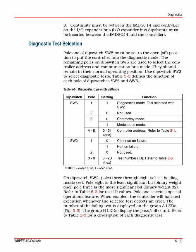
Diagnostics
WBPEEUI230024A0 5 - 11
3. Continuity must be between the IMDSO14 and controller on the I/O expander bus (I/O expander bus dipshunts must be inserted between the IMDSO14 and the controller).
Diagnostic Test Selection
Pole one of dipswitch SW5 must be set to the open (off) posi-tion to put the controller into the diagnostic mode. The remaining poles on dipswitch SW5 are used to select the con-troller address and communication bus mode. They should remain in their normal operating position. Use dipswitch SW2 to select diagnostic tests. Table 5-5 defines the function of each pole of dipswitches SW2 and SW5.
On dipswitch SW2, poles three through eight select the diag-nostic test. Pole eight is the least significant bit (binary weight one); pole three is the most significant bit (binary weight 32). Refer to Table 5-3 for test ID values. Pole one selects a special operations feature. When enabled, the controller will halt test execution whenever the selected test detects an error. The number of the failing test is displayed on the group A LEDs (Fig. 5-3). The group B LEDs display the pass/fail count. Refer to Table 5-3 for a description of each diagnostic test.
Table 5-5. Diagnostic Dipswitch Settings
Dipswitch Pole Setting Function
SW5 1 1 Diagnostics mode. Test selected with SW2.
2 0 Not used.
3 0 Controlway mode.
1 Module bus mode.
4 - 8 0 - 31 (dec)
Controller address. Refer to Table 3-1.
SW2 1 0 Continue on failure.
1 Halt on failure.
2 0 Not used.
3 - 8 0 - 2B (hex)
Test number (ID). Refer to Table 5-3.
NOTE: 0 = closed or on, 1 = open or off.

5 - 12 WBPEEUI230024A0
Diagnostics
LED Display
Group A LEDs (Fig. 5-3) are used during diagnostic mode operation to display test results.
On controller reset, all front panel LEDs turn on. Next, the controller reads the dipswitches, executes the selected test, and displays the result on the group A and B LEDs. Group A LEDs display the test number on LEDs one through six. If LED eight is on, the test failed. The display is latched on for 1/4-second for viewing ease, then the LEDs blank out for about 1/8-second, and the test is repeated. Group B LEDs display a running tally of successes and failures. LEDs one through four tally the passes; LEDs five through eight tally the failures.
If a test fails with the Halt On Failure selected (dipswitch SW2, pole one on), the status LED turns red. The test number that failed is displayed on the group A LEDs.
For group tests (10, 20), each test is run in numerical order. On a failure, group A LED eight flashes and LEDs one through six display the test number that failed. When all tests in the group are done, the error count is incremented and displayed on the group B LEDs.
Figure 5-3. LEDs - Pass/Fail
T01419B
GROUP B LEDs(GREEN)
LED 1
LED 2
LED 3
LED 4
LED 5
LED 6
LED 7
LED 8
PASS COUNT
LSB
LSB
MSB
MSB
FAILURE COUNT
GROUP A LEDs(RED)
LED 1
LED 2
LED 3
LED 4
LED 5
LED 6
LED 7
LED 8
TEST NUMBER
TEST FAILURE
NOT USED

Controller Status Summary
WBPEEUI230024A0 5 - 13
Controller Status SummaryThe controller has a 16-byte controller status record that pro-vides summary flags for error conditions, controller type, and firmware revision level. Table 5-6 shows the fields of the con-troller status report. Table 5-7 lists the definition of each field within the controller status report. Refer to the appropriate HSI instruction for an explanation of how to access the con-troller status report.
Table 5-6. Status Report
ByteBit
7 6 5 4 3 2 1 0
1 ES Mode Type
2 FTX BAC RIO LIO CFG NVF NVI DSS
3 Error code
4 Error code descriptor (1)
5 Error code descriptor (2)
6 ETYPE
7 CWA CWB R1F R2F PF Unused HnetA HnetB
8 Unused
9 RA RB Unused
10 PRI CFC Unused CHK RID RDEXP OCE RDDET
11 Unused Unused Unused SOA RNO Unused Unused Unused
12-13 Unused
14 Controller nomenclature
15 Revision letter (ASCII)
16 Revision number (ASCII)
Table 5-7. Status Report Field Descriptions
Byte FieldField Size or
ValueDescription
1 ES 80 Error summary: 0 = good, 1 = errors.
Mode 60 Controller mode: 00 = configure, 10 = error, 11 = execute.
Type 1F Controller type code: (15)16 = Enhanced status.

5 - 14 WBPEEUI230024A0
Controller Status Summary
2 FTX 80 First time in execute: 0 = no, 1 = yes.
BAC 40 Redundant status: 0 = good, 1 = bad.
RIO 20 Summary remote input status: 0 = good, 1 = bad.
LIO 10 Summary local input status: 0 = good, 1 = bad.
CFG 08 Online configuration changes being made.
NVF 04 Summary NVRAM failure status: 0 = good, 1 = fail.
NVI 02 Summary NVRAM initialized state: 0 = no, 1 = yes.
DSS 01 Digital station status: 0 = good, 1 = bad.
Table 5-7. Status Report Field Descriptions (continued)
Byte FieldField Size or
ValueDescription

Controller Status Summary
WBPEEUI230024A0 5 - 15
3 - 5
Byte 3 is displayed on the front panel LEDs when the controller is in ERROR mode.
Error code 3 4 5
01 01 —02 —03 —FF —
NVRAM error:Write failure.Checksum failure.Bad data.Reset during write.
02 (1) (2) Analog input reference error:(1), (2) = block number of control I/O controller block.
03 (1) (2) Missing I/O controller or expander board:(1), (2) = block number of I/O controller or station.
04 (1) (2) Checkpoint buffer allocation error.(1), (2) = block number of segment block.
05 (1) (2) Configuration error – undefined block:(1), (2) = block number making reference.
06 (1) (2) Configuration error – input data type is incorrect:(1), (2) = block number making reference.
08 (1) (2) Trip block activated:(1), (2) = block number of trip block.
09 — — Segment violation.
0F — — Primary controller has failed and the redundant controller configuration is not current.
10 — — Primary controller has failed and the dynamic RAM data in the redundant controller is not current.
11 — — NVRAM write failure error.
1E (1) (2) Duplicate device label.(1), (2) = block number making reference (FC 221 or
FC 227).
20 — — Program format error - inconsistent format table.
21 00 00FF FEFF FF(1) (2)
File system error:Backup cannot takeover due to uninitialized file system.Directory has not been configured.List of file system free memory is corrupted.(1), (2) = Number of files with errors.
22 (1) (2) Invoke C error: (1), (2) = block number making reference.
24 (1) (2) C program stack overflow:(1), (2) = block number making reference.
2A (1) (2) Not enough memory: (1), (2) = block number making ref.
Table 5-7. Status Report Field Descriptions (continued)
Byte FieldField Size or
ValueDescription

5 - 16 WBPEEUI230024A0
Controller Status Summary
6 ETYPE 1F Enhanced controller type = (24)16 = Controller.
7 CWA 80 Controlway bus A failure: 0 = good, 1 = fail.
CWB 40 Controlway bus B failure: 0 = good, 1 = fail.
R1F 20 Redundancy link channel 1 failure: 0 = good, 1 = fail.
R2F 10 Redundancy link channel 2 failure: 0 = good, 1 = fail.
— — Unused.
— — Unused.
HnetA 02 Hnet channel A failure: 0 = good, 1 = fail.
HnetB 01 Hnet channel B failure: 0 = good, 1 = fail.
8 — — Unused.
9 RA 80 Hnet channel A relay fault: 0 = good, 1 = fail.
RB 40 Hnet channel B relay fault: 0 = good, 1 = fail.
— — Unused.
— — Unused.
— — Unused.
— — Unused.
— — Unused.
— — Unused.
Table 5-7. Status Report Field Descriptions (continued)
Byte FieldField Size or
ValueDescription

Controller Status Summary
WBPEEUI230024A0 5 - 17
10 PRI 80 Controller is primary versus redundant; set to 1 in the pri-mary controller.
CFC 40 Configuration current (latched until redundant is reset). Set when LED 7 is enabled (1 = on or blinking) on the redundant controller.
— — Unused.
CHK 10 Redundant has completed checkpointing (latched until redundant is reset). Always set to 0 on the primary con-troller. Follows LED 8 (1 = on or blinking) on the redun-dant controller.
RID 08 Redundancy ID. Follows setting of redundancy ID pole on the dipswitch.
RDEXP 04 Redundancy expected. Always set to 1 on the redundant controller. Follows state of FC 90, specification S3, ones digit on the primary controller.
OCE 02 Online configuration is enabled. Follows setting of online configuration enable pole on dipswitch.
RDDET 01 Redundancy detected (latched until controller is reset or it changes from redundant to primary or primary to redundant). Set to 1 when a properly configured redun-dant controller is detected.
11 — — Unused.
— — Unused.
— — Unused.
SOA 10 Status output alarm. Indicates the status of the system +24 volt power and the block I/O power (logic and field power for a single cabinet). 0 = OK, 1 = alarm.
RNO 08 Redundancy NVRAM overrun (latched indication). Set to 1 in primary controller if NVRAM checkpoint overruns have occurred. NVRAM checkpoint overruns cause the primary controller to reset the redundant controller.
— — Unused.
— — Unused.
— — Unused.
12-13 — 00 Unused.
14 — FF Controller nomenclature: (06)16 = BRC-300.
Table 5-7. Status Report Field Descriptions (continued)
Byte FieldField Size or
ValueDescription

5 - 18 WBPEEUI230024A0
Card Edge Connectors
Card Edge ConnectorsThe controller has two card edge connectors and one high den-sity connector that provide it with power and I/O channels.
• Tables 5-8, 5-9, 5-10, 5-11, and 5-12 list the controller card edge connector pin assignments.
• Tables 5-13, 5-14, 5-15, and 5-16 list the PBA connector pin assignments.
NOTE: The pin assignments for the PBA connector P5 are identical to the pin assignments for the controller connector P3 listed in Table 5-10.
15 — FF Revision letter (in ASCII code), for example, (47)16 = G.
16 — FF Revision number (in ASCII code), for example, (30)16 = 0.
Table 5-7. Status Report Field Descriptions (continued)
Byte FieldField Size or
ValueDescription
Table 5-8. P1 Pin Assignments (Controller)
Pin Signal Pin Signal
1 5 VDC 2 5 VDC
3 Unused 41 -30 VDC or Controlway/module bus B
5 Common 6 Common
7 Unused 8 Unused
9 Power fail interrupt 10 Unused
11 Controlway/module bus A 12 Unused
NOTE:1. This pin connects the controller to -30 VDC when it is used in -30 VDC Network 90 systems. When the controller is used in newer Network 90, INFI 90 OPEN, and Symphony systems, this pin connects the controller to the redundant Controlway channel.
Table 5-9. P2 Pin Assignments (Controller)
Pin Signal Pin Signal
1 Data bit 1 2 Data bit 0
3 Data bit 3 4 Data bit 2
5 Data bit 5 6 Data bit 4

Card Edge Connectors
WBPEEUI230024A0 5 - 19
7 Data bit 7 8 Data bit 6
9 Bus clock - BCLK 10 Sync
11 Unused 12 Unused
NOTE: All data bits are true low.
Table 5-10. P3 Pin Assignments (Controller)1,2
Pin Signal Pin Signal
1 Common 42 Request to send A (-)4
2 Digital output 13 43 Request to send A (+)4
25 5 VDC 44 Request to send B (-)4
26 DCS/IISAC01 link A (-) 45 Request to send B (+)4
27 DCS/IISAC01 link A (+) 46 SOA3
28 DCS/IISAC01 link B (-) 47 5 VDC
29 DCS/IISAC01 link B (+) 48 Hnet transmit data A
30 Receive data A (-) 49 Hnet receive data A
31 Receive data A (+)4 50 Hnet transmit clock A
32 Receive data B (-)4 51 Hnet receive clock A
33 Receive data B (+)4 52 Hnet transmit data B
34 Clear to send A (-)4 53 Hnet receive data B
35 Clear to send A (+)4 54 Hnet transmit clock B
36 Clear to send B (-)4 55 Hnet receive clock B
37 Clear to send B (+)4 56 Hnet transmit enable A3
38 Transmit data A (-)4 57 Hnet transmit enable B3
39 Transmit data A (+)4 58 PBA/Hnet relay A
40 Transmit data B (-)4 59 PBA/Hnet relay B
41 Transmit data B (+)4 60 Common
NOTES:1. PBA adaptor connector P5 pin assignments listed in Table 5-16 are identical to the pin assign-ments listed in this table.2. Harmony I/O Hood Connector P5 pin assignments listed in Table 5-17 are identical to the pin assignments listed in this table.3. Data bit or signal is true low.4. Serial signal from the RS-232-C DUART.
Table 5-9. P2 Pin Assignments (Controller) (continued)
Pin Signal Pin Signal

5 - 20 WBPEEUI230024A0
Card Edge Connectors
Table 5-11. P4 Pin Assignments (Controller)
PinSignal
DTE DCE
2 Receive data Transmit data
3 Transmit data Receive data
7 Request to send Clear to send
8 Clear to send Request to send
9 Ground Ground
Table 5-12. P7 Pin Assignments (Controller)
Pin Signal Pin Signal
1 Common 14 Common
2 Common 15 Busy2-
3 CLK1+ 16 Busy2+
4 CLK1- 17 Common
5 Common 18 Common
6 Common 19 D2-
7 D1+ 20 D2+
8 D1- 21 Common
9 Common 22 Common
10 Common 23 CLK2-
11 Busy1+ 24 CLK2+
12 Busy1- 25 Common
13 Common 26 Common
Table 5-13. P1 Pin Assignments (PBA)
Pin Signal Pin Signal
1 Common 2 Hnet channel 1C
3 5 VDC 4 Hnet channel 1D
5 5 VDC 6 Status output alarm 1
7 Common 8 Common
9 Status output alarm 2 10 5 VDC
11 Hnet channel 2D 12 5 VDC
13 Hnet channel 2C 14 Common
NOTE: All signals are true low.

Card Edge Connectors
WBPEEUI230024A0 5 - 21
Table 5-14. P3 Pin Assignments (PBA)
Pin Signal Pin Signal
1 IISAC01/DCS link A (–) 16 IISAC01/DCS link A (+)
2 IISAC01/DCS link B (–) 17 IISAC01/DCS link B (+)
3 - 6 NC 18 - 21 NC
7 Receive data A (–) 22 Receive data A (+)
8 Receive data B (–) 23 Receive data B (+)
9 Clear to send A (–) 24 Clear to send A (+)
10 Clear to send B (–) 25 Clear to send B (+)
11 Transmit data A (–) 26 Transmit data A (+)
12 Transmit data B (–) 27 Transmit data B (+)
13 Request to send A (–) 28 Request to send A (+)
14 Request to send B (–) 29 Request to send B (+)
15 Digital output 1 (–) 30 Digital output 1 (+)
Table 5-15. P4 Pin Assignments (PBA)2
Pin Signal Pin Signal
1 Common 21 Red1 parity1
2 Red2 busy1 22 Common
3 Common 23 Red1 data0
4 Red2 BCLK1 24 Red1 data1
5 Common 25 Red1 data2
6 Red2 parity1 26 Red1 data3
7 Common 27 Red1 data4
8 Red2 data0 28 Red1 data5
9 Red2 data1 29 Red1 data6
10 Red2 data2 30 Red1 data7
11 Red2 data3 31 Common
12 Red2 data4 32 NC
13 Red2 data5 33 NC
14 Red2 data6 34 NC
15 Red2 data7 35 NC
16 Common 36 NC
17 Red1 busy1 37 NC
18 Common 38 NC

5 - 22 WBPEEUI230024A0
Card Edge Connectors
19 Red1 BCLK 1 39 NC
20 Common 40 NC
NOTE:1. Data bit or signal is true low.2. P4 connector of (PBA) is not utilized by the controller.
Table 5-16. P5 Pin Assignments (PBA)
Pin Signal Pin Signal
1 Common 31 Receive data A (+)2
2 Digital output 11 32 Receive data B (-)2
3 Red1 data73 33 Receive data B (+)2
4 Red1 data63 34 Clear to send A (-)2
5 Red1 data53 35 Clear to send A (+)2
6 Red1 data43 36 Clear to send B (-)2
7 Red1 data33 37 Clear to send B (+)2
8 Red1 data23 38 Transmit data A (-)2
9 Red1 data13 39 Transmit data A (+)2
10 Red1 data03 40 Transmit data B (-)2
11 Red1 parity1, 3 41 Transmit data B (+)2
12 Red1 BCLK1, 3 42 Request to send A (-)2
13 Red1 busy1, 3 43 Request to send A (+)2
14 Red2 data73 44 Request to send B (-)2
15 Red2 data63 45 Request to send B (+)2
16 Red2 data53 46 SOA1
17 Red2 data43 47 5 VDC
18 Red2 data33 48 Hnet transmit data A
19 Red2 data23 49 Hnet receive data A
20 Red2 data13 50 Hnet transmit clock A
21 Red2 data03 51 Hnet receive clock A
22 Red2 parity1, 3 52 Hnet transmit data B
23 Red2 BCLK1, 3 53 Hnet receive data B
24 Red2 busy1, 3 54 Hnet transmit clock B
25 5 VDC 55 Hnet receive clock B
26 DCS/IISAC01 link A (-) 561 Hnet transmit enable A
Table 5-15. P4 Pin Assignments (PBA)2 (continued)
Pin Signal Pin Signal

Card Edge Connectors
WBPEEUI230024A0 5 - 23
27 DCS/IISAC01 link A (+) 571 Hnet transmit enable B
28 DCS/IISAC01 link B (-) 58 PBA/Hnet relay A
29 DCS/IISAC01 link B (+) 59 PBA/Hnet relay B
30 Receive data A (-) 60 Common
NOTES:1. Data bit or signal is true low.2. Serial signal from the RS-232-C DUART.3. Redundancy link signals on P5 (PBA) and P5 (hood connection assembly) are not utilized by the controller.
Table 5-17. P5 Pin Assignments (Hood Connection Assembly)
Pin Signal Pin Signal
1 Common 31 Receive data A (+)2
2 Digital output 11 32 Receive data B (-)2
3 Red1 data73 33 Receive data B (+)2
4 Red1 data63 34 Clear to send A (-)2
5 Red1 data53 35 Clear to send A (+)2
6 Red1 data43 36 Clear to send B (-)2
7 Red1 data33 37 Clear to send B (+)2
8 Red1 data23 38 Transmit data A (-)2
9 Red1 data13 39 Transmit data A (+)2
10 Red1 data03 40 Transmit data B (-)2
11 Red1 parity1, 3 41 Transmit data B (+)2
12 Red1 BCLK1, 3 42 Request to send A (-)2
13 Red1 busy1, 3 43 Request to send A (+)2
14 Red2 data73 44 Request to send B (-)2
15 Red2 data63 45 Request to send B (+)2
16 Red2 data53 46 SOA1
17 Red2 data43 47 5 VDC
18 Red2 data33 48 Hnet transmit data A
19 Red2 data23 49 Hnet receive data A
20 Red2 data13 50 Hnet transmit clock A
21 Red2 data03 51 Hnet receive clock A
22 Red2 parity1, 3 52 Hnet transmit data B
23 Red2 BCLK1, 3 53 Hnet receive data B
Table 5-16. P5 Pin Assignments (PBA) (continued)
Pin Signal Pin Signal

5 - 24 WBPEEUI230024A0
Card Edge Connectors
24 Red2 busy1, 3 54 Hnet transmit clock B
25 5 VDC 55 Hnet receive clock B
26 DCS/IISAC01 link A (-) 561 Hnet transmit enable A
27 DCS/IISAC01 link A (+) 571 Hnet transmit enable B
28 DCS/IISAC01 link B (-) 58 PBA/Hnet relay A
29 DCS/IISAC01 link B (+) 59 PBA/Hnet relay B
30 Receive data A (-) 60 Common
NOTES:1. Data bit or signal is true low.2. Serial signal from the RS-232-C DUART.3. Redundancy link signals on P5 (PBA) and P5 (hood connection assembly) are not uti-lized by the controller.
Table 5-17. P5 Pin Assignments (Hood Connection Assembly) (continued)
Pin Signal Pin Signal
WBPEEUI230024A0 6 - 1
Section 6Maintenance
IntroductionThe reliability of any stand-alone product or control system is affected by the maintenance of the equipment. ABB recom-mends that all equipment users practice a preventive mainte-nance program that will keep the equipment operating at an optimum level.
This section presents procedures that can be performed on-site. These preventive maintenance procedures should be used as guidelines to assist you in establishing good preven-tive maintenance practices. Select the minimum steps required to meet the cleaning needs of your system.
Personnel performing preventive maintenance should meet the following qualifications:
• Should be qualified electrical technicians or engineers that know the proper use of test equipment.
• Should be familiar with the controller, have experience working with process control systems, and know what pre-cautions to take when working on live AC systems.
Preventive Maintenance ScheduleTable 6-1 is the preventive maintenance schedule for the con-troller. The table lists the preventive maintenance tasks in groups according to their specified maintenance interval. Some tasks in Table 6-1 are self-explanatory. Instructions for tasks that require further explanation are covered under Preventive Maintenance Procedures.
NOTE: The preventive maintenance schedule is for general purposes only. Your application may require special attention.
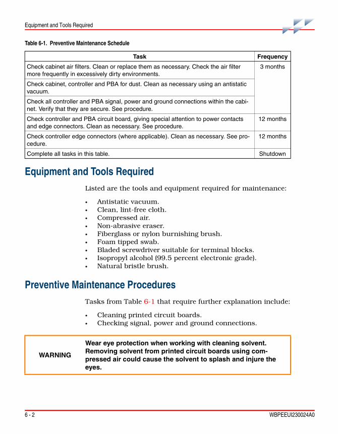
6 - 2 WBPEEUI230024A0
Equipment and Tools Required
Equipment and Tools Required
Listed are the tools and equipment required for maintenance:
• Antistatic vacuum.• Clean, lint-free cloth.• Compressed air.• Non-abrasive eraser.• Fiberglass or nylon burnishing brush.• Foam tipped swab.• Bladed screwdriver suitable for terminal blocks.• Isopropyl alcohol (99.5 percent electronic grade).• Natural bristle brush.
Preventive Maintenance ProceduresTasks from Table 6-1 that require further explanation include:
• Cleaning printed circuit boards.• Checking signal, power and ground connections.
Table 6-1. Preventive Maintenance Schedule
Task Frequency
Check cabinet air filters. Clean or replace them as necessary. Check the air filter more frequently in excessively dirty environments.
3 months
Check cabinet, controller and PBA for dust. Clean as necessary using an antistatic vacuum.
Check all controller and PBA signal, power and ground connections within the cabi-net. Verify that they are secure. See procedure.
Check controller and PBA circuit board, giving special attention to power contacts and edge connectors. Clean as necessary. See procedure.
12 months
Check controller edge connectors (where applicable). Clean as necessary. See pro-cedure.
12 months
Complete all tasks in this table. Shutdown
WARNING
Wear eye protection when working with cleaning solvent. Removing solvent from printed circuit boards using com-pressed air could cause the solvent to splash and injure the eyes.

Preventive Maintenance Procedures
WBPEEUI230024A0 6 - 3
Printed Circuit Board Cleaning
There are several circuit board cleaning procedures in this sec-tion. These procedures cover circuit board cleaning and washing, cleaning edge connectors and circuit board laminate between edge connectors. Use the procedures that meet the needs of each circuit board. Remove all dust, dirt, oil, corro-sion or any other contaminant from the circuit board.
Do all cleaning and handling of the printed circuit boards at static safe work stations. Observe the steps listed in Special Handling in Section 3 when handling printed circuit boards.
General Cleaning and Washing
If the printed circuit board needs minor cleaning, remove dust and residue from the printed circuit board surface using clean, dry, filtered compressed air or an antistatic field service vacuum cleaner. Another method of washing the printed cir-cuit board is:
1. Clean the printed circuit board by spraying it with isopro-pyl alcohol (99.5 percent electronic grade) or wiping the circuit board with a foam tipped swab wetted in isopropyl alcohol.
2. When the circuit board is clean, remove excess solvent by using compressed air to blow it free of the circuit board.
Edge Connector Cleaning
To clean edge connector contacts:
1. Use a solvent mixture of 80 percent isopropyl alcohol (99.5 percent electronic grade) and 20 percent distilled water.
2. Soak a lint-free cloth with the solvent mixture.
3. Work the cloth back and forth parallel to the edge connec-tor contacts.
4. Repeat with a clean cloth soaked with the solvent mixture.
5. Dry the edge connector contact area by wiping with a clean lint-free cloth.

6 - 4 WBPEEUI230024A0
Preventive Maintenance Procedures
To clean tarnished or deeply stained edge connector contacts:
1. Use a non-abrasive eraser to remove tarnish or stains. Fiberglass or nylon burnishing brushes may also be used.
2. Minimize electrostatic discharge by using the 80/20 iso-propyl alcohol/water solution during burnishing.
3. Do not use excessive force while burnishing. Use only enough force to shine the contact surface. Inspect the edge connector after cleaning to assure no loss of contact surface.
Checking Connections
Check all signal wiring, power and ground connections within the cabinet to verify their integrity. When checking connec-tions, always turn a screw, nut or other fastening device in the direction to tighten only. If the connection is loose, it will be tightened. If the connection is tight, the tightening action will verify that it is secure. There must not be any motion done to loosen the connection.
NOTE: Power to the cabinet must be off while performing this task.
Verify that all cable connections are secure.

WBPEEUI230024A0 7 - 1
Section 7Repair and Replacement
IntroductionRepair procedures are limited to controller replacement. If the controller or PBA fails, remove and replace it with another. Verify that firmware revision levels match and that the replace-ment controller switch and jumper settings are the same as those of the failed controller.
Replacement controllers and PBAs must be supplied only by ABB or an authorized ABB sales representative.
Controller ReplacementObserve the steps under Special Handling in Section 3 when handling controllers.
NOTES: 1. Do not remove a controller or PBA under power unless the stop/reset switch on the controller has been depressed once and the controller has halted (status LED is red and group A LEDs one through six are on). This procedure must be followed when removing a controller or PBA from a redundant configu-ration. An operational primary controller/PBA must halt operation before control passes to the redundant controller/PBA.
2. Do not replace any BRC-200 with a BRC-300.
3. Do not replace a redundant BRC-100 with a BRC-300 unless the primary BRC-100 is replaced with a BRC-300 as well. The redundancy links of the BRC-100 are not compatible with the redundancy links of the BRC-300.
4. For most applications, it is okay to replace a BRC-100 with a BRC-300. For the BRC-300 G.0 firmware, the following functions are not supported:Batch 90 (future release of firmware will support this function), simulation sup-port, user defined function codes (UDF), and CLIF. Do not replace a BRC-100 with a BRC-300 for these specific functions.
To replace a controller:
1. If the controller is redundant, first remove the redundancy link cable.

7 - 2 WBPEEUI230024A0
PBA Replacement
2. Turn the two latching screws on the controller faceplate ½-turn either way to release it.
3. Grasp the screws and pull out the controller from the MMU.
4. Set all dipswitches and jumpers on the replacement con-troller to match the settings of the removed controller.
NOTE: Dipswitch SW3 is not used. Set all poles on dipswitch SW3 to closed (on).
5. Hold the controller by the faceplate and slide it into its assigned MMU slot. Push until the rear edge of the controller is firmly seated in the PBA connector (for controllers controlling Harmony block I/Os via Hnet) or the backplane connector (for controllers controlling rack I/O controllers via the I/O expander bus).
6. Turn the two latching screws on both controllers ½-turn either way to lock the controller in place. The controller is locked into the MMU when the open end of the slots on the latching screws faces the center of the controller faceplate.
7. If the controller is redundant, connect the redundancy cable between the faceplate of the primary controller to the faceplate of the redundant controller. The cable is keyed and will insert in only one orientation.
PBA ReplacementObserve the steps under Special Handling in Section 3 when handling a PBA.
NOTES: 1. Do not remove a controller or PBA under power unless the stop/reset switch on the controller has been depressed once and the controller has halted (status LED is red and group A LEDs one through six are on). This procedure must be followed when removing a controller or PBA from a redun-dant configuration. An operational primary controller/PBA must halt operation before control passes to the redundant controller/PBA.

PBA Replacement
WBPEEUI230024A0 7 - 3
2. When installing a PBA-200, it may be necessary to remove an existing PBA-100 (previous release). It is recommended that the existing mounting bracket used with the PBA-100 be left alone.
To replace a PBA:
1. Turn the two latching screws on the controller faceplate ½-turn either way to release it.
2. Grasp the screws and pull the controller from its P5 con-nection on the PBA. It is not necessary to completely remove the controller from the MMU.
3. Disconnect the redundant processor bus adapter cable to Harmony mounting column from the P1 connector on the PBA.
4. If the auxiliary serial channels or analog control stations are being used, disconnect the TU cable from the P3 connector on the PBA.
5. Remove the PBA.
6. If the PBA being replaced has a terminator, remove the ter-minator from the existing PBA and install it on the replace-ment PBA.
NOTES: 1. The terminator must stay attached to the cable.
2. A terminator should be installed on the last PBA in a redundant configura-tion.
7. Insert the replacement PBA into position on the MMU.
8. Connect the redundant processor bus adapter cable to Harmony mounting column to the P1 connector on the PBA.
9. If the auxiliary serial channels or analog control stations are being used, connect the TU cable to the P3 connector on the replacement PBA.
WARNING
Disconnect power before removing a PBA-100 mounting bracket on the MMU backplane. Failure to do so will result in contact with cabinet areas that could cause severe or fatal shock.

7 - 4 WBPEEUI230024A0
PBA Replacement
10. Hold the controller by the faceplate and slide it into its assigned MMU slot.
11. Turn the two latching screws on the controller faceplate ½-turn either way to lock it.

WBPEEUI230024A0 8 - 1
Section 8Spare Parts List
PartsOrder parts without commercial descriptions from the nearest ABB sales office. Contact ABB for help determining the quan-tity of spare parts to keep on hand for your particular system. Tables 8-1, 8-2, and 8-3 list controller related parts.
Table 8-1. Miscellaneous Nomenclatures
1 2 3 4 5 6 7 8 9 10 11 12 13 14 15 16 17
N T M P 0 1 _ _ _ _ _ _ _ _ _ _ _ Multifunction processor termination unitP - H A - M S C - T E R 1 0 0 0 0 Hnet terminatorP - H A - R E P - R F O 1 0 0 0 0 Harmony RepeaterP - H C - B R C - 3 0 0 0 0 0 0 0 Harmony BRC-300P - H C - B R C - P B A 2 0 0 0 0 Processor bus adapter
Table 8-2. Cable Nomenclatures
1 2 3 4 5 6 7 8 9 10 11 12 13 14 15 16 17
N K S E 0 1 _ _ _ _ _ _ _ _ _ _ _ Serial extension cable (PVC)N K S E 1 1 _ _ _ _ _ _ _ _ _ _ _ Serial extension cable (non-PVC)N K T U 0 1 _ _ _ _ _ _ _ _ _ _ _ Termination unit cable (PVC)N K T U 1 1 _ _ _ _ _ _ _ _ _ _ _ Termination unit cable (non-PVC)
P - M K - H R M - P B A 1 0 0 0 _ Redundant processor bus adapter cable to single mounting columnCable length:
x 1 to 4 for 1.0 to 4.0 m (3.3 to 13 ft.) – end mounted PBA connectors
P - M K - H R M - P B A 1 T 0 0 _ Redundant processor bus adapter cable to dual mounting columnCable length:
x 2 to 4 for 2.0 to 4.0 m (6.6 to 13 ft.) – center mounted PBA connectors
P - M K - H R M - B R C 3 0 0 0 A Redundancy link cable for two BRC-300 controllers
Table 8-3. Miscellaneous Parts
Description Part Number
Jumper 1946984A1

WBPEEUI230024A0
WBPEEUI230024A0 A - 1
Appendix AOnline Configuration
IntroductionUsing online configuration in conjunction with redundant con-trollers enables making configuration changes without affect-ing the primary controller or interrupting the control process.
NOTE: The term redundant controller always refers to the original redundant controller, and the term primary controller always refers to the original primary controller. When the roles are reversed, the statuses of the controllers are carefully noted.
Composer provides functions to guide the user through the online configuration process. These functions use the enhanced status information contained in byte ten of the con-troller status report. Using Composer for online configuration is the preferred method. The information in this appendix explains how to manually perform online configuration.
In redundant controller configurations, the primary controller executes the process control logic while the redundant control-ler tracks the configuration of the primary. Online configura-tion allows removing the redundant controller from the tracking mode and making configuration changes, without interrupting the process control operation of the primary con-troller. It also supports conventional offline changes. When the redundant controller has been reconfigured, it can assume control with the new configuration while the original primary controller assumes the redundant role.
During startup of the new configuration in the redundant con-troller, it uses the current values of all process outputs in the primary controller. This feature permits bumpless transfer of control to the new configuration.
SetupSet position two on the options dipswitch (SW2) of the redun-dant and primary controllers to the open position to enable online configuration. This provides communication access to

A - 2 WBPEEUI230024A0
Setup
the backup controller at an address one higher than what is set on the address switch (SW5).
Online configuration of redundant controllers requires two consecutive Controlway addresses to be reserved (n and n+1; where n is the primary address, n+1 is the redundant). Opera-tion
In some user applications, controllers are remotely located, and the operator is unable to view the group A LEDs. In these applications, the data from the redundant controller status byte must be used. This appendix shows both the state of LEDs seven and eight as well as the contents of the redundant controller status byte (specifically bits seven, six, three and one). For each step of the online configuration process, both the contents of the status byte as well as the state of group A LEDs seven and eight (Fig. 4-1) are indicated in the margin.
A workstation running Conductor software and a computer running Conductor software are examples of HSI platforms that can be used to acquire controller status reports. Refer to the instruction for the interface being used for the procedures to call up status reports.
Table A-1 shows the symbols used in this appendix.
WARNING
Do not reset a controller before the LEDs or controller status byte indicate that the controller is available. Resetting a con-troller prematurely could result in unpredictable operation, loss of output data, or loss of control.
Table A-1. Legend of Symbols
Description Primary Redundant
Controller address n n+1
Redundant controller status byte Bit1
7 6 5 4 3 2 1 00 1 x x 0 x 0 x
Bit1
7 6 5 4 3 2 1 01 0 x x 1 x 0 x

Setup
WBPEEUI230024A0 A - 3
Redundant Cycle
Table A-2 and Figure A-1 illustrate the redundant cycle.
LEDs 7 and 8. In the following tables, LED 7 is on top, LED 8 is on bottom.
onoffblinking
NOTE: x = ignore, 1 = bit set, 0 = bit not set.bit 7 = first time in execute (most significant bit (MSB))bit 6 = redundant controller status badbit 3 = online configuration changes being madebit 1 = NVRAM default configuration
Table A-1. Legend of Symbols (continued)
Description Primary Redundant
Table A-2. Redundant Cycle
Primary Redundant Step
n00xx0x0x
n+110xx0x0x
1. Save a copy of the current configuration. This enables it to be easily restored if needed.
n01xx0x0x
n01xx0x0x
n+100xx0x0x
n+100xx1x0x
2. Place the redundant controller in configure mode.
The green LED of the redundant controller blinks indicating configure mode. The controller status also indicates configure mode. Configuration commands to the redundant controller are sent to the address of the pri-mary controller plus one (n+1). The primary controller now indicates that the redundant controller is not available for automatic failover. Bit 6 indi-cates this condition.
To return to Step 1 without making any changes, place the redundant controller in execute mode and reset it after LED 8 illuminates or the pri-mary status indicates 00xx0x0x. Resetting a controller causes all the LEDs on it to light momentarily before returning to normal status.
When changes are being made to the redundant controller, LED 7 blinks and bit 3 of the redundant controller is set indicating that the configura-tions of the redundant and primary controllers do not match. If these changes to the configuration are incorrect, return to Step 1 by an initialize of the redundant controller NVRAM while it is in configure mode.

A - 4 WBPEEUI230024A0
Setup
n01xx0x0x
n+100xx1x0x
3. When an error exists in the new configuration, the redundant controller enters error mode when initiating a transfer to execute mode command. Return to configure mode to fix the error. The green LED of the redundant controller blinks to indicate it is in the error or configure mode. The first byte of the controller status also indicates the mode. Redundant control-ler LED 7 blinks and bit 3 of the controller status is set to indicate that configuration differences exist between the primary and redundant.
n01xxxx0x
__ During steps 2, 3 and 4 of online configuration, the redundant controller is not capable of taking over as primary controller because of the incom-plete configuration or incomplete checkpoint data. If there is a complete failure of the primary controller, the online configured redundant controller will takeover as the primary controller, but will be in error mode. All Har-mony block I/O and I/O expander bus controllers will enter their config-ured stall states.
n01xx0x0x
n+100xx1x0x
4. The redundant controller can now be placed in execute mode provided no errors remain in the new configuration.
Additional configuration changes can be made by entering configure mode (Step 2). If no changes have been made, a redundant controller reset returns the redundant controller to the state of Step 1. If changes have been made, the redundant controller must be put into configure mode and initialized to get to the state of Step 1.
NOTE: The redundant cycle step transition 3 to 4 occurs automatically after a successful Step 3 redundant controller execute. The transaction completion time depends on the controller configuration.
n01xx0x0x
n+110xx1x0x
5. When the checkpoint data for the old configuration is received from the primary controller, the reconfigured redundant controller can assume the role of the primary controller if a failure is detected in the old configuration (Step 8). However, the primary controller still indicates that no redundant controller is available when the configuration is different.
Additional configuration changes can be made by entering configure mode (Step 2). If no changes have been made, a redundant controller reset returns the redundant controller to the state of Step 1. If changes have been made, the redundant controller must be put into configure mode and initialized to get to the state of Step 1.
n01xx0x0x
n+100xx1x0x
6. After the changes have been made, tell the reconfigured redundant controller to assume the role of the primary controller by pressing and releasing the stop/release button on the redundant controller 2 times. The first time stops the controller; the second time resets the controller. The redundant controller comes up in execute mode with the configuration marked as valid.
Table A-2. Redundant Cycle (continued)
Primary Redundant Step

Setup
WBPEEUI230024A0 A - 5
n01xx0x0x
n+110xx1x0x
7. Redundant cycle step transitions 5 to 6 to 7 to 8 occur automatically after the Step 5 redundant controller reset. The time it takes to complete these transitions depends on controller configuration. The status indi-cated in cycles 5, 6 and 7 may not be seen depending on the actual step transition times. The important status to wait on is indicated by Step 8.
After the checkpoint data is updated, the redundant controller is ready to take over the duties of the primary controller.
n01xx0x0x
n+111xx1x0x
8. The redundant controller requests the primary controller to shut down and assume the role of a hot redundant controller (n+1). The redundant controller waits to act as the primary controller (n). A hot redundant con-troller retains the old configuration and control data and is ready to assume control if an error is detected in the new configuration.
n+101xx0x0x
n01xx1x0x
9. The primary controller has removed the bus clock (BUSCLK) and acts as a hot redundant controller (n+1). The reconfigured redundant control-ler is now serving as the primary controller (n).
NOTE: In this phase of the online configuration, the backup is not tracking tuning or other changes. This transition phase should be concluded as quickly as feasible to return to normal hot standby operation.
Before proceeding to the following commands, insure that LED/controller status is as shown in Step 8. To return to Step 4, reset the redundant con-troller (n). This allows correcting a bad configuration.
The primary controller (n+1) must be reset at this point for the online con-figuration cycle to complete. Resetting the primary controller (n+1), cur-rently acting as the hot redundant controller, tells it to get a copy of the new configuration.
n+110xx0x0x
n00xx0x0x
10. After the redundant controller copies the new configuration into the primary controller, the cycle is complete. The redundant controller is now serving as the primary controller (n) while the primary handles the redun-dant controller role (n+1). The LED combination and controller status is the opposite of Step 1, indicating the role reversal.
Table A-2. Redundant Cycle (continued)
Primary Redundant Step

A - 6 WBPEEUI230024A0
Setup
Primary Cycle
Table A-3 and Figure A-2 illustrate the primary cycle. The step numbers in this cycle correspond to the states of Figure A-2. This information is provided for status purposes. Follow the redundant cycle steps to perform online configuration.
Figure A-1. Redundant Cycle
C H E C K P O IN T DATAIS C O M P LE TE
5R E DU N D.
E X T
4R E DU N D.
E X T
2RE D U N D.
C FG
1R E D UN D.
E X T
3R E DU N D.
E RR
3AP R IM ARY
ER R
10P R IM ARY
E X T
9P R IM ARY
E X T
8R ED U N D.
E X T
7RE D U N D.
E XT
6R E DU N D.
E X T
T01739B
C H E C K P O IN TDATA IS
C O M P LE T E
R E S E T(C H A N G E S M A D E)
R EQ U ES TS H U T D OW N O F
P R IM A RY
R ES E T (C O N FIG U R AT IO N N OT C O P IE D )
C O N FIG U R AT IO NIS C O P IE D TOTH E R E D U N D.
R E S E T(N O C H A N G E )
E X T
E X T
C F G
C F G
C F G
IN ITIA LIZ EE ER O M
C FG TH E N E X T
L E G E N D :E X T = E X EC U TE M O D EC F G = C O N FIG U R AT IO N M O D EE R R = E R R O R M O D E
S T EPR O LEM O D E
= L O S S O F B OT H H N E T C H A N N E LS O R EX PA N D E R B U S C LO C K
I/O IN T E R FAC E
I/O IN TE R FAC EI/O IN T ER FAC E
I/O IN TE R FAC E I/O IN T ER FAC E
I/O IN T E R FAC E
I/O IN TE R FAC E

Setup
WBPEEUI230024A0 A - 7
Table A-3. Primary Cycle
Primary Redundant Step
n01xx0x0x
n+110xx1x0x
1. The primary controller is actively controlling the process. This repre-sents the same juncture as Step 4 of the redundant cycle.
n+101xx0x0x
n11xx1x0x
2. When the shutdown request is received from the redundant controller (Step 7 of the redundant cycle), the primary controller stops executing and removes the bus clock (BUSCLK).
n+101xx0x0x
n01xx1x0x
3. The primary controller is now acting as the hot redundant controller (n+1). All old configuration and block output information remains intact from when it is shut down in Step 2. If the new configuration is not operat-ing as expected, the primary controller, currently acting as the hot redun-dant controller (n+1), can take control using the old configuration and block output information (returns to Step 1).
n+100xx0x0x
n00xx1x0x
4. Resetting the primary controller (n+1), currently acting as the hot redundant controller, directs it to get a copy of the new configuration (Step 8 of the redundant cycle).
n+110xx0x0x
n00xx0x0x
5. When the new configuration has been copied, the redundant controller has completed its cycle and is now serving as the primary controller.
n+110xx0x0x
n00xx0x0x
6. After the checkpoint data is complete, the primary controller is now serving as the redundant controller and is ready to take over the control process with the updated configuration. The primary cycle is complete. This represents the same juncture as Step 10 of the redundant cycle.

A - 8 WBPEEUI230024A0
Setup
Figure A-2. Primary Cycle
S H U TD OW NR E Q U E S TED
C O P Y TH EP R IM ARY ’S
C O N FIG U R ATIO N
T02466B
S H U TD O W NC O M P LE TE
R E SE TC H E C K PO IN T DATAIS C O M PLETE
3H OT
R E D U N D.EX T
2PR IM A RY
E X T
1P R IM A RY
E X T
5R E D U ND.
E X T
6R E D U N D.
EX T
4R E D U N D.
E X T
I/O IN T ER FAC E
I/O IN TE R FAC E
S TE PR O LEM O D E
LE G EN D :EX T = E XE C U TE M O D EI/O IN TER FAC E = LO SS O F B OTH H N E T C H AN N E LS O R E XPA N D ER BU S C LO C K
WBPEEUI230024A0 B - 1
Appendix BNTMP01 Termination Unit
DescriptionThe controller and PBA combination uses an NTMP01 TU to connect two auxiliary serial I/O ports and IISAC01 Analog Control Stations. Jumpers on the NTMP01 TU configure the two RS-232-C ports for DTE or DCE. One of the RS-232-C ports can be configured as an RS-485 port. Refer to the NTMP01 instruction for complete information on applications.
• Figures B-1, B-2, B-3, and B-4 show the jumper configura-tions for jumpers J1 and J2.
• Figure B-5 shows the jumper configurations for jumpers J3 through J10.
• Figure B-6 shows the NTMP01 connector assignments and jumper locations.
NOTES: 1. Jumpers J11 and J12 are storage posts for extra jumpers.
2. Jumper J13 is normally set with pins one and two connected. This con-nects the cable shielding pin of connector P7 to chassis ground.
3. Jumper J18 configures the terminal serial port for RS-485 operation when pins two and three are connected and connector P7 is used instead of connec-tor P5.

B - 2 WBPEEUI230024A0
Description
Figure B-1. DTE Jumper Configuration (NTMP01)
Figure B-2. DCE Jumper Configuration (NTMP01)
T 01 35 5 A
J1 AN D J2
1
11
3
9
5
7
4
10
6
8
2
12
RX DD B 25-3
D B 25-2
D B 25-4
D B 25-5
TXD
RTS
CTS
TXD -A
R X D -A
RTS-A
C TS-A
T 01 35 6 A
J1 AN D J2
1
11
3
9
5
7
4
10
6
8
2
12
RX DD B 25-3
D B 25-2
D B 25-4
D B 25-5
TXD
RTS
CTS
TXD -A
R X D -A
RTS-A
C TS-A

Description
WBPEEUI230024A0 B - 3
Figure B-3. Nonhandshake Jumper Configuration (NTMP01)
Figure B-4. Loopback Jumper Configuration (NTMP01)
T 01 35 7 A
J1 AN D J2
1
11
3
9
5
7
4
10
6
8
2
12
R X DD B 25-3
D B 25-2
D B 25-4
D B 25-5
TXD
RTS
C TS
TXD -A
R X D -A
RTS-A
C TS-A
T 01358A
T X D -A D B 25-3
J1 A N D J2
1 3 4 2
5
7
911 10 12
6
8
D B 25-2
D B 25-4
D B 25-5
TX DR X D -A
RX D
RTS -A RT S
C T S -AC T S

B - 4 WBPEEUI230024A0
Description
Figure B-5. Jumpers J3 through J10 Configuration (NTMP01)
T 01359A
N OTE :JU M PE R S J3, J8, J9 A N D J10 R E LAT E TO TH E P6C O N N E C TO R . JU M P E R S J4 , J5 , J6 A N D J7 R E LAT ETO TH E P 5 C O N N E C TO R .
D B 25-6
D B 25-8
D B 25-1
D B 25-7
D B 25-20
J6 A N D J8
J5 A N D J9
J7 A N D J10
J4 A N D J3
1
1
1
1
2
2
2
2
+12 V
D S R
D C D
D TR
PROT-G N D
G N D

Description
WBPEEUI230024A0 B - 5
Figure B-6. NTMP01 Layout
T01361B
S TATIO NC O M . B
STATIO NC O M . A
C O N TRO LLER
+24 V
C O M
R S-485 PO RT
FU SE F1
C H AS SISG RO U N D
C O N T RO LLERAC T IVE LED
T ER M IN ALP O RT
P R IN T ERP O RT
C O N T RO LLERAC TIVE LED
NT M P 01
P2
J16
J17
E2 P 4
P7
P3
E1
E3
J14
J15 J18
P1
C R 2
C R 1
J2 P5
SPAR E
P 8
SPAR EP6
J3J9J8
J10
J4J5J6J7
J12
J1
J11

WBPEEUI230024A0

WBPEEUI230024A0 C - 1
Appendix CDrawings
IntroductionFigure C-1 shows how to connect redundant controllers and PBAs with the NTMP01. Figure C-2 and C-3 show how to con-nect single and dual mounting columns.
Figure C-1. NTMP01 Cable Connections (Redundant Controllers/PBAs)
T01371D
REDUNDANT BRIDGECONTROLLER LINK CABLE(P-MK-HRM-BRC3000A)
REDUNDANT PROCESSORBUS ADAPTER CABLE
(P-MK-HRM-PBA1?00?)
TOHARMONY
I/O COLUMN
TERMINATOR (P-HA-MSC-TER20000)
CONTROLLER
CONTROLLER
P1
P1
CONTROLLERFACEPLATE
P3
P3
P5
P5
P2
P2
P1
P1
P3
P4P7
P5
P6
P8
P2
P1
NKTU01NKTU11
TO NTCS04 ORLOCAL STATION
(CABLE REQUIRED ONLY
NKSE01NKSE11
RS-232-CPORTS
RS-485PORT
NKSE01NKSE11
NTMP01 NOTE:P5 AND P7 CANNOTBE USED AT THE SAME TIME
PBA
NKTU01NKTU11
CONTROLLERFACEPLATE

C - 2 WBPEEUI230024A0
Introduction
Figure C-2. Single Mounting Column Cable
Figure C-3. Dual Mounting Column Cable
T04756B
BLOCKI/O
REDUNDANT PROCESSORBUS ADAPTER CABLE(P-MK-HRM-PBA1000?)
MMUCARDCAGE
MMUBACKPLANE
TERMINATOR(P-HA-MSC-TER20000)
PBA PBA
CONTROLLER CONTROLLER
REDUNDANT BRIDGE CONTROLLER LINK CABLE(P-MK-HRM-BRC3000A)
T04755B
BLOCKI/O
BLOCKI/O
REDUNDANT PROCESSORBUS ADAPTER CABLE(P-MK-HRM-PBA1T00?)
MMUCARDCAGE
MMUBACKPLANE
CONTROLLER CONTROLLER
PBA PBA
REDUNDANT BRIDGE CONTROLLER LINK CABLE(P-MK-HRM-BRC3000A)

WBPEEUI230024A0 Index - 1
Index
A
Abbreviations............................................ 1-6
C
CablesControlway........................................... 3-11Termination unit .....................................C-1
CircuitryCleaning................................................. 6-3Clock...................................................... 2-3Controlway............................................. 2-4DMA....................................................... 2-4Hnet ....................................................... 2-5I/O .......................................................... 2-6I/O expander bus ................................... 2-6Memory.................................................. 2-3Microprocessor ...................................... 2-2Redundancy link .................................... 2-5Station link ............................................. 2-7
Cnet/INFI-NET protocol ............................ 3-6Configuration
Cnet/INFI-NET protocol ......................... 3-6Compact ................................................ 3-5Dipswitch SW3....................................... 3-9Dipswitch SW4....................................... 3-9Dipswitch SW5....................................... 3-4Dipswitches............................................ 3-2Jumpers ................................................. 3-9Redundant ............................................. 3-4Software................................................. 4-5
Configure mode ................................. 3-6, 4-5Connector checks..................................... 6-4Connector pin assignments
ControllerP1...................................................... 5-18P2...................................................... 5-18P3...................................................... 5-19P4...................................................... 5-20P7...................................................... 5-20
PBA
P2......................................................5-20P3......................................................5-21P4......................................................5-21P5......................................................5-22
ControllerConfiguration..........................................3-2Configure mode...............................3-6, 4-5Connectors...........................................5-18Dipswitch SW2 ......................3-4, 5-11, A-1Dipswitch SW3 .....................................5-10Dipswitch SW4 .......................................3-9Dipswitch SW5 ..............................3-4, 5-11Downloading ..........................................4-5Error codes.............................................5-1Error mode .............................................4-5Execute mode .................................4-2, 4-5Faceplate ...............................................4-1Firmware revisions .................................2-5Group B LEDs ................................ 5-1, A-2Halting operation ....................................7-1Layout ....................................................3-3LEDs ......................................................4-2Memory ..................................................2-3Microprocessor.......................................2-2Operation ...............................................4-1P1 connector ........................................5-18P2 connector ........................................5-18P3 connector ........................................5-19P4 connector ........................................5-20P7 connector ........................................5-20Replacement ..........................................7-1Special operations..................................3-5Startup....................................................4-4Startup sequence ...................................4-4Status LED ......................................4-2, 5-1Status report.........................................5-13Stopping operation .................................4-3Storage...................................................3-2
Controlway ................................................2-4Cable....................................................3-11Cable restraints ....................................3-11

Index (continued)
Index - 2 WBPEEUI230024A0
D
DCE equipment........................................ B-1Diagnostic tests.........................................5-7Dipswitch
IMDSO14, S1 .......................................5-10SW2 ......................................3-4, 5-11, A-1SW3 ..............................................3-9, 5-10SW4 .......................................................3-9SW5 ..............................................3-4, 5-11
Document conventions..............................1-6DTE equipment ........................................ B-1
E
Electrostatic discharge..............................3-1Error codes................................................5-1Error mode ................................................4-5Example applications ............................... C-1Execute mode ...........................................4-5
F
Faceplate controller...................................4-1Firmware revisions....................................2-5Flowcharts.................................................5-5Function blocks ..................................1-6, 4-5Function codes...................................1-6, 4-5
G
Glossary ....................................................1-6
H
Hardware description ................................1-3Hnet ..........................................................2-5Hnet terminator .........................................8-1How to use this instruction ........................1-5
I
I/O expander busGeneral ........................ 2-6, 3-10, 3-12, 7-3
Testing................................................. 5-10Initializing NVRAM.................................... 3-5Installation
Controller ...................................... 1-3, 3-16Controlway cable ................................. 3-11MMU dipshunts.................................... 3-10PBA ..................................................... 3-11
Instruction content .................................... 1-5Isolation relays.......................................... 2-6
J
Jumpers.................................................... 3-9NTMP01
J1 and J2 ............................................B-2J3 through J10 ....................................B-4
L
LEDsGroup A ........................................ 4-2, 5-12Group B ...................................4-2, 5-1, A-2Status .................................................... 4-2
M
Maintenance schedule.............................. 6-1Memory..................................................... 2-3Microprocessor ......................................... 2-2MMU controlway cable ........................... 3-11MMUs ..................................................... 3-11
N
NTMP01Board layout ..........................................B-5Cable connections .................................B-1Cable diagram .......................................C-1Jumpers......................................... B-1, C-1
NVRAM..................................................... 1-4Description............................................. 2-3Initialization............................................ 3-5Specification .......................................... 1-8
Index (continued)
WBPEEUI230024A0 Index - 3
O
Online configuration..................................A-1Primary cycle .........................................A-6Redundant cycle ....................................A-3
Operation.................................................. 4-1Halting.................................................... 7-1Redundant ............................................. 4-3
P
Parts ......................................................... 8-1PBA
Installation............................................ 3-12P1 connector........................................ 5-20P3 connector........................................ 5-21P4 connector........................................ 5-21P5 connector........................................ 5-22Replacement.......................................... 7-1
R
Real time clock ......................................... 2-3Redundancy ............................................. 2-5Redundant
Configuration ......................................... 3-4Controller error codes ............................ 5-2Firmware revisions................................. 4-3Operation ............................................... 4-3
References ............................................... 1-7Related hardware ..................................... 1-8Repair procedures .................................... 7-1
RS-232-C ports ........................................ B-1RS-485 port.............................................. B-1
S
SDRAM .....................................................1-4Description .............................................2-3
Serial ports ............................................... B-1Shipping weight.........................................1-9Software configuration ..............................4-5Special handling precautions ....................3-1Special operations.....................................3-5Special terms ............................................1-6Specifications ............................................1-8SRAM
Specification...........................................1-8Startup sequences ....................................4-4Station support ..........................................2-7Status LED................................................4-2Stop/reset switch.......................................4-3Storage......................................................3-2
T
Troubleshooting ........................................5-1
U
Unpacking and inspection.........................3-2Usable memory.........................................2-3User qualifications.....................................1-6

WBPEEUI230024A0


WBPEEUI230024A0 Litho in U.S.A. November 2004Copyright © 2004 by ABB. All Rights Reserved® Registered Trademark of ABB.™ Trademark of ABB.
Automation Technology ProductsMannheim, Germanywww.abb.de/processautomationemail: [email protected]
Automation Technology ProductsWickliffe, Ohio, USAwww.abb.com/processautomationemail: [email protected]
Automation Technology Products Västerås, Swedenwww.abb.com/processautomationemail: [email protected]
http://www.abb.com/control