Embed Size (px)
Citation preview
STATE OF NEW HAMPSHIRE 1 of 2 BRIDGE DESIGN MEMORANDUM
FROM: L. Robert Landry, Jr., PE DATE: May 15, 2018
Administrator AT (Office): Bureau of Bridge Design
SUBJECT: Design Memorandum 2018-03
Temporary Barrier for Bridge Projects
TO: Bureau of Bridge Design Staff, Bridge Design Consultants, FHWA, NHDOT Bureaus
The Bureau of Bridge Design is updating the Bridge Design Manual. During this process, certain
design decisions are being issued for immediate implementation. Consequently, the Bridge Design Manual,
Bridge Details, and Bridge Detail Sheets have been modified as follows:
A. Bridge Design Manual:
• Chapter 7, Section 7.6.5 Temporary Barrier
B. Bridge Detail Sheets:
• Portable Concrete Barrier – Braced
• Texas Restrained Barrier (X-Bolt)
C. Special Provision:
• Item 606.41741 – Portable Concrete Barrier for Traffic Control (Bridge)
D. Summary: The above noted revisions are being implemented to specify the following:
• NHDOT policy for required use of temporary barrier for bridge projects has been added.
• Bridge Detail Sheets (.dgn and .pdf format) for use on bridge projects are located on the Bureau
of Bridge Design web page:
https://www.nh.gov/dot/org/projectdevelopment/bridgedesign/detailsheets/index.htm
E. Background:
This memorandum incorporates modifications to current NHDOT Bridge Design Manual and
Bridge Detail Sheets and provides the modified details on the NHDOT Bridge Design Website.
For bridge construction, the workers are in close proximity to the portable concrete barrier (pcb).
In order to protect the workers and the traveling public, the required deflection room behind the pcb shall be
provided or a low deflection barrier shall be used for all phased bridge projects (rehabilitation and new).
Item 606.4171, Portable Concrete Barrier for Traffic Control (Bridge) shall be used for all bridge
projects except as noted in Chapter 7, Section 7.6.5. This pcb is the Braced or Texas Restrained Barrier (X-
Bolt). Both barrier bridge detail sheets shall be included in the contract plans and the Contractor can choose
which barrier to use. Both barriers have been successfully crash tested per requirements of updated
NCHRP Report 350, TL 3-11 (MASH TL-3). Both barriers remained connected with a dynamic deflection
of approximately 27-in.
Each barrier has layout requirements and limitations as noted on their respective detail sheets and
Chapter 7, Section 7.6.5.
This memorandum clarifies NHDOT’s policy for the use of a temporary barrier for bridge
construction projects and incorporates the details that shall be included in the contract plans.

STATE OF NEW HAMPSHIRE 2 of 2
BRIDGE DESIGN MEMORANDUM
F. Implementation:
The update to the Bridge Design Manual, Bridge Details shall be implemented as of the date of this
memorandum and shall be used on all applicable projects.
Chapter 7 Superstructure
NHDOT Bridge Design Manual v2.0 Page 7.6-16 January 2015
7.6.5 Temporary Barrier
Temporary barriers are used in work zone areas and shall be crash tested to be able to
contain, redirect, and shield vehicles, as well as workers with a limited escape route.
January 7, 2016 FHWA memorandum states, “Temporary work zone devices, including
portable barriers, manufactured after December 31, 2019, must have been successfully tested to the
2016 edition of MASH. Such devices manufactured on or before this date, and successfully tested to
NCHRP Report 350 or 2009 edition of MASH, may continue to be used throughout their normal
service life.”
A. Temporary Barrier Types
NHDOT preferred temporary barriers are listed as follows:
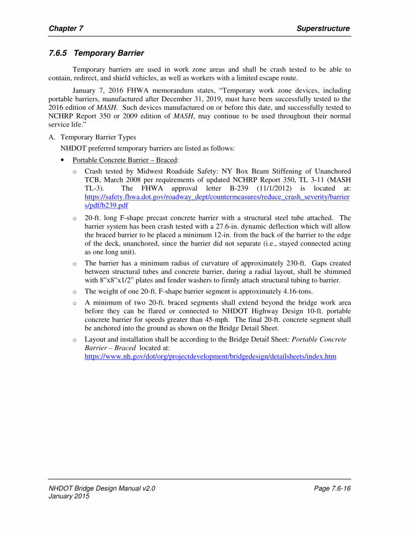
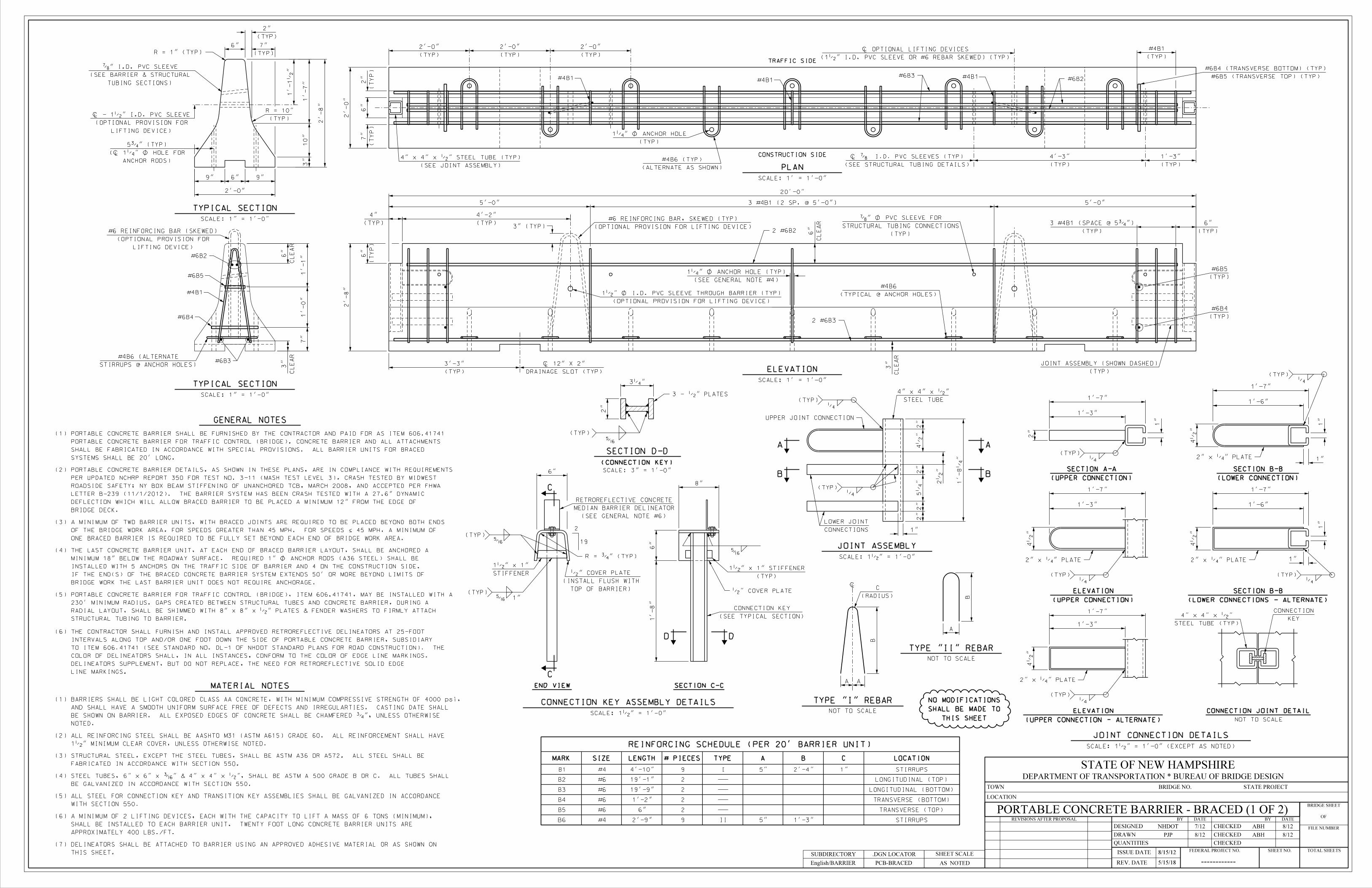
• Portable Concrete Barrier – Braced:
o Crash tested by Midwest Roadside Safety: NY Box Beam Stiffening of Unanchored
TCB, March 2008 per requirements of updated NCHRP Report 350, TL 3-11 (MASH
TL-3). The FHWA approval letter B-239 (11/1/2012) is located at:
https://safety.fhwa.dot.gov/roadway_dept/countermeasures/reduce_crash_severity/barrier
s/pdf/b239.pdf
o 20-ft. long F-shape precast concrete barrier with a structural steel tube attached. The
barrier system has been crash tested with a 27.6-in. dynamic deflection which will allow
the braced barrier to be placed a minimum 12-in. from the back of the barrier to the edge
of the deck, unanchored, since the barrier did not separate (i.e., stayed connected acting
as one long unit).
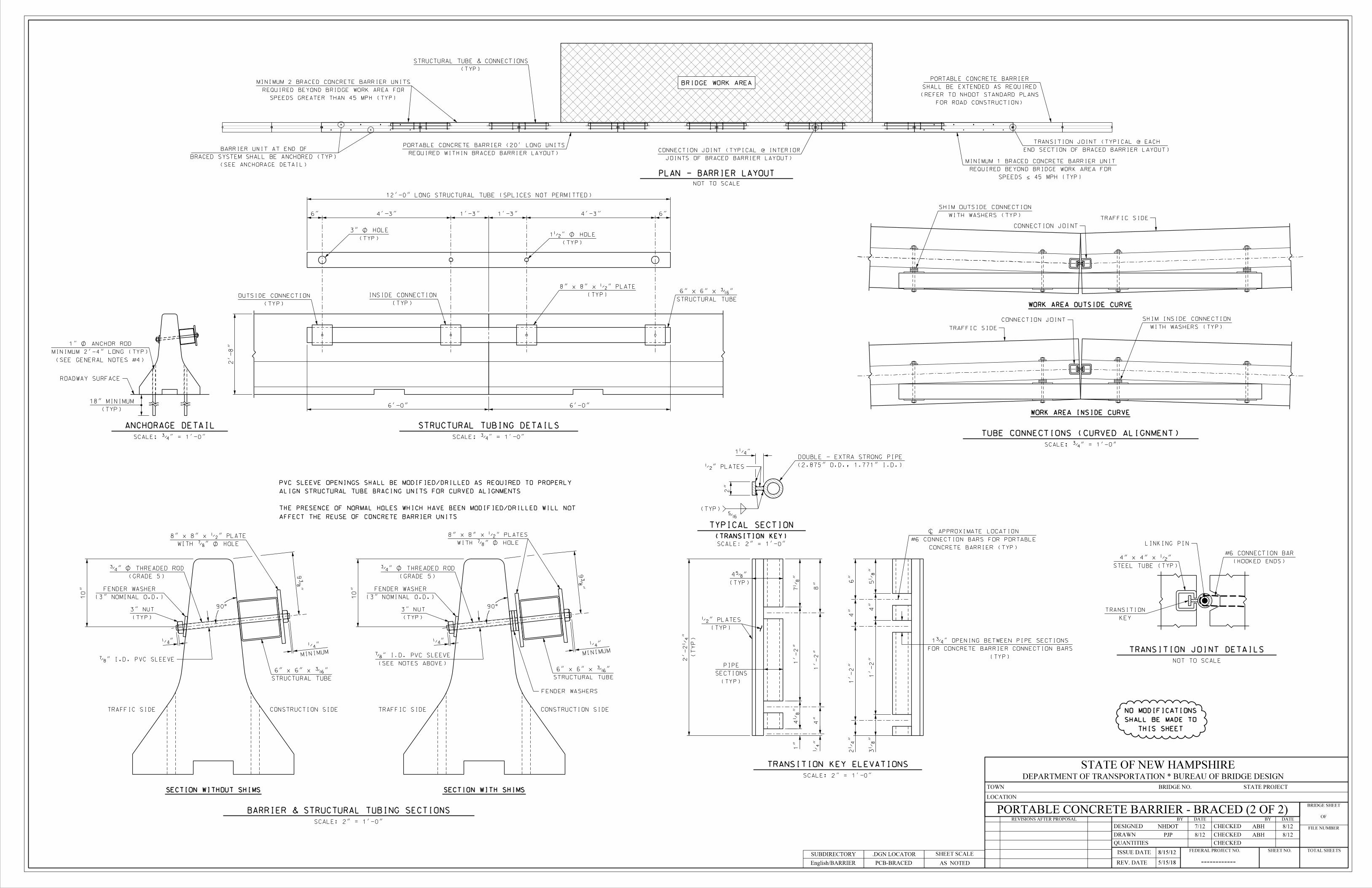
o The barrier has a minimum radius of curvature of approximately 230-ft. Gaps created
between structural tubes and concrete barrier, during a radial layout, shall be shimmed
with 8”x8”x1/2” plates and fender washers to firmly attach structural tubing to barrier.
o The weight of one 20-ft. F-shape barrier segment is approximately 4.16-tons.
o A minimum of two 20-ft. braced segments shall extend beyond the bridge work area
before they can be flared or connected to NHDOT Highway Design 10-ft. portable
concrete barrier for speeds greater than 45-mph. The final 20-ft. concrete segment shall
be anchored into the ground as shown on the Bridge Detail Sheet.
o Layout and installation shall be according to the Bridge Detail Sheet: Portable Concrete
Barrier – Braced located at:
https://www.nh.gov/dot/org/projectdevelopment/bridgedesign/detailsheets/index.htm
Chapter 7 Superstructure
NHDOT Bridge Design Manual v2.0 Page 7.6-17 January 2015
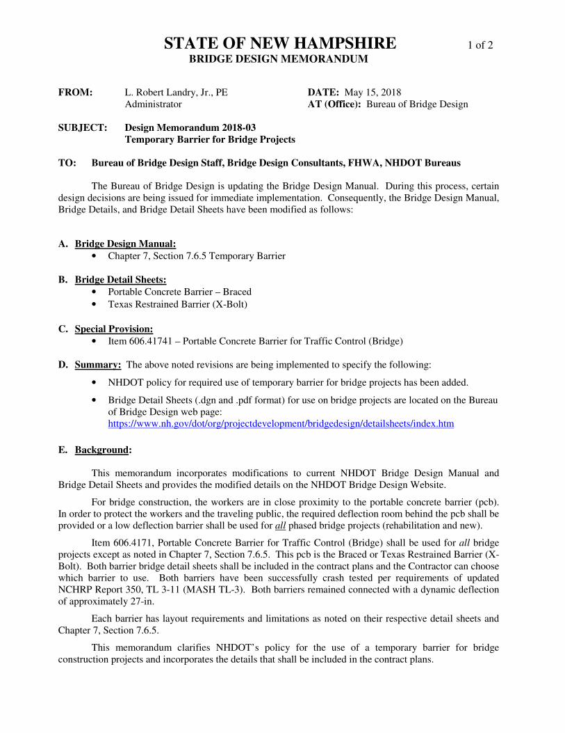
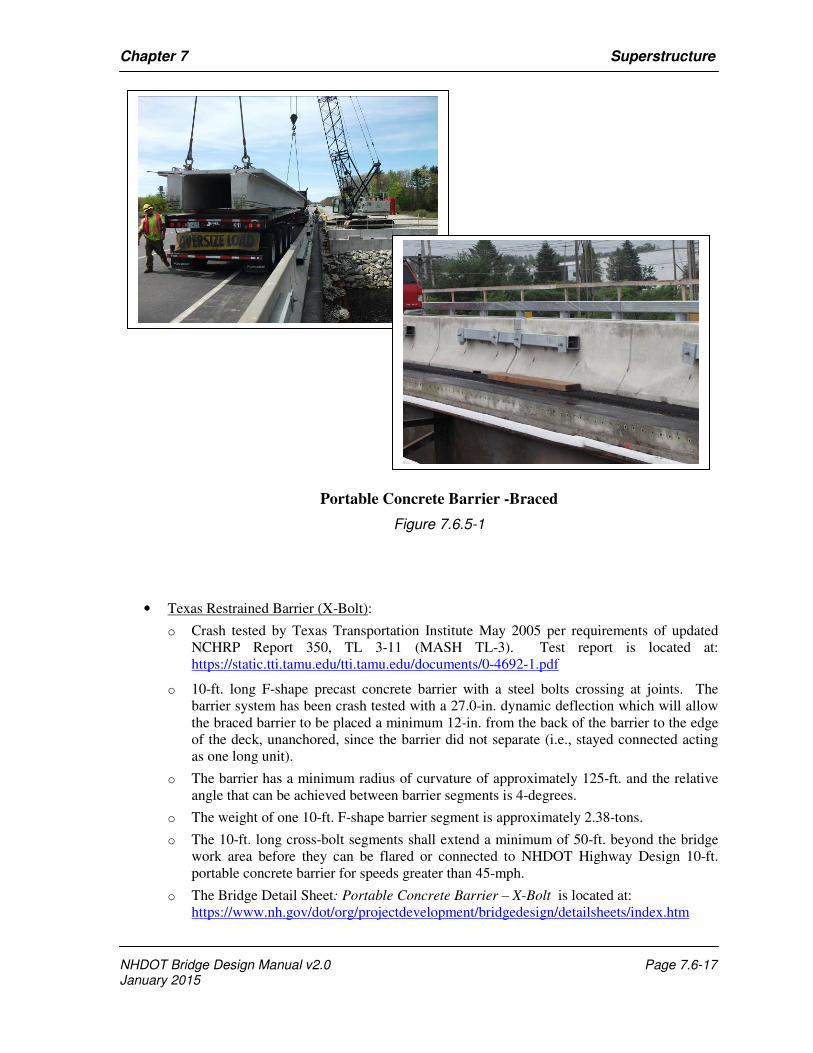
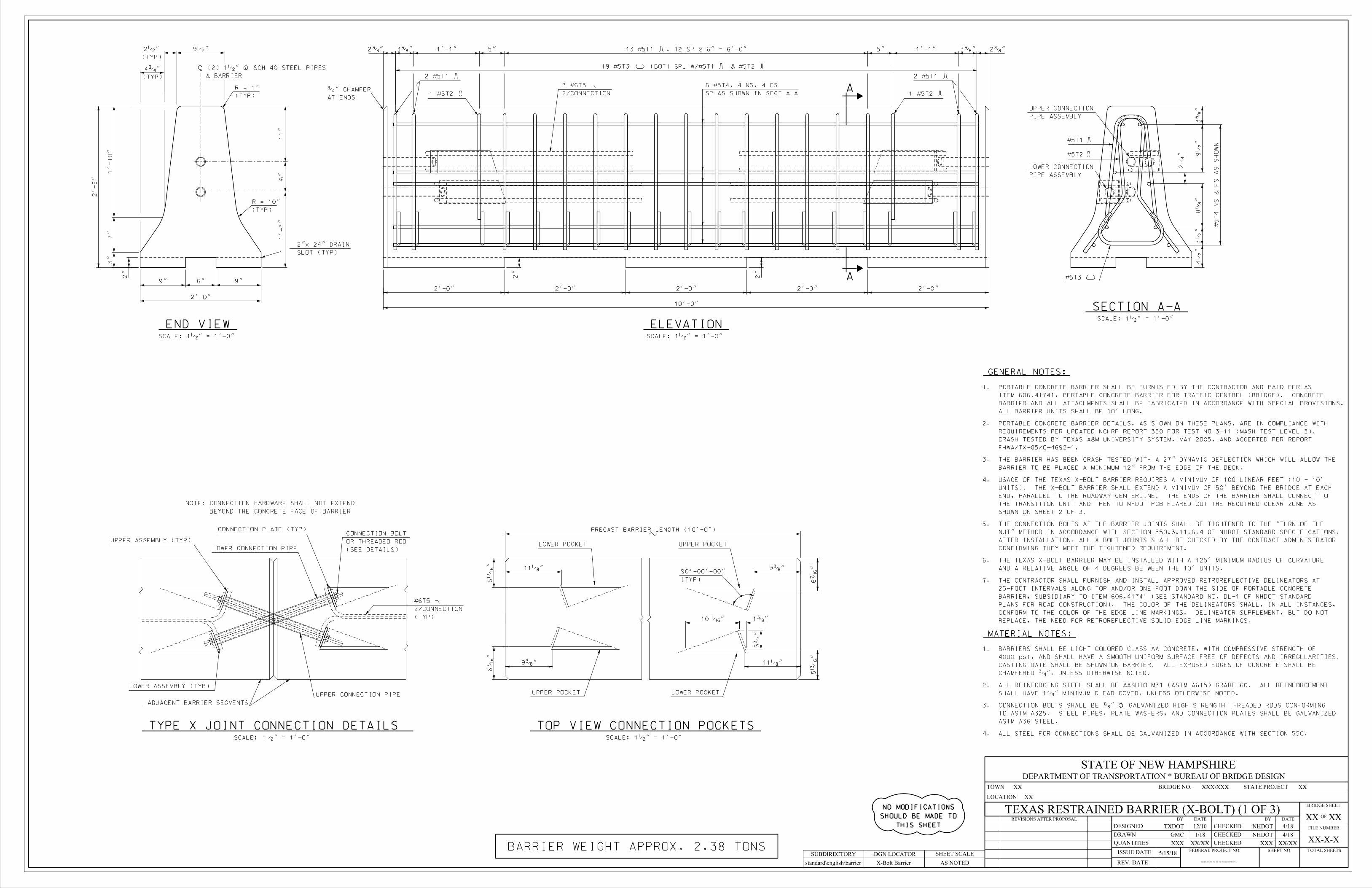
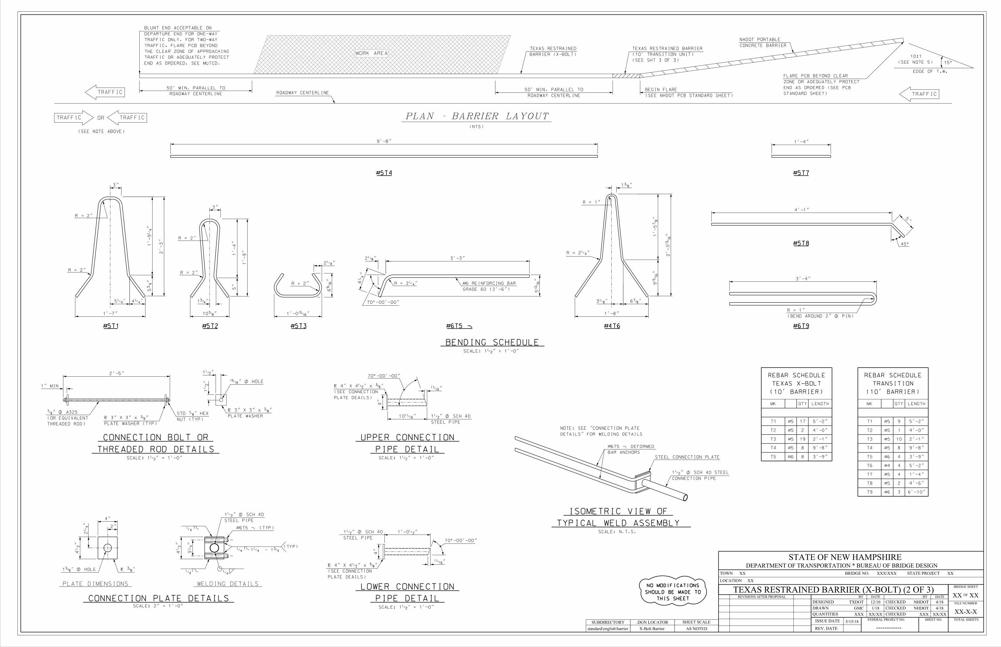
• Texas Restrained Barrier (X-Bolt):
o Crash tested by Texas Transportation Institute May 2005 per requirements of updated
NCHRP Report 350, TL 3-11 (MASH TL-3). Test report is located at:
https://static.tti.tamu.edu/tti.tamu.edu/documents/0-4692-1.pdf
o 10-ft. long F-shape precast concrete barrier with a steel bolts crossing at joints. The
barrier system has been crash tested with a 27.0-in. dynamic deflection which will allow
the braced barrier to be placed a minimum 12-in. from the back of the barrier to the edge
of the deck, unanchored, since the barrier did not separate (i.e., stayed connected acting
as one long unit).
o The barrier has a minimum radius of curvature of approximately 125-ft. and the relative
angle that can be achieved between barrier segments is 4-degrees.
o The weight of one 10-ft. F-shape barrier segment is approximately 2.38-tons.
o The 10-ft. long cross-bolt segments shall extend a minimum of 50-ft. beyond the bridge
work area before they can be flared or connected to NHDOT Highway Design 10-ft.
portable concrete barrier for speeds greater than 45-mph.
o The Bridge Detail Sheet: Portable Concrete Barrier – X-Bolt is located at:
https://www.nh.gov/dot/org/projectdevelopment/bridgedesign/detailsheets/index.htm
Portable Concrete Barrier -Braced
Figure 7.6.5-1
Chapter 7 Superstructure
NHDOT Bridge Design Manual v2.0 Page 7.6-18 January 2015
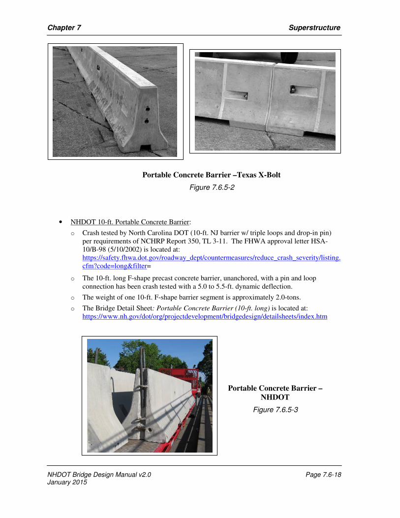
• NHDOT 10-ft. Portable Concrete Barrier:
o Crash tested by North Carolina DOT (10-ft. NJ barrier w/ triple loops and drop-in pin)
per requirements of NCHRP Report 350, TL 3-11. The FHWA approval letter HSA-
10/B-98 (5/10/2002) is located at:
https://safety.fhwa.dot.gov/roadway_dept/countermeasures/reduce_crash_severity/listing.
cfm?code=long&filter=
o The 10-ft. long F-shape precast concrete barrier, unanchored, with a pin and loop
connection has been crash tested with a 5.0 to 5.5-ft. dynamic deflection.
o The weight of one 10-ft. F-shape barrier segment is approximately 2.0-tons.
o The Bridge Detail Sheet: Portable Concrete Barrier (10-ft. long) is located at:
https://www.nh.gov/dot/org/projectdevelopment/bridgedesign/detailsheets/index.htm
Portable Concrete Barrier –Texas X-Bolt
Figure 7.6.5-2
Portable Concrete Barrier –
NHDOT
Figure 7.6.5-3
Chapter 7 Superstructure
NHDOT Bridge Design Manual v2.0 Page 7.6-19 January 2015
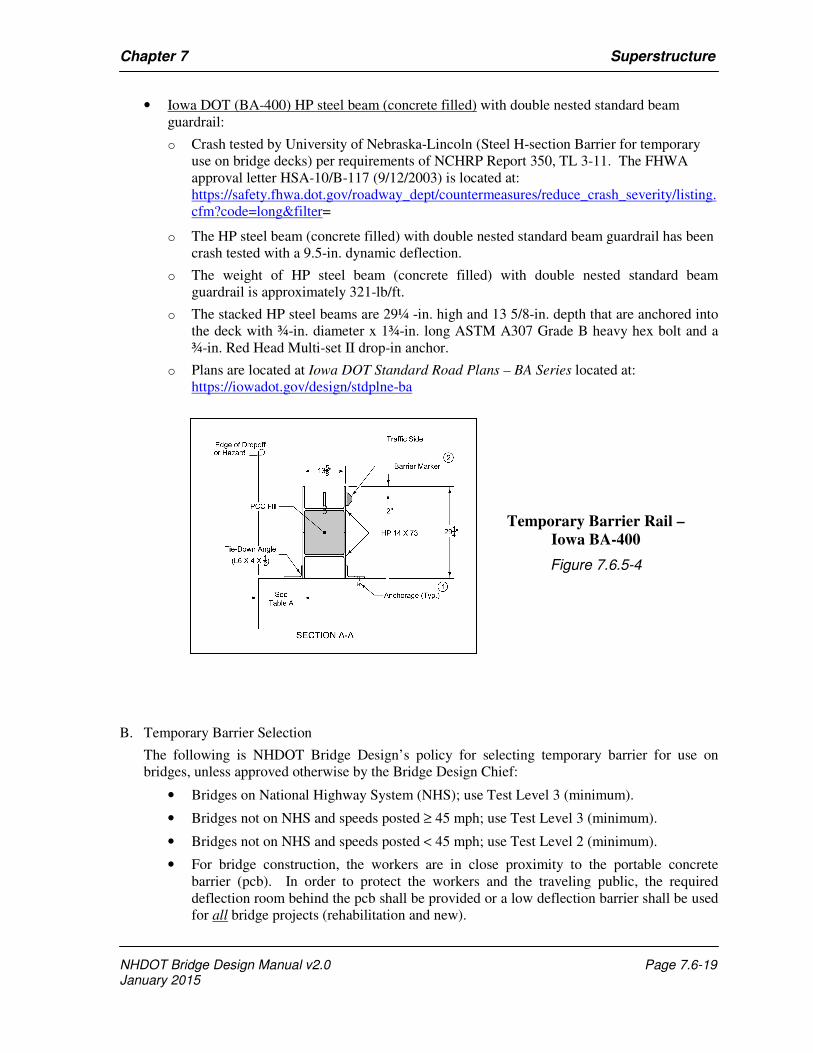
• Iowa DOT (BA-400) HP steel beam (concrete filled) with double nested standard beam
guardrail:
o Crash tested by University of Nebraska-Lincoln (Steel H-section Barrier for temporary
use on bridge decks) per requirements of NCHRP Report 350, TL 3-11. The FHWA
approval letter HSA-10/B-117 (9/12/2003) is located at:
https://safety.fhwa.dot.gov/roadway_dept/countermeasures/reduce_crash_severity/listing.
cfm?code=long&filter=
o The HP steel beam (concrete filled) with double nested standard beam guardrail has been
crash tested with a 9.5-in. dynamic deflection.
o The weight of HP steel beam (concrete filled) with double nested standard beam
guardrail is approximately 321-lb/ft.
o The stacked HP steel beams are 29¼ -in. high and 13 5/8-in. depth that are anchored into
the deck with ¾-in. diameter x 1¾-in. long ASTM A307 Grade B heavy hex bolt and a
¾-in. Red Head Multi-set II drop-in anchor.
o Plans are located at Iowa DOT Standard Road Plans – BA Series located at:
https://iowadot.gov/design/stdplne-ba
B. Temporary Barrier Selection
The following is NHDOT Bridge Design’s policy for selecting temporary barrier for use on
bridges, unless approved otherwise by the Bridge Design Chief:
• Bridges on National Highway System (NHS); use Test Level 3 (minimum).
• Bridges not on NHS and speeds posted ≥ 45 mph; use Test Level 3 (minimum).
• Bridges not on NHS and speeds posted < 45 mph; use Test Level 2 (minimum).
• For bridge construction, the workers are in close proximity to the portable concrete
barrier (pcb). In order to protect the workers and the traveling public, the required
deflection room behind the pcb shall be provided or a low deflection barrier shall be used
for all bridge projects (rehabilitation and new).
Temporary Barrier Rail –
Iowa BA-400
Figure 7.6.5-4
Chapter 7 Superstructure
NHDOT Bridge Design Manual v2.0 Page 7.6-20 January 2015
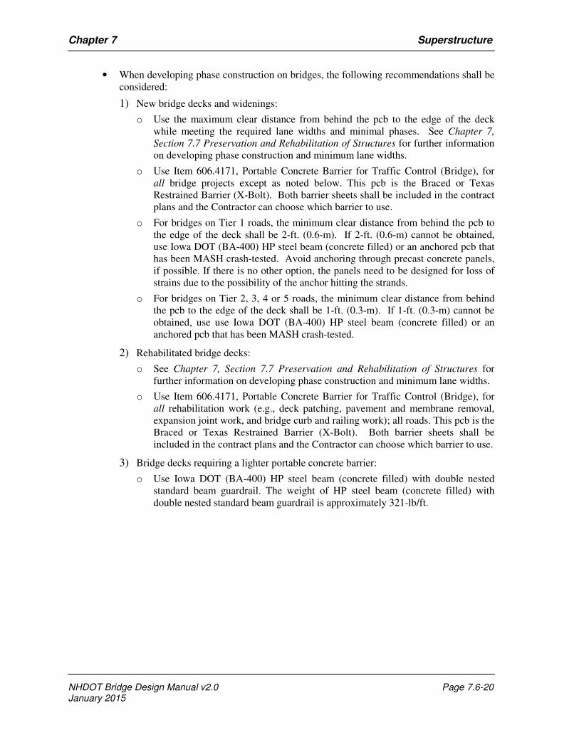
• When developing phase construction on bridges, the following recommendations shall be
considered:
1) New bridge decks and widenings:
o Use the maximum clear distance from behind the pcb to the edge of the deck
while meeting the required lane widths and minimal phases. See Chapter 7,
Section 7.7 Preservation and Rehabilitation of Structures for further information
on developing phase construction and minimum lane widths.
o Use Item 606.4171, Portable Concrete Barrier for Traffic Control (Bridge), for
all bridge projects except as noted below. This pcb is the Braced or Texas
Restrained Barrier (X-Bolt). Both barrier sheets shall be included in the contract
plans and the Contractor can choose which barrier to use.
o For bridges on Tier 1 roads, the minimum clear distance from behind the pcb to
the edge of the deck shall be 2-ft. (0.6-m). If 2-ft. (0.6-m) cannot be obtained,
use Iowa DOT (BA-400) HP steel beam (concrete filled) or an anchored pcb that
has been MASH crash-tested. Avoid anchoring through precast concrete panels,
if possible. If there is no other option, the panels need to be designed for loss of
strains due to the possibility of the anchor hitting the strands.
o For bridges on Tier 2, 3, 4 or 5 roads, the minimum clear distance from behind
the pcb to the edge of the deck shall be 1-ft. (0.3-m). If 1-ft. (0.3-m) cannot be
obtained, use use Iowa DOT (BA-400) HP steel beam (concrete filled) or an
anchored pcb that has been MASH crash-tested.
2) Rehabilitated bridge decks:
o See Chapter 7, Section 7.7 Preservation and Rehabilitation of Structures for
further information on developing phase construction and minimum lane widths.
o Use Item 606.4171, Portable Concrete Barrier for Traffic Control (Bridge), for
all rehabilitation work (e.g., deck patching, pavement and membrane removal,
expansion joint work, and bridge curb and railing work); all roads. This pcb is the
Braced or Texas Restrained Barrier (X-Bolt). Both barrier sheets shall be
included in the contract plans and the Contractor can choose which barrier to use.
3) Bridge decks requiring a lighter portable concrete barrier:
o Use Iowa DOT (BA-400) HP steel beam (concrete filled) with double nested
standard beam guardrail. The weight of HP steel beam (concrete filled) with
double nested standard beam guardrail is approximately 321-lb/ft.
606
04/24/17
SSD: 8/13/2012, 01/10/16 Page 1 of 1
PORTSMOUTH 13455D
PORTSMOUTH 13455E
July 6, 2017
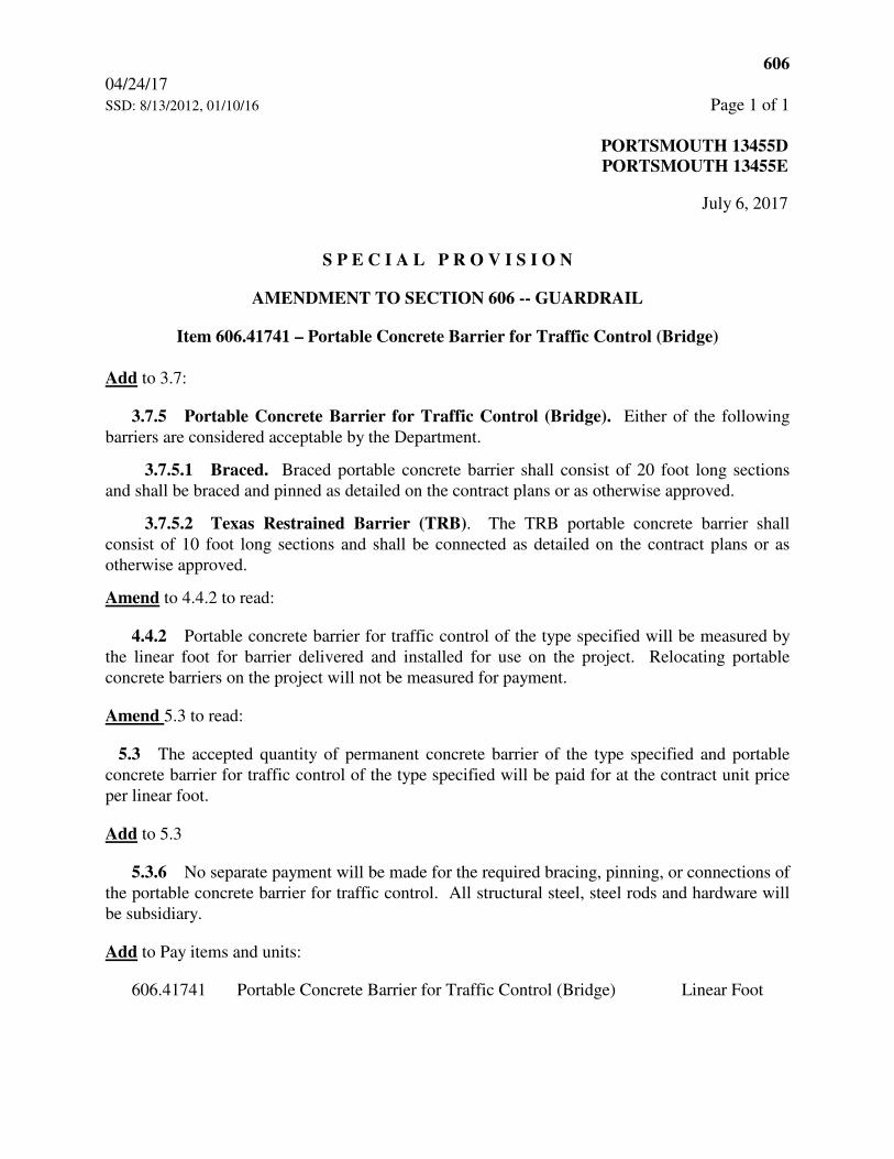
S P E C I A L P R O V I S I O N
AMENDMENT TO SECTION 606 -- GUARDRAIL
Item 606.41741 – Portable Concrete Barrier for Traffic Control (Bridge)
Add to 3.7:
3.7.5 Portable Concrete Barrier for Traffic Control (Bridge). Either of the following
barriers are considered acceptable by the Department.
3.7.5.1 Braced. Braced portable concrete barrier shall consist of 20 foot long sections
and shall be braced and pinned as detailed on the contract plans or as otherwise approved.
3.7.5.2 Texas Restrained Barrier (TRB). The TRB portable concrete barrier shall
consist of 10 foot long sections and shall be connected as detailed on the contract plans or as
otherwise approved.
Amend to 4.4.2 to read:
4.4.2 Portable concrete barrier for traffic control of the type specified will be measured by
the linear foot for barrier delivered and installed for use on the project. Relocating portable
concrete barriers on the project will not be measured for payment.
Amend 5.3 to read:
5.3 The accepted quantity of permanent concrete barrier of the type specified and portable
concrete barrier for traffic control of the type specified will be paid for at the contract unit price
per linear foot.
Add to 5.3
5.3.6 No separate payment will be made for the required bracing, pinning, or connections of
the portable concrete barrier for traffic control. All structural steel, steel rods and hardware will
be subsidiary.
Add to Pay items and units:
606.41741 Portable Concrete Barrier for Traffic Control (Bridge) Linear Foot
2…"3†"1'-1"5"
10'-0"
5"1'-1"3†"2…"
2‚
"
9•
"
8†
"
3•
"
4•
"
3†
"
2'-0"
2'-0"
2'-0"
2'-0"
2'-0"
2"
2"
19 #5T3 (BOT) SPL W/#5T1 & #5T2
#5
T4
NS
&
FS
AS
SH
OW
N
13 #5T1 , 12 SP @ 6" = 6'-0"9•"
2'-
8"
1'-
10"
7"
3"
11"
6"
1'-3"
2"
(TYP)
2•"
(TYP)
4ƒ"
2'-0"
9"6"9"
1…"
11„"
10•"
3ƒ
"
9…"
9…"
11„"
6‹
"5
Ž"
5Ž
"6‹
"
SUBDIRECTORY
X-Bolt Barrier
.DGN LOCATOR
XX
XX XXX\XXX XX
XX XX
XX/XXXXXXX-X-X
------------
XX/XXXXX
AS NOTED
GENERAL NOTES:
BARRIER WEIGHT APPROX. 2.38 TONS
GMC 1/18
MATERIAL NOTES:
CHAMFERED ƒ", UNLESS OTHERWISE NOTED.
CASTING DATE SHALL BE SHOWN ON BARRIER. ALL EXPOSED EDGES OF CONCRETE SHALL BE
4000 psi, AND SHALL HAVE A SMOOTH UNIFORM SURFACE FREE OF DEFECTS AND IRREGULARITIES.
1. BARRIERS SHALL BE LIGHT COLORED CLASS AA CONCRETE, WITH COMPRESSIVE STRENGTH OF
4. ALL STEEL FOR CONNECTIONS SHALL BE GALVANIZED IN ACCORDANCE WITH SECTION 550.
FHWA/TX-05/0-4692-1.
CRASH TESTED BY TEXAS A&M UNIVERSITY SYSTEM, MAY 2005, AND ACCEPTED PER REPORT
REQUIREMENTS PER UPDATED NCHRP REPORT 350 FOR TEST NO 3-11 (MASH TEST LEVEL 3),
2. PORTABLE CONCRETE BARRIER DETAILS, AS SHOWN ON THESE PLANS, ARE IN COMPLIANCE WITH
BARRIER TO BE PLACED A MINIMUM 12" FROM THE EDGE OF THE DECK.
3. THE BARRIER HAS BEEN CRASH TESTED WITH A 27" DYNAMIC DEFLECTION WHICH WILL ALLOW THE
SHOWN ON SHEET 2 OF 3.
THE TRANSITION UNIT AND THEN TO NHDOT PCB FLARED OUT THE REQUIRED CLEAR ZONE AS
END, PARALLEL TO THE ROADWAY CENTERLINE. THE ENDS OF THE BARRIER SHALL CONNECT TO
UNITS). THE X-BOLT BARRIER SHALL EXTEND A MINIMUM OF 50' BEYOND THE BRIDGE AT EACH
4. USAGE OF THE TEXAS X-BOLT BARRIER REQUIRES A MINIMUM OF 100 LINEAR FEET (10 - 10'
CONFIRMING THEY MEET THE TIGHTENED REQUIREMENT.
AFTER INSTALLATION, ALL X-BOLT JOINTS SHALL BE CHECKED BY THE CONTRACT ADMINISTRATOR
NUT" METHOD IN ACCORDANCE WITH SECTION 550.3.11.6.4 OF NHDOT STANDARD SPECIFICATIONS.
5. THE CONNECTION BOLTS AT THE BARRIER JOINTS SHALL BE TIGHTENED TO THE "TURN OF THE
AND A RELATIVE ANGLE OF 4 DEGREES BETWEEN THE 10' UNITS.
6. THE TEXAS X-BOLT BARRIER MAY BE INSTALLED WITH A 125' MINIMUM RADIUS OF CURVATURE
REPLACE, THE NEED FOR RETROREFLECTIVE SOLID EDGE LINE MARKINGS.
CONFORM TO THE COLOR OF THE EDGE LINE MARKINGS. DELINEATOR SUPPLEMENT, BUT DO NOT
PLANS FOR ROAD CONSTRUCTION). THE COLOR OF THE DELINEATORS SHALL, IN ALL INSTANCES,
BARRIER, SUBSIDIARY TO ITEM 606.41741 (SEE STANDARD NO. DL-1 OF NHDOT STANDARD
25-FOOT INTERVALS ALONG TOP AND/OR ONE FOOT DOWN THE SIDE OF PORTABLE CONCRETE
7. THE CONTRACTOR SHALL FURNISH AND INSTALL APPROVED RETROREFLECTIVE DELINEATORS AT
TEXAS RESTRAINED BARRIER (X-BOLT) (1 OF 3)
STATE OF NEW HAMPSHIREDEPARTMENT OF TRANSPORTATION * BUREAU OF BRIDGE DESIGN
BRIDGE NO. STATE PROJECTTOWN
LOCATION
REVISIONS AFTER PROPOSAL
SHEET SCALE
DESIGNED
DRAWN
QUANTITIES
REV. DATE
ISSUE DATE FEDERAL PROJECT NO. SHEET NO. TOTAL SHEETS
FILE NUMBER
OF
BRIDGE SHEET
DATEBY
CHECKED
CHECKED
CHECKED
DATEBY
SHALL HAVE 1ƒ" MINIMUM CLEAR COVER, UNLESS OTHERWISE NOTED.
2. ALL REINFORCING STEEL SHALL BE AASHTO M31 (ASTM A615) GRADE 60. ALL REINFORCEMENT
ALL BARRIER UNITS SHALL BE 10' LONG.
BARRIER AND ALL ATTACHMENTS SHALL BE FABRICATED IN ACCORDANCE WITH SPECIAL PROVISIONS.
ITEM 606.41741, PORTABLE CONCRETE BARRIER FOR TRAFFIC CONTROL (BRIDGE). CONCRETE
1. PORTABLE CONCRETE BARRIER SHALL BE FURNISHED BY THE CONTRACTOR AND PAID FOR AS
ASTM A36 STEEL.
TO ASTM A325. STEEL PIPES, PLATE WASHERS, AND CONNECTION PLATES SHALL BE GALVANIZED
3. CONNECTION BOLTS SHALL BE ‡" Â GALVANIZED HIGH STRENGTH THREADED RODS CONFORMING
TXDOT NHDOT
NHDOT
4/18
4/18
THIS SHEET
SHOULD BE MADE TO
NO MODIFICATIONS
12/10
standard\english\barrier
5/15/18
SCALE: 1•" = 1'-0" SCALE: 1•" = 1'-0"
ELEVATION SCALE: 1•" = 1'-0"
END VIEW
AT ENDS
ƒ" CHAMFER
SECTION A-A
PIPE ASSEMBLY
UPPER CONNECTION
PIPE ASSEMBLY
LOWER CONNECTION
2/CONNECTION
8 #6T5 Ú
#5T1
#5T2
#5T3
2 #5T1
1 #5T2
2 #5T1
1 #5T2 SP AS SHOWN IN SECT A-A
8 #5T4, 4 NS, 4 FSA
A
(TYP)
R = 10"
(TYP)
R = 1"
SLOT (TYP)
2"x 24" DRAIN
& BARRIER
À (2) 1•" Â SCH 40 STEEL PIPES
SCALE: 1•" = 1'-0" SCALE: 1•" = 1'-0"
TOP VIEW CONNECTION POCKETS
LOWER CONNECTION PIPE
CONNECTION PLATE (TYP)
UPPER ASSEMBLY (TYP)
LOWER ASSEMBLY (TYP)
ADJACENT BARRIER SEGMENTS
UPPER CONNECTION PIPE
(SEE DETAILS)
OR THREADED ROD
CONNECTION BOLT
TYPE X JOINT CONNECTION DETAILS
UPPER POCKETLOWER POCKET
UPPER POCKET LOWER POCKET
(TYP)
90°-00'-00"
PRECAST BARRIER LENGTH (10'-0")
BEYOND THE CONCRETE FACE OF BARRIER
NOTE: CONNECTION HARDWARE SHALL NOT EXTEND
(TYP)
2/CONNECTION
#6T5 Ú
1'-0•"
2„"
6Œ
"
2'-
3"
1'-7"
4‚"5‚"
1'-9"
10†"
1'-9‚
"5ƒ
"
1'-4"
5"
1ƒ"
2„"
5Ž
"
3'-3"
6‚
"
3"
3"
2'-
3Ž
"1'-5‡
"9•
"
1'-8"
6‡"3„"
1…"
3'-4"
4'-1"
5"
1'-4"9'-8"
10•"
1'-0•"
•"
•"
4"
4"
3‚
"
4•
"
2‚
"
4"
2"
4•
"
1" MIN
1•"
1•
"
2'-5"
#5
#5
#5
#5
17
2
8
19
5'-2"
4'-0"
9'-8"
2'-1"
MK QTY LENGTH
XX
XX XXX\XXX XX
XX XX
XX/XXXXXXX-X-X
------------
XX/XXXXX
GMC 1/18
SUBDIRECTORY
X-Bolt Barrier
.DGN LOCATOR
AS NOTED
TEXAS RESTRAINED BARRIER (X-BOLT) (2 OF 3)
TRAFFIC
TRAFFIC
OR
WORK AREA
TRAFFIC
TRAFFIC
BARRIER (X-BOLT)
TEXAS RESTRAINED
ROADWAY CENTERLINE
50' MIN. PARALLEL TO
(SEE NOTE 5)
10:1
EDGE OF T.W.
15°
(NTS)
ROADWAY CENTERLINE
50' MIN. PARALLEL TO
(SEE NOTE ABOVE)
ROADWAY CENTERLINE
END AS ORDERED. SEE MUTCD.
TRAFFIC OR ADEQUATELY PROTECT
THE CLEAR ZONE OF APPROACHING
TRAFFIC, FLARE PCB BEYOND
TRAFFIC ONLY. FOR TWO-WAY
DEPARTURE END FOR ONE-WAY
BLUNT END ACCEPTABLE ON
(SEE SHT 3 OF 3)
(10' TRANSITION UNIT)
TEXAS RESTRAINED BARRIER
PLAN - BARRIER LAYOUT
STANDARD SHEET)
END AS ORDERED (SEE PCB
ZONE OR ADEQUATELY PROTECT
FLARE PCB BEYOND CLEAR
(SEE NHDOT PCB STANDARD SHEET)
BEGIN FLARE
CONCRETE BARRIER
NHDOT PORTABLE
STATE OF NEW HAMPSHIREDEPARTMENT OF TRANSPORTATION * BUREAU OF BRIDGE DESIGN
BRIDGE NO. STATE PROJECTTOWN
LOCATION
REVISIONS AFTER PROPOSAL
SHEET SCALE
DESIGNED
DRAWN
QUANTITIES
REV. DATE
ISSUE DATE FEDERAL PROJECT NO. SHEET NO. TOTAL SHEETS
FILE NUMBER
OF
BRIDGE SHEET
DATEBY
CHECKED
CHECKED
CHECKED
DATEBY
T1
T2
T3
T4
T5 #6 8 3'-9"
#5
#5
#5
#5
9
1
8
10
5'-2"
4'-0"
9'-8"
2'-1"
MK QTY LENGTH
T1
T2
T3
T4
T5
#4 4T6
#5 4T7
#6 4 3'-9"
#5 2T8
#6 3T9
5'-2"
4'-6"
6'-10"
1'-4"
THIS SHEET
SHOULD BE MADE TO
NO MODIFICATIONS
(10' BARRIER)
TEXAS X-BOLT
REBAR SCHEDULE
(10' BARRIER)
TRANSITION
REBAR SCHEDULE
TXDOT 12/10 NHDOT 4/18
4/18NHDOT
standard\english\barrier
5/15/18
SCALE: 1•" = 1'-0"
BENDING SCHEDULE
R = 2"
70°-00'-00"
GRADE 60 (3'-6")
#6 REINFORCING BARR = 2‚"
#5T3#5T2#5T1
R = 2"
R = 2"
R = 2"
R = 2"
#4T6
R = 1"
R = 2‚"
#6T9
#5T8 45°
#5T7
#6T5 Ú
#5T4
(BEND AROUND 2" Â PIN)
R = 1"
70°-00'-00"
SCALE: 1•" = 1'-0"
SCALE: 1•" = 1'-0"
PIPE DETAIL
LOWER CONNECTION
70°-00'-00"
STEEL PIPE
1•" Â SCH 40
STEEL PIPE
1•" Â SCH 40
PLATE DEAILS)
(SEE CONNECTION
Á 4" X 4•" x …"
PLATE DEAILS)
(SEE CONNECTION
Á 4" X 4•" x …"
PIPE DETAIL
UPPER CONNECTION
Á …" 1†" Â HOLE
STEEL PIPE
1•" Â SCH 40
WELDING DETAILS PLATE DIMENSIONS
SCALE: 2" = 1'-0"
#6T5 Ú (TYP)
CONNECTION PLATE DETAILS
‚
‚(TYP)
‚ ‚
1‚ - 1ƒ
THREADED ROD)
(OR EQUIVALENT
‡" Â A325
PLATE WASHER (TYP)
Á 3" X 3" x …"NUT (TYP)
STD ‡" HEXPLATE WASHER
Á 3" X 3" x …"
•" Â HOLE
SCALE: 1•" = 1'-0"
THREADED ROD DETAILS
CONNECTION BOLT OR
STEEL CONNECTION PLATE
TYPICAL WELD ASSEMBLY
ISOMETRIC VIEW OF
SCALE: N.T.S.
DETAILS" FOR WELDING DETAILS
NOTE: SEE "CONNECTION PLATE
CONNECTION PIPE
1•" Â SCH 40 STEEL
BAR ANCHORS
#6T5 Ú DEFORMED
5"1'-1"3†"2…"
10'-0"
2'-0"
2'-0"
2'-0"
2'-0"
2'-0"
2"
2"
7 #5T1 , 6 SP @ 6" = 3'-0"
4 #5T7 (BOT) SPL W/#4T6
3
#6
T9
1'-0"
4 #4T6 , 3 SP @ 12" = 3'-0"
1'-0"
2"
2'-
8"
#5
T4
#4T6 & #5T7#5T1 & #5T3 #5T1 & #5T3
5'-0" (TAPERED SECTION)
10 #5T3 (BOT) SPL W/#5T1 & #5T2
9•
"
8†
"
3•
"
4•
"
3†
"
#5
T4
NS
&
FS
AS
SH
OW
N
2‚
"
9•
"
8†
"
3•
"
4•
"
3†
"
2'-
8"
#5
T4
NS
&
FS
AS
SH
OW
N
2‚
"
6"
4"
1'-
2"
8"
9•"
2'-
8"
1'-1
0"
7"
3"
11"
6"
1'-3"
2"
(TYP)
2•"
(TYP)
4ƒ"
2"
6"
1'-
7"
10"
3"
4ƒ"
2"
(TYP)
7"
(TYP)
2"
2'-0"
6"
4"
1'-
2"
8"
9"6"9"
2'-0"
9"6"9"
3"
2'-
0"
4ƒ
"
2"2"
------------
XX
XX XXX\XXX XX
XX XX
XX/XXXXXXX-X-X
XX/XXXXX
GMC 1/18
AS NOTED
SUBDIRECTORY
X-Bolt Barrier
.DGN LOCATOR
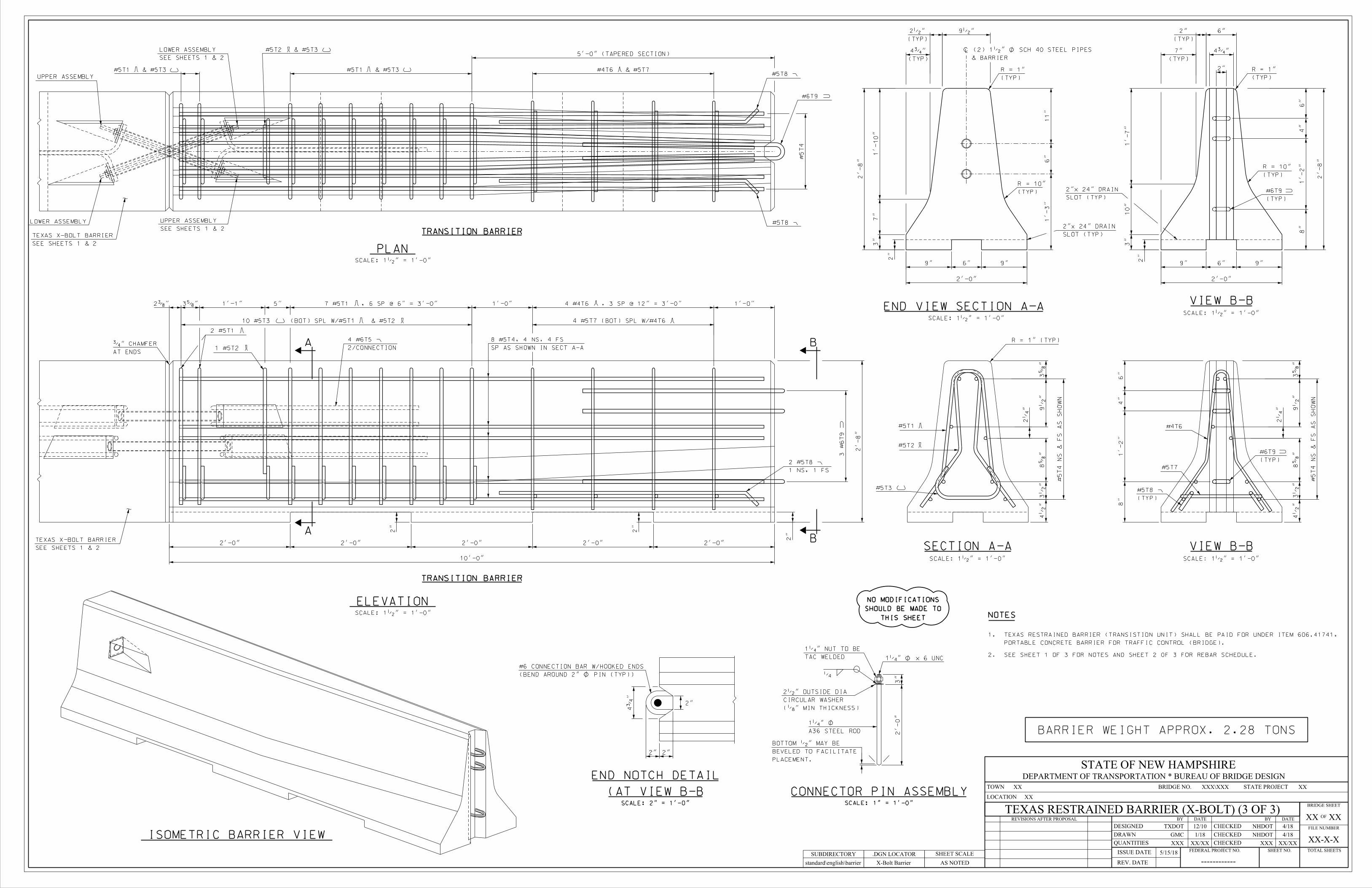
BARRIER WEIGHT APPROX. 2.28 TONS
TEXAS RESTRAINED BARRIER (X-BOLT) (3 OF 3)
STATE OF NEW HAMPSHIREDEPARTMENT OF TRANSPORTATION * BUREAU OF BRIDGE DESIGN
BRIDGE NO. STATE PROJECTTOWN
LOCATION
REVISIONS AFTER PROPOSAL
SHEET SCALE
DESIGNED
DRAWN
QUANTITIES
REV. DATE
ISSUE DATE FEDERAL PROJECT NO. SHEET NO. TOTAL SHEETS
FILE NUMBER
OF
BRIDGE SHEET
DATEBY
CHECKED
CHECKED
CHECKED
DATEBY
THIS SHEET
SHOULD BE MADE TO
NO MODIFICATIONS
NOTES
PORTABLE CONCRETE BARRIER FOR TRAFFIC CONTROL (BRIDGE).
1. TEXAS RESTRAINED BARRIER (TRANSISTION UNIT) SHALL BE PAID FOR UNDER ITEM 606.41741,
2. SEE SHEET 1 OF 3 FOR NOTES AND SHEET 2 0F 3 FOR REBAR SCHEDULE.
TXDOT 12/10 NHDOT
NHDOT
4/18
4/18
standard\english\barrier
5/15/18
SCALE: 1•" = 1'-0"
ELEVATION
SCALE: 1•" = 1'-0"
PLAN
TRANSITION BARRIER
TRANSITION BARRIER
#5T2 & #5T3
#5T8 Ú
A
A
B
B
2/CONNECTION
4 #6T5 Ú
SP AS SHOWN IN SECT A-A
8 #5T4, 4 NS, 4 FS
AT ENDS
ƒ" CHAMFER
2 #5T1
1 #5T2
UPPER ASSEMBLY
LOWER ASSEMBLY
1 NS, 1 FS
2 #5T8 Ú
#5T8 Ú
#6T9
SEE SHEETS 1 & 2
LOWER ASSEMBLY
SEE SHEETS 1 & 2
UPPER ASSEMBLY
SEE SHEETS 1 & 2
TEXAS X-BOLT BARRIER
SEE SHEETS 1 & 2
TEXAS X-BOLT BARRIER
SCALE: 1•" = 1'-0" SCALE: 1•" = 1'-0"
#5T3
#5T1
#5T2
SECTION A-A
(TYP)
#5T8 Ú
#5T7
#4T6
(TYP)
#6T9
R = 1" (TYP)
VIEW B-B
SCALE: 1•" = 1'-0"
(TYP)
R = 10"
(TYP)
R = 1"
SLOT (TYP)
2"x 24" DRAIN
END VIEW SECTION A-ASCALE: 1•" = 1'-0"
VIEW B-B
(TYP)
R = 10"
(TYP)
R = 1"
SLOT (TYP)
2"x 24" DRAIN
(TYP)
#6T9
& BARRIER
À (2) 1•" Â SCH 40 STEEL PIPES
SCALE: 1" = 1'-0"
PLACEMENT.
BEVELED TO FACILITATE
BOTTOM •" MAY BE
CONNECTOR PIN ASSEMBLY
(„" MIN THICKNESS)
CIRCULAR WASHER
2•" OUTSIDE DIA
‚
A36 STEEL ROD
1‚" Â
TAC WELDED
1‚" NUT TO BE
1‚" Â x 6 UNC
SCALE: 2" = 1'-0"
(BEND AROUND 2" Â PIN (TYP))
#6 CONNECTION BAR W/HOOKED ENDS
2"
(AT VIEW B-B
END NOTCH DETAIL
ISOMETRIC BARRIER VIEW
B
AA
B
A
20'-0"
(TYP)
3'-3"
2'-
8"
(TYP)
2'-0"
(TYP)
2'-0"
(TYP)
2'-0"
6"
(T
YP)
7"
(T
YP)
2"
(T
YP)
6"
(TYP)
3 #4B1 (SPACE @ 5ƒ")
(TYP)
#4B1
(TYP)
4'-2"
(TYP)
1'-3"
(TYP)
4'-3"
CL
EA
R
6"
5'-0"3 #4B1 (2 SP. @ 5'-0")5'-0"
(TYP)
4"
9"6"9"
2'-0"
6"
1'-
1"
1'-
0"
7"
1'-
7"
10"
3"
1'-
1•
"
(TYP)
7"
(TYP)
2"
2'-
8"
2'-
0"
CL
EA
R
3"
CL
EA
R
3"
CL
EA
R
6"
4•
"4•
"
4•
"4•
"
1'-7"
1'-3"
2"
1"
1'-7"
1'-3"
1'-6"
1'-7"
1"
1"
1'-3"
1'-7"
1"
1"
1'-6"
1'-7"
2"
4•
"2"
5‚
"2"
2"
2•
"
1'-8‚
"
1"
6"
6"
1'-
8"
8"
3‚"
2"
STATE OF NEW HAMPSHIREDEPARTMENT OF TRANSPORTATION * BUREAU OF BRIDGE DESIGN
BRIDGE NO.TOWN
LOCATION
STATE PROJECT
BRIDGE SHEET
OF
FILE NUMBER
TOTAL SHEETSSHEET NO.FEDERAL PROJECT NO.
DESIGNED
DRAWN
QUANTITIES CHECKED
CHECKED
CHECKED
BY DATEDATE BYREVISIONS AFTER PROPOSAL
REV. DATE
ISSUE DATESHEET SCALE
AS NOTED
SUBDIRECTORY
English/BARRIER PCB-BRACED
.DGN LOCATOR
PORTABLE CONCRETE BARRIER - BRACED (1 OF 2)
ABH
ABH
------------
PJP
NHDOT 7/12
8/12 8/12
8/12
GENERAL NOTES
MATERIAL NOTES
1•" MINIMUM CLEAR COVER, UNLESS OTHERWISE NOTED.
(2) ALL REINFORCING STEEL SHALL BE AASHTO M31 (ASTM A615) GRADE 60. ALL REINFORCEMENT SHALL HAVE
NOTED.
BE SHOWN ON BARRIER. ALL EXPOSED EDGES OF CONCRETE SHALL BE CHAMFERED ƒ", UNLESS OTHERWISE
AND SHALL HAVE A SMOOTH UNIFORM SURFACE FREE OF DEFECTS AND IRREGULARTIES. CASTING DATE SHALL
(1) BARRIERS SHALL BE LIGHT COLORED CLASS AA CONCRETE, WITH MINIMUM COMPRESSIVE STRENGTH OF 4000 psi,
ONE BRACED BARRIER IS REQUIRED TO BE FULLY SET BEYOND EACH END OF BRIDGE WORK AREA.
OF THE BRIDGE WORK AREA, FOR SPEEDS GREATER THAN 45 MPH. FOR SPEEDS \ 45 MPH, A MINIMUM OF
(3) A MINIMUM OF TWO BARRIER UNITS, WITH BRACED JOINTS ARE REQUIRED TO BE PLACED BEYOND BOTH ENDS
LOCATIONCBATYPESIZEMARK # PIECESLENGTH
1"
REINFORCING SCHEDULE (PER 20' BARRIER UNIT)
5"I9#4B1
B2
B3
B4
B5
#6
#6
#6
#6 26"
2
2
2
4'-10"
19'-1"
19'-9"
1'-2"
LONGITUDINAL (BOTTOM)
STIRRUPS
LONGITUDINAL (TOP)
TRANSVERSE (BOTTOM)
TRANSVERSE (TOP)
2'-4"
NOT TO SCALE
THIS SHEET.
(7) DELINEATORS SHALL BE ATTACHED TO BARRIER USING AN APPROVED ADHESIVE MATERIAL OR AS SHOWN ON
NOT TO SCALE
TYPE "I" REBAR
(RADIUS)
CÀ
TYPE "II" REBAR
5"II9#4B6 2'-9" STIRRUPS1'-3"
8/15/12
5/15/18
FABRICATED IN ACCORDANCE WITH SECTION 550.
(3) STRUCTURAL STEEL, EXCEPT THE STEEL TUBES, SHALL BE ASTM A36 OR A572. ALL STEEL SHALL BE
LINE MARKINGS.
DELINEATORS SUPPLEMENT, BUT DO NOT REPLACE, THE NEED FOR RETROREFLECTIVE SOLID EDGE
COLOR OF DELINEATORS SHALL, IN ALL INSTANCES, CONFORM TO THE COLOR OF EDGE LINE MARKINGS.
TO ITEM 606.41741 (SEE STANDARD NO. DL-1 OF NHDOT STANDARD PLANS FOR ROAD CONSTRUCTION). THE
INTERVALS ALONG TOP AND/OR ONE FOOT DOWN THE SIDE OF PORTABLE CONCRETE BARRIER, SUBSIDIARY
(6) THE CONTRACTOR SHALL FURNISH AND INSTALL APPROVED RETROREFLECTIVE DELINEATORS AT 25-FOOT
BRIDGE WORK THE LAST BARRIER UNIT DOES NOT REQUIRE ANCHORAGE.
IF THE END(S) OF THE BRACED CONCRETE BARRIER SYSTEM EXTENDS 50' OR MORE BEYOND LIMITS OF
INSTALLED WITH 5 ANCHORS ON THE TRAFFIC SIDE OF BARRIER AND 4 ON THE CONSTRUCTION SIDE.
MINIMUM 18" BELOW THE ROADWAY SURFACE. REQUIRED 1" Â ANCHOR RODS (A36 STEEL) SHALL BE
(4) THE LAST CONCRETE BARRIER UNIT, AT EACH END OF BRACED BARRIER LAYOUT, SHALL BE ANCHORED A
SYSTEMS SHALL BE 20' LONG.
SHALL BE FABRICATED IN ACCORDANCE WITH SPECIAL PROVISIONS. ALL BARRIER UNITS FOR BRACED
PORTABLE CONCRETE BARRIER FOR TRAFFIC CONTROL (BRIDGE). CONCRETE BARRIER AND ALL ATTACHMENTS
(1) PORTABLE CONCRETE BARRIER SHALL BE FURNISHED BY THE CONTRACTOR AND PAID FOR AS ITEM 606.41741
BRIDGE DECK.
DEFLECTION WHICH WILL ALLOW BRACED BARRIER TO BE PLACED A MINIMUM 12" FROM THE EDGE OF
LETTER B-239 (11/1/2012). THE BARRIER SYSTEM HAS BEEN CRASH TESTED WITH A 27.6" DYNAMIC
ROADSIDE SAFETY; NY BOX BEAM STIFFENING OF UNANCHORED TCB, MARCH 2008, AND ACCEPTED PER FHWA
PER UPDATED NCHRP REPORT 350 FOR TEST NO. 3-11 (MASH TEST LEVEL 3), CRASH TESTED BY MIDWEST
(2) PORTABLE CONCRETE BARRIER DETAILS, AS SHOWN IN THESE PLANS, ARE IN COMPLIANCE WITH REQUIREMENTS
WITH SECTION 550.
(5) ALL STEEL FOR CONNECTION KEY AND TRANSITION KEY ASSEMBLIES SHALL BE GALVANIZED IN ACCORDANCE
BE GALVANIZED IN ACCORDANCE WITH SECTION 550.
(4) STEEL TUBES, 6" x 6" x ‰" & 4" x 4" x •", SHALL BE ASTM A 500 GRADE B OR C. ALL TUBES SHALL
APPROXIMATELY 400 LBS./FT.
SHALL BE INSTALLED TO EACH BARRIER UNIT. TWENTY FOOT LONG CONCRETE BARRIER UNITS ARE
(6) A MINIMUM OF 2 LIFTING DEVICES, EACH WITH THE CAPACITY TO LIFT A MASS OF 6 TONS (MINIMUM),
STRUCTURAL TUBING TO BARRIER.
RADIAL LAYOUT, SHALL BE SHIMMED WITH 8" x 8" x •" PLATES & FENDER WASHERS TO FIRMLY ATTACH
230' MINIMUM RADIUS. GAPS CREATED BETWEEN STRUCTURAL TUBES AND CONCRETE BARRIER, DURING A
(5) PORTABLE CONCRETE BARRIER FOR TRAFFIC CONTROL (BRIDGE), ITEM 606.41741, MAY BE INSTALLED WITH A
THIS SHEET
SHALL BE MADE TO
NO MODIFICATIONS
SCALE: 1' = 1'-0"
ELEVATION
SCALE: 1' = 1'-0"
PLAN
(TYP)
1‚" Â ANCHOR HOLE
SCALE: 1" = 1'-0"
TYPICAL SECTION
#4B1
2 #6B2
2 #6B3
(TYP)
#6B5
#6B3
#6B2
#6B4
#6B5
#6B2#6B3
(OPTIONAL PROVISION FOR LIFTING DEVICE)
1•" Â I.D. PVC SLEEVE THROUGH BARRIER (TYP)
(OPTIONAL PROVISION FOR LIFTING DEVICE)
#6 REINFORCING BAR, SKEWED (TYP)
DRAINAGE SLOT (TYP)
À 12" X 2"
3" (TYP)
(1•" I.D. PVC SLEEVE OR #6 REBAR SKEWED) (TYP)
À OPTIONAL LIFTING DEVICES
(SEE GENERAL NOTE #4)
1‚" Â ANCHOR HOLE (TYP)
(TYP)
#6B4
TRAFFIC SIDE
CONSTRUCTION SIDE
(TYPICAL @ ANCHOR HOLES)
#4B6
(TYP)
STRUCTURAL TUBING CONNECTIONS
‡" Â PVC SLEEVE FOR
#6B5 (TRANSVERSE TOP) (TYP)
#6B4 (TRANSVERSE BOTTOM) (TYP)
(SEE STRUCTURAL TUBING DETAILS)
À ‡ I.D. PVC SLEEVES (TYP)
(ALTERNATE AS SHOWN)
#4B6 (TYP)
(SEE JOINT ASSEMBLY)
4" x 4" x •" STEEL TUBE (TYP)
(TYP)
JOINT ASSEMBLY (SHOWN DASHED)
#4B1#4B1#4B1
ANCHOR RODS)
(À 1‚" Â HOLE FOR
5ƒ" (TYP)
SCALE: 1" = 1'-0"
TYPICAL SECTION
(TYP)
R = 10"
R = 1" (TYP)
STIRRUPS @ ANCHOR HOLES)
#4B6 (ALTERNATE
LIFTING DEVICE)
(OPTIONAL PROVISION FOR
#6 REINFORCING BAR (SKEWED)
LIFTING DEVICE)
(OPTIONAL PROVISION FOR
À - 1•" I.D. PVC SLEEVE
TUBING SECTIONS)
(SEE BARRIER & STRUCTURAL
‡" I.D. PVC SLEEVE
(TYP)
6"
(TYP)‚
2" x ‚" PLATE
(TYP)‚
2" x ‚" PLATE
(TYP)‚
(TYP)‚
2" x ‚" PLATE
2" x ‚" PLATE
(TYP)‚
JOINT CONNECTION DETAILS
(LOWER CONNECTIONS - ALTERNATE)
SECTION B-B
(UPPER CONNECTION)
SECTION A-A
(LOWER CONNECTION)
SECTION B-B
(UPPER CONNECTION)
ELEVATION
(UPPER CONNECTION - ALTERNATE)
ELEVATION
SCALE: 1•" = 1'-0" (EXCEPT AS NOTED)
NOT TO SCALE
STEEL TUBE (TYP)
4" x 4" x •"KEY
CONNECTION
CONNECTION JOINT DETAIL
SCALE: 1•" = 1'-0"
JOINT ASSEMBLY
(TYP)‚
UPPER JOINT CONNECTION
STEEL TUBE
4" x 4" x •"
CONNECTIONS
LOWER JOINT
(TYP)‚
BB
AA
END VIEW
(TYP)Š
(TYP)Š 1"
R = ƒ" (TYP)
2
19
DD
C
C
Š
(TYP)
1•" x 1" STIFFENER
•" COVER PLATE
SECTION C-C
CONNECTION KEY ASSEMBLY DETAILS
SCALE: 1•" = 1'-0"
STIFFENER
1•" x 1"
TOP OF BARRIER)
(INSTALL FLUSH WITH
•" COVER PLATE
(SEE GENERAL NOTE #6)
MEDIAN BARRIER DELINEATOR
RETROREFLECTIVE CONCRETE
(SEE TYPICAL SECTION)
CONNECTION KEY
Š
(TYP)
3 - •" PLATES
SCALE: 3" = 1'-0"
(CONNECTION KEY)
SECTION D-D
6'-0"6'-0"
6"4'-3"1'-3"1'-3"4'-3"6"
12'-0" LONG STRUCTURAL TUBE (SPLICES NOT PERMITTED)
2'-8"
9…
"
‚ "
MINIMUM
‚ "‚ "
MINIMUM
‚ "
9…
"
10"
10"
2"
1‚"
6"
4"
1'-
2"
5„
"4"
1'-
2"
3„
"
2‚
"
(T
YP)
2'-
2‚
"
(TYP)
4†"
8"
1'-
2"
4"
7„
"1'-
2"
4„
"
‚"
1"
STATE OF NEW HAMPSHIREDEPARTMENT OF TRANSPORTATION * BUREAU OF BRIDGE DESIGN
BRIDGE NO.TOWN
LOCATION
STATE PROJECT
BRIDGE SHEET
OF
FILE NUMBER
TOTAL SHEETSSHEET NO.FEDERAL PROJECT NO.
DESIGNED
DRAWN
QUANTITIES CHECKED
CHECKED
CHECKED
BY DATEDATE BYREVISIONS AFTER PROPOSAL
REV. DATE
ISSUE DATESHEET SCALE
AS NOTED
SUBDIRECTORY
English/BARRIER PCB-BRACED
.DGN LOCATOR
PORTABLE CONCRETE BARRIER - BRACED (2 OF 2)
ABH
ABH
------------
PJP
NHDOT 7/12
8/12 8/12
8/12
8/15/12
5/15/18
THIS SHEET
SHALL BE MADE TO
NO MODIFICATIONS
NOT TO SCALE
PLAN - BARRIER LAYOUT
BRIDGE WORK AREA
FOR ROAD CONSTRUCTION)
(REFER TO NHDOT STANDARD PLANS
SHALL BE EXTENDED AS REQUIRED
PORTABLE CONCRETE BARRIER
(TYP)
STRUCTURAL TUBE & CONNECTIONS
SPEEDS GREATER THAN 45 MPH (TYP)
REQUIRED BEYOND BRIDGE WORK AREA FOR
MINIMUM 2 BRACED CONCRETE BARRIER UNITS
SPEEDS \ 45 MPH (TYP)
REQUIRED BEYOND BRIDGE WORK AREA FOR
MINIMUM 1 BRACED CONCRETE BARRIER UNIT(SEE ANCHORAGE DETAIL)
BRACED SYSTEM SHALL BE ANCHORED (TYP)
BARRIER UNIT AT END OFREQUIRED WITHIN BRACED BARRIER LAYOUT)
PORTABLE CONCRETE BARRIER (20' LONG UNITS
JOINTS OF BRACED BARRIER LAYOUT)
CONNECTION JOINT (TYPICAL @ INTERIOR END SECTION OF BRACED BARRIER LAYOUT)
TRANSITION JOINT (TYPICAL @ EACH
SCALE: ƒ" = 1'-0"
STRUCTURAL TUBING DETAILS
(TYP)
8" x 8" x •" PLATE
(TYP)
OUTSIDE CONNECTION
(TYP)
INSIDE CONNECTION
(TYP)
1•" Â HOLE(TYP)
3" Â HOLE
SCALE: ƒ" = 1'-0"
ANCHORAGE DETAIL
ROADWAY SURFACE
(SEE GENERAL NOTES #4)
MINIMUM 2'-4" LONG (TYP)
1" Â ANCHOR ROD
(TYP)
18" MINIMUM
STRUCTURAL TUBE
6" x 6" x ‰"
SCALE: 2" = 1'-0"
BARRIER & STRUCTURAL TUBING SECTIONS
SECTION WITHOUT SHIMS SECTION WITH SHIMS
(TYP)
3" NUT
TRAFFIC SIDE CONSTRUCTION SIDE
WITH ‡" Â HOLE
8" x 8" x •" PLATE
90°
TRAFFIC SIDE CONSTRUCTION SIDE
90°
WITH ‡" Â HOLE
8" x 8" x •" PLATES
FENDER WASHERS
‡" I.D. PVC SLEEVE(SEE NOTES ABOVE)
‡" I.D. PVC SLEEVE
AFFECT THE REUSE OF CONCRETE BARRIER UNITS
THE PRESENCE OF NORMAL HOLES WHICH HAVE BEEN MODIFIED/DRILLED WILL NOT
ALIGN STRUCTURAL TUBE BRACING UNITS FOR CURVED ALIGNMENTS
PVC SLEEVE OPENINGS SHALL BE MODIFIED/DRILLED AS REQUIRED TO PROPERLY
(GRADE 5)
ƒ" Â THREADED ROD
(3" NOMINAL O.D.)
FENDER WASHER
(TYP)
3" NUT
(GRADE 5)
ƒ" Â THREADED ROD
(3" NOMINAL O.D.)
FENDER WASHER
STRUCTURAL TUBE
6" x 6" x ‰"
STRUCTURAL TUBE
6" x 6" x ‰"
SCALE: ƒ" = 1'-0"
TRAFFIC SIDEWITH WASHERS (TYP)
SHIM OUTSIDE CONNECTION
TRAFFIC SIDE WITH WASHERS (TYP)
SHIM INSIDE CONNECTION
TUBE CONNECTIONS (CURVED ALIGNMENT)
WORK AREA OUTSIDE CURVE
WORK AREA INSIDE CURVE
CONNECTION JOINT
CONNECTION JOINT
Š
(TYP)
•" PLATES
SCALE: 2" = 1'-0"
TYPICAL SECTION
(TRANSITION KEY)
(2.875" O.D., 1.771" I.D.)
DOUBLE - EXTRA STRONG PIPE
SCALE: 2" = 1'-0"
TRANSITION KEY ELEVATIONS
CONCRETE BARRIER (TYP)
#6 CONNECTION BARS FOR PORTABLE
À APPROXIMATE LOCATION
(TYP)
FOR CONCRETE BARRIER CONNECTION BARS
1ƒ" OPENING BETWEEN PIPE SECTIONS
(TYP)
•" PLATES
(TYP)
SECTIONS
PIPE
TRANSITION JOINT DETAILS
STEEL TUBE (TYP)
4" x 4" x •"
KEY
TRANSITION
(HOOKED ENDS)
#6 CONNECTION BAR
LINKING PIN
NOT TO SCALE