Embed Size (px)
Citation preview
LRFD Bridge Manual - Part I, January 2020 Revision 1 - 1
CHAPTER 1 BRIDGE SITE EXPLORATION
1.1 SURVEY FOR BRIDGES 1.1.1 General The following are the minimum survey requirements for bridge projects and the reasons for them. Additional survey beyond these requirements may be needed depending on the complexity of either the proposed bridge structure or the site. The MassDOT Survey Manual shall be used for any additional information on survey theory and methods as practiced by the MassDOT. 1.1.2 Bridge Grid Survey The bridge grid is taken in order that the proposed bridge may be fitted to the topography and an accurate calculation can be made of excavation quantities. It shall be plotted to either ⅛” = 1’- 0” or ¼” = 1’- 0”. The frequency of shots and extent must be a matter of judgment of the survey party. In general, shots should be taken on a 10-foot grid with additional shots as necessary for abrupt changes in contour. They should extend at least 50 feet beyond the edges of the highway or 25 feet beyond the anticipated end of splayed wingwalls, whichever is furthest, and should cover enough ground for any type of structure. The grid should be extended to reflect topography under existing structures. 1.1.3 Bridge Detail Survey The following survey information shall be requested when: a new superstructure is to be built on existing substructures; an existing bridge is to be replaced in stages; an existing bridge is to be widened, repaired, or rehabilitated; or when the underclearances for the existing bridge are important to the underclearances to be provided at the replacement, such as for replacement bridges over water or railroads. The accuracy of surveys on bridge locations shall be greater than on general highway work. A copy of all field notes shall be provided to the Designer.
1. The angles of the abutments with the baseline, the location of tops and bottoms of batters, the widths of bridge seats and backwalls, the location of the angles of the wingwalls with abutments, the length of wingwalls and widths of copings shall be measured and the footings located if possible. The type of masonry in the substructure and its condition should be noted.
2. Detail shall be provided for all main superstructure elements, including beam lines, girder lines,
truss lines, floorbeam lines, curb lines, sidewalks, fascia lines, utilities, copings, ends of bridge, etc. The stations of the centerlines of bearings and the skew angle between them and the survey baseline shall be established or verified at each abutment and at piers.
3. Bottom of beam elevations shall be taken on every beam at: the face of each abutment, both
sides of each pier and span quarter points for spans less than 50 feet, span eighth points for spans over 50 feet. These elevations are needed for calculating the depth of haunches and top of form elevations.
4. Elevations shall be taken of all parts of the substructure and superstructure, such as the bridge
seats, tops and ends of wingwalls, gutters, top of curb at intermediate points and at the ends of
LRFD Bridge Manual - Part I, January 2020 Revision 1 - 2
curbs, tops of slab and footings, if possible. All elevations shall be referred to the North American Vertical Datum (NAVD) of 1988. If only the National Geodetic Vertical Datum (NGVD) of 1929 is available at the site, the Designer shall contact the MassDOT Survey Engineer and obtain the relationship between NAVD and NGVD at the site.
5. Locate and establish the minimum horizontal and vertical underclearances of the existing
structure.
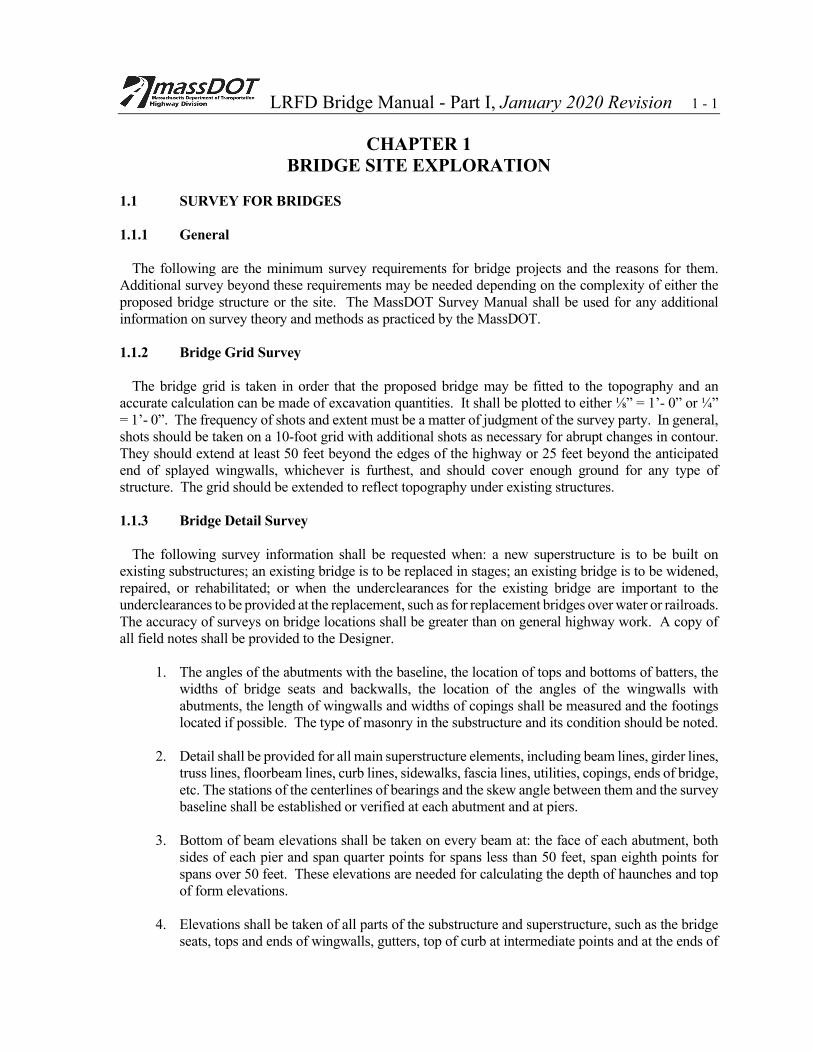
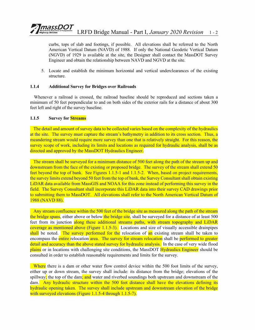
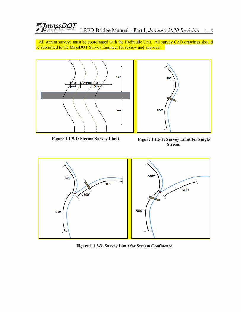
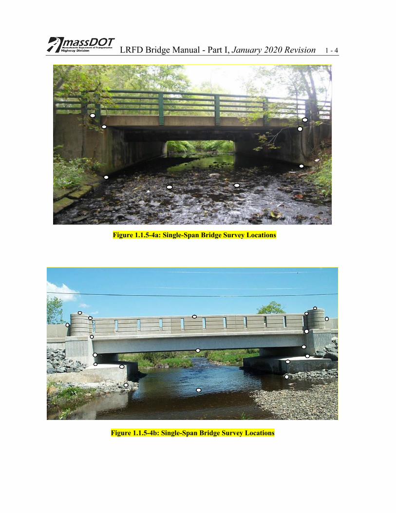
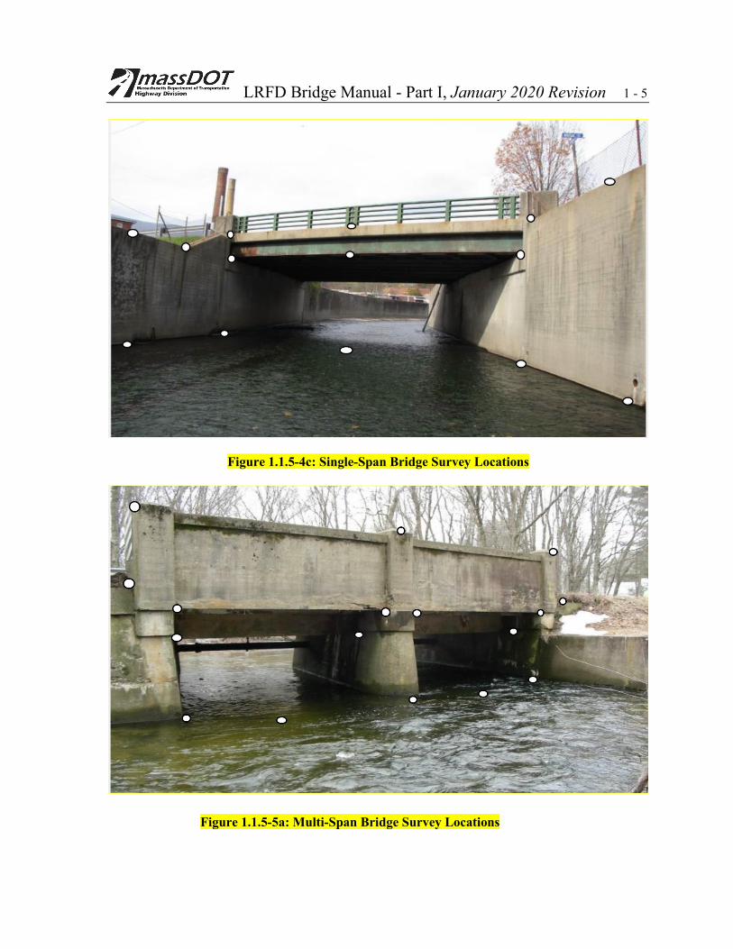
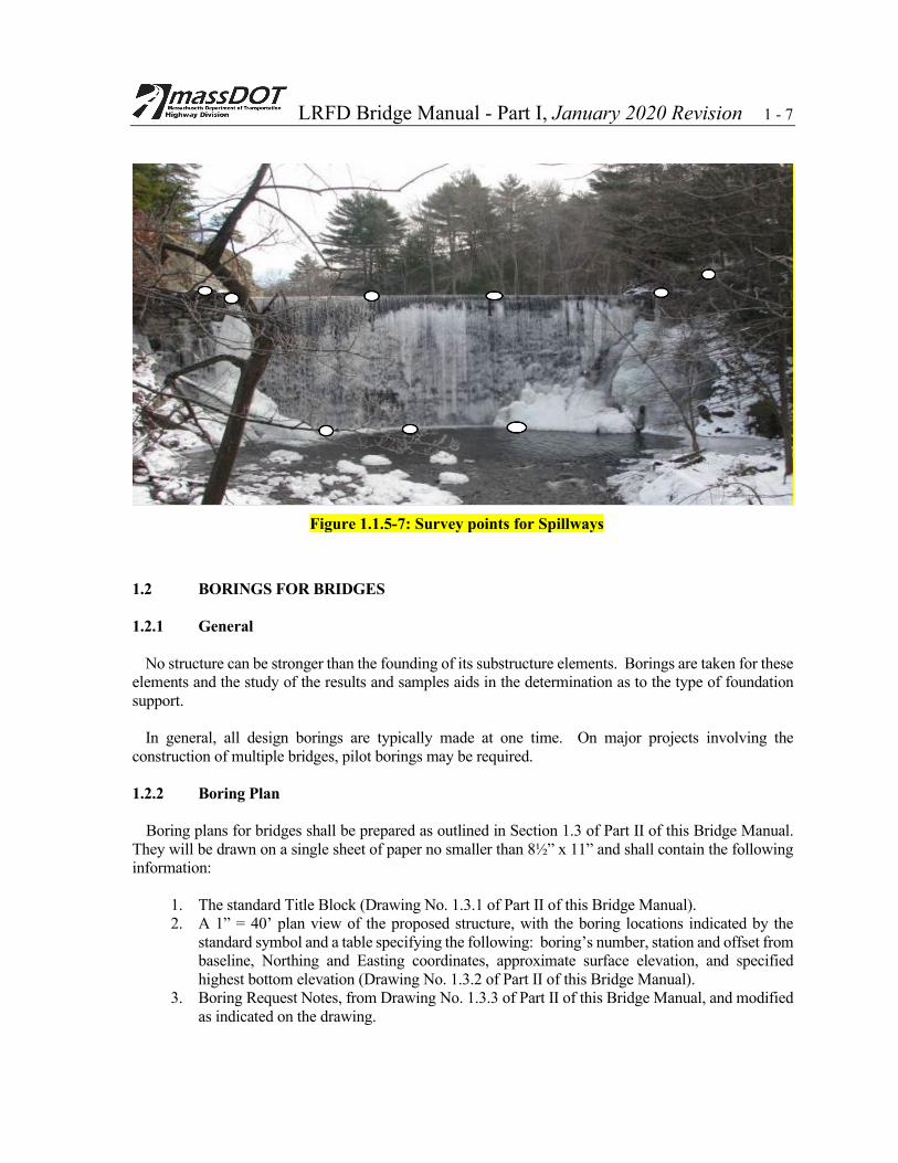
1.1.4 Additional Survey for Bridges over Railroads Whenever a railroad is crossed, the railroad baseline should be reproduced and sections taken a minimum of 50 feet perpendicular to and on both sides of the exterior rails for a distance of about 300 feet left and right of the survey baseline. 1.1.5 Survey for Streams The detail and amount of survey data to be collected varies based on the complexity of the hydraulics at the site. The survey must capture the stream’s bathymetry in addition to its cross section. Thus, a meandering stream would require more survey than one that is relatively straight. For this reason, the survey scope of work, including its limits and locations as required for hydraulic analysis, shall be as directed and approved by the MassDOT Hydraulics Engineer. The stream shall be surveyed for a minimum distance of 500 feet along the path of the stream up and downstream from the face of the existing or proposed bridge. The survey of the stream shall extend 50 feet beyond the top of bank. See Figures 1.1.5-1 and 1.1.5-2. When, based on project requirements, the survey limits extend beyond 50 feet from the top of bank, the Survey Consultant shall obtain existing LiDAR data available from MassGIS and NOAA for this zone instead of performing this survey in the field. The Survey Consultant shall incorporate this LiDAR data into their survey CAD drawings prior to submitting them to MassDOT. All elevations shall refer to the North American Vertical Datum of 1988 (NAVD 88). Any stream confluence within the 500 feet of the bridge site as measured along the path of the stream the bridge spans, either above or below the bridge site, shall be surveyed for a distance of at least 500 feet from its junction along these additional streams paths, with stream topography and LiDAR coverage as mentioned above (Figure 1.1.5-3). Locations and size of visually accessible drainpipes shall be noted. The survey performed for the relocation of an existing stream shall be taken to encompass the entire relocation area. The survey for stream relocation shall be performed to greater detail and accuracy than the above stated survey for hydraulic analysis. In the case of very wide flood plains or in locations with challenging site conditions, the MassDOT Hydraulics Engineer should be consulted in order to establish reasonable requirements and limits for the survey. Where there is a dam or other water flow control device within the 500 foot limits of the survey, either up or down stream, the survey shall include: its distance from the bridge; elevations of the spillway; the top of the dam; and water and riverbed soundings both upstream and downstream of the dam. Any hydraulic structure within the 500 feet distance shall have the elevations defining its hydraulic opening taken. The survey shall include upstream and downstream elevation of the bridge with surveyed elevations (Figure 1.1.5-4 through 1.1.5-7).
LRFD Bridge Manual - Part I, January 2020 Revision 1 - 3 All stream surveys must be coordinated with the Hydraulic Unit. All survey CAD drawings should be submitted to the MassDOT Survey Engineer for review and approval.
Figure 1.1.5-1: Stream Survey Limit Figure 1.1.5-2: Survey Limit for Single Stream
Figure 1.1.5-3: Survey Limit for Stream Confluence
LRFD Bridge Manual - Part I, January 2020 Revision 1 - 4
Figure 1.1.5-4b: Single-Span Bridge Survey Locations
Figure 1.1.5-4a: Single-Span Bridge Survey Locations
LRFD Bridge Manual - Part I, January 2020 Revision 1 - 5
Figure 1.1.5-4c: Single-Span Bridge Survey Locations
Figure 1.1.5-5a: Multi-Span Bridge Survey Locations
LRFD Bridge Manual - Part I, January 2020 Revision 1 - 6
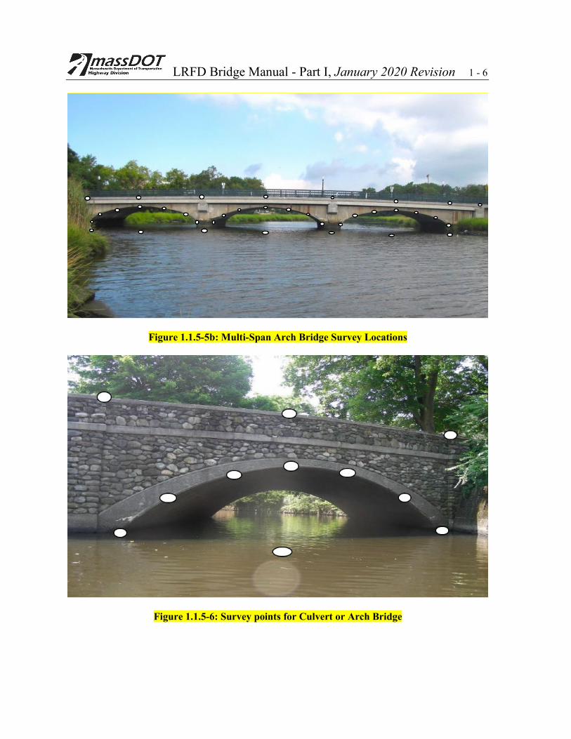
Figure 1.1.5-5b: Multi-Span Arch Bridge Survey Locations
Figure 1.1.5-6: Survey points for Culvert or Arch Bridge
LRFD Bridge Manual - Part I, January 2020 Revision 1 - 7
1.2 BORINGS FOR BRIDGES 1.2.1 General No structure can be stronger than the founding of its substructure elements. Borings are taken for these elements and the study of the results and samples aids in the determination as to the type of foundation support. In general, all design borings are typically made at one time. On major projects involving the construction of multiple bridges, pilot borings may be required. 1.2.2 Boring Plan Boring plans for bridges shall be prepared as outlined in Section 1.3 of Part II of this Bridge Manual. They will be drawn on a single sheet of paper no smaller than 8½” x 11” and shall contain the following information:
1. The standard Title Block (Drawing No. 1.3.1 of Part II of this Bridge Manual). 2. A 1” = 40’ plan view of the proposed structure, with the boring locations indicated by the
standard symbol and a table specifying the following: boring’s number, station and offset from baseline, Northing and Easting coordinates, approximate surface elevation, and specified highest bottom elevation (Drawing No. 1.3.2 of Part II of this Bridge Manual).
3. Boring Request Notes, from Drawing No. 1.3.3 of Part II of this Bridge Manual, and modified as indicated on the drawing.
Figure 1.1.5-7: Survey points for Spillways
LRFD Bridge Manual - Part I, January 2020 Revision 1 - 8 An Adobe Acrobat format (PDF) copy of the proposed boring plan shall be submitted to the MassDOT Project Manager who will transmit hard copies of the boring plan, along with a cover letter requesting that borings be taken, to the Geotechnical Section and to the Bridge Section for review. The Geotechnical Section shall review the proposed boring plan in the office and in the field, shall accept the Bridge Section’s comments, and shall transmit all comments to the Designer for boring plan modification and resolution. The Designer shall then forward the revised (if applicable) boring plan to the Geotechnical Section for acceptance. Upon acceptance, the Geotechnical Section shall initiate and conduct the subsurface investigation through its drilling contractor. 1.2.3 Definitions 1.2.3.1 Pilot Borings. Major projects involving the construction of multiple bridges may require pilot borings, which are those made during the preliminary stage of a project. These borings shall be located by the Designer to yield only sufficient soil information to enable the Designer to:
1. Prepare a preliminary foundation assessment. 2. Fix the profile, alignment of the highway, and position of the structures. 3. Prepare a preliminary cost of the project.
1.2.3.2 Design Borings. Design borings are made to furnish all subsurface data and soil samples required by the Designer to complete the design of the project. Depending on the situation, design borings may either be taken all at once or they may consist of control and complementary borings. Design borings are typically taken after the profile and alignment of the road have been set and the structure type has been advanced sufficiently to identify the number, alignment and location of all substructure units. Borings in the pilot set that fit into the pattern of the design borings shall not be duplicated. 1.2.3.3 Control Borings. Control borings are the initial design borings. The results obtained from control borings are reported immediately to the Designer so that, at each area and location, the depth to which all remaining complementary borings should be taken can be determined. 1.2.3.4 Complementary Borings. Complementary borings are the remaining design borings required for design and construction purposes. They are made after an analysis of the results obtained from the control borings, to the depth specified by the Engineer. Usually, the Designer and the MassDOT's Geotechnical Section and/or Bridge Section jointly review the results of the control borings to determine the depths of the structural complementary borings. Complementary borings are not used for a pilot boring program. 1.2.4 Depth and Location 1.2.4.1 Pilot Borings. Depth: For structures, the specified highest bottom elevation shall be set 10 feet below the preliminary footing elevation at the boring location. Each boring shall be made to the specified highest bottom elevation or to refusal, whichever is deeper. Refusal is defined as 120 blows for 12 inches (or fraction of 12 inches) of penetration by using the Standard Penetration Test (SPT). If rock is encountered above highest bottom elevation, a 10-foot long rock core is taken and the borehole is terminated. Location: One boring per bridge site. Consideration of a rock core should be made at this time if rock would influence the foundation design.
LRFD Bridge Manual - Part I, January 2020 Revision 1 - 9 1.2.4.2 Design Borings. Depth: For structures, the specified highest bottom elevation shall be set at the depth equal to two footing widths below the preliminary footing elevation at the boring location. For perched abutments, the specified highest bottom elevation shall be set 15 feet below existing ground. At least one boring shall be made to bedrock and a 10-foot long core taken at each bridge location. Where a viaduct of considerable length is to be designed, every other pier may have one boring made to bedrock, if deemed necessary by the Engineer. Where structure foundations may be pile or drilled shaft supported, one boring shall be made to bedrock under each substructure unit. Location: Borings shall be taken for every bridge, metal arch, box culvert with a span greater than 8 feet, retaining wall, and "highmast lighting foundation". Borings may be required for sign supports. For smaller structures, engineering judgment should govern. One boring shall be made at each end of each pier or abutment and at the outer end of each wingwall longer than 30 feet. Where piers and/or abutments are more than 100 feet long, additional borings may be required. These additional borings could consist of both control and complementary borings, as specified by the Designer. For retaining walls up to 100 feet in length, at least one boring shall be taken at each end of the wall. For walls longer than 100 feet, borings shall be spaced no more than 100 feet apart. Wall borings shall be alternately control and complementary. For culverts up to 50 feet in length, two borings will be required. For culverts longer than 50 feet, three borings will be required. The preceding description is given as a guide and should not pre-empt sound engineering judgment. Likewise, the depth to which borings are carried may vary, depending on design requirements. Where utilities are present, the borings shall be accurately located no closer than 5 feet from the nearest edge of the utility. 1.2.5 Other Subsurface Exploratory Requirements 1.2.5.1 The additional subsurface explorations outlined below will be included as part of the boring program. Any laboratory test program on the recovered boring samples required by the Designer which is to be done at an outside testing laboratory shall be approved by MassDOT before any work is done. Upon completion of all boring operations, the samples shall be delivered to the MassDOT storage facilities or as directed by the Geotechnical Engineer. No soils and/or rock samples shall be removed from the referenced facilities without formal approval of the Geotechnical Engineer. 1.2.5.2 Under certain conditions, test pits may be needed to disclose certain features of existing structures that may be retained. Test pits shall be dug to establish the elevations of the top and bottom of the footing toe as well as the projection of the toe from the face of the abutment or wall. A minimum of two test pits shall be dug at each abutment, one approximately at each end of the abutment. 1.2.5.3 Exploratory probes will be taken, in conjunction with coring through concrete decks/abutments and horizontal cores, if required, for all abutments and walls which may be retained and for which accurate plans do not exist. These exploratory procedures are needed to determine the cross sectional geometry of
LRFD Bridge Manual - Part I, January 2020 Revision 1 - 10 the wall, such as width, batter and footing thickness, from which the re-use potential of the structure can be evaluated. Provisions for this type of investigation will be included as part of the boring program. 1.2.5.4 If a clay stratum or other compressive material is encountered, in-situ tests and/or undisturbed samples may be required for laboratory tests and analysis. Generally, this type of work is accomplished in the complementary boring program after the results of the control borings are reviewed. 1.2.6 Ground Water Observation Wellpoint Ground water level as reported during a soil-test boring operation may not be accurate, since the water level in a test boring may not have had sufficient time to stabilize or may be affected by the use of water in the drilling process. When a study of the pilot or control borings indicates that an excavation in granular soil must be made below ground-water-level, observation wellpoints should be installed. Not more than one (1) observation wellpoint should be installed at a bridge except with prior approval of the Engineer. Unless otherwise directed, the bottom of the point shall be located approximately 10 feet below the proposed bottom of footing. District personnel will measure and report water levels weekly for the first month and monthly thereafter, to the Engineer, unless more frequent readings are required. This information is to be tabulated on the Sketch Plans and Construction Drawings (see Paragraph 2.7.3.3 for Sketch Plans and Paragraph 4.2.2.3 for Construction Drawings). 1.2.7 Inaccessible Boring Locations Because of certain physical conditions, such as existing buildings, overhead wires, underground utilities, or because of problems with abutters, boring crews may have no access and certain borings specified for the structure cannot be taken. In such cases, the additional required borings may be included in the construction contract. This allows the successful bidder for the contract to take these additional borings without interference, since the project site must be cleared of all structures prior to commencing construction.
The additional borings shall be examined in the Bridge Section to determine if any changes will be required in the design of the foundations. The estimated linear footage of the borings and their cost shall be included in the Designer's estimate. The location of these additional borings shall be shown on the contract plans. It should be noted, however, that every possible effort should be made to obtain the required substructure information during the design stage. 1.2.8 Presentation of Sub-Surface Exploration Data All borings, test pits, or seismic information that have been taken must appear on the plans, even though some of the borings may be exploratory. This is true even though some of the borings are taken for one site and later the line is changed so that new borings are required. It is mandatory that borings for both lines be shown on the plans. The exact logs, as specified in the boring contract, must be shown on the plans. If the logs are transcribed on plan sheets, the transcriptions must copy all information exactly as it appears on the logs, including any abbreviations and misspellings. It is not necessary to show the blow count for driving the casing. Data relative to core recovery shall be shown on the boring log. It is the responsibility of the
LRFD Bridge Manual - Part I, January 2020 Revision 1 - 11 boring contractor to accurately describe the soils obtained with the sampler. In printing the description of soils, abbreviations shall be avoided. The elevations of ground water level at the completion of the boring, unless otherwise specified on the log, shall be shown on the boring log. This elevation may be of great importance in order to determine water control measures for constructing the footing in the dry. The bottom (top, if on rock) of the proposed footing of each element of the substructure shall be plotted adjacent to the appropriate boring log. Borings shall be plotted in groups as they apply to substructure units for ready reference. In the case of a trestle, the bottom of each pile cap shall be shown on the boring logs.
The estimated tip or length of rock socket of piles or drilled shafts shall be plotted adjacent to the appropriate boring log. Boring results shall be plotted to true relative elevation to a scale of not less than ⅛” = 1’- 0”. Deep borings may offset or show discontinuity only in the event that they cannot be completed in one column. When posting boring logs on the plans the Designer shall post both depth and elevation at each change in strata. 1.3 HYDROLOGY AND HYDRAULICS 1.3.1 Introduction
The purpose of this section is to provide guidance regarding the performance of hydraulic studies for MassDOT bridges. These studies are required under the Federal Highway Administrations (FHWA) Federal Aid Policy Guide, 23 CFR 650A and the latest edition of the AASHTO LRFD Bridge Design Specifications, Article 2.6. The detail of hydraulic studies should be commensurate with the significance of the structure to the transportation network and with the risks associated with its failure. The guidelines contained herein are not intended to address all contingencies associated with the hydraulic design of bridge structures. In atypical situations, early consultation with the MassDOT Hydraulic Engineer is recommended. 1.3.2 Hydraulic Design Criteria
Hydraulic design criteria to be used for MassDOT bridges are enumerated below. These criteria are
consistent with the content of Article 2.6 of the AASHTO LRFD Bridge Design Specifications and are subject to change when conditions so dictate as approved by MassDOT.
1. To the extent practicable, proposed bridges shall not cause any significant change in the
affected waterway’s existing flooding regime over the range of discharges considered. 2. Proposed bridges crossing waterway’s which have established National Flood Insurance
Program (NFIP) Special Flood Hazard Area (SFHA) Zone delineations, shall conform to applicable NFIP SFHA development performance standards as listed in Title 44 Code of Federal Regulations, Section 60, Part 3 [44 CFR 60 (3)]. In particular, proposed bridges crossing waterways with existing NFIP regulatory floodway delineations should not cause any increase in waterway’s base flood elevation (BFE) profile – or result in any unapproved
LRFD Bridge Manual - Part I, January 2020 Revision 1 - 12
increases to the width of the waterway’s effective delineation- anywhere in the affected community. If a proposed bridge, when constructed, will not meet applicable NFIP SHFA development performance standards, the Designer shall file a Conditional Letter of Map Revision (CLOMR) and, if warranted, a Letter of Map Revision (LOMR) with the Federal Emergency Management Agency (FEMA) as specified in 44 CFR 60 (3).
3. The “No-Rise” Floodway Encroachment Review procedure outlined in Subsection 1.3.5 shall
be used determine the degree to which proposed bridges crossing Regulatory Floodways meet applicable NFIP base floodplain development performance standards.
4. Proposed bridges crossing or located in close proximity to municipal or state owned dams
under the jurisdiction of the Massachusetts Department of Conservation and Recreation (MassDCR) Office of Dam Safety or an NFIP-certified flood control levee under the jurisdiction of the US Army Corps of Engineers, New England District (USACOE NED) Office of Levee Safety shall be designed so as to avoid or minimize any adverse impact on structural integrity of the affected flood control system.
5. Preferably, piers and abutments shall be placed and oriented parallel to the flow of the stream
in order to minimize flow disruption and potential scour. 6. Bridge foundations shall be evaluated for scour vulnerability considering flood return
frequencies up to 500 years. Pertinent scour evaluation guidelines are presented in Subsections 1.3.3, 1.3.4 and 1.3.6.
7. Optimally, new and replacement bridge superstructures should be configured so as to provide
2 feet of freeboard between the hydraulic design flood water surface elevation and the proposed superstructure low chord to allow for the passage of debris and ice. Where this is not feasible, the clearance should be established by the Designer based on a level of bridge flood damage protection approved by MassDOT. Proposed bridges spanning navigational channels regulated by the US Coast Guard (USCG) shall provide a navigational channel opening with vertical and horizontal clearances conforming to the effective USCG Section 10 Permit requirements.
8. Construction of proposed bridges shall have minimal impact to local and regional ecosystems
and preserve the natural and beneficial values served by adjacent floodplains. 9. To the extent practicable, the design of new and replacement bridge waterway openings shall
conform to applicable sections of the Massachusetts Stream Crossing Standards. The Designer is referred to MassDOT Design of Bridges and Culverts for Wildlife Passage at Freshwater Streams (Reference 16) and FHWA Hydraulic Engineering Circular Number 26, “Culvert Design for Aquatic Organism Passage” (Reference 15), for more definitive design guidance.
10. Design choices should support costs for construction, maintenance and operation, including
probable repair and reconstruction and potential liability that are affordable.

LRFD Bridge Manual - Part I, January 2020 Revision 1 - 13 1.3.3 Hydraulic Study Procedure
Although each individual crossing site is unique, the following procedure should be applied to MassDOT bridges unless indicated otherwise by MassDOT. 1.3.3.1 Preliminary Data Collection Preliminary data collection includes the following:
A. Stream Survey
• Stream survey limits established by the MassDOT Hydraulic Engineer • Survey request shall be initiated by MassDOT Project Manager • Field survey operations must be conducted in a manner consistent with the guidelines
set forth in Section 1.1.5 of the LRFD Bridge Manual and the MassDOT field Survey guidelines and baseplan requirements for survey and design consultants.
B. Stream Bed Sediment Particle Size Analysis
• Stream bed sediment sample locations as described in Paragraph 1.3.3.5 D of this Bridge Manual
• Consultant shall obtain sediment samples, perform ASTM D422 Sieve Analyses Test (ASTM D422), and provide MassDOT Hydraulic Section the particle size distribution results applicable to each sample location
C. National Flood Insurance Program (NFIP) Flood Insurance Study (FIS) Data
• NFIP FIS data request form shall be completed by MassDOT Hydraulic Engineer • MassDOT Project Manager or consultant shall submit the completed NFIP FIS data
request and all required administrative fees to the Federal Emergency Management Agency (FEMA) Engineering library.
D. Tidal Monitoring (for coastal zone crossing)
• Consultant shall deploy and obtain at least two continuous data logging pressure-transducer tide gages within the affected reach of the crossed waterway;
• At least one gage should be located near the mouth of the waterway to assure capture local off-shore (un-damped) tidal signal;
• Ideally, gages should be installed within 100 feet upstream and downstream of the bridge crossing location;
• Each instrument’s location and elevation must be accurately surveyed with all measurements referenced to known benchmarks and corrected to the project’s horizontal and vertical datum;
• Each instrument should be deployed for a 30-day period to capture the influence of a full lunar cycle and at a depth sufficient to assure constant instrument submersion over that deployment period;
• Each instrument should be programmed to record data at 10-minute intervals;
LRFD Bridge Manual - Part I, January 2020 Revision 1 - 14
• The consultant should download the information recorded by each deployed instrument, check the raw data for accuracy, process the same into tidal elevation time series data set worksheets compatible with MS Excel, and submit the final worksheets to the MassDOT Hydraulic Section.
E. Bridge Type Selection Worksheet
• Proposed alternative(s) with sketches showing dimensions and elevations of the bridge opening and substructure details of the bridge should be provided to MassDOT Hydraulic Section prior to the start of hydraulic analysis.
F. Temporary Water Control Measures
• When the construction of bridge substructures in the water requires cofferdams and/or
water control measures that will create temporary restrictions to the normal flow of water, the Designer will provide the MassDOT Hydraulic Section details of these restrictions prior to the preparation of the Construction Drawings. This information shall include the estimated size of the cofferdam and/or the amount of channel that the water control measures will close off for each stage of construction as well as the length of time they are estimated to be in place. The Hydraulic Section will provide the Designer with the hydraulic criteria and the estimated flood elevation with the water control measure in place for each design stage based on the flood return periods specified in Paragraph 1.3.3.4 E.
1.3.3.2 Data Collection. The purpose of this phase is to accumulate and refine the technical database required to support the hydrologic/hydraulic analysis to be performed within the project hydraulic study. The effort expended should be commensurate with the significance and complexity of the project. 1.3.3.3 Hydrologic Analysis
A. Recommended hydrologic computational methods include the following:
• USGS National Streamflow Statistics (NSS) Program (Reference 27) • NRCS Technical Releases 20 and 55 (References 17 and 19). • USACOE HEC-HMS (Reference 23) • Estimating the Magnitude of Peak Flows for Steep Gradient Streams in New England
(Reference 29) • USGS Scientific Investigation Report 2016-5156 (Reference 30)
Other standard engineering methods may be used subject to approval by the MassDOT Hydraulic Engineer. B. In general, results from several methods should be compared (not averaged) so as to identify the discharges that best reflect local project conditions with the reasons documented.
C. At a minimum, the Designer should estimate the crossed waterway’s 1 %, 2%, 1%, and 0.2 % annual chance peak discharges. Also, known as the 10-, 50-, 100-, and 500-year return frequency peak discharges.
LRFD Bridge Manual - Part I, January 2020 Revision 1 - 15
D. Hydraulic Design Flood Frequency. The hydraulic design flood frequency is the annual chance (in percentage) peak discharge (in cubic feet per second) the bridge waterway opening must safely convey. The overtopping flood and the hydraulic design frequency flood may vary widely depending on the grade, alignment and classification of the road and the characteristics of the water course and floodplain (see Subsection 1.3.4, Hydraulic and Scour Design Flood Selection Guidelines).
E. Designers performing hydraulic studies for proposed bridges at existing NFIP Regulatory Floodway crossings must use the crossed waterway’s base (100-year) flood discharge established for the bridge location in the applicable NFIP Flood Insurance Study (FIS) to perform the required “No Rise” Floodway Encroachment Review (see Subsection 1.3.5) F. The influence of the tide should be considered in all hydraulic adequacy/scour safety assessments performed for MassDOT bridges crossing tidal waterways. The Designer should note that flooding at tidal bridge locations could be the result of the concurrent occurrence of a riverine flood and a tidal flood surge generated by a single metrological event, such as a tropical hurricane or a “Northeaster” type coastal storm. Accordingly, prior to employing such as “mixed population” tidal flood as a hydraulic or scour design flood event , the Designer should estimate the flood’s joint annual exceedance probability- to assure the flood’s return frequency is appropriate for its intended use.
G. The NOAA Atlas 14, Precipitation Frequency Data Server (PFDS) web application shall be used as the source of precipitation frequency estimates in Massachusetts.
1.3.3.4 Hydraulic Analysis
A. Water surface profile computer programs such as USACOE HEC-RAS (Reference 24) should be used to perform required bridge hydraulic design to extract hydraulic parameters for scour safety computations, unless indicated otherwise by MassDOT. The use of 2-D hydraulic modeling using SMS:SRH-2D or HEC-RAS 2D is preferred for complex projects. B. Hydraulic performance for existing and proposed conditions under at least the 10 %, 2%, 1%, and 0.2 % annual chance peak discharges should be evaluated for all project alternatives considered in the bridge type selection process. C. A “No Rise” Floodway Encroachment Review- performed in accordance with the guidelines presented in Subsection 1.3.5- is required for all proposed bridge replacement projects encroaching on effective NFIP Regulatory Floodway delineations. D. At tidal crossing sites, the time dependent correlation between tide stage, discharge, and velocity must be evaluated. The detail of this hydrodynamic analysis should be commensurate with the functional significance of the structure, the capital risks associated with its failure, and the complexity of site hydrodynamics. In most cases, the use of the one-dimensional hydrodynamic computer application UNET nested within the USACOE HEC-RAS computer program (Reference 24) is recommended. However, complex, multi-span structures (esp. Interstate or numbered State Highway bridges) crossing major tidal waterways may warrant assembly and calibration of a two-dimensional finite element hydrodynamic model (References 7 and 22). Early consultation with the MassDOT Hydraulic Engineer to determine an appropriate level of project specific hydrodynamic analysis is recommended.
LRFD Bridge Manual - Part I, January 2020 Revision 1 - 16
E. The Designer should use the crossed waterway’s 2-year flood as the design flood event for temporary construction-related structures that will be in place for one year or less. The Designer should use the waterway’s 5- year flood as the design flood event for temporary structures that will be in place for not more than two years- and the 10-year flood for temporary structures that will in place for more than two years.
1.3.3.5 Scour/Stability Analysis
A. Scour Safety assessments must be performed as part of all MassDOT bridge hydraulic studies. These assessments should be performed in a manner consistent with the general guidelines set forth in the FHWA's Hydraulic Engineering Circular Nos. 18 (HEC-18), "Evaluating Scour at Bridges" (Reference 10), HEC-20, "Stream Stability at Highway Structures" (Reference 11), HEC-23, “Bridge Scour and Stream Instability Countermeasures (Reference 12), and HEC-25, “Highways in the Coastal Environment” (Reference 14). The Designer should use the NCHRP 24-20 Abutment Scour Approach to estimate local abutment depths (Reference 10, section 8.6.3). For culverts, estimating the scour hole geometry should be performed in a manner consistent with the general guidelines set forth in the FHWA’s Hydraulic Engineering Circular No. 14 (HEC-14), “Hydraulic Design of Energy Dissipators for Culverts and Channels” (Reference 9). B. There are many sources of uncertainty involved in the process of estimating potential scour depths along bridge foundations (see Reference 10, Sections 2.1 and 2.3.3). Accordingly, it is the responsibility of the Designer to use sound engineering judgment to evaluate the reasonableness of any computed scour depth with due consideration to build and natural armoring of the local streambed, the location and condition of existing scour countermeasures, the flood conveyance capacity and geometry of the existing waterway opening and upstream approach channel, the topographic relief and vegetated cover of the upstream overbank floodplain, present evidence of scour (or lack thereof) along the existing structure’s foundation, and the scour resilience demonstrated by the existing structure’s foundation during major flood events that have occurred over the structure’s service life. If a scour estimate is determined to be unreasonable, the Designer should modify the original scour estimate to more closely correspond to observed or recorded site scour conditions. The basis for modifying a computed scour depth should be clearly documented within the project administrative record. C. Pursuant to Subsection 3.2.9 of Chapter 3 of this Bridge Manual, the Designer should use the guidelines set forth in Subsection 1.3.4 to determine appropriate return frequencies for the project design flood and check flood scour discharges. Nonetheless, the waterway’s incipient overtopping flood discharge should be used in the project scour safety analysis, if less than the design flood and/or the check flood scour discharges as it may create higher scour depths just before overtopping.
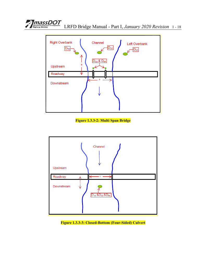
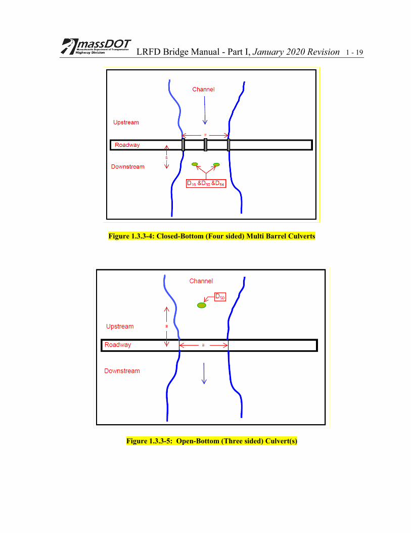
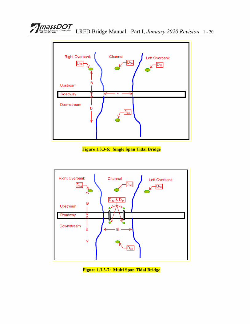
D. The following are guidelines for locations of soil samples and tests to be conducted for scour evaluations for Riverine and Tidal Bridges
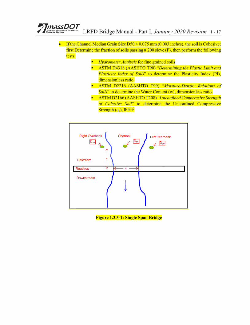
• The sieve size and the location of the samples to be collected for a given type of structure are as indicated in Figures 1.3.3.3-1 through 1.3.3.3-7.
• Perform ASTM D422 (AASHTO T88) “Particle Size Analysis of Soils” to determine the Grain Size of D16, D50 and D84 (mm) (ft) for samples from the approach section, downstream section and for the samples collected from the upstream face of the piers as indicated in the figures
LRFD Bridge Manual - Part I, January 2020 Revision 1 - 17
• If the Channel Median Grain Size D50 < 0.075 mm (0.003 inches), the soil is Cohesive; first Determine the fraction of soils passing # 200 sieve (F), then perform the following tests:
Hydrometer Analysis for fine grained soils ASTM D4318 (AASHTO T90) “Determining the Plastic Limit and
Plasticity Index of Soils” to determine the Plasticity Index (PI), dimensionless ratio.
ASTM D2216 (AASHTO T99) “Moisture-Density Relations of Soils” to determine the Water Content (w), dimensionless ratio.
ASTM D2166 (AASHTO T208) “Unconfined Compressive Strength of Cohesive Soil” to determine the Unconfined Compressive Strength (qu), lbf/ft2
Figure 1.3.3-1: Single Span Bridge
LRFD Bridge Manual - Part I, January 2020 Revision 1 - 18
Figure 1.3.3-2: Multi Span Bridge
Figure 1.3.3-3: Closed-Bottom (Four-Sided) Culvert
LRFD Bridge Manual - Part I, January 2020 Revision 1 - 19
Figure 1.3.3-4: Closed-Bottom (Four sided) Multi Barrel Culverts
Figure 1.3.3-5: Open-Bottom (Three sided) Culvert(s)
LRFD Bridge Manual - Part I, January 2020 Revision 1 - 20
Figure 1.3.3-6: Single Span Tidal Bridge
Figure 1.3.3-7: Multi Span Tidal Bridge

LRFD Bridge Manual - Part I, January 2020 Revision 1 - 21
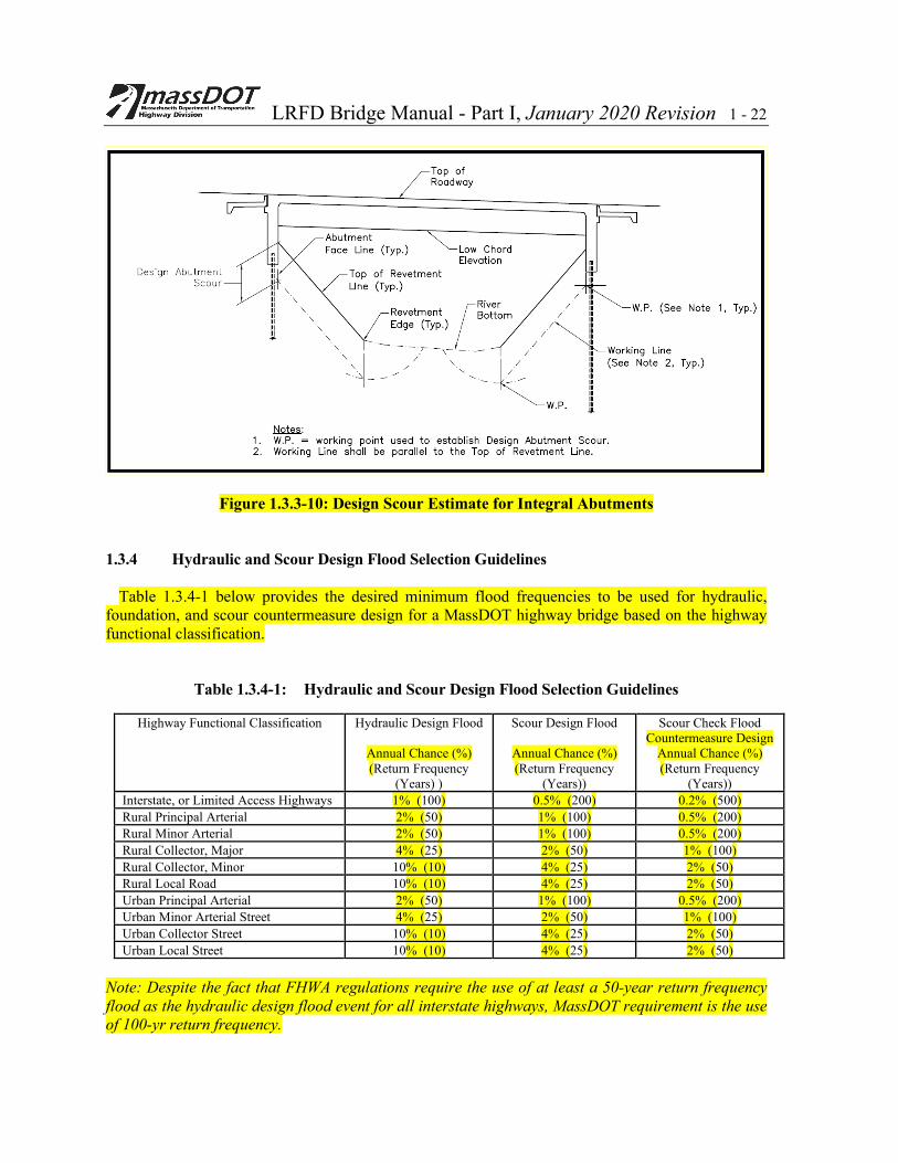
E. The following Figures illustrate Design Abutment Scour and Total Pier Scour Estimate for Vertical Abutments and Piers (Figure 1.3.3-8), Design Abutment Scour Estimate for Abutments with Fill in Front (Figure 1.3.3-9), and Design Abutment Scour Estimate for Integral Abutments (Figure 1.3.3-10).
Figure 1.3.3-8: Design Abutment Scour and Total Pier Scour Estimate for Vertical Abutments and Piers
Figure 1.3.3-9: Design Scour Estimate for Abutments with Fill in Front
LRFD Bridge Manual - Part I, January 2020 Revision 1 - 22
Figure 1.3.3-10: Design Scour Estimate for Integral Abutments 1.3.4 Hydraulic and Scour Design Flood Selection Guidelines
Table 1.3.4-1 below provides the desired minimum flood frequencies to be used for hydraulic, foundation, and scour countermeasure design for a MassDOT highway bridge based on the highway functional classification.
Table 1.3.4-1: Hydraulic and Scour Design Flood Selection Guidelines
Highway Functional Classification Hydraulic Design Flood
Annual Chance (%) (Return Frequency
(Years) )
Scour Design Flood
Annual Chance (%) (Return Frequency
(Years))
Scour Check Flood Countermeasure Design
Annual Chance (%) (Return Frequency
(Years)) Interstate, or Limited Access Highways 1% (100) 0.5% (200) 0.2% (500) Rural Principal Arterial 2% (50) 1% (100) 0.5% (200) Rural Minor Arterial 2% (50) 1% (100) 0.5% (200) Rural Collector, Major 4% (25) 2% (50) 1% (100) Rural Collector, Minor 10% (10) 4% (25) 2% (50) Rural Local Road 10% (10) 4% (25) 2% (50) Urban Principal Arterial 2% (50) 1% (100) 0.5% (200) Urban Minor Arterial Street 4% (25) 2% (50) 1% (100) Urban Collector Street 10% (10) 4% (25) 2% (50) Urban Local Street 10% (10) 4% (25) 2% (50)
Note: Despite the fact that FHWA regulations require the use of at least a 50-year return frequency flood as the hydraulic design flood event for all interstate highways, MassDOT requirement is the use of 100-yr return frequency.
LRFD Bridge Manual - Part I, January 2020 Revision 1 - 23 1.3.5 Guidelines for "No-Rise" Encroachment Reviews for Proposed MassDOT Bridges Crossing NFIP Regulatory Floodway Delineations
The essential NFIP Regulatory Floodway development performance standard, as described in 44 CFR, Section 60.3(d)(3), is presented below.
“A community shall prohibit encroachments, including fill, new construction, substantial improvements, and other development within the adopted regulatory floodway unless it has been demonstrated through hydrologic and hydraulic analyses performed in accordance with standard engineering practice that the proposed encroachment would not result in any increase in flood levels within the community during the occurrence of the base flood discharge."
Bridge Designers should use the following procedure to determine project encroachment impact on
existing NFIP Regulatory Floodway delineations.
1. Obtain a copy of input files for the waterway’s currently effective NFIP hydraulic model from FEMA achieves. Pertinent contact information is presented below. A fee will be assessed for providing this data.
FEMA Engineering Library 3601 Eisenhower Ave. Suite 500 Alexandria, Virginia 22304-6426 Fax (703) 960-9125 Note: If the input data files for the effective hydraulic model are not available, the Designer must assemble and calibrate an alternate model. Alternate model cross sections should be developed at the waterway locations at which cross sections were acquired for the NFIP effective model. The alternate model’s cumulative reach lengths should match those of the effective model as closely as possible. The alternate model calibration runs should be performed using FIS peak discharge and flood elevation data as up and downs stream boundary conditions- and with each cross section’s effective flow area set at the currently effective floodway delineation’s horizontal limits. The calibration process should yield an alternate model that reproduces the “with floodway” elevations provided in the community FIS Floodway Data Table within 0.5 ft.
2. Develop a Duplicate Effective Model by uploading the currently effective model’s input data
into the most current release of USACOE HEC-RAS. Calibrate the same as required to reproduce the currently effective BFE profile shown in the FIS within 0.5 ft. The reach domain for the Duplicate Effective Model should extend sufficiently upstream and downstream from the project location to assure the upstream and downstream limits of flood profiles generated by this model “tie into” the currently effective NFIP BFE profile without significant elevation discontinuities (+/- 0.5 feet).
3. Develop an Existing Conditions Model by revising the Duplicate Effective Model to correct
any legacy computer coding errors and incorporating any relevant cross section data reflecting changes in the floodplain that may have occurred since the original effective model was developed (without the proposed project in place). The Regulatory Floodway limits at any new model cross sections should be determined by interpolation of FIS Floodway Table data and DFIRM mapping. The model’s cumulative reach lengths should match those of the
LRFD Bridge Manual - Part I, January 2020 Revision 1 - 24
currently effective model. The base flood simulations performed with the Existing Conditions Model will provide modified effective model BFE and Regulatory Floodway elevation profiles reflecting current existing base floodplain conditions at the proposed project site.
4. Develop a Proposed Condition Model by modifying the Existing Conditions Model to
account for base floodplain feature alterations expected as a result of project implementation. This model must use the currently effective regulatory floodway widths at every model cross section and have cumulative reach lengths that match those of the currently effective model. BFE and Regulatory Floodway elevation profiles are then generated with the Proposed Conditions Model and compared to those of the Existing Conditions Models. For compliance with 44CFR 60.3(d)(3), the Proposed Conditions BFE and Regulatory Floodway elevation profiles must indicate a “no-rise” impact on the same Existing Conditions profiles at every model cross section location.
1.3.6 Hydraulic Study References
1. American Association of State Highway and Transportation Officials (AASHTO), LRFD Bridge Design Specifications, Fifth Edition, 2010
2. AASHTO, Drainage Manual, First Edition, 2014 3. AASHTO, Highway Drainage Guidelines, Fourth Edition, 2007. 4. Chow, V. T. Open-Channel Hydraulics, McGraw–Hill, New York, 1959 5. Deliman, P. N., Ruiz, C. E., Manwaring, C. T., and Nelson, E. J., Watershed Modeling
System Hydrological Simulation Program; Watershed Model User Documentation And Tutorial, ERDC/EL SR-02-1, U.S. Army Engineer Research and Development Center, Vicksburg, MS., 2002.
6. Federal Emergency Management Agency (FEMA), Guidelines and Specifications for Flood
Hazard Mapping Partners, April 2003. 7. Federal Highway Administration (FHWA), FESWMS-2DH, Finite Element Surface Water
Modeling System: Two-Dimensional Flow in a Horizontal Plane, User's Manual, 1996. 8. FHWA, Hydraulic Engineering Circular Number 11, Design of Rip Rap Revetment, HEC-
11, March 1989 9. FHWA, Hydraulic Engineering Circular Number 14, Hydraulic Design of Energy
Dissipators for Culverts and Channels, HEC-14, July 2006 10. FHWA, Hydraulic Engineering Circular Number 18, Evaluating Scour at Bridges, HEC-18,
April 2012. 11. FHWA, Hydraulic Engineering Circular Number 20, Stream Stability at Highway Structures,
HEC-20, April 2012

LRFD Bridge Manual - Part I, January 2020 Revision 1 - 25
12. FHWA, Hydraulic Engineering Circular Number 23, Bridge Scour and Stream Instability Countermeasures, Volumes 1 and 2, September 2009
13. FHWA, Hydraulic Design Series Number 7 (HDS-7), Hydraulic Design Of Safe Bridges
FHWA-Hif-12-018, April 2012 14. FHWA, Hydraulic Engineering Circular Number 25, Highways In The Coastal Environment
Hydraulic Engineering Circular No. 25, June 2008 15. FHWA, Hydraulic Engineering Circular Number 26, Culvert Design for Aquatic Organism
Passage, October 2010 16. MassDOT, Design of Bridges and Culverts for Wildlife Passage at Freshwater Streams, 2010 17. Natural Resources Conservation Service (NRCS), WinTR-20 Computer Program for Project
Formulation Hydrology, Version 1.11, 2009. 18. NRCS, Section 4- Hydrology, National Engineering Handbook, 1972. 19. NRCS, WinTR-55, Urban Hydrology for Small Watersheds, Version 1.00.1, February 2013. 20. Neill, C. R., Guide to Bridge Hydraulics, Roads and Transportation Association of Canada,
2001 Edition. 21. Rosgen, David, Applied River Morphology, Wildland Hydrology, Pagosa Springs, Colorado,
1996. 22. "Surface Water Modeling System” (SMS), Aquaveo LLC, www.aquaveo.com 23. US Army Corps of Engineers (USACOE), Hydrologic Research Center, HEC-HMS,
Hydrologic Modeling System. 24. USACOE, Hydrologic Research Center, HEC-RAS, River Analysis System 25. USACOE, Engineer Waterways Experiment Station, Coastal Engineering Research Center
Shore Protection Manual, 4th ed., 2 vols., 1984 26. USACOE, New England Division (NED), Tidal Flood Profiles, New England Coastline,
March 2012 27. U.S. Geologic Survey (USGS), The National Streamflow Statistics Program: A Computer
Program For Estimating Streamflow Statistics For Ungaged Sites: U.S. Geological Survey Techniques and Methods Report TM Book 4, Chapter A6, 2006.
28. Water Resources Council, Guidelines for Determining Flood Flow Frequency, Bulletin 17B,
Washington, D. C., March 1982. 29. The New England Transportation Consortium, “Estimating the Magnitude of Peak
Flows for Steep Gradient Streams in New England”, November 17, 2010.

LRFD Bridge Manual - Part I, January 2020 Revision 1 - 26
30. Zarriello, P.J., 2017, Magnitude of flood flows at selected annual exceedance probabilities for streams in Massachusetts: U.S. Geological Survey Scientific Investigations Report 2016–5156, 54 p., https://doi.org/10.3133/sir20165156