Embed Size (px)
Citation preview
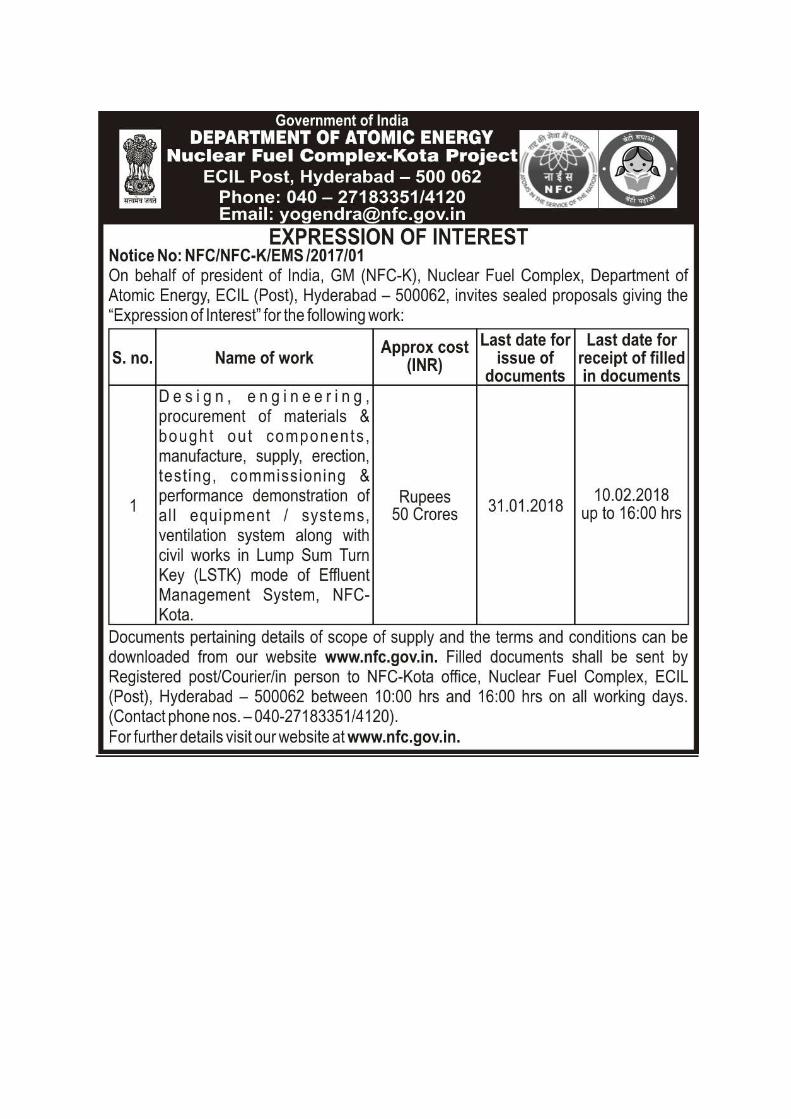
Brief Scope of work for Effluent Management System of Nuclear Fuel Complex-Kota
1
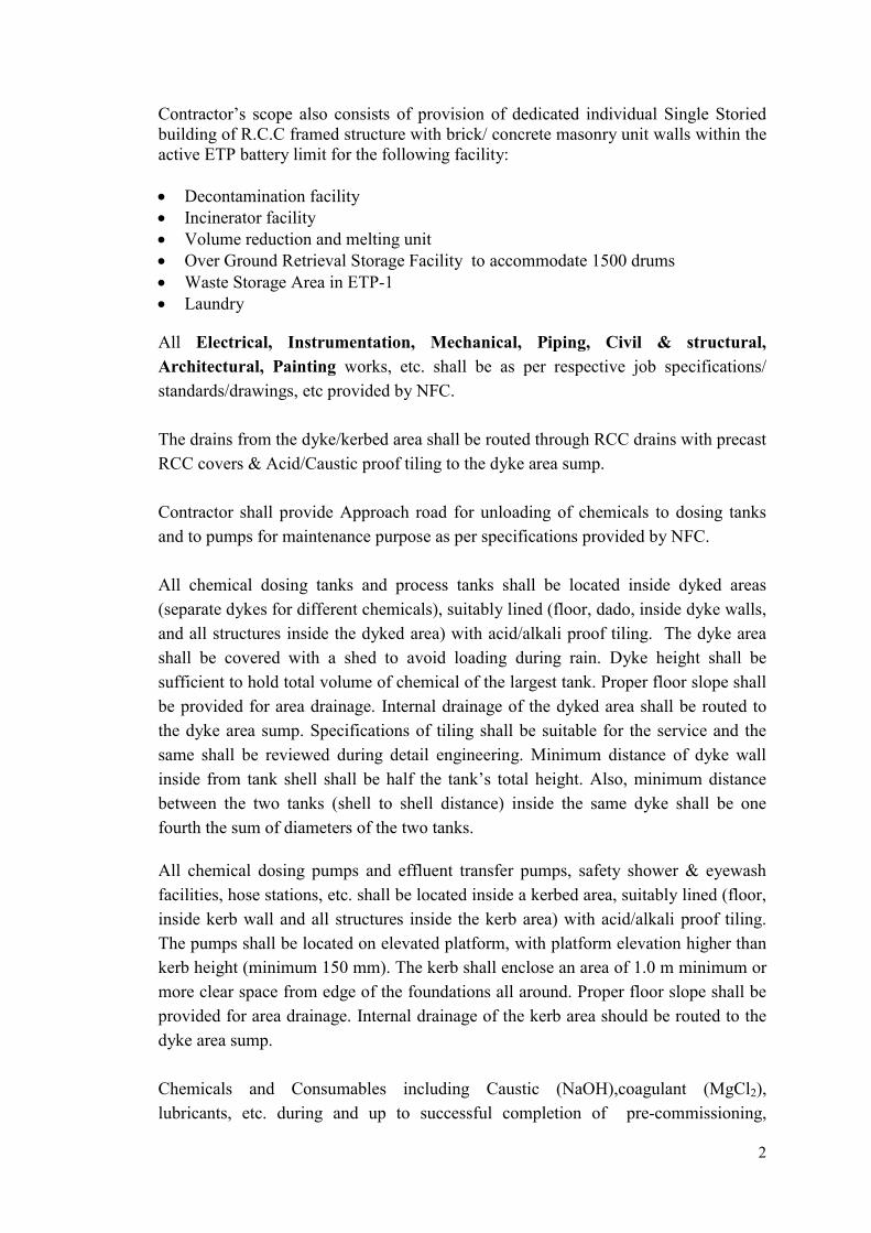
1.0 Introduction M/s Nuclear Fuel Complex (NFC), is in process of setting up new fuel fabrication facilities at Rawatbhata, Kota, Rajasthan which will be called as Nuclear Fuel complex, Kota. The project will be equipped with all the required utilities, infrastructure facilities and the waste management facilities. This document covers the requirement of Effluent Management System (EMS) which consists of
1. Effluent Treatment Plant-1 (Cap. 120 m3/day) & its associated facilities (Active Solid waste Management facility, Laundry and Over ground Retrieval Storage Facility) and building works.
2. Effluent Treatment Plant-2 (Cap. 100 m3/day) & its associated facilities and building works.
3. Sewage Treatment Plant (Cap. 120 m3/day) & its associated facilities and building works.
4. Primary and secondary ventilation systems for EMS. These facilities are configured to handle non process liquid effluent generated from both the active and non-active plant areas of the NFC Kota and active solid waste generated from active plant area of NFC-K.
2.0 Scope of Work and Supply
The Package shall be executed in Lump Sum Turn Key mode including civil works such as RCC Building, civil foundation etc.. The design, engineering, procurement of materials & bought out components, manufacture, supply, erection, testing, commissioning & performance demonstration of all equipment/ systems within the package battery limits shall be in contractor’s scope. The indicative P&IDs of the system, Process Data Sheets of the equipment, Job Specifications, Design Specifications/ requirements and the tentative layout of the concerned areas will provided by NFC . The detailing will be part of contractor’s scope. The scope shall also include preparation of all drawings and documents & obtaining approval from AERB/statutory body. For all the equipments listed in documents or as required to make the plant complete in all respects to deliver the required quantity & quality, the contractor has to supply piping, valves and fittings, instruments, controls, electrical items, etc. and other items as indicated in the document, equipment list, data sheets, P&ID’s etc., or as required to make the plant complete with respect to safe trouble free operation of the plant. Contractor’s scope also consists of provision of one Single Storied building of R.C.C
framed structure with brick/ concrete masonry unit walls for ETP Office within the
active and non active ETP battery limit to house Laboratory Room, Analyzer Room,
Field Operator/control Room, panel room, change room, radiation monitoring room,
Toilet, Drinking water cooler and overhead tank (provided with level gauge, drain,
manhole, overflow, float valve, etc.) all complete as per specifications/ drawings.
2
Contractor’s scope also consists of provision of dedicated individual Single Storied building of R.C.C framed structure with brick/ concrete masonry unit walls within the active ETP battery limit for the following facility: Decontamination facility Incinerator facility Volume reduction and melting unit Over Ground Retrieval Storage Facility to accommodate 1500 drums Waste Storage Area in ETP-1 Laundry
All Electrical, Instrumentation, Mechanical, Piping, Civil & structural,
Architectural, Painting works, etc. shall be as per respective job specifications/
standards/drawings, etc provided by NFC.
The drains from the dyke/kerbed area shall be routed through RCC drains with precast
RCC covers & Acid/Caustic proof tiling to the dyke area sump.
Contractor shall provide Approach road for unloading of chemicals to dosing tanks
and to pumps for maintenance purpose as per specifications provided by NFC.
All chemical dosing tanks and process tanks shall be located inside dyked areas
(separate dykes for different chemicals), suitably lined (floor, dado, inside dyke walls,
and all structures inside the dyked area) with acid/alkali proof tiling. The dyke area
shall be covered with a shed to avoid loading during rain. Dyke height shall be
sufficient to hold total volume of chemical of the largest tank. Proper floor slope shall
be provided for area drainage. Internal drainage of the dyked area shall be routed to
the dyke area sump. Specifications of tiling shall be suitable for the service and the
same shall be reviewed during detail engineering. Minimum distance of dyke wall
inside from tank shell shall be half the tank’s total height. Also, minimum distance
between the two tanks (shell to shell distance) inside the same dyke shall be one
fourth the sum of diameters of the two tanks.
All chemical dosing pumps and effluent transfer pumps, safety shower & eyewash
facilities, hose stations, etc. shall be located inside a kerbed area, suitably lined (floor,
inside kerb wall and all structures inside the kerb area) with acid/alkali proof tiling.
The pumps shall be located on elevated platform, with platform elevation higher than
kerb height (minimum 150 mm). The kerb shall enclose an area of 1.0 m minimum or
more clear space from edge of the foundations all around. Proper floor slope shall be
provided for area drainage. Internal drainage of the kerb area should be routed to the
dyke area sump.
Chemicals and Consumables including Caustic (NaOH),coagulant (MgCl2),
lubricants, etc. during and up to successful completion of pre-commissioning,
3
commissioning, trial runs, stabilization, and for PG test run shall be in the contractor’s
scope of work.
Battery limit isolation valves, spectacle blind etc. on all incoming & outgoing lines
shall be under contractor scope.
The Contractor’s scope will be in accordance with the following requirements which
will be ensuring a considerable size of LSTK contractor who is having good
experience on hands of executing similar type of projects shall be participating in this.
2.1 Chemical
1. Waste Water Collection And Segregation System for PFFF and ZFF
Contractor shall install pipe lines, valves, pipe fittings, pumps, instruments, control system etc. as per process data sheets, P&IDs, drawing, standards, specifications etc. provided for Active wastewater collection and segregation system at PHWR Fuel Fabrication Facility (PFFF) and Non active collection and segregation system at Zircaloy Fabrication Facility (ZFF).
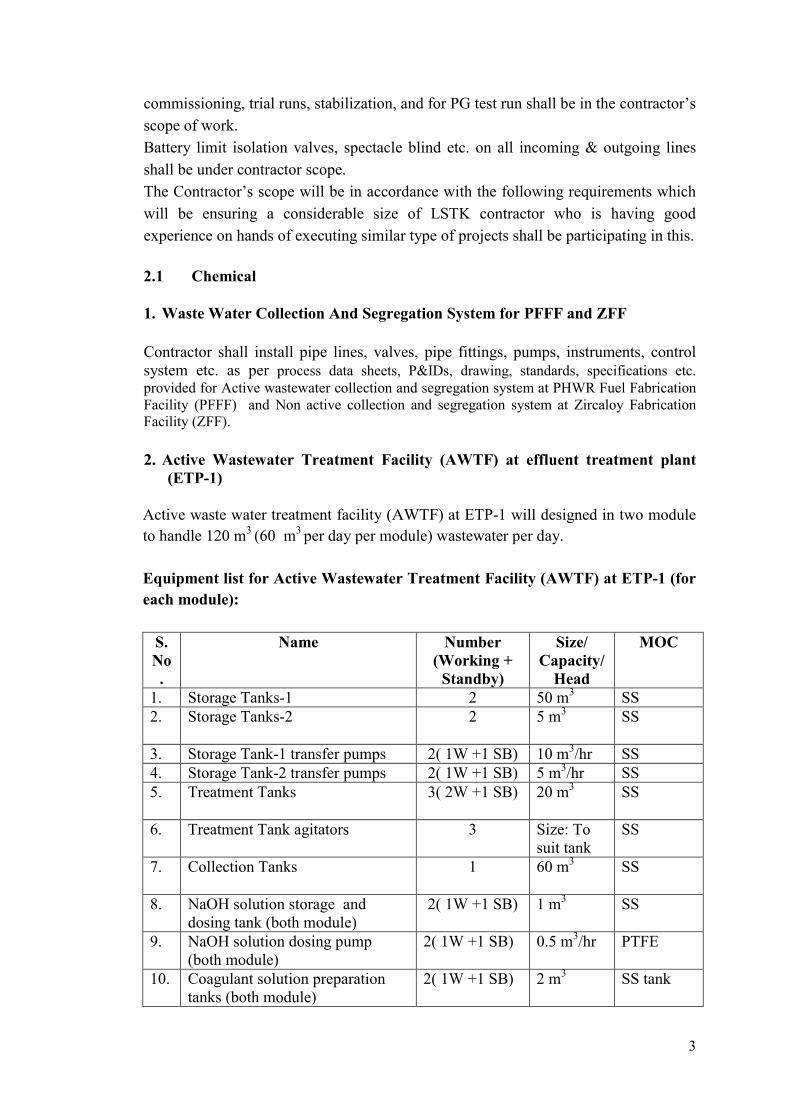
2. Active Wastewater Treatment Facility (AWTF) at effluent treatment plant (ETP-1)
Active waste water treatment facility (AWTF) at ETP-1 will designed in two module
to handle 120 m3 (60 m3 per day per module) wastewater per day.
Equipment list for Active Wastewater Treatment Facility (AWTF) at ETP-1 (for
each module):
S. No.
Name Number (Working +
Standby)
Size/ Capacity/
Head
MOC
1. Storage Tanks-1 2 50 m3 SS 2. Storage Tanks-2 2 5 m3
SS
3. Storage Tank-1 transfer pumps 2( 1W +1 SB) 10 m3/hr SS 4. Storage Tank-2 transfer pumps 2( 1W +1 SB) 5 m3/hr SS 5. Treatment Tanks 3( 2W +1 SB) 20 m3 SS
6. Treatment Tank agitators 3 Size: To
suit tank SS
7. Collection Tanks 1 60 m3
SS
8. NaOH solution storage and dosing tank (both module)
2( 1W +1 SB) 1 m3
SS
9. NaOH solution dosing pump (both module)
2( 1W +1 SB) 0.5 m3/hr PTFE
10. Coagulant solution preparation tanks (both module)
2( 1W +1 SB) 2 m3
SS tank
4
S. No.
Name Number (Working +
Standby)
Size/ Capacity/
Head
MOC
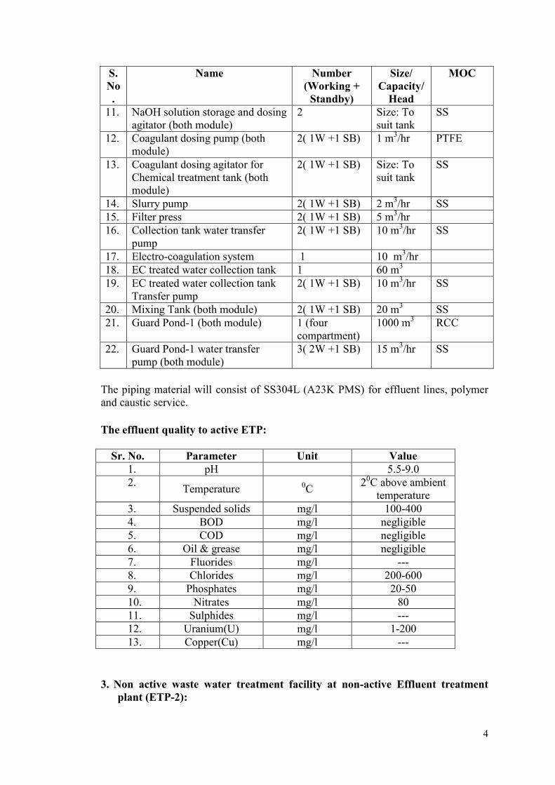
11. NaOH solution storage and dosing agitator (both module)
2 Size: To suit tank
SS
12. Coagulant dosing pump (both module)
2( 1W +1 SB) 1 m3/hr PTFE
13. Coagulant dosing agitator for Chemical treatment tank (both module)
2( 1W +1 SB) Size: To suit tank
SS
14. Slurry pump 2( 1W +1 SB) 2 m3/hr SS 15. Filter press 2( 1W +1 SB) 5 m3/hr 16. Collection tank water transfer
pump 2( 1W +1 SB) 10 m3/hr SS
17. Electro-coagulation system 1 10 m3/hr 18. EC treated water collection tank 1 60 m3 19. EC treated water collection tank
Transfer pump 2( 1W +1 SB) 10 m3/hr SS
20. Mixing Tank (both module) 2( 1W +1 SB) 20 m3 SS 21. Guard Pond-1 (both module) 1 (four
compartment) 1000 m3 RCC
22. Guard Pond-1 water transfer pump (both module)
3( 2W +1 SB) 15 m3/hr SS
The piping material will consist of SS304L (A23K PMS) for effluent lines, polymer and caustic service.
The effluent quality to active ETP:
Sr. No. Parameter Unit Value 1. pH 5.5-9.0 2.
Temperature 0C 20C above ambient
temperature 3. Suspended solids mg/l 100-400 4. BOD mg/l negligible 5. COD mg/l negligible 6. Oil & grease mg/l negligible 7. Fluorides mg/l --- 8. Chlorides mg/l 200-600 9. Phosphates mg/l 20-50 10. Nitrates mg/l 80 11. Sulphides mg/l --- 12. Uranium(U) mg/l 1-200 13. Copper(Cu) mg/l ---
3. Non active waste water treatment facility at non-active Effluent treatment plant (ETP-2):
5
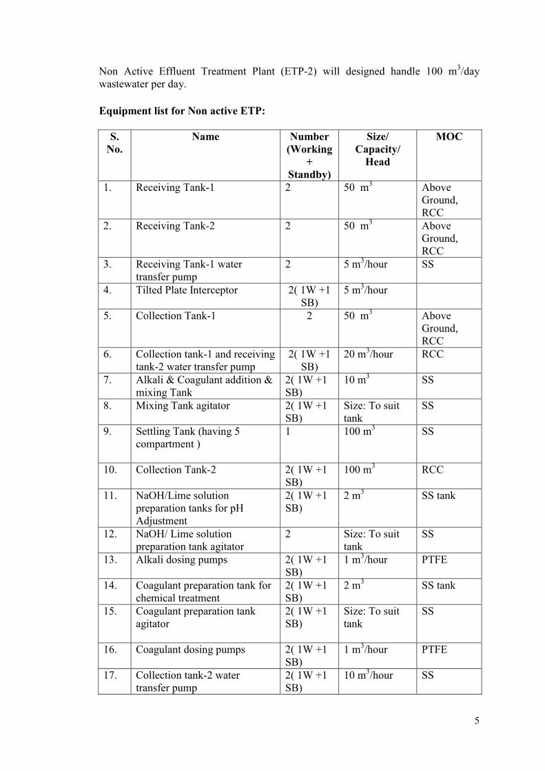
Non Active Effluent Treatment Plant (ETP-2) will designed handle 100 m3/day wastewater per day.
Equipment list for Non active ETP:
S. No.
Name Number (Working
+ Standby)
Size/ Capacity/
Head
MOC
1. Receiving Tank-1 2 50 m3 Above Ground, RCC
2. Receiving Tank-2 2 50 m3 Above Ground, RCC
3. Receiving Tank-1 water transfer pump
2 5 m3/hour SS
4. Tilted Plate Interceptor 2( 1W +1 SB)
5 m3/hour
5. Collection Tank-1 2 50 m3 Above Ground, RCC
6. Collection tank-1 and receiving tank-2 water transfer pump
2( 1W +1 SB)
20 m3/hour RCC
7. Alkali & Coagulant addition & mixing Tank
2( 1W +1 SB)
10 m3
SS
8. Mixing Tank agitator 2( 1W +1 SB)
Size: To suit tank
SS
9. Settling Tank (having 5 compartment )
1 100 m3
SS
10. Collection Tank-2 2( 1W +1 SB)
100 m3
RCC
11. NaOH/Lime solution preparation tanks for pH Adjustment
2( 1W +1 SB)
2 m3
SS tank
12. NaOH/ Lime solution preparation tank agitator
2 Size: To suit tank
SS
13. Alkali dosing pumps 2( 1W +1 SB)
1 m3/hour
PTFE
14. Coagulant preparation tank for chemical treatment
2( 1W +1 SB)
2 m3
SS tank
15. Coagulant preparation tank agitator
2( 1W +1 SB)
Size: To suit tank
SS
16. Coagulant dosing pumps 2( 1W +1 SB)
1 m3/hour
PTFE
17. Collection tank-2 water transfer pump
2( 1W +1 SB)
10 m3/hour SS
6
S. No.
Name Number (Working
+ Standby)
Size/ Capacity/
Head
MOC
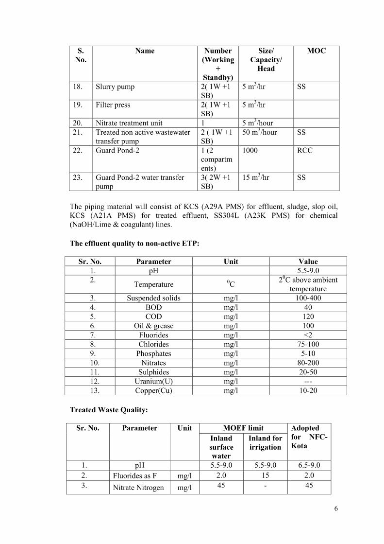
18. Slurry pump 2( 1W +1 SB)
5 m3/hr SS
19. Filter press 2( 1W +1 SB)
5 m3/hr
20. Nitrate treatment unit 1 5 m3/hour 21. Treated non active wastewater
transfer pump 2 ( 1W +1 SB)
50 m3/hour
SS
22. Guard Pond-2 1 (2 compartments)
1000 RCC
23. Guard Pond-2 water transfer pump
3( 2W +1 SB)
15 m3/hr SS
The piping material will consist of KCS (A29A PMS) for effluent, sludge, slop oil, KCS (A21A PMS) for treated effluent, SS304L (A23K PMS) for chemical (NaOH/Lime & coagulant) lines.
The effluent quality to non-active ETP:
Sr. No. Parameter Unit Value 1. pH 5.5-9.0 2.
Temperature 0C 20C above ambient
temperature 3. Suspended solids mg/l 100-400 4. BOD mg/l 40 5. COD mg/l 120 6. Oil & grease mg/l 100 7. Fluorides mg/l <2 8. Chlorides mg/l 75-100 9. Phosphates mg/l 5-10 10. Nitrates mg/l 80-200 11. Sulphides mg/l 20-50 12. Uranium(U) mg/l --- 13. Copper(Cu) mg/l 10-20
Treated Waste Quality:
Sr. No. Parameter Unit MOEF limit Adopted
for NFC-Kota
Inland surface water
Inland for irrigation
1. pH 5.5-9.0 5.5-9.0 6.5-9.0
2. Fluorides as F mg/l 2.0 15 2.0
3. Nitrate Nitrogen mg/l 45 - 45
7
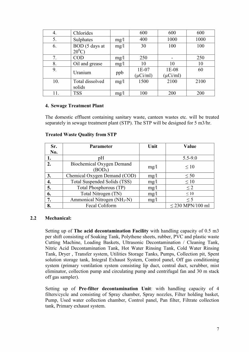
4. Chlorides 600 600 600
5. Sulphates mg/l 400 1000 1000
6. BOD (5 days at 200C)
mg/l 30 100 100
7. COD mg/l 250 - 250 8. Oil and grease mg/l 10 10 10 9.
Uranium ppb 1E-07
(µCi/ml) 1E-08
(µCi/ml) 60
10. Total dissolved solids
mg/l 1500 2100 2100
11. TSS mg/l 100 200 200
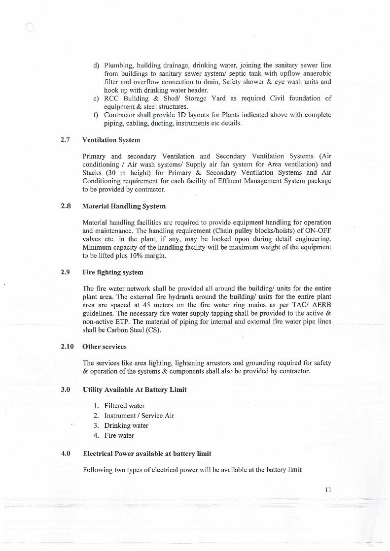
4. Sewage Treatment Plant The domestic effluent containing sanitary waste, canteen wastes etc. will be treated separately in sewage treatment plant (STP). The STP will be designed for 5 m3/hr. Treated Waste Quality from STP
Sr. No.
Parameter Unit Value
1. pH 5.5-9.0 2. Biochemical Oxygen Demand
(BOD5) mg/l ≤ 10
3. Chemical Oxygen Demand (COD) mg/l ≤ 50 4. Total Suspended Solids (TSS) mg/l ≤ 10 5. Total Phosphorous (TP) mg/l ≤ 2 6. Total Nitrogen (TN) mg/l ≤ 10
7. Ammonical Nitrogen (NH3-N) mg/l ≤ 5 8. Fecal Coliform ≤ 230 MPN/100 ml
2.2 Mechanical:
Setting up of The acid decontamination Facility with handling capacity of 0.5 m3 per shift consisting of Soaking Tank, Polythene sheets, rubber, PVC and plastic waste Cutting Machine, Loading Baskets, Ultrasonic Decontamination / Cleaning Tank, Nitric Acid Decontamination Tank, Hot Water Rinsing Tank, Cold Water Rinsing Tank, Dryer , Transfer system, Utilities Storage Tanks, Pumps, Collection pit, Spent solution storage tank, Integral Exhaust System, Control panel, Off gas conditioning system (primary ventilation system consisting lip duct, central duct, scrubber, mist eliminator, collection pump and circulating pump and centrifugal fan and 30 m stack off gas sampler).
Setting up of Pre-filter decontamination Unit: with handling capacity of 4 filters/cycle and consisting of Spray chamber, Spray nozzles, Filter holding basket, Pump, Used water collection chamber, Control panel, Pan filter, Filtrate collection tank, Primary exhaust system.
8
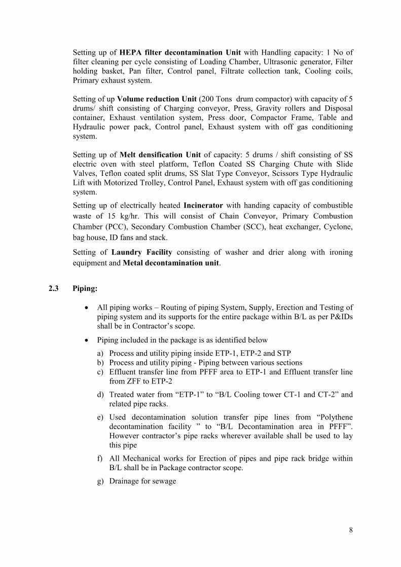
Setting up of HEPA filter decontamination Unit with Handling capacity: 1 No of filter cleaning per cycle consisting of Loading Chamber, Ultrasonic generator, Filter holding basket, Pan filter, Control panel, Filtrate collection tank, Cooling coils, Primary exhaust system. Setting of up Volume reduction Unit (200 Tons drum compactor) with capacity of 5 drums/ shift consisting of Charging conveyor, Press, Gravity rollers and Disposal container, Exhaust ventilation system, Press door, Compactor Frame, Table and Hydraulic power pack, Control panel, Exhaust system with off gas conditioning system. Setting up of Melt densification Unit of capacity: 5 drums / shift consisting of SS electric oven with steel platform, Teflon Coated SS Charging Chute with Slide Valves, Teflon coated split drums, SS Slat Type Conveyor, Scissors Type Hydraulic Lift with Motorized Trolley, Control Panel, Exhaust system with off gas conditioning system.
Setting up of electrically heated Incinerator with handing capacity of combustible
waste of 15 kg/hr. This will consist of Chain Conveyor, Primary Combustion
Chamber (PCC), Secondary Combustion Chamber (SCC), heat exchanger, Cyclone,
bag house, ID fans and stack.
Setting of Laundry Facility consisting of washer and drier along with ironing
equipment and Metal decontamination unit.
2.3 Piping:
All piping works – Routing of piping System, Supply, Erection and Testing of piping system and its supports for the entire package within B/L as per P&IDs shall be in Contractor’s scope.
Piping included in the package is as identified below
a) Process and utility piping inside ETP-1, ETP-2 and STP b) Process and utility piping - Piping between various sections c) Effluent transfer line from PFFF area to ETP-1 and Effluent transfer line
from ZFF to ETP-2
d) Treated water from “ETP-1” to “B/L Cooling tower CT-1 and CT-2” and related pipe racks.
e) Used decontamination solution transfer pipe lines from “Polythene decontamination facility ” to “B/L Decontamination area in PFFF”. However contractor’s pipe racks wherever available shall be used to lay this pipe
f) All Mechanical works for Erection of pipes and pipe rack bridge within B/L shall be in Package contractor scope.
g) Drainage for sewage
9
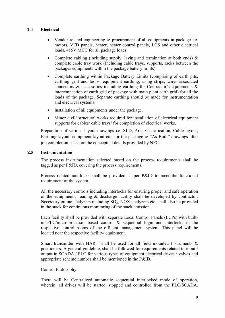
2.4 Electrical
Vendor related engineering & procurement of all equipments in package i.e. motors, VFD panels, heater, heater control panels, LCS and other electrical loads, 415V MCC for all package loads.
Complete cabling (including supply, laying and termination at both ends) & complete cable tray work (Including cable trays, supports, racks between the packages equipments within the package battery limits).
Complete earthing within Package Battery Limits (comprising of earth pits, earthing grid and loops, equipment earthing, using strips, wires associated connectors & accessories including earthing for Contractor’s equipments & interconnection of earth grid of package with main plant earth grid) for all the loads of the package. Separate earthing should be made for instrumentation and electrical systems.
Installation of all equipments under the package.
Minor civil/ structural works required for installation of electrical equipment supports for cables/ cable trays/ for completion of electrical works.
Preparation of various layout drawings i.e. SLD, Area Classification, Cable layout,
Earthing layout, equipment layout etc. for the package & “As Built” drawings after
job completion based on the conceptual details provided by NFC.
2.5 Instrumentation
The process instrumentation selected based on the process requirements shall be tagged as per P&ID, covering the process requirements. Process related interlocks shall be provided as per P&ID to meet the functional requirement of the system. All the necessary controls including interlocks for ensuring proper and safe operation of the equipments, loading & discharge facility shall be developed by contractor. Necessary online analyzers including SO2, NOX analyzers etc. shall also be provided in the stack for continuous monitoring of the stack emission. Each facility shall be provided with separate Local Control Panels (LCPs) with built-in PLC/microprocessor based control & sequential logic and interlocks in the respective control rooms of the effluent management system. This panel will be located near the respective facility/ equipment. Smart transmitter with HART shall be used for all field mounted Instruments & positioners. A general guideline, shall be followed for requirements related to input / output in SCADA / PLC for various types of equipment electrical drives / valves and appropriate scheme number shall be mentioned in the P&ID. Control Philosophy: There will be Centralized automatic sequential interlocked mode of operation, wherein, all drives will be started, stopped and controlled from the PLC/SCADA.
10
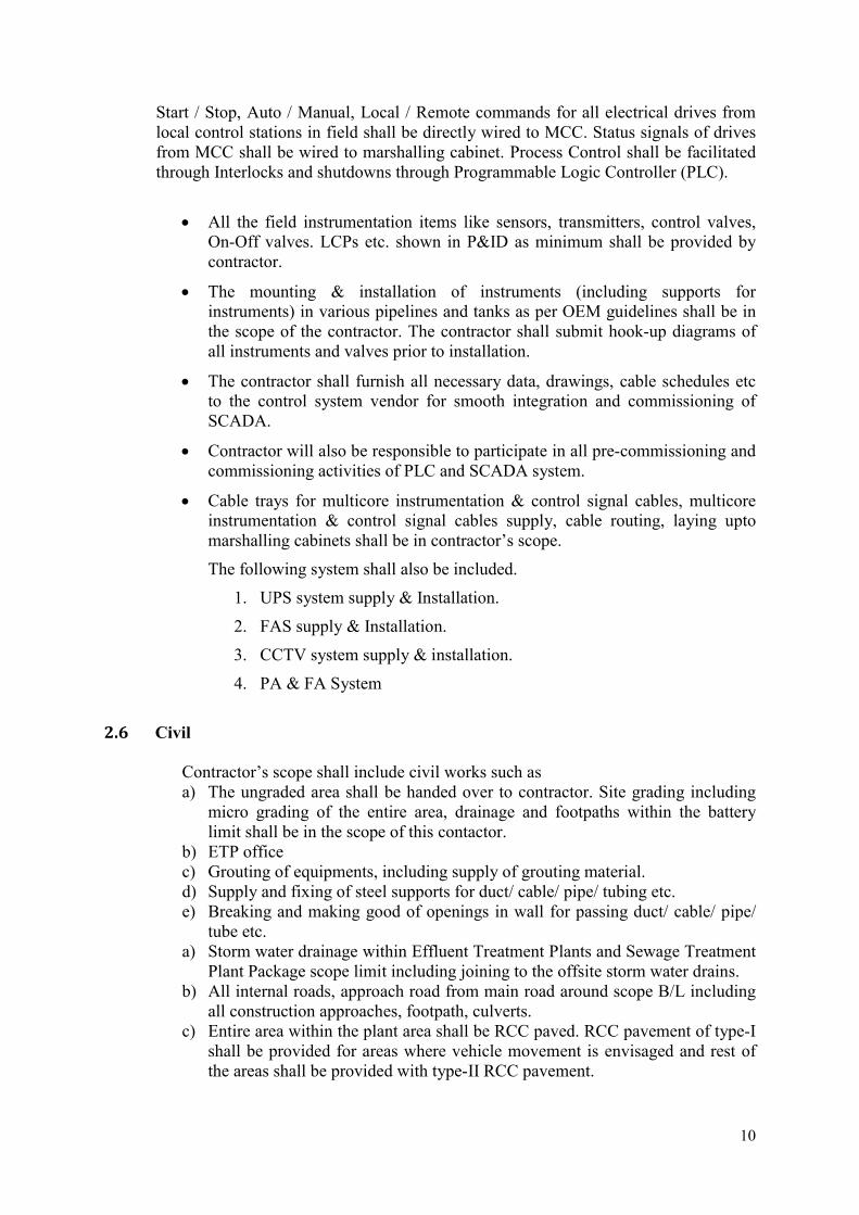
Start / Stop, Auto / Manual, Local / Remote commands for all electrical drives from local control stations in field shall be directly wired to MCC. Status signals of drives from MCC shall be wired to marshalling cabinet. Process Control shall be facilitated through Interlocks and shutdowns through Programmable Logic Controller (PLC).
All the field instrumentation items like sensors, transmitters, control valves, On-Off valves. LCPs etc. shown in P&ID as minimum shall be provided by contractor.
The mounting & installation of instruments (including supports for instruments) in various pipelines and tanks as per OEM guidelines shall be in the scope of the contractor. The contractor shall submit hook-up diagrams of all instruments and valves prior to installation.
The contractor shall furnish all necessary data, drawings, cable schedules etc to the control system vendor for smooth integration and commissioning of SCADA.
Contractor will also be responsible to participate in all pre-commissioning and commissioning activities of PLC and SCADA system.
Cable trays for multicore instrumentation & control signal cables, multicore instrumentation & control signal cables supply, cable routing, laying upto marshalling cabinets shall be in contractor’s scope.
The following system shall also be included.
1. UPS system supply & Installation.
2. FAS supply & Installation.
3. CCTV system supply & installation.
4. PA & FA System
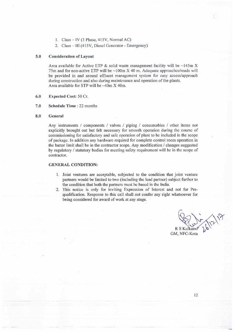
2.6 Civil
Contractor’s scope shall include civil works such as a) The ungraded area shall be handed over to contractor. Site grading including
micro grading of the entire area, drainage and footpaths within the battery limit shall be in the scope of this contactor.
b) ETP office c) Grouting of equipments, including supply of grouting material. d) Supply and fixing of steel supports for duct/ cable/ pipe/ tubing etc. e) Breaking and making good of openings in wall for passing duct/ cable/ pipe/
tube etc. a) Storm water drainage within Effluent Treatment Plants and Sewage Treatment
Plant Package scope limit including joining to the offsite storm water drains. b) All internal roads, approach road from main road around scope B/L including
all construction approaches, footpath, culverts. c) Entire area within the plant area shall be RCC paved. RCC pavement of type-I
shall be provided for areas where vehicle movement is envisaged and rest of the areas shall be provided with type-II RCC pavement.
13
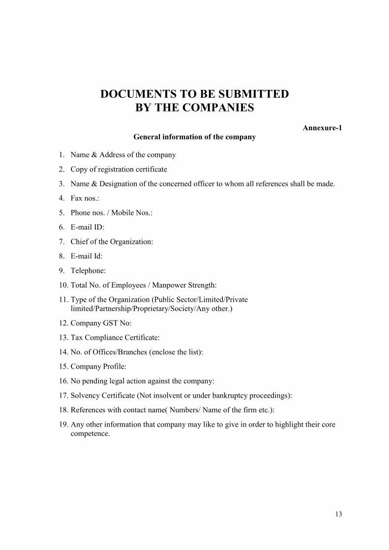
DOCUMENTS TO BE SUBMITTED BY THE COMPANIES
Annexure-1
General information of the company
1. Name & Address of the company
2. Copy of registration certificate
3. Name & Designation of the concerned officer to whom all references shall be made.
4. Fax nos.:
5. Phone nos. / Mobile Nos.:
6. E-mail ID:
7. Chief of the Organization:
8. E-mail Id:
9. Telephone:
10. Total No. of Employees / Manpower Strength:
11. Type of the Organization (Public Sector/Limited/Private limited/Partnership/Proprietary/Society/Any other.)
12. Company GST No:
13. Tax Compliance Certificate:
14. No. of Offices/Branches (enclose the list):
15. Company Profile:
16. No pending legal action against the company:
17. Solvency Certificate (Not insolvent or under bankruptcy proceedings):
18. References with contact name( Numbers/ Name of the firm etc.):
19. Any other information that company may like to give in order to highlight their core competence.
14
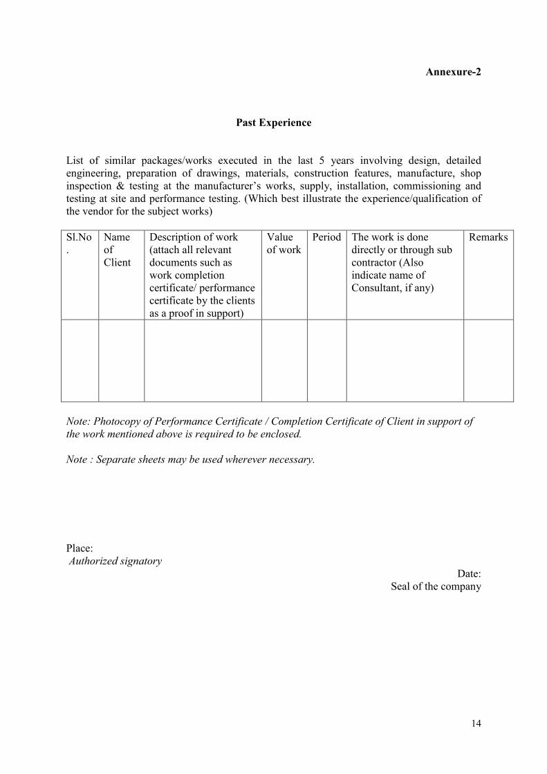
Annexure-2
Past Experience List of similar packages/works executed in the last 5 years involving design, detailed engineering, preparation of drawings, materials, construction features, manufacture, shop inspection & testing at the manufacturer’s works, supply, installation, commissioning and testing at site and performance testing. (Which best illustrate the experience/qualification of the vendor for the subject works) Sl.No.
Name of Client
Description of work (attach all relevant documents such as work completion certificate/ performance certificate by the clients as a proof in support)
Value of work
Period The work is done directly or through sub contractor (Also indicate name of Consultant, if any)
Remarks
Note: Photocopy of Performance Certificate / Completion Certificate of Client in support of the work mentioned above is required to be enclosed. Note : Separate sheets may be used wherever necessary. Place: Authorized signatory
Date: Seal of the company
15
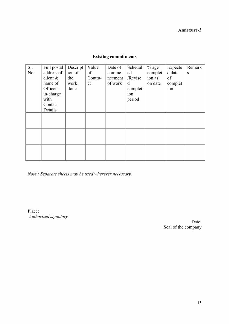
Annexure-3
Existing commitments
Sl. No.
Full postal address of client & name of Officer-in-charge with Contact Details
Description of the work done
Value of Contra-ct
Date of commencement of work
Scheduled /Revised completion period
% age completion as on date
Expected date of completion
Remarks
Note : Separate sheets may be used wherever necessary. Place: Authorized signatory
Date: Seal of the company
16
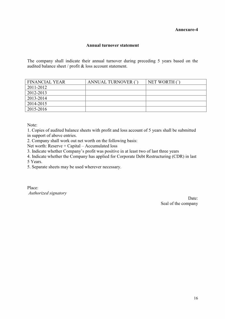
Annexure-4
Annual turnover statement
The company shall indicate their annual turnover during preceding 5 years based on the audited balance sheet / profit & loss account statement. FINANCIAL YEAR ANNUAL TURNOVER (`) NET WORTH (`) 2011-2012 2012-2013 2013-2014 2014-2015 2015-2016 Note: 1. Copies of audited balance sheets with profit and loss account of 5 years shall be submitted in support of above entries. 2. Company shall work out net worth on the following basis: Net worth: Reserve + Capital – Accumulated loss 3. Indicate whether Company’s profit was positive in at least two of last three years 4. Indicate whether the Company has applied for Corporate Debt Restructuring (CDR) in last 5 Years. 5. Separate sheets may be used wherever necessary. Place: Authorized signatory
Date: Seal of the company
17
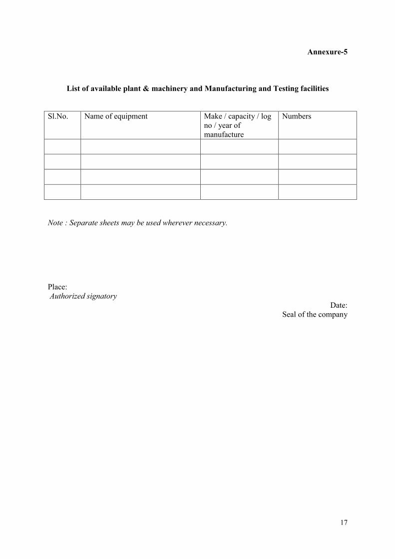
Annexure-5
List of available plant & machinery and Manufacturing and Testing facilities
Sl.No. Name of equipment Make / capacity / log no / year of manufacture
Numbers
Note : Separate sheets may be used wherever necessary. Place: Authorized signatory
Date: Seal of the company