Embed Size (px)
Citation preview
208
Bulgarian Chemical Communications, Volume 48, Special Issue G (pp. 208-212) 2016
Bright green phosphorescent organic light-emitting diode with doped hole
transporting layer
P. Ivanov*, P. Petrova, R. Tomova
Institute of Optical Materials and Technolologies “Acad. J. Malinowski”,
Bulgarian Academy of Sciences, Acad. G. Bonchev str. bl. 109, 1113 Sofia,Bulgaria
Received October 10, 2016; Revised November 20, 2016
The application of green phosphorescent complex Tris[2-phenylpyridinato-C2,N]iridium(III) - Ir(ppy)3 as a dopant in
the hole transporting layer (HTL) of Organic light emitting diode (OLED) structure: HTL/ElL/ETL has been studied.
We have found that devices containing from 4 wt.% - 6 wt.% Ir(ppy)3 emit pure green light with
CIE (x;y) chromaticity coordinates 0.2969; 0.4860 - 0.3184; 04905 very close to these of the ideal green color 0.3; 0.6,
which is recommended at the displays manufacturing.
Keywords: Phosphorescent OLED, Cyclometalated iridium complexes, Tris[2-phenylpyridinato-C2,N]iridium(III)
(Ir(ppy)3)
INTRODUCTION
Since Baldo et al. reported the first example of
electrophosphorescence at room temperature,
phosphorescent materials have attracted much
attention due to their high external quantum
efficiencies in organic light emitting diodes
(OLEDs) [1, 2]. Extensive investigations of
phosphorescent materials have focused on d6 and d8
heavy metal complexes such as Os(ІІ) [3], Ir(ІІІ) [4,
5] and Pt(ІІ) [6]. OLEDs based on those
phosphorescent materials can significantly improve
electroluminescent performances because both
singlet and triplet excitons can be harvested for
light emission by strong spin-orbit coupling. The
internal quantum efficiency of phosphorescent
emitters can theoretically approach 100%, and the
external quantum efficiency can approach 20% [7,
8, 9]. Due to their strong spin-orbit coupling, these
complexes can burrow intensity from the singlet
metal-to-ligand-charge-transfer (1MLCT) state and
emit effectively from their triplet 3MLCT states.
Among all phosphorescent complexes these based
on iridium recently are the subject of intensive
studying, because Ir atom owns intense
phosphorescence at room temperature, stable and
accessible oxidation and reduction states and quasi-
octahedral geometry, permitting introducing of
specific ligands in a controlled manner [1, 10, 11].
Tris[2-phenylpyridinato-C2,N]iridium(III)
(Ir(ppy)3) is one of the most important materials for
phosphorescent OLED as its emission color at λmax
= 514 nm matches well to the Commission
Internationale d’Eclairage coordinates (CIE(x/y))
for green color (0.3;0.6), that makes it very suitable
for use in the production of full color displays [12-
15]. The high efficiency devices with Ir(ppy)3
doped with electroluminescent layer is based on (i)
the high cross-section for formation of electron-
hole pairs (singlet and triplet excitons) on Ir(ppy)3
in matrix materials, (ii) a fast intersystem crossing
from the excited singlet to the emitting triplet
states, and (iii) on the high emission quantum yield
of about 40% of the triplet sub-states at ambient
temperature [11]. Usually as a host matrix for
Ir(ppy)3 guest are preferred materials with wide
band gap: small molecule compounds as 4,4′-N,N′-
Dicarbazolylbiphenyl (CBP) [16-19]; 4,4',4"-tri(N-
carbazolyl) triphenylamine (TCTA) [20]used in
multilayered OLEDs obtained by thermal
evaporation, and Poly(9-vinylcarbazole) (PVK) in
monolayer electrophosphorescent polymer light-
emitting diodes (PLED) produced by spin coating
or spin casting. PVK is one of the widely used
polymers because in addition to its large HOMO–
LUMO separation, owns relatively high value of
the lowest triplet state T1 (about 2.5 eV) preventing
back crossing of the triplet exciton from the
phosphor to the host triplet state [21-23]. The main
advantage of using a polymer matrix as a host
material in comparison with such based on small
molecule compound is the easy manner of control * To whom all correspondence should be sent:
E-mail: [email protected]
Ivanov et al.: Bright green Phosphorescent Organic Light-Emitting Diode …
209
of the dopant concentration. That is why, in recent
years high-performance devices fabricated by
employing Ir(ppy)3 incorporated in conjugated and
non-conjugated polymer hosts were reported [12,
24] although PLEDs are less efficient than small
molecule type devices. In this paper we present the results obtained for
OLED structure with Ir(ppy)3 doped composite hole
transporting layer (HTL) of PVK:TPD in effort to
obtain appropriate for display application device
emitting pure and stable green light with CIE
coordinates close to these of the ideal green color
(0.3;0.6).
EXPERIMENTAL
OLED fabrication
We investigated the multilayered OLED
structure of ITO/doped-HTL/ElL/ETL/M, where
ITO was a transparent anode of In2O3:SnO2, M - a
metallic Al cathode, HTL -N,N′-Bis(3-
methylphenyl)-N,N′-diphenylbenzidine (TPD)
involved in poly(N-vinylcarbazole) (PVK) matrix,
ElL - electroluminescent layer of Bis(8-hydroxy-2-
methylquinoline)-(4-phenylphenoxy)aluminum
(BAlq) and ETL - electron-transporting layer of
Bis[2-(2-benzothiazoly)phenolato]zinc (Zn(bt)2).
Devices with area of 1cm2 were prepared on
commercial polyethylene terephtalate (PET)
substrates coated with ITO (40 Ω/sq). The layer (30
nm) of PVK:TPD (10%(relatively to PVK) +
Ir(ppy)3 composite films were prepared by spin-
coating from 0.75% PVK solution in
dichloroethane at 2000 rpm. Other organic layers
BAlq (40nm) and Zn(bt)2 (35nm), and the Al
cathode (100nm) were deposited by thermal
evaporation in vacuum better than 10-4 Pa at rates
2-5 Ǻ/s, without interrupting the vacuum. The
layers thicknesses were controlled in situ with
quartz crystal microbalance sensor, positioned near
the PET/ITO substrate.
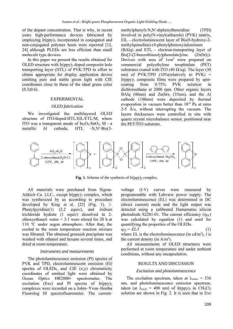
Fig. 1. Scheme of the synthesis of Ir(ppy)3 complex.
All materials were purchased from Sigma-
Aldrich Co. LLC., except Ir(ppy)3 complex, which
was synthesized by us according to procedure
developed by King et al. [25] (Fig. 1). 2-
Phenylpyridine(1) (2.2 equiv), and iridium
trichloride hydrate (1 equiv) dissolved in 2-
ethoxyethanol: water = 3:1 were stirred for 20 h at
110 oC under argon atmosphere. After that, the
cooled to the room temperature reaction mixture
was filtrated. The obtained greenish precipitate was
washed with ethanol and hexane several times, and
dried at room temperature.
Instruments and measurements
The photoluminescence emission (Pl) spectra of
PVK and TPD, electroluminescent emission (El)
spectra of OLEDs, and CIE (x;y) chromaticity
coordinates of emitted light were obtained by
Ocean Optics HR2000+ spectrometer. The
excitation (Exc) and Pl spectra of Ir(ppy)3
complexes were recorded on a Jobin–Yvon–Horiba
Fluorolog III spectrofluorometer. The current-
voltage (I-V) curves were measured by
programmable with Labview power supply. The
electroluminescence (EL) was determined in DC
(direct current) mode and the light output was
detected using a calibrated Hamamatsu silicon
photodiode S2281-01. The current efficiency (ηEL)
was calculated by equation (1) and used for
quantifying the properties of the OLEDs.
ηEL = EL/I (1)
where EL is the electroluminescence (in cd/m2), I is
the current density (in A/m2). All measurements of OLED structures were
performed at room temperature and under ambient
conditions, without any encapsulation.
RESULTS AND DISCUSSION
Excitation and photoluminescence
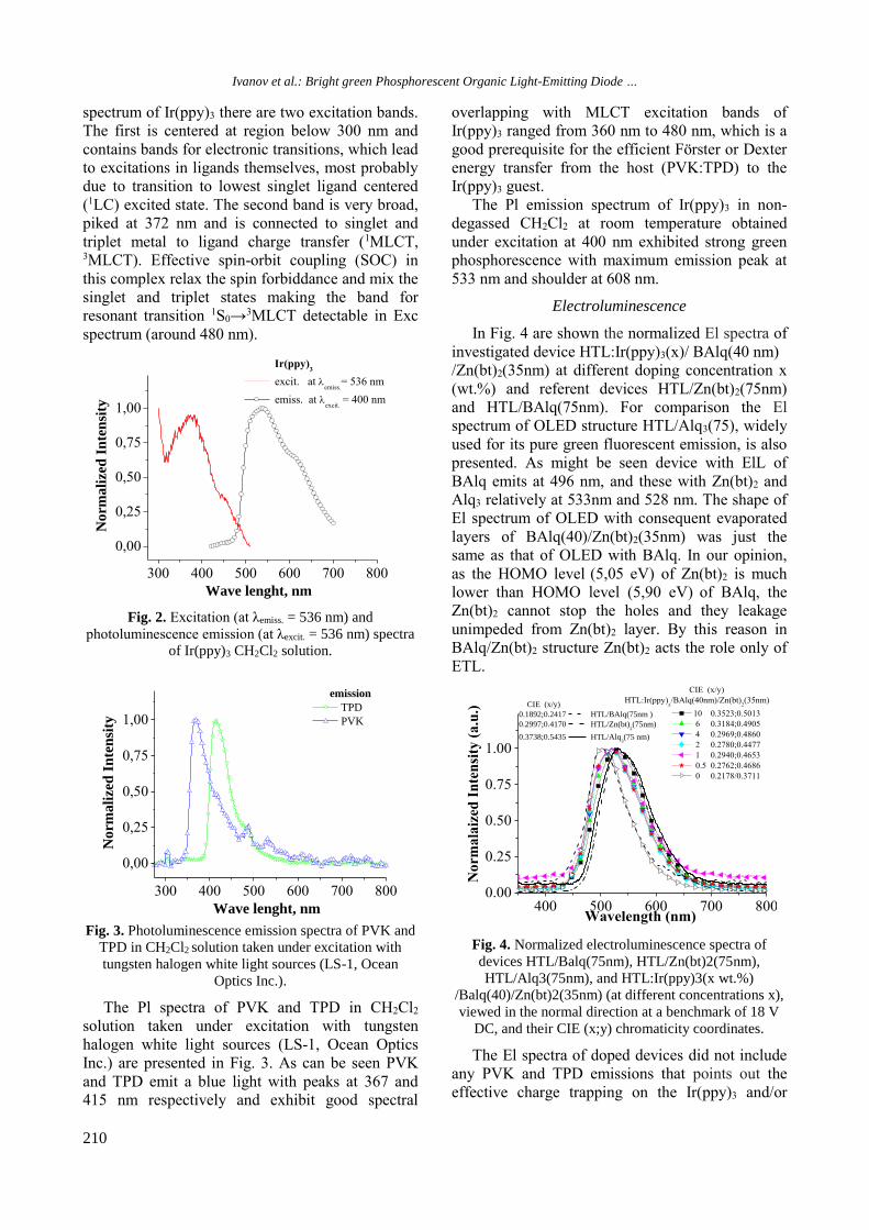
The excitation spectrum, taken at λemiss = 536
nm, and photoluminescence emission spectrum,
taken (at λexcit = 400 nm) of Ir(ppy)3 in CH2Cl2
solution are shown in Fig. 2. It is seen that in Exc
Ivanov et al.: Bright green Phosphorescent Organic Light-Emitting Diode …
210
spectrum of Ir(ppy)3 there are two excitation bands.
The first is centered at region below 300 nm and
contains bands for electronic transitions, which lead
to excitations in ligands themselves, most probably
due to transition to lowest singlet ligand centered
(1LC) excited state. The second band is very broad,
piked at 372 nm and is connected to singlet and
triplet metal to ligand charge transfer (1MLCT, 3MLCT). Effective spin-orbit coupling (SOC) in
this complex relax the spin forbiddance and mix the
singlet and triplet states making the band for
resonant transition 1S0→3MLCT detectable in Exc
spectrum (around 480 nm).
Fig. 2. Excitation (at λemiss. = 536 nm) and
photoluminescence emission (at λexcit. = 536 nm) spectra
of Ir(ppy)3 CH2Cl2 solution.
Fig. 3. Photoluminescence emission spectra of PVK and
TPD in CH2Cl2 solution taken under excitation with
tungsten halogen white light sources (LS-1, Ocean
Optics Inc.).
The Pl spectra of PVK and TPD in CH2Cl2
solution taken under excitation with tungsten
halogen white light sources (LS-1, Ocean Optics
Inc.) are presented in Fig. 3. As can be seen PVK
and TPD emit a blue light with peaks at 367 and
415 nm respectively and exhibit good spectral
overlapping with MLCT excitation bands of
Ir(ppy)3 ranged from 360 nm to 480 nm, which is a
good prerequisite for the efficient Förster or Dexter
energy transfer from the host (PVK:TPD) to the
Ir(ppy)3 guest.
The Pl emission spectrum of Ir(ppy)3 in non-
degassed CH2Cl2 at room temperature obtained
under excitation at 400 nm exhibited strong green
phosphorescence with maximum emission peak at
533 nm and shoulder at 608 nm.
Electroluminescence
In Fig. 4 are shown the normalized El spectra of
investigated device HTL:Ir(ppy)3(x)/ BAlq(40 nm)
/Zn(bt)2(35nm) at different doping concentration x
(wt.%) and referent devices HTL/Zn(bt)2(75nm)
and HTL/BAlq(75nm). For comparison the El
spectrum of OLED structure HTL/Alq3(75), widely
used for its pure green fluorescent emission, is also
presented. As might be seen device with ElL of
BAlq emits at 496 nm, and these with Zn(bt)2 and
Alq3 relatively at 533nm and 528 nm. The shape of
El spectrum of OLED with consequent evaporated
layers of BAlq(40)/Zn(bt)2(35nm) was just the
same as that of OLED with BAlq. In our opinion,
as the HOMO level (5,05 eV) of Zn(bt)2 is much
lower than HOMO level (5,90 eV) of BAlq, the
Zn(bt)2 cannot stop the holes and they leakage
unimpeded from Zn(bt)2 layer. By this reason in
BAlq/Zn(bt)2 structure Zn(bt)2 acts the role only of
ETL.
Fig. 4. Normalized electroluminescence spectra of
devices HTL/Balq(75nm), HTL/Zn(bt)2(75nm),
HTL/Alq3(75nm), and HTL:Ir(ppy)3(x wt.%)
/Balq(40)/Zn(bt)2(35nm) (at different concentrations x),
viewed in the normal direction at a benchmark of 18 V
DC, and their CIE (x;y) chromaticity coordinates.
The El spectra of doped devices did not include
any PVK and TPD emissions that points out the
effective charge trapping on the Ir(ppy)3 and/or
300 400 500 600 700 800
0,00
0,25
0,50
0,75
1,00
No
rmali
zed
In
ten
sity
Wave lenght, nm
Ir(ppy)3
excit. at emiss.
= 536 nm
emiss. at excit.
= 400 nm
300 400 500 600 700 800
0,00
0,25
0,50
0,75
1,00
emission
TPD
PVK
No
rmali
zed
In
ten
sity
Wave lenght, nm 400 500 600 700 8000.00
0.25
0.50
0.75
1.00
CIE (x/y)
0.1892;0.2417 HTL/BAlq(75nm )
0.2997;0.4170 HTL/Zn(bt)2(75nm)
0.3738;0.5435 HTL/Alq3(75 nm)
CIE (x/y)
HTL:Ir(ppy)x/BAlq(40nm)/Zn(bt)
2(35nm)
10 0.3523;0.5013
6 0.3184;0.4905
4 0.2969;0.4860
2 0.2780;0.4477
1 0.2940;0.4653
0.5 0.2762;0.4686
0 0.2178/0.3711
No
rma
laiz
ed I
nte
nsi
ty (
a.u
.)
Wavelength (nm)
Ivanov et al.: Bright green Phosphorescent Organic Light-Emitting Diode …
211
effective energy transfer from host to the complex
guest. The increasing of the dopant concentration x
caused a decreasing of the relative intensity of the
bluish-green emission of BAlq at 496 nm, and red
shifting of λmax and CIE (x;y) coordinates from 504
nm and 0,2178;0, 3711 (bluish-green) for undoped
device to 525 nm and 0,3523; 0,5013 (greenish-
yellow) for device doped with 10 wt.% of Ir(ppy)3.
Devices doped with 4 wt.%≤ x ≤ 6 wt.%
demonstrated CIE (x;y) coordinates in the range
from 0.2969; 0.4860 to 0.3184; 04905 which were a
lot closer to these of the ideal green color 0.3; 0.6 in
comparison with these (0.3738; 0.5435) displayed
by OLED with ElL of Alq3.
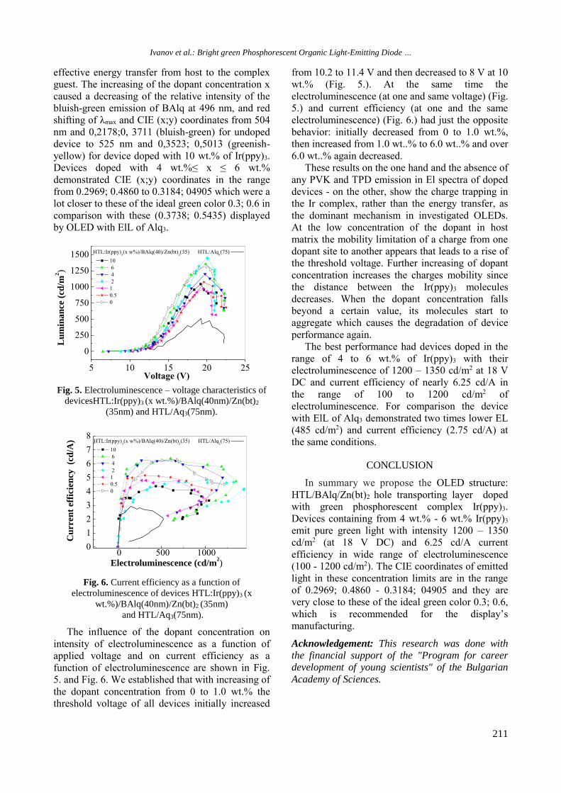
Fig. 5. Electroluminescence – voltage characteristics of
devicesHTL:Ir(ppy)3 (x wt.%)/BAlq(40nm)/Zn(bt)2
(35nm) and HTL/Aq3(75nm).
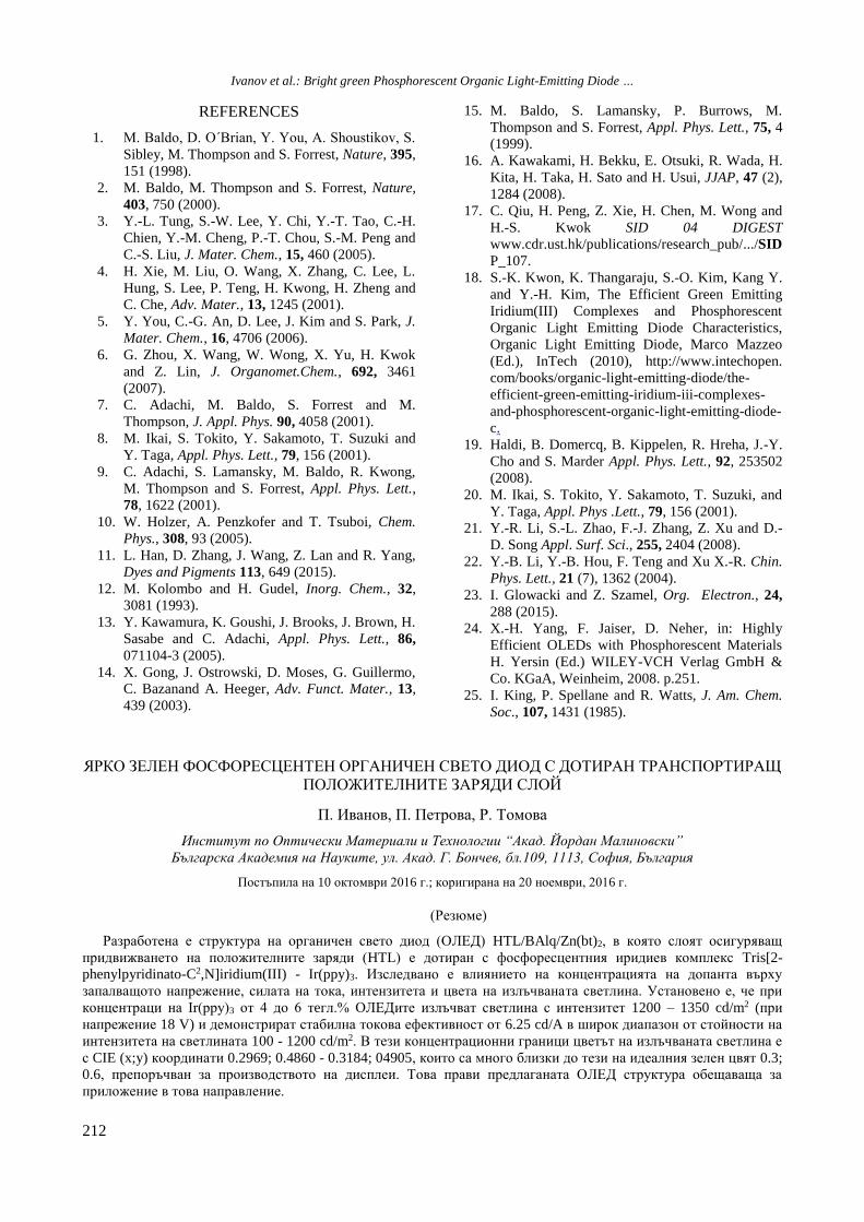
Fig. 6. Current efficiency as a function of
electroluminescence of devices HTL:Ir(ppy)3 (x
wt.%)/BAlq(40nm)/Zn(bt)2 (35nm)
and HTL/Aq3(75nm).
The influence of the dopant concentration on
intensity of electroluminescence as a function of
applied voltage and on current efficiency as a
function of electroluminescence are shown in Fig.
5. and Fig. 6. We established that with increasing of
the dopant concentration from 0 to 1.0 wt.% the
threshold voltage of all devices initially increased
from 10.2 to 11.4 V and then decreased to 8 V at 10
wt.% (Fig. 5.). At the same time the
electroluminescence (at one and same voltage) (Fig.
5.) and current efficiency (at one and the same
electroluminescence) (Fig. 6.) had just the opposite
behavior: initially decreased from 0 to 1.0 wt.%,
then increased from 1.0 wt..% to 6.0 wt..% and over
6.0 wt..% again decreased.
These results on the one hand and the absence of
any PVK and TPD emission in El spectra of doped
devices - on the other, show the charge trapping in
the Ir complex, rather than the energy transfer, as
the dominant mechanism in investigated OLEDs.
At the low concentration of the dopant in host
matrix the mobility limitation of a charge from one
dopant site to another appears that leads to a rise of
the threshold voltage. Further increasing of dopant
concentration increases the charges mobility since
the distance between the Ir(ppy)3 molecules
decreases. When the dopant concentration falls
beyond a certain value, its molecules start to
aggregate which causes the degradation of device
performance again.
The best performance had devices doped in the
range of 4 to 6 wt.% of Ir(ppy)3 with their
electroluminescence of 1200 – 1350 cd/m2 at 18 V
DC and current efficiency of nearly 6.25 cd/A in
the range of 100 to 1200 cd/m2 of
electroluminescence. For comparison the device
with ElL of Alq3 demonstrated two times lower EL
(485 cd/m2) and current efficiency (2.75 cd/A) at
the same conditions.
CONCLUSION
In summary we propose the OLED structure:
HTL/BAlq/Zn(bt)2 hole transporting layer doped
with green phosphorescent complex Ir(ppy)3.
Devices containing from 4 wt.% - 6 wt.% Ir(ppy)3
emit pure green light with intensity 1200 – 1350
cd/m2 (at 18 V DC) and 6.25 cd/A current
efficiency in wide range of electroluminescence
(100 - 1200 cd/m2). The CIE coordinates of emitted
light in these concentration limits are in the range
of 0.2969; 0.4860 - 0.3184; 04905 and they are
very close to these of the ideal green color 0.3; 0.6,
which is recommended for the display’s
manufacturing.
Acknowledgement: This research was done with
the financial support of the "Program for career
development of young scientists" of the Bulgarian
Academy of Sciences.
5 10 15 20 25
0
250
500
750
1000
1250
1500 HTL:Ir(ppy)3(x w%)/BAlq(40)/Zn(bt)
2(35) HTL/Alq
3(75)
10
6
4
2
1
0.5
0
Voltage (V)
Lu
min
an
ce (
cd/m
2)
0 500 10000
1
2
3
4
5
6
7
8HTL:Ir(ppy)
3(x w%)/BAlq(40)/Zn(bt)
2(35) HTL/Alq
3(75)
10
6
4
2
1
0.5
0
Electroluminescence (cd/m2)
Cu
rren
t ef
fici
ency
(c
d/A
)
Ivanov et al.: Bright green Phosphorescent Organic Light-Emitting Diode …
212
REFERENCES
1. M. Baldo, D. O΄Brian, Y. You, A. Shoustikov, S.
Sibley, M. Thompson and S. Forrest, Nature, 395,
151 (1998).
2. M. Baldo, M. Thompson and S. Forrest, Nature,
403, 750 (2000).
3. Y.-L. Tung, S.-W. Lee, Y. Chi, Y.-T. Tao, C.-H.
Chien, Y.-M. Cheng, P.-T. Chou, S.-M. Peng and
C.-S. Liu, J. Mater. Chem., 15, 460 (2005).
4. H. Xie, M. Liu, O. Wang, X. Zhang, C. Lee, L.
Hung, S. Lee, P. Teng, H. Kwong, H. Zheng and
C. Che, Adv. Mater., 13, 1245 (2001).
5. Y. You, C.-G. An, D. Lee, J. Kim and S. Park, J.
Mater. Chem., 16, 4706 (2006).
6. G. Zhou, X. Wang, W. Wong, X. Yu, H. Kwok
and Z. Lin, J. Organomet.Chem., 692, 3461
(2007).
7. C. Adachi, M. Baldo, S. Forrest and M.
Thompson, J. Appl. Phys. 90, 4058 (2001).
8. M. Ikai, S. Tokito, Y. Sakamoto, T. Suzuki and
Y. Taga, Appl. Phys. Lett., 79, 156 (2001).
9. C. Adachi, S. Lamansky, M. Baldo, R. Kwong,
M. Thompson and S. Forrest, Appl. Phys. Lett.,
78, 1622 (2001).
10. W. Holzer, A. Penzkofer and T. Tsuboi, Chem.
Phys., 308, 93 (2005).
11. L. Han, D. Zhang, J. Wang, Z. Lan and R. Yang,
Dyes and Pigments 113, 649 (2015).
12. M. Kolombo and H. Gudel, Inorg. Chem., 32,
3081 (1993).
13. Y. Kawamura, K. Goushi, J. Brooks, J. Brown, H.
Sasabe and C. Adachi, Appl. Phys. Lett., 86,
071104-3 (2005).
14. X. Gong, J. Ostrowski, D. Moses, G. Guillermo,
C. Bazanand A. Heeger, Adv. Funct. Mater., 13,
439 (2003).
15. M. Baldo, S. Lamansky, P. Burrows, M.
Thompson and S. Forrest, Appl. Phys. Lett., 75, 4
(1999).
16. A. Kawakami, H. Bekku, E. Otsuki, R. Wada, H.
Kita, H. Taka, H. Sato and H. Usui, JJAP, 47 (2),
1284 (2008).
17. C. Qiu, H. Peng, Z. Xie, H. Chen, M. Wong and
H.-S. Kwok SID 04 DIGEST
www.cdr.ust.hk/publications/research_pub/.../SID
P_107.
18. S.-K. Kwon, K. Thangaraju, S.-O. Kim, Kang Y.
and Y.-H. Kim, The Efficient Green Emitting
Iridium(III) Complexes and Phosphorescent
Organic Light Emitting Diode Characteristics,
Organic Light Emitting Diode, Marco Mazzeo
(Ed.), InTech (2010), http://www.intechopen.
com/books/organic-light-emitting-diode/the-
efficient-green-emitting-iridium-iii-complexes-
and-phosphorescent-organic-light-emitting-diode-
c.
19. Haldi, B. Domercq, B. Kippelen, R. Hreha, J.-Y.
Cho and S. Marder Appl. Phys. Lett., 92, 253502
(2008).
20. M. Ikai, S. Tokito, Y. Sakamoto, T. Suzuki, and
Y. Taga, Appl. Phys .Lett., 79, 156 (2001).
21. Y.-R. Li, S.-L. Zhao, F.-J. Zhang, Z. Xu and D.-
D. Song Appl. Surf. Sci., 255, 2404 (2008).
22. Y.-B. Li, Y.-B. Hou, F. Teng and Xu X.-R. Chin.
Phys. Lett., 21 (7), 1362 (2004).
23. I. Glowacki and Z. Szamel, Org. Electron., 24,
288 (2015).
24. X.-H. Yang, F. Jaiser, D. Neher, in: Highly
Efficient OLEDs with Phosphorescent Materials
H. Yersin (Ed.) WILEY-VCH Verlag GmbH &
Co. KGaA, Weinheim, 2008. p.251.
25. I. King, P. Spellane and R. Watts, J. Am. Chem.
Soc., 107, 1431 (1985).
ЯРКО ЗЕЛЕН ФОСФОРЕСЦЕНТЕН ОРГАНИЧЕН СВЕТО ДИОД С ДОТИРАН ТРАНСПОРТИРАЩ
ПОЛОЖИТEЛНИТЕ ЗАРЯДИ СЛОЙ
П. Иванов, П. Петрова, Р. Томова
Институт по Оптически Материали и Технологии “Акад. Йордан Малиновски”
Българска Академия на Науките, ул. Акад. Г. Бончев, бл.109, 1113, София, България
Постъпила на 10 октомври 2016 г.; коригирана на 20 ноември, 2016 г.
(Резюме)
Разработена е структура на органичен свето диод (ОЛЕД) HTL/BAlq/Zn(bt)2, в която слоят осигуряващ
придвижването на положителните заряди (HTL) е дотиран с фосфоресцентния иридиев комплекс Tris[2-
phenylpyridinato-C2,N]iridium(III) - Ir(ppy)3. Изследвано е влиянието на концентрацията на допанта върху
запалващото напрежение, силата на тока, интензитета и цвета на излъчваната светлина. Установено е, че при
концентраци на Ir(ppy)3 от 4 до 6 тeгл.% ОЛЕДите излъчват светлина с интензитет 1200 – 1350 cd/m2 (при
напрежение 18 V) и демонстрират стабилна токова ефективност от 6.25 cd/A в широк диапазон от стойности на
интензитета на светлината 100 - 1200 cd/m2. В тези концентрационни граници цветът на излъчваната светлина е
с CIE (x;y) координати 0.2969; 0.4860 - 0.3184; 04905, които са много близки до тези на идеалния зелен цвят 0.3;
0.6, препоръчван за производството на дисплеи. Това прави предлаганата ОЛЕД структура обещаваща за
приложение в това направление.