Embed Size (px)
Citation preview
Analyze Tool Wear of Cemented Tungsten Carbide End Mill 2T, 3T, 4T
for Output of Force and Temperature Data using Third Wave
AdvantEdge Software Simulation
SCIENTIFIC PUBLICATION
Arranged as a requirement to complete Undergraduate Study Program in
Mechanical Engineering, Engineering Faculty
By:
BRILIAN REXA BUANA D200133008
MECHANICAL ENGINEERING DEPARTMENT
ENGINEERING FACULTY
UNIVERSITAS MUHAMMADIYAH SURAKARTA
2017
APPROVAL SHEET
i
APPROVAL SHEET
ii

iii
1
Analyze Tool Wear of Cemented Tungsten Carbide End Mill 2T,
3T, 4T for Output of Force and Temperature Data using Third
Wave AdvantEdge Software Simulation
1Brilian Rexa Buana, 2Wijianto, 3Feng Qing
1Bachelor Student, Dept. of Mechanical Engineering, Wuxi Institute of Technology,
China, 2Mechanical Engineering Universitas Muhammadiyah Surakarta, 3Mechanical
Engineering Wuxi Institute of Technology. [email protected]
ABSTRACT
Tool wear is one of the most important topic in cutting field. Its interest is
due to the influence of tool wear on surface integrity of the final parts and on tool
life, and, consequently, on the substitution policies and production costs. The
methods of process of cutting tool design has been massively used in industrial
world. Based on the seeking the best performance needs of production, it is crucial
to set up the proper cutters. Variations of cutting tool of 2 flute and 3 flute End
Mill Cemented Tungsten Carbide Material with serial type of YT15(P10) by
diameter 6mm, 8mm, 10mm, respectively are tested using FEM method using
simulation of Finite Element Analysis Software which is Third Wave AdvantEdge
to predict the cutting force, temperature tested on Stainless Steel AISI 1045. It also
accumulated with 4 flute End Mill. Comparing those for seeking the best performance production and machining parameters by manufacturing process
Keausan alat adalah salah satu topik yang paling penting dalam bidang
pemotongan. Hal tersebut terjadi karena pengaruh keausan alat pada integritas
permukaan bagian akhir dan pada umur alat, dan akibatnya, pada kebijakan
substitusi dan biaya produksi. Metode proses perancangan alat potong telah
banyak digunakan di dunia industri. Berdasarkan pada mencari kebutuhan
produksi terbaik, sangat penting untuk memasang pemotong yang tepat. Variasi
alat pemotong 2 flute dan 3 flute End Mill berbahan Cemented Tungsten Carbide
dengan tipe seri YT15 (P10) dengan diameter 6mm, 8mm, 10mm, masing-masing
diuji dengan menggunakan metode FEM dengan menggunakan simulasi
Perangkat Analisis Elemen Hingga yang merupakan Third Wave AdvantEdge
Untuk memprediksi kekuatan pemotongan, suhu yang diuji pada Stainless Steel
AISI 1045. Ini juga terakumulasi dengan 4 flute End Mill. Membandingkan
mereka yang mencari parameter produksi dan parameter permesinan terbaik
dengan proses manufaktur
Key words: Force (gaya), Temperature (temperature), Tool Wear (keausan
alat), Third Wave Systems AdvantEdge, AISI 1045, 2 Flute and 3 Flute Carbide
End Mill.
2
INTRODUCTION
In The revolution in the industrial world especially at section of science and
technology can be sensed at this age. The sense of knowing the improvement of
production which has better quality one step at the time and its application. During the
moment, the fields of engineering is progressing rapidly. The education of mechanical
technology needs to address the challenges of progress. The production process or the
subjects studies Mechanical Technology, in case to acknowledge an understanding to be
able to practice into the world of work, especially in production machinery. Within the
needs of reverse engineering with significantly developing, the time comes to have more
understanding and application.
Since the Industrial Revolution, manufacturing has been synonymous with factories,
machine tools, production lines and economies of scale. So it is startling to think about
manufacturing without tooling, assembly lines or supply chains. However, this is exactly
what is happening as milling manufacture reaches individuals, small businesses and
corporate departments.
End milling is a very common operation performed on both vertical and horizontal
spindle milling machines or machining centers. For a vertical spindle end milling process,
cutting a step in the workpiece. This cutter can cut on both sides and ends of the tool. If
the operator was performing this operation on a block of metal, it would be the best to
select a specific machine tool. Operator would has to determine how many passes (rough
and finish cuts) were needed to produce the geometry specified in the design. Due to the
number of passes determines the total cutting time for the job (DeGarmo, P. et al., 2008).
The tool material and cutter geometry must be designed to withstand these conditions.
Some researches defined that energy consumption of machine tool has been the
crucial issues in some years. Therefore to obtain the best result of energy consumption in
machine tools and manufacturing systems is understanding and characterize them. In
general, the energy consumption of spindle system is the majority of energy consumption
of machine tool and varies instantly with various types of manufacturing activities. (Hu,
S., 2010). The rate of feed, or the speed at which the workpiece passes the cutter,
determines the time required for cutting a job. Thus, forces are exerted against the
workpiece, the cutter, and their holding devices during the cutting process. The force
exerted varies directly with the amount of metal removed and can be regulated by the
feed and the depth of cut. (AIPD, 1988)
A classical approach has been to develop milling mechanics models that the
geometric model must also include the cutting edge geometry along the flutes for
analyzing the mechanics and dynamics of the milling process. The prediction of the
cutting forces and vibrations require the coordinates, as well as rake, helix, clearance
angles of the cutting edge point on the flute (Engin, S., 2016). Therefore, based on the
description above, an amazing interest of modelling the tools which suites the most then
simulation for manufacturing process in order for comparison of the best result
ANALYZE METHOD
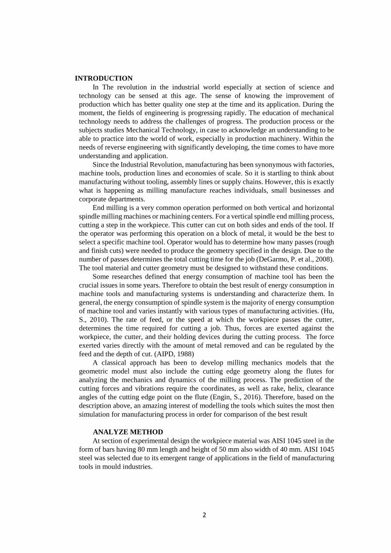
At section of experimental design the workpiece material was AISI 1045 steel in the
form of bars having 80 mm length and height of 50 mm also width of 40 mm. AISI 1045
steel was selected due to its emergent range of applications in the field of manufacturing
tools in mould industries.
3
Figure 1 Part Speciment of AISI 1045.
Post-procedure the simulation on Third Wave AdvantEdge Soft. for finding optimum
parameter process. It can be concluded that after several different geometries of cutting
tools on 2 Flute 3 Flute End Mill, the most optimum tool wear that suites the most with the
operation and tool life for surface finish cutting process is 2 Flute. The real machining
treatment able to be used of becoming the initial data parameter for next reference or
consideration
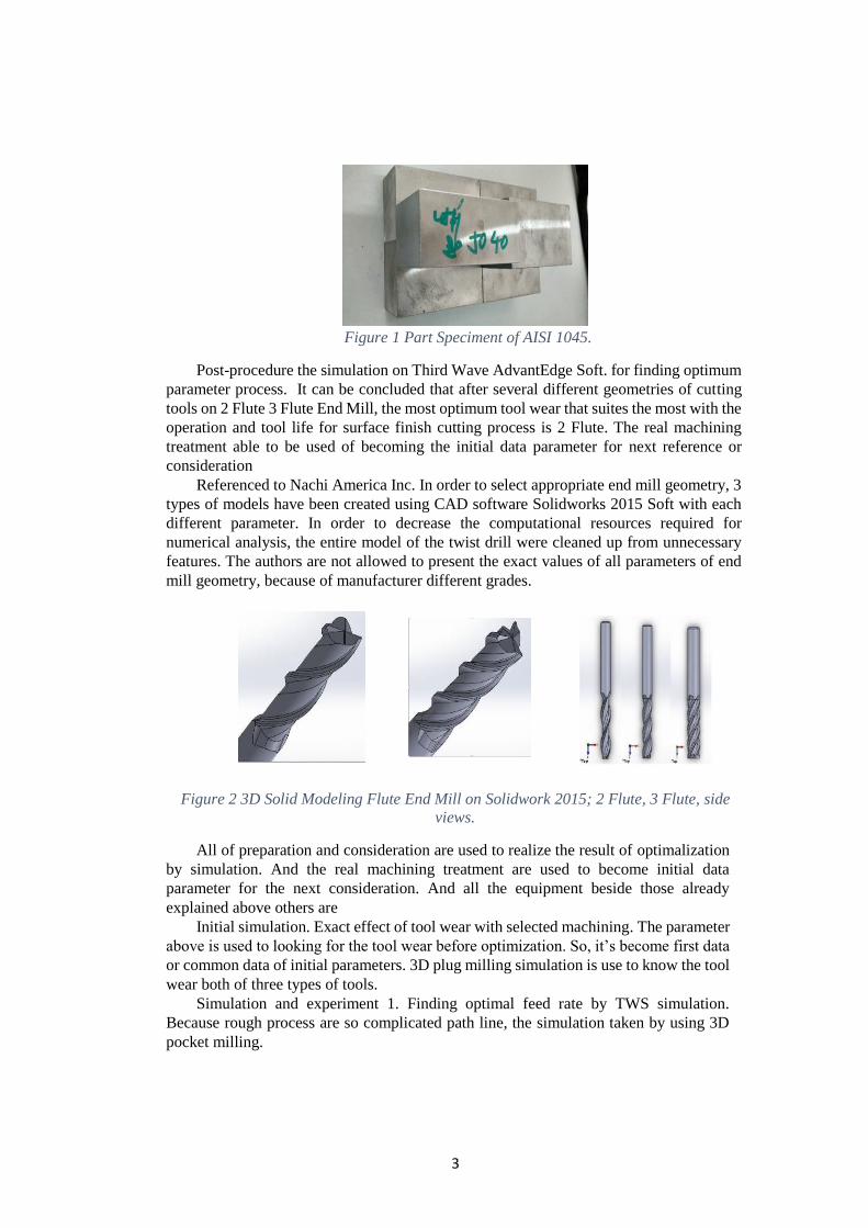
Referenced to Nachi America Inc. In order to select appropriate end mill geometry, 3
types of models have been created using CAD software Solidworks 2015 Soft with each
different parameter. In order to decrease the computational resources required for
numerical analysis, the entire model of the twist drill were cleaned up from unnecessary
features. The authors are not allowed to present the exact values of all parameters of end
mill geometry, because of manufacturer different grades.
Figure 2 3D Solid Modeling Flute End Mill on Solidwork 2015; 2 Flute, 3 Flute, side
views.
All of preparation and consideration are used to realize the result of optimalization
by simulation. And the real machining treatment are used to become initial data
parameter for the next consideration. And all the equipment beside those already
explained above others are
Initial simulation. Exact effect of tool wear with selected machining. The parameter
above is used to looking for the tool wear before optimization. So, it’s become first data
or common data of initial parameters. 3D plug milling simulation is use to know the tool
wear both of three types of tools.
Simulation and experiment 1. Finding optimal feed rate by TWS simulation.
Because rough process are so complicated path line, the simulation taken by using 3D
pocket milling.
4
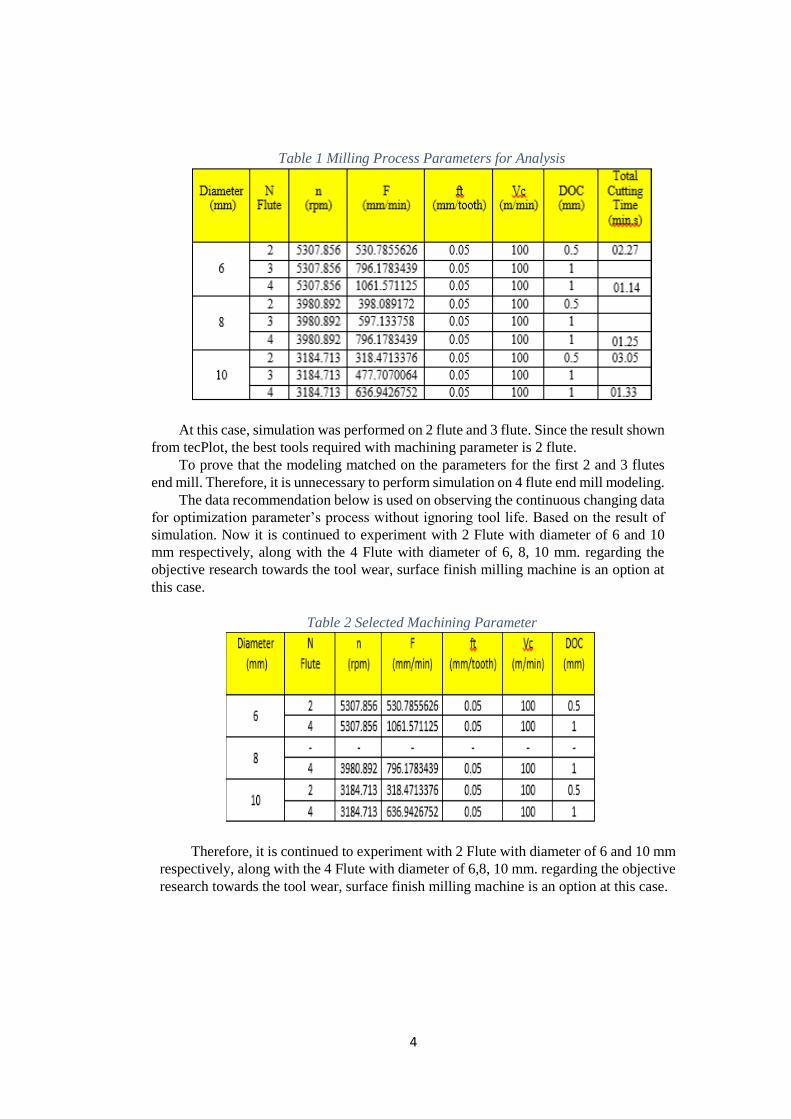
Table 1 Milling Process Parameters for Analysis
At this case, simulation was performed on 2 flute and 3 flute. Since the result shown
from tecPlot, the best tools required with machining parameter is 2 flute.
To prove that the modeling matched on the parameters for the first 2 and 3 flutes
end mill. Therefore, it is unnecessary to perform simulation on 4 flute end mill modeling.
The data recommendation below is used on observing the continuous changing data
for optimization parameter’s process without ignoring tool life. Based on the result of
simulation. Now it is continued to experiment with 2 Flute with diameter of 6 and 10
mm respectively, along with the 4 Flute with diameter of 6, 8, 10 mm. regarding the
objective research towards the tool wear, surface finish milling machine is an option at
this case.
Table 2 Selected Machining Parameter
Therefore, it is continued to experiment with 2 Flute with diameter of 6 and 10 mm
respectively, along with the 4 Flute with diameter of 6,8, 10 mm. regarding the objective
research towards the tool wear, surface finish milling machine is an option at this case.
5
DISCUSSION ANALYZE
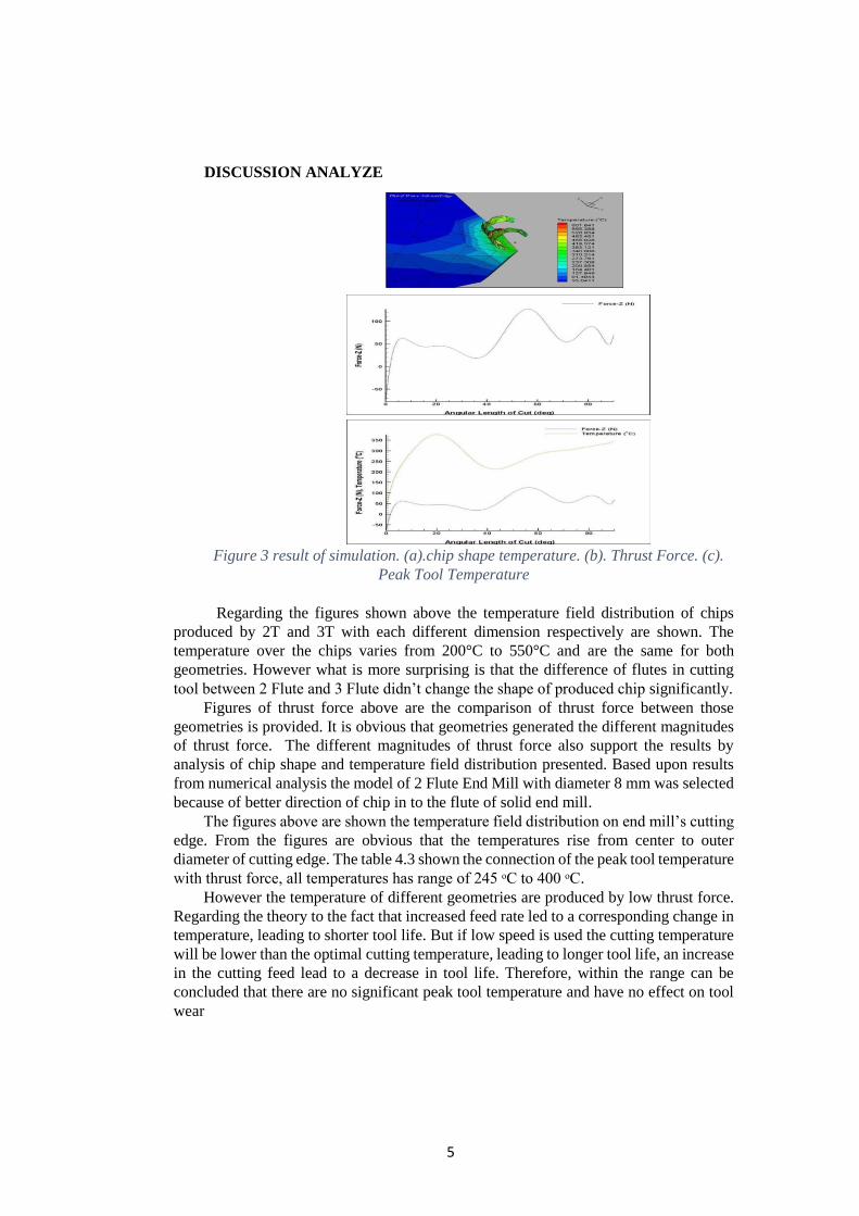
Figure 3 result of simulation. (a).chip shape temperature. (b). Thrust Force. (c).
Peak Tool Temperature
Regarding the figures shown above the temperature field distribution of chips
produced by 2T and 3T with each different dimension respectively are shown. The
temperature over the chips varies from 200°C to 550°C and are the same for both
geometries. However what is more surprising is that the difference of flutes in cutting
tool between 2 Flute and 3 Flute didn’t change the shape of produced chip significantly.
Figures of thrust force above are the comparison of thrust force between those
geometries is provided. It is obvious that geometries generated the different magnitudes
of thrust force. The different magnitudes of thrust force also support the results by
analysis of chip shape and temperature field distribution presented. Based upon results
from numerical analysis the model of 2 Flute End Mill with diameter 8 mm was selected
because of better direction of chip in to the flute of solid end mill.
The figures above are shown the temperature field distribution on end mill’s cutting
edge. From the figures are obvious that the temperatures rise from center to outer
diameter of cutting edge. The table 4.3 shown the connection of the peak tool temperature
with thrust force, all temperatures has range of 245 ᵒC to 400 ᵒC.
However the temperature of different geometries are produced by low thrust force.
Regarding the theory to the fact that increased feed rate led to a corresponding change in
temperature, leading to shorter tool life. But if low speed is used the cutting temperature
will be lower than the optimal cutting temperature, leading to longer tool life, an increase
in the cutting feed lead to a decrease in tool life. Therefore, within the range can be
concluded that there are no significant peak tool temperature and have no effect on tool
wear
6
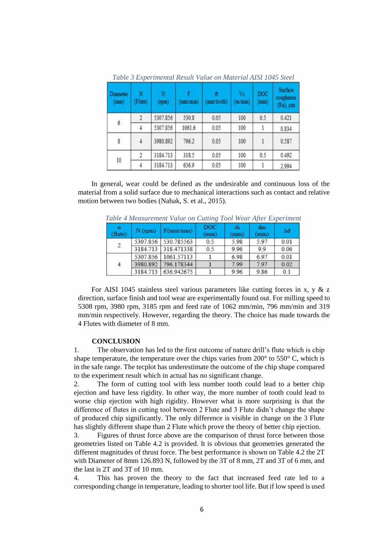
Table 3 Experimental Result Value on Material AISI 1045 Steel
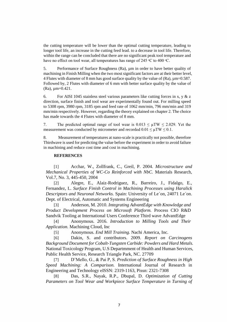
In general, wear could be defined as the undesirable and continuous loss of the
material from a solid surface due to mechanical interactions such as contact and relative
motion between two bodies (Nahak, S. et al., 2015).
Table 4 Measurement Value on Cutting Tool Wear After Experiment
For AISI 1045 stainless steel various parameters like cutting forces in x, y & z
direction, surface finish and tool wear are experimentally found out. For milling speed to
5308 rpm, 3980 rpm, 3185 rpm and feed rate of 1062 mm/min, 796 mm/min and 319
mm/min respectively. However, regarding the theory. The choice has made towards the
4 Flutes with diameter of 8 mm.
CONCLUSION
1. The observation has led to the first outcome of nature drill’s flute which is chip
shape temperature, the temperature over the chips varies from 200° to 550° C, which is
in the safe range. The tecplot has underestimate the outcome of the chip shape compared
to the experiment result which in actual has no significant change.
2. The form of cutting tool with less number tooth could lead to a better chip
ejection and have less rigidity. In other way, the more number of tooth could lead to
worse chip ejection with high rigidity. However what is more surprising is that the
difference of flutes in cutting tool between 2 Flute and 3 Flute didn’t change the shape
of produced chip significantly. The only difference is visible in change on the 3 Flute
has slightly different shape than 2 Flute which prove the theory of better chip ejection.
3. Figures of thrust force above are the comparison of thrust force between those
geometries listed on Table 4.2 is provided. It is obvious that geometries generated the
different magnitudes of thrust force. The best performance is shown on Table 4.2 the 2T
with Diameter of 8mm 126.893 N, followed by the 3T of 8 mm, 2T and 3T of 6 mm, and
the last is 2T and 3T of 10 mm.
4. This has proven the theory to the fact that increased feed rate led to a
corresponding change in temperature, leading to shorter tool life. But if low speed is used
7
the cutting temperature will be lower than the optimal cutting temperature, leading to
longer tool life, an increase in the cutting feed lead. to a decrease in tool life. Therefore,
within the range can be concluded that there are no significant peak tool temperature and
have no effect on tool wear, all temperatures has range of 245 ᵒC to 400 ᵒC.
5. Performance of Surface Roughness (Ra), µm in order to have better quality of
machining in Finish Milling when the two most significant factors are at their better level,
4 Flutes with diameter of 8 mm has good surface quality by the value of (Ra), µm=0.587.
Followed by, 2 Flutes with diameter of 6 mm with better surface quality by the value of
(Ra), µm=0.421.
6. For AISI 1045 stainless steel various parameters like cutting forces in x, y & z
direction, surface finish and tool wear are experimentally found out. For milling speed
to 5308 rpm, 3980 rpm, 3185 rpm and feed rate of 1062 mm/min, 796 mm/min and 319
mm/min respectively. However, regarding the theory explained on chapter 2. The choice
has made towards the 4 Flutes with diameter of 8 mm.
7. The predicted optimal range of tool wear is 0.013 ≤ µTW ≤ 2.029. Yet the
measurement was conducted by micrometer and recorded 0.01 ≤ µTW ≤ 0.1.
8. Measurement of temperatures at nano-scale is practically not possible, therefore
Thirdwave is used for predicting the value before the experiment in order to avoid failure
in machining and reduce cost time and cost in machining.
REFERENCES
[1] Acchar, W., Zollfrank, C., Greil, P. 2004. Microstructure and
Mechanical Properties of WC-Co Reinforced with NbC. Materials Research,
Vol.7, No. 3, 445-450, 2004
[2] Alegre, E., Alaiz-Rodriguez, R., Barreiro, J., Fidalgo, E.,
Fernandez, L. Surface Finish Control in Machining Processes using Haralick
Descriptors and Neuronal Networks. Spain: University of Le´on, 24071 Le´on.
Dept. of Electrical, Automatic and Systems Engineering
[3] Anderson, M. 2010. Integrating AdvantEdge with Knowledge and
Product Development Process on Microsoft Platform. Process CIO R&D
Sandvik Tooling at International Users Conference Third wave AdvantEdge
[4] Anonymous. 2016. Introduction to Milling Tools and Their
Application. Machining Cloud, Inc
[5] Anonymous. End Mill Training. Nachi America, Inc.
[6] Dakin, S. and contributors. 2009. Report on Carcinogens
Background Document for Cobalt-Tungsten Carbide: Powders and Hard Metals.
National Toxicology Program, U.S Departmment of Health and Human Services,
Public Health Service, Research Triangle Park, NC. 27709
[7] D’Mello, G., & Pai P, S. Prediction of Surface Roughness in High
Speed Machining: A Comparison. International Journal of Research in
Engineering and Technology eISSN: 2319-1163, Pissn: 2321-7308
[8] Das, S.R., Nayak, R.P., Dbupal, D. Optimization of Cutting
Parameters on Tool Wear and Workpiece Surface Temperature in Turning of
8
AISI D2 Steel. International Journal of Lean Thinking Volume 3, Issue 2
(December 2012).
[9] DeGarmo, E.P., Black, J.T., Kohser, R.A. 2008. Materials and
Processes in Manufacturing Tenth Edition. United States of America: John
Wiley & Sons. ISBN: 978-0470-05512-0
[10] Engin, S. & Altintas, Y. Tandon, P. Generalized Modeling of
Milling Mechanics and Dynamics: Part I - Helical End Mills. The University of
British Columbia Department of Mechanical Engineering 2324 Main Mall,
Vanocuver, B.C. , V6T 1Z4, Canada
[11] Gupta, P., Dhande, S.G. 2005. Geometric Modeling of End Mills.
Computer-Aided Design & Applications, Vol. 2, Nos. 1-4, 2005, pp 57-65
[12] Hamdan A., Sarhan Ahmed, A.D., Hamdi M. Optimization Method
of The Machining Parameters in High Speed Machining of Stainless Steel using
Coated Carbide Tool for Best Surface Finish. International Journal Adv
Manufacturing Technology, 2012; 58: 81–91.
[13] Hu, S., Liu, F., He, Yan., Peng, B. 2010. Characteristics of
Additional Load Losses of Spindle System of Machine Tools. Journal of
Advanced Mechanical Design, Systems, and Manufacturing. Vol. 4, No. 7, 2010
[14] Jung, S.C. 2010. Reduction of Development Cycle Time Using
AdvantEdge FEM. Korloy Inc: Third Wave AdvantEdge International Users
Conference
[15] Kaladhar, M., Venkata, K., Subbaiah, K.V, Srinivasa Rao, CH.
Optimization of Surface Roughness and Tool Flank Wear in Turning of AISI 304
Austenitic Stainless Steel with CVD Coated Tool. Journal of Engineering Science
and Technology Vol. 8, No. 2 (2013) 165 - 176
[16] Kozmin, P., Sklenicka, J., Roud, P. FEM Method in Chip Shape
and Cutting Force Prediction When Drilling Difficult to Cut Materials. Journal
of Manufacturing 2010 Contemporary problems of manufacturing and
production management 24-26.11.2010 Poznan University of Technology,
Institute of Mechanical Technology, Poland
[17] Kim, J.H., Park, J.W., Ko, T.J. End Mill Design and Machining
Via Cutting Simulation. School of Mechanical Engineering, Yeungnam
University, 214-1 Daedong, Gyoungsan, Kyongbuk, 712-749, Republic of Korea.
Computer-Aided Design 40 (2008) 324-333
[18] Kumar, U., Singh, A., Kumar, R. Optimization of Machining
Parameters for Tool Wear Rate and Material Removal Rate in CNC turning by
Grey Relational Analysis. International Journal of Applied Engineering
Research ISSN 0973-4562 Volume 11, Number 4 (2016) pp 2771-2775.
[19] Kuttolamadom, M.A. 2012. Prediction of The Wear & Evolution
of Cutting Tools in a Carbide/Ti-6Al-4V Machining Tribosystem by Volumetric
Tool Wear Characterization & Modeling. A Dissertation. Clemson University,
Materials Science & Engineering.
[20] Mitrovic, A., Kovac, P., Kulundzic, N., Savkovic, B. 2016. 3D
Finite Element Simulation of Milling. Journal of Production Engineering Vol.19
No.1
9
[21] Montazersadgh, F.H., Fatemi, A. 2007. Stress Analysis and
Optimization of Crankshafts Subject to Dynamic Loading. University of Toledo,
America: Forging Industry Educational Research Foundation (FIERF) & AISI
[22] Nahak, S., Dewangan, S., Chattopadhyaya, S. 2015. Discussion on
Wear Phenomena in Cemented Carbide. GCPF2015 Procedia Earth and
Planetary Science 11 284-293
[23] Nasri, A., Slaimi, J., Bouzid Sai, W. 3D Parametric Modelling of
Milling Cutter Geometry from Analytical Analysis. International Journal of
Science, Technology and Society 2016; 4(2): 35-40. ISSN: 2330-7412
[24] Nithyanandhan, T., Manickaraj, K., Kannakumar, R. Optimization
of Cutting Forces, Tool Wear and Surface Finish in Machining of AISI 304
Stainless Steel Material Using Taguchi’s Method. IJISET - International Journal
of Innovative Science, Engineering & Technology, Vol. 1 Issue 4, June 2014
[25] Noordin, M.Y., Venkatesh, V.C., Sharif, S., Elting, S., Abdullah,
A. Application of Response Surface Methodology in Describing The
Performance of Coated Carbide Tools when Turning AISI 1045 Steel. Journal of
Materials Processing Technology 145 (2004) 46–58
[26] Ojolo, S.J., & Ogunkomaiya, O. 2014. A Study of Effects of
Machining Parameters On Tool Life. International Journal of Materials Science
and Applications 2014; 3(5): 183-199. ISSN: 2327-2635
[27] Park, K.H. 2010. Tool Wear Analysis in Various Machining
Processes and Study of Minimum Quantity Lubrication (MQL). Michigan State
University, Mechanical Engineering Department.
[28] Ramasamy, G. & Ratnasingam, J. 2010. A Review of Cemented
Tungsten Carbide Tool Wear during Wood Cutting Processes. Journal of
Applied Sciences 10 (22): 2799-2804, 2010. ISSN 1812-5654.
[29] Ratnasingam, J., Ma, T.P., Ramasamy, G., Manikam, M. The Wear
Characteristics of Cemented Tungsten Carbide Tools in Machining Oil Palm
Empty Fruit Bunch Particleboard. Journal of Applied Sciences 9 (18): 3397-
3401, 2009. ISSN 1812-5654.
[30] Sarikaya, M., & Gullu, A. 2015. Multi-response Optimization of
Minimum Quantity Lubrication Parameters using Taguchi-based Grey
Relational Analysis in Turning of Difficult-to-Cut Alloy Haynes 25. Journal of
Cleaner Production 91 (2015) 347-357
[31] Sutherland, J.W., Haapala, K.R. Optimization of Steel Production
to Improve Lifecycle Environmental Performance. USA: Dept. of Mech. Engr.-
Engr.Mechs., Sustainable Futures Institute Michigan Technological University
[32] Sarikaya, M. Optimization of The Surface Roughness by Applying
The Taguchi Technique for The Turning of Stainless Steel Under Cooling
Conditions. UDK 621.7.01/.09:519.233:621.941 ISSN 1580-2949 MTAEC9,
49(6)941 (2015)
[33] Tian, G.Y., Lu, R.S., Gledhill, D. Surface Measurement using
Active Vision and Light Scattering. Optics and Lasers in Engineering, 45, 131-
139 (2007)