Embed Size (px)
Citation preview

•Brisk Air
•Penguin
•High Performance
•High Efficiency

PENGUIN low profile COOL ONLY
HEATPUMP
15,000 BTU
13,500 BTU
11,000 BTU
Pre-installed
Heat Strip Option
Pre-installed Controls Option
9” Height
Analog CCC
Non-Ducted Manual

BRISK AIR/PENGUIN Heat Pumps 59146- Manual or
Analog Only.
- Operates down
to 40 degrees.
59136 –Comfort
Control Only
- Operates down
to 32 degrees.
630 series Penguins


Air Conditioning Cycle
Note: Heat is
removed from the
inside air and is
released to the
outside air.

Pressure Temperature Chart Temperature,
Degrees F R22 Pressure
(PSIG) R410A
Pressure (PSIG)
Temperature, Degrees F
R22 Pressure (PSIG)
R410A Pressure
(PSIG)
15 38 70 80 144 235
20 43 78 85 156 254
25 49 87 90 168 274
30 55 97 95 182 295
35 62 107 100 196 317
40 69 118 105 211 340
45 76 130 110 226 364
50 84 142 115 243 390
55 93 155 120 260 417
60 102 170 125 278 446
65 111 185 130 297 476
70 121 200 135 317 507
75 132 217 140 337 540

UPPER UNIT
CAPACITORS
CONDENSOR
EVAPORATOR
BLOWER MOTOR
COMPRESSOR

Refer to DATA TAG 1. Model # 2. Product # 3. Serial #
PG. 33

Amp Draw Per Temperature
Compressor Amps Temperature at AC Outdoor Coil
10.1 Amps 75 Degrees
11.1 Amps 85 Degrees
12.1 Amps 95 Degrees
13.1 Amps 105 Degrees
14.1 Amps 115 Degrees
15.1 Amps 125 Degrees
Design specifications of all Air Conditioners, 95 degrees at AC (outdoor coil),
80 degrees inside, 50% humidity and exactly 115 Volt AC
PG. 33

Degree Split (Differential) A simple test to see if the Unit is operating to Industry Standards
RETURN AIR
DISCHARGE
* Look for an 18-20 degree split * * Must be 70°F or warmer * * Take Humidity into consideration *
PG. 33

Heat Pump Operation
Note: A Heat Pump
is designed to
remove heat from
the outside air and
release it to the
inside air.

Troubleshoot Freeze-Ups
Blocked Duct Loose Cold Control
Reduced
Air Flow
PG. 26

Air leaks can cause Freeze-Ups
PG. 26

Freeze-Ups cont. Items to check when a freeze up occurs:
• RECURCULATION OF COLD AIR
• AIR FLOW (damaged coil, blocked ducts, dirty, filters, etc.)
• Low Charge on Compressor
Note: It is rare that a freeze up is occurring because of a low charge on the compressor.
• Also make sure that the Cold Control is located in the right position and is within specifications.
• Make sure to ask the customer if the freeze-ups are happening at night (i.e., when temperatures are around 60°F.) ☺ Discuss
PG. 26

COLD CONTROL (Freeze sensor) Old Style New Style
PG. 25

CHECK CONTINUITY Used on roof top air
conditioners ONLY.
(If used with a Heat Pump, it will cause premature shut off of the compressor)
Normally OPEN
CLOSED when temperatures are below 45° F +/- 4.
Switch will OPEN at 65° F +/- 5.
PG. 25

COMPRESSOR
CHECK FOR SHORT TO CASE
CHECK FOR OPEN WINDINGS
PG. 23

COMPRESSOR To check for OPEN WINDINGS
1. Disconnect all power and turn
all switches to the “OFF”
position.
2. Disconnect 3 leads going to
compressor (C, R, S).
3. Check for continuity between
all terminals.
4. There SHOULD be continuity.
To check for SHORT to CASE
1. Same as above, but to the
case of compressor.
2. You should NOT have
continuity.
PG. 23

OVERLOAD PROTECTOR
PG. 23
Use an ohmmeter to
check for continuity
through the overload
device. If no continuity is
found and the compressor
is hot, allow 15 to 20
minutes for the
compressor to cool. If a
repeat of this test still
shows the overload to be
open, it is defective and
requires replacement.
NOTE: On some units the overload is an internal
component of the compressor and is non-replaceable.

Condenser Coil
What is the problem with this air conditioner?

Penguin Foam Kit • Installed on Older
Models
• Some New Units have the foam installed on the shroud. • Symptom – High Amps, Tripping Breakers • The foam makes an air tight seal which forces the air through the condenser – Air will travel the path of least resistance if foam is missing, compressed or installed improperly. Plastic Housing

See Bulletin A30-7A Note: If the foam is installed on the shroud and you are getting high amps/breakers tripping, remove foam and call Warranty Department to order foam kit part# 3312081.000. Install Foam Kit on Unit – NOT the shroud.
It is okay to have foam on shroud – only if experiencing problems does it need to be replaced.
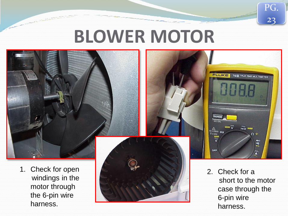
BLOWER MOTOR
1. Check for open
windings in the
motor through
the 6-pin wire
harness.
2. Check for a
short to the motor
case through the
6-pin wire
harness.
PG. 23

CAPACITORS
1. Discharge Capacitors
2. Check continuity with
analog meter or
Microfarad’s with a
digital meter.
WARNING:
Capacitors
are rated at
370 Volts AC.
Identification
located on
capacitor.
PG. 22

START CAPACITOR AND PTCR’S PTCR
PTCR
Start Capacitor
PG. 22

REVERSING VALVE / SOLENOID COIL
The reversing valve is the heart of a heat pump. It changes the
direction of the refrigerant flow through the coils, and changes the
system from cooling to heating and vice versa.
PG. 26
265 OHMS +/- 10%
465 OHMS +/- 10%

Out Door Temperature Sensor
The Change-over thermostat is
a capillary tube/bellows-type
switch. Its function is to shut
the compressor and fan off by
opening the neutral side when
outside temperatures are 40
degrees +/- 10%.
•Used on Heat Pumps Only •Analog and Mechanical
To Test a Change-Over Thermostat
1. Verify temperature at capillary tube.
2. If temperatures are above 45○ F,
continuity SHOULD be between 2 and
3 and NOT between 2 and 1.
3. If temperatures are below 40○ F,
continuity SHOULD be between
terminals 2 and 1 and should NOT be
between 2 and 3.
PG. 17

ANALOG THERMOSTAT Ground Activated
= GROUND
= FAN (LOW)
= FAN (HIGH)
= FURNACE
= COOL (COMPRESSOR)
/ = +7.5
= OPTIONAL HEAT
STRIP/HEAT PUMP
PG. 17/18

ANALOG WIRING at Control Box
= GROUND
= FAN (LOW)
= FAN (HIGH)
= FURNACE
= COOL
(COMPRESSOR)
/ = +7.5
= OPTIONAL HEAT
STRIP/HEAT PUMP
/ = FURNACE (2)
= +12 VDC
• BLACK = -12 VDC
Note: If any of the Low Voltage wires from control box goes to
ground ( ), it SHOULD activate that function.

Verify circuits are being completed through the control box
Never use a volt
meter when
checking a
completed circuit.
Using a 115 Volt AC
incandescent bulb, check from
terminal 5 --( Common)
to other terminals to determine
if a particular circuit is being
completed.
5
PG. 19/20

TIME DELAY
Delays the compressor start up for
2 ½ minutes.
Used when 115 VAC is interrupted
or if the thermostat is inadvertently
turned off and back on again
causing the compressor to quick
cycle under load.
Used to help prevent breaker
tripping and to extend compressor
and compressor relay life.

COMFORT CONTROL CENTER Fully digital system creates up to four
different climate zones from one centralized location.
Operate heat pump, AC, fan and other functions for each zone, up to 4 zones.
Intel-set technology lets you easily change settings; internal memory retains all settings--you never need to reprogram after a power failure.
Sure-Touch control panel features user-friendly, intuitive controls; LCD panel provides readouts in degrees F or C.
AGS system monitors power supply/demand and automatically starts on-board generator as needed.
PG.
18

COMMUNICATION CABLE
A standard telephone cable will NOT work You must have straight through polarity
The communication cable
supplies the thermostat
with 12 VDC. It will also
supply 12 VDC to all other
Zones.
PG. 19


Symptom- No display lights Check Solder joints above the
communication cable
connection on the back side of
the thermostat.
NEGATIVE
POSITIVE
Top Right and
Bottom Left
You should see +12 VDC. If you see – 12 VDC, you
have reversed polarity on communication cable.
PG. 19

SYSTEM RESET
PG. 19
Turn the ON/OFF switch to the “OFF” position.
Simultaneously depress and hold the “MODE” & “ZONE” buttons while
turning the ON/OFF switch to the “ON” position.
“FF” should appear on the display until the “MODE” & “ZONE” buttons are
released.
If “EE” appears when the buttons are released, perform the reset again. If
“EE” keeps displaying, there is a communication problem.
When a dip switch is turned on or off after initial configuration, a reset must
be performed to allow the Comfort Control Center to recognize the updated
change.
Any time a component is added or removed, it is best to perform a reset .
There are no repairs to be done on the Comfort Control Center.

DIP SWITCHES For proper operation,
the dip switches
MUST be set.
1. Heat Strip
2. Zone 2
3. Zone 3
4. Zone 4
5. Furnace
6. Differential
7. Stage
8. Gen Start
PG. 30

Dip Switches have to be set on each control board for the options to be
available to the customer. Heat Strip- If the zone selected has a heat strip, dip switch #1 needs to be
turned on.
Dip switches 2, 3, and 4 are for each additional air conditioner (Zone).
Note: All “ZONE” dip switches OFF, defaults to zone 1.
Furnace- If the air conditioner has a furnace connected, dip switch # 5 needs to be turned on.
Differential- If there is an excessive temperature swing in the furnace mode, dip switch # 6 needs to be turned on. This will cut the temperature swing in HALF.
Stage- Allows Dual-Basement air conditioners to operate off of 1 control board. Dip switch # 7 needs to be turned on.
Gen Start- On vehicles equipped with AGS kit the vehicle generator will automatically start when any zone calls for cooling and will shut down when all zones have reached set point. Dip Switch #8 needs to be turned on.
PG. 30

Temperature Sensors
Ambient
Temperature
Sensor
Remote Temperature
Sensor
Cold Control
PG. 24/25

To test the Ambient Temp Sensor 1. Disconnect 115 VAC.
2. Remove the RED 2-pin
connector from the control
board.
3. Set your meter to OHMs.
4. Probe across both wires to
get an OHMs value.
5. Once you have the value,
compare the reading to the
chart.
6. Check each wire to Chassis
ground. Note: You will still
get a resistance reading if
one wire has gone to ground.
The ambient sensor is the outside air temperature sensor and
used on CCC Heat Pumps Only. Allows the Heat Pump to
operate down to 32°F.
PG. 25

To test the Cold Control 1. Disconnect 115 VAC.
2. Remove the BLUE 2-pin
connector from the control
board.
3. Set your meter to OHMs.
4. Probe across both wires to
get an OHMs value.
5. Once you have the value,
compare the reading to the
chart.
6. Check each wire to Chassis
ground. Note: You will still
get a resistance reading if
one wire has gone to ground.
•Used on both air conditioners and heat pumps. When the
temperature of the coil reaches the freezing point the
compressor will stop operation and the fan will automatically go
to high speed.
PG. 25

To test the Sensor 1. Disconnect 115 VAC.
2. Remove the 2-pin
connector from the control
board.
3. Set your meter to OHMs.
4. Probe across both wires to get
an OHMs value.
5. Once you have the value,
compare the reading to the
chart.
6. Check each wire to Chassis
ground. Note: You will still get
a resistance reading if one wire
has gone to ground.
PG. 24

You are the reason we are here!