Embed Size (px)
Citation preview

British Columbia Carpenter Apprenticeship Program
Level 2 Line B
Use Construction Drawings and Specifications
7960003547
Competency B-1

OrderingCrown Publications, Queen’s PrinterPO Box 9452 Stn Prov Govt563 Superior St. 2nd FlrVictoria, B.C. V8W 9V7
Phone: 1 800 663-6105Fax: 250 387-1120Email: [email protected]: www.crownpub.bc.ca
Copyright © 2012 Industry Training AuthorityThis publication may not be reproduced in any form without permission by the Industry Training Authority.Contact Director, Crown Publications, Queen’s Printer at 250 356-6876.

SAFETY ADVISORYPlease note that it is always the responsibility of any person using these materials to inform him/herself about the Occupational Health and Safety Regulation pertaining to his/her work. The references to WorkSafeBC safety regulations contained within these materials do not / may not reflect the most recent Occupational Health and Safety Regulation (the current Standards and Regulation in BC can be obtained on the following website: http://www.worksafebc.com).

BC CARPENTER APPRENTICESHIP PROGRAM—LEVEL 2 1
Competency B-1Use Construction Drawings and Specifications
ContentsObjectives . . . . . . . . . . . . . . . . . . . . . . . . . . . . . . . . . . . . . . . . . . . . . . . . . . . . . . . . . . . . . . . . . . . . . . . . . . . . . . 2
Learning Task 1: Use Architectural and Structural Drawings . . . . . . . . . . . . . . . . . . . . . . . . . . . . . . . . . . . . . 3
Learning Task 1: Self-Test. . . . . . . . . . . . . . . . . . . . . . . . . . . . . . . . . . . . . . . . . . . . . . . . . . . . . . . . . . . . . . . . . 22
Learning Task 2: Draw Formwork Details . . . . . . . . . . . . . . . . . . . . . . . . . . . . . . . . . . . . . . . . . . . . . . . . . . . 23
Learning Task 2: Self-Test. . . . . . . . . . . . . . . . . . . . . . . . . . . . . . . . . . . . . . . . . . . . . . . . . . . . . . . . . . . . . . . . . 27
Learning Task 3: Coordinate with Other Trades . . . . . . . . . . . . . . . . . . . . . . . . . . . . . . . . . . . . . . . . . . . . . . 29
Learning Task 3: Self-Test . . . . . . . . . . . . . . . . . . . . . . . . . . . . . . . . . . . . . . . . . . . . . . . . . . . . . . . . . . . . . . . . . 33

2 BC CARPENTER APPRENTICESHIP PROGRAM—LEVEL 2
Competency B-1Use Construction Drawings and Specifications
Construction drawings are the guide to the construction of a building; they are the way that the designer describes how to build the building to meet the specifications of the owner. Construction drawings can be very complicated, containing hundreds of sheets. To be able to construct the building, the carpenter must be able to extract specific information and measurements from the drawings.
ObjectivesWhen you have completed the Learning Tasks in this Competency, you will be able to:
• use construction drawings
• use architectural drawings
• use structural drawings
• use contract documents
• describe schedules, shop drawings and reflected ceiling plans
• identify the steps in conflict resolution
• describe formwork details
• describe coordination with other trades
• use specifications
Competencies Written: “Read Construction Drawings” You will be tested on your knowledge of the construction drawings and contract documents.
Practical: You will be required to extract specific information from construction drawings.

BC CARPENTER APPRENTICESHIP PROGRAM—LEVEL 2 3
Notes
COMPETENCy B-1 LEArnInG TASk 1
Learning Task 1Use Architectural and Structural Drawings
BC Building Code (BCBC) requires the following building types to be designed by a registered professional:
• large buildings over 600 m2 (6450 ft2) in floor area
• buildings more than three storeys in height
• buildings with assembly, care or detention type occupancies
• high hazard factories
A registered professional is defined as either an architect or engineer.
These buildings fall under Part 3 of the building code. A registered professional must verify through field reviews that the work was done properly.
Commercial and Larger Buildings Normally architects design Part 3 buildings and the architect may employ a registered professional engineer to do the structural design. The architect may also employ other professionals to design the electrical, plumbing and heating systems. Usually, the architect or an engineer will act as the project manager during the construction process.
Drawings of larger buildings are usually broken into the following to make them easier to read and more applicable to those using them:
• architectural drawings
• structural drawings
• electrical drawings
• mechanical drawings
Typically, carpenters use the architectural and structural drawings.

Notes
4 BC CARPENTER APPRENTICESHIP PROGRAM—LEVEL 2
LEArnInG TASk 1 COMPETENCy B-1
MeasurementsBuilding dimension measurements normally extend from building lines and gridlines. Building lines are the lines formed by the exterior of the foundation or the exterior of the wall.
Larger projects will have a series of gridlines. Gridlines are lettered in one direction and numbered in the other direction. Gridlines are often centered to major building components, such as beams and columns. Gridlines do not change from drawing to drawing or from floor to floor, and are used for layout purposes. An example of gridline use is shown in Figure 1.
21 3 4 5
A
B
C
D
E
EXTEND OF PILE
FOUNDATION
FOOTING TYPE - A FOOTING TYPE - A
FOOTING TYPE - B
FOOTING TYPE - B
FOOTING
TYPE - B
PILE CAP TYPE - A
PILE CAP TYPE - B
TYPICAL WALL FOOTING
850 × 350
ELEVATOR FOOTING
5900 × 4600 × 650
5900
46
00
5700 5700 5700 5700
65
50
65
50
65
50
65
50
PILE CAP TYPE - B
1000
TYP
150
TY
P
PILE CAP TYPE - C
TYP.
SLAB THICKNESS
200
1
S8
S8
5
3275
3275
3275
3275
1425
2425 3275 3275 2425
1425
Figure 1. Example of gridline use

BC CARPENTER APPRENTICESHIP PROGRAM—LEVEL 2 5
Notes
COMPETENCy B-1 LEArnInG TASk 1
Architectural Drawings Architectural drawings are used to show building size, building shape, exterior finish details, interior finish details and room use. The architectural drawings include floor plans, elevation views, cross sections and details.
Drawing Numbers In sets of drawings that include a combination of architectural, structural, electrical and mechanical drawings, the drawing numbers have the first letter of the discipline as a prefix. For example ‘A1’ is the first architectural drawing and ‘S5’ is the fifth structural drawing.
Floor Plans In a set of construction drawings, the floor plans are near the beginning because they provide the reference for most of the construction information in the drawings. When looking at floor plans you are looking down on the building from overhead. Floor plans are drawings that use symbols to indicate the building components.
revisions When using construction drawings, make sure you are using the most up-to-date version of the drawing.
During a construction project, new drawings may accompany change orders, and should be included with the original drawings. The changes should be clearly noted and drawings dated so that there can be no mistake about which drawing is the most recent.
Revisions to construction drawings are noted on the drawing and identified in the title block. The revisions are indicated in the title block with a symbol, and the corresponding revision is shown on the drawings with the same symbol. Often a revision cloud is drawn around the portion of the building that was changed (Figure 2).
As-Built Drawings As part of the contract to complete a larger building, the building contractor is normally required to provide the owner with a set of as-built drawings. The purpose of these drawings is to show where the electrical and mechanical systems were installed as well as any changes that were made during construction. Changes should be identified with revision clouds as mentioned previously. As-built drawings are often useful for maintenance work, and future renovations and retrofits.

Notes
6 BC CARPENTER APPRENTICESHIP PROGRAM—LEVEL 2
LEArnInG TASk 1 COMPETENCy B-1
UP
R7
Figure 2. Revision cloud indicating the extent of the revision
Use Structural Drawings Structural drawings are primarily used for the construction of larger commercial buildings. They show structural and construction details. A very tall building will have additional structural requirements in addition to load bearing. These will include seismic and wind loads.
The wind load on tall buildings must be considered in the design. The Columbia Seafirst Center in Seattle, Washington is 76-stories and 291 m (995 ft) tall. The wind force on the Seafirst Center has been calculated at 15 million pounds during a gale. This would easily push the very tall, slender, building around. To counteract the harmonic movement in tall buildings such as this one, dampers are positioned at the top of the building, which absorb the energy of wind gusts. The dampers consist of heavy weights in a container of heavy liquid, which counters the movement of the building.
Construction Details Plan and elevation drawings for larger projects have to be drawn to a smaller scale (usually 1:100) to allow the whole footprint of the building to fit on a standard sheet of drawing paper. The smaller scale of the plan and elevation drawings doesn’t allow for adequate detail to be shown.

BC CARPENTER APPRENTICESHIP PROGRAM—LEVEL 2 7
Notes
COMPETENCy B-1 LEArnInG TASk 1
Detail drawings and large-scale cross sectional drawings (1:25 or 1:50) are required to describe the construction. Symbols indicate where these drawings are found.
A set of structural drawings for a larger project may consist of 30 to 50 sheets of drawings.
Footings and Foundations The loads applied to the footings for commercial buildings are significantly larger due to the weight and height of the buildings. Footing sizes for commercial buildings must be greater than footing sizes for residential buildings. Footing sizes may be shown in cross sections, details or in a schedule.
21 3 4 5
A
B
C
D
E
EXTEND OF PILE
FOUNDATION
FOOTING TYPE - A FOOTING TYPE - A
FOOTING TYPE - B
FOOTING TYPE - B
FOOTING
TYPE - B
PILE CAP TYPE - A
PILE CAP TYPE - B
TYPICAL WALL FOOTING
850 × 350
ELEVATOR FOOTING
5900 × 4600 × 650
5900
46
00
5700 5700 5700 5700
65
50
65
50
65
50
65
50
PILE CAP TYPE - B
1000
TYP
150
TY
P
PILE CAP TYPE - C
TYP.
SLAB THICKNESS
200
1
S8
S8
5
3275
3275
3275
3275
1425
2425 3275 3275 2425
1425
Figure 3. A portion of a sheet of the 5-storey commercial building

Notes
8 BC CARPENTER APPRENTICESHIP PROGRAM—LEVEL 2
LEArnInG TASk 1 COMPETENCy B-1
Cross Section and Detail Notation On drawings of larger buildings there could be hundreds of cross sections and details. To keep them all organized, a specific notation is used.
A section or detail notation uses two numbers; the top number is the cross section or detail number, and the bottom number is the drawing page number where the section or detail drawing is found.
1
S8
Figure 4. Section notation
S8
5
Figure 5. Detail notation
A section notation includes an arrow that shows the direction that the cross section is looking. The horizontal line in the section notation is where the actual cut of the section is made. For example the section notation shown in Figure 4 is for section 1, and is from the foundation plan shown in Figure 3. Section 1 is cut through the foundation wall and is looking north. The actual drawing of section 1 is on structural drawing number 8, and is shown in Figure 8.
1
S2WALL SECTION
Figure 6. Cross section title
S2
5PILE CAP DETAIL
Figure 7. Detail title
The title of the wall section shown in Figure 6 is for the foundation wall section shown in Figure 8.
The two numbers in the titles indicate the section or detail number and where in the set of drawings that section or detail notation is found.

BC CARPENTER APPRENTICESHIP PROGRAM—LEVEL 2 9
Notes
COMPETENCy B-1 LEArnInG TASk 1
Footing and Wall Sections The cross section of the concrete footing and wall is used to show the dimensions of the members, the reinforcing steel, elevations and inserts and anchors.
Due to site considerations, the foundation for the 5-storey building includes both deep and shallow foundation systems. Figure 8 is the typical wall section for the shallow foundation system for the building.
SLOPE
250
350
850
200
ELEV. 7.385
ELEV. 10.295
25 mm ASBDRAINAGE MAT
3.5 mm FILTER LAYER
40 mm Ø DRAINAGE MATERIAL
150 mm Ø DRAINAGE PIPE
100 mm VINYLWATER STOP
19 mm ISOLATIONJOINT MATERIAL
1S2
WALL SECTION
TWO LAYERS20 M @ 300 o.c. e.w.
20 M @ 400 o.c. e.w. TOP AND BOTTOM
20 M @ 250 o.c. e.w.TOP AND BOTTOM
This wall section is from the second sheet of the structural drawings.
Figure 8. Wall section
Section view drawings have extensive detail and material information, but for specific material identification, the builder will have to refer to the specifications book.

Notes
10 BC CARPENTER APPRENTICESHIP PROGRAM—LEVEL 2
LEArnInG TASk 1 COMPETENCy B-1
Footing and Wall Details Detail views are usually plan or elevation views. The pile cap shown in Figure 9 is complicated and would require that a copy of the drawing be made and kept on site. Steel piles usually extend into the pile cap by 75 mm (3”). Reinforcing in columns is tied into the pile cap with dowels.
500 173
189
677
346
D
2, 3 & 4
300 mm STEELPILE ASTM A36
DRIVEN TO REFUSAL
400
75
300 × 300CONCRETE
COLUMN
2, 3 & 418
9
327
377
20 M @ 250 o.c. e.w.TOP AND BOTTOM
4 - 20 M DOWELS h1e
PLAN VIEW ELEVATION VIEW
PILE CAP DETAIL5
S2
Figure 9. pile cap details
The depth of pile foundations is not shown on the drawing because the length of the pile is only determined as it is being driven. The steel piles come in 30 to 40 foot lengths, and additional piles can be welded onto the previous ones to allow for depths of over 100 feet.
The piles are driven to refusal, which means that the driving continues until the pile cannot be driven any deeper. The engineer on site determines the point of refusal. When the pile is completely driven, the excess is cut off with a cutting torch. A cage of reinforcing bars is placed into the pile and the pile is filled with concrete.
The pile cap’s job is to transfer the weight of the building down to the piles, which in turn transfer the load down to solid bearing, well below the surface of the ground.

BC CARPENTER APPRENTICESHIP PROGRAM—LEVEL 2 11
Notes
COMPETENCy B-1 LEArnInG TASk 1
Structural Steel The common structural steel shapes are shown in Figure 10. The standard designation for structural steel is made up of three parts:
1. L, S, W and C to designate Angle iron, Standard beam, Wide Flange beam and Channel iron.
2. The member depth.
3. The weight of the member per feet or metre of length.
An example of the designation is W 200 × 27, which means a Wide Flange beam that is 200 mm deep and weighing 27 kilograms per lineal metre.
L - ANGLE
IRON
S - STANDARD
FLANGE BEAM
W - WIDE
FLANGE BEAM
C - CHANNEL
IRON
Figure 10. Standard structural steel shapes
Structural Steel DrawingsDrawings of structural steel elements are usually schematic in nature. Simple line drawings are used to show the location and size of the members, as shown in Figure 11.
C
1
C
2 3
W 250 × 33
W 2
50 ×
24
W 2
50 ×
24
W 2
50 ×
24
W 250 × 33
Figure 11. Plan view of structural steel beams

Notes
12 BC CARPENTER APPRENTICESHIP PROGRAM—LEVEL 2
LEArnInG TASk 1 COMPETENCy B-1
Girders and Beams Girders and beams are shown on plan views as dashed lines. The dimensions are often shown on cross section drawings of the beams, but in some cases they are shown in a beam schedule, similar to the footing schedule.
Drawings Showing Steel Reinforcing On structural drawings, the reinforcing bar is shown in several ways. In footings and walls, the bars are identified in the section drawings or detail drawings.
Reinforcing in slabs and beams is shown as individual bars. The individual bars are shown to indicate how they are to be overlapped. Figure 12 is an example.
5700 5700
655
0
20 M @ 300 O.C.
TOP AND BOTTOM
15 M @ 300 O.C.
TOP AND BOTTOM
20 M @ 300 O.C.
TOP AND BOTTOM
15 M @ 300 O.C.
TOP AND BOTTOM
Figure 12. Slab reinforcing notation on a plan view
The heavy black lines in Figure 12 are the actual bars, the notation gives the size and spacing of the bars and lines with the arrows show where the bars are to be placed.

BC CARPENTER APPRENTICESHIP PROGRAM—LEVEL 2 13
Notes
COMPETENCy B-1 LEArnInG TASk 1
Schedules Schedules provide information about building components. It is much more efficient to layout the specifications for each door or window only once in the schedule as opposed to multiple times on the drawings.
For example a schedule is often used for commercial construction where there may be 50 components that are all the same size and specification. A symbol is used on the drawing to indicate the component; refer back to the schedule to find its description.
Footing and Pile Cap Schedule Where there are many footings or pile caps, a schedule is established to describe each one (Figure 13).
Footing and Pile Cap Schedule
Member Dimensions Reinforcing notes
Footing–A 1200 × 1200 × 350 mm 2 Mats of 25 M bars @250 o.c. e.w.
T.O. Footing Elev. 7.135 m
Footing–B 1200 × 1200 × 350 mm 2 Mats of 20 M bars @250 o.c. e.w.
T.O. Footing Elev. 7.135 m
Pile Cap–A See Detail 1 on S8 3 – 20 M bars in each pile T.O. Pile Elev. 7.210 m
Pile Cap–B 1200 × 1200 × 350 mm 6 – 20 M Longitudinal bars with 20 cross bars @ 250 o.c. 3 – 20 M bars in each pile
T.O. Pile Cap Elev. 7.135 m
T.O. Pile Elev. 7.210 m
Pile Cap–C N. A. 3 – 20 M bars in each pile T.O. Pile Elev. 7.210 m
Figure 13. Footing and pile cap schedule

Notes
14 BC CARPENTER APPRENTICESHIP PROGRAM—LEVEL 2
LEArnInG TASk 1 COMPETENCy B-1
Door Schedule Door schedules provide door sizes, materials, style, hardware requirements and other special notes. Each door is indicated by a symbol on the floor plan, usually a letter in a circle or square. The corresponding letter is used in the door schedule. Figure 14 shows a typical door schedule.
Door Schedule
Door Frame
Thre
shol
d
Wea
ther
STr
rem
arks
Type
Size
(Width × height × thickness)
Mat
.
Core
Fin
Clos
er
Mat
eria
l
Fin
A 750 × 2100 × 45 ALUM HOLLOW ANOD YES ALUM ANOD YES YESDOUBLE GLAZED
B 810 × 2100 × 45 DO DO PT. NO STEEL PT YES NOLOCK
AND KEY
C 910 × 2030 × 45 WOOD DO DO DO DO DO NO DO
D 610 × 2030 × 45 DO SOLID DO DO DO DO YES DO
E 750 × 2100 × 35 DO HOLLOW DO DO WOOD DO NO DO
F 810 × 2100 × 35 DO DO DO DO DO DO DO DO
G 910 × 2030 × 35 DO DO DO YES DO DO DO DO
Figure 14. Door schedule (note: in this schedule DO stands for Ditto)

BC CARPENTER APPRENTICESHIP PROGRAM—LEVEL 2 15
Notes
COMPETENCy B-1 LEArnInG TASk 1
Window Schedule Drawings are often used as part of a schedule when there are graphic details that need to be described. Figure 15 shows a typical window schedule. The drawing shows the shape and dimensions of the window as well as the opening of the sash.
The schedule shown in Figure 15 uses a hexagon with the window number as a symbol.
W1
2557 2557
1179
1526
1526 1526
1793 1030
FIXED
W2
W4W3
Figure 15. Window schedule
In concrete or masonry construction, the finished opening sizes for the windows are shown on the drawings. Standard window sizes are sometimes used, but windows are often custom built to fit the concrete openings.
Stock windows are used in wood frame construction. This requires that the rough opening in the framing be built to suit the windows being ordered.
Check with the window manufacturer to determine the rough opening sizes before framing walls.

Notes
16 BC CARPENTER APPRENTICESHIP PROGRAM—LEVEL 2
LEArnInG TASk 1 COMPETENCy B-1
room Schedule Room schedules provide the information for the finishes of each room in the building. The wall, ceiling and floor finishes are specified as well as the type of material used for the baseboards.
Room name or room number lists the rooms described in a room schedule.
room Schedule
room Base Floor Wall Ceiling
Rem
arks
Material Fin Material Fin Material Fin Material Fin
GARAGE NONE - CONC.
EXPO
SED CONC. PT GYP. PT -
LOBBY VINYL - QUARRY TILE
SEAL
ER
MARBLE - SUSP CEILING
- -
STORAGE DO - VINYLW
AXCONC. PT GYP. PT -
PARKING NONE - CONC.
TRO
WEL CONC. - CONC. - -
RM 120 WOOD PT CARPET - GYP. PT GYP PT -
RM 220 WOOD PT DO - DO DO DO DO -
Figure 16. Typical room schedule

BC CARPENTER APPRENTICESHIP PROGRAM—LEVEL 2 17
Notes
COMPETENCy B-1 LEArnInG TASk 1
Shop drawings and Reflected Ceiling Plans
Shop Drawings The manufacturers of some building components are required to make shop drawings for their components. Cabinet manufacturers, structural steel contractors and window manufacturers all use shop drawings to detail how their components are going to be built and installed. The architect or project manager approves the shop drawings before the manufacturer begins construction of the components.
Copies of the approved shop drawings are sent to the construction site where they are to be used to verify the final dimensions and details. For example, the cabinet shop drawings are used to position the partitions around the cabinets. The partitions must be exactly placed because they are completely finished before the cabinets are delivered to the job.
Approved shop drawings will take precedence over the construction drawings.
250 250
15
35
180
35
35
83
1583
35
25 mm Ø
25
15 mm BOLT PLATE
65
30
60
30
65
19 mm Ø
15 mm PLATE
STEEL
15 mm BOLT PLATE
Figure 17. Typical shop drawing for a structural steel component
Specialties Specialty items are often accompanied by shop drawings. Specialty items may include, but not be limited to, vaults, fixtures, rolling window shutters, hoists and loading dock levelers. These special items all need specific allowances made for them in the construction of the building, and the approved shop drawings will have to be followed carefully.

Notes
18 BC CARPENTER APPRENTICESHIP PROGRAM—LEVEL 2
LEArnInG TASk 1 COMPETENCy B-1
Reflected Ceiling Plans Reflected ceiling plans are used to indicate the ceiling finish as well as the location of lighting fixtures. Figure 18 is an example of a reflected ceiling plan; the ceiling finish and fixture details are indicated with symbols.
E
D
RETAIL SPACE
7700 × 9400
"T" BAR CEILING
RECESSED FLORESCENT
FIXTURE
Figure 18. Typical reflected ceiling plan
Hardware and Fittings Door, window and other hardware will come with installation instructions and details. Although not part of the construction drawings, these details are necessary to correctly install the hardware.
Save the instructions for hardware installation and store them with the documents for the building. They may be required for maintenance, warranty or renovations at a later date.

BC CARPENTER APPRENTICESHIP PROGRAM—LEVEL 2 19
Notes
COMPETENCy B-1 LEArnInG TASk 1
SpecificationsSpecifications are a detailed description of work to be done and the methods by which this work must be done. The specifications book includes writing only; there are no drawings. The text of the specifications is where the designer is able to be very specific about the construction process and the products used in the construction industry
The specifications are divided into 16 standard divisions established by the Construction Specifications Institute (CSI) and are used by the building industry across North America.
CSI Division: 01 - General Requirements
CSI Division: 02 - Site Construction
CSI Division: 03 - Concrete
CSI Division: 04 - Masonry
CSI Division: 05 - Metals
CSI Division: 06 - Wood and Plastics
CSI Division: 07 - Thermal and Moisture Protection
CSI Division: 08 - Doors and Windows
CSI Division: 09 - Finishes
CSI Division: 10 - Specialties
CSI Division: 11 - Equipment
CSI Division: 12 - Furnishings
CSI Division: 13 - Special Construction
CSI Division: 14 - Conveying Systems
CSI Division: 15 - Mechanical
CSI Division: 16 - Electrical
Using the 16 standard divisions simplifies the creation and management of the specifications.
In 2004 the CSI expanded the number of divisions from 16 to 50 divisions to reflect innovations in the construction industry. This system is gaining popularity.

Notes
20 BC CARPENTER APPRENTICESHIP PROGRAM—LEVEL 2
LEArnInG TASk 1 COMPETENCy B-1
Contract Documents The contract documents consist of all written and graphic materials used for design and construction of a project, including the articles of agreement, the definitions, the general conditions, supplementary conditions and the design documents. The design documents are made up of the drawings and the specifications. The contract is divided into the following sections:
• Articles of agreement are those things unique to every contract. They include the parties’ names and addresses, job description and location, and payment details.
• The definitions clarify the meaning of specific terms within the contract.
• General conditions are the standard “boiler plate” clauses that are in most contracts to protect both parties. They deal with items such as changes, defective work, strikes, insurance, bonding and similar issues.
• As some of the general conditions may need changing for a particular project, additional clauses are added. These are known as supplemental conditions and are added on to the end of the contract.
Drawings Plans, shop drawings and other graphic detail make up the drawings. Material and finishing schedules may be part of the plans. The drawings are referenced by the articles of agreement and may be defined in the definitions.
Specifications The specifications for large projects are often the size of a book. They are a detailed description of work to be done and the methods by which this work must be done. The text of the specifications allows the designer to be very specific about the construction process and the products used.
Whenever two parties agree to work together, a contract is formed; the contract may be verbal or written. Verbal contracts are just as binding as written contracts, but are easily disputed and should not be used in construction.
Standard contracts are typically used. They have been developed and proven over time to meet the needs of both contractors and owners. These are produced by the Canadian Construction Association (CCA contracts) and the Canadian Construction Documents Committee (CCDC contracts).

BC CARPENTER APPRENTICESHIP PROGRAM—LEVEL 2 21
Notes
COMPETENCy B-1 LEArnInG TASk 1
Contract Document ranking OrderUnfortunately, when dealing with large projects, conflicts within the contract documents will occur. The architect or project manager should always be contacted when discrepancies occur within contract documents. Case law typically reflects the following four points:
1. If there is a conflict within Contract Documents, the order of priority of documents, from highest to lowest, shall be:
• the Agreement between the Owner and the Contractor
• the Definitions
• Supplementary Conditions
• the General Conditions
• the specifications
• material and finishing schedules
• drawings (plans)
2. Drawings of larger scale govern over those of smaller scale of the same date.
3. Dimensions shown on drawings shall govern over dimensions scaled from drawings.
4. Later dated documents shall govern over earlier dated documents of the same type.
Now complete Learning Task 1 Self-Test.

22 BC CARPENTER APPRENTICESHIP PROGRAM—LEVEL 2
LEArnInG TASk 1 COMPETENCy B-1
Learning Task 1 Self-Test
1. Using the BC Building Code definitions, what is a registered professional?
2. What are gridlines used for?
3. Explain what an as-built drawing is.
4. What is a revision cloud?
5. Why are drawings for larger buildings drawn to a smaller scale than the drawings for residential buildings?
6. What is the purpose of a pile cap?
7. How are footing sizes shown on the drawings for a larger job?
8. What would a W 250 × 20 notation for a structural steel beam indicate?
9. Describe how reinforcing steel is shown on a plan view of a drawing.
10. When are schedules used on construction drawings?
11. When are drawings used as part of a schedule?
12. List two types of building components that can be described in a schedule other than doors, windows or rooms.
13. What should be done prior to framing window openings in a building?
14. What additional information can be found in a window schedule other than the size of the window?
15. What is the height of a door that is listed as a “920 × 1020 × 45”?
16. List two types of information that will be shown on reflected ceiling plans.
17. What should be done with the instructions for installing the panic hardware on the entrance doors of a building after the hardware has been installed?
18. Who draws the shop drawings?
19. What is done with the shop drawings after they are drawn?
20. How does the carpenter use shop drawings?
21. If a schedule specified #2 S-P-F, the plans indicated #2 D.fir, and the specifications book showed #1 S-P-F, which would be the correct choice to use? Should the project manager be contacted regarding this?

BC CARPENTER APPRENTICESHIP PROGRAM—LEVEL 2 23
Notes
COMPETENCy B-1 LEArnInG TASk 2
Learning Task 2Draw Formwork Details
Carpenters must be able to create simple drawings to follow when working as a group to complete a task. The ability to create usable drawings that convey all the needed information is a talent that is usually developed with practice. Drawings are created to convey specific information.
SLOPE
250
350
850
200
ELEV. 7.385
ELEV. 10.295
25 mm ASBDRAINAGE MAT
3.5 mm FILTER LAYER
40 mm Ø DRAINAGE MATERIAL
150 mm Ø DRAINAGE PIPE
100 mm VINYLWATER STOP
19 mm ISOLATIONJOINT MATERIAL
TWO LAYERS20 M @ 300 o.c. e.w.
20 M @ 400 o.c. e.w. TOP AND BOTTOM
20 M @ 250 o.c. e.w.TOP AND BOTTOM
Figure 1. Foundation detail section
The section drawing shown in Figure 1 gives elevation details for those who are constructing the forms. It gives information for placing and tying the reinforcing bars. It also gives information on drainage and slope for backfill. In a situation like this, the picture is most likely worth a thousand words. It is also much easier to understand than a thousand words.
Drawing Formwork PlansDrawing formwork is usually a fairly simple task. The first step is to determine what the people who will be doing the forming need to know. Normally, a plan view and a cross section will be enough to convey the needed information. Additional detail drawings may be required to show connections or any unusual or special forming needs or methods.

Notes
24 BC CARPENTER APPRENTICESHIP PROGRAM—LEVEL 2
LEArnInG TASk 2 COMPETENCy B-1
Information to be IncludedDimensions are one of the most useful parts of most drawings and are often lacking. Dimensions should be provided for all concrete members that are being formed and for most forming components. The location of the concrete members in relation to gridlines is needed for layout and positioning the forms.
Other information should include species and grades of lumber, falsework, and spacing of repetitive material such as ties, studs, walers, joists, shores and braces.
89×89 SHORE HEAD 1.22 m o.c.
89×
89 S
HO
RE
PO
ST
38×89 LEDGER
38×89 STIFFENER 400 o.c.
38×89 KICKER
38×140×300 WEDGES
ON CONTINUOUS 38×235 MUDSILLS
19×140 B
RACE
38×89
38×89 TOP PLATE
38×140 JOISTS 400 o.c.
300 mm
150 mm
150 mm
551 m
m
2-38×235 SCAFFOLDING PLANKS
20 mm FORMPLY
DBL WALER & SPANDREL TIE
Figure 2. Beam and slab formwork section
Figure 2 shows a section of formwork for a monolithic spandrel beam and slab. In addition to the information noted previously, drawings should also include drawing titles, page numbers, dates, scale drawn at and the name of the draftsperson.

BC CARPENTER APPRENTICESHIP PROGRAM—LEVEL 2 25
Notes
COMPETENCy B-1 LEArnInG TASk 2
Formwork Cross Sectional Drawings
1. The first step in drawing a formwork cross section is to draw the concrete. In Figure 2, the beam is 300 mm wide by 551 mm deep. Normally width is given, then height. The slab in the drawing is 150 mm thick.
2. Once the concrete members are drawn, then the sheathing is drawn. This may be 1×8, plywood, steel or other material. The purpose of the sheathing is to support the concrete.
3. Next, draw the support for the sheathing. This may include joists, stiffeners, studs and walers.
4. Joists often need support from stringers (beams) and walers may require strongbacks.
5. Next, falsework is shown. This includes all bracing and shoring.
6. After all drawing is complete, labelling and notations are added.
Checking the DrawingThe drawing in Figure 2 is missing some critical information. Sometimes, to discover what is missing, the draftsperson needs to mentally build the formwork step by step. The first step is to complete layout using the gridlines. Next, the height of the shores is determined—and this piece of information is missing from Figure 2.
Height to top of slab (TOS) should be shown, as well as the height to the bottom of the beam. Although the carpenter building the forms could work from TOS and subtract 551 mm, it will slow work down, and there is an extra chance of error. Another important piece of missing information is the spacing of the ties.

Notes
26 BC CARPENTER APPRENTICESHIP PROGRAM—LEVEL 2
LEArnInG TASk 2 COMPETENCy B-1
Formwork Plan View Drawings The process for drawing a formwork plan view is similar to doing a cross section. The first step is to determine what the drawing needs to show. If it is to indicate the location of joists, stringers and shores, then concrete members might not be shown unless the members help with layout.
As plan views are shown from the top down, dashed lines are used to show that a forming member is under or behind another member (Figure 3).
1
7
5
7
4
73
7
6
7
7
7
21 3 4
2
7
BLDG.
CENTRE
LINE
200
2 438 2 438 2 438
200
100
100
300
600
300
Typ.
30
0
750
3 5
08
1 5
54
844
30
0
200
Ø
850x1395
DOOR
BUCK
c/w
REVERSE
KEY FOR
JAMB
SUPPORT
3 6
58
3 6
58
7 3
16
ALL
DOME
PANS
ARE
EQUAL
AA
Drawn by: Gary Backlund
Date: September 30, 2006
Scale: 1:50
Page 1 of 2Plan View
Figure 3. Plan view
Now complete Learning Task 2 Self-Test.
BC CARPENTER APPRENTICESHIP PROGRAM—LEVEL 2 27
COMPETENCy B-1 LEArnInG TASk 2
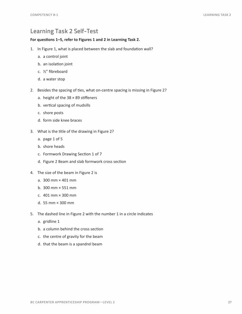
Learning Task 2 Self-TestFor questions 1–5, refer to Figures 1 and 2 in Learning Task 2.
1. In Figure 1, what is placed between the slab and foundation wall?
a. a control joint
b. an isolation joint
c. ½” fibreboard
d. a water stop
2. Besides the spacing of ties, what on-centre spacing is missing in Figure 2?
a. height of the 38 × 89 stiffeners
b. vertical spacing of mudsills
c. shore posts
d. form side knee braces
3. What is the title of the drawing in Figure 2?
a. page 1 of 5
b. shore heads
c. Formwork Drawing Section 1 of 7
d. Figure 2 Beam and slab formwork cross section
4. The size of the beam in Figure 2 is
a. 300 mm × 401 mm
b. 300 mm × 551 mm
c. 401 mm × 300 mm
d. 55 mm × 300 mm
5. The dashed line in Figure 2 with the number 1 in a circle indicates
a. gridline 1
b. a column behind the cross section
c. the centre of gravity for the beam
d. that the beam is a spandrel beam

28 BC CARPENTER APPRENTICESHIP PROGRAM—LEVEL 2
LEArnInG TASk 2 COMPETENCy B-1
6. What is the main purpose of a formwork drawing?
a. to convey needed information
b. to support the fresh concrete
c. to show tie spacing
d. to meet WorkSafeBC requirements
7. The first step in drawing a concrete formwork cross section is to draw the
a. border
b. title
c. scale
d. concrete members

BC CARPENTER APPRENTICESHIP PROGRAM—LEVEL 2 29
Notes
COMPETENCy B-1 LEArnInG TASk 3
Learning Task 3Coordinate with Other Trades
Communication between trades can be critical to the success of a building project. Most building projects follow a logical order. Certain trades should follow other trades. For example, plumbing is normally done before electrical work, as it is easier to run wires around plumbing than the other way around. Another concern is that trades can unknowingly create problems for each other’s work when there’s not proper communication.
Ideally, buildings need to be completed on time and on budget. Poor coordination of trades will make this very difficult. Other desired outcomes such as energy efficiency and green building may require a high level of coordination of trades.
Project Manager’s RoleThe project manager for small building projects may be the owner or a general contractor. For larger projects it will most likely be a professional engineer, architect or firm specializing in project management. On very large jobs, the owner will have a project manager and the general contractor may also have a project manager. The role of the project manager is to represent the owner or contractor. The project managers ensure that work is properly done as specified by the contract documents, and that trades and materials are properly coordinated. Even with a project manager involved, some information must travel directly between the trades.
Shop drawings are often provided to the project manager for approval. These shop drawings are then used by the carpenters to meet the needs of other trades.
Trades and SubtradesThere can be many trades involved in a building project. When a trade such as a sheetmetal worker is working under contract to a heating, ventilation and air-conditioning (HVAC) contractor, the HVAC contractor is considered the trade and the sheetmetal company is the subtrade. Usually the terms trade and subtrade have the same meaning, since a subtrade is a trade.
Notes
30 BC CARPENTER APPRENTICESHIP PROGRAM—LEVEL 2
LEArnInG TASk 3 COMPETENCy B-1
The following is a partial list of trades:
• Excavation• Foundation • Concrete reinforcing • Dampproofing, waterproofing and perimeter drainage• Concrete finishing• Plumbing• Sprinklers• Electrical (includes; cable, alarm, audio, etc.)• Framing • Steel workers• Crane operator/rigger• Scaffold erection• Glazing• Specialized door installation (overhead, fire)• Roofing• Heating, ventilation, air conditioning (HVAC) • Sheet metal• Insulation and air/vapour barrier• Fire separation and fire protection• Elevator installation• Exterior envelope• Bricklaying/masonry• Soffits/siding/stucco• Exterior insulation and finishing systems (EIFS)• Gutters• Railings and Ornamental Metal Work• Drywall/plaster• Tile laying• Finishing carpentry• Cabinet installation• Floor laying and finishing• Painting• Landscaping
Many of these are not recognized trades, in other words there isn’t a trades certification available such as a Red Seal. For others listed there might be a recognized general trade that a specialist would fall under. For example, a person who specializes in installing fire doors in firewalls could be certified as a carpenter.

BC CARPENTER APPRENTICESHIP PROGRAM—LEVEL 2 31
Notes
COMPETENCy B-1 LEArnInG TASk 3
Coordinating with Other TradesCarpenters need to coordinate with many trades in the course of their work. It’s much easier to form a large penetration through a concrete wall or floor than to have to core or cut one in later. Pipes, ducts and panels often won’t fit between studs or joists, so special spacing may be required or chases may need to be created. Bolting steel frame structures or large machines to foundations requires bolts to be placed precisely.
Mechanical ContractorsMechanical includes plumbing, heating, ventilation and air conditioning. As mentioned above, openings may need to be formed in concrete members of buildings for running mechanical equipment. To accomplish this, carpenters work with mechanical contractors to determine the location, shape and size of the desired opening. The carpenter will then form and place blockouts or bucks to create the openings before the concrete is placed. Inserts may need to be cast in concrete in order to support heavy pipes.
Plumbing sleeves may be used instead of a blockout for the same purpose.
Backing pipes, for tubs, showers and other plumbing fixtures may be needed. Floor joists should not be located where they will interfere with toilet and bathtub drains. Floor joists may need to be doubled under heavy equipment due to loading. Carpenters need to work with plumbers and other mechanical contractors to ensure framing provides for, and does not interfere with, mechanical installations.
Most large buildings will have fire separations to stop fire from spreading from one unit to another. The British Columbia Building Code may require fire separations to have fire-resistance ratings. This can usually be achieved by a wood or steel stud wall sheathed with drywall. Plumbing and ducting running through fire separations must maintain the fire resistance rating of the separation. Service chases are often used for this purpose.
A chase is defined as a vertical or horizontal passage for pipes, ducts or wires and may run from the bottom of a building to the top. They are framed onto or into a wall and sheathed to provide the required fire resistance rating.

Notes
32 BC CARPENTER APPRENTICESHIP PROGRAM—LEVEL 2
LEArnInG TASk 3 COMPETENCy B-1
Electrical ContractorsAs with mechanical contractors, electrical contractors may need blockouts or sleeves placed in concrete forms to allow conduit and cables to pass through concrete members. Conduit is often placed in floor slab forms to run power to partition wall locations and to work centres in offices and laboratories.
Special framing is normally required for large breaker panels, meter bases and service entrances. Additional backing (back framing) may be required to locate boxes that need to be centred to an area or to provide support for fixtures.
Steel Workers and Industrial InstallationsFor steel frame buildings, light standards and other connections between concrete and building components, inserts, large bolts and embedded metal welding plates are required to be precisely placed and to provide the proper holding strength. This is particularly true for tilt-up and pre-cast construction and for large machine bases.
Carpenters will need to use shop drawings and work with machinists, steel and/or iron workers to locate and properly place bolts, inserts and embedded metals before concrete is placed.
Landscaping and GradingPlacement of foundations, footing heights and top-of-wall heights can be critical for drainage and to allow for landscaping. Concrete foundation walls need to extend above landscaping, landings and sidewalks in order to prevent moisture problems. The term grading means the process of adjusting backfill elevations and surfaces surrounding the building. Finished grade means the final grade once the building project and landscaping are complete. Finished grade needs to slope away from the building for at least a short distance in order to provide surface drainage.
Now complete Learning Task 3 Self-Test.

BC CARPENTER APPRENTICESHIP PROGRAM—LEVEL 2 33
COMPETENCy B-1 LEArnInG TASk 3
Learning Task 3 Self-Test
1. A typical order of trades is:
a. plumbing, sheetmetal, electrical
b. sheetmetal, electrical, plumbing
c. electrical , plumbing, sheetmetal
d. electrical, sheetmetal, plumbing
2. A project manager can be a:
a. professional engineer
b. architect
c. knowledgeable person
d. any of the above
3. A trade and a subtrade are the same thing, but the use of these terms may signify a contractual relationship.
a. true
b. false
4. HVAC stands for:
a. heating and refrigeration contractors
b. heating, vacuum and air conditioning
c. heating and ventilation appliance contractor
d. heating, ventilation and air conditioning
5. Mechanical contractors include the following trades: plumbing, heating, ventilation, air conditioning.
a. true
b. false

34 BC CARPENTER APPRENTICESHIP PROGRAM—LEVEL 2
LEArnInG TASk 3 COMPETENCy B-1
6. A service chase is:
a. a tunnel-like access area for workers
b. a vertical or horizontal shaft for mechanical equipment runs
c. a ventilation chimney
d. a blockout
7. Steel support columns are usually attached to foundations by:
a. grout
b. casting in place
c. inserts
d. large bolts
8. Finish grade must:
a. be level close to the building
b. be lower than the top of the foundation wall
c. be high enough to allow additional landscaping
d. all of the above