Embed Size (px)
Citation preview
PAZON : THE ULTIMATE SPARK PERFORMANCE
MAGNETO REPLACEMENT ELECTRONIC IGNITION SYSTEM
FOR 4-STROKE
BRITISH TWIN CYLINDER MOTORCYCLES
WITH 6 VOLT ELECTRICS
POSITIVE OR NEGATIVE EARTH
SYSTEM TYPE: PAMT1-6 Quality British
Product

2
SYSTEM CONTENTS: • MAGNETO REPLACEMENT HOUSING WITH PRE-INSTALLED
MAGNETIC ROTOR & TRIGGER • IGNITION MODULE (6 VOLT) • DUAL OUTPUT IGNITION COIL (6 VOLT) + HEATSINK KIT + PLUG CAPS • RED EARTHING WIRE • CRIMP CONNECTORS & INSULATORS • LARGE & SMALL CABLE TIES • CABLE TIE ADHESIVE MOUNTING BASE (FOR IGNITION MODULE)
WARNING: RISK OF ELECTRIC SHOCK ALWAYS TURN OFF BEFORE WORKING ON THE SYSTEM
BEFORE FITTING, PLEASE READ THESE INSTRUCTIONS CAREFULLY, INCLUDING THE NOTICE ON PAGE 12. WARNING: FOR MOTORCYCLES WITH ALTERNATOR & RECTIFIER TYPE CHARGING SYSTEMS. UNLIKE THE LATER 12 VOLT SYSTEMS, THIS TYPE OF 6 VOLT CHARGING SYSTEM HAS NO SUPPLY VOLTAGE CONTROL (I.E. ZENER DIODE), RELYING INSTEAD ON LOADING FROM THE BATTERY (& LIGHTING) TO KEEP THE VOLTAGE WITHIN ACCEPTABLE LIMITS. IF THE BATTERY SHOULD BECOME DISCONNECTED WHILST RUNNING, IT IS LIKELY THAT EXCESSIVE VOLTAGE WILL BE FED INTO THE WIRING HARNESS. THIS MAY LEAD TO FAILURE OF THE IGNITION MODULE. FAILURE OF A MODULE DUE TO EXCESSIVE SUPPLY VOLTAGE WILL NOT BE COVERED BY THE WARRANTY. WE RECOMMEND THAT THE BATTERY CELLS ARE REGULARY CHECKED AND THAT THE BATTERY CONNECTIONS ARE KEPT SECURE & TIGHT AT ALL TIMES. BULB FAILURE AND/OR BATTERY BOILING MAY INDICATE A PROBLEM WITH THE CHARGING. 6 VOLT DYNAMO CHARGING SYSTEMS ARE NOT AFFECTED BY THIS PROBLEM, PROVIDED THAT THE REGULATOR IS FUNCTIONING CORRECTLY. INSTALLATION INSTRUCTIONS: 1. For safety, disconnect the battery, if fitted (preferably both terminals). 2. Remove the magneto. 3. If fitted, the automatic advance unit is no longer required and should be
removed. However, if it is to remain in place it must be locked solid by whatever method is available. The ignition module includes electronic advance/retard. The preferred alternative is to replace the automatic advance unit with a solid drive pinion, please contact your dealer for the necessary parts, if required.
3
4. Fit the magneto replacement unit in place of the removed magneto using the original fixings.
5. Fit the supplied heatsink kit to the ignition coil. The coil is labelled to indicate which side it should be fitted to. See fig. 5 on page 11. Find a suitable place for the new ignition coil, preferably under the seat or tank. Secure to the frame with a suitable clamp or bracket. Cut the h.t. leads to length (if required) and screw on the supplied plug caps.
6. Find a suitable place for the ignition module, preferably near to the ignition coil (but not strapped to it). Secure the ignition module to the frame using one or more large cable ties. An adhesive mounting base is provided; this can be affixed to the underside of the module and the cable tie passed through and around the module and frame. Do not completely wrap the module in foam rubber.
7. Remove the spark plugs. 8. Rotate the engine to the correct full advance timing position for your
machine (on compression stroke), using a degree disc or dial gauge down the spark plug hole (typically between 28° to 38°, depending upon the engine). See table 1 on page 8 for typical figures for Triumph, Bsa & Norton twins.
9. Undo the two screws and remove the cap from the magneto replacement body.
10. Undo and remove the two pillar fixings & washers and lift out the trigger to expose the magnetic rotor.
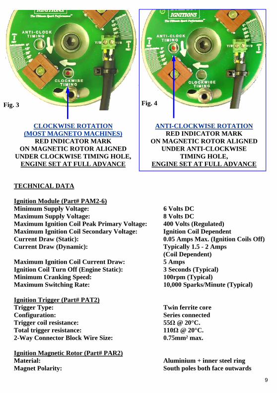
11. Slacken the centre bolt (¼” UNF) using a 3/16” hex key and position the rotor until one of the red indicator marks can be seen through the appropriate static timing hole in the trigger plate (clockwise for most machines), with the plate positioned midway on its adjustment slots. See figs. 3/4 on page 9. [The magnetic rotor centre thread (metric M8) is provided for attaching a puller, if the rotor should need to be removed for engine servicing, etc.]
12. Tighten the magnetic rotor bolt using a 3/16” hex key. 13. Taking the ignition trigger assembly, insert a small cable tie into the two
holes in front of the connector block on the ignition trigger (the tie-strap may have been pre-fitted by your dealer). This will be used later to secure the two wires to the plate.
14. Refit the ignition trigger plate and pillar fixings & washers, positioned approximately in the centre of the slots (to allow for adjustment in either direction). Recheck that the red mark is visible through the appropriate static timing hole (move the plate slightly, if necessary). Handle the trigger with care. Tighten the pillar fixings; do not overtighten or the plate may become distorted.
4
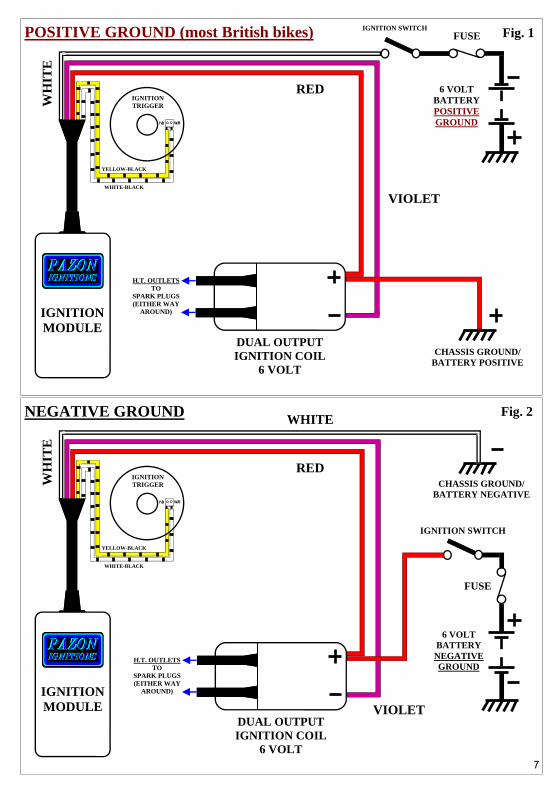
WIRING: 15. All connections must be of the highest quality, use crimped or soldered connections; twisted wires will not give a satisfactory operation. Avoid coiling up surplus lead. 16. Take the VIOLET wire from the ignition module, cut to length and fit an
insulator and female spade connector to the end. Connect to the negative (-) terminal on the ignition coil (marked on the end of the coil with a “—” between the spade terminal and the coil mounting bar). See figs.1/2 on page 7.
17. Take the RED wire from the ignition module, cut to length and fit an insulator and female piggyback connector to the end (marked on the end of the coil with a “+” between the spade terminal and the coil mounting bar). Connect to the positive (+) terminal on the ignition coil. See figs.1/2 on page 7.
18. For NEGATIVE EARTH electrics, go to step 21. 19. For POSITIVE EARTH electrics (standard): Take the WHITE wire from the module, cut to length and fit an insulator and male spade connector to the end. Connect to the ignition switch. 20. Take the RED EARTHING WIRE, fit the female spade connector end to the positive (+) terminal on the ignition coil, using the spare connector on the piggyback terminal (fitted in step 17). Cut to length and fit a ring terminal on the other end and connect to a good earth point on the frame, ideally the battery positive (+) terminal. See fig.1 GOTO STEP 23. 21. For NEGATIVE EARTH electrics: Connect the positive (+) side of the ignition coil to the ignition switch (using the spare connector on the piggyback terminal). This terminal also has the red wire from the ignition module connected to it. See fig.2 22. Take the WHITE wire from the module, cut to length and fit a ring
terminal connector to the end. Connect to a good earth point on the frame, ideally the battery negative (—) terminal. See fig.2
23. Allowing a minimum of 50mm/2” of excess wire between the trigger and ignition module, route the white-black & yellow-black wires from the ignition module down to the magneto replacement housing, feed through the grommet in the cap and around to the connector block on the ignition trigger and cut to length. Using tie-straps or tape, secure these wires to the frame, preferably away from other wiring/h.t. leads. Slide a small length of sleeving of the two wires. With a pair of wire strippers/cutters, carefully remove 4-5mm of insulation from the ends of the two wires. Insert the yellow-black wire into the left-hand screw terminal and the white-black wire into the right-hand screw terminal. The connector block terminals are marked on the trigger plate “Y/B” and “W/B”. Tighten the two screws. Secure the wires and sleeving with the cable tie, fitted in
5
step 13. If preferred, the two wires can be soldered directly to the trigger using the two solder pads provided in front of the connector block. It is essential that these two wires are connected the right way around for correct operation of the ignition system. Reversed connections will give very retarded ignition timing. 24. Remove any redundant wires or insulate bare ends. Re-check all
connections are good and tight; any loose crimps should be removed, slightly closed up and refitted, or preferably replaced.
25. Refit spark plugs, tank, fuel lines, battery & seat, as required. 26. Final ignition timing. Start engine and run for 4-5 minutes to warm up. If strobe timing marks are available, use a white light strobe and time the engine to the full advance mark (previously used in step 8) with the engine running up to 4000rpm. If running in, you may strobe time at 3000rpm to the full advance figure less approx. 2°. Stop the engine and adjust the timing by making very small movements of the ignition trigger on its slotted holes; moving the trigger by 1° is equivalent to 2° of the crankshaft. When using a strobe light, you may see a small amount of advance above 4000rpm, this is normal. To advance the timing, turn the trigger against the direction of the magnetic rotor (normally anti- clockwise). To retard the timing, turn the trigger in the same direction as the magnetic rotor (normally clockwise). In the unlikely event that the timing cannot be obtained before the end of the adjustment slots, the magnetic rotor will need to be slackened off and repositioned slightly. If strobe timing marks are not available, road test the machine and make any final timing adjustments (if necessary) for optimum performance. See advance graph on page 8 (degree figures are based on the full advance settings in table 1. 27. Refit magneto replacement cap. The timing is now set and requires no further adjustment. However, please note that for satisfactory operation of this ignition system it is important that the wiring, ignition coil, switch, battery, h.t. leads, plugs and plug caps are in good order.
6
NEGATIVE GROUND
IGNITION SWITCH
WHITE-BLACK
YELLOW-BLACK
IGNITION TRIGGER
RED
VIOLET
WH
ITE
IGNITION MODULE
CHASSIS GROUND/BATTERY NEGATIVE
FUSE
6 VOLT BATTERY NEGATIVE GROUND
WHITE
W/B Y/B
POSITIVE GROUND (most British bikes)
W/B
6 VOLT BATTERY POSITIVE GROUND
FUSE IGNITION SWITCH
WHITE-BLACK
YELLOW-BLACK
IGNITION TRIGGER
Y/B
RED
VIOLET
WH
ITE
IGNITION MODULE
CHASSIS GROUND/BATTERY POSITIVE
Fig. 1
Fig. 2
DUAL OUTPUT IGNITION COIL
6 VOLT
H.T. OUTLETS TO
SPARK PLUGS (EITHER WAY
AROUND)
DUAL OUTPUT IGNITION COIL
6 VOLT
H.T. OUTLETS TO
SPARK PLUGS (EITHER WAY
AROUND)
7
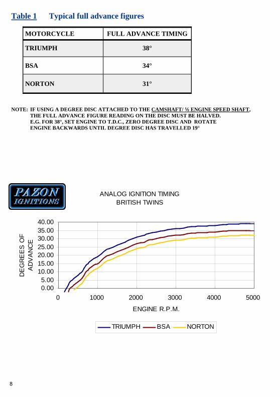
Table 1 Typical full advance figures
NOTE: IF USING A DEGREE DISC ATTACHED TO THE CAMSHAFT/ ½ ENGINE SPEED SHAFT, THE FULL ADVANCE FIGURE READING ON THE DISC MUST BE HALVED. E.G. FOR 38°, SET ENGINE TO T.D.C., ZERO DEGREE DISC AND ROTATE ENGINE BACKWARDS UNTIL DEGREE DISC HAS TRAVELLED 19°
MOTORCYCLE FULL ADVANCE TIMING
TRIUMPH 38°
BSA 34°
NORTON 31°
ANALOG IGNITION TIMINGBRITISH TWINS
0.005.00
10.0015.0020.0025.0030.0035.0040.00
0 1000 2000 3000 4000 5000
ENGINE R.P.M.
DE
GR
EE
S O
F A
DV
AN
CE
TRIUMPH BSA NORTON
8
TECHNICAL DATA Ignition Module (Part# PAM2-6) Minimum Supply Voltage: 6 Volts DC Maximum Supply Voltage: 8 Volts DC Maximum Ignition Coil Peak Primary Voltage: 400 Volts (Regulated) Maximum Ignition Coil Secondary Voltage: Ignition Coil Dependent Current Draw (Static): 0.05 Amps Max. (Ignition Coils Off) Current Draw (Dynamic): Typically 1.5 - 2 Amps (Coil Dependent) Maximum Ignition Coil Current Draw: 5 Amps Ignition Coil Turn Off (Engine Static): 3 Seconds (Typical) Minimum Cranking Speed: 100rpm (Typical) Maximum Switching Rate: 10,000 Sparks/Minute (Typical) Ignition Trigger (Part# PAT2) Trigger Type: Twin ferrite core Configuration: Series connected Trigger coil resistance: 55Ω @ 20°C. Total trigger resistance: 110Ω @ 20°C. 2-Way Connector Block Wire Size: 0.75mm² max. Ignition Magnetic Rotor (Part# PAR2) Material: Aluminium + inner steel ring Magnet Polarity: South poles both face outwards
CLOCKWISE ROTATION (MOST MAGNETO MACHINES)
RED INDICATOR MARK ON MAGNETIC ROTOR ALIGNED
UNDER CLOCKWISE TIMING HOLE, ENGINE SET AT FULL ADVANCE
ANTI-CLOCKWISE ROTATION RED INDICATOR MARK
ON MAGNETIC ROTOR ALIGNED UNDER ANTI-CLOCKWISE
TIMING HOLE, ENGINE SET AT FULL ADVANCE
Fig. 3 Fig. 4
9
Ignition Coils For best results with this system, use an ignition coil with a primary resistance of 1.5 to 2.5ohms, e.g. PAZON part# IC03, as supplied with this system. CDI type and some electronic ignition coils are incompatible with this system; for suitability check the primary resistance is 1.5 ohms or more (measure across the + and — terminals with a multimeter). Alternatively, two single output ignition coils can be used (either 6 volt or preferably 3 volt, if available). When using two ignition coils they must be connected in series (link between the coils from + to —), do not connect the coils in parallel. For a twin-plug head use two dual output coils connected in series with a total primary resistance of between 1.5 to 2.5ohms. General Data/Troubleshooting This system can be adapted to work on many types of engine, provided that the required firing interval is every 360° crankshaft / 180° camshaft. This ignition is of the wasted spark type, i.e. sparking occurs every turn of the engine (on compression & exhaust strokes). Wiring should be cut to the correct length. Excess wire should not be coiled up; this can affect the correct running of the ignition system. Where possible the wires from the ignition trigger should be run separately from the rest of the wiring loom, especially the alternator stator wiring. The frame/chassis must act as an electrical return (ground/earth), whether positive or negative earth. If the engine is rubber mounted a good ground/earth strap must be provided. This system can be run total-loss from a battery only (e.g. for off-road applications). The ignition module features a simple self-test facility for producing sparks without turning the engine. Disconnect the ignition trigger wires (w-b & y-b) from the trigger in the magneto replacement housing. Switch the ignition on. Take the trigger wires and touch the bare ends of the wires together and open them approximately once per second, both plugs should spark at the same time. If there are no sparks, check coil, leads, caps, plugs ,battery, switch, earthing, wiring, connections & ignition module. Continuous sparks without turning the engine indicates a poor supply to the ignition; check battery (bad cell), switch, earthing and electrical connections.
10
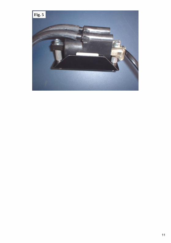
Fig. 5
11
PAZON, PO BOX 405, SITTINGBOURNE, KENT ME9 9WJ U.K. TELEPHONE: 08700 114858 FAX: 08700 119868
EMAIL: [email protected] WEB: www.pazon.com PAMT1-6
Terms & Conditions and Warranty • Use of this product indicates your acceptance of this notice. • The product design & literature is Copyright © PAZON 2005, & is protected under
international copyright, trademark & treaty provisions. • To provide the best ignition systems possible, PAZON IGNITIONS reserves the right to
alter & improve the specifications of its products without prior notice.
Ignition Systems • Pazon warrants to the original purchaser that the Pazon Ignition System be free from defects
in workmanship & parts under normal use for a period of five years from date of purchase. Ignition Spares • Spares are defined as item(s) not purchased as part of a complete ignition system. Pazon
warrants to the original purchaser that these item(s) be free from defects in workmanship & parts under normal use for a period of one year from date of purchase.
• Ignition coils will only be covered by the warranty if it can be proved that the fault is due to a manufacturing fault within the coil.
Limitation of Liability • In no event shall Pazon's liability related to the product exceed the purchase price actually
paid for the product. • Neither PAZON nor its suppliers shall in any event be liable for any damages whatsoever
arising out of or related to the use or inability to use the product, including but not limited to the direct, indirect, special, incidental or consequential damages, or other pecuniary loss.
• This warranty will be void if the product or parts have been altered, damaged, abused or installed incorrectly.
• This warranty will be void if parts supplied by Pazon are used with other makes of ignition. Your statutory rights are not affected.
Warranty Claims • To make a claim under warranty, the product must be returned to PAZON or its authorized
representative, with a copy of your receipt (or evidence of date & place of purchase), within the warranty period.
• Include a detailed description of the problem and why you believe there is a fault within the ignition system.
• The system must be returned postage paid. Proof of posting is not proof or receipt, therefore we recommend using a recorded mail service.
• Upon receipt we will thoroughly test the returned items and repair or replace any items found to be faulty and covered by the warranty.
• Please allow seven working days from receipt of the returned parts before contacting us, to allow sufficient time for a thorough test and evaluation.
• PLEASE CONTACT PAZON IGNITIONS FOR RETURN INSTRUCTIONS.
12