Embed Size (px)
Citation preview

0679
Büro für Tragwerksplanung und Ingenieurbau
Dipl.-Ing. Ralf-Harald vom Felde
Lütticher Straße 10-12 Telefon: 0241 / 70 96 9652064 Aachen Telefax: 0241 / 70 96 46
Structural Report GeoS12-Serie
for the system of
Nexo S.A.154 Allée des Erables
F 95950 Roissy CDG Cedex
Aachen, 27th March 2008
This structural analysis includes pages 1 - 61

Büro für Tragwerksplanung und Ingenieurbau Lütticher Straße 10-12 Telefon: 0241 / 70 96 96 52064 Aachen Telefax: 0241 / 70 96 46 Dipl.-Ing. Ralf-Harald vom Felde [email protected]
1
TABLE OF CONTENTS
TABLE OF CONTENTS . . . . . . . . . . . . . . . . . . . . . . . . . . . . . . . . . . . . . . . . . . . . . . . 1
1 PRELIMINARY NOTES . . . . . . . . . . . . . . . . . . . . . . . . . . . . . . . . . . . . . . . . . . . . . . 2
1.1 Technical Bases . . . . . . . . . . . . . . . . . . . . . . . . . . . . . . . . . . . . . . . . . . . . 21.2 Applied Building Materials . . . . . . . . . . . . . . . . . . . . . . . . . . . . . . . . . . . . . 21.3 General Description . . . . . . . . . . . . . . . . . . . . . . . . . . . . . . . . . . . . . . . . . 21.4 Restrictions concerning maximum number of cabinets . . . . . . . . . . . . . . 31.5 Loading and safety level . . . . . . . . . . . . . . . . . . . . . . . . . . . . . . . . . . . . . 4
2 SYSTEM COMPONENTS AND ASSEMBLY . . . . . . . . . . . . . . . . . . . . . . . . . . . . . 6
3 GEOS-12/30 ARRAY - Touring . . . . . . . . . . . . . . . . . . . . . . . . . . . . . . . . . . . . . . . . 8
3.1 System overview . . . . . . . . . . . . . . . . . . . . . . . . . . . . . . . . . . . . . . . . . . . . 83.2 Center of gravity . . . . . . . . . . . . . . . . . . . . . . . . . . . . . . . . . . 93.3 Internal Forces . . . . . . . . . . . . . . . . . . . . . . . . . . . . . . . . . . . . . . . . . . . . 103.4 Allowable Loading . . . . . . . . . . . . . . . . . . . . . . . . . . . . . . . . . . . . . . . . . 13
4 GEOS12/30-ARRAY Fixed-Installation . . . . . . . . . . . . . . . . . . . . . . . . . . . . . . . . 24
4.1 System overview . . . . . . . . . . . . . . . . . . . . . . . . . . . . . . . . . . . . . . . . . . . 244.2 Gravity center . . . . . . . . . . . . . . . . . . . . . . . . . . . . . . . . . . . . . . . . . . . . . 254.3 Internalforce . . . . . . . . . . . . . . . . . . . . . . . . . . . . . . . . . . . . . . . . . . . . . . 254.4 Allowable loading . . . . . . . . . . . . . . . . . . . . . . . . . . . . . . . . . . . . . . . . . . 28
5 TOURING ACCESSORIES . . . . . . . . . . . . . . . . . . . . . . . . . . . . . . . . . . . . . . . . . . 33
5.1 TCBRK-V2 . . . . . . . . . . . . . . . . . . . . . . . . . . . . . . . . . . . . . . . . . . . . . . . 335.2 TTC-V2 . . . . . . . . . . . . . . . . . . . . . . . . . . . . . . . . . . . . . . . . 345.3 LYRE-V2 . . . . . . . . . . . . . . . . . . . . . . . . . . . . . . . . . . . . . . . . . . . . . . . . . 355.4 SSBRK-V2 . . . . . . . . . . . . . . . . . . . . . . . . . . . . . . . . . . . . . . . . . . . . . . . 375.5 PSBRK-V2 . . . . . . . . . . . . . . . . . . . . . . . . . . . . . . . . . . . . . . . . . . . . . . . 385.6 XHBRK . . . . . . . . . . . . . . . . . . . . . . . . . . . . . . . . . . . . . . . . . . . . . . . . . . 39
6 FIXED INSTALLATION ACCESSORIES . . . . . . . . . . . . . . . . . . . . . . . . . . . . . . . . 40
6.1 UBRK . . . . . . . . . . . . . . . . . . . . . . . . . . . . . . . . . . . . . . . . 406.2 LBRK . . . . . . . . . . . . . . . . . . . . . . . . . . . . . . . . . . . . . . . . . . . . . . . . . . . . 426.3 ABRK . . . . . . . . . . . . . . . . . . . . . . . . . . . . . . . . . . . . . . . . . . . . . . . . . . . . 44
7 GROUNDSTACK MODE . . . . . . . . . . . . . . . . . . . . . . . . . . . . . . . . . . . . . . . . . . . . 45
7.1 Proof of stability . . . . . . . . . . . . . . . . . . . . . . . . . . . . . . . . . . . . . . . . . . . . 457.2 Strcutural integrity of rigging parts . . . . . . . . . . . . . . . . . . . . . . . . . . . 52
8 RIGGING SYSTEM RS15 . . . . . . . . . . . . . . . . . . . . . . . . . . . . . . . . . . . . . . . . . . . . 57

Büro für Tragwerksplanung und Ingenieurbau Lütticher Straße 10-12 Telefon: 0241 / 70 96 96 52064 Aachen Telefax: 0241 / 70 96 46 Dipl.-Ing. Ralf-Harald vom Felde [email protected]
2
1 PRELIMINARY NOTES
1.1 Technical Bases
DIN 1055 Design Loads for BuildingsDIN 4112 Temporary structuresDIN 18 800, Steel structures; design and constructionDIN 3065 Steel wires ropesUser Manuals GeoS-12 Series, RS15 Series
1.2 Applied Building Materials
Steel IMEX 701 (S700 acc. to NF EN 10149-2)S 235 JR
Bolts Ballock pins stainless steel 1.4305 fyk / fuk = 300 / 620Socket Head Shoulder srew 12.9 fyk / fuk = 1080 / 1200 N/mm²Bolt Inox 304 L fyk / fuk = 500 / 630 N/mm²Srews A70 fyk / fuk = 450 / 700 N/mm²Standard bolts and srews in classe 4.6 , 10.9 , 12.9
Wood Baltic Birch Ply
1.3 General Description
Subject of this structural calculation is the GeoS12 Tangent Array and the RS15subwoofer assembly system developed by the Nexo company.
The GeoS12 Tangent Array has been designed for the deployment of curved vertical,horizontal and groundstacked arrays of GeoS12-10 and GeoS12-30 loudspeakers. There are two kinds of rigging-system. One has been developped for touring-applicationsand the other for fixed installations.
Ther riggingsystem of the GeoS loudspeakers is a bending resistant system and consists of steel elements which are fixed on two sides of a loudspeaker and connectedover 4 locking pins with the appropriate steel elements of the neighbouring cabinet. The system is designed to enable different angle settings between adjacent cabinets.The maximum angle between two cabinets is limited to 10° (GeoS12/10) resp 30°(GeoS12/30). The cluster system can be flown for the touring applictaion with onehanging point. For fixe installations the top-bumpoer is fixed by 4 screws to asubstructure or cable mounted with accessories. The substructure is not part of thisreport.
Additional to the cluster system this report contains the proof of several accessories fortouring and fixed installation apllications.
Restrictions concerning the maximum number of cabinets which can be flowntogether or used in combination with the accesories see next page.
The RS15 system can be used for an vertical hanging subwoofer-cluster. The riggingsystem consits of 4 vertical riggings parts which are placed at the four corners of thecabinet. The maximum number is limited to 16 RS15.
This structural report takes as condition that all safety requirements in the UserManuals - GeoS12 Series - and -RS15 series- are respected.

Büro für Tragwerksplanung und Ingenieurbau Lütticher Straße 10-12 Telefon: 0241 / 70 96 96 52064 Aachen Telefax: 0241 / 70 96 46 Dipl.-Ing. Ralf-Harald vom Felde [email protected]
3
1.4 Restrictions concerning maximum number of cabinets
GeoS12-Cluster
For all desired configurations an individuel proof of structural integrity likedescibed in this report is necessary. It is not sufficient to respect only themaximum allowable number of cabinets. Especially angle seetings with importantangles between the cabinets can reduce the maximum allowable number of cabinetswhich can be flown together.
For practical use the proof of structural integrity like described in this report has beenintroduced in the programme GeoSoft.
GeoS12- cluster Touring max. 12 GeoS12
The linkbarVersion TLB can be used without any restrictions for flown touring-cluster intension mode.
GeoS12-cluster Fixed Max Number depends on theconfiguration and allowable loading ofthe substructure.
Accessories GeoS12
Touring
TCBRK-V2 2 GeoS12
TTC-V2 1 GeoS12
LYRE-V2 in combination with SSBRK-V2 1 GeoS12
LYRE-V2 in combination with PSBRK-V2 2 GeoS12
XHBRK 4 GeoS12 per XHBRK
Fixed installation
UBRK 1 GeoS12
LBRK in horizontal mode, cable mounted 3 GeoS12 per LBRK
2 LBRK with F-Bumper, cable mounted Cluster with max 10 GeoS12
ABRK in horizontal mode, 4 GeoS12 per ABRK
Groundstack-Mode GeoS12
base angel between -10° and 10° 6 GeoS12 maximum angle setting 10° between two cabinets
RS15 - cluster max 16 RS15
Büro für Tragwerksplanung und Ingenieurbau Lütticher Straße 10-12 Telefon: 0241 / 70 96 96 52064 Aachen Telefax: 0241 / 70 96 46 Dipl.-Ing. Ralf-Harald vom Felde [email protected]
4
1.5 Loading and safety level
Wind forces for touring apllictaions are applied according to DIN 1055, Part 5, (1986), andDIN 4112 (1983).
According to DIN 4112 the impact pressure can be reduced if the service of the system isstopped at wind force greater beaufort 8 (resp. v = 20,7m/s). In this case the impactpressure can be set as follows
For 0 ÷ 5,00 m over ground q = 0,15 kN/m²For h > 5,00 m over ground q = 0,25 kN/m²
For wind lower than beaufort 8 the impact pressure can be reduced dependent on thewindspeed:
In case of wind lower beaufort 6 (v = 13,8 m/s)
For h > 5,00 m over ground q = 13,8² / 20,7² · 0,25 = 0,12 kN/m²
Snow loads are not taken into account because they are very low in relation to the otherloads.
For fixed installations windloading has to be taken into account in accordance to the nationalstandards.
Selfweight elements GeoS12 Array
Loudspeaker GeoS12/10 including Rigging-parts Gi = 33 kgLoudspeaker GeoS12/30 including Rigging-parts Gi = 32 kg
Touring Bumper G = 20 kg
Selfweight elements RS15 Array
Subwoofer RS15 including Rigging-parts Gi = 65 kgTouring Bumper G < 60 kg

Büro für Tragwerksplanung und Ingenieurbau Lütticher Straße 10-12 Telefon: 0241 / 70 96 96 52064 Aachen Telefax: 0241 / 70 96 46 Dipl.-Ing. Ralf-Harald vom Felde [email protected]
5
Safety level
To cover dynamic effects during lifting the assemblies and faults made during rigging thesafety level concerning loading is set to 4.
This safety factor includes a safety factor of 1,5 acc. to DIN 1055-100By exmaple incombination with DIN18800
a safety factor of 2,0 acc. to the European Machinery Directive
a dynamic factor of 1,3
Summary 1,5 · 2,0 · 1,3 = 3,9 < 4,0
The safety level concerning resistance of the steel-components is set according toDIN 18800 Part 1 to 1,1.
In combination with material-standards which are not based on a semi probalistic safetysystem the safety factor of 1,5 acc. to DIN 1055-100 must not be taken into account (This safety factor is then allready taken into account in the material specific safetysystem)
Büro für Tragwerksplanung und Ingenieurbau Lütticher Straße 10-12 Telefon: 0241 / 70 96 96 52064 Aachen Telefax: 0241 / 70 96 46 Dipl.-Ing. Ralf-Harald vom Felde [email protected]
6
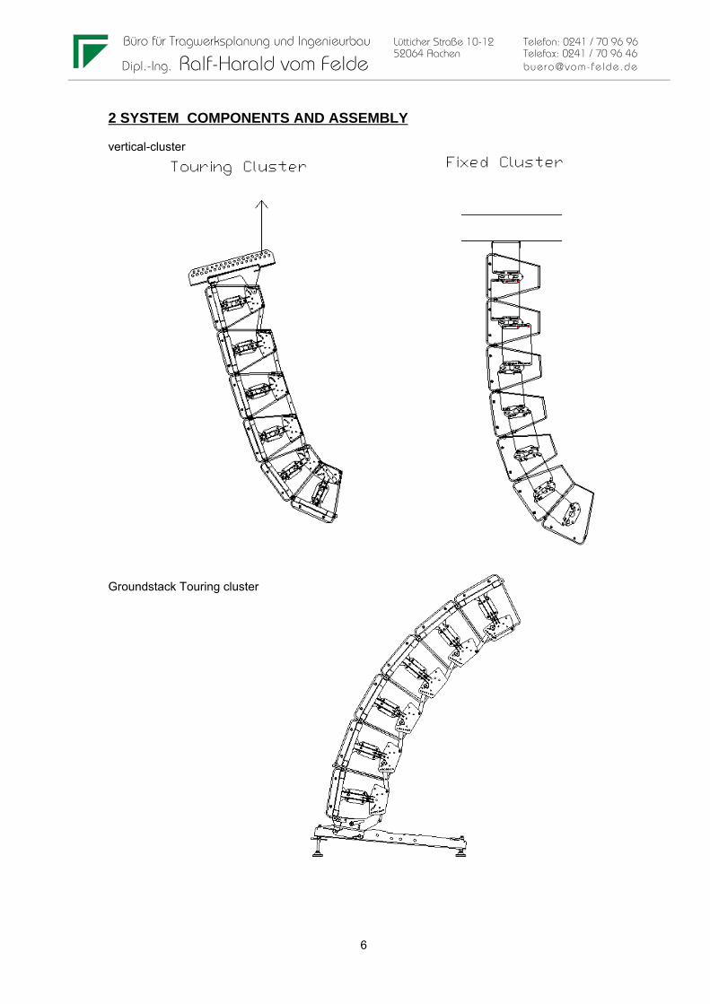
2 SYSTEM COMPONENTS AND ASSEMBLY
vertical-cluster
Groundstack Touring cluster

Büro für Tragwerksplanung und Ingenieurbau Lütticher Straße 10-12 Telefon: 0241 / 70 96 96 52064 Aachen Telefax: 0241 / 70 96 46 Dipl.-Ing. Ralf-Harald vom Felde [email protected]
7
Accessories Fixed installations
Accessories touring applictaions

Büro für Tragwerksplanung und Ingenieurbau Lütticher Straße 10-12 Telefon: 0241 / 70 96 96 52064 Aachen Telefax: 0241 / 70 96 46 Dipl.-Ing. Ralf-Harald vom Felde [email protected]
8
3 GEOS-12/30 ARRAY - Touring
3.1 System overview
Reference-point and local gravity center

Büro für Tragwerksplanung und Ingenieurbau Lütticher Straße 10-12 Telefon: 0241 / 70 96 96 52064 Aachen Telefax: 0241 / 70 96 46 Dipl.-Ing. Ralf-Harald vom Felde [email protected]
9
3.2 Center of gravity
The center of gravity of a cluster is calculated by:
Ys =( 3Gi· ysi ) / 3Gi Xs =( 3Gi· xsi ) / 3Gi
with Gi = 0,33 kN weight of loudspeakersGB = 0,20 kN weight of bumper
ysi,xsi = coordinates of gravity center of a loudspeaker / bumper reffering to the base point Y/X = 0/0
The coordinates from the gravity center of the top bumper reffering to the base point iscalcualted by
ysi = ex· sinΨo + ey · cos Ψoxsi = ex· cosΨo - ey · sin Ψo
with ex = -0,056 m ey = 0,175 m
The coordinates from the gravity center of a loudspeaker reffering to the base point iscalculated by
ysi = yi +ex· sinΨi + ey · cos Ψixsi = xi +ex· cosΨi - ey · sin Ψi
with ex = 0,1725m ey = 0,122m
and yi,xi = global coordinates of the front connection point of a loudspeaker
at first box yi = xi =0for all following boxes yi = yi-1 + hH,i-1
xi = xi-1 + hV,i-1

Büro für Tragwerksplanung und Ingenieurbau Lütticher Straße 10-12 Telefon: 0241 / 70 96 96 52064 Aachen Telefax: 0241 / 70 96 46 Dipl.-Ing. Ralf-Harald vom Felde [email protected]
10
3.3 Internal Forces
3.3.1 General remarks
For the calculation the following notation is used:
n number of boxesi position of a box i=1 first box at the top
i=n last box
Ψi horizontal angle of a box in postion i Ψo horizontal angle of top bumper
hi height of a box = 0,345m
hH,i horizontal projection of the height hi hH,i = hi · sin ΨihV,i vertical projection of the height hi hV,i = hi · cos Ψi
hhp total horizontal projection of the clusterhvp total verticla projection of the cluster
G total weight of the cluster = 3 GiGi selfweight of a loudspeaker
Wi resultant wind load on a box
FVi internal global vertical force between boxes at position i and i-1FHi internal global horizontal force between boxes at position i and i-1Mi internal moment between the boxs at position i and i-1
FIIi internal local force parallel to the front sideFLi internal local force rectangular to the front side

Büro für Tragwerksplanung und Ingenieurbau Lütticher Straße 10-12 Telefon: 0241 / 70 96 96 52064 Aachen Telefax: 0241 / 70 96 46 Dipl.-Ing. Ralf-Harald vom Felde [email protected]
11
3.3.2 Internal forces at reference point
The internal forces are calculated allong a curved beam which is defined by the front connectionpoints of the rigging system.
The calculation has to start at the lowest position (Loudspeaker with index n):
Fvn = Gn + Wn · sin Ψn
Fhn = Wn · cos Ψi - FB
Mi = Gn ·( ex · sinΨn + ey · cosΨn) + Wn · hn / 2 - FB · hv,i
with ex = 0,1725m ey = 0,122m
and FB = w · Hv / 2 Bracingforce in case of Wind Bracing
Hv = total vertical projection of the cluster
w = windloading as distrbuted load [kN/m]
For all following loudspeakers i > n
Fvi = Fvi+1 + Gi + Wi · sin Ψi
Fhi = Fhi+1 + Wi · cos Ψi
Mi = Mi+1 + (Fhi+1 ·cosΨi + Fvi+1· sinΨi ) · hi + Gi ·( ex · sinΨi + ey · cosΨi) + Wi · hi / 2
Transformation of FV and FH into local direction
FIIi = FVi · cos Ψi - FHi · sin ΨiFLi = FVi · sin Ψi + FHi · cos Ψi

Büro für Tragwerksplanung und Ingenieurbau Lütticher Straße 10-12 Telefon: 0241 / 70 96 96 52064 Aachen Telefax: 0241 / 70 96 46 Dipl.-Ing. Ralf-Harald vom Felde [email protected]
12
3.3.3 Transformation into local forces at connection points
The forces S1 and S2 are depending on the angle-setting of the link-bar. For the proof of structural integrity two extreme cases are taken into account
1. S2 inclined by 24° ( Link bar on 0,2° position)2. S2 inclined by 0° ( Linkbar on 5° position)3. S2 inclined by 0° (connection to bumper)
Case 1 S2 inclined by 24° - Link bar on 0,2° position
S2 = Mi / (2 · 0,251)
S1V = FIIi / 2 - S2· cos 24°
S1H= FLi / 2 - S2· sin 24°
Case 2 S2 inclined by 0° - Linkbar on 5° position
S2 = Mi / (2·0,316)
S1V = FIIi / 2 - S2
S1H= FLi / 2
Case 3 S2 inclined by 0° - connection to bumper
S2 = Mi / (2·0,288)
S1V = FIIi / 2 - S2
S1H= FLi / 2

Büro für Tragwerksplanung und Ingenieurbau Lütticher Straße 10-12 Telefon: 0241 / 70 96 96 52064 Aachen Telefax: 0241 / 70 96 46 Dipl.-Ing. Ralf-Harald vom Felde [email protected]
13
3.4 Allowable Loading
3.4.1 X-BOW V2 Rigging-System
Front connection
by 8mm Ball-lock 1.4305 Nirosta
Shearing acc. to DIN 50141
V = 38 kN
Tear out
e1 = e2 = 15,75 mm = 1,92 · dL
=> a = 1,81
Vlrd = t · dL · a · fyk / 1,1
Vlrd = 2 · 0,3·0,8 ·1,81 · 70 / 1,1 = 55,3 kN
Summary
=> allowable Loading S [kN] including safety factor =4
S < 38 / 4 = 9,5 kN

Büro für Tragwerksplanung und Ingenieurbau Lütticher Straße 10-12 Telefon: 0241 / 70 96 96 52064 Aachen Telefax: 0241 / 70 96 46 Dipl.-Ing. Ralf-Harald vom Felde [email protected]
14
Link bar - standard and Version TLB
Link-bar Version TLB only for flown clusters (in tensions mode)
Tear out at Link bar
e1 = e2 = 14 mm = 1,71 · dL
=> a = 1,58
Vlrd = t · dL · a · fyk / 1,1
Vlrd = 0,6·0,8 ·1,58 · 70 / 1,1 = 48,26 kN
connection to X-Bow
by 8mm Ball-lock 1.4305 Nirosta
Shearing acc. to DIN 50141 V = 38 kN
and Socket Head Shoulder screw M6D8 12.9
Calculation for srew 10.9
Shearing acc. to DIN 18800 T1
Va,rd =2 · 0,50cm² · 0,44 · 100 /1,1 = 40 kN
=> allowable Loading S [kN] including safety factor =4
S < 38 / 4 = 9,5 kN
Buckling under pressure forces(only for standard Link-bar in Groundstack-mode)
sk = 19,7-0,82= 18,9 cm i = 0,289 · 0,6 = 0,173 cm
λ = 18,9 / 0,173 = 109λa = π (210000 / 700)0,5 = 54,4λ*= 109/ 54,4 = 2,01
=> k = 0,195 acc. to DIN 18800
=> Vrd = 0,195 · 2,8·0,6 · 70 /1,1 = 20,85 kN
=> allowable Loading S [kN] including safety factor =4
S = 20,85 / 4 = 5,21 kN (only relevant for pressure forces)

Büro für Tragwerksplanung und Ingenieurbau Lütticher Straße 10-12 Telefon: 0241 / 70 96 96 52064 Aachen Telefax: 0241 / 70 96 46 Dipl.-Ing. Ralf-Harald vom Felde [email protected]
15
Tear out at Rigging-Plate (Position for 0,2° angle setting is relevant)
e1 > 14 mm = 1,71 · dL
e2 = 10 mm = 1,22 ·dL
=> a = 1,08
Vlrd = t · dL · a · fyk / 1,1
Vlrd = 0,6·0,8 ·1,08 · 70 / 1,1 = 30,54 kN
=> allowable Loading S [kN] including safetyfactor =4
S < 30,54 / 4 = 7,64 kN
Summary allowable Loading S [kN] including safety factor =4
under tension forces: all S = 7,64 kN
under pressure forces all S = -5,21 kN only for standard link-bar

Büro für Tragwerksplanung und Ingenieurbau Lütticher Straße 10-12 Telefon: 0241 / 70 96 96 52064 Aachen Telefax: 0241 / 70 96 46 Dipl.-Ing. Ralf-Harald vom Felde [email protected]
16
Bending in X-Bow
To cover all theoretic possible combination of internal forces by conditions as simple aspossible the limits for the internal forces S1v, S1h and S2 are set as follows.
-5,0 kN < S2 < 5,0 kN
-5,0 kN < S1v < 5,0 kN
-2,0 kN < S1h < 2,0 kN

Büro für Tragwerksplanung und Ingenieurbau Lütticher Straße 10-12 Telefon: 0241 / 70 96 96 52064 Aachen Telefax: 0241 / 70 96 46 Dipl.-Ing. Ralf-Harald vom Felde [email protected]
17
Cross-Section
h 4,30 [cm]b 3,60 [cm]th 0,30 [cm]tb 0,30 [cm]
dl 0,00 [cm]e1 0,00 [cm]
h' 4,00 [cm]b' 3,45 [cm]
Wy 4,60 [cm³]A 3,27 [cm²] Wz-1 3,47 [cm³]
ys 1,09 [cm] Wz-2 1,83 [cm³]Iyy 9,88 [cm4]Izz 4,31 [cm4] (W-pl=2xS)Sy 2,67 [cm³] Wy-pl 5,34 [cm³]Sz 1,67 [cm³] Wz-pl 3,34 [cm³]
b
h
t = const.
ysdL
e1
Front - bar U 43x36x3 mm
Maximum bending Moment in Front-bar limited by S1h to
Mmax = 2,0 kN · 17,25 cm = 34,5 kNcm
Maximum Normalforces in Front-bar limited by S1v to
Nmax = 5,0 kN
Stresses
allowable Stress Imex700 including safety acc. to DIN 18800
fyk = 70 / 1,1 = 63,63 kN/cm²
Verification of stress including safety factor of 4
4 ·(5,0kN / 3,27 cm² + 34,5 kNcm / 3,34 cm³) = 47,44 kN/cm² < 63,63

Büro für Tragwerksplanung und Ingenieurbau Lütticher Straße 10-12 Telefon: 0241 / 70 96 96 52064 Aachen Telefax: 0241 / 70 96 46 Dipl.-Ing. Ralf-Harald vom Felde [email protected]
18
Cross-Section
h 4,00 [cm]b 3,60 [cm]th 0,30 [cm]tb 0,30 [cm]
dl 0,00 [cm]e1 0,00 [cm]
h' 3,70 [cm]b' 3,45 [cm]
Wy 4,18 [cm³]A 3,18 [cm²] Wz-1 3,30 [cm³]
ys 1,12 [cm] Wz-2 1,81 [cm³]Iyy 8,35 [cm4]Izz 4,20 [cm4] (W-pl=2xS)Sy 2,43 [cm³] Wy-pl 4,86 [cm³]Sz 1,62 [cm³] Wz-pl 3,25 [cm³]
b
h
t = const.
ysdL
e1
Transverse - bar U 40x36x3 mm
For the maximum bending moments in the transverse bar two independent cases can bepossible.
1. Maximum forces S2h => Mmax = 2 · 2,0 · 17,25 = 69 kNcm
2. Maximum forces S2 with maximum lever arm => Mmax = 5,0 · 13,78 = 68,9 kNcm (Both Link-bars on 0,2° position)
In both cases there are no Normal-forces in the transverse bar. Normal froces only appear when one force of the pair is lower then the other and in this case thebending moment is lower => not. relevant
allowable Stress Imex700 including safety acc. to IN 18800
fyk = 70 / 1,1 = 63,63 kN/cm²
Verification of stress including safety factor of 4
4 ·69 kNcm / 4,86 cm³ = 56,79 kN/cm² < 63,63

Büro für Tragwerksplanung und Ingenieurbau Lütticher Straße 10-12 Telefon: 0241 / 70 96 96 52064 Aachen Telefax: 0241 / 70 96 46 Dipl.-Ing. Ralf-Harald vom Felde [email protected]
19
Bumper
internal forces
The internal forces are calculated for a unit force of 10 kN at the hanging point. Three positionsof the hanging point are taken into account.
1.+ 2. Hanging point in extreme left and right poistion
3. Hanging Point in the middle of the central bar
Then on the base of the internal forces due to the unit load of 10 kN the allowable total weigth ofa cluster is calculated.

Bem
LC 1: Load
LC 2: Load

LC 3: Load
Load case combination 10
1. Variable exclusive action Factor
1 1,0002 1,0003 1,000
Internal forces My min, max; K10

Büro für Tragwerksplanung und Ingenieurbau Lütticher Straße 10-12 Telefon: 0241 / 70 96 96 52064 Aachen Telefax: 0241 / 70 96 46 Dipl.-Ing. Ralf-Harald vom Felde [email protected]
22
Section a-a L 50x50x6 mm
Max M = 52 kNcm due to 10 kN
Wel = 3,61 cm³
Allowable stress σ = 0,7* · 70 / 1,1 = 44,55 kN/cm²
* reducing allowable stress to 70% acc. to DIN 18800, because calculation ofstresses are not done for the principle axes of the section
=> allowable maximum Load incl. safety factor of 4
4· P· 52 kNcm / (10 KN ·3,61cm³) < 44,55 kN/cm² => P< 7,73 kN
Section b-b U 50x50x6 mm
Max M = 230 kNcm
Wel = 12,62 cm³
Allowable stress σ = 70 / 1,1 = 63,63 kN/cm²
=> allowable maximum Load incl. safety factor of 4
4· P· 230 / (10·12,62) < 63,63 => P< 8,7 kN
Section c-c and d-d U 60x90x6 resp U 60x117x6
Max M = 104 kNcm
on the safe side the stress calculation is based on the following simplified cross section Tow rectangular corss setions (6x81) with a hole of 41 mm
Iyy = 0,6 · (8,1³ - 4,1³) / 12 = 23,13 cm4
Wel = 23,13 / 4,05 = 5,711
Allow. stress σ = 70 / 1,1 = 63,63
4 · P · 104 / (10· 5,711) < 63,63
=> P < 8,70 kN
Büro für Tragwerksplanung und Ingenieurbau Lütticher Straße 10-12 Telefon: 0241 / 70 96 96 52064 Aachen Telefax: 0241 / 70 96 46 Dipl.-Ing. Ralf-Harald vom Felde [email protected]
23
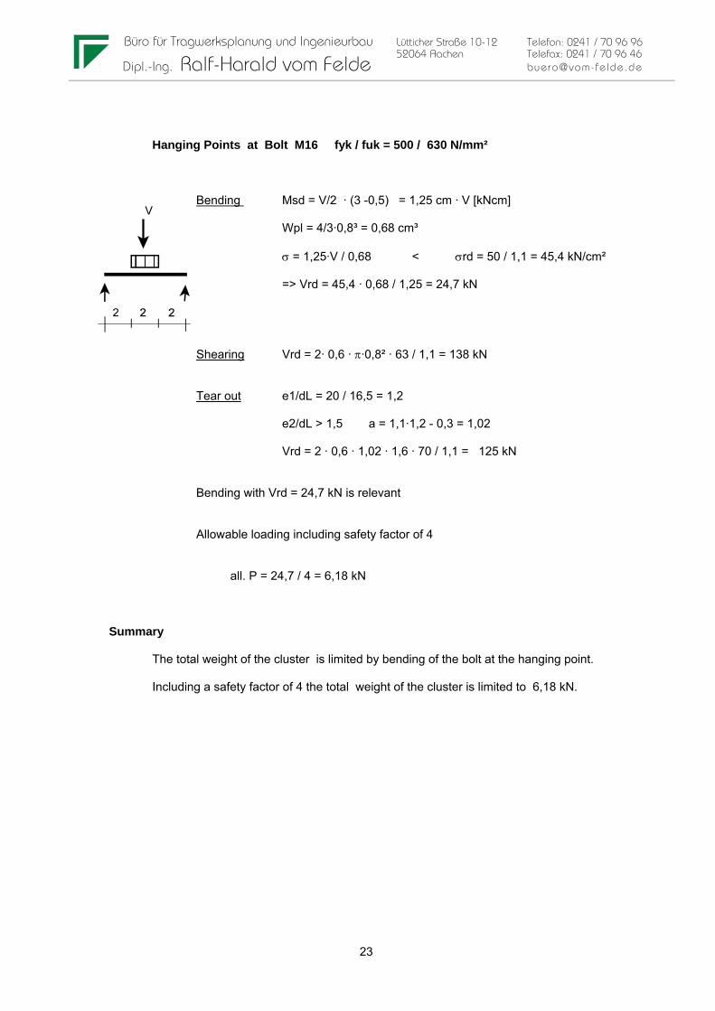
Hanging Points at Bolt M16 fyk / fuk = 500 / 630 N/mm²
Bending Msd = V/2 · (3 -0,5) = 1,25 cm · V [kNcm]
Wpl = 4/3·0,8³ = 0,68 cm³
σ = 1,25·V / 0,68 < σrd = 50 / 1,1 = 45,4 kN/cm²
=> Vrd = 45,4 · 0,68 / 1,25 = 24,7 kN
Shearing Vrd = 2· 0,6 · π·0,8² · 63 / 1,1 = 138 kN
Tear out e1/dL = 20 / 16,5 = 1,2
e2/dL > 1,5 a = 1,1·1,2 - 0,3 = 1,02
Vrd = 2 · 0,6 · 1,02 · 1,6 · 70 / 1,1 = 125 kN
Bending with Vrd = 24,7 kN is relevant
Allowable loading including safety factor of 4
all. P = 24,7 / 4 = 6,18 kN
Summary
The total weight of the cluster is limited by bending of the bolt at the hanging point.
Including a safety factor of 4 the total weight of the cluster is limited to 6,18 kN.

Büro für Tragwerksplanung und Ingenieurbau Lütticher Straße 10-12 Telefon: 0241 / 70 96 96 52064 Aachen Telefax: 0241 / 70 96 46 Dipl.-Ing. Ralf-Harald vom Felde [email protected]
24
4 GEOS12/30-ARRAY Fixed-Installation
4.1 System overview

Büro für Tragwerksplanung und Ingenieurbau Lütticher Straße 10-12 Telefon: 0241 / 70 96 96 52064 Aachen Telefax: 0241 / 70 96 46 Dipl.-Ing. Ralf-Harald vom Felde [email protected]
25
4.2 Gravity center
The calculation of the gravity center is equal to the calculation for the Touring - Cluster(see chapter 3.2)
The weight of a loudspeaker including rigging-parts is 33 kg
The weight of the bumper is about 5 kg.
4.3 Internalforce
4.3.1 General remarks
In a first step the internal forces are calculated analogue to the touring cluster at thereference point. So the calculation of the internal forces till the point of the internal forcesMi, FII,i and FL,i is equal to the calculation for the touring cluster.
Due to the similar way of calculation the same notation as for the touring cluster is used
4.3.2 Internal forces at reference point
Calculation of Mi, FII,i and FL,i see chapter 3.3.2

Büro für Tragwerksplanung und Ingenieurbau Lütticher Straße 10-12 Telefon: 0241 / 70 96 96 52064 Aachen Telefax: 0241 / 70 96 46 Dipl.-Ing. Ralf-Harald vom Felde [email protected]
26
4.3.3 Transformation into local forces at connection points
S2v,i = ( Mi - FII,i · 0,0634 - FL,i · 0,142 ) / (2·0,104)
S1v,i = FII;i / 2 - S2v,i
S1h,i = S2h,i = FL,i / 4

Büro für Tragwerksplanung und Ingenieurbau Lütticher Straße 10-12 Telefon: 0241 / 70 96 96 52064 Aachen Telefax: 0241 / 70 96 46 Dipl.-Ing. Ralf-Harald vom Felde [email protected]
27
4.3.4 Transformation intot local forces at fixation points on top
The forces at the top connection points are calculated from the internal forces at the referncepoint of the first loudspeaker. Two extreme cases are taken into account.
1. Bumper in 0° Postion
F2 = ( M1 + FL,1·0,0945) / (2 · 0,160)
F1 = FII,1 / 2 - F2
F3-h = FL,1 / 2
2. Bumper in 5° Position
F2 = (M1+ FL,1·0,085 - FII,1·0,05) / (2 · 0,160)
F1 = -(M1 + FL,1·0,099 - FII,1·0,209) / (2·0,160)
F3-h = FL / 2 - (F1+F2) ·sin5°

Büro für Tragwerksplanung und Ingenieurbau Lütticher Straße 10-12 Telefon: 0241 / 70 96 96 52064 Aachen Telefax: 0241 / 70 96 46 Dipl.-Ing. Ralf-Harald vom Felde [email protected]
28
4.4 Allowable loading
Rigging- and External Plate
Connection Riggingplate to Externalplate
Conncetion by Socket Head shoulder srew M6D8x20 12.9
Shearing D 8mm A = 0,5 cm³
Materiel 12.9 fub,k = 120 kN/cm²
Shearing acc. to DIN 18800 T1
Va,rd =2 · 0,50cm² · 0,44 · 120 /1,1 = 48 kN
Tear out (external and rigging plate)
DL = 8,2 mm
e1 = 14 mm = 1,71 dL
e2 >= 14 mm > 1,5 dL
=> a = 1,58
Vlrd = t · dL · a · fyk / 1,1
Vlrd = 2 · 0,3·0,8 ·1,58 · 70 / 1,1 = 48,3 kN
Büro für Tragwerksplanung und Ingenieurbau Lütticher Straße 10-12 Telefon: 0241 / 70 96 96 52064 Aachen Telefax: 0241 / 70 96 46 Dipl.-Ing. Ralf-Harald vom Felde [email protected]
29
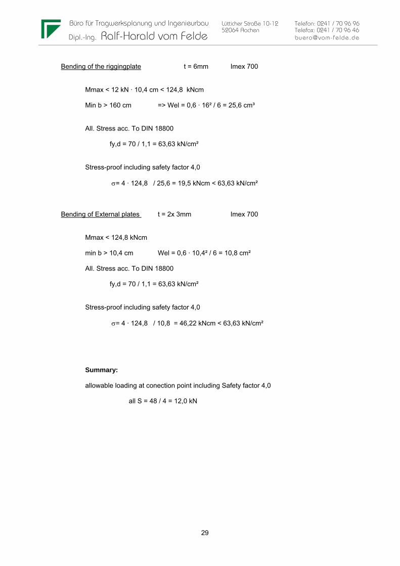
Bending of the riggingplate t = 6mm Imex 700
Mmax < 12 kN · 10,4 cm < 124,8 kNcm
Min b > 160 cm => Wel = 0,6 · 16² / 6 = 25,6 cm³
All. Stress acc. To DIN 18800
fy,d = 70 / 1,1 = 63,63 kN/cm²
Stress-proof including safety factor 4,0
σ= 4 · 124,8 / 25,6 = 19,5 kNcm < 63,63 kN/cm²
Bending of External plates t = 2x 3mm Imex 700
Mmax < 124,8 kNcm
min b > 10,4 cm Wel = 0,6 · 10,4² / 6 = 10,8 cm²
All. Stress acc. To DIN 18800
fy,d = 70 / 1,1 = 63,63 kN/cm²
Stress-proof including safety factor 4,0
σ= 4 · 124,8 / 10,8 = 46,22 kNcm < 63,63 kN/cm²
Summary:
allowable loading at conection point including Safety factor 4,0
all S = 48 / 4 = 12,0 kN

Büro für Tragwerksplanung und Ingenieurbau Lütticher Straße 10-12 Telefon: 0241 / 70 96 96 52064 Aachen Telefax: 0241 / 70 96 46 Dipl.-Ing. Ralf-Harald vom Felde [email protected]
30
F-Bumper
The allowable Loading on the bumper is limited by the loadintroduction at the fixation points.
To determinatee the allowable loading at one fiaxtion point the loadtransmission from the side-plates to the fiaxtion points is idealised as follows:
The total allowable loading at one fixation point is P = P1+P2:
relevant is bending in the plate in the axe of the hole M12
Plate t= 6mm Imex 700
Fixation is by srews M12 with washer i24mm , t=8mm.

Büro für Tragwerksplanung und Ingenieurbau Lütticher Straße 10-12 Telefon: 0241 / 70 96 96 52064 Aachen Telefax: 0241 / 70 96 46 Dipl.-Ing. Ralf-Harald vom Felde [email protected]
31
Determination of P1:
relevant is bending in the plate at the axe of the hole M12 Plate t= 6mm Imex 700
M = P1 · 3,25cm - P1 / 2 · 1,2 cm = P1 · 2,65 cm
effective width: calculation on the base of Heft 240 DAfStb
beff = ty + 2,5 · x (1-x/l) with ty = 2,4cm x = 3,25 cm l = 68,5 cm
=> beff = 2,4 + 2,5 · 3,25 ( 1 - 3,25 / 68,5) = 10,1 cm
to one side beff is limited by the border of the plate => beff = 10,1 / 2 + 2,715 = 7,76 cm
less the hole M12 the net width is beff - 1,2cm = 6,57 cm
=> Wpl = 6,57 · 0,6² / 4 = 0,59 cm³
The allowable stress σ = 70 / 1,1 = 63,63 kN/cm² and the safety factor of 4 leads to
4· P1 · 2,65 / 0,564 < 63,63 => P1 < 63,63 · 0,59 / (4 · 2,65) = 3,54 kN
Determination of P2:
M = P2 ·(20,8-2,415 /20,8) · 2,415cm - P2 / 2 · 1,2 cm = P1 · 1,53 cm
effective width: calculation on the base of Heft 240 DAfStb
beff = ty + 2,5 · x (1-x/l) with ty = 2,4cm x = 2,415 cm l = 20,8 cm
=> beff = 2,4 + 2,5 · 2,415 ( 1 - 2,415 / 20,8) = 7,74 cm
to one side beff is limited by the border of the plate => beff = 7,74 / 2 + 3,515 = 7,38 cm
less the hole M12 the net width is beff - 1,2cm = 6,18 cm
=> Wpl = 6,18 · 0,6² / 4 = 0,56 cm³
The allowable stress σ = 70 / 1,1 = 63,63 kN/cm² and the safety factor of 4 leads to
4· P1 · 1,53 / 0,56 < 63,63 => P1 < 63,63 · 0,56 / (4 · 1,53) = 5,82 kN
Summary
Allowable force at a connection point including a safety factor of 4 is :
all F = 3,54 + 5,82 = 9,4 kN

Büro für Tragwerksplanung und Ingenieurbau Lütticher Straße 10-12 Telefon: 0241 / 70 96 96 52064 Aachen Telefax: 0241 / 70 96 46 Dipl.-Ing. Ralf-Harald vom Felde [email protected]
32
Side plates 6 x 200 mm Imex 700
Conncetion to first loudspeaker by Socket Head shoulder srew M6D8x20 12.9
Concerning Sheraing and tear out see capter rigging-plate
Allowbalew loading including safety fachtor 4
S < 12,0 kN
Bending
Mmax < 9,4 kN · 16 cm < 150,4 kNcm
B =20 cm => Wel = 0,6 · 20² / 6 = 40 cm³
All. Stress acc. To DIN 18800
fy,d = 70 / 1,1 = 63,63 kN/cm²
Stress-proof including safety factor 4,0
σ= 4 · 150,4 / 40 = 15,04 kN/cm² < 63,63 kN/cm²
Front and back -plate 6x40 mm Imex 700
Loading by loadtransmission to fixation point max F = 5,82 kN
leveram e = 3,25 cm
=> M = 5,82 · 3,25 = 18,92 kNcm
Wel = 0,6 ·4² / 6 = 1,6 kNcm
Stress-proof including safety factor 4,0
σ= 4 · 18,92 / 1,6 = 47,3 kNcm < 63,63 kN/cm²

Büro für Tragwerksplanung und Ingenieurbau Lütticher Straße 10-12 Telefon: 0241 / 70 96 96 52064 Aachen Telefax: 0241 / 70 96 46 Dipl.-Ing. Ralf-Harald vom Felde [email protected]
33
5 TOURING ACCESSORIES
5.1 TCBRK-V2
Coupler to support 2 GEOS12-cabinets including rigging-parts (TTC or LYRE)
Fmax = 2 · 0,33 kN = 0,66 kN
Bending Hook (bending at the side with hole 10,5mm relevant)
e = 4,875cm M = 0,66 · 4,875 =3,22 kNcm N = 0,66 · cos30° = 0,57 kN
Cross-section 35x6 mm with hole 10,5mm material IMEX 700
Wpl = (3,5 - 1,05) · 0,6² / 4 = 0,22 cm³A = (3,5-1,05) · 0,6 = 1,47 cm²
Safety–factor: 4
σ= 4 · (3,22 / 0,22 + 0,57 / 1,47 ) = 60,1 kN/cm² < 70 / 1,1 = 63,63 kN/cm²
Bracket: Connection to hook by srew M12 material >= 4.6
Nrd = 22,4 kN > 4 · 0,66 kN
Connection to accessories by balllock M8 1.4305
Shearing acc. to DIN 50141 V = 38 kN > 4 · 0,66 kN
Tear out not relevant

Büro für Tragwerksplanung und Ingenieurbau Lütticher Straße 10-12 Telefon: 0241 / 70 96 96 52064 Aachen Telefax: 0241 / 70 96 46 Dipl.-Ing. Ralf-Harald vom Felde [email protected]
34
5.2 TTC-V2
maximum Loading 1 GeoS12
=> P = 0,33 kN
maximum Bending in TTC- (U 41x38x3 ) IMEX 700
Mmax = 0,33kN · 6,8 = 2,24 kNcm
Wpl > 4 · 0,3· 1,205 ·(1,205/2 + 0,82/2)² = 1,48 cm³
Stress-proof incl. Safety factor 4
σ = 4· M/ Wz,el = 4 · 2,24 / 1,48 = 6,05 kN/cm³ << 70 / 1,1
Connection to Hook by 8mm Ball-lock Pin
Maximum loading on the pin V = 0,33 kN
Shearing and Tear out not relevant.
Connection to GeoS 12- cabinet by plung M8 1.4305
Maximum loading on plung V = 0,33 ·(6,8 + 10,4) / 10,4 = 0,55 kN
1.4305 fy,k > 190 N/mm² Plung M8 A = 0,50cm²
Nrd = 0,5 · 19 /1,1 = 8,63 kN > 4 · 0,55 = 2,2 kN

Büro für Tragwerksplanung und Ingenieurbau Lütticher Straße 10-12 Telefon: 0241 / 70 96 96 52064 Aachen Telefax: 0241 / 70 96 46 Dipl.-Ing. Ralf-Harald vom Felde [email protected]
35
5.3 LYRE-V2
maximum loading by 2 GeoS12 in Hanging- or Groundstack- mode (in combination with GeoS12-SSBRK -V2 and -PSBRK-V2)
=> Loading on one Side-bar Pv = 2 · 0,33kN / 2 = 0,33 kN
horizontal-Stabilisation force = V /100 Due to the jointed connection in one directionone side bar has to transmitt the completet horizontalforce
=> V = 2 · 0,33 / 100 = 0,0066KN
Materiel Steel S235 JR fyk = 240 N/mm² fy,d = 24 / 1,1 = 21,8 kN/cm²

Büro für Tragwerksplanung und Ingenieurbau Lütticher Straße 10-12 Telefon: 0241 / 70 96 96 52064 Aachen Telefax: 0241 / 70 96 46 Dipl.-Ing. Ralf-Harald vom Felde [email protected]
36
Buckling in Side bar in section 4x47,5mm
A = 1,90 cm² Wel = 4,75 · 0,4² / 6 = 0,127 cm³
N = 0,33 kN M = 0,0066 · 21,73= 0,143 kNcm
Buckling: sk = 2 · 21,73 = 43,46 cm i = 0,289 · 0,4 = 0,1156 cm
l = 43,46 / 0,1156 = 376 l* = 376 / 92,9 = 4,05
k = 1 / (4,05·(4,05+0,49) = 0,054
σ = 4·(0,33 / (1,90·0,054) + 0,143 / 0,127) = 17,36 kN/cm² < 21,8 kN/cm²
Buckling in Side bar section b-b
A = 3,5 cm² Izz = 0,79 cm4 Wel,min = 0,61 cm³
N = 0,33 kN M = 0,0066 · 41,73 = 0,275 kNcm
Buckling: sk = 2 · 41,73 = 83,46 cm i = (0,79/3,5)0,5 = 0,475 cm
l = 83,46 / 0,475 = 176 l* = 176 / 92,9 = 1,89
k = 0,215
σ = 4·(0,33 / (3,5·0,215) + 0,275 / 0,61) = 3,56 kN/cm² < 21,8 kN/cm²
bending in section a-a
on the safe side only the two vertical sheets are taken into account
A = 2 · 0,4 · 5,4 = 4,32cm² Wel = 2 · 0,4 · 5,4²/6 = 3,89 cm²
N = 0 kN M = 0,33 · 36cm = 11,9 kNcm
σ = 4·( 11,9 / 3,89) = 12,2 kN/cm² < 21,8 kN/cm²
Büro für Tragwerksplanung und Ingenieurbau Lütticher Straße 10-12 Telefon: 0241 / 70 96 96 52064 Aachen Telefax: 0241 / 70 96 46 Dipl.-Ing. Ralf-Harald vom Felde [email protected]
37
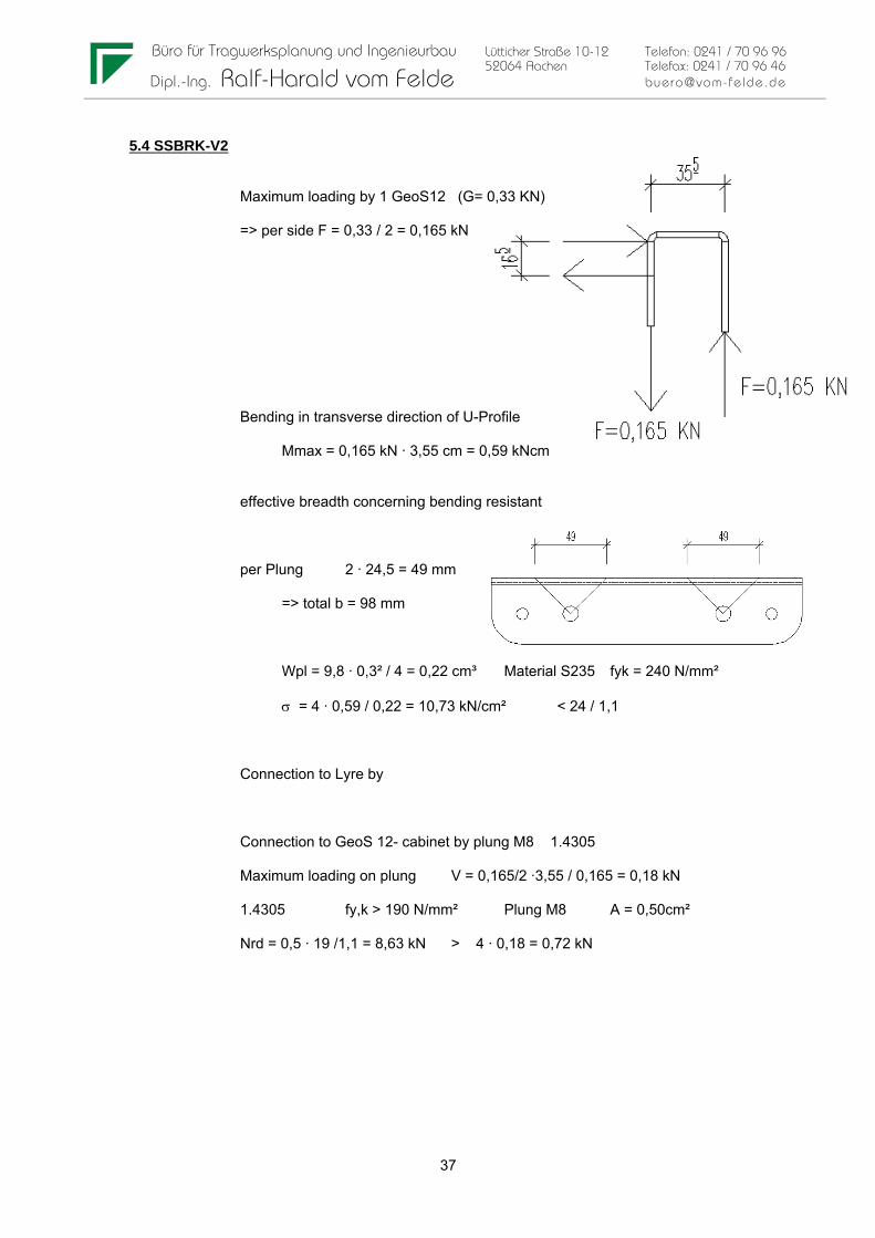
5.4 SSBRK-V2
Maximum loading by 1 GeoS12 (G= 0,33 KN)
=> per side F = 0,33 / 2 = 0,165 kN
Bending in transverse direction of U-Profile
Mmax = 0,165 kN · 3,55 cm = 0,59 kNcm
effective breadth concerning bending resistant
per Plung 2 · 24,5 = 49 mm
=> total b = 98 mm
Wpl = 9,8 · 0,3² / 4 = 0,22 cm³ Material S235 fyk = 240 N/mm²
σ = 4 · 0,59 / 0,22 = 10,73 kN/cm² < 24 / 1,1
Connection to Lyre by
Connection to GeoS 12- cabinet by plung M8 1.4305
Maximum loading on plung V = 0,165/2 ·3,55 / 0,165 = 0,18 kN
1.4305 fy,k > 190 N/mm² Plung M8 A = 0,50cm²
Nrd = 0,5 · 19 /1,1 = 8,63 kN > 4 · 0,18 = 0,72 kN

Büro für Tragwerksplanung und Ingenieurbau Lütticher Straße 10-12 Telefon: 0241 / 70 96 96 52064 Aachen Telefax: 0241 / 70 96 46 Dipl.-Ing. Ralf-Harald vom Felde [email protected]
38
5.5 PSBRK-V2
Maximum loading by 2 x GeoS12 in combination with system LYRE ( 1 on the top part and one one the sup-part)
Load-introduction from cabinet on rigging-part see SSBRK
Theoretique worst-case loading
Material : S235
fy,d = 24 / 1,1 = 21,8 kN/cm²
Thickness: t = 3mm
Proof including safety factor 4
M1 = 4 · 0,165 · 13,15 = 8,7 kNcm
W = 0,3 · 9,5² / 4 = 6,77 cm³ σ = 8,7 / 6,77 << 21,8
M2 = 4 · 0,165 · 7,525 = 4,97 kNcm
W = 0,3 · 5,9² / 4 = 2,61 cm³ σ = 4,97 / 2,61 << 21,8
M3 = 4 · 0,165 · 4,35 = 2,87 kNcm
Wpl > 2· 0,3 ·1,275 · 1,05² = 0,84 σ = 2,87 / 0,84 << 21,8
Connection Top to Sup by Ball-Lock M8 Vsd = 4 · 0,15 kN << Vrd = 38 kN
Connection to LYRE by Vsd = 4 ·0,33 kN

Büro für Tragwerksplanung und Ingenieurbau Lütticher Straße 10-12 Telefon: 0241 / 70 96 96 52064 Aachen Telefax: 0241 / 70 96 46 Dipl.-Ing. Ralf-Harald vom Felde [email protected]
39
5.6 XHBRK
maximum Loading by 4 GEOS12 ( P = 4 · 0,33 = 1,32 kN)
To use in combination with X-Bow or TTC
All proofs including safety factor 4
Bending in Ring-Part
R = (3,5+1,15) / 2 = 2,325cm
Formulas for internal forces after “Stahlbau-Petersen" page 986
Mmax = 0,2387 · 2,325 · 1,32 = 0,73 kNcmN = 0,2387 · 1,32 = 0, 32kN
Wpl = 0,5 · 1,15² / 4 = 0,165 cm³A = 0,5 · 1,15 = 0,575 cm²
σ = 4 · ( 0,73 / 0,165 + 0,32 / 0,575) = 19,9 < 70 / 1,1
Bending at 2-2
M = 1,32 · 1,025 = 1,35 kNcmN = 1,32 kN
Wpl 1,7 · 0,5² / 4 = 0,1063 cm³A = 1,7 · 0,5 = 0,85 cm²
σ = 4 · (1,35 / 0,1063 + 1,32 / 0,85) = 57,01 kN/cm² < 70 / 1,1
Connection to X-Bow
by Ball-lock M8 Vsd = 4 · 1,32 << Vrd = 38 kNtear out not relevant

Büro für Tragwerksplanung und Ingenieurbau Lütticher Straße 10-12 Telefon: 0241 / 70 96 96 52064 Aachen Telefax: 0241 / 70 96 46 Dipl.-Ing. Ralf-Harald vom Felde [email protected]
40
6 FIXED INSTALLATION ACCESSORIES
6.1 UBRK
maximum Load 1 GEOS12 (P= 0,33 kN => 0,165 kN per side)
Two operation modes possible (See draft)
case 1 vertical mode
Moment at corner renfort relevant (e=24,37 cm)
M = 0,165 kN · 24,37 cm = 4,02 kNcm
Wpl > 2· 0,3 ·1,8² / 4 + (9 + 2·1,95) ·0,3² / 4 = 0,78 cm³
σ= 4 ·4,02 / 0,78 = 20,6 kN/cm² < 21,8 kN/cm²
case 2 horizontal mode
M = 0,165 · 32,25 = 5,32 kNcm
Wpl > 0,3 ·(9,0+ 2·1,95)² / 4 = 14,48cm³
σ << 21,8 kN/cm²

Büro für Tragwerksplanung und Ingenieurbau Lütticher Straße 10-12 Telefon: 0241 / 70 96 96 52064 Aachen Telefax: 0241 / 70 96 46 Dipl.-Ing. Ralf-Harald vom Felde [email protected]
41
Forces at connection to sub-structure
case 1 Fh = 0,165 · 32,25 / 62,4 = 0,085 kN
case 2 Fh = 0,165 ·32,25 / 9,0 = 0,59 kN
Bending of backplate (case 2 relevant)
Connection by bolt M12 mit washer 24 mm
distance to border
=> e1 = 28 - 24/2 = 1,4 cm b > 2,4 Wpl = 0,054 cm³
=> all P = 21,8 · 0,05 / 1,4 = 0,84 kN
=> e2 = 19,25 - 24/ 2 = 0,725cmb > 2,4cm Wpl = 0,054 cm³
=> all P = 21,8 · 0,054 / 0, 725 = 1,624 KN
Sum P = 0,84 + 1,624 = 2,464 > 4 · 0,59 = 2,36 kN

Büro für Tragwerksplanung und Ingenieurbau Lütticher Straße 10-12 Telefon: 0241 / 70 96 96 52064 Aachen Telefax: 0241 / 70 96 46 Dipl.-Ing. Ralf-Harald vom Felde [email protected]
42
6.2 LBRK
Accessory fo cable mounted arrays (horizontal and vertical)
Horizontal array maximum load by 3 GeoS12 proof for 4 GeoS12(every third GeoS12 cable mounted)
Bending in longitudinal direction
M max = 1,32 kN · 8,03 cm = 10,6 kNcm
Proof taking only vertical part of cross-section into account
Wpl > 2 · 0,6 · 1,28 · 1,16² = 2,06cm³
σ = 4 · 10,6 / 2,06 = 20,58 << 70/1,1
Bending in transverse direction
F = 1,32 · (8,03 + 10,4 ) / 10,4 = 2,34 kN
=> M = 2,34 · 3,0 = 7,02 kNcm
Connection to Cabinet by pin M8
Effective Width = 2 ·3 - 0,8 = 5,2 cm Wpl = 5,2 ·0,6² / 4 = 0,468cm³
σ = 4 · 7,02 / 0,468 = 60 kN/cm² < 70 /1,1
Connection to cabinet by Socket Head shoulder srew M6 D8x20 12.9
Nsd = 4 · 2,34 = 9,36 kN < Nrd = 0,201cm² · 100 / (1,1,125) = 14,61 kN

Büro für Tragwerksplanung und Ingenieurbau Lütticher Straße 10-12 Telefon: 0241 / 70 96 96 52064 Aachen Telefax: 0241 / 70 96 46 Dipl.-Ing. Ralf-Harald vom Felde [email protected]
43
Fixation on F-Bumper with maximum cluster of 10 GeoS12
Loading per LBRK = 10 · 0,33 / 2 = 1,65 kN + 0,05 kN Bumper
Fixation of LBRK at substructure is only allowed by cables
( a clamped support , for example by fixing it with two srews at at subtsructure isnot allowed)
Bending in longitudinal direction
M max = 1,70 kN · 5,23 cm = 8,89 kNcm
Not relevant see horizontal mode
Bending in transverse direction
F = 1,70 · (5,23 + 16 ) / 16 = 2,25 kN
Proof see horizontal mode with F = 2,34 kN
Connection to cabinet by Socket Head shoulder srew M6 D8x20 12.9
Nsd = 4 · 2,25 = 9,0 kN < Nrd = 0,201cm² · 100 / (1,1,125) = 14,61 kN
At LBRK cable-mounted fixed cluster system the LBRK-part is allways the limiting part ofthe cluster. Proof of structural integrity of rigging-plates and F-Bumper is not necessary.
Maximum possible excentricity of gravity center in cable moounted mode ys < 0,3 mCompare with examples in Annex.

Büro für Tragwerksplanung und Ingenieurbau Lütticher Straße 10-12 Telefon: 0241 / 70 96 96 52064 Aachen Telefax: 0241 / 70 96 46 Dipl.-Ing. Ralf-Harald vom Felde [email protected]
44
6.3 ABRK
ABRK in combinatiuon with Horizontal array maximum load by 3 GeoS12 (every third GeoS12 fixed over ABRK). Claclualations are done for 4 GeoS12.
Loading by the weight of 4 GEOS12 ( P = 4 · 0,33 kN = 1,32)
Theoretique worst case loading
Bending in transverse relevant
P = 1,32 kN => F1 = P ·(2,8+10,4) / 10,4 = 1,68 kN
M = 1,68 · 2,7cm = 4,53 kNcm
effective width b = 1,2 + 2 · 2,7 = 6,6 cm Wpl = 6,6·0,6² / 4 = 0,594 cm³
Proof including safety 4
s = 4 ·4,53 / 0,594 = 30,5 kN/cm² < 70 /1,1 = 63,6 kN/cm²
Fixation to sub-structure and cabinets by Socket Head shoulder srew M6D8x20 12.9
Nsd = 4 · 1,68 = 6,72 kN < Nrd = 0,201cm² · 100 / (1,1,125) = 14,61 kN

Büro für Tragwerksplanung und Ingenieurbau Lütticher Straße 10-12 Telefon: 0241 / 70 96 96 52064 Aachen Telefax: 0241 / 70 96 46 Dipl.-Ing. Ralf-Harald vom Felde [email protected]
45
7 GROUNDSTACK MODE
7.1 Proof of stability
Two cases of horizontal forces are taken into account
1. Impact forces by Persons
Impact force H = 0,3 kN (corresponding to DIN15920-11.)
Height 1,20 m over groundlevel (maximum height in DIN 1055-3)
2. Windforces due to wind beaufort 8
width GeoS12 b = 0,675 m
wind (beaufort 8) q = 0,25 kN/m²
Shape factor cp = 1,3 => w = 1,3 · 0,25 · 0,675 = 0,22 kN/m
For the proof of stability the forces due to wind or impact are taken as exclusive acting forces
=> either wind forces are acting or impact forces.
Impact forces are only applied on clusters with more then 3 cabinets. Clusters with 3 or lesscabinets don‘t attempt a height of near 1,20 and it is assumed that impact forces can not act in aform which could be relevant for the stabiltity of the system.
Security-level: the security level is set in accordance to DIN 4112 to
1,2 towards wind
1,3 toward impact
Geomteric properties for calculations:
Height bumper 0,167 m
weight stabilizers Gstab = 25 kg = 0,25 kN
Retilting moment by bumperweight Ms = 0,25 · 0,97/2 = 0,12 kNm
Height per GeoS12/10 0,345 m weight GeoS12 = 33 kg = 0,33 kN

Büro für Tragwerksplanung und Ingenieurbau Lütticher Straße 10-12 Telefon: 0241 / 70 96 96 52064 Aachen Telefax: 0241 / 70 96 46 Dipl.-Ing. Ralf-Harald vom Felde [email protected]
46
Formulas for proof of stabilitiy
Tilt-Moment: Due to wind Mk-w = 0,22 kN/m · hvp · (hvp/2 + 0,167m)Due to impact Mk-iF = 0,30 kN · min(1,20m, hvp+0,167)
Re-Tilting Moment Due to selfweight Ms = GgeS12 · ec,min · Gstab· 0,97 /2
with ec, min = minimum distance between gravity center of cluster and tilt-point
Calculation of gravity-center ys analogue to chapter 3 with reference point at front connection of1st cabinet.
Distance between front conncetion point and possible tilt points:
ec-1 = e1+ ys for bumper position 5°ec-1 = e1 - ys for bumper postion -5° and 0°
ec2 = 0,97m - ec1
ec-min = min (ec1;ec2)
Proof of stabiltiy: Ms / Mk-w > 1,2
resp. Ms / Mk-iF > 1,3

Büro für Tragwerksplanung und Ingenieurbau Lütticher Straße 10-12 Telefon: 0241 / 70 96 96 52064 Aachen Telefax: 0241 / 70 96 46 Dipl.-Ing. Ralf-Harald vom Felde [email protected]
47
GeoS12 Geometry GSTK-Stabilizers Cluster Height and Depth (projection)height 0,345 [m] h-HP 6,022 [m]width 0,68 [m] weight 0,25 [kN] h-VP 1,621 [m]
Weight GeoS12/10 0,32578 [kN] Ys-Bumper 0,0000 [m]GeoS12/30 0,31328 [kN] Xs-Bumper 0,0000 [m]
GC eys /10 0,122118 [m] Bumper Position Wind-Load (0,25 = beaufort 8 ; 0,12=beaufort 6)exs /10 0,1725 [m] 5; 0 ; -5 5 impact pressure 0,25 [kN/m²]eys /30 0,122402 [m] e1 0,095 w 0,2194 [kN/m]exs /30 0,1725 [m] e2 0,875
Qty GeoS12/10 6 [-] Impact forcesGeoS12/30 0 [-] Distance Cluster-GC to tilt points H 0,3 [KN]
Total Qty 6 [-] ec-1 0,618055 for clusters with less then 4 cabinets the proof of stability Weight 1,95 [kN] ec-2 0,351945 under an impact force is not seen as relevant
min ec 0,351945GeoS12 Cluster gravity center Re-Tilting moment Ms 0,8092 [kNm]
Ys1 [m] 0,523 [m]Xs1 [m] 0,842 [m] Tilt moment Mk MS/Mk
due to wind 0,34771 2,327 > 1,2due to impact force 0,36 2,25 > 1,3
Notice: Bumper angle are set positive when directing upwards Geometric properties Projection local GC of a box global Coord. Of a box global G-Offset
GeoS12-Cluster phi(i,j) psi-0 psi hi hH,i hv,i Gi eys exs Y[m] X[m] ys x G xs x GBox-Nr. Box Position [°] [°] [rad] [m] [m] [m] [kN] [m] [m] [m] [m] [kNm] [kNm]
on / off GeoS12/301 1 0 10 10 0,1745 0,345 0,06 0,34 0,33 0,1221177 0,1725 0,0000 0,0000 0,049 0,0482 1 0 10 20 0,3491 0,345 0,12 0,32 0,33 0,1221177 0,1725 0,0599 0,3398 0,076 0,1503 1 0 10 30 0,5236 0,345 0,17 0,30 0,33 0,1221177 0,1725 0,1779 0,6640 0,121 0,2454 1 0 10 40 0,6981 0,345 0,22 0,26 0,33 0,1221177 0,1725 0,3504 0,9627 0,181 0,3315 1 0 10 50 0,8727 0,345 0,26 0,22 0,33 0,1221177 0,1725 0,5722 1,2270 0,255 0,4056 1 0 10 60 1,0472 0,345 0,30 0,17 0,33 0,1221177 0,1725 0,8365 1,4488 0,341 0,466
GeoS12 Geometry GSTK-Stabilizers Cluster Height and Depth (projection)height 0,345 [m] h-HP 3,739 [m]width 0,68 [m] weight 0,25 [kN] h-VP 2,060 [m]
Weight GeoS12/10 0,32578 [kN] Ys-Bumper 0,0000 [m]GeoS12/30 0,31328 [kN] Xs-Bumper 0,0000 [m]
GC eys /10 0,122118 [m] Bumper Position Wind-Load (0,25 = beaufort 8 ; 0,12=beaufort 6)exs /10 0,1725 [m] 5; 0 ; -5 5 impact pressure 0,25 [kN/m²]eys /30 0,122402 [m] e1 0,095 w 0,2194 [kN/m]exs /30 0,1725 [m] e2 0,875
Qty GeoS12/10 6 [-] Impact forcesGeoS12/30 0 [-] Distance Cluster-GC to tilt points H 0,3 [KN]
Total Qty 6 [-] ec-1 0,312256 for clusters with less then 4 cabinets the proof of stability Weight 1,95 [kN] ec-2 0,657744 under an impact force is not seen as relevant
min ec 0,312256GeoS12 Cluster gravity center Re-Tilting moment Ms 0,7316 [kNm]
Ys1 [m] 0,217 [m]Xs1 [m] 1,019 [m] Tilt moment Mk MS/Mk
due to wind 0,54115 1,352 > 1,2due to impact force 0,36 2,03 > 1,3
Notice: Bumper angle are set positive when directing upwards Geometric properties Projection local GC of a box global Coord. Of a box global G-Offset
GeoS12-Cluster phi(i,j) psi-0 psi hi hH,i hv,i Gi eys exs Y[m] X[m] ys x G xs x GBox-Nr. Box Position [°] [°] [rad] [m] [m] [m] [kN] [m] [m] [m] [m] [kNm] [kNm]
on / off GeoS12/301 1 0 5 5 0,0873 0,345 0,03 0,34 0,33 0,1221177 0,1725 0,0000 0,0000 0,045 0,0532 1 0 0,2 5,2 0,0908 0,345 0,03 0,34 0,33 0,1221177 0,1725 0,0301 0,3437 0,055 0,1643 1 0 0,2 5,4 0,0942 0,345 0,03 0,34 0,33 0,1221177 0,1725 0,0613 0,6873 0,065 0,2764 1 0 0,2 5,6 0,0977 0,345 0,03 0,34 0,33 0,1221177 0,1725 0,0938 1,0307 0,076 0,3885 1 0 0,2 5,8 0,1012 0,345 0,03 0,34 0,33 0,1221177 0,1725 0,1275 1,3741 0,087 0,5006 1 0 0,2 6 0,1047 0,345 0,04 0,34 0,33 0,1221177 0,1725 0,1623 1,7173 0,098 0,611
Calculations cluster with 6 cabinets for Bumper position 5°Bumper 10°, angle setting 10° min ec-2 and max wind or impact
Calculations cluster with 6 cabinets for Bumper position 5°Bumper 5°, angle setting 0,2° min ec-1 and max wind

Büro für Tragwerksplanung und Ingenieurbau Lütticher Straße 10-12 Telefon: 0241 / 70 96 96 52064 Aachen Telefax: 0241 / 70 96 46 Dipl.-Ing. Ralf-Harald vom Felde [email protected]
48
GeoS12 Geometry GSTK-Stabilizers Cluster Height and Depth (projection)height 0,345 [m] h-HP 1,949 [m]width 0,68 [m] weight 0,25 [kN] h-VP 1,374 [m]
Weight GeoS12/10 0,32578 [kN] Ys-Bumper 0,0000 [m]GeoS12/30 0,31328 [kN] Xs-Bumper 0,0000 [m]
GC eys /10 0,122118 [m] Bumper Position Wind-Load (0,25 = beaufort 8 ; 0,12=beaufort 6)exs /10 0,1725 [m] 5; 0 ; -5 5 impact pressure 0,25 [kN/m²]eys /30 0,122402 [m] e1 0,095 w 0,2194 [kN/m]exs /30 0,1725 [m] e2 0,875
Qty GeoS12/10 4 [-] Impact forcesGeoS12/30 0 [-] Distance Cluster-GC to tilt points H 0,3 [KN]
Total Qty 4 [-] ec-1 0,278831 for clusters with less then 4 cabinets the proof of stability Weight 1,30 [kN] ec-2 0,691169 under an impact force is not seen as relevant
min ec 0,278831GeoS12 Cluster gravity center Re-Tilting moment Ms 0,4846 [kNm]
Ys1 [m] 0,184 [m]Xs1 [m] 0,676 [m] Tilt moment Mk MS/Mk
due to wind 0,25744 1,882 > 1,2due to impact force 0,36 1,35 > 1,3
Notice: Bumper angle are set positive when directing upwards Geometric properties Projection local GC of a box global Coord. Of a box global G-Offset
GeoS12-Cluster phi(i,j) psi-0 psi hi hH,i hv,i Gi eys exs Y[m] X[m] ys x G xs x GBox-Nr. Box Position [°] [°] [rad] [m] [m] [m] [kN] [m] [m] [m] [m] [kNm] [kNm]
on / off GeoS12/301 1 0 5 5 0,0873 0,345 0,03 0,34 0,33 0,1221177 0,1725 0,0000 0,0000 0,045 0,0532 1 0 0,2 5,2 0,0908 0,345 0,03 0,34 0,33 0,1221177 0,1725 0,0301 0,3437 0,055 0,1643 1 0 0,2 5,4 0,0942 0,345 0,03 0,34 0,33 0,1221177 0,1725 0,0613 0,6873 0,065 0,2764 1 0 0,2 5,6 0,0977 0,345 0,03 0,34 0,33 0,1221177 0,1725 0,0938 1,0307 0,076 0,3885 0 0 0 0 0,0000 0 0,00 0,00 0,00 0 0 0,0000 0,0000 0,000 0,0006 0 0 0 0 0,0000 0 0,00 0,00 0,00 0 0 0,0000 0,0000 0,000 0,000
Calculations cluster with 4 cabinets for Bumper position 5°Bumper 5°, angle setting 0,2° min ec-1 in comb. with min selfweight under impact

Büro für Tragwerksplanung und Ingenieurbau Lütticher Straße 10-12 Telefon: 0241 / 70 96 96 52064 Aachen Telefax: 0241 / 70 96 46 Dipl.-Ing. Ralf-Harald vom Felde [email protected]
49
GeoS12 Geometry GSTK-Stabilizers Cluster Height and Depth (projection)height 0,345 [m] h-HP 4,946 [m]width 0,68 [m] weight 0,25 [kN] h-VP 1,794 [m]
Weight GeoS12/10 0,32578 [kN] Ys-Bumper 0,0000 [m]GeoS12/30 0,31328 [kN] Xs-Bumper 0,0000 [m]
GC eys /10 0,122118 [m] Bumper Position Wind-Load (0,25 = beaufort 8 ; 0,12=beaufort 6)exs /10 0,1725 [m] 5; 0 ; -5 0 impact pressure 0,25 [kN/m²]eys /30 0,122402 [m] e1 0,679 w 0,2194 [kN/m]exs /30 0,1725 [m] e2 0,291
Qty GeoS12/10 6 [-] Impact forcesGeoS12/30 0 [-] Distance Cluster-GC to tilt points H 0,3 [KN]
Total Qty 6 [-] ec-1 0,310076 for clusters with less then 4 cabinets the proof of stability Weight 1,95 [kN] ec-2 0,659924 under an impact force is not seen as relevant
min ec 0,310076GeoS12 Cluster gravity center Re-Tilting moment Ms 0,7273 [kNm]
Ys1 [m] 0,369 [m]Xs1 [m] 0,920 [m] Tilt moment Mk MS/Mk
due to wind 0,41865 1,737 > 1,2due to impact force 0,36 2,02 > 1,3
Notice: Bumper angle are set positive when directing upwards Geometric properties Projection local GC of a box global Coord. Of a box global G-Offset
GeoS12-Cluster phi(i,j) psi-0 psi hi hH,i hv,i Gi eys exs Y[m] X[m] ys x G xs x GBox-Nr. Box Position [°] [°] [rad] [m] [m] [m] [kN] [m] [m] [m] [m] [kNm] [kNm]
on / off GeoS12/301 1 0 0 0 0,0000 0,345 0,00 0,35 0,33 0,1221177 0,1725 0,0000 0,0000 0,040 0,0562 1 0 10 10 0,1745 0,345 0,06 0,34 0,33 0,1221177 0,1725 0,0000 0,3450 0,049 0,1613 1 0 10 20 0,3491 0,345 0,12 0,32 0,33 0,1221177 0,1725 0,0599 0,6848 0,076 0,2624 1 0 10 30 0,5236 0,345 0,17 0,30 0,33 0,1221177 0,1725 0,1779 1,0090 0,121 0,3575 1 0 10 40 0,6981 0,345 0,22 0,26 0,33 0,1221177 0,1725 0,3504 1,3077 0,181 0,4446 1 0 10 50 0,8727 0,345 0,26 0,22 0,33 0,1221177 0,1725 0,5722 1,5720 0,255 0,518
GeoS12 Geometry GSTK-Stabilizers Cluster Height and Depth (projection)height 0,345 [m] h-HP 2,161 [m]width 0,68 [m] weight 0,25 [kN] h-VP 2,064 [m]
Weight GeoS12/10 0,32578 [kN] Ys-Bumper 0,0000 [m]GeoS12/30 0,31328 [kN] Xs-Bumper 0,0000 [m]
GC eys /10 0,122118 [m] Bumper Position Wind-Load (0,25 = beaufort 8 ; 0,12=beaufort 6)exs /10 0,1725 [m] 5; 0 ; -5 0 impact pressure 0,25 [kN/m²]eys /30 0,122402 [m] e1 0,679 w 0,2194 [kN/m]exs /30 0,1725 [m] e2 0,291
Qty GeoS12/10 6 [-] Impact forcesGeoS12/30 0 [-] Distance Cluster-GC to tilt points H 0,3 [KN]
Total Qty 6 [-] ec-1 0,641966 for clusters with less then 4 cabinets the proof of stability Weight 1,95 [kN] ec-2 0,328034 under an impact force is not seen as relevant
min ec 0,328034GeoS12 Cluster gravity center Re-Tilting moment Ms 0,7625 [kNm]
Ys1 [m] 0,037 [m]Xs1 [m] 1,041 [m] Tilt moment Mk MS/Mk
due to wind 0,54269 1,405 > 1,2due to impact force 0,36 2,12 > 1,3
Notice: Bumper angle are set positive when directing upwards Geometric properties Projection local GC of a box global Coord. Of a box global G-Offset
GeoS12-Cluster phi(i,j) psi-0 psi hi hH,i hv,i Gi eys exs Y[m] X[m] ys x G xs x GBox-Nr. Box Position [°] [°] [rad] [m] [m] [m] [kN] [m] [m] [m] [m] [kNm] [kNm]
on / off GeoS12/301 1 0 -5 -5 -0,0873 0,345 -0,03 0,34 0,33 0,1221177 0,1725 0,0000 0,0000 0,035 0,0592 1 0 0,2 -4,8 -0,0838 0,345 -0,03 0,34 0,33 0,1221177 0,1725 -0,0301 0,3437 0,025 0,1713 1 0 0,2 -4,6 -0,0803 0,345 -0,03 0,34 0,33 0,1221177 0,1725 -0,0589 0,6875 0,016 0,2834 1 0 0,2 -4,4 -0,0768 0,345 -0,03 0,34 0,33 0,1221177 0,1725 -0,0866 1,0314 0,007 0,3955 1 0 0,2 -4,2 -0,0733 0,345 -0,03 0,34 0,33 0,1221177 0,1725 -0,1131 1,3753 -0,001 0,5076 1 0 0,2 -4 -0,0698 0,345 -0,02 0,34 0,33 0,1221177 0,1725 -0,1383 1,7194 -0,009 0,619
Calculations cluster with 6 cabinets for Bumper position 0°Bumper 0°, angle setting 10° min ec-1 and max wind
Calculations cluster with 6 cabinets for Bumper position 0°Bumper -5°, angle setting 0,2° min ec-2 and max wind
Calculations cluster with 4 cabinets not relavant because less cabinets will remove gravitycenter to the middle (ec-min > 0,31 > ec-min = 0,2788 for bumper position5°)

Büro für Tragwerksplanung und Ingenieurbau Lütticher Straße 10-12 Telefon: 0241 / 70 96 96 52064 Aachen Telefax: 0241 / 70 96 46 Dipl.-Ing. Ralf-Harald vom Felde [email protected]
50
GeoS12 Geometry GSTK-Stabilizers Cluster Height and Depth (projection)height 0,345 [m] h-HP 2,056 [m]width 0,68 [m] weight 0,25 [kN] h-VP 2,042 [m]
Weight GeoS12/10 0,32578 [kN] Ys-Bumper 0,0000 [m]GeoS12/30 0,31328 [kN] Xs-Bumper 0,0000 [m]
GC eys /10 0,122118 [m] Bumper Position Wind-Load (0,25 = beaufort 8 ; 0,12=beaufort 6)exs /10 0,1725 [m] 5; 0 ; -5 -5 impact pressure 0,25 [kN/m²]eys /30 0,122402 [m] e1 0,588 w 0,2194 [kN/m]exs /30 0,1725 [m] e2 0,382
Qty GeoS12/10 6 [-] Impact forcesGeoS12/30 0 [-] Distance Cluster-GC to tilt points H 0,3 [KN]
Total Qty 6 [-] ec-1 0,641845 for clusters with less then 4 cabinets the proof of stability Weight 1,95 [kN] ec-2 0,328155 under an impact force is not seen as relevant
min ec 0,328155GeoS12 Cluster gravity center Re-Tilting moment Ms 0,7627 [kNm]
Ys1 [m] -0,054 [m]Xs1 [m] 1,040 [m] Tilt moment Mk MS/Mk
due to wind 0,53197 1,434 > 1,2due to impact force 0,36 2,12 > 1,3
Notice: Bumper angle are set positive when directing upwards Geometric properties Projection local GC of a box global Coord. Of a box global G-Offset
GeoS12-Cluster phi(i,j) psi-0 psi hi hH,i hv,i Gi eys exs Y[m] X[m] ys x G xs x GBox-Nr. Box Position [°] [°] [rad] [m] [m] [m] [kN] [m] [m] [m] [m] [kNm] [kNm]
on / off GeoS12/301 1 0 -10 -10 -0,1745 0,345 -0,06 0,34 0,33 0,1221177 0,1725 0,0000 0,0000 0,029 0,0622 1 0 0,2 -9,8 -0,1710 0,345 -0,06 0,34 0,33 0,1221177 0,1725 -0,0599 0,3398 0,010 0,1733 1 0 0,2 -9,6 -0,1676 0,345 -0,06 0,34 0,33 0,1221177 0,1725 -0,1186 0,6797 -0,009 0,2834 1 0 0,2 -9,4 -0,1641 0,345 -0,06 0,34 0,33 0,1221177 0,1725 -0,1762 1,0199 -0,027 0,3945 1 0 0,2 -9,2 -0,1606 0,345 -0,06 0,34 0,33 0,1221177 0,1725 -0,2325 1,3603 -0,045 0,5056 1 0 0,2 -9 -0,1571 0,345 -0,05 0,34 0,33 0,1221177 0,1725 -0,2877 1,7008 -0,063 0,616
GeoS12 Geometry GSTK-Stabilizers Cluster Height and Depth (projection)height 0,345 [m] h-HP 4,342 [m]width 0,68 [m] weight 0,25 [kN] h-VP 1,860 [m]
Weight GeoS12/10 0,32578 [kN] Ys-Bumper 0,0000 [m]GeoS12/30 0,31328 [kN] Xs-Bumper 0,0000 [m]
GC eys /10 0,122118 [m] Bumper Position Wind-Load (0,25 = beaufort 8 ; 0,12=beaufort 6)exs /10 0,1725 [m] 5; 0 ; -5 -5 impact pressure 0,25 [kN/m²]eys /30 0,122402 [m] e1 0,588 w 0,2194 [kN/m]exs /30 0,1725 [m] e2 0,382
Qty GeoS12/10 6 [-] Impact forcesGeoS12/30 0 [-] Distance Cluster-GC to tilt points H 0,3 [KN]
Total Qty 6 [-] ec-1 0,300652 for clusters with less then 4 cabinets the proof of stability Weight 1,95 [kN] ec-2 0,669348 under an impact force is not seen as relevant
min ec 0,300652GeoS12 Cluster gravity center Re-Tilting moment Ms 0,7089 [kNm]
Ys1 [m] 0,287 [m]Xs1 [m] 0,949 [m] Tilt moment Mk MS/Mk
due to wind 0,44755 1,584 > 1,2due to impact force 0,36 1,97 > 1,3
Notice: Bumper angle are set positive when directing upwards Geometric properties Projection local GC of a box global Coord. Of a box global G-Offset
GeoS12-Cluster phi(i,j) psi-0 psi hi hH,i hv,i Gi eys exs Y[m] X[m] ys x G xs x GBox-Nr. Box Position [°] [°] [rad] [m] [m] [m] [kN] [m] [m] [m] [m] [kNm] [kNm]
on / off GeoS12/301 1 0 -5 -5 -0,0873 0,345 -0,03 0,34 0,33 0,1221177 0,1725 0,0000 0,0000 0,035 0,0592 1 0 10 5 0,0873 0,345 0,03 0,34 0,33 0,1221177 0,1725 -0,0301 0,3437 0,035 0,1643 1 0 10 15 0,2618 0,345 0,09 0,33 0,33 0,1221177 0,1725 0,0000 0,6874 0,053 0,2684 1 0 10 25 0,4363 0,345 0,15 0,31 0,33 0,1221177 0,1725 0,0893 1,0206 0,089 0,3675 1 0 10 35 0,6109 0,345 0,20 0,28 0,33 0,1221177 0,1725 0,2351 1,3333 0,141 0,4586 1 0 10 45 0,7854 0,345 0,24 0,24 0,33 0,1221177 0,1725 0,4330 1,6159 0,209 0,538
Calculations cluster with 6 cabinets for Bumper position -5°Bumper -5°, angle setting 10° min ec-1 and max wind
Calculations cluster with 6 cabinets for Bumper position -5°Bumper -10°, angle setting 0,2° min ec-2 and max wind
Calculations cluster with 4 cabinets not relavant because less cabinets will remove gravitycenter to the middle (ec-min > 0,30 > ec-min = 0,2788 for bumper position5°)

Büro für Tragwerksplanung und Ingenieurbau Lütticher Straße 10-12 Telefon: 0241 / 70 96 96 52064 Aachen Telefax: 0241 / 70 96 46 Dipl.-Ing. Ralf-Harald vom Felde [email protected]
51
Transverse direction:
Impact forces on cluster with 4 GeoS12 relevant (cluster with minimum selfweight in relation to possible horizontal forces)
Mk-iF = 1,2· 0,3 = 0,36 kNm
Weight cluster + bumper G = 1,32 + 0,25 = 1,57 kN
distance to tilt point = 1/2 width of bumper e = 0,675 / 2 = 0,34 m
Ms = 0,34 · 1,57 = 0,534 kNm
Proof: Ms / Mk = 0,534 / 0,36 = 1,48 > 1,30

Büro für Tragwerksplanung und Ingenieurbau Lütticher Straße 10-12 Telefon: 0241 / 70 96 96 52064 Aachen Telefax: 0241 / 70 96 46 Dipl.-Ing. Ralf-Harald vom Felde [email protected]
52
7.2 Strcutural integrity of rigging parts
Maximum internalforces due to selfweight for cluster with 6 GeoS12 , base angle 10° ,angle-setting 10° between all cabinets.
On the safe side the proof of structural integrity is done for windforces on the theoretique maximum height of a cluster Hvp < 6 · 0,345 = 2,07m
Geometric properties see calculations on stability proof page..
Loading on bumper due to selfweight and wind:
G-Cluster = 1,95 kN ys1 = 0,523 m hvp < 2,07 m
Mg = 1,95 · 0,523 = 1,02 kNm due to G
Mw = 0,22 ·2,07² / 2 = 0,47 kNm due to W
Fv = 1,95 KN due to G
Fh = 0,46 kN due to W

Büro für Tragwerksplanung und Ingenieurbau Lütticher Straße 10-12 Telefon: 0241 / 70 96 96 52064 Aachen Telefax: 0241 / 70 96 46 Dipl.-Ing. Ralf-Harald vom Felde [email protected]
53
Internal forces at connection points:
S2 = M / (2·0,288)
=> due to G S2 = 1,77 kN
due to W S2 = 0,82 KN
S1v = Fv/2 · cos 10° - Fh/2 ·sin10° - S2
=> due to G S1v = -0,81 kN
due to W S1v = -0,90 kN
S1h = Fv/2 · sin10° +Fh / 2 · cos 10°
=> due to G S1h = 0,17 kN
due to W S1h = 0,45 kN
S3+S4 = S1v + S2
=> S3 = 0,96 - S4 due to G
S3 = -0,08 - S4 due to W
S4 · 0,187 + S3 · 0,027 = M/2
=> due to G S4 ·0,187 + (0,96-S4) 0,027 = 0,51 kNm
S4 = (0,51 - 0,027·0,96) / (0,187-0,027) = 3,03 kN
S3 = 0,96 - 3,03 = -2,07 kN
due to W S4 = (0,235 + 0,027·0,08) / (0,187 - 0,027) = 1,48 KN
S3 = -0,08 - 1,48 = -1,56 kN

Büro für Tragwerksplanung und Ingenieurbau Lütticher Straße 10-12 Telefon: 0241 / 70 96 96 52064 Aachen Telefax: 0241 / 70 96 46 Dipl.-Ing. Ralf-Harald vom Felde [email protected]
54
Allowable Loading + proof of structural integrity
All parts S235 JR (Except X-Bow V2)
conncetion points to X-Bow:
Tear out at Front connection (S1)
Bumperpart relevant (materiel S235 JR)dL=8,3 mm
e1 = e2 = 15 mm = 1,81 · dL
=> a = 1,69
Vlrd = t · dL · a · fyk / 1,1
Vlrd = 0,6·0,8 ·1,61 · 24 / 1,1 = 16,86 kN
Tear out at back connection
Nearly identic geometric properties Vlrd = 16,86
connection to X-Bow
by 8mm Ball-lock 1.4305 Nirosta
Shearing acc. to DIN 50141 V = 38 kN
Summary + Proof
tear out relevant
=> allowable Loading S [kN] including safety factor =4
all S = 16,86 / 4 = 4,215 kN > S max = 1,77 + 0,82 = 2,59 kN (S2)

Büro für Tragwerksplanung und Ingenieurbau Lütticher Straße 10-12 Telefon: 0241 / 70 96 96 52064 Aachen Telefax: 0241 / 70 96 46 Dipl.-Ing. Ralf-Harald vom Felde [email protected]
55
Bending
Female adapter front
distance to welding-axe e < 3 cm
S1v max = 1,71KN M= 3 · 1,71 = 5,13 kNcm
section b/h = 2 x 0,3 / 3,15 cm Wpl = 0,6·3,15² / 4 = 1,49 cm³
σ = 4 ·5,13 / 1,49 = 13,77 kN/cm² < 24,0 / 1,1 = 21,8 kN/cm²
Male adapter back
e < 7 cm
S2 max = 2,59 KN M= 7 · 2,59 = 19,13 kNcm
section b/h = 0,6 / 6,8 cm Wpl = 0,6·6,8² / 4 = 6,93 cm³
σ = 4 ·19,13 / 6,93 = 11,04 kN/cm² < 24,0 / 1,1 = 21,8 kN/cm²

Büro für Tragwerksplanung und Ingenieurbau Lütticher Straße 10-12 Telefon: 0241 / 70 96 96 52064 Aachen Telefax: 0241 / 70 96 46 Dipl.-Ing. Ralf-Harald vom Felde [email protected]
56
Connection to stabilizer
Tear out at Connection (S4)
Tear out at U-Section relevant (min e1)
dL= 16,2mm
e1 = e2 = 21 mm = 1,29 · dL
=> a = 0,87
Vlrd = t · dL · a · fyk / 1,1
Vlrd = 2 ·0,6· 1,6 ·0,87 · 24 / 1,1 = 36,44 kN
connection by 16mm Bolts > 4.6
Vrd > 2 · 43,9 kN not relevant
Summary + Proof
tear out relevant
=> allowable Loading S [kN] including safety factor =4
all S = 36,44 / 4 = 9,11 kN > S max = 3,03 + 1,48 = 4,51 kN (S4)
Bending stabilizers
Max bending-moment:
max M = 0,5 ·(Mg + Mw + Fh · 0,15 ) = 0,5·(1,02+0,47 + 0,46·0,15) = 0,78 kNm
Cross section closed rectangular tube 5,8x5,3x0,4 cm
Iyy = 2 · 0,4· 4,9³ / 12 + 2 · 5,4·0,4 ·2,45² = 33,8 cm4
Sy = 5,4·0,4·2,45 +2 · 0,4·2,45² / 2 = 7,69cm³
Wpl = 2·7,69 = 15,38 cm³
Proof incl. Safety factor = 4
4· 78 / 15,38 = 20,28 kN/cm² < 24 / 1,1 = 21,8 kN/cm²

Büro für Tragwerksplanung und Ingenieurbau Lütticher Straße 10-12 Telefon: 0241 / 70 96 96 52064 Aachen Telefax: 0241 / 70 96 46 Dipl.-Ing. Ralf-Harald vom Felde [email protected]
57
8 RIGGING SYSTEM RS15
Vertical cluster with maximum 16 Subwoofer RS15
per cabinet 4 rigging-parts ( one at each corner)
Weight of one cabinet incl. Rigging parts G = 65 kg
Maximum loading on one rigging part
Pmax = 16 · 0,65 /4 = 2,6 kN
Connections and plates
between 2 cabinets by 8mm Ball-lock material: 1.4305 Nirosta fyk = 300 n/mm²
between plates by Socket Head shoulder srew M6D8x20 material: 12.9
Ball-Lock is relevant:
shearing Ball-Lock
Vsd = 4 · 2,6 = 10,4 kN (safety factor =4)
allowable Shearing (in acc. to DIN 50141 )
Vrd = 38 kN > Vsd = 10,4 kN

Büro für Tragwerksplanung und Ingenieurbau Lütticher Straße 10-12 Telefon: 0241 / 70 96 96 52064 Aachen Telefax: 0241 / 70 96 46 Dipl.-Ing. Ralf-Harald vom Felde [email protected]
58
bending Ball-Lock
Msd = 4 · 2,6 / 2 · 0,30 cm = 1,56 kNcm
Ball-Lock M8 with inside hole 3,5mm , fyk = 30 kN/cm²
Wpl = 4/3 (0,4³-0,175³) = 0,078 cm³
Mrd = 0,078·30 / 1,1 = 2,12 kNcm > Msd = 1,56 kNcm
interaction
(10,4 / 38)² + (1,56/2,12)² = 0,62 < 1,0
Tear out plates
e1 = e2 = 17,5 mm = 2,11 · dL
=> a = 2,02
Vlrd = t · dL · a · fyk / 1,1
Vlrd = 2 · 0,3·0,8 ·2,02 · 70 / 1,1 = 61,7 kN > Vsd = 10,4 kN
Stresses in plates
Anet = 2 · 0,3 ·(4,5 - 1,0) = 2,1 cm²
Nsd = 10,4 kN
σ = 10,4 / 2,1 << 70 / 1,1 = 63,63 kN/cm²
Connection plates to cabinet
connection to cabinet by 2x M10 A70 per rigging part
Loading per rigging part P = 0,65 / 4 = 0,1625 kN
Loading per screw: Ps = 0,1625 / 2 = 0,08125 kN
excentricity e = 15/2 + 3 + 3 + 6/2 = 16,5mm = 1,65cm
Bending-moment in screw M = 0,08125 · 1,65 = 0,134 kNcm
Screw M10 Wpl = 4/3 · 0,5³ = 0,167 cm³
material A70 fyk = 450 N/mm² ; fubk = 700 N/mm²
σ = 4 · 0,134 / 0,167 = 3,2 kN/cm² << 45 / 1,1
Shearing not relevant

Büro für Tragwerksplanung und Ingenieurbau Lütticher Straße 10-12 Telefon: 0241 / 70 96 96 52064 Aachen Telefax: 0241 / 70 96 46 Dipl.-Ing. Ralf-Harald vom Felde [email protected]
59
Bumper
Total maximum Weight: Clsuter 16 · 0,65 = 10,4 kN
Bumper < 60 kg = 0,60 kN
Total G = 11 kN
Total load distributed on the four corner points Pi = 11 / 4 = 2,75 kN

Büro für Tragwerksplanung und Ingenieurbau Lütticher Straße 10-12 Telefon: 0241 / 70 96 96 52064 Aachen Telefax: 0241 / 70 96 46 Dipl.-Ing. Ralf-Harald vom Felde [email protected]
60
Cross-Section
h 8,00 [cm]b 12,00 [cm]th 0,50 [cm]tb 0,50 [cm]
dl 6,90 [cm]e1 5,03 [cm]
h' 7,50 [cm]b' 11,75 [cm]
Wy 21,45 [cm³]A 8,60 [cm²] Wz-1 58,71 [cm³]
ys 2,63 [cm] Wz-2 18,55 [cm³]Iyy 85,78 [cm4]Izz 169,15 [cm4] (W-pl=2xS)Sy 12,61 [cm³] Wy-pl 25,22 [cm³]Sz 13,33 [cm³] Wz-pl 26,66 [cm³]
b
h
t = const.
ysdL
e1
Proof including safety factor = 4
Section a-a
M = 4 · 2,75 kN · 54,7cm = 601,7 kNcm
Wpl > 0,3 · 7² / 4 + 2 · 0,3 · 3,7 · 3,35 = 11,11 cm³
σ = 601,7 / 11,11 = 54,15 kN/cm² < 70 / 1,1 = 63,63 kN/cm²
Section b-b
M < 4 · 5,5 · 27,7 = 609,4 kNcm
Wpl > 2 · 0,5 · 8,5² / 4 = 18,06 cm³
σ = 609,4 / 18,06 = 33,7 < 70 / 1,1
Section c-c
M = 4 · 5,5 · 27,7 = 609,4 kNcm
Cross-section properties
Wz-2 relevant
σ = 609,4 / 18,55 = 32,85 < 70/1,1 kN/cm²

Büro für Tragwerksplanung und Ingenieurbau Lütticher Straße 10-12 Telefon: 0241 / 70 96 96 52064 Aachen Telefax: 0241 / 70 96 46 Dipl.-Ing. Ralf-Harald vom Felde [email protected]
61
Bolt at Hanging point Bolt M22 fyk / fuk = 50 / 63 kN/cm²
Wpl = 4/3 · 1,1³ = 1,775 cm³ => Mrd = 1,775 · 50 / 1,1 = 80,68 kNcm
A = p · 1,1² = 3,8 cm² => Vrd = 3,8 · 0,4 · 63 / 1,1 = 87 kN
Proof incl. safety = 4
Msd = 4 · 5,5 kN · 3,25 cm = 71,5 kNcm < Mrd
Vsd = 4 · 5,5 = 22 kN < Vrd
Interaction: (71,5 / 87)² + (22/ 87)² = 0,77 < 1,0
Tear out in centrale bar
dL = 22 ,5 mm
e1 = 27 mm = 1,2· dL
e2 > 1,5 dL
=> a = 1,02
Vlrd = t · dL · a · fyk / 1,1
Vlrd = 0,5·2,2 ·1,02 · 70 / 1,1 =71,4 kN > Vsd = 4 · 5,5 = 22 kN