Embed Size (px)
Citation preview
115FUJITSU Sci. Tech. J.,33,2,pp.115-126(December 1997)
UDC 627.395.74: 621.397.2
Broadband Intelligent Network Architecturefor Multimedia-on-Demand Service
VMasaaki Wakamoto VMitsunori Fukazawa(Manuscript received May 28,1997)
This paper proposes a broadband ISDN (B-ISDN) oriented intelligent network (IN) ar-chitecture for a multimedia-on-demand (MOD) service. It demonstrates that IN archi-tecture is effective for MOD service control. Then, this paper proposes an IN call modelfor B-ISDN, which is an essential model for defining an open interface in the IN archi-tecture. The proposed call model can be applied not only to MOD service control, butto control of more advanced B-ISDN multimedia services. Also, an example of MODservice control based on the proposed IN architecture is given.
1. IntroductionVarious multimedia services are expected to
be offered following the deployment of broadbandISDN (B-ISDN) technologies such as ATM switch-ing and optical transmission systems. Multime-dia-on-demand (MOD) services, which provideusers with multimedia information on an on-de-mand basis, are considered to be especially prac-tical to implement. Video-on-demand (VOD) ser-vices such as movie-on-demand is one of the mostprimitive MOD services. Providing MOD servic-es rapidly and efficiently requires a new servicecontrol architecture based on B-ISDN because ex-isting architectures were developed mainly for theplain old telephone service (POTS) and narrow-band ISDN services.
This paper proposes a B-ISDN oriented in-telligent network (IN) architecture for a multime-dia-on-demand (MOD) service. In the IN archi-tecture, services are executed by interworkingbetween a service control node and a switchingnode. Therefore, function allocation and an inter-face between these nodes should be specified todevelop the IN architecture. A call model is anessential model for defining such an interface. Inthis paper, the requirements and a general modelof an MOD service from the service control view-point are described. Next, we explain how the IN
architecture is effective for MOD service control.A new call model is then proposed. The proposedcall model can be applied not only to MOD servicecontrol but to control of the evolution of B-ISDNmultimedia services. Lastly, a VOD service withcommercial messages is described as a control ex-ample based on the proposed IN architecture.
2. Basic concepts of MOD servicecontrol
2.1 RequirementsCompared with conventional broadcast ser-
vices such as CATV, which has a set programmingschedule, an MOD service enables users to inde-pendently select and receive multimedia informa-tion whenever they like. This requires a servicecontrol function to connect users to the multime-dia information source on an on-demand basis. Tosupport a service control function for a networkedMOD service, the following fundamental require-ments must be satisfied:1) Support for evolutionary B-ISDN signaling
capabilityThe service control architecture must allow
for future, complex multimedia services. Signal-ing capability is one of the most important elementsof service control. B-ISDN signaling is evolution-ary; that is, the ITU-T standardizes B-ISDN sig-
116 FUJITSU Sci. Tech. J.,33,2,(December 1997)
M. Wakamoto et al.: Broadband Intelligent Network Architecture for Multimedia-on-Demand Service
naling in stages.1) For example, signaling capabil-ity set 1 (SCS-1) offers specifications for a singlepoint-to-point connection; and the next capabilityset, SCS-2, supports multiconnection and multi-point (or multiparty) connections. Therefore, a ser-vice control architecture must follow B-ISDN sig-naling design standards.2) Support for interoperability and equal access
In a multicarrier, multivendor, and multipro-vider environment, every organization provides itsown functions (i.e., services and resources). Toenable users and information providers (IPs) toaccess these functions from anywhere in the net-work, the functions must be interoperable. Also,in a multiprovider environment, equal access isindispensable. That is, the service control func-tion must give users equal access to every IP.3) Support for customization
Customization of MOD services by IPs mustbe made an easy task for IPs. For example, a cer-tain IP may wish to provide a home shopping ser-vice by enhancing an already existing MOD ser-vice (e.g., a movie-on-demand service). Thisrequires an open interface to the IPs and localiza-tion of a customized component of the service con-trol function.
2.2 MOD service control modelBefore describing a network architecture that
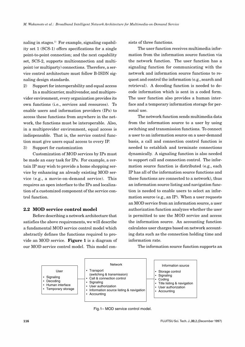
satisfies the above requirements, we will describea fundamental MOD service control model whichabstractly defines the functions required to pro-vide an MOD service. Figure 1 is a diagram ofour MOD service control model. This model con-
sists of three functions.The user function receives multimedia infor-
mation from the information source function viathe network function. The user function has asignaling function for communicating with thenetwork and information source functions to re-quest and control the information (e.g., search andretrieval). A decoding function is needed to de-code information which is sent in a coded form.The user function also provides a human inter-face and a temporary information storage for per-sonal use.
The network function sends multimedia datafrom the information source to a user by usingswitching and transmission functions. To connecta user to an information source on a user-demandbasis, a call and connection control function isneeded to establish and terminate connectionsdynamically. A signaling function is also neededto support call and connection control. The infor-mation source function is distributed (e.g., eachIP has all of the information source functions andthese functions are connected to a network), thusan information source listing and navigation func-tion is needed to enable users to select an infor-mation source (e.g., an IP). When a user requestsan MOD service from an information source, a userauthorization function analyzes whether the useris permitted to use the MOD service and accessthe information source. An accounting functioncalculates user charges based on network account-ing data such as the connection holding time andinformation rate.
The information source function supports an
User
• Signaling• Decoding• Human interface• Temporary storage
Network
• Transport(switching & transmission)
• Call & connection control• Signaling• User authorization• Information source listing & navigation• Accounting
Information source
• Storage control• Signaling• Coding• Title listing & navigation• User authorization• Accounting
Fig.1– MOD service control model.
117FUJITSU Sci. Tech. J.,33,2,(December 1997)
M. Wakamoto et al.: Broadband Intelligent Network Architecture for Multimedia-on-Demand Service
information storage and sends the multimedia in-formation requested by the users. A storage con-trol function supports basic information controlsuch as search, retrieval, and storing. Users’ re-quests and control signals (via the network func-tion) are processed by a signaling function. A cod-ing function is needed to compress video infor-mation. A title listing and navigation function en-ables users to select information titles such asmovie titles. When a user requests a certain in-formation title, a user authorization function an-alyzes whether the user is permitted to access theinformation. An accounting function calculatesthe user charge based on the information source’saccounting data, for example, charges for provid-ing information.
3. Network architecture for an MODservice
3.1 Basic conceptTo construct a network for an MOD service
based on the requirements and MOD service con-trol model described in Chapter 2, we first needto develop a network architecture based on themodel. We should also consider that B-ISDN of-fers us a good opportunity to introduce new ideas.In this chapter, some network architecture alter-natives are considered.
3.1.1 Network architecturealternatives
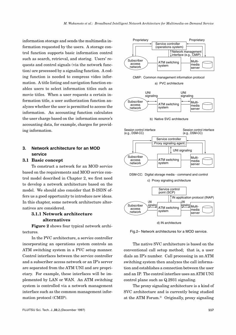
Figure 2 shows four typical network archi-tectures.
In the PVC architecture, a service controllerincorporating an operations system controls anATM switching system in a PVC setup manner.Control interfaces between the service controllerand a subscriber access network or an IP’s serverare separated from the ATM UNI and are propri-etary. For example, these interfaces will be im-plemented by LAN or WAN. An ATM switchingsystem is controlled via a network managementinterface such as the common management infor-mation protocol (CMIP).
The native SVC architecture is based on theconventional call setup method; that is, a userdials an IP’s number. Call processing in an ATMswitching system then analyzes the call informa-tion and establishes a connection between the userand an IP. The control interface uses an ATM UNIcontrol plane such as Q.2931 signaling.
The proxy signaling architecture is a kind ofSVC architecture and is currently being studiedat the ATM Forum.2) Originally, proxy signaling
Proprietary ProprietaryService controller (operations system)
Network managementinterface (e.g., CMIP)
Subscriberaccessnetwork
ATM switchingsystem
Multi-mediaserver
CMIP: Common management information protocol
a) PVC architecture
Subscriberaccessnetwork
ATM switchingsystem
Multi-mediaserver
b) Native SVC architecture
UNIsignaling
UNIsignaling
Subscriberaccessnetwork
ATM switchingsystem
Multi-mediaserver
DSM-CC: Digital storage media - command and control
Session control interface(e.g., DSM-CC)
Session control interface(e.g., DSM-CC)
Service controllerProxy signaling agent
UNI signaling
c) Proxy signaling architecture
Subscriberaccessnetwork
ATM switchingsystem
Multi-mediaserver
UNIsignaling
UNIsignaling
Service controlpoint (SCP)
IN application protocol (INAP)
d) IN architecture
Fig.2– Network architectures for a MOD service.
118 FUJITSU Sci. Tech. J.,33,2,(December 1997)
M. Wakamoto et al.: Broadband Intelligent Network Architecture for Multimedia-on-Demand Service
is used for terminals and subscriber access net-works such as CATV networks which do not sup-port a UNI signaling function. That is, a proxysignaling agent (PSA) acts as an agent of termi-nals (or access networks) for UNI signaling. PSAis located in a service controller. This capabilityis applied to a VOD system in the ATM Forum’sspecification. The interface between a PSA andterminals (or access networks) is called the ses-sion control interface; the digital storage media-command and control (DSM-CC) will typically beused for this interface.
In the IN architecture, a service control point(SCP) controls an ATM switching system by theIN application protocol (INAP).3) Interfaces be-tween an ATM switching system and a subscrib-er access network or an IP’s server use an ATMcontrol plane, as is the case for the native SVCarchitecture.
3.1.2 ConsiderationsThe PVC architecture has the advantage that
it can be rapidly implemented using existing fa-cilities such as a CATV network and LAN. How-ever, the real-time performance will be rather lowbecause it uses network management technolo-gies. Moreover, proprietary interfaces based onLANs or WANs will limit network scale. Thus thisapproach is considered to be suitable only for theinitial stage of an MOD service.
Although the native SVC architecture cansimplify the network configuration, the servicecontrol flexibility is insufficient. For example, anationwide IP will have several server centers.Therefore, user requests should be distributedautomatically to each center according to the traf-fic conditions. In the native SVC architecture, itis not easy to flexibly implement such an infor-mation source listing and navigation function.
The proxy signaling architecture will resolvethe performance issue of the PVC architecture andimprove the information source listing and navi-gation function of the native SVC architecture.Also, because terminals or access networks neednot support a UNI signaling function, the user’s
equipment cost can be reduced, which is consid-ered to be a very important requirement for rapidintroduction and growth of a VOD service. Onthe other hand, current session control interfacessuch as DSM-CC are rather specific to video ser-vices, so the interface should be enhanced orchanged to enable multimedia service control.
The IN architecture will flexibly resolve thenavigation issue. A logical number, for example,the number of a toll-free phone service, which canbe provided by the IN architecture, hides the dis-tribution among centers from the users. Hidingthe distribution is also important for equal access.Moreover, the IN architecture provides a genericplatform for MOD service customization, flexibleaccounting, and authorization for a large-scalenetwork.
Both the proxy signaling architecture and theIN architecture can satisfy the requirements de-scribed in Section 2.1. In this paper, however, wefocus on the IN architecture because of significantissues regarding its development for B-ISDN. Inthe IN architecture, the network function in theMOD service control model is divided into the ser-vice control function (SCF) and the service switch-ing function (SSF)/call control function (CCF). TheMOD service is provided as an IN supplementaryservice.
3.2 Network configurationThis section describes a network configura-
tion for an MOD service based on the IN architec-ture. Because the standardization of B-ISDN sig-naling capability is being done stepwise, wepropose a two-step network construction.
3.2.1 Step 1As described in Section 2.1, the service con-
trol architecture must enable evolution and mustflexibly follow the current stage of B-ISDN sig-naling capability. The B-ISDN signaling capabil-ity is one of the most influential factors in the INarchitecture. SCS-1 is sufficient for an initialMOD service such as a movie-on-demand servicewhich needs only single point-to-point connections.
119FUJITSU Sci. Tech. J.,33,2,(December 1997)
M. Wakamoto et al.: Broadband Intelligent Network Architecture for Multimedia-on-Demand Service
Enhanced MOD services, however, would needmore complex connection control for multiconnec-tion support. For example, a home shopping ser-vice would need a video connection for a video cat-alog and a data connection for an order form. Thisrequires SCS-2, which supports both multiconnec-tion and point-to-multipoint connection control.Early MOD services are likely to trigger a rapidintroduction of a variety of enhanced MOD ser-vices. The IN service control architecture, there-fore, needs to be based on SCS-2 even in its firstimplementation. However, it must still supportSCS-1 as a subset of SCS-2 for simple point-to-point MOD services.
Figure 3 shows a Step 1 network configura-tion. In the early stages of the MOD service’sgrowth, existing CATV networks will be used asthe subscriber access network because of theircost-effectiveness. The CATV network is connect-ed to the ATM switching system via a cable headend system. The cable head end system supportsB-ISDN UNI signaling termination and convertsATM cells into an information stream for theCATV network. The cable head end system alsobroadcasts conventional CATV programs. Massstorage multimedia servers will be connected tothe ATM switching system and will send the re-quested multimedia information to the subscrib-
er’s terminal (e.g., an enhanced set top box or apersonal computer). The service control point(SCP) will control basic call processing (SSF/CCF)in the ATM switching system and the multimediaservers. For Step 1, the conventional signalingsystem No. 7 (SS7) network will be used as thesignaling network for cost-effectiveness. The net-work management system manages each networkelement via the data communication network,which supports the X.25 protocol.
3.2.2 Step 2For Step 2, the network configuration will be
more sophisticated. The IN service control sup-ports connection control that is more complex thanthat supported in SCS-2; for example, it supportscontrol of multipoint-to-point and multipoint-to-multipoint connections. Thus more sophisticatedconcurrent information reception from multipleservers and multimedia conferencing can be pro-vided as IN supplementary services.
Figure 4 shows the Step 2 network configu-ration. Optical subscriber loops will be widelyused, and private networks will be accommodat-ed. The subscriber’s terminals are enhanced (e.g.,a workstation and a multimedia conferencing ter-minal) and support the B-ISDN UNI signalingtermination function. The main differences fromthe network in Step 1 are an ATM signaling net-
Network management system
Data communication network (X.25)
Service control point
SS7 networkCATVprogramprovider
CATVnetwork
Terminal
Cablehead endsystem
ATM switchingsystem
SSF/CCF
ATM switch
ATMswitchingsystem
Multi-mediaserver
Fig.3– Network configuration for a MOD service (Step 1).
Service control point Network management system
ATM switchingsystem
SSF/CCF
ATM switch
ATMswitchingsystem
Multi-mediaserver
ATM signaling network RDP
server
Privatenetwork Gateway
Enhancedterminals
Fig.4– Network configuration for a MOD service (Step 2).
120 FUJITSU Sci. Tech. J.,33,2,(December 1997)
M. Wakamoto et al.: Broadband Intelligent Network Architecture for Multimedia-on-Demand Service
work and a real-time distributed processing (RDP)function. The ATM signaling network provideshigh-speed communications between networknodes. The RDP provides network-wide distribu-tion transparency. The RDP is used for dynamicSCP selection. That is, when a user requests anIN supplementary service, an SCP supporting therequested service is selected. If multiple SCPssupport the requested service, the SCP with thelightest processing load is selected. Ultimately,the RDP is used for mobile multimedia personalcommunication.
4. IN call model for B-ISDNTo implement an MOD service as an IN sup-
plementary service, the IN architecture must in-corporate B-ISDN capability. However, currentIN research, including standardization activitiesat ITU-T, mainly focuses on service control forPOTS and narrowband ISDN services, indicatingthat B-ISDN service control is presently insuffi-cient. When developing the IN architecture in-corporating B-ISDN capability, a call model is anessential part of the IN architecture.4), 5) In thischapter, we focus on an IN call model for B-ISDNthat will be applied to both the Step 1 and Step 2network described in Section 3.2.
4.1 Requirements for the call modelThe call model is a fundamental element for
standardizing the interface between the SCF andSSF/CCF. The call model consists of a call seg-ment model (CSM) and a basic call state model(BCSM). The CSM represents the call control in-formation abstractly from the SCF viewpoint. TheBCSM is a CCF basic call processing model of theCCF which defines call state transitions points incalls (PICs) and detection points (DPs). The easewith which services and design applications canbe developed depends on the flexibility of the callmodel. It should also be remembered that the callmodel must follow the migration of B-ISDN sig-naling capability from SCS-1 to beyond SCS-2.
The conventional call model was studied with
POTS and narrowband ISDN in mind. It is there-fore difficult to directly apply it to B-ISDN ser-vice control, which must manage connection typesother than point-to-point. Research into enhance-ments of the conventional call model has been re-ported.6), 7) These reports discuss only the basic-concept or enhanced BCSM; however, they giveno specifications for the CSM, which must also beenhanced for B-ISDN.
The B-ISDN call model requires the following:1) Multiparty and asymmetric connection
After the Step 1 network has matured, thenumber of services accompanied with unidirec-tional and multiparty connection types will in-crease. Therefore, a call model must be construct-ed for services using a uniform control method forall connection types. Moreover, the call modelmust be designed so that the service logic for thevarious connection types is simplified.2) Multimedia services
After the Step 1 network has matured, it isalso expected that the need for multimedia ser-vices will increase. For such services, subscriberswill be assigned multiple virtual channels (VCs).Thus, a call model must provide flexible VC con-trol. This flexible control includes independentcontrol of each VC and simultaneous control ofmultiple VCs. A call model must also provide con-trol capability for dynamic addition and deletionof a connection in a call.3) Dynamic modification of bearer capability
In an ATM network, which is the most prom-ising network for realizing B-ISDN, a VC is usedas a logical communication path. Since the bear-er capability of a VC can be modified dynamicallyfor each call, new services are expected to use thisfeature. The call model should therefore be de-fined to modify a VC’s parameters when IN ser-vices are executed.4) Communication among various terminals
and serversWith the increase in multimedia services,
various types of terminals and IP servers will beconnected to B-ISDN. A network should support
121FUJITSU Sci. Tech. J.,33,2,(December 1997)
M. Wakamoto et al.: Broadband Intelligent Network Architecture for Multimedia-on-Demand Service
communications among these terminals and serv-ers, and the call model should enable establish-ment of any possible interconnection betweenthem.
4.2 Basic conceptBefore discussing the call model, we must
consider the function arrangement and informa-tion flow between the SCF and SSF/CCF.1) CCF for B-ISDN
If a conventional CCF is used, the servicelogic (SL) in the SCF will be very complicated andthe information flow between the SCF and SSF/CCF will be very large because basic call process-ing in the CCF is too simple to handle multipartyand/or multiconnection services. Therefore, theCCF for B-ISDN should be enhanced to enable asubscriber to set up a multiparty and/or a multi-connection call and add/drop parties or connec-tions during a call.
We have determined that the CCF should bedivided into two types of functional modules (callcontrol modules [CLCs] and connection controlmodules [CNCs]) according to the SCS-2 B-ISDNsignaling capability. The CLC has call signalingtermination and connection coordination func-tions. The CNCs have switching resource man-agement functions, bearer signaling terminationfunctions, and VC management functions. A ba-sic call is executed by interworking the CLC andCNC modules.
As described in Subsection 3.2.1, in the ini-tial stage of the Step 1 network, SCS-1 will besufficient for the initial MOD service, which re-quires only single point-to-point connection. Inthis stage, the CLCs will not need to support allthe functions needed for SCS-2, and the actualservice control will be almost completely handledby the CNCs. That is, the call model based onthis separated module concept can follow the mi-gration of B-ISDN signaling capability from SCS-1 to beyond SCS-2.
2) Information flow between the SCF and SSF/CCFThere are two possible schemes for defining
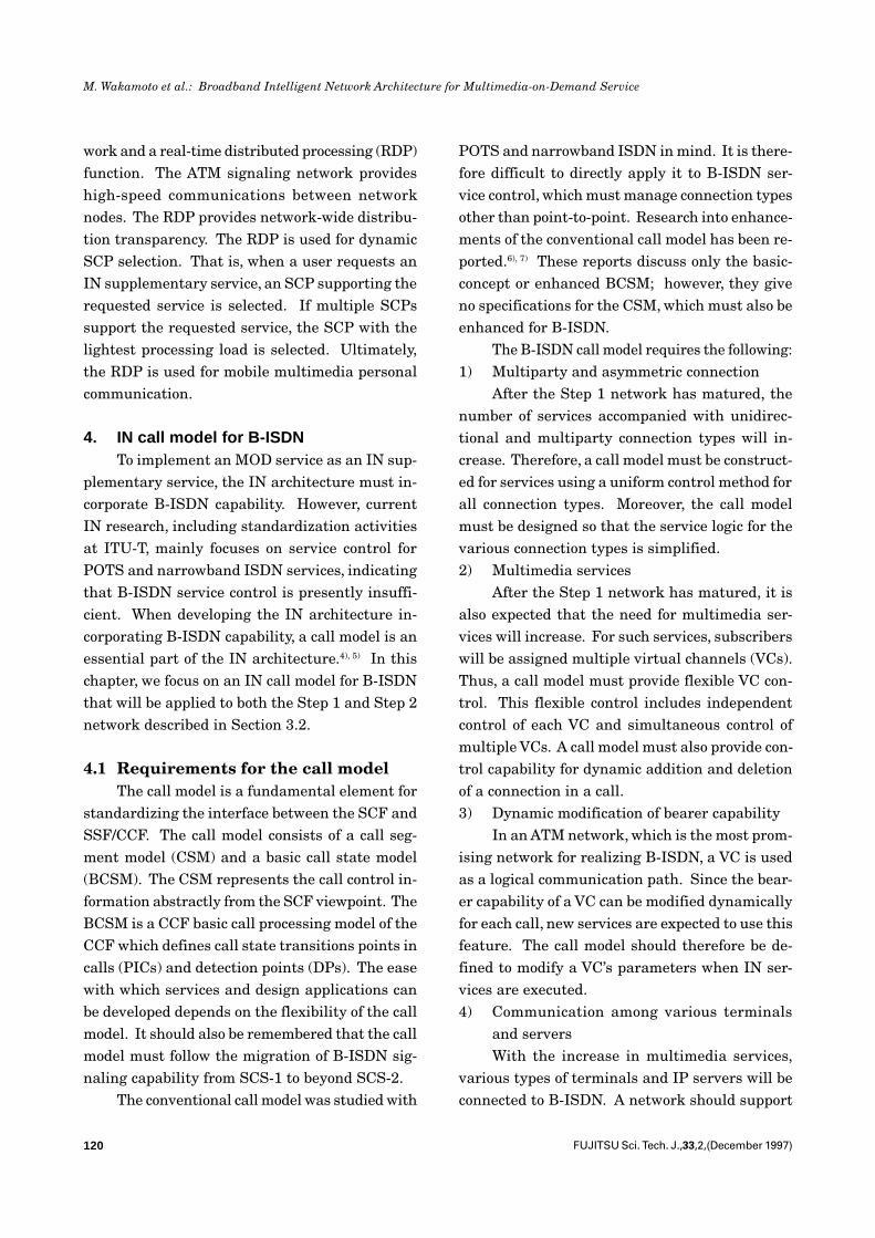
the information flow between the SCF and SSF/CCF when the CCF is enhanced as describedabove. The first scheme is to define an interwork-ing relationship only between the SL and theCLCs. The second scheme is to define multi-in-terworking relationships between the SL, CLCs,and CNCs.
The first scheme hides detailed informationabout connection control states from the SL.Therefore, the SL and the interworking mecha-nism could be simple. On the other hand, for thesecond scheme, the SCF can control the CCF func-tions in more detail because the SL can also di-rectly interwork with the CNCs. We proposea call model based on the first scheme becausethe first scheme is closer to the basic IN purposeof rapid service development and realization ofservice customization and because it can be real-ized by extending the current IN mechanism.Figure 5 shows the proposed CCF structure basedon the first scheme.
We also evaluated the two schemes theoreti-cally from the service control overhead viewpoint.The evaluation results show that the first scheme
SL: Service logicCLC : Call control moduleCNC: Connection control module
SL
SCF
SSF
CCF
CLC
CNC CNC
CLC
Fig.5– CCF functional modules and interworking relationship.
122 FUJITSU Sci. Tech. J.,33,2,(December 1997)
M. Wakamoto et al.: Broadband Intelligent Network Architecture for Multimedia-on-Demand Service
reduces the message traffic between the SCF andSSF/CCF as compared with the second scheme,especially in multiconnection control. This reduc-tion effect becomes more notable as the numberof connections to be controlled increases. The rea-son for this is as follows. In the second scheme,each CNC corresponds to a specific connection, andthe SL must control multiple CNCs concurrentlyto control multiconnection. That is, multiple con-trol messages from the SCF to SSF/CCF are need-ed. On the other hand, for the first scheme, themultiple control orders for connections can be sentby one message to the CLCs.
4.3 Proposed call modelIn this section, we propose an IN call model
for B-ISDN based on the requirements and basicconcept described above.
4.3.1 Call segment model (CSM)The CSM represents call control information,
for example, the connection type, various resourceattributes (e.g., various VC setup parameters), andrelationships among resources (e.g., connectivityrelationship and containment relationship). TheCSM is independent of SSF/CCF implementation.
To satisfy the requirement of Section 4.1,each connection and party should be identified inthe CSM, and their attributes and relationshipsshould be explicitly represented.
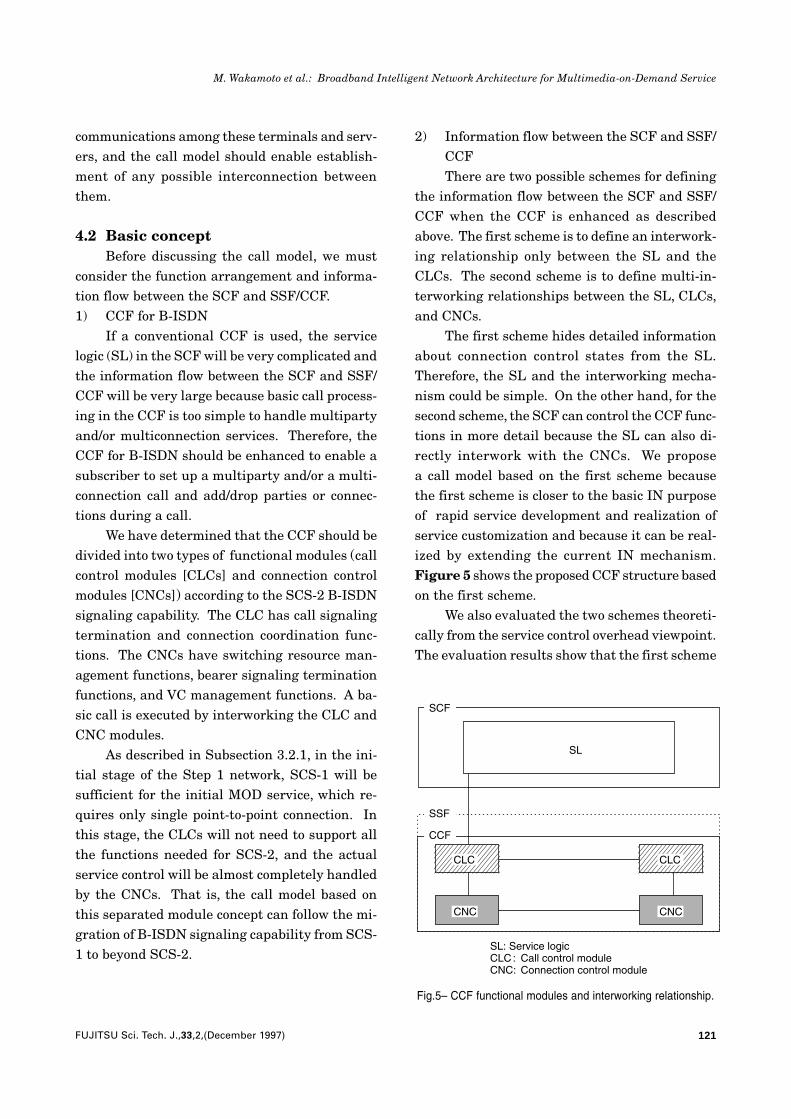
The proposed CSM for B-ISDN consists oflegs, connection points (CPs), access ports (APs),and a call segment (CS). Figure 6 shows the CSM.The figure shows the state in which an IN servicerequest is detected for party A and a correspond-ing IN service is invoked while the multiparty andmulticonnection control function is executed in theCCF as a basic call.
The CSM components are described below.1) Legs
A leg is a VC allocated to a subscriber or to aneighboring switching system by the CCF whichhas the CSM. These VCs are managed by theCNCs and are controlled by the CLC, which de-tects the trigger. A leg has several attributes, for
example, the VC status, information rate, andquality of service (QOS) allocated to the VC.2) Connection points (CPs)
Only single connection (bidirectional point-to-point connection) is considered in the currentIN architecture. The meaning of the term “CP” isnot fully clear because call and connection estab-lishment are the same.
With the separation of CLCs and CNCs inthe CCF for B-ISDN, the SL should be able to dis-tinguish between connections and calls. A CP isdefined as a logical resource which connects legsvia a connection type. The SL can control eachconnection separately by indicating the corre-sponding CP; this meets one of the requirementsdescribed in 4.1 2). A CP is generated for the re-sources (e.g., a speech path and a conferencetrunk) and the corresponding control functionswhich are used to establish the connection in theswitching system. A CP has attributes such asthe reservation status of the corresponding re-source, connection type, and leg information. InFig. 6, the symbols used for CP1 and CP2 repre-sent a conference-type connection and broadcast-type connection, respectively.3) Access port (AP)
An AP is a newly defined component for en-abling control of each party. One AP is created foreach CLC. Each AP is a logical resource that bun-
AP0
PartyA
AP1
AP2
AP3
CS
LEG4
CP2 LEG6
LEG5
LEG3
LEG2
Party C
Party B
Party D
CP1
LEG1
AP: Access port�CP: Connection point�CS: Call segment
DIGITAL
Fig.6– Graphical representation of CSM.
123FUJITSU Sci. Tech. J.,33,2,(December 1997)
M. Wakamoto et al.: Broadband Intelligent Network Architecture for Multimedia-on-Demand Service
dles all VCs controlled by the CNCs under the CLCfor which the AP was created. A CLC-related APthat detects an IN service request is called thecontrol-AP. When a CLC detects a signal for add-ing or dropping a party, the corresponding process-ing (e.g., simultaneous setup/release of multipleVCs) is executed in the CCF containing the CLC.
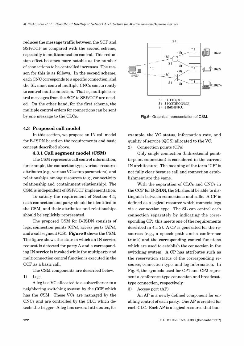
4.3.2 Basic call state model (BCSM)Figure 7 shows a B-ISDN BCSM for an orig-
inating party. The enhanced portions of thisBCSM are summarized as follows:1) “O_Establish_Call” and “O_Establish_
Connection” points in calls (PICs) and“O_Only_Call_Established” detection point(DP) have been defined to support the sepa-ration of call control and connection control.
2) DPs detected at “O_Active” PIC except“O_Mid_Call” and “O_Disconnect_Call” arealso added to enable event detection of add
or drop party/connections in the active state.Because of these enhancements, CCFs can
interact with SCFs at B-ISDN-specific DPs dur-ing basic call processing, and flexible control ofvarious B-ISDN services is possible.
5. MOD service control exampleOne of the most important issues regarding
the popularity of VOD services is user fees. VODservice charges must be competitive with videorental services. One effective method to ensurethat charges are reasonable is to insert a commer-cial message (CM) into the VOD programs. Thischapter describes an example VOD service con-trol with CMs that is based on the proposed INcall model.
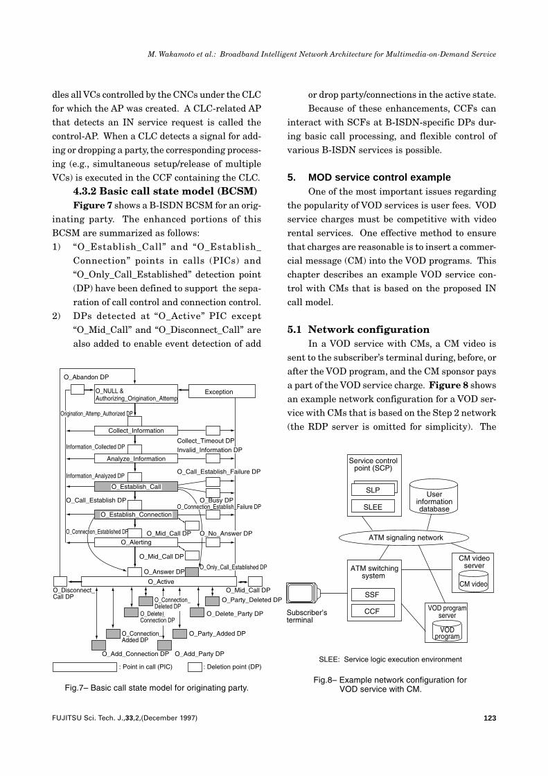
5.1 Network configurationIn a VOD service with CMs, a CM video is
sent to the subscriber’s terminal during, before, orafter the VOD program, and the CM sponsor paysa part of the VOD service charge. Figure 8 showsan example network configuration for a VOD ser-vice with CMs that is based on the Step 2 network(the RDP server is omitted for simplicity). The
O_Abandon DP
O_NULL &Authorizing_Origination_Attemp
Exception
Collect_Information
Collect_Timeout DPInformation_Collected DP
Analyze_Information
Information_Analyzed DP
O_Busy DP
O_Establish_Call
O_Call_Establish DPO_Connection_Establish_Failure DP
O_Establish_Connection
O_Connection_Established DP O_Mid_Call DP
O_Mid_Call DP
O_Alerting
O_Answer DP
O_Disconnect_Call DP
O_ActiveO_Mid_Call DP
O_Connection_Added DP
O_Add_Connection DP
O_Party_Deleted DP
O_Delete_Party DP
O_Party_Added DP
O_Add_Party DP
: Point in call (PIC) : Deletion point (DP)
Origination_Attemp_Authorized DP
Invalid_Information DP
O_Call_Establish_Failure DP
O_No_Answer DP
O_Only_Call_Established DP
O_Delete_Connection DP
O_Connection_Deleted DP
Fig.7– Basic call state model for originating party.
Service controlpoint (SCP)
Userinformationdatabase
ATM signaling network
Subscriber’sterminal
ATM switchingsystem
SSF
CCF
CM videoserver
CM video
VOD programserver
VODprogram
SLEE: Service logic execution environment
SLP
SLEE
Fig.8– Example network configuration forVOD service with CM.
124 FUJITSU Sci. Tech. J.,33,2,(December 1997)
M. Wakamoto et al.: Broadband Intelligent Network Architecture for Multimedia-on-Demand Service
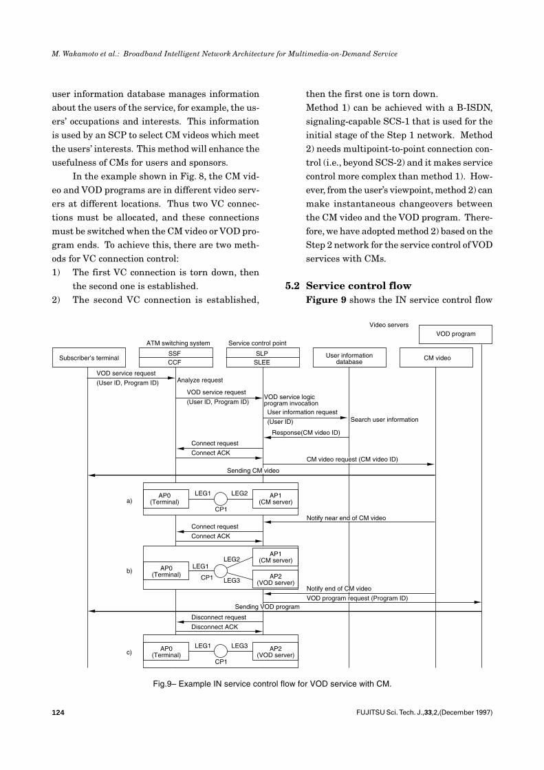
user information database manages informationabout the users of the service, for example, the us-ers’ occupations and interests. This informationis used by an SCP to select CM videos which meetthe users’ interests. This method will enhance theusefulness of CMs for users and sponsors.
In the example shown in Fig. 8, the CM vid-eo and VOD programs are in different video serv-ers at different locations. Thus two VC connec-tions must be allocated, and these connectionsmust be switched when the CM video or VOD pro-gram ends. To achieve this, there are two meth-ods for VC connection control:1) The first VC connection is torn down, then
the second one is established.2) The second VC connection is established,
then the first one is torn down.Method 1) can be achieved with a B-ISDN,signaling-capable SCS-1 that is used for theinitial stage of the Step 1 network. Method2) needs multipoint-to-point connection con-trol (i.e., beyond SCS-2) and it makes servicecontrol more complex than method 1). How-ever, from the user’s viewpoint, method 2) canmake instantaneous changeovers betweenthe CM video and the VOD program. There-fore, we have adopted method 2) based on theStep 2 network for the service control of VODservices with CMs.
5.2 Service control flowFigure 9 shows the IN service control flow
Subscriber’s terminal
ATM switching system Service control point
User informationdatabase
Video serversVOD program
CM videoSSFCCF
SLPSLEE
VOD service request
(User ID, Program ID) Analyze request
VOD service request
(User ID, Program ID)VOD service logicprogram invocationUser information request
(User ID) Search user information
Response(CM video ID)
Connect request
Connect ACK
AP0(Terminal)
AP1(CM server)
Connect request
Connect ACK
AP0(Terminal)
AP1(CM server)
AP2(VOD server)
LEG1
CP1 LEG3
LEG2
Disconnect request
Disconnect ACK
AP0(Terminal)
AP2(VOD server)
LEG1 LEG3
CP1
LEG1 LEG2
CP1
Sending CM video
CM video request (CM video ID)
Notify near end of CM video
Notify end of CM video
VOD program request (Program ID)Sending VOD program
a)
b)
c)
Fig.9– Example IN service control flow for VOD service with CM.
125FUJITSU Sci. Tech. J.,33,2,(December 1997)
M. Wakamoto et al.: Broadband Intelligent Network Architecture for Multimedia-on-Demand Service
of a VOD service with CMs that is based on meth-od 2). The following is an outline of the servicecontrol flow:1) When a subscriber requests a VOD service
with CMs, a request message is sent to theCCF in the ATM switching system. The CCFdetects a trigger and carries out service anal-ysis and user authorization. Then, the SSFsends a trigger to the SCP.
2) Using the service logic program (SLP), theSCP requests the user information databaseto select a CM video that meets the users’interests and then receives the ID of the se-lected video.
3) The SCP requests the SSF/CCF to establisha VC connection between the CM video serv-er and the subscriber terminal.
4) The SCP activates the CM video server andspecifies the CM video. Then the server startssending the CM video. A graphical represen-tation of the CSM in this state is shown inFig. 9 a).
5) When the CM video is nearly finished, theSCP is notified. Using the SLP, the SCP re-quest the SSF/CCF to establish a VC connec-tion between the VOD program server andthe subscriber’s terminal. When the connec-tion is established, the SCP is notified. Agraphical representation of the CSM in thisstate is shown in Fig. 9 b) (LEG 3 is createdand connected to CP 1).
6) When the CM video ends, the SCP is noti-fied. The SCP activates the VOD programserver, and the server starts sending the VODprogram.
7) Using the SLP, the SCP requests the SSF/CCF to tear down the VC connection (LEG2)between the CM video server and the sub-scriber’s terminal. When the connection istorn down, the SCP is notified. A graphicalrepresentation of the CSM in this state isshown in Fig. 9 c).
6. ConclusionWe have proposed a broadband IN architec-
ture for an MOD service. We have focused on thecall model, which is an essential element of theIN architecture. The proposed call model can beapplied not only to MOD service control but tocontrol of evolutionary B-ISDN multimedia ser-vices. An MOD service, namely a VOD service witha commercial message, was described as a controlexample based on the Step 2 network.
We will continue to study issues regardingthe implementation of the proposed architecture,especially for Step 2. For example, we will studyinternetworking with a private network (e.g.,ATM-LAN), real-time distributed processing, andan ATM signaling network.
References1) Baseline Text for Harmonized Signaling Re-
quirements, ITU-T SG11, 1993.2) The ATM Forum Audiovisual Multimedia
Services: Video on Demand ImplementationAgreement 1.0, The ATM Forum, 1995.
3) ITU-T Q.1200 Series Recommendation, ITU-T SG11, 1995 .
4) Wakamoto, M., Fukazawa, M., Kim, M.W.,and Murakami, K.: Intelligent Network Ar-chitecture with Layered Call Model for Mul-timedia-on-Demand Service. Proc. the XV In-ternational Switching Symposium, 1, 1995,pp. 201-205.
5) Wakamoto, M., Fukazawa, M., Kim, M.W.,and Murakami, K.: Phased Network Con-struction for Multimedia-on-Demand Service.Proc. the 7th International Networking Plan-ning Symposium, 1, 1996, pp. 221-226.
6) Bretecher, Y., Vilain, B.: The Intelligent Net-work in a Broadband Context. Proc. the XVInternational Switching Symposium, 2, 1995,pp. 57-61.
7) Maastricht, C., Schalk, E.: Call Modeling ina Broadband IN Architecture. Proc. the XVInternational Switching Symposium, 2, 1995,pp. 340-344.
126 FUJITSU Sci. Tech. J.,33,2,(December 1997)
M. Wakamoto et al.: Broadband Intelligent Network Architecture for Multimedia-on-Demand Service
Masaaki Wakamoto received the B.E.and M.E. degrees in Information Engi-neering from Yokohama National Uni-versity, Japan in 1980 and 1982, respec-tively. He joined Fujitsu LaboratoriesLtd., Kawasaki, Japan in 1982, wherehe has been engaged in research onswitching software CAD, an expert sys-tem for communications networks, andintelligent network architectures. He isa member of the IEEE, IEICE, and IPSJ.
Mitsunori Fukazawa received the B.E.and M.E. degrees in Information Sci-ence from the Science University ofTokyo, Japan in 1983 and 1985, respec-tively. He joined Fujitsu LaboratoriesLtd., Kawasaki, Japan in 1985, wherehe has been engaged in research onswitching software CAD, an expert sys-tem for communications networks, andintelligent network architectures. He isa member of the IEICE.