Embed Size (px)
Citation preview
1
Broadband MIMO-OFDM Wireless CommunicationsGordon L. Stuber, John Barry, Steve W. McLaughlin, Ye (Geoffrey) Li, Mary Ann Ingram, Thomas G.
PrattSchool of Electrical and Computer Engineering
Georgia Institute of Technology
Atlanta, GA 30332
Abstract— Orthogonal frequency division multiplexing(OFDM) is a popular method for high data rate wirelesstransmission. OFDM may be combined with antenna arraysat the transmitter and receiver to increase the diversity gainand/or to enhance the system capacity on time-variant andfrequency-selective channels, resulting in a multiple-inputmultiple-output (MIMO) configuration. This paper exploresvarious physical layer research challenges in MIMO-OFDMsystem design, including physical channel measurements andmodelling, analog beam forming techniques using adaptiveantenna arrays, space-time techniques for MIMO-OFDM, errorcontrol coding techniques, OFDM preamble and packet design,and signal processing algorithms used for performing time andfrequency synchronization, channel estimation, and channeltracking in MIMO-OFDM systems. Finally, the paper considersa software radio implementation of MIMO-OFDM.
Keywords: OFDM, broadband wireless, multiple-inputmultiple-output, synchronization, space-time coding, adaptiveantennas, software radio
I. I NTRODUCTION
Orthogonal frequency division multiplexing (OFDM) hasbecome a popular technique for transmission of signals overwireless channels. OFDM has been adopted in several wire-less standards such as digital audio broadcasting (DAB),digital video broadcasting (DVB-T), the IEEE 802.11a [1]local area network (LAN) standard and the IEEE 802.16a[2] metropolitan area network (MAN) standard. OFDM isalso being pursued for dedicated short range communications(DSRC) for road side to vehicle communications and as apotential candidate for the fourth generation (4G) mobilewireless systems.
OFDM converts a frequency selective channel into a parallelcollection of frequency flat sub-channels. The subcarriershave the minimum frequency separation required to maintainorthogonality of their corresponding time domain waveforms,yet the signal spectra corresponding to the different subcarriersoverlap in frequency. Hence, the available bandwidth is usedvery efficiently. If knowledge of the channel is available atthe transmitter, then the OFDM transmitter can adapt itssignaling strategy to match the channel. Due to the fact thatOFDM uses a large collection of narrowly spaced subchannels,these adaptive strategies can approach the ideal water pouringcapacity of a frequency selective channel. In practice thisis achieved by using adaptive bit loading techniques, where
This research was supported in part by the Yamacraw Mission, of the Stateof Georgia, U.S.A., http://www.yamacraw.org and in part by the NationalScience Foundation under Grant CCR-0121565.
different sized signal constellations are transmitted on thesubcarriers.
OFDM is a block modulation scheme where a block ofNinformation symbols is transmitted in parallel onN subcarri-ers. The time duration of an OFDM symbol isN times largerthan that of a single carrier system. An OFDM modulatorcan be implemented as an inverse discrete Fourier transform(IDFT) on a block ofN information symbols followed by ananalog to digital converter (ADC). To mitigate the effects ofintersymbol interference (ISI) caused by channel time spread,each block ofN IDFT coefficients is typically preceded by acyclic prefix (CP) or a guard interval consisting ofG samples,such that the length of the CP is at least equal to the channellength,M . Under this condition, a linear convolution of thetransmitted sequence and the channel is converted to a circularconvolution. As a result, the effects of the ISI are easily andcompletely eliminated. Moreover, the approach enables thereceiver to use fast signal processing transforms such as afast Fourier transform (FFT) for OFDM implementation [3].Similar techniques can be employed in single carrier systemsas well, by preceding each transmitted data block of lengthNby a cyclic prefix of lengthG, while using frequency domainequalization at the receiver.
Multiple antennas can be used at the transmitter and re-ceiver, an arrangement called a multiple-input multiple-output(MIMO) system. A MIMO system takes advantage of thespatial diversity that is obtained by spatially separated antennasin a dense multipath scattering environment. MIMO systemsmay be implemented in a number of different ways to obtaineither a diversity gain to combat signal fading, or to obtain acapacity gain. Generally there are three categories of MIMOtechniques. The first aims to improve the power efficiency bymaximizing spatial diversity. Such techniques include delaydiversity, space-time block codes (STBC) [4], [5] and space-time trellis codes (STTC) [6]. The second class uses a layeredapproach to increase capacity. One popular example of sucha system is V-BLAST suggested by Foschiniet al. [7] wherefull spatial diversity is usually not achieved. Finally, the thirdtype exploits the knowledge of channel at the transmitter.It decomposes the channel coefficient matrix using SingularValue Decomposition (SVD) and uses these decomposed uni-tary matrices as pre and post filters at the transmitter and thereceiver to achieve near capacity [8].
OFDM has been adopted in the IEEE802.11a LAN andIEEE802.16a LAN/MAN standards. OFDM is also being con-sidered in IEEE802.20a, a standard-in-the-making for main-taining high-bandwidth connections to users moving at speeds
2
up to 60 mph. The IEEE802.11a LAN standard operates atraw data rates up to 54 Mb/s (channel conditions permitting)with a 20 MHz channel spacing, thus yielding a bandwidthefficiency of 2.7 bits/s/Hz. The actual throughput is highlydependent on the medium access control (MAC) protocol.Likewise, IEEE802.16a operates in many modes depending onchannel conditions with a data rate ranging from 4.20 Mb/sto 22.91 Mb/s in a typical bandwidth of 6 MHz, translatinginto a bandwidth efficiency of 0.7 to 3.82 bits/s/Hz. Re-cent developments in MIMO techniques promise a significantboost in performance for OFDM systems. Broadband MIMO-OFDM systems with bandwidth efficiencies on the order of10 bits/s/Hz are feasible for LAN/MAN environments. ThePHY layer techniques described in this paper are intended toapproach 10 bits/s/Hz bandwidth efficiency.
This paper discuss several physical (PHY) layer aspectsbroadband MIMO-OFDM systems. Section II describes thebasic MIMO-OFDM system model. All MIMO-OFDM re-ceivers must perform time synchronization, frequency offsetestimation and correction and parameter estimation. This isgenerally carried out using a preamble consisting of one ormore training sequences. Once the acquisition phase is over,receiver goes into the tracking mode. Section III provides anoverview of the signal acquisition process and investigatessampling frequency offset estimation and correction in Sec-tion IV. The issue of channel estimation is treated in Section V.Section VI considers space-time coding techniques for MIMO-OFDM, while Section VII discusses coding approaches. Adap-tive analog beam forming approaches can be used to providethe best possible MIMO link. Section VIII discusses variousstrategies for beamforming. Section IX very briefly considersmedium access control issues. Section X discusses a softwareradio implementation for MIMO-OFDM. Finally, Section XIwraps up with some open issues concluding remarks.
II. MIMO-OFDM SYSTEM MODEL
A multicarrier system can be efficiently implemented indiscrete time using an Inverse Fast Fourier Transform (IFFT)to act as a modulator and a Fast Fourier Transform (FFT) toact as a demodulator. The transmitted data are the “frequency”domain coefficients and the samples at the output of the IFFTstage are “time” domain samples of the transmitted waveform.Figure 1 shows a typical MIMO-OFDM implementation.
Let X = {X0, X1, . . . , XN−1} denote the length-N datasymbol block. The IDFT of the date blockX yields the timedomain sequencex = {x0, x1, . . . , xN−1}, i.e.,
xn = IFFTN{Xk}(n) . (1)
To mitigate the effects of channel delay spread, a guard intervalcomprised of either a cyclic prefix or suffix is appended tothe sequenceX. In case of a cyclic prefix, the transmittedsequence with guard interval is
xgn = x(n)N
, n = −G, . . . ,−1, 0, 1, . . . , N − 1 (2)
whereG is the guard interval length in samples, and(n)N isthe residue ofn moduloN . The OFDM complex envelopeis obtained by passing the sequencexg through a pair of
Channeldecoder
Datasink
Datasource
MIMOencoder
OFDMmodulator 2
OFDMmodulator 1
OFDMmodulator Q
Channelencoder
OFDMdemodulator 2
OFDMdemodulator 1
OFDMdemodulator L
MIMOdecoder
Signalprocessing for
receiverimplementation
1
1
1
2
2
2
1
2
3
3
3
3
Fig. 1. Q × L MIMO-OFDM system, whereQ and L are the number ofinputs and outputs, respectively.
analog-to-digital converters (to generate the real and imaginarycomponents) with sample rate1/T seconds, and the analogIand Q signals are upconverted to an RF carrier frequency.To avoid intersymbol interference (ISI), the cyclic prefixlength G must equal or exceed the length of the discrete-time channel impulse response,M . The time required totransmit one OFDM symbol,Ts = NT + GT , is called theOFDM symbol time. The OFDM signal is transmitted overthe passband RF channel, received and downconverted to baseband. Due to the cyclic prefix, the discrete linear convolutionof the transmitted sequence with the channel impulse responsebecomes a circular convolution. Hence, at the receiver theinitial G samples from each received block are removed,followed by anN -point discrete Fourier transform (DFT) onthe resulting sequence.
NI G NNIG
Antenna 1
G NI G NNIG
Antenna Q
.
.
.
.
Q(G+NI)
Preamble
G G N
G N
PQ(G+N)Data + pilot
tones
Fig. 2. Frame structure for theQ × L OFDM system.
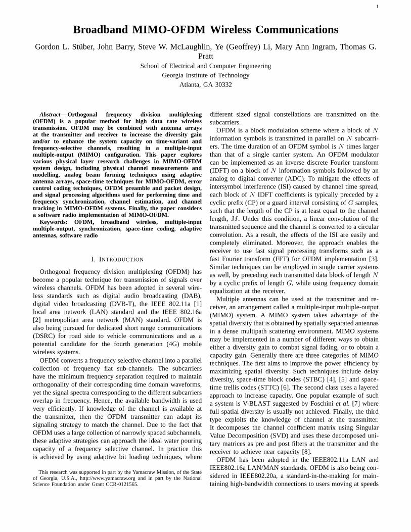
The frame structure of a typical MIMO-OFDM system isshown in Fig. 2. The OFDM preamble consists ofQ trainingsymbols of lengthNI + G, whereG ≤ NI ≤ N , NI =N/I andI an integer that dividesN . Often the length of theguard interval in the training period is doubled, for example inIEEE802.16a [1], to aid in synchronization, frequency offsetestimation and equalization for channel shortening in caseswhere the length of the channel exceeds the length of the
3
guard interval.First consider the preamble portion of the OFDM frame.
The length-NI + G preamble sequences are obtained byexciting everyIth coefficient of a length-N frequency domainvector with a non-zero training symbol from a chosen alphabet(the remainder are set to zero). The frequency domain trainingsequences transmitted from theith antenna are{S(q)
k }Nk=1,
whereq = (c − 1)Q + i and c = 1, 2, . . . , Q The individuallength-NI time domain training sequences are obtained bytaking anN -point IDFT of the sequence{S(q)
k }Nk=1, keeping
the firstNI time-domain coefficients and discarding the rest.A cyclic prefix is appended to each length-NI time-domainsequence. LetHij be the vector of sub-channel coefficientsbetween theith transmit and thejth receive antenna and let{R(l)
k }NI−1k=0 be the received sample sequence at thelth receiver
antenna. After removing the guard interval, the received sam-ples{R(l)
k }NI−1k=0 are repeatedI times and demodulated using
anN -point FFT as
R(l)k = FFTN{r(l)}(k) (3)
=Q∑
q=1
H(q,l)k S
(q)k +W
(l)k (4)
where k = 0, . . . , N − 1. The demodulated OFDM samplematrix Rk of dimension (Q × L) for the kth subcarrier canbe expressed in terms of the transmitted sample matrixSk
of dimension (Q × Q), the channel coefficient matrixHk ofdimension (Q × L) and the additive white Gaussian noisematrix Wk of dimension (Q× L) [24] as
Rk,Q×L = Sk,Q×Q · Hk,Q×L + Wk,Q×L (5)
whereR, H andW can viewed as either a collection ofNmatrices of dimensionQ × L, or as a collection ofQ × Lvectors of lengthN .
A. Preamble Design for MIMO OFDM Systems
Least square channel estimation schemes require that allQ×NI training symbol matricesS(q), q = (c− 1)Q+ k, k =1, . . . , NI be unitary so that onlyQ OFDM symbols areneeded for channel estimation [25]. A straight forward solutionis to make eachSk a diagonal matrix. However, the powerof the preamble needs to be boosted by10 log10Q dB inorder to achieve a performance similar to the case when thepreamble signal is transmitted from all the antennas. Thishas the undesirable effect of increasing the dynamic rangerequirements of the power amplifiers. Hence, methods arerequired so that sequences can be transmitted from all theantennas while still having unitarySk matrices. One approachadapts the work by Tarokhet al. on space-time block codes[5], [26]. For Q = 2, 4 and 8, orthogonal designs exist.For example, forQ = 2 and 4 we can choose the preamblestructures of the form
SAS =[
S1 S1
−S1 S1
], (6)
STS =
S1 S1 S1 S1
−S1 S1 −S1 S1
−S1 S1 S1 −S1
−S1 −S1 S1 S1
, (7)
where S1 is the length-NI vector Sk, k = 1 . . . NI . Thisresults in unitarySk matrices. As it turns out, transmittingthe same sequence from all the antennas in this fashion isadvantageous when performing synchronization. A similarstructure forQ = 8 exists. For other values ofQ, a LSsolution for the channel estimates can be obtained by eithertransmitting more thanQ training sequences, or by makingthe training symbol matrices unitary by using a Gram Schmidtorthonormalization procedure as described in [24].
B. Pilot insertion
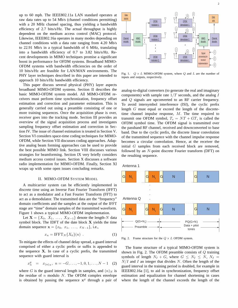
Channel coefficients require constant tracking. This is aidedby inserting known pilot symbols at fixed or variable sub-carrier positions. For example, the IEEE 802.16a standardrecommends the insertion of 8 pilot tones at fixed positionson subcarriers [12, 36, 60, 84, 172, 196, 220, 244] (assumingN = 256). Fig. 3 shows the method for generating the pilotsequences used in the IEEE 802.16a standard. In the downlink(DL) and the uplink (UL), the shift register is initialized withsequences as shown. A ’0’ at the outputPn is mapped to +1and a ’1’ is mapped to -1. For a MIMO system withQ = 2and 4 antennas, the pilot sequencespn can be coded overspace and time to form structures in (6) and (7), respectively,thereby admitting a simple least squares channel estimate. Formore information on the pilot sequence construction, readerscan refer to [27].
1 111098765432
wk
MSB LSB Initialization DL: 1 1 1 1 1 1 1 1 1 1 1 Sequences UL: 1 0 1 0 1 0 1 0 1 0 1
Fig. 3. Pilot tone generation.
III. SYNCHRONIZATION IN THE ACQUISITION MODE
Time and frequency synchronization can be performedsequentially in the following steps [28].
Step I: Coarse Time Synchronization and Signal Detection -Coarse time acquisition and signal detection locates the start ofan OFDM frame over an approximate range of sample values.Due to the presence of the cyclic prefix (or suffix), coarsetime acquisition during the preamble can be performed by
4
correlating the received samples that are at a distance ofNI
from each other over a length-G window ([25], [29]), viz.
nj,coarse = arg max︸︷︷︸n
{φj,n} . (8)
where φj,n =∑G−1
k=0 (r∗j,n+k · rj,n+k+NI). In addition to
maximizing φj,n, it should also exceed a certain thresholdto reduce the probability of false alarm(PFA). We chose thethreshold to be 10% of the incoming signal energy of thecorrelation window.
Step II: Frequency Offset Estimation in the Time Domain-Any frequency offset between the transmitter and the receiverlocal oscillators is reflected in the time domain sequence asa progressive phase shiftθ = 2πγNI/N , where γ is thefrequency offset and is defined as the ratio of the actualfrequency offset to the inter-carrier spacing. A frequency offsetestimate of up to±I/2 subcarrier spacings can be obtainedbased on the phase of the autocorrelation function in (8) asfollows:
γj =I
2π� {φnj,coarse}, (9)
where nj,coarse is the optimum coarse timing acquisitioninstant and I = N/NI . The frequency offset can thenbe removed from the received sample sequence by multi-plying it with exp {−j2πγn/NI} during the preamble andexp {−j2πγn/N} during the data portion. Note that by re-ducing the length of the training symbol by a factor ofI, therange of the frequency offset estimate in the time domain canbe increased by a factor ofI.
Step III: Residual Frequency Offset Correction - Should therange of the time domain frequency offset estimation be in-sufficient, frequency domain processing can be used. Supposethat the same frequency domain training sequence{S(q)
k }Nk=1
is transmitted from all the antennas. The residual frequencyoffset, that is an integer multiple of the subcarrier spacing,can be estimated by computing a cyclic cross-correlation of{S(q)
k }Nk=1 with the received, frequency corrected (from Step
II), demodulated symbol sequence, viz.,
χk =N−1∑n=0
S(q)∗(k+n)N
R(1)c
n k = 0, 1, . . . , N − 1, (10)
where
R(1)c
n = FFTN
{r(1)n ej2πγMLn/NI
}. (11)
The residual frequency offset is estimated asΓ =arg max{|χk|}, k = 0, 1, . . . ,N − 1. Note that the fractionalpart of the relative frequency offset is estimated in the timedomain in Step II while the integer part is estimated in thefrequency domain in Step III.
Step IV: Fine Time Synchronization - Fine time acqui-sition locates the start of the useful portion of the OFDMframe to within a few samples. Once the frequency offsetis removed, fine time synchronization can be performed bycross-correlating the frequency corrected samples with the
transmitted preamble sequences. The fine time synchronizationmetric is
nj,fine = arg max︸︷︷︸n
{ψj,n} , (12)
where ψj,n =∑Q
q=1
∣∣∣∑NI−1k=0 (s∗q,k · rj,n+k)
∣∣∣. For systemsusing 2 and 4 and 8 transmit antennas using the orthogonaldesigns discussed earlier = only one cross correlator is neededper receiver antenna. Once again the threshold is set at 10%of the energy contained inNI received samples. Since finetime synchronization is computationally expensive process, itis carried out for a small window centered around the coarsetime synch. instantnj,coarse.
Finally the net time synchronization instant for the entirereceiver is selected to benopt = 1
L
∑Lj=1 nj,fine. An added
negative offset of a few samples is applied to the fine timesynchronization instant in order to ensure that the OFDMwindows for all the receivers falls into an ISI free zone.
A. Example
Consider a2 × 2 and a4 × 4 broadband MIMO-OFDMsystem [2] operating at a carrier frequency of 5.8 GHz onthe SUI-4 channel shown below. The OFDM signal occupiesa bandwidth of 4.0 MHz. The uncorrected frequency offset(Γ + γ) is 1.25 subcarrier spacings. The OFDM blocksize is
TABLE I
SUI-4 CHANNEL MODEL
Tap 1 Tap 2 Tap 3 UnitsDelay 0 1.5 4.0 µs
Power (omni ant.) 0 -4 -8 dBDoppler fm 0.2 0.15 0.25 Hz
N = 256, and the guard interval is kept atN/4 = 64. Out of256 tones, the dc tone and 55 other tones at the band edgesare set to zero. Hence, the number of used tonesNu=200. Thelength of the sequences used in the preamble is varied fromNto N/2 to N/4. The preamble insertion period,P , is chosento be 10. STBCs are used to encode the data. For a2 × 2system, the Alamouti STBC is used with code rate 1, whereasfor a 4 × 4 system, code rate is3/4 [26]. In the data mode,each of the tones is modulated using a 16-QAM constellationand no channel coding is employed. Least squares channelestimates obtained using the preamble are used to process theentire frame [28]. For training sequences of lengthNI < N ,frequency domain linear interpolation and extrapolation areused. Afterwards, frequency domain smoothing is used, suchthat channel estimates at the band-edges are kept as they are,whereas all the other channel estimates are averaged using
H(q,j)k =
H(q,j)k−1 + H
(q,j)k+1
2. (13)
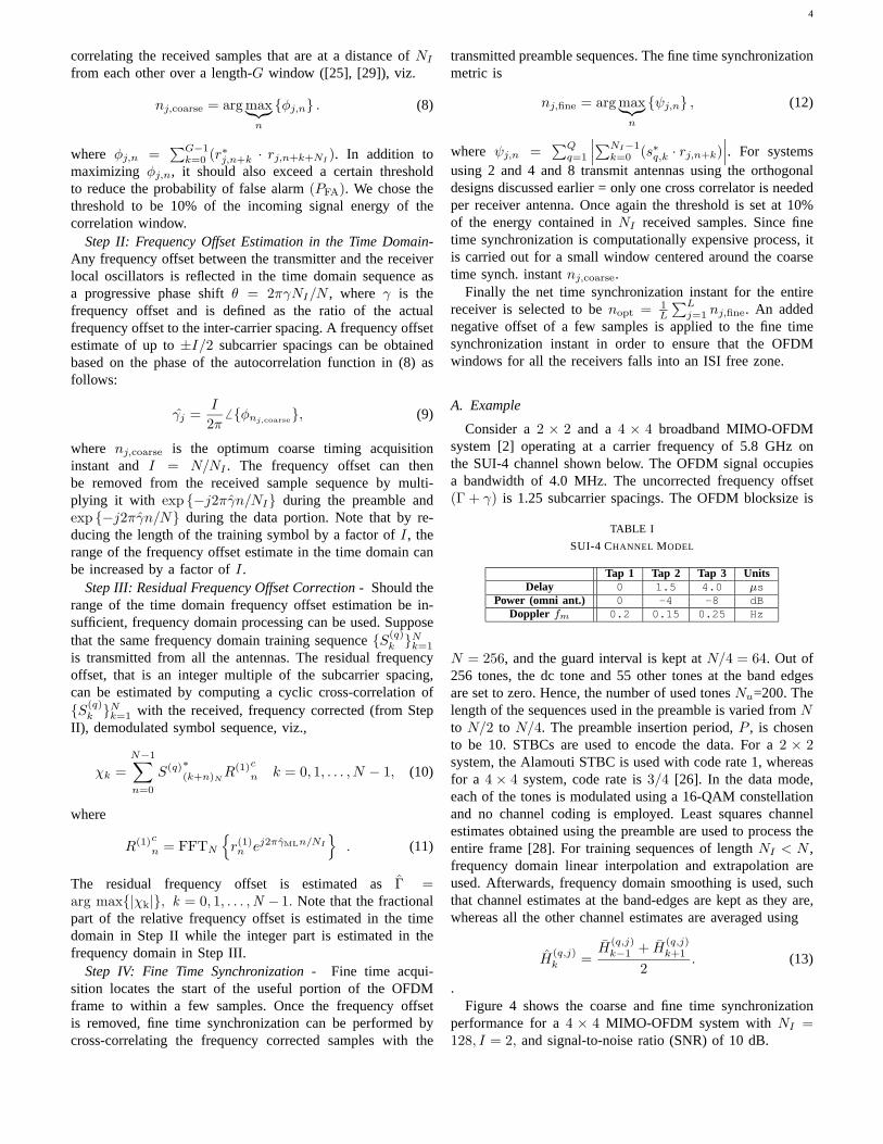
.Figure 4 shows the coarse and fine time synchronization
performance for a4 × 4 MIMO-OFDM system withNI =128, I = 2, and signal-to-noise ratio (SNR) of 10 dB.
5
−2
0
2
Rea
l {r 1 }
−2
0
2
Imag
{r 1 }
0
0.5
1
Φn
200 400 600 800 1000 1200 1400 1600 1800 20000
0.5
Ψn
n
Fig. 4. Coarse and fine time synchronization for a4× 4 system withNI =128, SNR=10 dB, freq. off.Γ + γ = 1 + 0.25. Steps IB, IIIB.
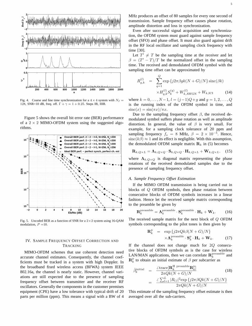
Figure 5 shows the overall bit error rate (BER) performanceof a 2 × 2 MIMO-OFDM system using the suggested algo-rithms.
−2 0 2 4 6 8 10 12 14 16 18 2010
−5
10−4
10−3
10−2
10−1
BE
R
Eb/No (dB)
Overall BER perf. 2 × 2 − I=4, N=256, Nu=200
Overall BER perf. 2 × 2 − I=2, N=256, Nu=200
Overall BER perf. 2 × 2 − I=1, N=256, Nu=200
Overall BER perf. 2 × 2 − I=1, N=256, Nu=256
Ideal BER perf. − perfect synch, perfect ch. est
Fig. 5. Uncoded BER as a function of SNR for a2×2 system using 16-QAMmodulation,P =10.
IV. SAMPLE FREQUENCYOFFSETCORRECTION AND
TRACKING
MIMO-OFDM schemes that use coherent detection needaccurate channel estimates. Consequently, the channel coef-ficients must be tracked in a system with high Doppler. Inthe broadband fixed wireless access (BFWA) system IEEE802.16a, the channel is nearly static. However, channel vari-ations are still expected due to the presence of samplingfrequency offset between transmitter and the receiver RFoscillators. Generally the components in the customer premisesequipment (CPE) have a low tolerance with typical drift of 20parts per million (ppm). This means a signal with a BW of 4
MHz produces an offset of 80 samples for every one second oftransmission. Sample frequency offset causes phase rotation,amplitude distortion and loss in synchronization.
Even after successful signal acquisition and synchroniza-tion, the OFDM system must guard against sample frequencyoffset (SFO) and phase offset. It must also guard against driftin the RF local oscillator and sampling clock frequency withtime [30].
Let T ′ �= T be the sampling time at the receiver and letβ = (T ′ − T )/T be the normalized offset in the samplingtime. The received and demodulated OFDM symbol with thesampling time offset can be approximated by
R(l)g,k =
Q∑q=1
exp {j2πβgk(N +G)/N} sinc(βk)
×H(l)q,kS
(q)k +W
(l)k,AWGN +Wk,ICI (14)
wherek = 0, . . . , N−1, l = (j−1)Q+g andg = 1, 2, . . . , Qis the running index of the OFDM symbol in time, andsinc(x) = sin(πx)/πx.
Due to the sampling frequency offsetβ, the received de-modulated symbol suffers phase rotation as well as amplitudedistortion. In general, the value ofβ is very small. Forexample, for a sampling clock tolerance of 20 ppm andsampling frequencyfs = 8 MHz, β = 2 × 10⁻⁵. Hence,sinc(kβ) ≈ 1 and its effect is negligible. With this assumption,the demodulated OFDM sample matrixRk in (5) becomes
Rk,Q×L = Λk,Q×Q · Sk,Q×Q · Hk,Q×L + Wk,Q×L. (15)
where Λk,Q×Q is diagonal matrix representing the phaserotations of the received demodulated samples due to thepresence of sampling frequency offset.
A. Sample Frequency Offset Estimation
If the MIMO OFDM transmission is being carried out inblocks of Q OFDM symbols, then phase rotation betweenconsecutive blocks of OFDM symbols increases in a linearfashion. Hence let the received sample matrix correspondingto the preamble be given by
Rpreamblek = Λpreamble
k · Spreamblek · Hk + Wk. (16)
The received sample matrix for the next block ofQ OFDMsymbols corresponding to the pilot tones is then given by
Rpk = exp {j2πQkβ(N +G)/N}
×Λpreamblek · Sp
k · Hk + Wk. (17)
If the channel does not change much for 2Q consecu-tive blocks of OFDM symbols as is the case for wirelessLAN/MAN applications, then we can correlateRpreamble
k andRp
k to obtain an initial estimate ofβ per subcarrier as
βinitialk =
� trace[RH preamblek Rp
k]2πQk(N +G)/N
(18)
=� ∑L
l=1 |Rl,l|2exp {j2πβQk(N +G)/N}2πQk(N +G)/N
This estimate of the sampling frequency offset estimate is thenaveraged over all the sub-carriers.
6
B. Channel Estimation
Once initial estimates ofβ are obtained, channel estimationcan be carried out using the Least Squares (LS) technique as
Hk = BHk (BkBH
k )−1Rk, (19)
where Bk = ΛkSk. This ensures that the initial effect ofthe sampling frequency offset is taken into account whenthe channel is estimated. More elaborate channel estimationschemes are considered in the Section V.
C. Sampling Frequency Offset Tracking
Once initial estimates ofβ are obtained, open loop samplingfrequency offset estimation is obtained by minimizing themetric
min(trace
[(Rk − ΛkC
pk)H(Rk − ΛkC
pk)
]), (20)
whereCpk = Sp
kHk. This results in the LS solution of the type
Λk = RkCp Hk (Cp
kCp Hk + δI)−1, (21)
whereδ is a small number of the order of1×10−5 introducedto guard against ill-conditioned matrices andI is the identitymatrix. If the variance of the noise at the receiver is knownthen this factor can be applied instead ofδ. From Λk, thenew value of sampling frequency offset may be extracted bycorrelating the diagonal elements of theΛk matrix as
βnewk =
�{∑Q−1
q=1 Λ∗q,q,kΛq+1,q+1,k
}2πk(N +G)/N
. (22)
The new value ofβnewk is then passed through a first order
low pass filter and the output of the filter is used to obtainthe filtered estimate ofβ. This then is used to form the newestimateΛnew
k . The sampling frequency offset in the trackingmode is then compensated for asRnew
k = (Λnewk )−1Rk.
D. Example
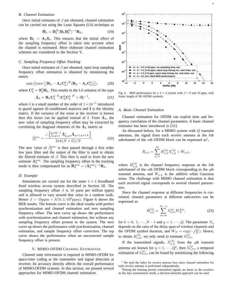
Simulations are carried out for the same4 × 4 broadbandfixed wireless access system described in Section III. Thesampling frequency offsetβ is 10 parts per million (ppm)and is allowed to vary around that value in a random walk.Henceβ = 10ppm + N (0, 1/106ppm). Figure 6 shows theBER results. The bottom curve is the ideal results with perfectsynchronization and channel estimation and zero samplingfrequency offset. The next curve up shows the performancewith synchronization and channel estimation, but without anysampling frequency offset present in the system. The nextcurve up shows the performance with synchronization, channelestimation, and sample frequency offset correction. The topcurve shows the performance when an uncorrected samplefrequency offset is present.
V. MIMO-OFDM CHANNEL ESTIMATION
Channel state information is required in MIMO-OFDM forspace-time coding at the transmitter and signal detection atreceiver. Its accuracy directly affects the overall performanceof MIMO-OFDM systems. In this section, we present severalapproaches for MIMO-OFDM channel estimation.
−4 −2 0 2 4 6 8 10 12 14 1610
−7
10−6
10−5
10−4
10−3
10−2
10−1
100
BE
R
Eb/No (dB)
4 × 4 − I=1 β=10 ppm, no sampling freq. est.4 × 4 − I=1 β=10 ppm, open loop timing rec. and chan. est.4 × 4 − I=1 β=0 ppm, open loop timing rec. and chan. est.4 × 4 − I=1 β=0, ideal BER performance
Fig. 6. BER performance for a4× 4 system withβ = 0 and 10 ppm, withframe length of 80 OFDM symbols.
A. Basic Channel Estimation
Channel estimation for OFDM can exploit time and fre-quency correlation of the channel parameters. A basic channelestimator has been introduced in [31].
As discussed before, for a MIMO system withQ transmitantennas, the signal from each receive antenna at thekthsubchannel of thenth OFDM block can be expressed as1,
Rn,k =Q∑
q=1
H(q)n,kX
(q)n,k +Wn,k,
where H(q)n,k is the channel frequency response at thekth
subchannel of thenth OFDM block corresponding to theqthtransmit antenna, andWn,k is the additive white Gaussiannoise. The challenge with MIMO channel estimation is thateach received signal corresponds to several channel parame-ters.
Since the channel response at different frequencies is cor-related, channel parameters at different subcarriers can beexpressed as
H(q)n,k =
No−1∑m=0
h(q)n,mW
kmN , (23)
for k = 0, 1, · · · , N −1 andq = 1, · · · , Q. The parameterNo
depends on the ratio of the delay span of wireless channels andthe OFDM symbol duration, andWN = exp(− 2π
N ). Hence,to obtainH(q)
n,k, we only need to estimateh(q)n,m.
If the transmitted signals,X(q)n,k from the qth transmit
antenna are known forq = 1, · · · , Q2, then h(q)n,m, a temporal
estimation ofh(q)n,m, can be found by minimizing the following
1 We omit the index for receive antenna here since channel estimation foreach receive antenna is performed independently.
2During the training period, transmitted signals are know to the receiver;In the data transmission mode, a decision-directed approach can be used
7
cost function,
N−1∑k=0
∣∣∣∣∣Rn,k −Q∑
q=1
No−1∑m=0
h(q)n,mW
kmK x
(q)n,k
∣∣∣∣∣2
. (24)
Direct calculation in [31] yields
A(11)n · · · A
(Q1)n
... · · ·...
A(1Q)n · · · A
(QQ)n
h(1)n
...
h(Q)n
=
b(1)n
...
b(Q)n
, (25)
or
h(1)n
...
h(Q)n
=
A(11)n · · · A
(Q1)n
... · · ·...
A(1Q)n · · · A
(QQ)n
−1
b(1)n
...
b(Q)n
, (26)
where h(q)n is the temporal estimation of channel parameter
vector, defined as
h(q)n =
(h
(q)n,0, · · · , h(q)
n,No−1
)T
,
anda(ij)n,m, A(ij)
n , b(i)n,m, andb(i)n are definded as
a(ij)n,m =
N−1∑k=0
x(i)n,kx
(j)n,k
∗W−km
N , (27)
A(ij)n =
(a(ij)n,m1−m2
)No−1
m1,m2=0, (28)
b(i)n,m =N−1∑k=0
rn,kx(i)n,k
∗W−km
N ,
andb(i)
n =(b(i)n,0, · · · , b(i)n,No−1
)T
,
respectively.From the temporal estimation of channel parameters, robust
estimation can be obtained using the approach developed in[32], which exploits the time correlation of channel param-eters. Robust estimation of channel parameter vectors at thenth OFDM block can be obtained by
h(i)n =
∑l≥0
flh(i)n−l,
wherefl’s (l ≥ 0) are the coefficients for the robust channelestimator [31], [32].
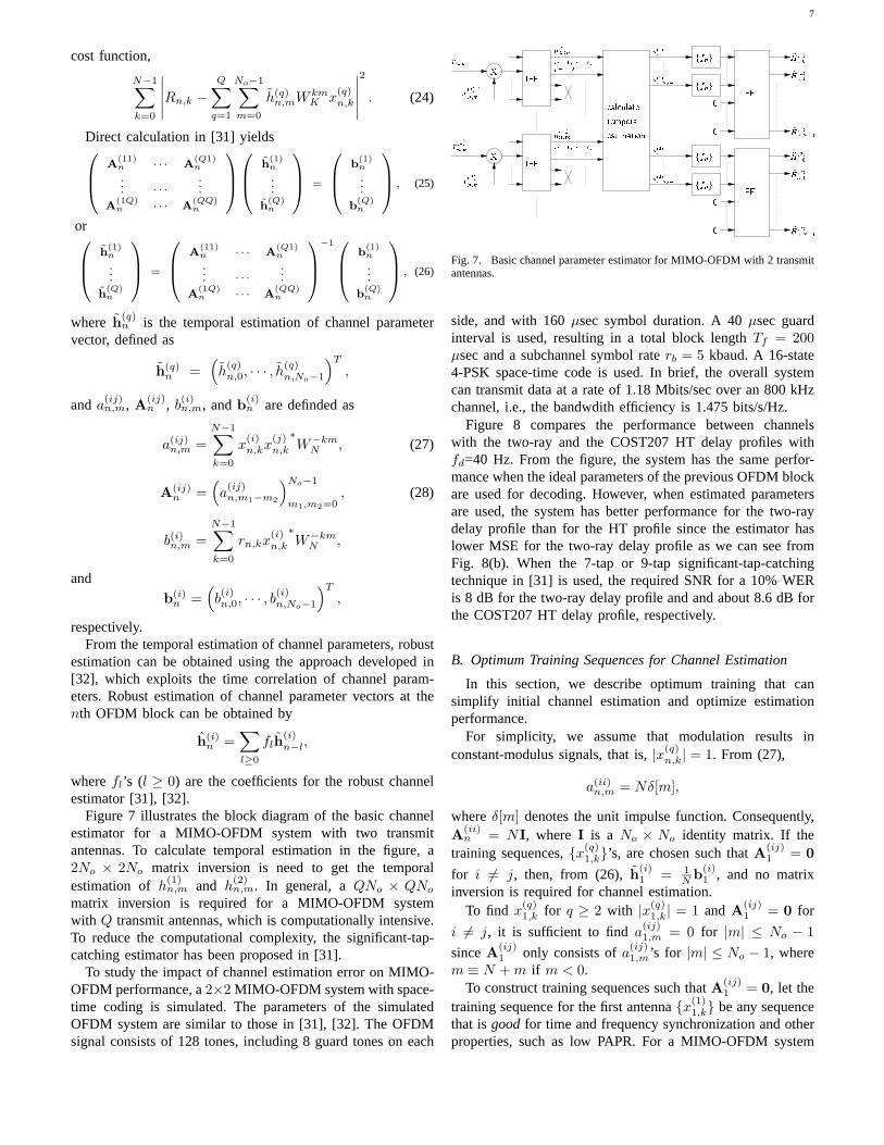
Figure 7 illustrates the block diagram of the basic channelestimator for a MIMO-OFDM system with two transmitantennas. To calculate temporal estimation in the figure, a2No × 2No matrix inversion is need to get the temporalestimation ofh(1)
n,m and h(2)n,m. In general, aQNo × QNo
matrix inversion is required for a MIMO-OFDM systemwith Q transmit antennas, which is computationally intensive.To reduce the computational complexity, the significant-tap-catching estimator has been proposed in [31].
To study the impact of channel estimation error on MIMO-OFDM performance, a2×2 MIMO-OFDM system with space-time coding is simulated. The parameters of the simulatedOFDM system are similar to those in [31], [32]. The OFDMsignal consists of 128 tones, including 8 guard tones on each
�����
���
���
����
����
�������
�
�������
�
����
����
����
����
�
�
�
� ����������
��������
��������
����������
��������
��������
��������
�����
������
��������
�����
������
�������
� � �� �
��������
� � �� � � � � �� � �
� � �� � � � � �� � �
��������
��� ��
��������
�������
�
Fig. 7. Basic channel parameter estimator for MIMO-OFDM with 2 transmitantennas.
side, and with 160µsec symbol duration. A 40µsec guardinterval is used, resulting in a total block lengthTf = 200µsec and a subchannel symbol raterb = 5 kbaud. A 16-state4-PSK space-time code is used. In brief, the overall systemcan transmit data at a rate of 1.18 Mbits/sec over an 800 kHzchannel, i.e., the bandwdith efficiency is 1.475 bits/s/Hz.
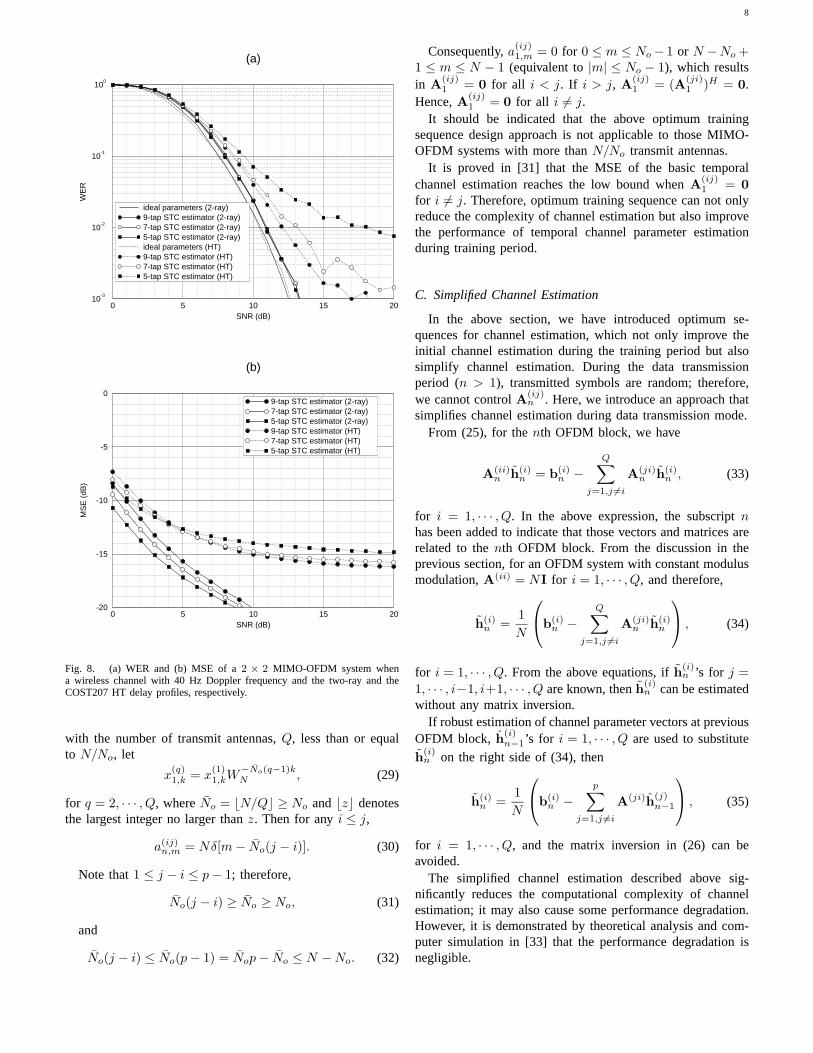
Figure 8 compares the performance between channelswith the two-ray and the COST207 HT delay profiles withfd=40 Hz. From the figure, the system has the same perfor-mance when the ideal parameters of the previous OFDM blockare used for decoding. However, when estimated parametersare used, the system has better performance for the two-raydelay profile than for the HT profile since the estimator haslower MSE for the two-ray delay profile as we can see fromFig. 8(b). When the 7-tap or 9-tap significant-tap-catchingtechnique in [31] is used, the required SNR for a 10% WERis 8 dB for the two-ray delay profile and and about 8.6 dB forthe COST207 HT delay profile, respectively.
B. Optimum Training Sequences for Channel Estimation
In this section, we describe optimum training that cansimplify initial channel estimation and optimize estimationperformance.
For simplicity, we assume that modulation results inconstant-modulus signals, that is,|x(q)
n,k| = 1. From (27),
a(ii)n,m = Nδ[m],
whereδ[m] denotes the unit impulse function. Consequently,A(ii)
n = NI, where I is a No × No identity matrix. If thetraining sequences,{x(q)
1,k}’s, are chosen such thatA(ij)1 = 0
for i �= j, then, from (26),h(i)1 = 1
N b(i)1 , and no matrix
inversion is required for channel estimation.To find x(q)
1,k for q ≥ 2 with |x(q)1,k| = 1 andA(ij)
1 = 0 for
i �= j, it is sufficient to finda(ij)1,m = 0 for |m| ≤ No − 1
sinceA(ij)1 only consists ofa(ij)
1,m’s for |m| ≤ No − 1, wherem ≡ N +m if m < 0.
To construct training sequences such thatA(ij)1 = 0, let the
training sequence for the first antenna{x(1)1,k} be any sequence
that isgood for time and frequency synchronization and otherproperties, such as low PAPR. For a MIMO-OFDM system
8
0 5 10 15 20SNR (dB)
10-3
10-2
10-1
100
WE
R
(a)
ideal parameters (2-ray)9-tap STC estimator (2-ray)7-tap STC estimator (2-ray)5-tap STC estimator (2-ray)ideal parameters (HT)9-tap STC estimator (HT)7-tap STC estimator (HT)5-tap STC estimator (HT)
0 5 10 15 20SNR (dB)
-20
-15
-10
-5
0
MS
E (
dB)
(b)
9-tap STC estimator (2-ray)7-tap STC estimator (2-ray)5-tap STC estimator (2-ray)9-tap STC estimator (HT)7-tap STC estimator (HT)5-tap STC estimator (HT)
Fig. 8. (a) WER and (b) MSE of a2 × 2 MIMO-OFDM system whena wireless channel with 40 Hz Doppler frequency and the two-ray and theCOST207 HT delay profiles, respectively.
with the number of transmit antennas,Q, less than or equalto N/No, let
x(q)1,k = x
(1)1,kW
−No(q−1)kN , (29)
for q = 2, · · · , Q, whereNo = �N/Q� ≥ No and�z� denotesthe largest integer no larger thanz. Then for anyi ≤ j,
a(ij)n,m = Nδ[m− No(j − i)]. (30)
Note that1 ≤ j − i ≤ p− 1; therefore,
No(j − i) ≥ No ≥ No, (31)
and
No(j − i) ≤ No(p− 1) = Nop− No ≤ N −No. (32)
Consequently,a(ij)1,m = 0 for 0 ≤ m ≤ No − 1 or N −No +
1 ≤ m ≤ N − 1 (equivalent to|m| ≤ No − 1), which resultsin A(ij)
1 = 0 for all i < j. If i > j, A(ij)1 = (A(ji)
1 )H = 0.Hence,A(ij)
1 = 0 for all i �= j.It should be indicated that the above optimum training
sequence design approach is not applicable to those MIMO-OFDM systems with more thanN/No transmit antennas.
It is proved in [31] that the MSE of the basic temporalchannel estimation reaches the low bound whenA(ij)
1 = 0for i �= j. Therefore, optimum training sequence can not onlyreduce the complexity of channel estimation but also improvethe performance of temporal channel parameter estimationduring training period.
C. Simplified Channel Estimation
In the above section, we have introduced optimum se-quences for channel estimation, which not only improve theinitial channel estimation during the training period but alsosimplify channel estimation. During the data transmissionperiod (n > 1), transmitted symbols are random; therefore,we cannot controlA(ij)
n . Here, we introduce an approach thatsimplifies channel estimation during data transmission mode.
From (25), for thenth OFDM block, we have
A(ii)n h(i)
n = b(i)n −
Q∑j=1,j �=i
A(ji)n h(i)
n , (33)
for i = 1, · · · , Q. In the above expression, the subscriptnhas been added to indicate that those vectors and matrices arerelated to thenth OFDM block. From the discussion in theprevious section, for an OFDM system with constant modulusmodulation,A(ii) = NI for i = 1, · · · , Q, and therefore,
h(i)n =
1N
b(i)
n −Q∑
j=1,j �=i
A(ji)n h(i)
n
, (34)
for i = 1, · · · , Q. From the above equations, ifh(i)n ’s for j =
1, · · · , i−1, i+1, · · · , Q are known, thenh(i)n can be estimated
without any matrix inversion.If robust estimation of channel parameter vectors at previous
OFDM block, h(i)n−1’s for i = 1, · · · , Q are used to substitute
h(i)n on the right side of (34), then
h(i)n =
1N
b(i)
n −p∑
j=1,j �=i
A(ji)h(j)n−1
, (35)
for i = 1, · · · , Q, and the matrix inversion in (26) can beavoided.
The simplified channel estimation described above sig-nificantly reduces the computational complexity of channelestimation; it may also cause some performance degradation.However, it is demonstrated by theoretical analysis and com-puter simulation in [33] that the performance degradation isnegligible.
9
D. Enhanced Channel Estimation
In [31], [33], Sections V-A, V-B, and V-C, we have in-troduced channel parameter estimators and optimum trainingsequences for OFDM with multiple transmit antennas. Further-more, for a MIMO-OFDM system where many independentchannels with the same delay profile are involved, the channeldelay profile can be more accurately estimated. By exploitingthe estimated channel delay profile, channel parameter estima-tion can be further improved.
From the above discussion, for thenth OFDM block,channel parameters corresponding to theqth transmit and thelth receive antenna pairs,h(ql)
n,m in (23), can be estimatedusing the correlation of channel parameters at different timesand frequencies. Withh(ql)
n,m, the estimatedh(ql)n,m, the channel
frequency response at thekth tone of thenth OFDM blockcan be reconstructed by
H(q,l)n,k =
No−1∑m=0
h(q,l)n,mW
kmN . (36)
The estimated channel parameter,h(q,l)n,m , can be decomposed
into the true channel parameter,h(q,l)n,m , and an estimation error,
e(q,l)n,m , that is
h(q,l)n,m = h(q,l)
n,m + e(q,l)n,m . (37)
From [33],e(q,l)n,m can be assumed to be Gaussian with zero-
mean and varianceσ2, and independent for differentq’s, l’s,n’s, or m’s. If the parameter estimation quality is measuredby means of the normalized MSE (NMSE), which is definedas
NMSE =E
∣∣∣H(q,l)n,k −H
(q,l)n,k
∣∣∣2E
∣∣∣H(q,l)n,k
∣∣∣2 ,
then it can be calculated directly that the NMSE for theestimation in (36) is
NMSEr = Noσ2, (38)
where we have used the assumption that
No−1∑l=0
E∣∣∣h(q,l)
n,m
∣∣∣2 =No−1∑l=0
σ2m = 1,
with σ2m = E
∣∣∣h(q,l)n,m
∣∣∣2.
If the channel’s delay profile, that is,σ2m’s for m =
0, · · · , No − 1, is known, and it can be used to reconstructthe channel frequency response fromh(q,l)
n,m , the NMSE ofH
(q,l)n,k can be significantly reduced. In this case, if theαm’s
are selected to minimize the NMSE of
H(q,l)n,k =
No−1∑m=0
αmh(q,l)n,mW
kmN , (39)
then it can be proven that the optimalαm is
αm =σ2
m
σ2m+σ2∑No−1
m′=0
σ4m′
σ2m′+σ2
(40)
and the NMSE is
NMSEo =σ2
∑No−1m=0
σ2m
σ2m+σ2∑No−1
m=0σ4
m
σ2m+σ2
. (41)
As indicated in [32], channel’s delay profile depends on theenvironment, and therefore, is usually unknown. However, forMIMO-OFDM systems, channels corresponding to differenttransmit or receive antennas should have approximately the
same delay profile. Therefore,σ2m = E
∣∣∣h(q,l)n,m
∣∣∣2 can beestimated by
σ2m =
1QL
Q∑q=1
L∑l=1
∣∣∣h(q,l)n,m
∣∣∣2 .With the estimatedσ2
m, enhanced channel frequency responsescan be reconstructed by (39).
0 5 10 15 20SNR (dB)
-20
-10
0
MS
E (
dB)
enhanced estimator for TU channelbasic estimator for TU channelenhanced estimator for HT channelbasic estimator for HT channel
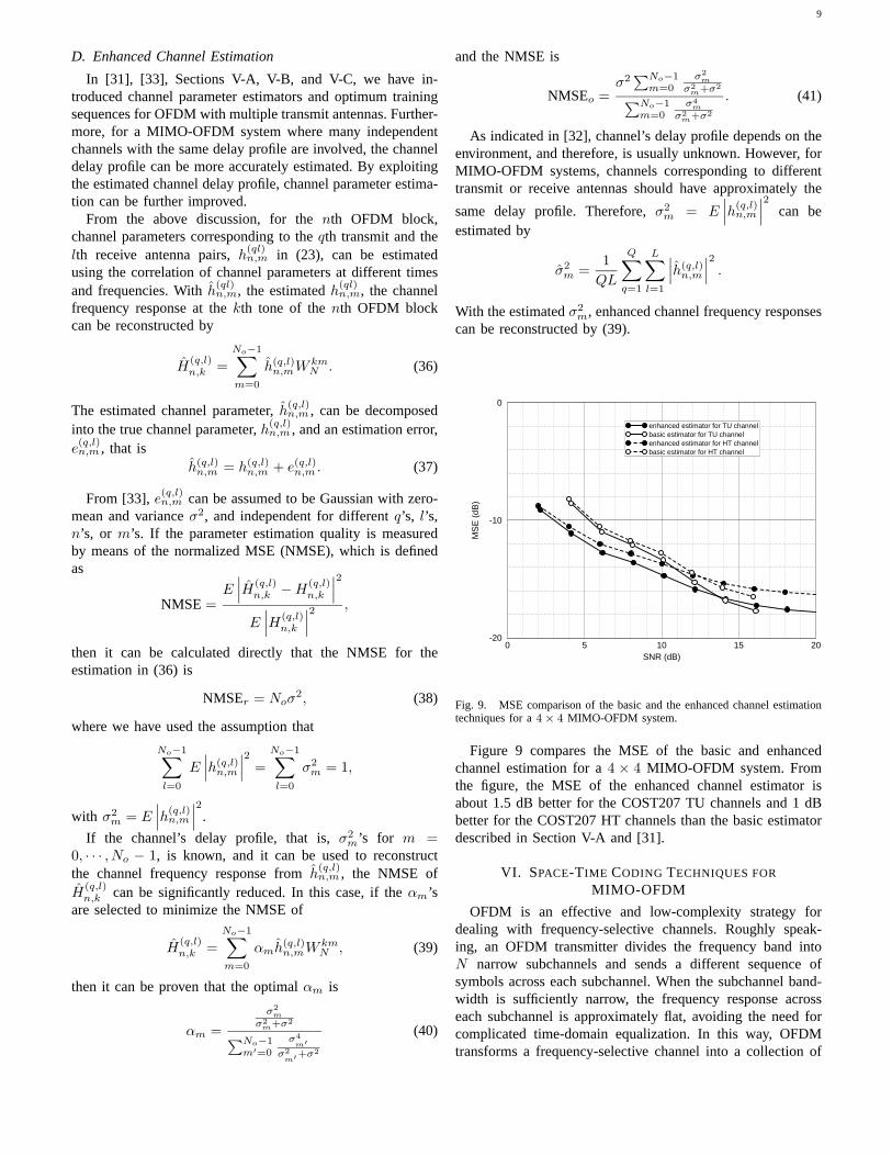
Fig. 9. MSE comparison of the basic and the enhanced channel estimationtechniques for a4 × 4 MIMO-OFDM system.
Figure 9 compares the MSE of the basic and enhancedchannel estimation for a4 × 4 MIMO-OFDM system. Fromthe figure, the MSE of the enhanced channel estimator isabout 1.5 dB better for the COST207 TU channels and 1 dBbetter for the COST207 HT channels than the basic estimatordescribed in Section V-A and [31].
VI. SPACE-TIME CODING TECHNIQUES FOR
MIMO-OFDM
OFDM is an effective and low-complexity strategy fordealing with frequency-selective channels. Roughly speak-ing, an OFDM transmitter divides the frequency band intoN narrow subchannels and sends a different sequence ofsymbols across each subchannel. When the subchannel band-width is sufficiently narrow, the frequency response acrosseach subchannel is approximately flat, avoiding the need forcomplicated time-domain equalization. In this way, OFDMtransforms a frequency-selective channel into a collection of
10
N separate flat-fading channels. In the same way, when anOFDM transmitter is used by each ofQ transmit antennas, andan OFDM front-end is used by each ofL receive antennas,a MIMO frequency-selective channel is transformed into acollection ofN flat-fading MIMO channels, one for each tone,with each having dimensionL×Q.
Traditional space-time codes were designed to extract spa-tial diversity from a flat-fading MIMO channel, and are notgenerally effective at extracting the additionalfrequency (ormultipath) diversity of a frequency-selective fading channel.Quantitatively, the maximum achievable diversity order is theproduct of the number of transmit antennas, the number ofreceiver antennas, and the number of resolvable propagationpaths (i.e., the channel impulse response length) [11][12].To achieve this full diversity requires that the informationsymbols be carefully spread over the tones as well as overthe transmitting antennas. Aspace-frequency code – or moregenerally, a space-time-frequency code – is a strategy formapping information symbols to antennas and tones as ameans for extracting both spatial and frequency diversity.
Space-frequency codes based directly on space-time codes(with time reinterpreted as frequency) have been proposed[10], [19], [50], [51], [52], but they fail to exploit the frequencydiversity of a frequency-selective fading MIMO channel [11].Guidelines for the design of full-diversity space-frequencycodes are given in [11]. A simple method for transformingany full-diversity space-time code into a full-diversity space-frequency code has recently been proposed, at the expense ofa reduced rate [49]. An example of a space-frequency codethat achieves full spatial and frequency diversity is given in[13]. The design of space-frequency and space-time-frequencycodes is currently an active area of research [11] [12] [13] [14][15] [16] [17] [18].
In the remainder of this section we highlight two approachesto space-time processing for MIMO-OFDM. The first is acombination of delay-diversity and OFDM known as multicar-rier delay-diversity modulation, while the second is a closed-loop system with channel knowledge at the transmitter.
A. Multicarrier Delay Diversity Modulation (MDDM)
Delay diversity was the first transmit diversity approachfor flat-fading MIMO channels [34], [35], [36], [37]. Mul-tiple transmit antennas send delayed copies of same signal,and maximum-likelihood sequence estimation [36], [38] ordecision-feedback equalization [39] is used at the receiverto estimate the transmitted sequence. The natural ability ofOFDM to mitigate frequency-selective fading makes delaydiversity an attractive option for MIMO-OFDM [20]. Forfrequency-selective fading channels, a cyclic delay-diversityapproach with OFDM is proposed in [21], a combinationknown asmulticarrier delay-diversity modulation (MDDM).MDDM is further investigated with space-time block codingin [22]. With proper coding, MDDM can achieve full spatialdiversity on flat fading channels [23]. Moreover, MDDMprovides a very flexible space-time coding approach for anynumber of transmit antennas, allowing the number of transmitantennas to be changed without changing the codes that areemployed, unlike STBC [23].
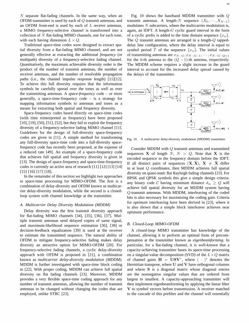
Fig. 10 shows the baseband MDDM transmitter withQtransmit antennas. A length-N sequence(X0, · · · ,XN−1)modulatesN subcarriers, where the multicarrier modulation is,again, an IDFT. A length-G cyclic guard interval in the formof a cyclic prefix is added to the time domain sequence{xn}.TheQ transmit antennas are arranged in a length-Q tapped-delay line configuration, where the delay interval is equal tosymbol periodT of the sequence{xn}. The initial valuesof transmitting antennas arexN−G, xN−G−1, · · · , xN−G−Q+1
for the 0-th antenna to the(Q− 1)-th antenna, respectively.The MDDM scheme requires a slight increase in the guardinterval to account for the increased delay spread caused bythe delays of the transmitter.
Fig. 10. A multicarrier delay-diversity modulation (MDDM) transmitter.
Consider MDDM withQ transmit antennas and transmittedsequencesX of length N , N > Q. Note that X is theencoded sequence in the frequency domain before the IDFT.If all distinct pairs of sequences(X, X), X �= X differin at leastQ coordinates, then MDDM achieves full spatialdiversity on quasi-static flat Rayleigh fading channels [23]. ForBPSK and QPSK symbols this give a simple design criteria:any binary codeC having minimum distancedm ≥ Q willachieve full spatial diversity for an MDDM system havingQ-transmit antennas. With MDDM, interleaving of the codedbits is also necessary for maximizing the coding gain. Criteriafor optimum interleaving have been derived in [23], where itis also shown that a simple block interleaver achieves nearoptimum performance.
B. Closed-Loop MIMO-OFDM
A closed-loop MIMO transmitter has knowledge of thechannel, allowing it to perform an optimal form of precom-pensation at the transmitter known aseigenbeamforming. Inparticular, for a flat-fading channel, it is well-known that acapacity-achieving transmitter bases its space-time processingon a singular-value decomposition (SVD) of theL×Q matrixof channel gainsH = USV∗, where ( · )∗ denotes theHermitian transpose, whereU andV have orthogonal columnsand whereS is a diagonal matrix whose diagonal entriesare the nonnegative singular values that are ordered fromlargest to smallest. A capacity-approaching transmitter willthen implement eigenbeamforming by applying the linear filterV to symbol vectors before transmission. A receiver matchedto the cascade of this prefilter and the channel will essentially
11
apply the filterU∗ to the received vector, which transforms theflat-fading channel into a bank of independent scalar channels.The problem has thus been reduced to one of communicationacross a bank of independent parallel scalar subchannels,where the subchannel gains are the nonnegative, nonincreasingsingular values of the channel.
Because OFDM reduces a frequency-selective channel toa collection of flat-fading MIMO channels, a closed-loopMIMO-OFDM system can use eigenbeamforming on a tone-by-tone basis to transform a frequency-selecting MIMO chan-nel into a collection ofMN parallel subchannels [9], whereM = min{Q,L} is the minimum number of antennas at eachend andN is the number of OFDM tones. A MIMO-OFDMsystem with eigenbeamforming is illustrated in Fig. 11-a forthe special case of two transmit and two receive antennas. Theprefilters{Vn} and postfilters{U∗
n} are related to the 2-by-2 matrix of channel gains for then-th toneHn by the SVDHn = UnSnV∗
n. The permuterπ at the transmitter is a simplerow-column interleaver of dimensionN×2. The entire systemof Fig. 11-a reduces to the bank of scalar channels shown inFig. 11-b, wheresi,j denotes thei-th singular value for thej-th tone.
Fig. 11. A combination of eigenbeamforming and OFDM transforms aclosed-loop frequency-selective fading channel (a) into a bank of scalarchannels (b), each with independent noise.
Ideally, information bits (constellation size) and symbolenergy would be allocated to theMN subchannels of Fig. 11-b so as to minimize the overall SNR requirement, subjectto a target bit rate. (Alternatively, the bits and energy couldbe allocated so as to maximize the bit rate, subject to atarget energy constraint.) Unfortunately, the complexity of anexhaustive search for the bit-allocation is prohibitive whenthe number of subchannels is large. In a practical MIMO-OFDM application, the number of subchannelsMN can bevery large, which motivates a search for low-complexity bit-allocation strategies with near-optimal performance.
A simple and effective way to reduce complexity is to
impose aflat-frequency constraint, where each tone is re-stricted to have the same bit budget [40]. We now illustratethat the penalty due to this constraint can be small. LetBdenote the total bit budget for each OFDM signaling interval.Without the flat-frequency constraint, and without constrainingthe symbols to a discrete alphabet, the optimal rateri,j for thei-th spatial channel (singular value) and thej-th tone is foundby waterpouring over both space and frequency, yielding
ri,j = {log2(λs2i,j)}+,
where{x}+ = max{0, x}, and whereλ ensures that the totalbit budget is met,
∑i,j ri,j = B. On the other hand, if we
enforce the flat-frequency constraint, the constrained optimalsolution is
ri,j = {log2(µjs2i,j)}+,
whereµj ensures that∑
i ri,j = B/N for eachj = 1, ...N .Sinceµj is calculated anew each tone, this amounts to water-pouring over space but not frequency. In either case, theaverage required SNR is given by:
E/N0 = E[M∑i=1
N∑j=1
2ri,j − 1s2i,j
],
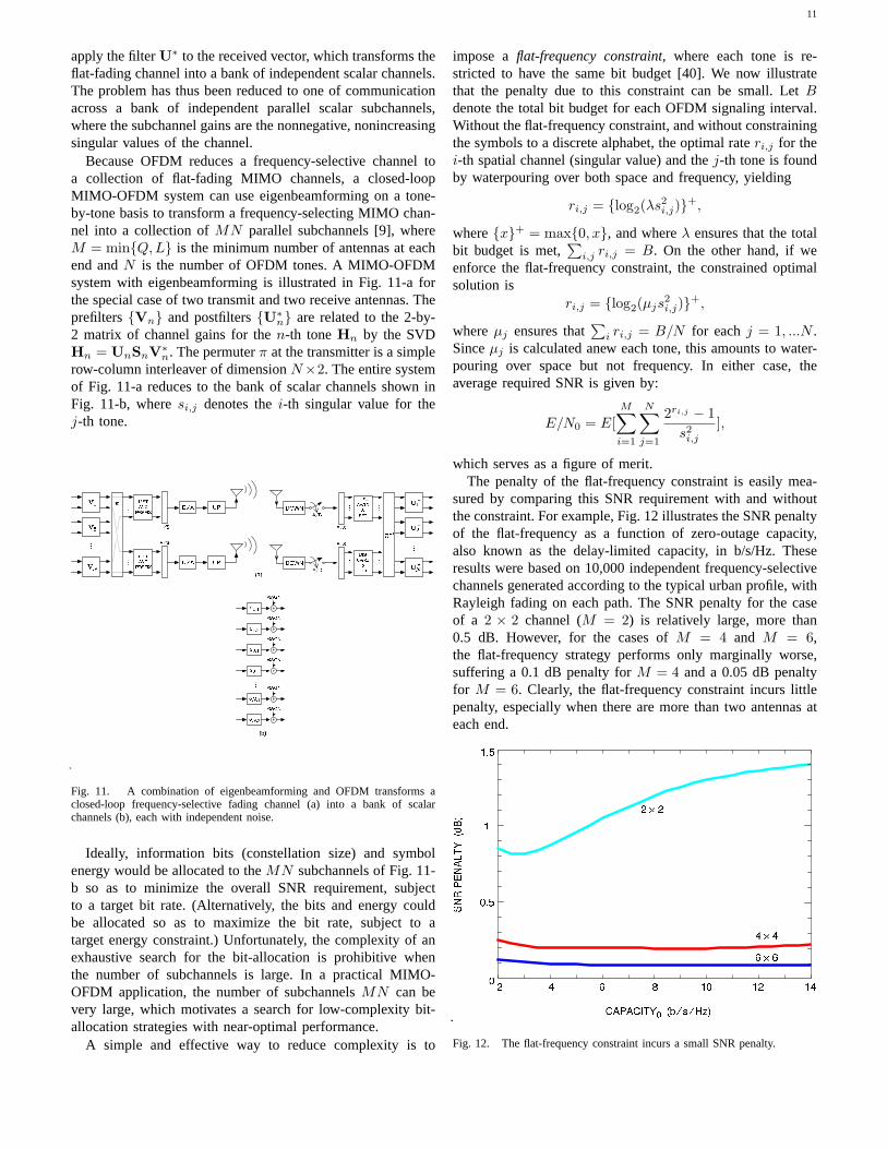
which serves as a figure of merit.The penalty of the flat-frequency constraint is easily mea-
sured by comparing this SNR requirement with and withoutthe constraint. For example, Fig. 12 illustrates the SNR penaltyof the flat-frequency as a function of zero-outage capacity,also known as the delay-limited capacity, in b/s/Hz. Theseresults were based on 10,000 independent frequency-selectivechannels generated according to the typical urban profile, withRayleigh fading on each path. The SNR penalty for the caseof a 2 × 2 channel (M = 2) is relatively large, more than0.5 dB. However, for the cases ofM = 4 and M = 6,the flat-frequency strategy performs only marginally worse,suffering a 0.1 dB penalty forM = 4 and a 0.05 dB penaltyfor M = 6. Clearly, the flat-frequency constraint incurs littlepenalty, especially when there are more than two antennas ateach end.
Fig. 12. The flat-frequency constraint incurs a small SNR penalty.
12
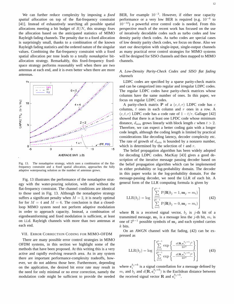
We can further reduce complexity by imposing afixedspatial allocation on top of the flat-frequency constraint[41]. Instead of exhaustively searching all possible spatialallocations meeting a bit budget ofB/N , this strategy fixesthe allocation based on the anticipated statistics of MIMORayleigh fading channels. The penalty due to a fixed allocationis surprisingly small, thanks to a combination of the knownRayleigh fading statistics and the ordered nature of the singularvalues. Combining the flat-frequency constraint with a fixedspatial allocation per tone leads to a totallynonadaptive bit-allocation strategy. Remarkably, this fixed-frequency fixed-space strategy performs reasonably well when there are twoantennas at each end, and it is even better when there are moreantennas.
Fig. 13. The nonadaptive strategy, which uses a combination of the flat-frequency constraint and a fixed spatial allocation, approaches the fullyadaptive waterpouring solution as the number of antennas grows.
Fig. 13 illustrates the performance of the nonadaptive strat-egy with the water-pouring solution, with and without theflat-frequency constraint. The channel conditions are identicalto those used in Fig. 13. Although the nonadaptive strategysuffers a significant penalty whenM = 2, it is nearly optimalfor for M = 4 andM = 6. The conclusion is that a closed-loop MIMO system need not perform adaptive modulationin order to approach capacity. Instead, a combination ofeigenbeamforming and fixed modulation is sufficient, at leaston i.i.d. Rayleigh channels with more than two antennas ateach end.
VII. E RRORCORRECTIONCODING FORMIMO-OFDM
There are many possible error control strategies in MIMOOFDM systems, in this section we highlight some of themethods that have been proposed. At this writing this is a veryactive and rapidly evolving research area. As in any systemthere are important performance-complexity tradeoffs, how-ever, we do not address those here. Furthermore, dependingon the application, the desired bit error rate may result inthe need for only minimal or no error correction, namely themodulation code might be sufficient to provide the needed
BER, for example10−3. However, if either near capacityperformance or a very low BER is required (e.g.10−6 to10−12) a powerful error control code is needed. From thisperspective much of the recent work has focused on the useof iteratively decodable codes such as turbo codes and lowdensity parity check codes. As turbo codes are special casesof low density parity check codes, we focus on those. Also westart our description with single-input, single-output channelsas many practical error control strategies for MIMO systemswill be designed for SISO channels and then mapped to MIMOchannels.
A. Low-Density Parity-Check Codes and SISO flat fadingchannels
LDPC codes are specified by a sparse parity-check matrixand can be categorized into regular and irregular LDPC codes.The regular LDPC codes have parity-check matrices whosecolumns have the same number of ones. In this paper, wefocus on regular LDPC codes.
A parity-check matrixP of a (c, t, r) LDPC code hasccolumns, t ones in each column andr ones in a row. A(c, t, r) LDPC code has a code rate of1 − t/r. Gallager [42]showed that there is at least one LPDC code whose minimumdistance,dmin grows linearly with block lengthc whent > 2.Therefore, we can expect a better coding gain with a longercode length, although the coding length is limited by practicalconsiderations like decoding latency, decoder complexity etc.The rate of growth ofdmin is bounded by a nonzero number,which is determined by the selection oft andr.
The belief propagation algorithm has been widely adoptedfor decoding LDPC codes. MacKay [43] gives a good de-scription of the iterative message passing decoder based onthe belief propagation algorithm which can be implementedin either probability or log-probability domain. The decoderin this paper works in the log-probability domain. For themessage-passing decoder, we need the LLR of each bit. Ageneral form of the LLR computing formula is given by
LLR(bj) = log
2k−1∑i=1
P(R|bj = 1,mj = mi)
2k−1∑i=1
P(R|bj = 0,mj = mi)
(42)
where R is a received signal vector,bj is j-th bit of atransmitted message,mj is a message less thej-th bit, mi isone of2k−1 possible symbols ofmj and each symbol carriesk bits.
On an AWGN channel with flat fading, (42) can be ex-pressed as
LLR(bj) = log
2k−1∑i=1
exp{−d(R,c
bj=1i
)2
2σ2
}2k−1∑i=1
exp{−d(R,c
bj=0i
)2
2σ2
} (43)
wherecbj=bi is a signal constellation for a message defined by
mi andbj andd(R, cbj=bi ) is the Euclidean distance between
the received signal vectorR andcbj=bi .
13
To prevent possible underflow or overflow, the equation canbe modified to a more applicable form as
LLR(bj) = (d0min(j))2−(d1
min(j))2
2σ2
+ log
1 +
2k−1∑i=1,i�=l1
exp{−d(R,c
bj=1i
)2−(d1min(j))2
2σ2
}
− log
1 +
2k−1∑i=1,i�=l0
exp{−d(R,c
bj=0i
)2−(d0min(j))2
2σ2
}
(44)
wheredbmin(j) = d(R, cbj=b
lb) = min
1≤i≤2k−1d(R, cbj=b
i ) andb is
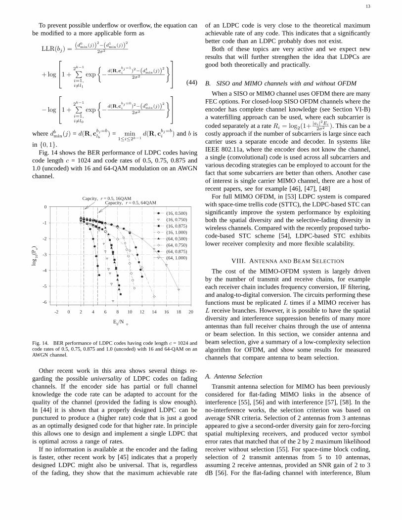
in {0, 1}.Fig. 14 shows the BER performance of LDPC codes having
code lengthc = 1024 and code rates of 0.5, 0.75, 0.875 and1.0 (uncoded) with 16 and 64-QAM modulation on an AWGNchannel.
Eb/N o
-2 0 2 4 6 8 10 12 14 16 18 20
log
10(P
e)
-6
-5
-4
-3
-2
-1
0(16, 0.500)(16, 0.750)(16, 0.875)(16, 1.000)(64, 0.500)(64, 0.750)(64, 0.875)(64, 1.000)
Capcity, r = 0.5, 16QAMCapacity, r = 0.5, 64QAM
Fig. 14. BER performance of LDPC codes having code lengthc = 1024 andcode rates of 0.5, 0.75, 0.875 and 1.0 (uncoded) with 16 and 64-QAM on anAWGN channel.
Other recent work in this area shows several things re-garding the possibleuniversality of LDPC codes on fadingchannels. If the encoder side has partial or full channelknowledge the code rate can be adapted to account for thequality of the channel (provided the fading is slow enough).In [44] it is shown that a properly designed LDPC can bepunctured to produce a (higher rate) code that is just a goodas an optimally designed code for that higher rate. In principlethis allows one to design and implement a single LDPC thatis optimal across a range of rates.
If no information is available at the encoder and the fadingis faster, other recent work by [45] indicates that a properlydesigned LDPC might also be universal. That is, regardlessof the fading, they show that the maximum achievable rate
of an LDPC code is very close to the theoretical maximumachievable rate of any code. This indicates that a significantlybetter code than an LDPC probably does not exist.
Both of these topics are very active and we expect newresults that will further strengthen the idea that LDPCs aregood both theoretically and practically.
B. SISO and MIMO channels with and without OFDM
When a SISO or MIMO channel uses OFDM there are manyFEC options. For closed-loop SISO OFDM channels where theencoder has complete channel knowledge (see Section VI-B)a waterfilling approach can be used, where each subcarrier iscoded separately at a rateRi = log2(1+ |ai|2Ei
2σ2 ). This can be acostly approach if the number of subcarriers is large since eachcarrier uses a separate encode and decoder. In systems likeIEEE 802.11a, where the encoder does not know the channel,a single (convolutional) code is used across all subcarriers andvarious decoding strategies can be employed to account for thefact that some subcarriers are better than others. Another caseof interest is single carrier MIMO channel, there are a host ofrecent papers, see for example [46], [47], [48]
For full MIMO OFDM, in [53] LDPC system is comparedwith space-time trellis code (STTC), the LDPC-based STC cansignificantly improve the system performance by exploitingboth the spatial diversity and the selective-fading diversity inwireless channels. Compared with the recently proposed turbo-code-based STC scheme [54], LDPC-based STC exhibitslower receiver complexity and more flexible scalability.
VIII. A NTENNA AND BEAM SELECTION
The cost of the MIMO-OFDM system is largely drivenby the number of transmit and receive chains, for exampleeach receiver chain includes frequency conversion, IF filtering,and analog-to-digital conversion. The circuits performing thesefunctions must be replicatedL times if a MIMO receiver hasL receive branches. However, it is possible to have the spatialdiversity and interference suppression benefits of many moreantennas than full receiver chains through the use of antennaor beam selection. In this section, we consider antenna andbeam selection, give a summary of a low-complexity selectionalgorithm for OFDM, and show some results for measuredchannels that compare antenna to beam selection.
A. Antenna Selection
Transmit antenna selection for MIMO has been previouslyconsidered for flat-fading MIMO links in the absence ofinterference [55], [56] and with interference [57], [58]. In theno-interference works, the selection criterion was based onaverage SNR criteria. Selection of 2 antennas from 3 antennasappeared to give a second-order diversity gain for zero-forcingspatial multiplexing receivers, and produced vector symbolerror rates that matched that of the 2 by 2 maximum likelihoodreceiver without selection [55]. For space-time block coding,selection of 2 transmit antennas from 5 to 10 antennas,assuming 2 receive antennas, provided an SNR gain of 2 to 3dB [56]. For the flat-fading channel with interference, Blum
14
and Winters [57] show about a 7 dB improvement for 8-select-2 diversity at both ends of the link, assuming one or twointerference data streams and simulated iid MIMO channels.
The MIMO selection diversity gain comes with a price: theswitch that performs the antenna selection requires a non-trivial design and has a non-negligible insertion loss [59].For example the 8-select-2 switch in [59] has an insertionloss of 3.15 dB. In a transmitter, the insertion loss reducesthe radiated power. In a receiver, the insertion loss degradesthe SNR. The degradation can be made negligible by placinglow-noise-amplifiers between the antenna elements and theswitch. However, this addition can add significant expenseto the receiver. On the other hand, the degradation in SNRmay not be important if the receiver performance is limitedby interference.
The gain from antenna selection for OFDM-MIMO may notbe as large as it is for the flat-fading channel because the bestselection of elements is likely to change with frequency. Whilesubcarrier-dependent antenna selection is considered in [60],we do not consider this here, since our goal is for the solutionto have a certain limited number of transmit and receive chains.
B. Beam Selection
An alternative selection approach for OFDM-MIMO is toselect beams instead of selecting antennas. Fig. 15 shows thearchitectures when4 × 2 (a) antenna selection and (b) beamselection are used at both ends of the link. Both architec-tures require the4 × 2 switch. Beam selection is motivatedby the observation that multipath angles are often clustered[61], [62]. The cluster angles are not expected to be veryfrequency-dependent, so the best selection of beams shouldnot change much with frequency. Therefore, if the beamwidthcan be matched to the cluster width, there should be an SNRadvantage in the absence of interference [63] and a signal-to-interference (SIR) advantage with interference. Moreover, ana-log beamforming circuits, such as the Butler matrix [64], areinexpensive compared to the switch at microwave frequenciesbecause they can be implemented in stripline [65]. Therefore,the percentage increase in cost to have beam selection shouldsmall. Like the switch, the beamformer has an insertion loss(2.26 dB for the 8-beam Butler matrix is in [65]) so its effectsmust be more than overcome to justify its use. Two-beamselection for array receivers over simulated clustered indoorchannels have indicated that four 8-element linear arrays,placed end-to-end in a square configuration to provide 360degrees azimuth coverage, yield an almost 6 dB SNR improve-ment compared to two fixed omnidirectional antennas whenthe two beams are processed by a joint decision-feedbackequalizer [66]. When the same beam-selection configurationis simulated for Space-time block coded OFDM, an SNRimprovement of approximately 5 dB is obtained withoutinterference, and an SIR improvement of more than 16 dBis obtained with interference [67].
C. A Selection Algorithm
In order to select receive beams with good SIR, but with aconstraint on the number of full receiver chains, a two-metric,
iterative selection algorithm has been proposed [67]. Thisalgorithm assumes a single-input-multiple-output channel andit applies to both antenna and beam selection. It is describedbelow for the case of two receiver chains, however, it easilyextends to an arbitrary number of receiver chains.
The first metric, RSSI, is measured for all beams by analogdetectors, while the second metric, the peak-to-trough ratio(PTR) [68], is based on a sliding correlation of the receivedpreamble with one stored OFDM preamble symbol and iscomputed in the digital signal processor (DSP) prior to fullOFDM synchronization. We note that the second metric in[67] is bit-error-rate. The PTR, to be defined below, is judgedto be a more practical and readily available second metric.The two beams having the highest RSSI are connected to thereceiver chains by the RF switch. Then, the PTR values arechecked for the two selected beams. If the PTR value for abeam is less than a threshold (which can be set based on thereal system’s requirement), we conclude that this beam hastoo much interference; then we check the beam with the next-highest RSSI until we find a PTR value that is higher than thethreshold.
To get the PTR value, we use the following equation
Rx(m) =
∣∣∣∑N1n=0 rx(n+m)tx
∗(n)∣∣∣∣∣∣∑N1
n=0 rx(n+m)rx∗(n+m)∣∣∣ , (45)
m = 0, 1, 2....N2
where rx is the received short training sequence which in-cludes noise and interference, andtx is the original one-period-long training sequence. N1 is the length of one periodof the training sequence. N2 is the length of the wholeshort training sequence plus one period length.Rx(m) is thenormalized cross-correlation function. If the received signalincludes limited noise and interference,Rx(m) will haveN2/N1-1 peaks. Then each peak and some points on each sideof it are removed. The remainder depends on the correlationof the training sequence with the noise and interference. Thesecond metric is computed as
PTR =< (magnitude of the peaks)2 >
< (magnitude of the remainder)2 >(46)
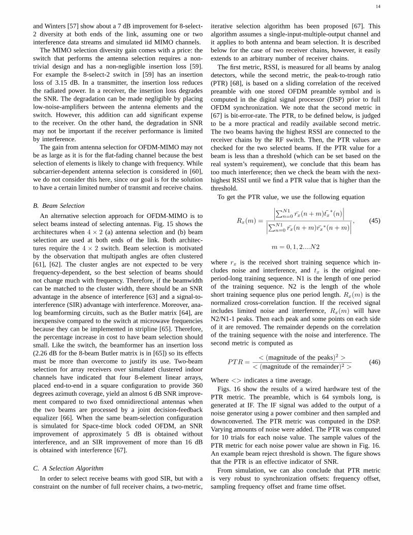
Where<> indicates a time average.Figs. 16 show the results of a wired hardware test of the
PTR metric. The preamble, which is 64 symbols long, isgenerated at IF. The IF signal was added to the output of anoise generator using a power combiner and then sampled anddownconverted. The PTR metric was computed in the DSP.Varying amounts of noise were added. The PTR was computedfor 10 trials for each noise value. The sample values of thePTR metric for each noise power value are shown in Fig. 16.An example beam reject threshold is shown. The figure showsthat the PTR is an effective indicator of SNR.
From simulation, we can also conclude that PTR metricis very robust to synchronization offsets: frequency offset,sampling frequency offset and frame time offset.
15
H
BT
JT
BR
JR
Selection
Switch
Butler
Matrix
Butler
Matrix
Selection
Switch
H
JT
JR
Selection
Switch
Selection
Switch
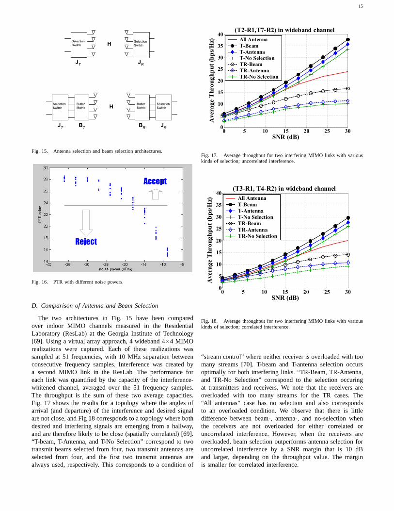
Fig. 15. Antenna selection and beam selection architectures.
Reject
Accept
Fig. 16. PTR with different noise powers.
D. Comparison of Antenna and Beam Selection
The two architectures in Fig. 15 have been comparedover indoor MIMO channels measured in the ResidentialLaboratory (ResLab) at the Georgia Institute of Technology[69]. Using a virtual array approach, 4 wideband 4×4 MIMOrealizations were captured. Each of these realizations wassampled at 51 frequencies, with 10 MHz separation betweenconsecutive frequency samples. Interference was created bya second MIMO link in the ResLab. The performance foreach link was quantified by the capacity of the interference-whitened channel, averaged over the 51 frequency samples.The throughput is the sum of these two average capacities.Fig. 17 shows the results for a topology where the angles ofarrival (and departure) of the interference and desired signalare not close, and Fig 18 corresponds to a topology where bothdesired and interfering signals are emerging from a hallway,and are therefore likely to be close (spatially correlated) [69].“T-beam, T-Antenna, and T-No Selection” correspond to twotransmit beams selected from four, two transmit antennas areselected from four, and the first two transmit antennas arealways used, respectively. This corresponds to a condition of
0 5 10 15 20 25 300
5
10
15
20
25
30
35
40
SNR (dB)
Avera
ge
Th
ro
ug
hp
ut
(bp
s/H
z)
(T2-R1,T7-R2) in wideband channel
All Antenna
T-Beam
T-Antenna
T-No Selection
TR-Beam
TR-Antenna
TR-No Selection
Fig. 17. Average throughput for two interfering MIMO links with variouskinds of selection; uncorrelated interference.
0 5 10 15 20 25 300
5
10
15
20
25
30
35
40
SNR (dB)
Avera
ge
Th
ro
ug
hp
ut
(bp
s/H
z)
(T3-R1, T4-R2) in wideband channel
All Antenna
T-Beam
T-Antenna
T-No Selection
TR-Beam
TR-Antenna
TR-No Selection
Fig. 18. Average throughput for two interfering MIMO links with variouskinds of selection; correlated interference.
“stream control” where neither receiver is overloaded with toomany streams [70]. T-beam and T-antenna selection occursoptimally for both interfering links. “TR-Beam, TR-Antenna,and TR-No Selection” correspond to the selection occuringat transmitters and receivers. We note that the receivers areoverloaded with too many streams for the TR cases. The“All antennas” case has no selection and also correspondsto an overloaded condition. We observe that there is littledifference between beam-, antenna-, and no-selection whenthe receivers are not overloaded for either correlated oruncorrelated interference. However, when the receivers areoverloaded, beam selection outperforms antenna selection foruncorrelated interference by a SNR margin that is 10 dBand larger, depending on the throughput value. The marginis smaller for correlated interference.
16
IX. M EDIUM ACCESSCONTROL
Although not the focus of this paper, MAC protocolsare essential for effective broadband wireless access. MACprotocols for OFDM can be based on time division multi-ple access (TDMA), where all the OFDM sub-carriers areused at once. Such protocols are used in IEEE802.11a andIEEE802.16a for example. An alternative is to used OFDMAor clustered OFDM, where each connection uses a subset ofthe OFDM sub-carriers. Such an approach is used in someoperating modes of IEEE802.16a. MAC protocols generallymust support hundreds of end-user terminals that demand amixture of services ranging from traditional voice and data,internet protocol (IP) connectivity, multimedia and real timeapplications such as voice over IP (VoIP). The support ofthese services requires a MAC protocol that handles bothcontinuous and bursty traffic with quality of service (QoS)guarantees that depend on the application. The issues oftransport efficiency are addressed at the interface betweenthe MAC and PHY layers, and the actual throughput that isachieved is highly dependent on the choice of MAC protocol.For example, the MAC adjust PHY layer parameters such asthe type of modulation and coding employed to meet QoSand link availability requirements. Addition information ontypical MAC related issues are available in a variety of sourcesincluding the IEEE802.16a standard [2].
X. SOFTWARE RADIO IMPLEMENTATION
The proliferation of high-performance DSP cores, FPGAsand ASICs - as well as the current trend towards System-on-a-Chip (SoC) integration - are bringing the software radioparadigm closer to practical realization. While advances inthese key technology areas - and other areas such as widebandA/Ds, low-power circuit technology and wideband amplifiers- are critical in the evolution of software radio, technologytoday allows one to begin to discover and appreciate thegreat promise that software radio holds. Current trends inthe wireless telecommunications industry are steering towardsadvanced applications requiring wider bandwidth, which willplace increasing processing loads upon future SDR implemen-tation architectures.
Faculty at Georgia Tech are collaborating to develop a highbandwidth, high data-rate wireless gateway using advancedtechnologies including software radio, smart antennas, MIMO-OFDM, advanced FECs, and higher layers that support qualityof service. A key component in the research is the imple-mentation of the techniques in a programmable testbed at theGT Software Radio Laboratory. In this paper, we focus on adescription of the physical layer and on the implementation ofMIMO-OFDM in the testbed.
In the first part of this section, we describe the designand performance of the software-radio testbed, which wasdeveloped using commercial components to implement pro-grammable transceivers for wireless communications. Thesystem provides a useful vantage point for empirical explo-ration of issues related to software radio implementation. Wedescribe the major hardware components, the algorithm flowthrough the system, and the implementation performance forMIMO-OFDM.
A. Software Radio Overview
Software radio, as discussed in this section, refers to atransceiver with radio receive and/or transmit functions definedin software. Given the current state of technology, software-defined radio functions are typically employed in the in-termediate frequency (IF) and baseband subsystems. Often,software defined functions are supported with complementarytechnologies, including programmable devices, such as FieldProgrammable Gate Arrays (FPGAs), which can performcertain functions - e.g., down-conversion, FFTs and FECdecoding - more efficiently than software-defined functionsin processing cores. In future Software Defined Radio (SDR),software defined functions and programmable features wouldbe reconfigurable either through over-the-air commands or viaadaptive circuitry allowing a mobile transceiver to seamlesslyreconfigure itself based on the electromagnetic environment orother cues available to a transceiver [71].
The programmable functions and features of the testbedare not entirely mature, but do provide a reasonable degreeof programming flexibility. As might be expected, the mostflexible portions for defining radio functions in our systemare those implemented in baseband digital signal processors(DSPs). Programming flexibility of the system diminishes asone moves from baseband operations (with DSP and FPGAprocessing) towards the RF end. In the IF section, the systemcan employ programmable digital down-converters, DSPs andleverage FPGAs to implement algorithms. The system is leastflexible in the radio frequency (RF) front end of the system,where the RF equipment offers programmable control oftuning frequency and input and output signal attenuations.Following conventional wisdom, the programmable hardwareis more easily reconfigured over a limited range of operationbut does not offer the same flexibility that software definedfunctions afford. The advantage of software defined functions,however, is balanced by challenges presented by real-timeimplementation issues: the engineer is faced with the task ofdefining and then implementing algorithms for real-time oper-ation with constraints imposed by buffering, data input/output(I/O) throughput, bus architectures and capacity, processingspeeds, and memory size and access times.
B. Testbed Architecture
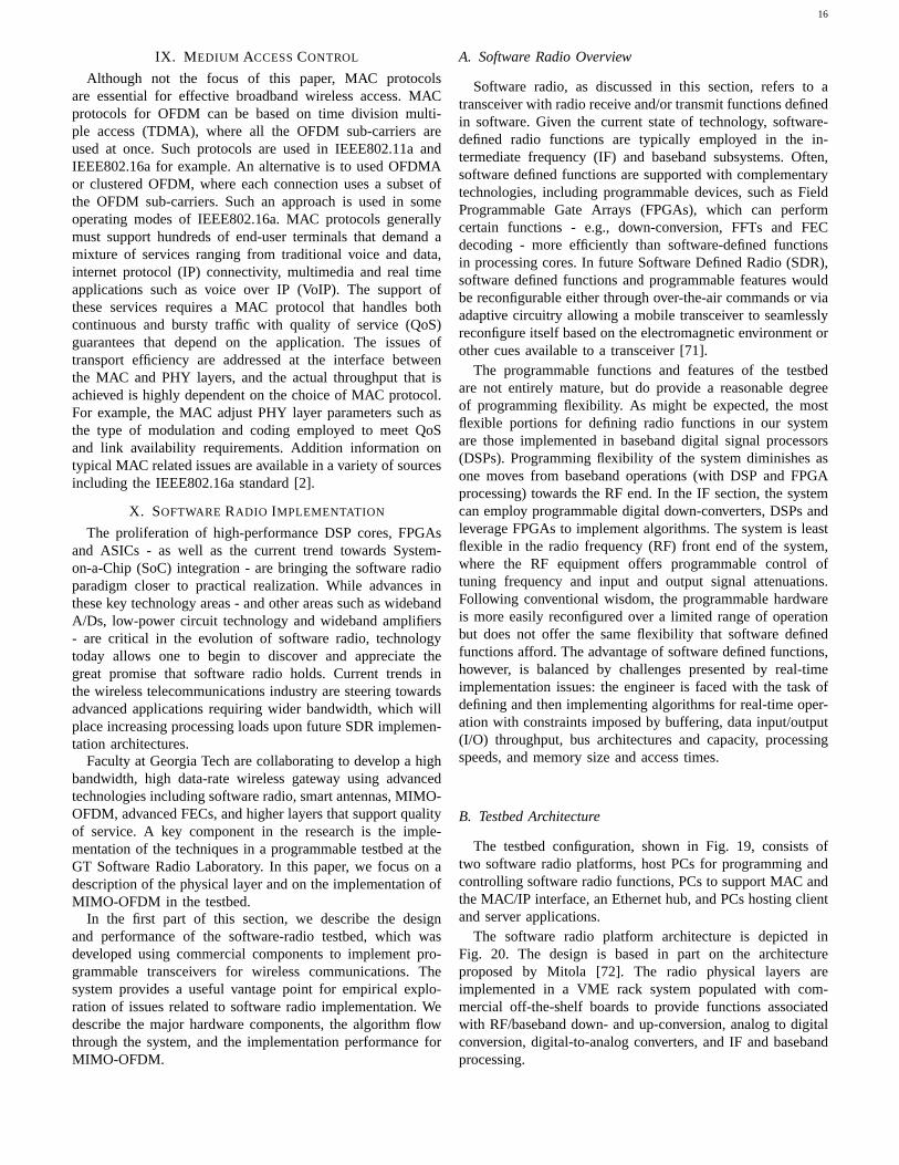
The testbed configuration, shown in Fig. 19, consists oftwo software radio platforms, host PCs for programming andcontrolling software radio functions, PCs to support MAC andthe MAC/IP interface, an Ethernet hub, and PCs hosting clientand server applications.
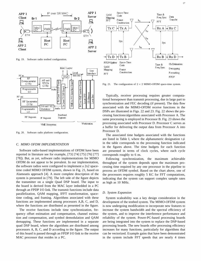
The software radio platform architecture is depicted inFig. 20. The design is based in part on the architectureproposed by Mitola [72]. The radio physical layers areimplemented in a VME rack system populated with com-mercial off-the-shelf boards to provide functions associatedwith RF/baseband down- and up-conversion, analog to digitalconversion, digital-to-analog converters, and IF and basebandprocessing.
17
Fig. 19. Software radio testbed configuration.
Fig. 20. Software radio platform configuration.
C. MIMO OFDM IMPLEMENTATION
Software radio-based implementations of OFDM have beenreported in literature see for example, [73] [74] [75] [76] [77][78]). But, as yet, software radio implementations for MIMOOFDM do not appear to be prevalent. In our implementation,the software radios were configured to implement a 2x2 space-time coded MIMO OFDM system, shown in Fig. 21, based onAlamoutis approach [4]. A more complete description of thesystem is presented in [79]. The left side of the figure depictsthe transmitter on a single Quad DSP board. The input tothe board is derived from the MAC layer imbedded in a PCthrough an FPDP I/O link. The transmit functions include dataparallelization, QAM mapping, IFFT transformation, space-time coding, and framing. Algorithms associated with thesefunctions are implemented among processors A,B, C, and D,where the functions are distributed as presented in the figure.
The receive functions include time synchronization, fre-quency offset estimation and compensation, channel estima-tion and compensation, and symbol demodulation and QAMdemapping. These functions are implemented in a separatequad DSP board, where the algorithms are distributed amongprocessors A, B, C, and D according to the figure. The outputof this board is passed through an FPDP I/O link to the receiveMAC processor that resides in a PC.
Fig. 21. The configuration of2 × 2 MIMO-OFDM space-time system.
Typically, receiver processing requires greater computa-tional horsepower than transmit processing, due in large part tosynchronization and FEC decoding (if present). The data flowassociated with the MIMO-OFDM receive functions in theDSPs are illustrated in Figs. 22 and 23. Fig. 22 shows the pro-cessing functions/algorithms associated with Processor A. Thesame processing is employed in Processor B. Fig. 23 shows theprocessing associated with Processor D. Processor C serves asa buffer for delivering the output data from Processor A intoProcessor D.
The associated time budgets associated with the functionsare listed in Table I, where the alphanumeric designationt#in the table corresponds to the processing function indicatedin the figures above. The time budgets for each functionare presented in terms of clock cycles, where each cyclecorresponds roughly to 6 ns.
Following synchronization, the maximum achievablethroughput of the system depends upon the maximum pro-cessing time required by any one processor in the pipeline toprocess an OFDM symbol. Based on the chart above, one ofthe processors requires roughly 5 KC for FFT computations,indicating that the system can support complex sample ratesas high as 10 MHz.
D. System Expansion
System scaleability was a key design consideration in thedevelopment of the testbed system. The MIMO-OFDM systemis now undergoing modification to incorporate new features toincrease the system bandwidth and the spectral efficiency ofthe system, and to improve the interference performance andreliability of the system. Power-PC-based processing boardsare being integrated into the system to replace the DSP-basedprocessing boards. The new boards offer processing efficiencyincreases for many functions, particularly for algorithms thatcan be vectorized. Example gains that have been demonstratedin the system include FFT speeds that are nearly 4 times
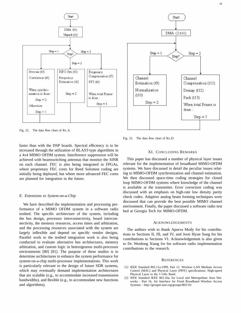
18
Fig. 22. The data flow chart of RxA.
faster than with the DSP boards. Spectral efficiency is to beincreased through the utilization of BLAST-type algorithms ina 4x4 MIMO OFDM system. Interference suppression will beachieved with beamswitching antennas that monitor the SINRon each channel. FEC is also being integrated in FPGAs,where proprietary FEC cores for Reed Solomon coding areinitially being deployed, but where more advanced FEC coresare planned for integration in the future.
E. Extensions to System-on-a-Chip
We have described the implementation and processing per-formance of a MIMO OFDM system in a software radiotestbed. The specific architecture of the system, includingthe bus design, processor interconnectivity, board intercon-nectivity, the memory resources, access times and arbitration,and the processing resources associated with the system arelargely inflexible and depend on specific vendor designs.Parallel work to the testbed integration work is also beingconducted to evaluate alternative bus architectures, memoryarbitration, and custom logic in heterogenous multi-processorenvironments [80] [81]. The purpose of these studies is todetermine architectures to enhance the system performance forsystem-on-a-chip multi-processor implementations. This workis particularly relevant to the design of future SDR systems,which may eventually demand implementation architecturesthat are scalable (e.g., to accommodate increased transmissionbandwidths), and flexible (e.g., to accommodate new functionsand algorithms).
Fig. 23. The data flow chart of RxD.
XI. CONCLUDING REMARKS
This paper has discussed a number of physical layer issuesrelevant for the implementation of broadband MIMO-OFDMsystems. We have discussed in detail the peculiar issues relat-ing to MIMO-OFDM synchronization and channel estimation.We then discussed space-time coding strategies for closedloop MIMO-OFDM systems where knowledge of the channelis available at the transmitter. Error correction coding wasdiscussed with an emphasis on high-rate low density paritycheck codes. Adaptive analog beam forming techniques werediscussed that can provide the best possible MIMO channelenvironment. Finally, the paper discussed a software radio testbed at Georgia Tech for MIMO-OFDM.
ACKNOWLEDGEMENTS
The authors wish to thank Apurva Mody for his contribu-tions to Sections II, III, and IV, and Joon Hyun Sung for hiscontributions to Sections VI. Acknowledgement is also givento Dr. Weidong Xiang for his software radio implementationcontributions to the research.
REFERENCES
[1] IEEE Standard 802.11a-1999, Part 11: Wireless LAN Medium AccessControl (MAC) and Physical Layer (PHY) specifications: High-speedPhysical Layer in the 5 GHz Band.
[2] IEEE Standard IEEE 802.16a, for Local and Metropolitan Area Net-works - Part 16, Air Interface for Fixed Broadband Wireless AccessSystems - http://grouper.ieee.org/groups/802/16/
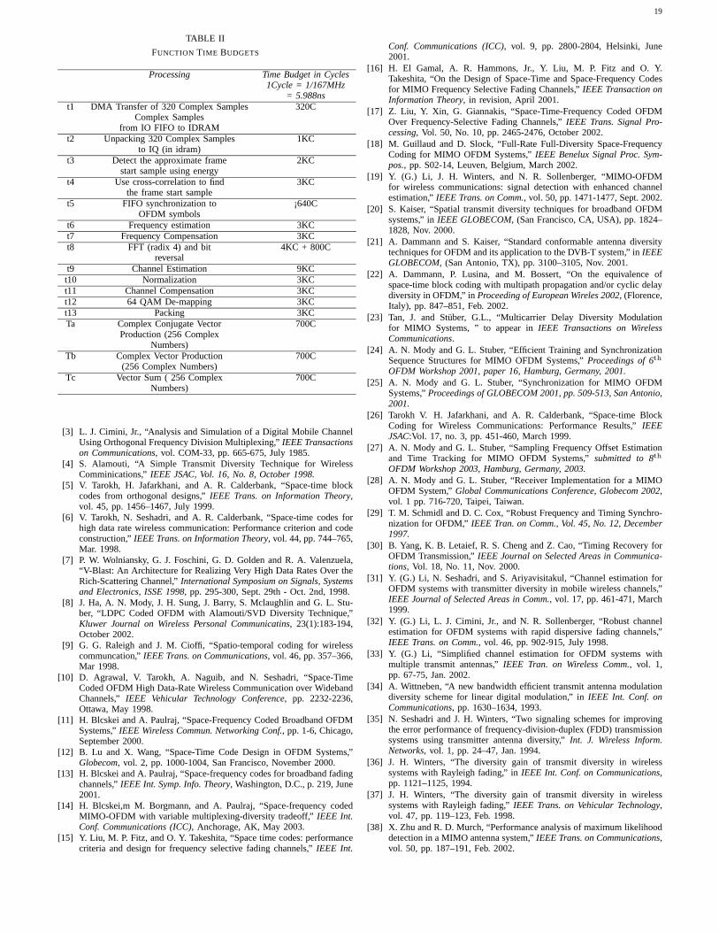
19
TABLE II
FUNCTION TIME BUDGETS
Processing Time Budget in Cycles1Cycle = 1/167MHz
= 5.988nst1 DMA Transfer of 320 Complex Samples 320C
Complex Samplesfrom IO FIFO to IDRAM
t2 Unpacking 320 Complex Samples 1KCto IQ (in idram)
t3 Detect the approximate frame 2KCstart sample using energy
t4 Use cross-correlation to find 3KCthe frame start sample
t5 FIFO synchronization to ¡640COFDM symbols
t6 Frequency estimation 3KCt7 Frequency Compensation 3KCt8 FFT (radix 4) and bit 4KC + 800C
reversalt9 Channel Estimation 9KCt10 Normalization 3KCt11 Channel Compensation 3KCt12 64 QAM De-mapping 3KCt13 Packing 3KCTa Complex Conjugate Vector 700C
Production (256 ComplexNumbers)
Tb Complex Vector Production 700C(256 Complex Numbers)
Tc Vector Sum ( 256 Complex 700CNumbers)
[3] L. J. Cimini, Jr., “Analysis and Simulation of a Digital Mobile ChannelUsing Orthogonal Frequency Division Multiplexing,”IEEE Transactionson Communications, vol. COM-33, pp. 665-675, July 1985.
[4] S. Alamouti, “A Simple Transmit Diversity Technique for WirelessComminications,”IEEE JSAC, Vol. 16, No. 8, October 1998.
[5] V. Tarokh, H. Jafarkhani, and A. R. Calderbank, “Space-time blockcodes from orthogonal designs,”IEEE Trans. on Information Theory,vol. 45, pp. 1456–1467, July 1999.
[6] V. Tarokh, N. Seshadri, and A. R. Calderbank, “Space-time codes forhigh data rate wireless communication: Performance criterion and codeconstruction,”IEEE Trans. on Information Theory, vol. 44, pp. 744–765,Mar. 1998.
[7] P. W. Wolniansky, G. J. Foschini, G. D. Golden and R. A. Valenzuela,“V-Blast: An Architecture for Realizing Very High Data Rates Over theRich-Scattering Channel,”International Symposium on Signals, Systemsand Electronics, ISSE 1998, pp. 295-300, Sept. 29th - Oct. 2nd, 1998.
[8] J. Ha, A. N. Mody, J. H. Sung, J. Barry, S. Mclaughlin and G. L. Stu-ber, “LDPC Coded OFDM with Alamouti/SVD Diversity Technique,”Kluwer Journal on Wireless Personal Communicatins, 23(1):183-194,October 2002.
[9] G. G. Raleigh and J. M. Cioffi, “Spatio-temporal coding for wirelesscommuncation,”IEEE Trans. on Communications, vol. 46, pp. 357–366,Mar 1998.
[10] D. Agrawal, V. Tarokh, A. Naguib, and N. Seshadri, “Space-TimeCoded OFDM High Data-Rate Wireless Communication over WidebandChannels,” IEEE Vehicular Technology Conference, pp. 2232-2236,Ottawa, May 1998.
[11] H. Blcskei and A. Paulraj, “Space-Frequency Coded Broadband OFDMSystems,”IEEE Wireless Commun. Networking Conf., pp. 1-6, Chicago,September 2000.
[12] B. Lu and X. Wang, “Space-Time Code Design in OFDM Systems,”Globecom, vol. 2, pp. 1000-1004, San Francisco, November 2000.
[13] H. Blcskei and A. Paulraj, “Space-frequency codes for broadband fadingchannels,”IEEE Int. Symp. Info. Theory, Washington, D.C., p. 219, June2001.
[14] H. Blcskei,m M. Borgmann, and A. Paulraj, “Space-frequency codedMIMO-OFDM with variable multiplexing-diversity tradeoff,”IEEE Int.Conf. Communications (ICC), Anchorage, AK, May 2003.
[15] Y. Liu, M. P. Fitz, and O. Y. Takeshita, “Space time codes: performancecriteria and design for frequency selective fading channels,”IEEE Int.
Conf. Communications (ICC), vol. 9, pp. 2800-2804, Helsinki, June2001.
[16] H. El Gamal, A. R. Hammons, Jr., Y. Liu, M. P. Fitz and O. Y.Takeshita, “On the Design of Space-Time and Space-Frequency Codesfor MIMO Frequency Selective Fading Channels,”IEEE Transaction onInformation Theory, in revision, April 2001.
[17] Z. Liu, Y. Xin, G. Giannakis, “Space-Time-Frequency Coded OFDMOver Frequency-Selective Fading Channels,”IEEE Trans. Signal Pro-cessing, Vol. 50, No. 10, pp. 2465-2476, October 2002.
[18] M. Guillaud and D. Slock, “Full-Rate Full-Diversity Space-FrequencyCoding for MIMO OFDM Systems,”IEEE Benelux Signal Proc. Sym-pos., pp. S02-14, Leuven, Belgium, March 2002.
[19] Y. (G.) Li, J. H. Winters, and N. R. Sollenberger, “MIMO-OFDMfor wireless communications: signal detection with enhanced channelestimation,”IEEE Trans. on Comm., vol. 50, pp. 1471-1477, Sept. 2002.
[20] S. Kaiser, “Spatial transmit diversity techniques for broadband OFDMsystems,” inIEEE GLOBECOM, (San Francisco, CA, USA), pp. 1824–1828, Nov. 2000.
[21] A. Dammann and S. Kaiser, “Standard conformable antenna diversitytechniques for OFDM and its application to the DVB-T system,” inIEEEGLOBECOM, (San Antonio, TX), pp. 3100–3105, Nov. 2001.
[22] A. Dammann, P. Lusina, and M. Bossert, “On the equivalence ofspace-time block coding with multipath propagation and/or cyclic delaydiversity in OFDM,” inProceeding of European Wireles 2002, (Florence,Italy), pp. 847–851, Feb. 2002.
[23] Tan, J. and Stuber, G.L., “Multicarrier Delay Diversity Modulationfor MIMO Systems, ” to appear inIEEE Transactions on WirelessCommunications.
[24] A. N. Mody and G. L. Stuber, “Efficient Training and SynchronizationSequence Structures for MIMO OFDM Systems,”Proceedings of 6th
OFDM Workshop 2001, paper 16, Hamburg, Germany, 2001.[25] A. N. Mody and G. L. Stuber, “Synchronization for MIMO OFDM
Systems,”Proceedings of GLOBECOM 2001, pp. 509-513, San Antonio,2001.
[26] Tarokh V. H. Jafarkhani, and A. R. Calderbank, “Space-time BlockCoding for Wireless Communications: Performance Results,”IEEEJSAC:Vol. 17, no. 3, pp. 451-460, March 1999.
[27] A. N. Mody and G. L. Stuber, “Sampling Frequency Offset Estimationand Time Tracking for MIMO OFDM Systems,”submitted to 8th
OFDM Workshop 2003, Hamburg, Germany, 2003.[28] A. N. Mody and G. L. Stuber, “Receiver Implementation for a MIMO
OFDM System,”Global Communications Conference, Globecom 2002,vol. 1 pp. 716-720, Taipei, Taiwan.
[29] T. M. Schmidl and D. C. Cox, “Robust Frequency and Timing Synchro-nization for OFDM,” IEEE Tran. on Comm., Vol. 45, No. 12, December1997.
[30] B. Yang, K. B. Letaief, R. S. Cheng and Z. Cao, “Timing Recovery forOFDM Transmission,”IEEE Journal on Selected Areas in Communica-tions, Vol. 18, No. 11, Nov. 2000.
[31] Y. (G.) Li, N. Seshadri, and S. Ariyavisitakul, “Channel estimation forOFDM systems with transmitter diversity in mobile wireless channels,”IEEE Journal of Selected Areas in Comm., vol. 17, pp. 461-471, March1999.
[32] Y. (G.) Li, L. J. Cimini, Jr., and N. R. Sollenberger, “Robust channelestimation for OFDM systems with rapid dispersive fading channels,”IEEE Trans. on Comm., vol. 46, pp. 902-915, July 1998.
[33] Y. (G.) Li, “Simplified channel estimation for OFDM systems withmultiple transmit antennas,”IEEE Tran. on Wireless Comm., vol. 1,pp. 67-75, Jan. 2002.
[34] A. Wittneben, “A new bandwidth efficient transmit antenna modulationdiversity scheme for linear digital modulation,” inIEEE Int. Conf. onCommunications, pp. 1630–1634, 1993.
[35] N. Seshadri and J. H. Winters, “Two signaling schemes for improvingthe error performance of frequency-division-duplex (FDD) transmissionsystems using transmitter antenna diversity,”Int. J. Wireless Inform.Networks, vol. 1, pp. 24–47, Jan. 1994.
[36] J. H. Winters, “The diversity gain of transmit diversity in wirelesssystems with Rayleigh fading,” inIEEE Int. Conf. on Communications,pp. 1121–1125, 1994.
[37] J. H. Winters, “The diversity gain of transmit diversity in wirelesssystems with Rayleigh fading,”IEEE Trans. on Vehicular Technology,vol. 47, pp. 119–123, Feb. 1998.
[38] X. Zhu and R. D. Murch, “Performance analysis of maximum likelihooddetection in a MIMO antenna system,”IEEE Trans. on Communications,vol. 50, pp. 187–191, Feb. 2002.
20
[39] A. Duel-Hallen, “Equalizers for multiple input/multiple output channelsand PAM systems with cyclostationary input sequences,”IEEE J. onSelected Areas in Communications, vol. 10, pp. 630–639, Apr. 1992.
[40] J. H. Sung and J. R. Barry, “Bit-Allocation Strategies for MIMO FadingChannels with Channel Knowledge at the Transmitter,”VTC Spring,Jeju, Korea, April 2003.
[41] J. H. Sung and J. R. Barry, “Bit-Allocation Strategies for Closed-LoopMIMO OFDM,” to appear, Vehicular Technology Conference (VTC03),Orlando, October 4-9, 2003.
[42] Gallager, R. G.Low-Density Parity-Check Codes, Cambridge, MA: MITPress, 1963.
[43] MacKay, D. J. C. “Good Error-Correcting Codes Based on Sparse VeryMatrices,” IEEE Trans. on Information Theory: 45(2): 399-431, March1999.
[44] J. Ha, J. Kim and S.W. McLaughlin, “Rate compatible puncturing ofLDPCs,” to appearIEEE Transactions on Information Theory.
[45] C. Jones, T. Tian, A. Matache, R. Wesel, J. Villasenor, “Robustness ofLDPCs on periodic fading channels”Globecom 2002, Taipei, Taiwan.
[46] L. Goulet and H. Leib, “Serially Concatenated SpaceTime Codes WithIterative Decoding and Performance Limits of Block-Fading Channels,”IEEE Journal on Selected Areas in Communications, vol. 21, no. 5, pp.765-773, June 2003.
[47] A. Stefanov and T. Duman, “Performance Bounds for Turbo-CodedMultiple Antenna Systems”IEEE Journal on Selected Areas in Com-munications, vol. 21, no. 3, pp. 374-381, April 2003.
[48] B. Hassibi and B. Hochwald, “High-Rate Codes That Are Linear inSpace and Time,”IEEE Transactions on Information Theory, vol. 48,no. 7, pp. 1804-1825, July 2002.
[49] W. Su, Z. Safar, M. Olfat, R. Liu, “Obtaining Full-Diversity Space-Frequency Codes From Space-Time Codes via Mapping,”IEEE Trans.Signal Processing, Vol. 51, No. 11, pp. 2905-2916, November 2003.
[50] K. Lee and D. Williams, “A Space-Frequency Transmitter DiversityTechnique for OFDM Systems ,”Globecom, vol. 3, pp. 1473-1477, 2000.
[51] R. Blum, Y. (G.) Li, J. Winters, and Q. Yam, “Improved Space-TimeCoding for MIMO-OFDM Wireless Communications ,”IEEE Trans.Commun., vol. 49, pp. 1873-1878, Nov. 2001.
[52] Y. Gong and K. Letaief, “An Efficient Space-Frequency Coded Wide-band OFDM System for Wireless Communications,”ICC, vol. 1, pp.475-479, 2002.
[53] B. Lu, X. Wang, and K. Narayanan, “LDPC-based space-time codedOFDM systems over correlated fading channels: Performance analysisand receiver design,”IEEE Transactions on Communications, vol. 50,no. 1, pp. 74-88, January 2002.
[54] Y. Liu and M. Fitz, “Space-time turbo codes,”Proceedings of 37thAnnual Allerton Conference, Monticello, IL, Sept 1999.
[55] R.W. Heath, S. Sandhu, and A. Paulraj, “Antenna selection for spatialmultiplexing systems with linear receivers”IEEE Communications Let-ters, vol. 5, pp. 142-144, April 2001.
[56] D. Gore and A. Paulraj, “Space-time block coding with optimal antennaselection,” IEEE International Conference on Acoustics, Speech, andSignal Processing, vol. 4, pp. 2441-2444, 2001.
[57] R.S. Blum and J.H. Winters, “On optimum MIMO with antenna selec-tion,” IEEE International Conference on Communications, vol. 1, pp.386-390, 2002.
[58] R.S. Blum and J.H. Winters, “On optimum MIMO with antenna selec-tion,” IEEE Communications Letters, vol. 6, pp. 322-324, 2002.
[59] K. U-yen, J.S. Kenney, T. Assavapokee, “An optimization technique forlow-loss nXm microwave switch matrices,”Proc. 2003 IEEE Radio andWireless Conference (RAWCON), Boston MA, August 11-13, 2003.
[60] H. Shi, M. Katayama, T. Yamazato, H. Okada and A. Ogawa, “Anadaptive antenna selection scheme for transmit diversity in OFDMsystems,”IEEE Vehicular Technology Conference, vol. 4, pp. 2168-2172,2001.
[61] H. Asplund, A.F. Molisch, M. Steinbauer and N.B. Mehta, “Clusteringof scatterers in mobile radio channels - evaluation and modeling in theCOST259 directional channel model,”IEEE International Conferenceon Communications, vol. 2, pp. 901-905, 2002.
[62] C.-C. Chong, C.-M. Tan, D.I. Laurenson, S. McLaughlin, M.A. Beachand A.R. Nix, “A new statistical wideband spatio-temporal channelmodel for 5-GHz band WLAN systems,”IEEE Journal on SelectedAreas in Communications, Vol. 21, No. 2, February 2003.
[63] J. H. Winters and M. J. Gans, “The range increase of adaptive versusphased arrays in mobile radio systems,”IEEE Trans. Veh. Technol., vol.48, pp. 353362, Mar. 1999.
[64] R.J. Mailloux, “Phase Array Antenna Handbook”,Artech House Inc.,1994.
[65] F. Caldwell, J.S. Kenney, M.A.Ingram, “Design and Implementation of aSwitched-Beam Smart Antenna for an 802.11b Wireless Access Point,”Proc. 2002 IEEE Radio and Wireless Conference (RAWCON), BostonMA, August 11-14, 2002.
[66] K.-H.Li, M.A. Ingram, E.O. Rausch, “Multibeam antennas for indoorwireless communications,”IEEE Transactions on Communications, Vol.50, No. 2, pp. 192-194, February 2002.
[67] K.-H.Li and M.A. Ingram, “Space-time block-coded OFDM systemswith RF beamformers for high-speed indoor wireless communications,”IEEE Transactions on Communications, Vol. 50, No. 12, pp. 1899-1901,December 2002.
[68] L. Dong and M.A. Ingram, “Beam selection algorithm based on PTRmetric and its synchronization performance,”Proc. 2003 IEEE Radioand Wireless Conference (RAWCON), Boston MA, August 11-13, 2003.
[69] J.-S. Jiang and M.A. Ingram, “Comparison of beam selection andantenna selection techniques in indoor MIMO systems at 5.8 GHz,”Proc. 2003 IEEE Radio and Wireless Conference (RAWCON), BostonMA, August 11-13, 2003.
[70] M.F. Demirkol and M.A. Ingram, “Stream Control in Networks withInterfering MIMO Links,” Proc. IEEE Wireless Communications andNetworking Conference (WCNC), New Orleans, LA, 16-20 March 2003.
[71] http://www.sdrforum.org[72] J. Mitola,“The Software Radio Architecture,”IEEE Communications
Magazine, pp. 26-38, May 1995[73] E. Sereni et al, “A Software Radio OFDM Transceiver for WLAN
applications” http://www.di.uoa.gr/speech/dsp/X/PERUGI.PDF[74] S. Gifford, J. Kleider, and S. Chuprin, “Broadband OFDM Using 16-bit
Precision on a SDR Platform,”Proc. MILCOM 2001, pp. 180-184, Oct2001.
[75] Kwang-Cheng Chen and Shan-Tsung Wu, “A Programmable Architec-ture for OFDM-CDMA,” IEEE Communications Magazine, Vol. 37 No.11, pp. 76-82, November 1999.
[76] J.D. Bakker and F.C. Schoute, “LART: Design and implementation of anexperimental wireless platform,”Proc. IEEE VTC 2000, pp. 1460-1466.
[77] M. Fahim Tariq et al, “Development of an OFDM based Hgh-SpeedWireless LAN Platform using the TI C6X DSP,”Proc. IEEE Interna-tional Conference on Communications pp. 522-526, April/May 2002.
[78] K. Witrisal et al, “Air-interface Emulation for Wireless BroadbandCommunications Applied to OFDM,”Proc. Personal, Indoor and MobileRadio Communications, pp. 1251-1255, Sept. 2000
[79] W. Xiang, T. Pratt, N. Jones, X. Wang, L. Dong, and T.l Zhang,“A Software Radio MIMO-OFDM Prototype for Broadband WirelessAccess, PartI: System Architecture,”in preparation.
[80] Kyeong Keol Ryu, Eung Shin, V.J. Mooney III, “A comparison offive different multiprocessor SoC bus architectures,”Proc. EuromicroSymposium on Digital Systems Design, pp-. 202-9, Sept. 2001
[81] B.E Saglam and V.J. Mooney III., “System-on-a-chip processor syn-chronization support in hardware,”Proc. Design, Automation and Testin Europe, pp. 633-9, March 2001.
21
Gordon L. Stber received the B.A.Sc. and Ph.D.degrees in Electrical Engineering from the Univer-sity of Waterloo, Ontario, Canada, in 1982 and1986 respectively. Since 1986, he has been withthe School of Electrical and Computer Engineering,Georgia Institute of Technology, where he is cur-rently the Joseph M. Pettit Professor in Communi-cations.
Dr. Stber’s research interests are in wireless com-munications and communication signal processing.He is author of the textbook Principles of Mobile
Communication, Kluwer Academic Publishers, 1996, 2/e 2001. He wasco-recipient of the Jack Neubauer Memorial Award in 1997 recognizingthe best systems paper published in the IEEE Transactions on VehicularTechnology. He became an IEEE Fellow in 1999 for contributions to mobileradio and spread spectrum communications. He received the IEEE VehicularTechnology Society James R. Evans Avant Garde Award in 2003 recognizinghis contributions to theoretical research in wireless communications.
Dr. Stber served as Technical Program Chair for the 1996 IEEE VehicularTechnology Conference (VTC’96), Technical Program Chair for the 1998IEEE International Conference on Communications (ICC’98), General Chairof the Fifth IEEE Workshop on Multimedia, Multiaccess and Teletraffic forWireless Communications (MMT’2000), General Chair of the 2002 IEEECommunication Theory Workshop, and and General Chair of the FifthInternational Symposium on Wireless Personal Multimedia Communications(WPMC’2002). He is a past Editor for Spread Spectrum with the IEEETransactions on Communications (1993-1998), and a past member of the IEEECommunications Society Awards Committee (1999-2002). He is currentlyan elected member of the IEEE Vehicular Technology Society Board ofGovernors (2001-2003, 2004-2006).
John R. Barry received the B.S. degree in electricalengineering from the State University of New Yorkat Buffalo in 1986 and the M.S. and Ph.D. degreesin electrical engineering from the University ofCalifornia at Berkeley in 1987 and 1992, respec-tively. Since 1992 he has been with the GeorgiaInstitute of Technology, Atlanta, where he is anAssociate Professor with the School of Electricaland Computer Engineering. His research interestsinclude wireless communications, equalization, andmultiuser communications. He is a coauthor with E.
A. Lee and D. G. Messerschmitt ofDigital Communications, Third Edition,Kluwer, 2004, and the author ofWireless Infrared Communications, Kluwer,1994.
Steve W. McLaughlin Steven W. McLaughlin re-ceived the B.S. degree from Northwestern Universityin 1985, the M.S.E. degree from Princeton Uni-versity in 1986, and the Ph.D. degree from theUniversity of Michigan in 1992. From 1992-1996he was on the Electrical Engineering faculty at theRochester Institute of Technology. He joined theSchool of ECE at Georgia Tech in September 1996.He is also a Principal Scientist at Calimetrics, Inc.His research interests are in the area of communica-tions and information theory. Specific interests are
in turbo and constrained codes for magnetic and optical recording, FEC andequalization for optical networks, theory of error control coding, and sourcecoding (quantization and compression).
He received the Presidential Early Career Award for Scientists and Engi-neers (PECASE) where he was cited by President Clinton ”for leadershipin the development of high-capacity, nonbinary optical recording formats.”He also received the National Science Foundation CAREER award for thiswork. He is currently Second Vice President of the IEEE Information TheorySociety. He served as the Publications Editor for the IEEE Transactionson Information Theory from 1995-1999. He co-edited (with Sergio Verdu)Information Theory: 50 years of Discovery (IEEE Press, 1999). He is a seniormember of the IEEE. He has also served on the IEEE Publications ActivitiesBoard (1998-2001) and is a former Secretary of the IEEE Atlanta Section(2000).
Ye (Geoffrey) Li received his B.S.E. and M.S.E.degrees in 1983 and 1986, respectively, from the De-partment of Wireless Engineering, Nanjing Instituteof Technology, Nanjing, China, and his Ph.D. degreein 1994 from the Department of Electrical Engineer-ing, Auburn University, Alabama. After spendingseveral years at AT&T Labs - Research, he joinedGeorgia Tech as an Associate Professor in 2000. Hisgeneral research interests include statistical signalprocessing and wireless communications. In theseareas, he has contributed over 100 papers published
in referred journals and presented in various international conferences. He alsohas over 10 USA patents granted or pending. He once served as a guest editorfor two special issues on Signal Processing for Wireless Communicationsfor the IEEE J-SAC. He is currently serving as an editor for WirelessCommunication Theory for the IEEE Transactions on Communications and aneditorial board member of EURASIP Journal on Applied Signal Processing.He organized and chaired many international conferences, including Vice-Chair of IEEE 2003 International Conference on Communications.
Mary Ann Ingram received the B.E.E. and Ph.D.degrees from the Georgia Institute of Technology(Georgia Tech) in 1983 and 1989, respectively. From1983 to 1986, she was a Research Engineer withthe Georgia Tech Research Institute in Atlanta, per-forming studies on radar electronic countermeasure(ECM) systems. In 1986, she became a graduateresearch assistant with the School of Electrical andComputer Engineering at Georgia Tech, where in1989, she became a Faculty Member and is currentlyan Associate Professor. Her early research areas
were optical communications and radar systems. Since 1997, her researchinterest has been the application of multiple antenna systems to wirelesscommunications. In particular, she and her students have investigated theuse of RF beamformers and RF switches in MIMO and adaptive array ar-chitectures, wideband MIMO channel measurement and stochastic modeling,multi-antenna architectures for semi-passive RF tags and their interrogators,and cross-layer algorithm development for networks with interfering MIMOlinks. Many of these projects involve the design and construction of hardwareprototypes.
PLACEPHOTOHERE
Thomas Pratt received his B.S from the Universityof Notre Dame, and his M.S. and Ph.D. degreesin Electrical Engineering from the Georgia Instituteof Technology. Dr. Pratt heads the software radiolaboratory at Georgia Tech, where research hasfocused principally on MIMO OFDM, space-timeadaptive processing, WLAN coexistence and inter-ference suppression, GSM receivers, and channelmodeling for mobile communications. He is a seniorresearch engineer at the Georgia Tech ResearchInstitute.


![Hard Decision-Based PWM for MIMO-OFDM Radar · 2. MIMO-OFDM Radar Signal Model-Based PWM 2.1. MIMO-OFDM Radar Systems Structure In [1], OFDM technique has the advantage of combating](https://img.pdfslide.net/doc/110x75/5e6a685a5002aa073940e3bf/hard-decision-based-pwm-for-mimo-ofdm-radar-2-mimo-ofdm-radar-signal-model-based.jpg)