Embed Size (px)
Citation preview
1
Broadband mm-Wave Microstrip Array Antennawith Improved Radiation Characteristics for
Different 5G ApplicationsMohsen Khalily, Member, IEEE, Rahim Tafazolli, Senior Member, IEEE, Pei Xiao, Senior Member, IEEE, and
Ahmed A. Kishk, Fellow, IEEE
Abstract—A Ka-band inset-fed microstrip patches linear an-tenna array is presented for the fifth generation (5G) applicationsin different countries. The bandwidth is enhanced by stackingparasitic patches on top of each inset-fed patch. The arrayemploys 16 elements in an H-plane new configuration. Theradiating patches and their feed lines are arranged in analternating out-of-phase 180-degree rotating sequence to decreasethe mutual coupling and improve the radiation pattern symmetry.A (24.4%) measured bandwidth (24.35 to 31.13 GHz)is achievedwith -15 dB reflection coefficients and 20 dB mutual couplingbetween the elements. With uniform amplitude distribution, amaximum broadside gain of 19.88 dBi is achieved. Scanning themain beam to 49.5 from the broadside achieved 18.7 dBi gainwith -12.1 dB sidelobe level (SLL). These characteristics are ingood agreement with the simulations, rendering the antenna tobe a good candidate for 5G applications.
Index Terms—26 GHz, 28 GHz, millimeter wave (mm-Wave),fifth generation (5G), mobile communication, array antenna,parasitic antenna.
I. INTRODUCTION
DUE to the shortage of frequency spectrum below 6 GHzbands and the need for higher data rate, higher frequen-
cies, e.g., millimeter-wave (mm-Wave) frequency bands, havebeen suggested as candidates for future fifth generation (5G)smart-phone applications, as the considerably more substantialbandwidth could be exploited to increase the capacity and en-able users to experience several-gigabits-per-second data rates[1]–[3]. However, one critical problem for mm-Wave wirelessis the increased link loss due to the reduced wavelength andatmospheric conditions [4], [5].
Commonly referred to as beamforming, a high gain narrowbeam radiation pattern synthesized by an array consisting ofmultiple antenna elements with optimized spacing is a solutionto combat the increased path loss at mm-Wave frequencies.Also at mm-Wave frequencies, communication is mostly lineof sight (LoS), communication links can thus be disrupted ifthe line of sight is not maintained. This can be solved byvarying the phase shift associated with each antenna element,thereby steering the overall radiation pattern of the array [1]–[5].
This work was supported in part by the 5GIC, University of Surrey, U.K.Mohsen Khalily, R. Tafazolli, and P. Xiao are with the Institute for Commu-
nication Systems, 5GIC, University of Surrey, Guildford, GU2 7XH, U.K. (e-mail: [email protected]; [email protected]; [email protected]).
Ahmed A Kishk is with the Department of Electrical and ComputerEngineering, Concordia University, Montreal, QC H3G 2W1, Canada (e-mail:[email protected]).
Although planar phased arrays have gone through intensiveinvestigations, to date, limited research has been conducted onarray antennas or phased arrays for mobile units [5], [6]. In [7],the authors present the motivation for new mm-Wave cellularsystems, methodology, and hardware for measurements andoffer a variety of measurement results showing that 28 and38 GHz frequencies can be used when employing steerabledirectional antennas at base stations and mobile devices. Anew dense dielectric patch array antenna using electromagneticband gap (EBG) ground structure and dielectric superstratewas recently proposed in [8] with an improved radiationcharacteristic, a high gain about 16.3 dBi and bandwidthfrom 27 GHz to beyond 32 GHz. In [5], a 2-GHz bandwidtharound 28 GHz, an 11 dBi gain and wide space coveragewere achieved by using a thick multilayer coplanar waveguide-based array antenna. A new phased array antenna based on anopen slot-PIFA integrated with the mobile phone chassis wasdesigned in [3] with a bandwidth of 6 GHz around 29 GHzand a gain of about 13 dBi. In [9], notch antennas based onmicrostrip feeding and aperture coupled slot antennas wereemployed to design 1×4 arrays. Even though the antennawas compact, the bandwidth achieved was narrow. Finally,we recently proposed a new 28 GHz series-fed phased arrayantenna in [10] with a reduced number of the phase controllersand 15.6 dBi gain. In this work, a measured bandwidth ofabout 2 GHz around 28 GHz and a low beam scanning rangeof about 24 were obtained.
To overcome the above-stated problems, a high gain arrayantenna system with broadband frequency performance, propermatching, stable radiation characteristics and high capabilityfor beam scanning along with suitable sidelobe level (SLL)and the sharp radiating beam is achieved. Furthermore, theproposed antenna covers the 5G spectrum in different coun-tries, such as 26 GHz band in Europe [11] and the 28 GHzband in the US [12].
In this paper, these goals are considered in the designof a new array antenna prototype from 25 to 30 GHz for5G spectrum supported in different countries and regions,especially Europe, USA and Asia. In the next section, thedesign of a single inset-fed patch antenna with an equal-sizeparasitic patch and its radiation and impedance characteristicsare presented. In the following, a 16-element array antennawith a new configuration is proposed and designed to obtainthe highest possible gain and bandwidth as well as goodradiation performance. The two innovations of this design
2
include 1- not-aligned antenna patches relative to each other tocreate symmetry in the final radiation fields, and 2- applyingparasitic patches to the array antenna to increase the gainand bandwidth. Finally, the measurement results compared tothe simulations as well as other works and conclusion arepresented, respectively.
II. DESIGN OF A SINGLE PARASITIC-BASED INSET-FEDPATCH ANTENNA
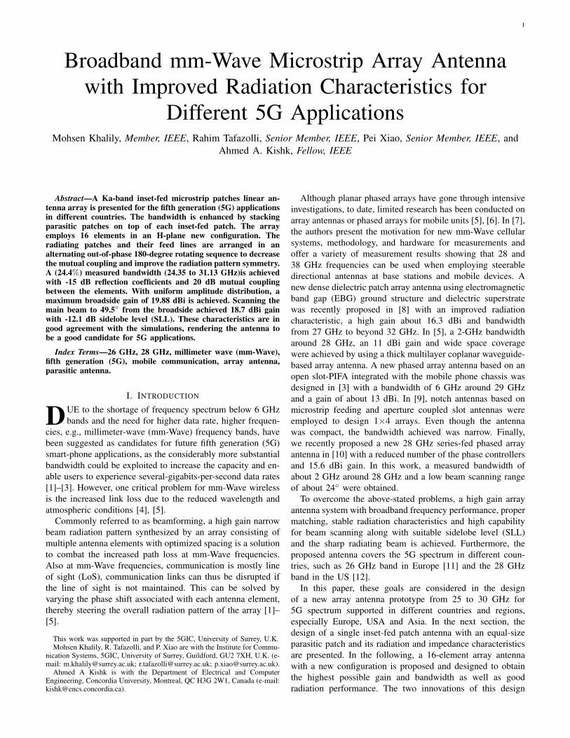
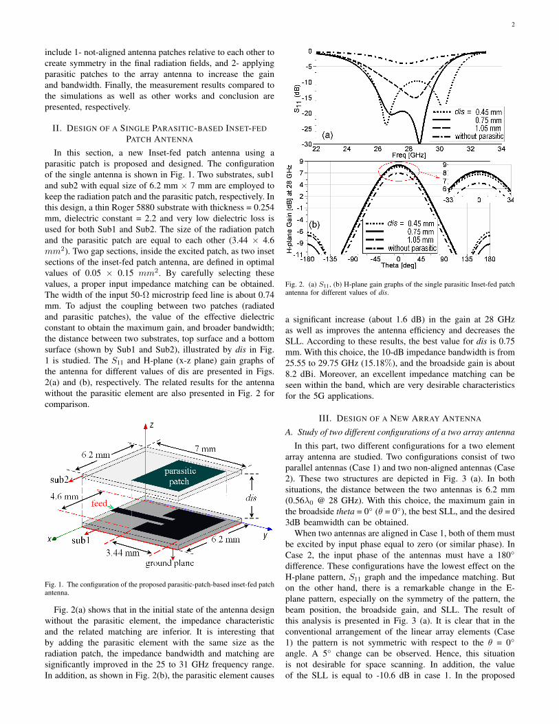
In this section, a new Inset-fed patch antenna using aparasitic patch is proposed and designed. The configurationof the single antenna is shown in Fig. 1. Two substrates, sub1and sub2 with equal size of 6.2 mm × 7 mm are employed tokeep the radiation patch and the parasitic patch, respectively. Inthis design, a thin Roger 5880 substrate with thickness = 0.254mm, dielectric constant = 2.2 and very low dielectric loss isused for both Sub1 and Sub2. The size of the radiation patchand the parasitic patch are equal to each other (3.44 × 4.6mm2). Two gap sections, inside the excited patch, as two insetsections of the inset-fed patch antenna, are defined in optimalvalues of 0.05 × 0.15 mm2. By carefully selecting thesevalues, a proper input impedance matching can be obtained.The width of the input 50-Ω microstrip feed line is about 0.74mm. To adjust the coupling between two patches (radiatedand parasitic patches), the value of the effective dielectricconstant to obtain the maximum gain, and broader bandwidth;the distance between two substrates, top surface and a bottomsurface (shown by Sub1 and Sub2), illustrated by dis in Fig.1 is studied. The S11 and H-plane (x-z plane) gain graphs ofthe antenna for different values of dis are presented in Figs.2(a) and (b), respectively. The related results for the antennawithout the parasitic element are also presented in Fig. 2 forcomparison.
Fig. 1. The configuration of the proposed parasitic-patch-based inset-fed patchantenna.
Fig. 2(a) shows that in the initial state of the antenna designwithout the parasitic element, the impedance characteristicand the related matching are inferior. It is interesting thatby adding the parasitic element with the same size as theradiation patch, the impedance bandwidth and matching aresignificantly improved in the 25 to 31 GHz frequency range.In addition, as shown in Fig. 2(b), the parasitic element causes
Fig. 2. (a) S11, (b) H-plane gain graphs of the single parasitic Inset-fed patchantenna for different values of dis.
a significant increase (about 1.6 dB) in the gain at 28 GHzas well as improves the antenna efficiency and decreases theSLL. According to these results, the best value for dis is 0.75mm. With this choice, the 10-dB impedance bandwidth is from25.55 to 29.75 GHz (15.18%), and the broadside gain is about8.2 dBi. Moreover, an excellent impedance matching can beseen within the band, which are very desirable characteristicsfor the 5G applications.
III. DESIGN OF A NEW ARRAY ANTENNA
A. Study of two different configurations of a two array antenna
In this part, two different configurations for a two elementarray antenna are studied. Two configurations consist of twoparallel antennas (Case 1) and two non-aligned antennas (Case2). These two structures are depicted in Fig. 3 (a). In bothsituations, the distance between the two antennas is 6.2 mm(0.56λ0 @ 28 GHz). With this choice, the maximum gain inthe broadside theta = 0 (θ = 0), the best SLL, and the desired3dB beamwidth can be obtained.
When two antennas are aligned in Case 1, both of them mustbe excited by input phase equal to zero (or similar phase). InCase 2, the input phase of the antennas must have a 180
difference. These configurations have the lowest effect on theH-plane pattern, S11 graph and the impedance matching. Buton the other hand, there is a remarkable change in the E-plane pattern, especially on the symmetry of the pattern, thebeam position, the broadside gain, and SLL. The result ofthis analysis is presented in Fig. 3 (a). It is clear that in theconventional arrangement of the linear array elements (Case1) the pattern is not symmetric with respect to the θ = 0
angle. A 5 change can be observed. Hence, this situationis not desirable for space scanning. In addition, the valueof the SLL is equal to -10.6 dB in case 1. In the proposed

3
(a) (b)
Fig. 3. (a) Two different configurations (aligned and non-aligned) for a 2×1 array antenna, and their E-plane (y-z plane) gain graphs at 28 GHz, (b) Theconfiguration of the proposed 16-element parasitic-patch-based Inset-fed patch array antenna.
case (Case 2), the pattern is symmetric, as you can see fromFig. 3 (a). Moreover, the values of the broadside gain andSLL have been improved by about 0.34 dB and 7.5 dB,respectively. As a result, designing a large array antenna usingthe proposed configuration (Case 2) can produce desirableradiation performance for practical deployment.
B. Design of a new 16-element array antenna
In this part, the main goal is to design an array antennausing the proposed two array configuration and as large as atypical mobile phone. Hence, the maximum array length canbe around 100 mm. In this study, two different situations forthe main beam position are considered in the H-plane pattern:1) the beam position at θ= 0 and 2) the scanning direction at θ= ±45. It should be noted that our reference to determine andaccept the maximum possible scanning is SLL of -10 dB. Thestructure of the proposed 16-element linear array antenna isshown in Fig. 3(b). The total size of the design is 17.45 × 99.2mm2. In this design, 16 parasitic elements are employed at thetop surface of Sub2 with a size of 3.44 × 4.6 mm2 equal to theexcited inset-fed patches. The other properties of the designare defined in Fig. 3(b). In order to simulate the antenna array,16 feed ports (P1 to P16) are excited by input signals withequal amplitudes, but different phases to scan the main beamin the x-z plane. It is noted that the distance between the arrayelements (for example: between P1 and P2) is about 6.2 mm(0.56λ0 @ 28 GHz). Moreover, we know that to scan the mainbeam from θ = 0 (z-axis) to θ = 90 (x-axis) and place it ata specific angle θ0 (0 < θ < 90), a definite phase difference(= dphi), equal to βdsin(θ0) is needed between each pair ofarray elements, consecutively. Here, β is equal to 2π / λ0 andd = 0.56λ0. Hence, the parameter dphi is equal to 1.12π ×sin(θ0). On the other hand, by considering the excitation phasemechanism of the antennas, proposed in Fig. 3(a) (Case2) andthe crucial phase difference (= dphi) required between themto direct the main beam, the input excitation phase of eachfeed port (]p.i,i = 1, 2, . . . , 16) is defined by the followingequation:
]p.n = (n− 1) × dphi i = 1, 3, . . . , 15
]p.n = 180 + (n− 1) × dphi i = 2, 4, . . . , 16(1)
In this study, by considering the reference SLL = -10 dBand our parametric simulations, the parameter θ0 is selectedto be about 50. Therefore, the value of dphi will be equalto 154.5. As mentioned above, two different situations forthe main beam directions, θ0 = 0 and ±50 are selected tobe studied. All simulations are performed by finite-element-method (FEM)-based Ansoft HFSS software. For the firstposition of the main beam (θ = 0, dphi = 0), the simulatedS parameters, H-plane (x-z plane) and E-plane (y-z plane)pattern gains of the proposed array antenna at 28 GHz areshown in Fig. 4, respectively. From Fig. 4(a), it is seen thatthe 10-dB bandwidth is from 25.3 to 30 GHz (17%). Theisolation between nearest two ports (P1 and P2) is more than19 dB within the band mentioned above. As desired, Fig. 4(b)shows the main beam is located at θ0 = 0. In addition, thedifference between co- and cross-polar is more than 50 dB inthe broadside and the front to back ratio is better than 25 dB. Awide beam in broadside for E-plane pattern can be seen in Fig.4(c). Here, the difference between co- and cross-polar is morethan 50 dB. Fig. 5 presents the graphs of the same parametersmentioned above, for the main beam at (θ0 = ±50, dphi =154.5) of the proposed array at 28 GHz. It is clearly seenfrom Fig. 5(a) that the impedance bandwidths and isolationare similar to the previous results of the broadside direction.The main beam scanned to -49 is shown in Fig. 5(b). Here,the difference between co- and cross-polar is better than 53 dBaround θ = -49. Again, a wide beam and a high differencebetween co- and cross-polar (more than 23 dB) in E-planepattern are seen in Fig. 5(c).
In the final step of the simulation, for further investigationof array antenna performance within the bandwidth, the H-plane pattern of the array at 26 GHz is also presented in Fig.6. As can be seen in the figure, both cases with different beamdirections are shown for comparison. The radiation propertiesare summarized in Table I. It is interesting to note that themain beam of the scanned case is located at -54 with highgain and SLL. The -54 scanned has a scanning loss of 0.78dB. The 3dB beamwidths are less than 9 in both cases.These feature characteristics for a 5G spectrum are supportedby different countries. The other important parameters of theradiation patterns of the proposed array antenna in the twocases are summarized in Table I for 26 and 28 GHz. As

4
Fig. 4. Simulated (a) S parameters, (b) H-plane and (c) E-plane radiationgains of the proposed array antenna (θ0 = 0, dphi = 0) at 28 GHz.
shown in Table I, a high gain in both situations is achieved.Hence, the scan loss is about 1.4 dB and 0.78 dB at 28 and26 GHz, respectively. The values of the SLL in each case arelower than -11.5 dB, which makes the antenna very efficient tofocus in one direction for both frequency bands. This improvesthe quality of the 5G communication link. In addition, theproposed array antenna offers a narrow beamwidth in allscanning direction less than -54, which is an advantagefor point-to-point communications. Finally, these promisingfeatures make the proposed array antenna a viable solution indifferent 5G spectrum bands.
IV. MEASUREMENT RESULTS AND DISCUSSION
In order to validate the simulated results, a prototype ofthe proposed array antenna is fabricated and measured. Thephotos of the prototype are shown in Fig. 8 (a). Similar tothe design shown in Fig. 3(b), two Roger 5880 substrates,Sub1 and Sub2 with a thickness of 0.254 mm are employedwith a 0.75 mm spacing (air gap) from each other. Rohacellfoam is used as air gap with the dielectric constant of 1.046
Fig. 5. Simulated (a) S parameters, (b) H-plane and (c) E-plane radiationgains of the proposed array antenna (θ0 = ±50 , dphi = 154.5) at 28 GHz.
Fig. 6. Simulated H-plane radiation gains of the proposed array at 26 GHzfor two beam positions (dphi = 0 and 154.5).
and loss tangent of 0.0106 at 28 GHz which is very closeto the permittivity of air. Two different feeding network forboresight and scan cases are designed and fabricated as shownin Fig. 8(b) & (c) and the vector network analyzer (VNA) isused to measure the S11 with and without feeding network forthe boresight and maximum scan angle. As it was mentioned

5
TABLE ITHE PROPERTIES OF THE H-PLANE RADIATION PATTERNS OF THE PROPOSED ARRAY ANTENNA AT 26 & 28 GHZ
Parameters Beam position Max Gain 3dB-beamwidth SLLFrequency 26 GHz 28 GHz 26GHz 28 GHz 26 GHz 28 GHz 26 GHz 28 GHzBoresight (Simulation) 0 0 19.7 dB 20.15 dB 5.8 (-2.9 ∼ +2.9) 5.2 (-2.6 ∼ +2.6) -13.2 dB -13.4 dBMaximum scan (Simulation) -54.5 -49 18.92 dB 18.75 dB 9 (-50 ∼ -59) 8 (-45 ∼ -53) -11.5 dB -11.8 dBBoresight (Measurement) 0 0 19.54 dB 19.88 dB 5.6 (-2.8 ∼ +2.8) 5 (-2.5 ∼ +2.5) -13.4 dB -13.5 dBMaximum scan (Measurement) -54 -49.5 18.78 dB 18.7 dB 9.4 (-49.3 ∼ -58.7) 9 (-45 ∼ -54) -11.75 dB -12.1 dB
p.1
0
0+
dp
hi
2d
ph
i+d
ph
i
4d
ph
i+d
ph
i
6d
ph
i+d
ph
i
8d
ph
i+d
ph
i
10d
ph
i+d
ph
i
12d
ph
i+d
ph
i
14d
ph
i+d
ph
i
2d
ph
i
4d
ph
i
6d
ph
i
8d
ph
i
10d
ph
i
12d
ph
i
14d
ph
i
p.2
p.3
p.4
p.5
p.6
p.7
p.8
Port 2 [0 degree phase]
Port 1 [(180 + dphi) degree phase]
p.9
p.10
p.11
p.12
p.13
p.14
p.15
p.16
Fig. 7. Feeding Network configuration for the maximum scan (dphi = 154)at 28 GHz.
in Section III, there is a phase difference of 180 betweenthe oppositely directed patches. On the other hand, even portnumbers (]p.i, i = 2, 4, . . . , 16) must be fed with 180 phaseto have the total phase of 360 for boresight radiation. Here,for boresight case, one cooperative feeding network shownin Fig. 8(c) is designed and fabricated while 180 phasedifference has been applied by means of R&S®ZVA67 in Port1. As a result, all the elements of the array have the samephase, which results in a boresight radiation pattern. Also, forsteering case of the proposed antenna where the progressivephase shift is needed at all the elements of the array, anotherfeeding network is designed. It should be noted that one ofthe advantages of the proposed antenna array is to have morespace between elements due to face to face excitation. Theproposed configuration enables us to add more componentssuch as phase shifters in the area between two neighbourpatches compared to the conventional linear array antennas.Here, delay lines have been introduced at the input of allthe radiating elements to provide the necessary progressivephase shift. A cooperative feeding network with delay lines isdesigned with 2×dphi phase difference between two elementsfed by the same power divider while R&S®ZVA67 provides a180 + dphi phase shift at Port 1 to ensure a progressive phaseshift at all the elements. For steered beam case, delay lines arecalculated to achieve a maximum scanning angle. Here, dphi= 154, and phase difference of each branch is 2×154. As aresult, P1 shown in Fig. 7 has 180 + 154 phase, while P2has 0.
In the measurement setup of the different radiation patterns,the far-field radiation conditions are used to determine thepositions of the prototype (as a receiver) and a standardHorn antenna (as a transmitter) as well as the distance be-tween them. A 4-port R&S®ZVA67 is used for the radiation
pattern measurement after calibration while horn antenna istransmitting a signal generated from the R&S®SMW200Asignal generator. The measured S11 with and without feedingnetwork, H-plane and E-plane patterns at 28 GHz for theboresight and scanned beam cases are shown in Figs. 9 and10, respectively. Moreover, the graphs simulated above arepresented in these figures for comparison. A good agreementbetween the simulated and measured for each case is observed.Although, the measured E-plane patterns in the scanned beamcase (see Fig. 9(c) and Fig. 10(c)), are more symmetriccompared to the simulated ones. The 10-dB S11 bandwidthis also measured with feeding network, and it is from 24.35to 31.13 GHz (24.4%). It is observed for both cases that theimpedance bandwidth of the antenna measured with feedingnetworks are slightly increased. Also, the impedance matchingin the scanning case is decreased due to delay lines appliedto the feeding network. Table I shows the properties of themeasured H-plane radiation graphs in both cases. The loss forscanning from 0 to -49.5 is about 1.18 dB. Similar to thesimulated results, narrow beamwidths and suitable SLL levelsare obtained with an acceptable difference compared to thesimulations. In addition, the simulated and measured radiationefficiency values are better than 86%.
In comparison with the other works, designed for 5G spec-trum, our proposed array antenna has good features, suitablefor 5G conditions. The properties of the comparisons aresummarized in Table II for different parameters. In [3], anantenna with a 6 GHz bandwidth (26∼32 GHz), 13 dBi gain,radiation efficiency of 75% and high scan loss was presented.The complex antenna proposed in [5] offers a low spacecovering about 70 with -10 dB SLL in the H-plane radiationpattern. In addition, the antenna has a low gain of 11 dBwith relatively wider beamwidth about 20. It’s impedancebandwidth is about 2.6 GHz around 28.8 GHz. Finally, in [8],the proposed array antenna with a complex structure has awide bandwidth of about 5 GHz around 29.5 GHz, SLL of -11.6 dB and a narrow beamwidth of 11. However, it’s realizedgain and radiation efficiency are about 16.3 dBi and 71.8%,respectively.
V. CONCLUSION
By considering the worldwide need for cellular spectrum,and the relatively limited amount of research done on mm-Wave mobile communications, we have designed a new phasedarray antenna prototype operating from 24 to 31 GHz. Thisband can be used for different 5G applications on differentcountries and regions, especially Europe, USA, and Asia. Thearray antenna has a powerful capability in steering the main

6
(a) (b) (c)
Fig. 8. Photos of the prototypes. (a) Excited elements covered with the parasitic elements, (b) Feeding network for boresight pattern,(c) Feeding network forthe maximum scan (dphi = 154) at 28 GHz.
Fig. 9. (a) Simulated and measured S11 with and without feeding network,(b) H-plane, and (c) E-plane radiation gains of the fabricated array antenna(dphi = 0) at 28 GHz.
beam in the H-plane at both 26 GHz and 28 GHz with twoinnovating configurations. Stacking the excited patches withparasitic elements on the top and alternating the consecutivepatches in the opposite direction to each other without ofphasing, the total gain, bandwidth and the E-plane radiationpattern symmetric has been improved, considerably. The pro-posed array has been fabricated and tested with two different
Fig. 10. (a) Simulated and measured S11 with and without feeding network,(b) H-plane, and (c) E-plane radiation gains of the fabricated array antenna(dphi = 154) at 28 GHz.
feeding network to point the main beam to the boresight andmaximum scan direction. The measured results have shownhigh gains, low scan losses, and narrow beamwidths for bothbeam scanning direction. Moreover, high space covering ofmore than 100 in H-plane with SLL less than -12 dB hasbeen achieved. Therefore, the proposed array antenna couldbe a good candidate for the future 5G applications with beamscanning capability in comparison with other designs.

7
TABLE IICOMPARISON WITH OTHER REPORTED MILLIMETRE WAVE ARRAY ANTENNA FOR 5G APPLICATIONS
Works Impedance,Bandwidth Gain Radiation Efficiency SLL Scan Range 3-dB Beamwidth Design Complexity[3] 6 GHz 13 dBi 75% — — — Moderate[5] 2.6 GHz 11 dBi — -10 dB 70 20 High[8] 5 GHz 16.3 dBi 71.8% -11.6 dB — 11 High
This Work 5.37 GHz 19.88 dBi 86% -13.4 dB 108 5 Low
REFERENCES
[1] J. G. Andrews, S. Buzzi, W. Choi, S. V. Hanly, A. Lozano, A. C. K.Soong, and J. C. Zhang, “What will 5G be?” IEEE Journal on SelectedAreas in Communications, vol. 32, no. 6, pp. 1065–1082, June 2014.
[2] J. Qiao, X. S. Shen, J. W. Mark, Q. Shen, Y. He, and L. Lei, “Enablingdevice-to-device communications in millimeter-wave 5G cellular net-works,” IEEE Communications Magazine, vol. 53, no. 1, pp. 209–215,January 2015.
[3] M. Stanley, Y. Huang, T. Loh, Q. Xu, H. Wang, and H. Zhou, “Ahigh gain steerable millimeter-wave antenna array for 5G smartphoneapplications,” pp. 1311–1314, March 2017.
[4] W. Hong, K. H. Baek, Y. Lee, Y. Kim, and S. T. Ko, “Study andprototyping of practically large-scale mmwave antenna systems for 5Gcellular devices,” IEEE Communications Magazine, vol. 52, no. 9, pp.63–69, September 2014.
[5] H. Zhou, “Phased array for millimeter-wave mobile handset,” pp. 933–934, July 2014.
[6] H. Zhou and F. Aryanfar, “Millimeter-wave open ended siw antennawith wide beam coverage,” pp. 658–659, July 2013.
[7] T. S. Rappaport, S. Sun, R. Mayzus, H. Zhao, Y. Azar, K. Wang, G. N.Wong, J. K. Schulz, M. Samimi, and F. Gutierrez, “Millimeter wavemobile communications for 5G cellular: It will work!” IEEE Access,vol. 1, pp. 335–349, 2013.
[8] O. M. Haraz, A. Elboushi, S. A. Alshebeili, and A. R. Sebak, “Densedielectric patch array antenna with improved radiation characteristicsusing ebg ground structure and dielectric superstrate for future 5Gcellular networks,” IEEE Access, vol. 2, pp. 909–913, 2014.
[9] J. Helander, K. Zhao, Z. Ying, and D. Sjberg, “Performance analysisof millimeter-wave phased array antennas in cellular handsets,” IEEEAntennas and Wireless Propagation Letters, vol. 15, pp. 504–507, 2016.
[10] M. Khalily, R. Tafazolli, T. A. Rahman, and M. R. Kamarudin, “Designof phased arrays of series-fed patch antennas with reduced number ofthe controllers for 28 GHz mm-wave applications,” IEEE Antennas andWireless Propagation Letters, vol. 15, pp. 1305–1308, 2016.
[11] Ofcom, “Ofcom notes: Update on 5G spectrum in the UK,” 8 February2017. [Online]. Available: https://www.ofcom.org.uk/data/assets/pdffile/0021/97023/5G-update-08022017.pdf
[12] “FCC takes steps to facilitate mobile broadbandand next generation wireless technologies in spectrumabove 24 GHz,” Federal Communications Commission,Jul 2016. [Online]. Available: https://www.fcc.gov/document/FCC-adopts-rules-facilitate-next-generation-wireless-technologies
Mohsen Khalily (M’13) joined Institute for Com-munication Systems (ICS), home of 5G InnovationCenter (5GIC) at University of Surrey, U.K. as a re-search fellow on antenna and propagation since De-cember 2015. Before joining 5GIC, he worked withWireless Communication Center (WCC), UniversitiTeknologi Malaysia (UTM) as a Senior Lecturer andPostdoc Research Fellow from December 2012 toDecember 2015. Dr Khalily has published almost70 academic papers in international peer-reviewedjournals and conference proceedings. His research
interests include: dielectric resonator antennas, MIMO antennas, phased arrayantennas, analog beamforming network, millimeter-wave antennas for 5G andmmWave propagation.
Rahim Tafazolli (SM’09) has been the Professor ofMobile and Satellite Communications at the Univer-sity of Surrey since April 2000, Director of Instituteof Communication Systems (ICS, formerly knownas CCSR) since January 2010 and the Director ofthe 5G Innovation Centre since 2012. He has over25 years of experience in digital communicationsresearch and teaching. He has authored and co-authored more than 800 research publications andis regularly invited to deliver keynote talks anddistinguished lectures to international conferences
and workshops. He has also edited two books: Technologies for the WirelessFuture, Vol. 1 ( 2004) and Vol. 2 (2006) both published by Wileys. Andhe is co-inventor on more than 30 granted patents, all in the field ofdigital communications. Professor Tafazolli was the leader of study on grandchallenges in IoT (Internet of Things) in the UK, 2011-2012, for RCUK(Research Council UK) and the UK TSB (Technology Strategy Board). In2011, he was appointed as Fellow of the Wireless World Research Forum(WWRF) in recognition of his personal contributions to the wireless world aswell as heading one of Europes leading research groups.
Pei Xiao (SM’11) received the B. Eng, MSc andPhD degree from Huazhong University of Sci-ence Technology, Tampere University of Technol-ogy, Chalmers University of Technology, respec-tively. Prior to joining the University of Surrey in2011, he worked as a research fellow at QueensUniversity Belfast and had held positions at NokiaNetworks in Finland. He is a Reader at Universityof Surrey and also the technical manager of 5GInnovation Centre (5GIC), leading and coordinatingresearch activities in all the work areas in 5GIC
(http://www.surrey.ac.uk/5gic/research). Dr Xiaos research interests and ex-pertise span a wide range of areas in communications theory and signalprocessing for wireless communications.

8
Ahmed Kishk (S’84-M’86-SM’90-F’98) receivedthe B.S. degree in electronic and communicationengineering from Cairo University, Cairo, Egypt,in 1977, the B.Sc. degree in applied mathematicsfrom Ain-Shams University, Cairo, in 1980, andthe M.Eng. and Ph.D. degrees from the Departmentof Electrical Engineering, University of Manitoba,Winnipeg, MB, Canada, in 1983 and 1986, respec-tively. He was a Distinguished Lecturer for theAntennas and Propagation Society from 2013 to2015. Since 2011, he has been a Professor with
Concordia University, Montreal, QC, Canada, as Tier 1 Canada Research Chairin Advanced Antenna Systems. He has authored over 300 refereed journalarticles and 450 conference papers. He has co-authored four books and severalbook chapters and has edited three books. He offered several short coursesin international conferences. His current research interests include millimeter-wave antennas for 5G applications, analog beamforming network, dielectricresonator antennas, microstrip antennas, small antennas, microwave sensors,RFID antennas for readers and tags, multifunction antennas, microwavecircuits, EBG, artificial magnetic conductors, soft and hard surfaces, phasedarray antennas, and computer aided design for antennas; reflect/transmitarray,wearable antennas, and feeds for parabolic reflectors. Dr. Kishk and hisstudents were the recipients of several awards. He was the recipient of the1995 and 2006 Outstanding Paper Award for papers published in the AppliedComputational Electromagnetic Society Journal. He was an Editor of the IEEEAntennas and Propagation Magazine from 1993 to 2014. He was an Editor-in-Chief of the ACES journal from 1998 to 2001. He was a member of theAP AdCom from 2013 to 2015. He is the 2017 AP President.