Embed Size (px)
Citation preview

Broadcom® MegaRAID® and HBA Tri-Mode Storage Adapters
User Guide
Version 1.2
October 26, 2017
pub-005851

Broadcom MegaRAID and HBA Tri-Mode Storage Adapters User GuideOctober 26, 2017
For a comprehensive list of changes to this document, see the Revision History.
Broadcom, the pulse logo, Connecting everything, Avago Technologies, Avago, the A logo, MegaRAID, and SSD Guard are the trademarks of Broadcom in the United States, certain other countries and/or the EU.
Copyright © 2017 Broadcom. All Rights Reserved.
The term "Broadcom" refers to Broadcom Limited and/or its subsidiaries. For more information, please visit www.broadcom.com.
Broadcom reserves the right to make changes without further notice to any products or data herein to improve reliability, function, or design.
Information furnished by Broadcom is believed to be accurate and reliable. However, Broadcom does not assume any liability arising out of the application or use of this information, nor the application or use of any product or circuit described herein, neither does it convey any license under its patent rights nor the rights of others.
Corporate Headquarters Website
San Jose, CA www.broadcom.com

Broadcom MegaRAID and HBA Tri-Mode Storage Adapters User GuideOctober 26, 2017
Table of Contents
Broadcom- 3 -
Table of Contents
Chapter 1: Broadcom MegaRAID and HBA Tri-Mode Storage Adapters . . . . . . . . . . . . . . . . . . . . . . . . . . . . . . . . . . . . . . . . . . . . . . . . . . . . . . . . . . . . . 5
1.1 Overview . . . . . . . . . . . . . . . . . . . . . . . . . . . . . . . . . . . . . . . . . . . . . . . . . . . . . . . . . . . . . . . . . . . . . . . . . . . . . . . . . . . . . . . . . . . . . . . . . . . . . . . . . . . . . . . . . . . . . . . . . . . 5
Chapter 2: Features . . . . . . . . . . . . . . . . . . . . . . . . . . . . . . . . . . . . . . . . . . . . . . . . . . . . . . . . . . . . . . . . . . . . . . . . . . . . . . . . . . . . . . . . . . . . . . . . . . . . . . . . . . . . . 7
2.1 RAID Features . . . . . . . . . . . . . . . . . . . . . . . . . . . . . . . . . . . . . . . . . . . . . . . . . . . . . . . . . . . . . . . . . . . . . . . . . . . . . . . . . . . . . . . . . . . . . . . . . . . . . . . . . . . . . . . . . . . . . . 72.2 Operating System Support . . . . . . . . . . . . . . . . . . . . . . . . . . . . . . . . . . . . . . . . . . . . . . . . . . . . . . . . . . . . . . . . . . . . . . . . . . . . . . . . . . . . . . . . . . . . . . . . . . . . . . . . . . 72.3 PCIe Host Interface . . . . . . . . . . . . . . . . . . . . . . . . . . . . . . . . . . . . . . . . . . . . . . . . . . . . . . . . . . . . . . . . . . . . . . . . . . . . . . . . . . . . . . . . . . . . . . . . . . . . . . . . . . . . . . . . . 82.4 LED Management . . . . . . . . . . . . . . . . . . . . . . . . . . . . . . . . . . . . . . . . . . . . . . . . . . . . . . . . . . . . . . . . . . . . . . . . . . . . . . . . . . . . . . . . . . . . . . . . . . . . . . . . . . . . . . . . . . 82.5 Tri-Mode Storage Interface Features . . . . . . . . . . . . . . . . . . . . . . . . . . . . . . . . . . . . . . . . . . . . . . . . . . . . . . . . . . . . . . . . . . . . . . . . . . . . . . . . . . . . . . . . . . . . . . . . . 8
Chapter 3: Tri-Mode Storage Interface . . . . . . . . . . . . . . . . . . . . . . . . . . . . . . . . . . . . . . . . . . . . . . . . . . . . . . . . . . . . . . . . . . . . . . . . . . . . . . . . . . . . . . . . . . 10
3.1 SAS/SATA Support . . . . . . . . . . . . . . . . . . . . . . . . . . . . . . . . . . . . . . . . . . . . . . . . . . . . . . . . . . . . . . . . . . . . . . . . . . . . . . . . . . . . . . . . . . . . . . . . . . . . . . . . . . . . . . . . . 103.2 PCIe (NVMe) Support . . . . . . . . . . . . . . . . . . . . . . . . . . . . . . . . . . . . . . . . . . . . . . . . . . . . . . . . . . . . . . . . . . . . . . . . . . . . . . . . . . . . . . . . . . . . . . . . . . . . . . . . . . . . . . 113.3 Common REFCLK Support . . . . . . . . . . . . . . . . . . . . . . . . . . . . . . . . . . . . . . . . . . . . . . . . . . . . . . . . . . . . . . . . . . . . . . . . . . . . . . . . . . . . . . . . . . . . . . . . . . . . . . . . . 13
Chapter 4: Mid-Plane Management . . . . . . . . . . . . . . . . . . . . . . . . . . . . . . . . . . . . . . . . . . . . . . . . . . . . . . . . . . . . . . . . . . . . . . . . . . . . . . . . . . . . . . . . . . . . . 14
4.1 SAS/SATA LED Operation . . . . . . . . . . . . . . . . . . . . . . . . . . . . . . . . . . . . . . . . . . . . . . . . . . . . . . . . . . . . . . . . . . . . . . . . . . . . . . . . . . . . . . . . . . . . . . . . . . . . . . . . . . 144.2 NVMe LED Operation . . . . . . . . . . . . . . . . . . . . . . . . . . . . . . . . . . . . . . . . . . . . . . . . . . . . . . . . . . . . . . . . . . . . . . . . . . . . . . . . . . . . . . . . . . . . . . . . . . . . . . . . . . . . . . 14
Chapter 5: Cables and Cabling Configurations . . . . . . . . . . . . . . . . . . . . . . . . . . . . . . . . . . . . . . . . . . . . . . . . . . . . . . . . . . . . . . . . . . . . . . . . . . . . . . . . . . . 16
5.1 PCIe (NVMe) Storage Interface Cabling . . . . . . . . . . . . . . . . . . . . . . . . . . . . . . . . . . . . . . . . . . . . . . . . . . . . . . . . . . . . . . . . . . . . . . . . . . . . . . . . . . . . . . . . . . . . . 165.2 Backplanes with Mini SAS HD Connectors . . . . . . . . . . . . . . . . . . . . . . . . . . . . . . . . . . . . . . . . . . . . . . . . . . . . . . . . . . . . . . . . . . . . . . . . . . . . . . . . . . . . . . . . . . 165.3 Backplanes with OCuLink or SlimLine Connectors . . . . . . . . . . . . . . . . . . . . . . . . . . . . . . . . . . . . . . . . . . . . . . . . . . . . . . . . . . . . . . . . . . . . . . . . . . . . . . . . . . . 17
Chapter 6: Configuration Scenarios . . . . . . . . . . . . . . . . . . . . . . . . . . . . . . . . . . . . . . . . . . . . . . . . . . . . . . . . . . . . . . . . . . . . . . . . . . . . . . . . . . . . . . . . . . . . . 18
6.1 SAS/SATA Connect . . . . . . . . . . . . . . . . . . . . . . . . . . . . . . . . . . . . . . . . . . . . . . . . . . . . . . . . . . . . . . . . . . . . . . . . . . . . . . . . . . . . . . . . . . . . . . . . . . . . . . . . . . . . . . . . 186.2 x2 NVMe Direct Attach . . . . . . . . . . . . . . . . . . . . . . . . . . . . . . . . . . . . . . . . . . . . . . . . . . . . . . . . . . . . . . . . . . . . . . . . . . . . . . . . . . . . . . . . . . . . . . . . . . . . . . . . . . . . . 196.3 x4 NVMe Direct Attach . . . . . . . . . . . . . . . . . . . . . . . . . . . . . . . . . . . . . . . . . . . . . . . . . . . . . . . . . . . . . . . . . . . . . . . . . . . . . . . . . . . . . . . . . . . . . . . . . . . . . . . . . . . . . 196.4 x4 NVMe and x1 SAS Direct Attach . . . . . . . . . . . . . . . . . . . . . . . . . . . . . . . . . . . . . . . . . . . . . . . . . . . . . . . . . . . . . . . . . . . . . . . . . . . . . . . . . . . . . . . . . . . . . . . . . 20
Chapter 7: CacheVault Data Protection . . . . . . . . . . . . . . . . . . . . . . . . . . . . . . . . . . . . . . . . . . . . . . . . . . . . . . . . . . . . . . . . . . . . . . . . . . . . . . . . . . . . . . . . . 21
Chapter 8: Adapter Installation Instructions . . . . . . . . . . . . . . . . . . . . . . . . . . . . . . . . . . . . . . . . . . . . . . . . . . . . . . . . . . . . . . . . . . . . . . . . . . . . . . . . . . . . . 22
Chapter 9: Broadcom MegaRAID and HBA Tri-Mode Storage Adapter Characteristics . . . . . . . . . . . . . . . . . . . . . . . . . . . . . . . . . . . . . . . . . . . . . . 26
9.1 MegaRAID 9460-16i Adapter – Connector and LED Designations . . . . . . . . . . . . . . . . . . . . . . . . . . . . . . . . . . . . . . . . . . . . . . . . . . . . . . . . . . . . . . . . . . . . 269.2 MegaRAID 9460-8i Adapter – Connector and LED Designations . . . . . . . . . . . . . . . . . . . . . . . . . . . . . . . . . . . . . . . . . . . . . . . . . . . . . . . . . . . . . . . . . . . . . 279.3 MegaRAID 9480-8i8e Adapter – Connector and LED Designations . . . . . . . . . . . . . . . . . . . . . . . . . . . . . . . . . . . . . . . . . . . . . . . . . . . . . . . . . . . . . . . . . . . 289.4 MegaRAID SAS 9440-8i Adapter – Connector and LED Designations . . . . . . . . . . . . . . . . . . . . . . . . . . . . . . . . . . . . . . . . . . . . . . . . . . . . . . . . . . . . . . . . . 309.5 HBA 9400-16i Adapter – Connector and LED Designations . . . . . . . . . . . . . . . . . . . . . . . . . . . . . . . . . . . . . . . . . . . . . . . . . . . . . . . . . . . . . . . . . . . . . . . . . . 319.6 HBA 9400-8i Adapter – Connector and LED Designations . . . . . . . . . . . . . . . . . . . . . . . . . . . . . . . . . . . . . . . . . . . . . . . . . . . . . . . . . . . . . . . . . . . . . . . . . . . 329.7 HBA 9400-16e Adapter – Connector and LED Designations . . . . . . . . . . . . . . . . . . . . . . . . . . . . . . . . . . . . . . . . . . . . . . . . . . . . . . . . . . . . . . . . . . . . . . . . . . 339.8 HBA 9400-8e Adapter – Connector and LED Designations . . . . . . . . . . . . . . . . . . . . . . . . . . . . . . . . . . . . . . . . . . . . . . . . . . . . . . . . . . . . . . . . . . . . . . . . . . . 349.9 HBA 9400-8i8e Adapter – Connector and LED Designations . . . . . . . . . . . . . . . . . . . . . . . . . . . . . . . . . . . . . . . . . . . . . . . . . . . . . . . . . . . . . . . . . . . . . . . . . 359.10 HBA 9405W-16i Adapter – Connector and LED Designations . . . . . . . . . . . . . . . . . . . . . . . . . . . . . . . . . . . . . . . . . . . . . . . . . . . . . . . . . . . . . . . . . . . . . . . 369.11 HBA 9405W-16e Adapter – Connector and LED Designations . . . . . . . . . . . . . . . . . . . . . . . . . . . . . . . . . . . . . . . . . . . . . . . . . . . . . . . . . . . . . . . . . . . . . . 37
Chapter 10: Tri-Mode Storage Adapter Technical Specifications . . . . . . . . . . . . . . . . . . . . . . . . . . . . . . . . . . . . . . . . . . . . . . . . . . . . . . . . . . . . . . . . . . 39
10.1 Operating and Nonoperating Conditions . . . . . . . . . . . . . . . . . . . . . . . . . . . . . . . . . . . . . . . . . . . . . . . . . . . . . . . . . . . . . . . . . . . . . . . . . . . . . . . . . . . . . . . . . . 3910.2 Tri-Mode Storage Adapter Power Supply Requirements . . . . . . . . . . . . . . . . . . . . . . . . . . . . . . . . . . . . . . . . . . . . . . . . . . . . . . . . . . . . . . . . . . . . . . . . . . . 39
10.2.1 MegaRAID Tri-Mode Storage Adapter Power Supply Requirements . . . . . . . . . . . . . . . . . . . . . . . . . . . . . . . . . . . . . . . . . . . . . . . . . . . . . . . . . . 3910.2.2 HBA Tri-Mode Storage Adapter Power Supply Requirements . . . . . . . . . . . . . . . . . . . . . . . . . . . . . . . . . . . . . . . . . . . . . . . . . . . . . . . . . . . . . . . . 40

Broadcom MegaRAID and HBA Tri-Mode Storage Adapters User GuideOctober 26, 2017
Table of Contents
Broadcom- 4 -
Chapter 11: Marks, Certifications, Compliance, and Safety Characteristics . . . . . . . . . . . . . . . . . . . . . . . . . . . . . . . . . . . . . . . . . . . . . . . . . . . . . . . . . 41
11.1 Marks, Certifications, and Compliance . . . . . . . . . . . . . . . . . . . . . . . . . . . . . . . . . . . . . . . . . . . . . . . . . . . . . . . . . . . . . . . . . . . . . . . . . . . . . . . . . . . . . . . . . . . . . 4111.2 Safety Characteristics . . . . . . . . . . . . . . . . . . . . . . . . . . . . . . . . . . . . . . . . . . . . . . . . . . . . . . . . . . . . . . . . . . . . . . . . . . . . . . . . . . . . . . . . . . . . . . . . . . . . . . . . . . . . . 41
Revision History . . . . . . . . . . . . . . . . . . . . . . . . . . . . . . . . . . . . . . . . . . . . . . . . . . . . . . . . . . . . . . . . . . . . . . . . . . . . . . . . . . . . . . . . . . . . . . . . . . . . . . . . . . . . . . . 42Version 1.2, October 26, 2017 . . . . . . . . . . . . . . . . . . . . . . . . . . . . . . . . . . . . . . . . . . . . . . . . . . . . . . . . . . . . . . . . . . . . . . . . . . . . . . . . . . . . . . . . . . . . . . . . . . . . . . . . . . 42Version 1.1, August 25, 2017 . . . . . . . . . . . . . . . . . . . . . . . . . . . . . . . . . . . . . . . . . . . . . . . . . . . . . . . . . . . . . . . . . . . . . . . . . . . . . . . . . . . . . . . . . . . . . . . . . . . . . . . . . . . 42Version 1.0, March 24, 2017 . . . . . . . . . . . . . . . . . . . . . . . . . . . . . . . . . . . . . . . . . . . . . . . . . . . . . . . . . . . . . . . . . . . . . . . . . . . . . . . . . . . . . . . . . . . . . . . . . . . . . . . . . . . . 42
Broadcom- 5 -
Broadcom MegaRAID and HBA Tri-Mode Storage Adapters User GuideOctober 26, 2017
Chapter 1: Broadcom MegaRAID and HBA Tri-Mode Storage AdaptersOverview
Chapter 1: Broadcom MegaRAID and HBA Tri-Mode Storage Adapters
This document is the primary reference and user guide for the Broadcom® MegaRAID® Tri-Mode storage adapters and Broadcom HBA Tri-Mode storage adapters, based on the Broadcom Tri-Mode controller devices. This document contains the complete installation instructions and specifications for the following Tri-Mode storage adapters:
MegaRAID 9460-16i (model number 50011) MegaRAID 9460-8i (model number 50011) MegaRAID 9480-8i8e (model number 50031) MegaRAID 9440-8i (model number 50008) HBA 9400-16i (model number 50008) HBA 9400-8i (model number 50008) HBA 9400-8i8e (model number 50031) HBA 9400-16e (model number 50013) HBA 9400-8e (model number 50013) HBA 9405W-16i (model number 50047) HBA 9405W-16e (model number 50044)
1.1 Overview
The MegaRAID storage adapters and the HBAs, based on the SAS3616W, SAS3516, SAS3508, SAS3416, or SAS3408 Tri-mode controller, are high-performance PCIe-to-SATA/SAS/PCIe (Tri-Mode) storage adapters. Broadcom Tri-Mode SerDes technology enables operation of SAS, SATA, or PCIe (NVMe) storage devices in a single drive bay. A single controller can operate in all three modes concurrently: SAS, SATA, or PCIe/NVMe.
The Tri-Mode storage adapters provide the following storage interface data transfer rates:
SAS data transfer rates of 12Gb/s, 6Gb/s, and 3Gb/s per lane SATA transfer rates at 6Gb/s and 3Gb/s per lane PCIe (NVMe) data transfer rates of 8 GT/s, 5 GT/s, and 2.5 GT/s per lane
The adapters negotiate between the speeds and the protocols to recognize and concurrently interface with these three storage devices types. The following table summarizes many key features of the MegaRAID Tri-Mode storage adapters.
Table 1 MegaRAID Tri-Mode Storage Adapters
Adapter 9460-16i 9460-8i 9480-8i8e 9440-8i
Ports 16 internal 8 internal 8 internal,8 external
8 internal
I/O Processor SAS3516 SAS3508 SAS3516 SAS3408
Form Factor LP-MD2 LP-MD2 LP-MD2 LP-MD2
Storage Interface Connectors
Four SFF-8643 x4 Two SFF-8643 x4 Two SFF-8643 x4,Two SFF-8644 x4
Two SFF-8643 x4
Host Interface x8 PCIe 3.1 x8 PCIe 3.1 x8 PCIe 3.1 x8 PCIe 3.1
Storage Interface SAS, SATA, and PCIe (NVMe)
SAS, SATA, and PCIe (NVMe)
SAS, SATA, and PCIe (NVMe)a
SAS, SATA, and PCIe (NVMe)

Broadcom- 6 -
Broadcom MegaRAID and HBA Tri-Mode Storage Adapters User GuideOctober 26, 2017
Chapter 1: Broadcom MegaRAID and HBA Tri-Mode Storage AdaptersOverview
The following table summarizes many key features of the HBA Tri-Mode storage adapters.
Cache Memory 4 GB, 2133 MHz, DDR4 SDRAM
2 GB, 2133 MHz, DDR4 SDRAM
4 GB, 2133 MHz, DDR4 SDRAM
N/A
Cache Protection Yes Yes Yes N/A
Super Capacitor CVPM05 module CVPM05 module CVPM05 module N/A
a. NVMe is supported for internal connection only.
Table 2 HBA Tri-Mode Storage Adapters
Adapter 9400-16i 9400-8i 9400-16e 9400-8e 9400-8i8e 9405W-16e 9405W-16i
Ports 16 internal 8 internal 16 external 8 external 8 external, 8 internal
16 external 16 internal
I/O Processor SAS3416 SAS3408 SAS3416 SAS3408 SAS3516 SAS3616W SAS3616W
Form Factor LP-MD2 LP-MD2 LP-MD2 LP-MD2 LP-MD2 LP-MD2 LP-MD2
Storage Interface Connectors
Four SFF-8643 x4
Two SFF-8643 x4
Four SFF-8644 x4
Two SFF-8644 x4
Two SFF-8643 x4, Two SFF-8644 x4
Four SFF-8644 x4
Four SFF-8643 x4
Host Interface x8 PCIe 3.1 x8 PCIe 3.1 x8 PCIe 3.1 x8 PCIe 3.1 x8 PCIe 3.1 x16 PCIe 3.1 x16 PCIe 3.1
Storage Interface
SAS, SATA, and PCIe (NVMe)
SAS, SATA, and PCIe (NVMe)
SAS and SATA SAS and SATA SAS, SATA, and PCIe (NVMe)a
a. NVMe is supported for internal connection only.
SAS, SATA, and
PCIe (NVMe)
SAS, SATA, and
PCIe (NVMe)
Table 1 MegaRAID Tri-Mode Storage Adapters (Continued)
Adapter 9460-16i 9460-8i 9480-8i8e 9440-8i

Broadcom- 7 -
Broadcom MegaRAID and HBA Tri-Mode Storage Adapters User GuideOctober 26, 2017
Chapter 2: FeaturesRAID Features
Chapter 2: Features
2.1 RAID Features
The following list includes some primary RAID features that the MegaRAID Tri-Mode storage adapters support. For a full description of the RAID features, refer to the 12Gb/s MegaRAID SAS Software User Guide, located at http://www.broadcom.com/support/download-search.
RAID levels 0, 1, 5, and 6 RAID spans 10, 50, and 60 Online Capacity Expansion (OCE) Online RAID Level Migration (RLM) Auto resume after loss of system power during array rebuild or reconstruction Single controller multipathing Load balancing Configurable stripe size up to 1 MB Fast initialization for quick array setup Check Consistency for background data integrity SSD support with SSD Guard™ technology Patrol read for media scanning and repairing 64-logical drive support Disk data format (DDF)-compliant Configuration on Disk (COD) Self-Monitoring, Analysis, and Reporting Technology (S.M.A.R.T) support Global and dedicated hot spare with Revertible Hot Spare support Automatic rebuild Enclosure affinity Emergency SATA hot spare for SAS arrays Enclosure management SCSI Enclosure Services (SES) (inband) SGPIO (sideband) Databolt bandwidth optimizer technology support for compatible expander-based enclosures Shield state drive diagnostic technology
2.2 Operating System Support
The Tri-Mode storage adapters support the operating systems in the following list. For specific version information, refer to the MegaRAID SAS Device Driver Installation User Guide, located at http://www.broadcom.com/support/download-search.
Microsoft Windows VMware vSphere/ESXi Red Hat Linux SuSE Linux Ubuntu Linux Oracle Linux CentOS Linux
Broadcom- 8 -
Broadcom MegaRAID and HBA Tri-Mode Storage Adapters User GuideOctober 26, 2017
Chapter 2: FeaturesPCIe Host Interface
Debian Linux Fedora FreeBSD Oracle
NOTE Contact Oracle for Oracle Solaris driver software or support.
The firmware and drivers are routinely updated and made available on the Support and Download center. Visit http://www.broadcom.com/support/download-search, and download the latest firmware and driver for the adapter.
2.3 PCIe Host Interface
The Tri-Mode storage adapter PCIe host interface provides maximum transmission and reception rates of up to 128 GT/s (x16) or 64 GT/s (x8). The Tri-Mode controller uses a packet-based communication protocol to communicate over the serial interconnect. Other PCIe host interface features include the following:
Eight and sixteen lane PCIe host interface PCIe Hot Plug Power management
— Supports the PCI Bus Power Management Interface Specification Revision 1.2— Supports Active State Power Management, including the L0 states, by placing links in a power-saving mode
during times of no link activity Error handling High bandwidth per pin with low overhead and low latency Lane reversal and polarity inversion Single-phy (one-lane) link transfer rate of 8 GT/s, 5 GT/s, and 2.5 GT/s in each direction Eight-lane aggregate bandwidth of up to 8 GB/s (8000 MB/s) Support of x16, x8, x4, x2, and x1 link widths
2.4 LED Management
Internal Tri-Mode storage adapters offer LED management support for SAS/SATA backplanes and (PCIe) NVMe backplanes. External connect adapters offer enclosure LED management support for enclosure implementations through SES. See Chapter 4, Mid-Plane Management, for more information.
2.5 Tri-Mode Storage Interface Features
The Tri-Mode storage adapter’s storage interface supports concurrent operation with SAS, SATA, and PCIe (NVMe) devices to provide a fully functional solution for any storage environment.
PCIe (NVMe) interface features:— Up to eight x2 or four x4 NVMe direct-attach drive support— Data transfer at 8 GT/s, 5 GT/s, and 2.5 GT/s
SAS features:— Data transfers at 12Gb/s, 6Gb/s, and 3Gb/s— DataBolt technology on all SAS phys

Broadcom- 9 -
Broadcom MegaRAID and HBA Tri-Mode Storage Adapters User GuideOctober 26, 2017
Chapter 2: FeaturesTri-Mode Storage Interface Features
— Serial, point-to-point, enterprise-level storage interface— Wide ports that contain multiple phys— Narrow ports that contain a single phy— SAS phy power management
SATA interface features:— SATA and STP data transfers at 6Gb/s and 3Gb/s— Addressing of multiple SATA targets through an expander

Broadcom- 10 -
Broadcom MegaRAID and HBA Tri-Mode Storage Adapters User GuideOctober 26, 2017
Chapter 3: Tri-Mode Storage InterfaceSAS/SATA Support
Chapter 3: Tri-Mode Storage Interface
The Tri-Mode storage adapters can direct attach to SAS, SATA, or (PCIe) NVMe drives using SFF-8680 or SFF-8639 (U.2) bays. The Tri-Mode storage adapters support the following direct attach options:
SFF-8680 bay: One phy— x1 SAS— x1 SATA
SFF-8680 bay: Two phys— x2 SAS (multi-link)— Two x1 SAS (dual port using MPIO)
SFF-8639 (U.2) bay: One, two, or four phys— x4 NVMe— x2 NVMe
The Tri-Mode storage adapters also support enclosure connectivity through SAS expanders and PCIe switches. See Section 6, Configuration Scenarios, for more information on storage connectivity options.
NOTE Carefully assess any decision to mix SAS, SATA, and NVMe drives within the same virtual drive. Although you can mix drives, the practice is discouraged.
3.1 SAS/SATA Support
The Tri-Mode storage adapters support internal and external storage devices, which allows you to use a system that supports enterprise-class SAS drives and desktop-class SATA III drives.
The storage interface is comprised of either 16 phys or 8 phys, depending on the controller. The phys are managed in groups of eight by dedicated hardware in ascending phy order. One dedicated instance of the SAS phy management hardware manages PHY 0 to PHY 7, and a separate instance of the SAS phy management hardware manages PHY 8 to PHY 15. These SAS phy management hardware instances, or SAS cores, cannot communicate with each other.
When you configure a wide port, the connections must attach exclusively to phys all managed by the same SAS core. If the ports are not managed by the same SAS core, unexpected controller and host behavior occurs. The figures at the following locations show how the connectors are designated for each adapter.
MegaRAID 9460-16i – Figure 9, Card Layout for the MegaRAID 9460-16i Tri-Mode Storage Adapter MegaRAID 9460-8i – Figure 10, Card Layout for the MegaRAID 9460-8i Tri-Mode Storage Adapter MegaRAID 9480-8i8e – Figure 11, Card Layout for the MegaRAID 9480-8i8e Tri-Mode Storage Adapter MegaRAID 9440-8i – Figure 12, Card Layout for the MegaRAID 9440-8i Tri-Mode Storage Adapter HBA 9400-16i – Figure 13, Card Layout of the HBA SAS 9400-16i Tri-Mode Storage Adapter HBA 9400-8i – Figure 14, Card Layout of the HBA SAS 9400-8i Tri-Mode Storage Adapter HBA 9400-16e – Figure 15, Card Layout of the HBA 9400-16e Tri-Mode Storage Adapter HBA 9400-8e – Figure 16, Card Layout of the HBA 9400-8e Tri-Mode Storage Adapter HBA 9400-8i8e – Figure 17, Board Layout for the HBA 9400-8i8e Tri-Mode Storage Adapter HBA 9405W-16i – Figure 18, Card Layout of the HBA 9405W-16i Tri-Mode Storage Adapter HBA 9405W-16e – Figure 19, Card Layout of the HBA 9405W-16e Tri-Mode Storage Adapter
The following table indicates the connector to SAS core mapping for each board.

Broadcom- 11 -
Broadcom MegaRAID and HBA Tri-Mode Storage Adapters User GuideOctober 26, 2017
Chapter 3: Tri-Mode Storage InterfacePCIe (NVMe) Support
Port 0 to Port 7 can be configured as eight separate ports or combined into one or more groups called wide ports (one x4, two x4s, one x8, and so on). Similarly, port 8 to port 15 can be configured as eight separate ports or combined into one or more wide ports. A single wide port cannot combine individual ports or phys sourced by different SAS cores.
When you configure a boot device in a multi-path environment, the target must connect to one or more ports on the same SAS core with AutoPortConfig enabled. The boot device appears to the host system as a single device on the active path. A different controller is managed by the multi-path environment as the passive path.
When you configure data-storage devices in a multi-path environment, the rule for creating wide ports applies, but multiple ports from different SAS cores can connect to the data-storage devices. The multi-path environment manages data-storage devices that the controller presents more than once.
3.2 PCIe (NVMe) Support
This section applies to NVMe drive connections only. Users of SAS or SATA see no difference in behavior compared to previous generation devices.
The following table shows how many NVMe drives or PCIe switches can directly attach to each Tri-Mode storage adapter.
Table 3 Board Port-to-SAS Port Associations
Board Connector 0SAS Port 0 to Port 3
Connector 1SAS Port 4 to Port 7
Connector 2SAS Port 8 to Port 11
Connector 3 SAS Port 12 to Port 15
9460-16i SAS Core 1 SAS Core 1 SAS Core 0 SAS Core 0
9460-8i SAS Core 0 SAS Core 0 N/A N/A
9480-8i8e SAS Core 0 SAS Core 0 SAS Core 1 SAS Core 1
9440-8i SAS Core 0 SAS Core 0 N/A N/A
9400-16i SAS Core 1 SAS Core 1 SAS Core 0 SAS Core 0
9400-8i SAS Core 0 SAS Core 0 N/A N/A
9400-16e SAS Core 1 SAS Core 1 SAS Core 0 SAS Core 0
9400-8e SAS Core 0 SAS Core 0 N/A N/A
9400-8e SAS Core 0 SAS Core 0 N/A N/A
9405W-16i SAS Core 1 SAS Core 1 SAS Core 0 SAS Core 0
9405W-16e SAS Core 1 SAS Core 1 SAS Core 0 SAS Core 0
Table 4 Number of NVMe Devices Supported for Each Adapter
Adapter x4 PCIe (NVMe) x2 PCIe (NVMe)
9460-16i 4 8
9460-8i 2 4
9480-8i8e 2a 4
9440-8i 2 4
9400-16i 4 8
9400-8i 2 4
9400-16ea N/A N/A
9400-8ea N/A N/A

Broadcom- 12 -
Broadcom MegaRAID and HBA Tri-Mode Storage Adapters User GuideOctober 26, 2017
Chapter 3: Tri-Mode Storage InterfacePCIe (NVMe) Support
The Tri-Mode device interface contains a SAS core and a PCIe device bridge (PDB). The PDB enables the PCIe (NVMe) storage interface connections and each PDB can support direct connect to NVMe devices or to x4 PCIe switches. The storage interface is comprised of 16 phys or 8 phys depending on the controller. One PDB manages PHY 0 to PHY 7 and a second PDB manages PHY 8 to PHY 15. The PDBs cannot communicate with each other. This means that a PCIe port of greater than one lane must attach exclusively to phys all managed by the same PDB and must be comprised of adjacent lanes.
The figures at the following locations show how the connectors are designated for each adapter.
MegaRAID 9460-16i – Figure 9, Card Layout for the MegaRAID 9460-16i Tri-Mode Storage Adapter MegaRAID 9460-8i – Figure 10, Card Layout for the MegaRAID 9460-8i Tri-Mode Storage Adapter MegaRAID 9480-8i8e – Figure 11, Card Layout for the MegaRAID 9480-8i8e Tri-Mode Storage Adapter MegaRAID 9440-8i – Figure 12, Card Layout for the MegaRAID 9440-8i Tri-Mode Storage Adapter HBA 9400-16i – Figure 13, Card Layout of the HBA SAS 9400-16i Tri-Mode Storage Adapter HBA 9400-8i – Figure 14, Card Layout of the HBA SAS 9400-8i Tri-Mode Storage Adapter HBA 9400-16e – Figure 15, Card Layout of the HBA 9400-16e Tri-Mode Storage Adapter HBA 9400-8e – Figure 16, Card Layout of the HBA 9400-8e Tri-Mode Storage Adapter HBA 9400-8i8e – Figure 17, Board Layout for the HBA 9400-8i8e Tri-Mode Storage Adapter HBA 9405W-16i – Figure 18, Card Layout of the HBA 9405W-16i Tri-Mode Storage Adapter HBA 9405W-16e – Figure 19, Card Layout of the HBA 9405W-16e Tri-Mode Storage Adapter
The following table indicates how the connectors map to the PDB for each board.
9400-8i8ea 2 4
9405W-16i 4 8
9405W-16e 4 8
a. NVMe is supported for internal connection only.
Table 5 Board Lanes-to-PDB Core Associations
Board Connector 0Lanes 7, 5, 3, 1
Connector 1Lanes 6, 4, 2, 0
Connector 2Lanes 7, 5, 3, 1
Connector 3Lanes 6, 4, 2, 0
9460-16i PDB 1 PDB 1 PDB 0 PDB 0
9460-8i PDB 0 PDB 0 N/A N/A
9480-8i8ea
a. NVMe connect is not supported for external connections.
PDB 0 PDB 0 N/A N/A
9440-8i PDB 0 PDB 0 N/A N/A
9400-16i PDB 1 PDB 1 PDB 0 PDB 0
9400-8i PDB 0 PDB 0 N/A N/A
9400-16ea N/A N/A N/A N/A
9400-8ea N/A N/A N/A N/A
9400-8i8ea PDB 0 PDB 0 N/A N/A
9405W-16i PDB 1 PDB 1 PBD 0 PBD 0
9405W-16e PDB 1 PDB 1 PBD 0 PBD 0
Table 4 Number of NVMe Devices Supported for Each Adapter (Continued)
Adapter x4 PCIe (NVMe) x2 PCIe (NVMe)

Broadcom- 13 -
Broadcom MegaRAID and HBA Tri-Mode Storage Adapters User GuideOctober 26, 2017
Chapter 3: Tri-Mode Storage InterfaceCommon REFCLK Support
Table 6, through Table 8 demonstrate PCIe (NVMe) storage connectivity options for the Tri-Mode storage adapters. For mixed-mode topologies of PCIe (NVMe) and SAS/SATA, source PCIe off one group of eight phys (single PDB) and SAS/SATA off of the other set of eight phys (single SAS core). For more information about connecting to NVMe or PCIe devices, see Chapter 5, Cables and Cabling Configurations.
For 8-port internal adapters, Connector 0 and Connector 1 are associated with PDB0 instead of PDB1, as in the case of the 16-port adapters. The following table shows the connections options for 8-port adapters.
3.3 Common REFCLK Support
For connections that require a common REFCLK, one REFCLK is supplied per connector. For x4 NVMe or PCIe switch connections, the REFCLK sourced by each connector directly clocks each attached x4 PCIe connection. To directly attach x2 NVMe drives that require a common REFCLK, where more than one drive is sourced from a single connector, take care to properly fan-out the shared REFCLK on the backplane.
Table 6 PDB1 NVMe Connection Options for 16-Port Internal Adapters
PDB1/SAS Core 1
C1L0
C0L1
C1L2
C0L3
C1L0
C0L1
C1L2
C0L3
x4 x4
x2 x2 x2 x2
Table 7 PDB0 NVMe Connection Options for 16-Port Internal Adapters
PDB0/SAS Core 0
C3L0
C2L1
C3L2
C2L3
C3L0
C2L1
C3L2
C2L3
x4 x4
x2 x2 x2 x2
Table 8 PDB0 NVMe Connection Options for 8-Port Internal Adapters
PDB0/SAS Core 0
C1L0
C0L1
C1L2
C0L3
C1L0
C0L1
C1L2
C0L3
x4 x4
x2 x2 x2 x2

Broadcom- 14 -
Broadcom MegaRAID and HBA Tri-Mode Storage Adapters User GuideOctober 26, 2017
Chapter 4: Mid-Plane ManagementSAS/SATA LED Operation
Chapter 4: Mid-Plane Management
The SFF-8448 standard defines how to detect whether the mid-plane supports SGPIO or 2Wire (I2C) for SAS/SATA usage. SFF-9402 is a superset of SFF-8448, adding the PCIe-defined side-band signal, which means that SAS/SATA users see no change in mid-plane management detection when using Tri-Mode storage adapters.
The following table describes the behavior of these signals in each operation mode.
For PCIe or NVMe connections that require a shared REFCLK, it is not possible to use SGPIO for mid-plane management. As shown in the connector tables in Chapter 3, Tri-Mode Storage Interface, REFCLK shares the same signal as SGPIO on the Mini SAS HD connector. Because they share the same signals, mid-plane management, specifically LED management, must be done over the I2C or 2Wire signals.
4.1 SAS/SATA LED Operation
LED signals indicate an error condition or drive activity. SGPIO supports SAS/SATA LED management. The SFF-8485 specification describes the functionality.
See Chapter 9, Broadcom MegaRAID and HBA Tri-Mode Storage Adapter Characteristics, for the LED descriptions and locations on your adapter.
Refer to the 12Gb/s MegaRAID SAS Software User Guide for more information about actions you can take related to the LEDs.
4.2 NVMe LED Operation
The Tri-Mode storage adapters provide LED operation for NVMe devices based on the Virtual Pin Port (VPP) over I2C definition. Standard VPP implementation calls for one PCA9555 target per two devices. For each drive pair, the adapter expects to see one PCA9555 target responding to address 0x40 on each pair of NVMe drives. Each leg of the U.2 enabler cable must connect to adjacent drives; otherwise, the LEDs might not work properly. It does not matter which leg of the cable is plugged into which connector pair as long as adjacent pairs are used.
The following figure shows expected connections from the 9460-16i storage adapter to NVMe drives using VPP over I2C for LED management. The red lines in the figure represent the I2C bus.
Table 9 Signal Behavior Descriptions
Name Setting Description
BP_TYPE 0 = SGPIO1 = 2Wire
BP_TYPE follows SFF-8448 defined behavior. Additionally, SGPIO is not available when using drives that require a shared REFCLK. Therefore mid-planes must be set to 2Wire when using a shared REFCLK.
CNTRLR_TYPE/CPRSNT# If BP_TYPE = 0, CNTRLR_TYPE = BP_TYPEIf BP_TYPE = 1:0 = A PCIe device is present1 = No PCIe device is detected
CONTRLR_TYPE is an open-drain driven signal when operating in SAS/SATA mode. When operating in PCIe (NVMe) mode and BP_TYPE indicates 2Wire, the signal indicates the connected component is a x4-capable PCIe interface.

Broadcom- 15 -
Broadcom MegaRAID and HBA Tri-Mode Storage Adapters User GuideOctober 26, 2017
Chapter 4: Mid-Plane ManagementNVMe LED Operation
Figure 1 NVMe LED Operation
Broadcom- 16 -
Broadcom MegaRAID and HBA Tri-Mode Storage Adapters User GuideOctober 26, 2017
Chapter 5: Cables and Cabling ConfigurationsPCIe (NVMe) Storage Interface Cabling
Chapter 5: Cables and Cabling Configurations
5.1 PCIe (NVMe) Storage Interface Cabling
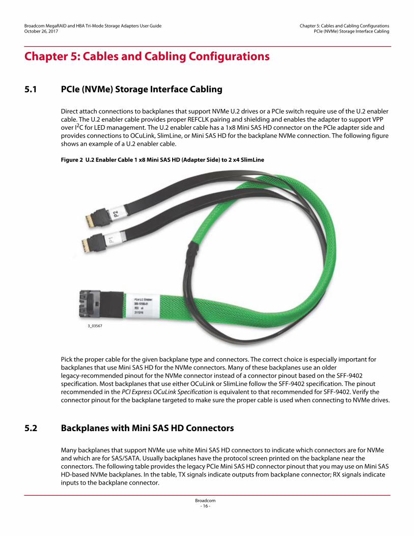
Direct attach connections to backplanes that support NVMe U.2 drives or a PCIe switch require use of the U.2 enabler cable. The U.2 enabler cable provides proper REFCLK pairing and shielding and enables the adapter to support VPP over I2C for LED management. The U.2 enabler cable has a 1x8 Mini SAS HD connector on the PCIe adapter side and provides connections to OCuLink, SlimLine, or Mini SAS HD for the backplane NVMe connection. The following figure shows an example of a U.2 enabler cable.
Figure 2 U.2 Enabler Cable 1 x8 Mini SAS HD (Adapter Side) to 2 x4 SlimLine
Pick the proper cable for the given backplane type and connectors. The correct choice is especially important for backplanes that use Mini SAS HD for the NVMe connectors. Many of these backplanes use an older legacy-recommended pinout for the NVMe connector instead of a connector pinout based on the SFF-9402 specification. Most backplanes that use either OCuLink or SlimLine follow the SFF-9402 specification. The pinout recommended in the PCI Express OCuLink Specification is equivalent to that recommended for SFF-9402. Verify the connector pinout for the backplane targeted to make sure the proper cable is used when connecting to NVMe drives.
5.2 Backplanes with Mini SAS HD Connectors
Many backplanes that support NVMe use white Mini SAS HD connectors to indicate which connectors are for NVMe and which are for SAS/SATA. Usually backplanes have the protocol screen printed on the backplane near the connectors. The following table provides the legacy PCIe Mini SAS HD connector pinout that you may use on Mini SAS HD-based NVMe backplanes. In the table, TX signals indicate outputs from backplane connector; RX signals indicate inputs to the backplane connector.
3_03567

Broadcom- 17 -
Broadcom MegaRAID and HBA Tri-Mode Storage Adapters User GuideOctober 26, 2017
Chapter 5: Cables and Cabling ConfigurationsBackplanes with OCuLink or SlimLine Connectors
NOTE The pinout in this table is not the pinout used on the Broadcom Tri-Mode storage adapter. For Tri-Mode versatility (for SAS and NVMe support), the adapters follow the SFF-9402 pinout.
5.3 Backplanes with OCuLink or SlimLine Connectors
OCuLink or SlimLine are the preferred connectors to use for NVMe backplane connectors. This approach enables a straightforward keying mechanism to prevent connecting NVMe drives with standard 12Gb/s SAS cables.
Backplanes that use OCuLink connectors should follow the PCI Express OCuLink Specification. This pinout is also equivalent to the SFF-9402 specification recommendations. Verify the backplane connector pinout to make sure you use proper cabling to the NVMe drive. Refer to the PCI Express OCuLink Specification and the SFF-9402 specification for backplane NVMe connector pinout information.
Table 10 Legacy PCIe over Mini SAS HD Backplane Connector Pinout
Pin Description Pin Description
D1 BMC_SMB_CLK B1 GND
D2 BMC_SMB_DAT B2 PE_RST_N
D3 GND B3 GND
D4 TX0_P B4 RX0_P
D5 TX0_N B5 RX0_N
D6 GND B6 GND
D7 TX2_P B7 RX2_P
D8 TX2_N B8 RX2_N
D9 GND B9 GND
C1 CPU_SMB_CLK A1 PCIE_CLK_100M_N
C2 CPU_SMB_DAT A2 PCIE_CLK_100M_P
C3 GND A3 GND
C4 TX1_P A4 RX1_P
C5 TX1_N A5 RX1_N
C6 GND A6 GND
C7 TX3_P A7 RX3_P
C8 TX3_N A8 RX3_N
C9 GND A9 GND

Broadcom- 18 -
Broadcom MegaRAID and HBA Tri-Mode Storage Adapters User GuideOctober 26, 2017
Chapter 6: Configuration ScenariosSAS/SATA Connect
Chapter 6: Configuration Scenarios
The following section describes the various configuration scenarios for the internal port count boards. This list of scenarios is not exhaustive, but it shows some different available options. Each scenario includes a view of the cabling between the adapter and the mid-plane.
6.1 SAS/SATA Connect
The Tri-Mode storage adapters support connections to SAS/SATA drives or SAS expanders using standard 12Gb/s SAS cables. The adapter supports connections to both single-ported and dual-ported SAS drives. See Section 3.1, SAS/SATA Support, for more information on using wide port SAS connections on 16-port adapters.
The following figure shows a typical direct-attach SAS/SATA configuration. Using expanders, you can increase the number of drives attached to a single adapter.
Figure 3 Standard 12Gb/s SAS Cable Attach

Broadcom- 19 -
Broadcom MegaRAID and HBA Tri-Mode Storage Adapters User GuideOctober 26, 2017
Chapter 6: Configuration Scenariosx2 NVMe Direct Attach
6.2 x2 NVMe Direct Attach
The following figure shows eight x2 NVMe drives that attach directly to the adapter. Each drive must be connected using adjacent lanes and stay within the same PDB. See Section 3.2, PCIe (NVMe) Support, for more information on PDB and connector arrangement. Design the backplane NVMe connectors based on the SFF-9402 pinout standard and use the available U.2 enabler cables described in Chapter 5, Cables and Cabling Configurations, to avoid improper connection scenarios.
One REFCLK is supplied per connector. To directly attach x2 NVMe where more than one drive is sourced from a single connector, take care to properly fan-out the shared REFCLK on the backplane.
Figure 4 Connecting x2 NVMe Drives with U.2 Enabler Cables
6.3 x4 NVMe Direct Attach
The following figure shows attaching four x4 NVMe drives directly to the adapter. Each drive must be connected using adjacent lanes and stay within the same PDB. Connector 0 and Connector 1 can connect to two x4 NVMe drives, and Connector 2 and Connector 3 can connector to two x4 NVMe drives. See Table 5, Board Lanes-to-PDB Core Associations, for more information on PDB and connect arrangement. Design the backplane NVMe connectors based on the SFF-9402 pinout standard and use the available U.2 enabler cables described in Chapter 5, Cables and Cabling Configurations, to avoid improper connection scenarios.

Broadcom- 20 -
Broadcom MegaRAID and HBA Tri-Mode Storage Adapters User GuideOctober 26, 2017
Chapter 6: Configuration Scenariosx4 NVMe and x1 SAS Direct Attach
Figure 5 x4 NVMe Direct Attach with U.2 Enabler Cables
6.4 x4 NVMe and x1 SAS Direct Attach
The following figure shows two x4 NVMe drives and eight x1 SAS that attach directly to the adapter. The x4 NVMe drives require use of the U.2 enabler cable described in Chapter 5, Cables and Cabling Configurations, and the SAS drives use standard 12Gb/s SAS cables. Each x4 NVMe drive must be connected using adjacent lanes within a single PDB. The figure shows using Connector 0 and Connector 1 for the NVMe connections and Connector 2 and Connector 3 for the SAS connections. This arrangement can be reversed, so that Connector 2 and Connector 3 are used for the NVMe connections and Connector 0 and Connector 1 are used for the SAS connections.
Figure 6 x4 NVMe and x1 SAS Direct Attach

Broadcom- 21 -
Broadcom MegaRAID and HBA Tri-Mode Storage Adapters User GuideOctober 26, 2017
Chapter 7: CacheVault Data Protection
Chapter 7: CacheVault Data Protection
The MegaRAID Tri-Mode storage adapters support data retention by using NAND flash memory down on the adapter, backed up by a CacheVault Power Module 05 (CVPM05).
NOTE The MegaRAID 9440-8i Tri-Mode storage adapter and the HBAs do not support CacheVault data protection.
The CVPM05 module is a super-capacitor pack that provides power for the backup of your data in case of host power loss or server failure. The CVPM05 module connects to the controller remotely by cable. The data is backed up to the NAND flash memory available on the MegaRAID storage adapter.
In the event of host power loss or server failure, any data available in the cache is offloaded to the on-board NAND memory. During this process, the CVPM03 power module powers the necessary components needed for offload.
NOTE You cannot hot-plug CVPM05 modules. Removing or inserting a CVPM05 module with the adapter powered on might damage the board and the super-capacitor functionality. To attach or remove a CVPM05 module from an adapter, you must fully power down the adapter before you attach the module to or remove the module from its mating connector.
For more information on installation of the CVPM05 module, refer to the CacheVault Power Module 05 (CVPM05) Getting Started Guide and the Cache Backup Products for MegaRAID SAS+SATA RAID Controllers User Guide available at http://www.broadcom.com/support/download-search.

Broadcom- 22 -
Broadcom MegaRAID and HBA Tri-Mode Storage Adapters User GuideOctober 26, 2017
Chapter 8: Adapter Installation Instructions
Chapter 8: Adapter Installation Instructions
This chapter provides detailed instructions on how to install your Tri-Mode storage adapter.
NOTE The figure in this section shows the installation of the MegaRAID 9480-8i8e Tri-Mode storage adapter in a PCIe slot. You can install other Tri-Mode storage adapters in the same way.
To install the adapter, follow these steps:
1. Unpack your Tri-Mode storage adapter.Unpack and remove the adapter. Inspect the adapter for damage. If it appears damaged, contact your Broadcom Technical Support.
ATTENTION To avoid the risk of data loss, back up your data before you change your system configuration.
2. Turn off the power to the system.Turn off the power to the computer, and disconnect the AC power cord. Remove the computer cover. Refer to the system documentation for instructions. Before you install the adapter, make sure that the computer is disconnected from the power and from any networks.
CAUTION Disconnect the computer from the power supply and from any networks to which you will install the adapter, or you risk damaging the system or experiencing electrical shock.
3. Review the adapter connectors.See Chapter 9, Broadcom MegaRAID and HBA Tri-Mode Storage Adapter Characteristics, for diagrams of the Tri-Mode storage adapters that show their connectors.
4. Check the mounting bracket on the adapter.If required for your system, replace the full-profile mounting bracket that ships on the adapter with the low-profile bracket supplied. Complete the following steps to attach the low-profile bracket.
a. Using a No. 1 Phillips screwdriver that is ESD safe, remove the two Phillips screws that connect the full-profile bracket to the board. Unscrew the two screws located at the top and bottom edges of the board. Avoid touching any board components with the screwdriver or the bracket.
b. Remove the full-profile bracket. Do not damage the adapter.c. Place the adapter on top of the low-profile bracket. Position the bracket so that the screw holes in the tabs
align with the openings in the board.d. Using a No. 1 Phillips torque screwdriver that is ESD safe, set to a maximum torque of 4.8 ± 0.5 inch-pounds.
Replace the two Phillips screws removed in step a.
ATTENTION Exceeding this torque specification can damage the board, connectors, or screws, and can void the warranty on the board.
ATTENTION Damage caused to the board as a result of changing the bracket can void the warranty on the board. Adapters returned without a bracket mounted on the board will be returned without return merchandise authorization (RMA) processing.
5. Insert the Tri-Mode storage adapter into an available PCIe slot. Select a PCIe slot, and align the controller’s PCIe bus connector to the slot, as shown in the following figure. Press down gently, but firmly, to make sure that the card is seated correctly in the slot. Secure the bracket to the computer chassis with the bracket screw.

Broadcom- 23 -
Broadcom MegaRAID and HBA Tri-Mode Storage Adapters User GuideOctober 26, 2017
Chapter 8: Adapter Installation Instructions
NOTE Adapters with a x8 host interface can operate in x8 or x16 slots. However, some x16 PCIe slots support only PCIe graphics cards; an adapter installed in one of these slots will not function. Refer to the guide for your motherboard for information about the PCIe slots.
Figure 7 Installing the MegaRAID 9480-8i8e Tri-Mode Storage Adapter in a PCIe Slot
6. Configure and install the SAS, SATA, and PCIe (NVMe) devices in the host computer case.Refer to documentation for the devices for any pre-installation configuration requirements.
7. Connect the Tri-Mode storage adapter to the devices.For SAS/SATA connections, connect standard 12Gb/s SAS cables with an internal Mini SAS HD connector on one end to connect to the controller and the appropriate connector on the other end to attach to the backplane or SAS/SATA devices.
For PCIe (NVMe) connections, special cables are needed depending on the type of NVMe drive in use. The adapter connector's pin definitions follow the SFF-9402 specification and cables must support this connector pin definition. For more information on types of cables needed for NVMe connectivity, see Chapter 5, Cables and Cabling Configurations.
CAUTION For NVMe connections to a SFF-8639 (U.2) bay or connections to a PCIe switch, use only approved cables with REFCLK forwarded on the proper pins. Improperly connecting a standard 12Gb/s SAS cable to a SFF-8639 bay could damage the PCIe storage adapter and the drive.
The maximum cable length is 1 meter (39.37 in.). A single wide port SAS or multi-lane PCIe (NVMe) device cannot connect to phys controlled by different SAS cores or PDBs. See Chapter 3, Tri-Mode Storage Interface, for more information.
8. Provide the required airflow for the installed adapter. See Section 10.1, Operating and Nonoperating Conditions, to find the adapter’s cooling requirements.
Edge of Motherboard
PCIe Slot
Bracket Screw
Press Here
Press Here
3_03254

Broadcom- 24 -
Broadcom MegaRAID and HBA Tri-Mode Storage Adapters User GuideOctober 26, 2017
Chapter 8: Adapter Installation Instructions
9. Turn on the power to the system.Reinstall the computer cover, and reconnect the AC power cords. Make sure that the power is turned on to the storage devices before or at the same time that the power is turned on to the host computer. Turn on power to the host computer. If the computer is powered on before these devices, the devices might not be recognized.
During boot, a BIOS message appears. The firmware takes several seconds to initialize. The configuration utility prompt times out after several seconds. The second portion of the BIOS message shows the adapter controller number, firmware version, and cache SDRAM size. The numbering of the controllers follows the PCI slot scanning order used by the host motherboard.
10. Choose the correct storage profile.The adapters can run in different profiles to enable storage interface connections to SAS/SATA only, PCIe only, or mixed (SAS/SATA and PCIe). The default firmware loaded on the HBAs enables mixed-mode operation. You can download the SAS/SATA only profile for the HBAs from Support and Download center at http://www.broadcom.com/support/download-search.
The MegaRAID adapters support the following three basic modes or profiles of operation for the storage interface:
— SAS/SATA only mode— NVMe only mode— Mixed mode
Refer to the 12Gb/s MegaRAID SAS Software User Guide for a complete list of supported profiles. Each profile is set through StorCLI or Human Interface Infrastructure (HII). The default mode is the SAS/SATA only profile.
StorCLI: Use the following two commands to perform profile ID management on StorCLI:
— storcli /cx show profile— storcli /cx set profile profileid=
After you set the new profile, reboot the system for the changes to take effect.
HII:a. Enter HII during boot of the MegaRAID controller.b. Select Main Menu > Controller Management > Advanced Controller Properties > Profile Management.c. Use arrow keys to move down to Profile ID, then press Enter.

Broadcom- 25 -
Broadcom MegaRAID and HBA Tri-Mode Storage Adapters User GuideOctober 26, 2017
Chapter 8: Adapter Installation Instructions
A pop-up window displays possible Profile IDs, as shown in the following figure.
Figure 8 Use the HII Configuration Utility to Display and Set the Adapter Profile
d. From the popup, select the new profile, then press Enter.e. Reboot the system for the changes to take effect.f. Run the HII Configuration Utility.
Run the HII configuration utility to configure the drive groups and virtual drives. Refer to the 12Gb/s MegaRAID SAS Software User Guide for detailed steps on drive configuration.
11. Install the operating system driver.The Tri-Mode storage adapters can operate under various operating systems. To operate under these operating systems, you must install the software drivers. The firmware and drivers are routinely updated and made available on the Support and Download center. Visit http://www.broadcom.com/support/download-search and download the latest firmware and driver for the controller.
The hardware installation of your Tri-Mode storage adapter is complete.

Broadcom- 26 -
Broadcom MegaRAID and HBA Tri-Mode Storage Adapters User GuideOctober 26, 2017
Chapter 9: Broadcom MegaRAID and HBA Tri-Mode Storage Adapter CharacteristicsMegaRAID 9460-16i Adapter – Connector and LED Designations
Chapter 9: Broadcom MegaRAID and HBA Tri-Mode Storage Adapter Characteristics
9.1 MegaRAID 9460-16i Adapter – Connector and LED Designations
The MegaRAID 9460-16i Tri-Mode storage adapter is a 6.127 in. × 2.712 in. (155.65 mm × 68.90 mm) board. The component height on the top and bottom of the adapter complies with the PCIe specification. This section provides the connector and LED designations for the MegaRAID 9460-16i Tri-Mode storage adapter.
The following figure shows the connectors and LED locations on the MegaRAID 9460-16i Tri-Mode storage adapter. Pin 1 on the headers and connectors is highlighted in red in the figure.
Figure 9 Card Layout for the MegaRAID 9460-16i Tri-Mode Storage Adapter
The following table describes the headers and connectors on the MegaRAID 9460-16i Tri-Mode storage adapter.
Table 11 Headers and Connectors
Connector Type Description
J2 Standard edge card connector The interface between the storage adapter and the host system.With the PCIe interface, this connector provides power to the board and an I2C interface connected to the I2C bus for the Intelligent Platform Management Interface (IPMI).
J4 Default serial boot ROM (SBR) header 2-pin connector.Reserved for Broadcom use.
J7 Advanced software options hardware key header
2-pin header (middle pin is not populated).Enables support for selected advanced features.
J8 On-board Serial Universal Asynchronous Receiver/Transmitter (UART) connector
4-pin connector.Reserved for Broadcom use.
J10 Global hard disk drive (HDD) activity LED header
2-pin connector.Connects to an LED that indicates activity on the drives connected to the controller.

Broadcom- 27 -
Broadcom MegaRAID and HBA Tri-Mode Storage Adapters User GuideOctober 26, 2017
Chapter 9: Broadcom MegaRAID and HBA Tri-Mode Storage Adapter CharacteristicsMegaRAID 9460-8i Adapter – Connector and LED Designations
The following table describes the LEDs on the Tri-Mode storage adapter.
9.2 MegaRAID 9460-8i Adapter – Connector and LED Designations
The MegaRAID 9460-8i Tri-Mode storage adapter is a 6.127 in. × 2.712 in. (155.65 mm × 68.90 mm) board. The component height on the top and bottom of the adapter complies with the PCIe specification. This section provides the connector and LED designations for the MegaRAID 9460-8i Tri-Mode storage adapter.
The following figure shows the connector and LED locations on the MegaRAID 9460-8i Tri-Mode storage adapter. Pin 1 on the headers and connectors is highlighted in red in the figure.
Figure 10 Card Layout for the MegaRAID 9460-8i Tri-Mode Storage Adapter
The following table describes the headers and connectors on the MegaRAID 9460-8i Tri-Mode storage adapter.
J11 Global drive fault LED header 2-pin connector.Connects to an LED that indicates whether a drive is in a fault condition.
J14 CacheVault power module interface 9-pin connector.Connects the adapter to a CacheVault power module.
J15 Storage interface connectors Four SFF-8643 Mini-SAS HD 4-port internal connectors.Connects the adapter by cable to the storage devices.
Table 12 LED Designations
LED Type Description
LED 2 Yellow RoC over temperature Stays on solid to indicate that the SAS3516 device temperature sensor is over the temperature threshold. When the device is in the proper temperature range, this LED is off.
LED 3 Green system heartbeat Indicates that the SAS3516 RoC ASIC is operating normally. This LED blinks at 1 Hz.
LED 4 Green dirty cache Indicates the cache is dirty, that is, not yet saved to the storage devices.
LED 5 Yellow supercap fault Indicates that the CacheVault power module is in fault state or is over temperature.
LED 6 Green Open NAND Flash Interface (ONFI) activity
Indicates when the ONFI is active for cache offload or recovery.
Table 11 Headers and Connectors (Continued)
Connector Type Description
J7

Broadcom- 28 -
Broadcom MegaRAID and HBA Tri-Mode Storage Adapters User GuideOctober 26, 2017
Chapter 9: Broadcom MegaRAID and HBA Tri-Mode Storage Adapter CharacteristicsMegaRAID 9480-8i8e Adapter – Connector and LED Designations
The following table describes the LEDs on the storage adapter.
9.3 MegaRAID 9480-8i8e Adapter – Connector and LED Designations
The MegaRAID 9480-8i8e Tri-Mode storage adapter is a 6.600 in. × 2.712 in. (167.65 mm × 68.90 mm) board. The component height on the top and bottom of the adapter complies with the PCIe specification. This section provides the board connector and LED designations for the MegaRAID 9480-8i8e Tri-Mode storage adapter.
The following figure shows the connector and LED locations on the MegaRAID 9480-8i8e Tri-Mode storage adapter. Pin 1 on the headers and connectors is highlighted in red in the figure.
Table 13 Headers and Connectors
Connector Type Description
J2 Standard edge card connector The interface between the storage adapter and the host system.With the PCIe interface, this connector provides power to the board and an I2C interface connected to the I2C bus for the IPMI.
J4 Default SBR header 2-pin connector.Reserved for Broadcom use.
J7 Advanced software options hardware key header
2-pin header (middle pin is not populated).Enables support for selected advanced features.
J8 On-board serial UART connector 4-pin connector.Reserved for Broadcom use.
J10 Global HDD activity LED header 2-pin connector.Connects to an LED that indicates activity on the drives connected to the controller.
J11 Global drive fault LED header 2-pin connector.Connects to an LED that indicates whether a drive is in a fault condition.
J14 CacheVault power module interface 9-pin connector.Connects the storage adapter to a CacheVault power module.
J15 Storage interface connectors Two SFF-8643 Mini-SAS HD 4-port internal connectors.Connects the controller by cable to the storage devices.
Table 14 LED Designations
LED Type Description
LED 2 Yellow RoC over temperature Stays on solid to indicate that the SAS3508 device temperature sensor is over the temperature threshold. When the device is in the proper temperature range, this LED is off.
LED 3 Green system heartbeat Indicates that the SAS3508 RoC ASIC is operating normally. This LED blinks at 1 Hz.
LED 4 Green dirty cache Indicates the cache is dirty, that is, not yet saved to the storage devices.
LED 5 Yellow supercap fault Indicates that the CacheVault power module is in fault state or is over temperature.
LED 6 Green ONFI activity Indicates when the ONFI is active for cache offload or recovery.

Broadcom- 29 -
Broadcom MegaRAID and HBA Tri-Mode Storage Adapters User GuideOctober 26, 2017
Chapter 9: Broadcom MegaRAID and HBA Tri-Mode Storage Adapter CharacteristicsMegaRAID 9480-8i8e Adapter – Connector and LED Designations
Figure 11 Card Layout for the MegaRAID 9480-8i8e Tri-Mode Storage Adapter
The following table describes the headers and connectors on the MegaRAID 9480-8i8e Tri-Mode storage adapter.
The following table describes the LEDs on the storage adapter.
Table 15 Headers and Connectors
Connector Type Description
J2 Standard edge card connector The interface between the adapter and the host system.With the PCIe interface, this connector provides power to the board and an I2C interface connected to the I2C bus for the IPMI.
J4 Mode select header 2-pin connector.Reserved for Broadcom use.
J7 Advanced software options hardware key header
2-pin header (middle pin not populated).Enables support for selected advanced features.
J8 On-board serial UART connector 4-pin connector.Reserved for Broadcom use.
J10 Global HDD activity LED header 2-pin connector.Connects to an LED that indicates activity on the drives connected to the controller.
J11 Global drive fault LED header 2-pin connector.Connects to an LED that indicates activity on the drives connected to the controller.
J14 CacheVault power module interface 9-pin connector.Connects the storage adapter to a super-capacitor to provide power to back up your data in case of host power loss or server failure.
J15 Storage interface connectors Two SFF-8643 Mini-SAS HD internal connectors.Connects the adapter by cable to the storage devices.
Storage interface connectors Two SFF-8644 Mini-SAS HD external connectors.Connects the adapter by cable to the storage devices.

Broadcom- 30 -
Broadcom MegaRAID and HBA Tri-Mode Storage Adapters User GuideOctober 26, 2017
Chapter 9: Broadcom MegaRAID and HBA Tri-Mode Storage Adapter CharacteristicsMegaRAID SAS 9440-8i Adapter – Connector and LED Designations
9.4 MegaRAID SAS 9440-8i Adapter – Connector and LED Designations
The MegaRAID 9440-8i Tri-Mode storage adapter is a 6.127 in. × 2.712 in. (155.65 mm × 68.90 mm) board. The component height on the top and bottom of the adapter complies with the PCIe specification. This section provides the board connector and LED designations for the MegaRAID 9440-8i Tri-Mode storage adapter.
The following figure shows the connector and LED locations on the MegaRAID 9440-8i Tri-Mode storage adapter. Pin 1 on the headers and connectors is highlighted in red in the figure.
Figure 12 Card Layout for the MegaRAID 9440-8i Tri-Mode Storage Adapter
The following table describes the headers and connectors on the MegaRAID 9440-8i Tri-Mode storage adapter.
Table 16 LED Designations
LED Type Description
LED 2 Yellow RoC over temperature Stays on solid to indicate that the SAS3508 device temperature sensor is over the temperature threshold. When the device is in the proper temperature range, this LED is off.
LED 3 Green system heartbeat Indicates that the SAS3508 RoC ASIC is operating normally. This LED blinks at 1 Hz.
LED 4 Green dirty cache Indicates the cache is dirty, that is, not yet saved to the storage devices.
LED 5 Yellow supercap fault Indicates that the CacheVault power module is in fault state or is over temperature.
LED 6 Green ONFI activity Indicates when the ONFI is active for cache offload or recovery.
Table 17 Headers and Connectors
Connector Type Description
J2 Standard edge card connector The interface between the adapter and the host system.With the PCIe interface, this connector provides power to the board and an I2C interface connected to the I2C bus for the IPMI.
J3 Global drive fault LED header 2-pin connector.Connects to an LED that indicates activity on the drives connected to the controller.
J4 Default SBR header 2-pin connector.Reserved for Broadcom use.
J5 Storage interface connectors Two SFF-8643 mini-SAS HD-4i internal connectors.Connects the adapter by cable to the storage devices.

Broadcom- 31 -
Broadcom MegaRAID and HBA Tri-Mode Storage Adapters User GuideOctober 26, 2017
Chapter 9: Broadcom MegaRAID and HBA Tri-Mode Storage Adapter CharacteristicsHBA 9400-16i Adapter – Connector and LED Designations
The following table describes the LEDs on the storage adapter.
9.5 HBA 9400-16i Adapter – Connector and LED Designations
The HBA 9400-16i Tri-Mode storage adapter is a a 6.127 in. × 2.712 in. (155.65 mm × 68.90 mm) board. The component height on the top and bottom of the HBA complies with the PCIe specification. This section provides the board connector and LED designations for the HBA 9400-16i Tri-Mode storage adapter.
The following figure shows the HBA board layout for the HBA 9400-16i Tri-Mode storage adapter. Pin 1 is highlighted in red in the figure.
Figure 13 Card Layout of the HBA SAS 9400-16i Tri-Mode Storage Adapter
The following table describes the connectors on the HBA 9400-16i Tri-Mode storage adapter.
J6 Global HDD activity LED header 2-pin connector.Connects to an LED that indicates activity on the drives connected to the controller.
J7 RAID premium key feature header 3-pin header.Enables support for selected advanced features.
J8 On-board serial UART connector 4-pin port.Reserved for Broadcom use.
Table 18 LED Designations
LED Type Description
LED 1 Green Programmable System-on-Chip (PSoC) heartbeat LED
Indicates that the PSoC is operating normally.
LED 2 Yellow IOC over temperature Stays on solid to indicate that the SAS3408 device temperature sensor is over the temperature threshold. When the device is in the proper temperature range, this LED is off.
LED3 Green system heartbeat Indicates that the SAS3408 IOC is operating normally.
Table 17 Headers and Connectors (Continued)
Connector Type Description
C0
C1
C2
C3

Broadcom- 32 -
Broadcom MegaRAID and HBA Tri-Mode Storage Adapters User GuideOctober 26, 2017
Chapter 9: Broadcom MegaRAID and HBA Tri-Mode Storage Adapter CharacteristicsHBA 9400-8i Adapter – Connector and LED Designations
The following table describes the LEDs on the storage adapter.
9.6 HBA 9400-8i Adapter – Connector and LED Designations
The HBA 9400-8i Tri-Mode storage adapter is a 6.127 in. × 2.712 in. (155.65 mm × 68.90 mm) board. The component height on the top and bottom of the HBA complies with the PCIe specification. This section provides the board connector and LED designations for the HBA 9400-8i Tri-Mode storage adapter.
The following figure shows the connector and LED locations for the HBA 9400-8i Tri-Mode storage adapter. Pin 1 is highlighted in red in the figure.
Figure 14 Card Layout of the HBA SAS 9400-8i Tri-Mode Storage Adapter
The following table describes the connectors on the HBA 9400-8i Tri-Mode storage adapter.
Table 19 Connectors
Connector Type Description
J2 Standard board edge connector PCIe x8 board edge connector.
With the PCIe interface, this connector provides power to the board and an I2C interface connected to the I2C bus for the IPMI.
J4 Mode select header 2-pin connector.Reserved for Broadcom use.
J5 Storage interface connectors Four SFF-8643 Mini SAS HD internal connectors.Connects the adapter by cable to storage devices.
J8 On-board serial UART connector 4-pin connector.Reserved for Broadcom use.
Table 20 LED Designations
LED Type Description
LED 1 Green PSoC heartbeat LED Indicates that the PSoC is operating normally.
LED 2 Yellow IOC over temperature Stays on solid to indicate that the SAS3416 device temperature sensor is over the temperature threshold. When the device is in the proper temperature range, this LED is off.
LED3 Green system heartbeat Indicates that the SAS3416 IOC is operating normally.
Broadcom- 33 -
Broadcom MegaRAID and HBA Tri-Mode Storage Adapters User GuideOctober 26, 2017
Chapter 9: Broadcom MegaRAID and HBA Tri-Mode Storage Adapter CharacteristicsHBA 9400-16e Adapter – Connector and LED Designations
The following table describes the LEDs on the storage adapter.
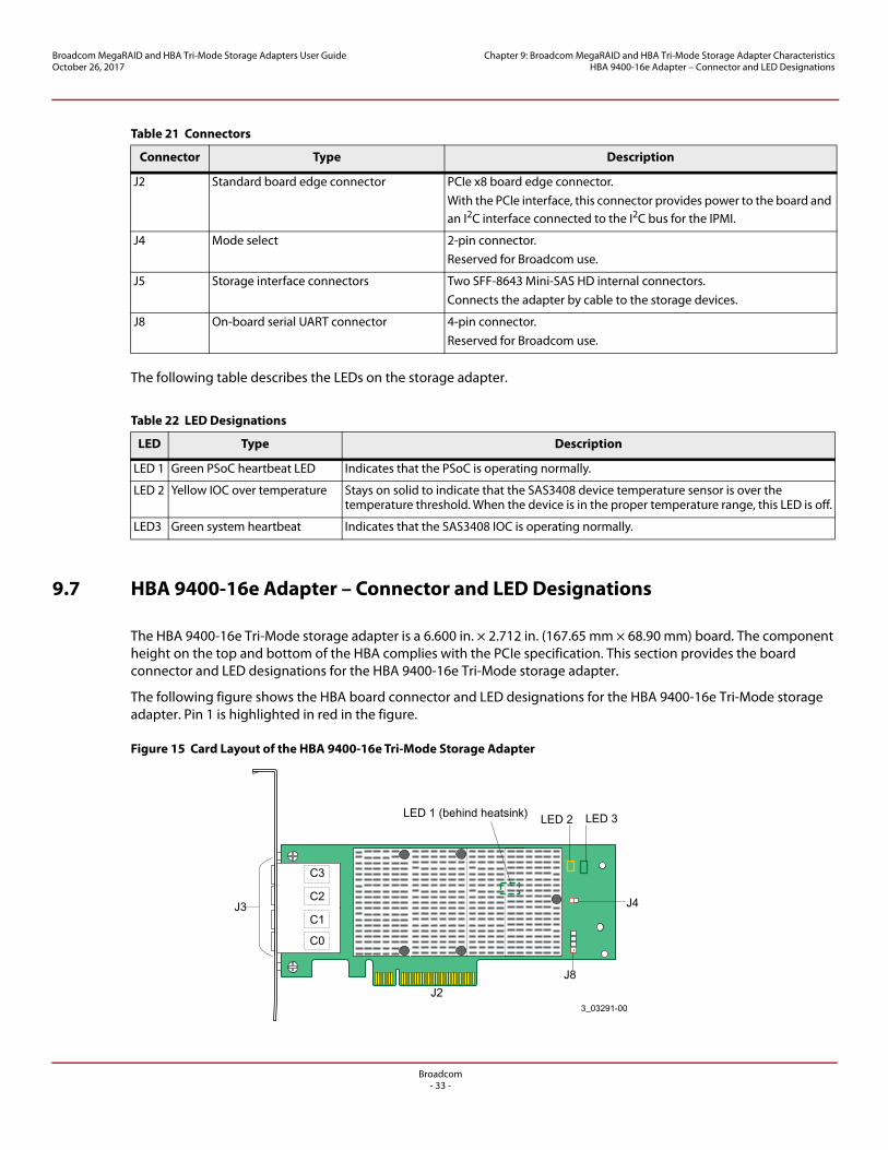
9.7 HBA 9400-16e Adapter – Connector and LED Designations
The HBA 9400-16e Tri-Mode storage adapter is a 6.600 in. × 2.712 in. (167.65 mm × 68.90 mm) board. The component height on the top and bottom of the HBA complies with the PCIe specification. This section provides the board connector and LED designations for the HBA 9400-16e Tri-Mode storage adapter.
The following figure shows the HBA board connector and LED designations for the HBA 9400-16e Tri-Mode storage adapter. Pin 1 is highlighted in red in the figure.
Figure 15 Card Layout of the HBA 9400-16e Tri-Mode Storage Adapter
Table 21 Connectors
Connector Type Description
J2 Standard board edge connector PCIe x8 board edge connector.With the PCIe interface, this connector provides power to the board and an I2C interface connected to the I2C bus for the IPMI.
J4 Mode select 2-pin connector.Reserved for Broadcom use.
J5 Storage interface connectors Two SFF-8643 Mini-SAS HD internal connectors.Connects the adapter by cable to the storage devices.
J8 On-board serial UART connector 4-pin connector.Reserved for Broadcom use.
Table 22 LED Designations
LED Type Description
LED 1 Green PSoC heartbeat LED Indicates that the PSoC is operating normally.
LED 2 Yellow IOC over temperature Stays on solid to indicate that the SAS3408 device temperature sensor is over the temperature threshold. When the device is in the proper temperature range, this LED is off.
LED3 Green system heartbeat Indicates that the SAS3408 IOC is operating normally.

Broadcom- 34 -
Broadcom MegaRAID and HBA Tri-Mode Storage Adapters User GuideOctober 26, 2017
Chapter 9: Broadcom MegaRAID and HBA Tri-Mode Storage Adapter CharacteristicsHBA 9400-8e Adapter – Connector and LED Designations
The following table describes the connectors on the HBA 9400-16e Tri-Mode storage adapter.
The following table describes the LEDs on the storage adapter.
9.8 HBA 9400-8e Adapter – Connector and LED Designations
The HBA 9400-8e Tri-Mode storage adapter is a 6.600 in. × 2.712 in. (167.65 mm × 68.90 mm) board. The component height on the top and bottom of the HBA complies with the PCIe specification. This section provides the board connector and LED designations for the HBA 9400-8e Tri-Mode storage adapter.
The following figure shows the connectors and LED designations on the HBA 9400-8e Tri-Mode storage adapter. Pin 1 is highlighted in red in the figure.
Figure 16 Card Layout of the HBA 9400-8e Tri-Mode Storage Adapter
Table 23 Connectors
Connector Type Description
J2 Standard board edge connector PCIe x8 board edge connector.With the PCIe interface, this connector provides power to the board and an I2C interface connected to the I2C bus for the IPMI.
J3 Storage interface connectors Four SFF-8644 Mini SAS HD external connectors.Connects the adapter by cable to the storage devices.
J4 Mode select 2-pin connector.Reserved for Broadcom use.
J8 On-board Serial UART connector 4-pin connector.Reserved for Broadcom use.
Table 24 LED Designations
LED Type Description
LED 1 Green PSoC heartbeat LED Indicates that the PSoC is operating normally.
LED 2 Yellow IOC over temperature Stays on solid to indicate that the SAS3416 device temperature sensor is over the temperature threshold. When the device is in the proper temperature range, this LED is off.
LED3 Green system heartbeat Indicates that the SAS3416 IOC is operating normally.

Broadcom- 35 -
Broadcom MegaRAID and HBA Tri-Mode Storage Adapters User GuideOctober 26, 2017
Chapter 9: Broadcom MegaRAID and HBA Tri-Mode Storage Adapter CharacteristicsHBA 9400-8i8e Adapter – Connector and LED Designations
The following table describes the headers and connectors on the HBA 9400-8e Tri-Mode storage adapter.
9.9 HBA 9400-8i8e Adapter – Connector and LED Designations
The HBA 9400-8i8e Tri-Mode storage adapter is a 6.600 in. × 2.712 in. (167.65 mm × 68.90 mm) board. The component height on the top and bottom of the HBA complies with the PCIe specification. This section provides the board connector and LED designations for the adapter.
The following figure shows the connectors and LED designations on the HBA 9400-8i8e Tri-Mode storage adapter. Pin 1 is highlighted in red in the figure.
Figure 17 Board Layout for the HBA 9400-8i8e Tri-Mode Storage Adapter
The following table describes the headers and connectors on the HBA 9400-8i8e Tri-Mode storage adapter.
Table 25 Headers and Connectors
Connector Type Description
J2 Standard board edge connector PCIe x8 board edge connector.With the PCIe interface, this connector provides power to the board and an I2C interface connected to the I2C bus for the IPMI.
J3 Storage interface connectors Two SFF-8644 Mini SAS HD external connectors.Connects the adapter by cable to the storage devices.
J4 Mode select 2-pin connector.Reserved for Broadcom use.
J8 On-board serial UART connector 4-pin connector.Reserved for Broadcom use.

Broadcom- 36 -
Broadcom MegaRAID and HBA Tri-Mode Storage Adapters User GuideOctober 26, 2017
Chapter 9: Broadcom MegaRAID and HBA Tri-Mode Storage Adapter CharacteristicsHBA 9405W-16i Adapter – Connector and LED Designations
The following table describes the LEDs on the storage adapter.
9.10 HBA 9405W-16i Adapter – Connector and LED Designations
The HBA 9405W-16i Tri-Mode storage adapter is a 6.600 in. × 2.712 in. (167.65 mm × 68.90 mm) board. The component height on the top and bottom of the HBA complies with the PCIe specification. This section provides the board connector and LED designations for the storage adapter.
The following figure shows the connectors and LED designations on the HBA 9405W-16i Tri-Mode storage adapter. Pin 1 on the connectors is highlighted in red in the figure.
Figure 18 Card Layout of the HBA 9405W-16i Tri-Mode Storage Adapter
The following table describes the connectors on the HBA 9405W-16i Tri-Mode storage adapter.
Table 26 Headers and Connectors
Connector Type Description
J2 Standard edge card connector The interface between the adapter and the host system.
With the PCIe interface, this connector provides power to the board and an I2C interface connected to the I2C bus for the IPMI.
J4 Mode select header 2-pin connector.Reserved for Broadcom use.
J8 On-board serial UART connector 4-pin connector.Reserved for Broadcom use.
J15 Storage interface connectors Two SFF-8643 Mini-SAS HD internal connectors.Connects the adapter by cable to the storage devices.
Storage interface connectors Two SFF-8644 Mini-SAS HD external connectors.Connects the adapter by cable to the storage devices.
Table 27 LED Designations
LED Type Description
LED 2 Yellow RoC over temperature Stays on solid to indicate that the SAS3516 device temperature sensor is over the temperature threshold. When the device is in the proper temperature range, this LED is off.
LED 3 Green system heartbeat Indicates that the SAS3516 RoC ASIC is operating normally.

Broadcom- 37 -
Broadcom MegaRAID and HBA Tri-Mode Storage Adapters User GuideOctober 26, 2017
Chapter 9: Broadcom MegaRAID and HBA Tri-Mode Storage Adapter CharacteristicsHBA 9405W-16e Adapter – Connector and LED Designations
The following table describes the LEDs on the storage adapter.
9.11 HBA 9405W-16e Adapter – Connector and LED Designations
The HBA 9405W-16e Tri-Mode storage adapter is a 6.600 in. × 2.712 in. (167.65 mm × 68.90 mm) board. The component height on the top and bottom of the HBA complies with the PCIe specification. This section provides the board connector and LED designations for the storage adapter.
The following figure shows the connectors and LED designations on the HBA 9405W-16e Tri-Mode storage adapter. Pin 1 on the connectors is highlighted in red in the figure.
Figure 19 Card Layout of the HBA 9405W-16e Tri-Mode Storage Adapter
Table 28 Connectors
Connector Type Description
J2 Standard board edge connector PCIe x8 board edge connector.With the PCIe interface, this connector provides power to the board and an I2C interface connected to the I2C bus for the IPMI.
J5 Storage interface connectors Four SFF-8643 Mini SAS HD internal connectors.Connects the adapter by cable to the storage devices.
J4 Mode select 2-pin connector.Reserved for Broadcom use.
J8 On-board Serial UART connector 4-pin connector.Reserved for Broadcom use.
Table 29 LED Designations
LED Type Description
LED 1 Green PSoC heartbeat LED Indicates that the PSoC is operating normally.
LED 2 Yellow IOC over temperature Stays on solid to indicate that the SAS3616W device temperature sensor is over the temperature threshold. When the device is in the proper temperature range, this LED is off.
LED3 Green system heartbeat Indicates that the SAS3616W IOC is operating normally.

Broadcom- 38 -
Broadcom MegaRAID and HBA Tri-Mode Storage Adapters User GuideOctober 26, 2017
Chapter 9: Broadcom MegaRAID and HBA Tri-Mode Storage Adapter CharacteristicsHBA 9405W-16e Adapter – Connector and LED Designations
The following table describes the connectors on the HBA 9405W-16e Tri-Mode storage adapter.
The following table describes the LEDs on the storage adapter.
Table 30 Connectors
Connector Type Description
J2 Standard board edge connector PCIe x8 board edge connector.With the PCIe interface, this connector provides power to the board and an I2C interface connected to the I2C bus for the IPMI.
J3 Storage interface connectors Four SFF-8644 Mini SAS HD external connectors.Connects the adapter by cable to storage devices.
J4 Mode select 2-pin connector.Reserved for Broadcom use.
J8 On-board serial UART connector 4-pin connector.Reserved for Broadcom use.
Table 31 LED Designations
LED Type Description
LED 1 Green PSoC heartbeat LED Indicates that the PSoC is operating normally.
LED 2 Yellow IOC over temperature Stays on solid to indicate that the SAS3616W device temperature sensor is over the temperature threshold. When the device is in the proper temperature range, this LED is off.
LED3 Green system heartbeat Indicates that the SAS3616W IOC is operating normally.

Broadcom- 39 -
Broadcom MegaRAID and HBA Tri-Mode Storage Adapters User GuideOctober 26, 2017
Chapter 10: Tri-Mode Storage Adapter Technical SpecificationsOperating and Nonoperating Conditions
Chapter 10: Tri-Mode Storage Adapter Technical Specifications
10.1 Operating and Nonoperating Conditions
The following table lists the operating (thermal and atmospheric) conditions and nonoperating (such as storage and transit) environment for the storage adapters. The minimum airflow, measured as linear feet per minute (LFPM), must be met to avoid operating the controller’s processor and board components above their maximum junction temperatures.
10.2 Tri-Mode Storage Adapter Power Supply Requirements
All power is supplied to the Tri-Mode storage adapter through the PCIe 3.3V rails and the 12V rail. Onboard switching regulator circuitry that operates from the 3.3V rails and the 12V rail provides the necessary voltages. The following states describe the typical power consumption of the adapters.
Typical power is measured with maximum I/O traffic, typical silicon process material, and nominal voltages operating the card at an ambient temperature of 45°C with required airflow.
The supply voltages supplied by the PCIe edge connector are 12V ± 8% and 3.3V ± 9%.
10.2.1 MegaRAID Tri-Mode Storage Adapter Power Supply Requirements
The following table describes the typical power consumption of the MegaRAID Tri-Mode storage adapters.
Table 32 Operating and Nonoperating Conditions
Storage Adapter
Operating Conditions Nonoperating Environment
Relative Humidity Range (Noncondensing)
Minimum LFPM
Temperature Rangea
a. For adapters with a CVPM, this range applies with or without the CVFM attached.
Relative Humidity Range (Noncondensing)
Temperature Range
9460-16i 20% to 80% 250 10°C to +55°C 5% to 95% –40°C to +70°C
9460-8i 20% to 80% 250 10°C to +55°C 5% to 95% –40°C to +70°C
9480-8i8e 20% to 80% 200 10°C to +55°C 5% to 95% –40°C to +70°C
9440-8i 20% to 80% 200 10°C to +55°C 5% to 95% –40°C to +70°C
9400-16i 20% to 80% 200 10°C to +55°C 5% to 95% –40°C to +70°C
9400-8i 20% to 80% 200 10°C to +55°C 5% to 95% –40°C to +70°C
9400-16e 20% to 80% 200 10°C to +55°C 5% to 95% –40°C to +70°C
9400-8e 20% to 80% 200 10°C to +55°C 5% to 95% –40°C to +70°C
9400-8i8e 20% to 80% 200 10°C to +55°C 5% to 95% –40°C to +70°C
9405W-16i 20% to 80% 200 10°C to +55°C 5% to 90% –40°C to +70°C
9405W-16e 20% to 80% 200 10°C to +55°C 5% to 90% –40°C to +70°C

Broadcom- 40 -
Broadcom MegaRAID and HBA Tri-Mode Storage Adapters User GuideOctober 26, 2017
Chapter 10: Tri-Mode Storage Adapter Technical SpecificationsTri-Mode Storage Adapter Power Supply Requirements
10.2.2 HBA Tri-Mode Storage Adapter Power Supply Requirements
The following table describes the typical power consumption of the HBA Tri-Mode storage adapters.
Table 33 MegaRAID Tri-Mode Storage Adapter Typical Power Consumption
Power ModeTypical Power
9460-16ia
a. During the transparent learn cycle, the CacheVault power module consumes up to an additional 6W. The PCIe 3.3V rail supplies the power for the learn cycle.
9460-8ia 9480-8i8ea 9440-8i
3.3V Supply 0.28W 0.28W 0.20W 1.6W
+ 12V Supply 16.7W 13.80W 17.48W 8.42W
3.3V Auxiliary Supply 0.08W 0.08W 0.03W 0.03W
Total Power 17.06W 14.16W 17.71W 10.05W
Table 34 HBA Tri-Mode Storage Adapter Typical Power Consumption
Power ModeTypical Power
9400-16i 9400-8i 9400-16e 9400-8e 9400-8i8e 9405W-16i 9405W-16e
3.3V Supply 1.6W 1.6W 1.33W 1.33W 1.33W 1.65W 1.48W
+ 12V Supply 10.32W 8.42W 9.82W 8.12W 8.12W 12.35W 11.90W
3.3V Auxiliary Supply 0.03W 0.03W 0.03W 0.03W 0.03W 0.03W 0.44W
Total Power 11.95W 10.05W 11.18W 9.48W 9.48W 14.03W 13.82W

Broadcom- 41 -
Broadcom MegaRAID and HBA Tri-Mode Storage Adapters User GuideOctober 26, 2017
Chapter 11: Marks, Certifications, Compliance, and Safety CharacteristicsMarks, Certifications, and Compliance
Chapter 11: Marks, Certifications, Compliance, and Safety Characteristics
11.1 Marks, Certifications, and Compliance
The design and implementation of the Tri-Mode storage adapters minimize electromagnetic emissions, susceptibility to radio frequency energy, and the effects of electrostatic discharge. The Tri-Mode storage adapters show the following marks and certifications:
CE mark RCM mark FCC Self-Certification logo Canadian Compliance Statement KCC Taiwan BSMI Japan VCCI CISPR Class B
The following models comply with CSA C22.2 No. 60950-1-07 2nd Edition 2014-10, UL 60950-1 2nd Edition 2014-10-14, UL file number E257743:
MegaRAID 9460-16i (model number 50011) MegaRAID 9460-8i (model number 50011) MegaRAID 9480-8i8e (model number 50031) MegaRAID 9440-16i (model number 50008) HBA 9400-16i (model number 50008) HBA 9400-8i (model number 50008) HBA 9400-16e (model number 50013) HBA 9400-8e (model number 50013) HBA 9400-8i8e (model number 50031) HBA 9405W-16e (model number 50044) HBA 9405W-16i (model number 50047)
11.2 Safety Characteristics
All Tri-Mode storage adapters meet or exceed the requirements of UL flammability rating 94 V0. Each bare board is also marked with the supplier name or trademark, type, and UL flammability rating. For the boards installed in a PCIe bus slot, all voltages are lower than the SELV 42.4V limit.

Broadcom- 42 -
Broadcom MegaRAID and HBA Tri-Mode Storage Adapters User GuideOctober 26, 2017
Revision HistoryVersion 1.2, October 26, 2017
Revision History
Version 1.2, October 26, 2017
The following changes were made:
Added the HBA 9405W-16i Tri-Mode storage adapter to the user guide. Updated Section 5.1, PCIe (NVMe) Storage Interface Cabling, title and content. Added LED designations to Chapter 9,Broadcom MegaRAID and HBA Tri-Mode Storage Adapter Characteristics. Combined operating condition and nonoperating condition information, and removed individual subsections in
Chapter 10, Tri-Mode Storage Adapter Technical Specifications. Restructured Section 10.2, Tri-Mode Storage Adapter Power Supply Requirements. Updated HBA 9405W-16e Tri-Mode storage adapter power information. Editorial updates.
Version 1.1, August 25, 2017
The following changes were made:
Added the HBA 9400-8i8e storage adapter and the HBA9405W-16e storage adapter to the guide.
Version 1.0, March 24, 2017
Initial document release.