Embed Size (px)
Citation preview

1
BROAN™ ERVS100Part no. ERVS100S65-105 CFM (0.4 in. w.g.)
VB0248
THE FRESH AIR SOLUTION FOR SOUTHERN REGIONS
The Broan ERVS100 is an effective, balanced ventilation solution designed specifically for homes in southern regions. The ERVS100 provides a continuous supply of fresh air to the home while exhausting stale air and polluants. Plus it manages excess moisture – making it a centerpiece for tightly-constructed, energy efficient homes in hot and humid or dry climates.
• 65 to 105 CFM at 0.4 in. w.g;• Energy recovery core recovering up to 51% of the excess moisture
and up to 71% of the apparent heat or coolness;• Built-in humidity sensor limiting the ventilation during periods
of excessive outdoor humidity levels contributes to maintain a comfortable living area and mitigate the risks of mold growth;
• Exclusive bracket system providing a faster and easier installation in the ceiling, an attic or in a closet. See the Installation and User guide for more details;
• Integrates with existing forced-air furnace ducting for easy installation but runs independently to limit energy consumption related to ventilation;
• Built-in damper on fresh air supply port to prevent outdoor air infi ltration when the unit is turned off ;
• Integrated control to easily set the unit at installation.
REPAIRS AND MAINTENANCE
All parts requiring maintenance can be removed in less than 5 minutes allowing easy access for repairs. The PSC motors are permanently lubricated.
WARRANTY
The BROAN™ ERVS100 is protected by a 5-year warranty on parts only. The energy recovery core is covered by a 5-year warranty, with the original proof of purchase.
Product balancingThe ERVS100 is equipped with 2 high static pressure blowers and is factory balanced. Once installed, the ERVS100 will remain balanced (within a 10% total diff erence between the exhaust and supply airfl ows) when the static pressure diff erence between the exhaust and the supply remains below 0.2 in. w.g.No balancing dampers are required when this condition is met.
Filters- 2 washable fi lters, 20 PPI- MERV 8 optional fi lters, part V21030.
Defrosting systemUnit performs a negative defrost during 10 minutes every 20 minutes when outdoor temperature is below 14°F, and 10 minutes every 10 minutes below -4°F.
Energy Recovery CoreMaterial: Polymerized paperType: Cross fl owWarranty: 5 years
Options• Broan VTYIK1 Tandem transition
(requires an additional backdraft damper, not included)• Broan VB20W 20-minute push-button control• Broan 69V Single-Function Control, Ivory
(Dry contact standby switch)• Broan 69W Single-Function Control, White
(Dry contact standby switch)• Broan 634M black exhaust roof cap 6" with backdraft damper and
bird screen• Broan 843BL black exhaust wall cap 6" with backdraft damper and
bird screen• Broan 641 aluminum exhaust wall cap 6"• Broan 641FA aluminum inlet wall cap 6" with bird screen• Broan CVG6 interior inlet plastic grille 6"• Broan CVL6 mounting sleeve for inlet grille CVG6• Broan CVLD6 sleeve with 6" backdraft damper
Requirements and standards• Complies with the UL 1812 requirements regulating the installation
of Energy Recovery Ventilators;• HVI certifi ed;• Airfl ow and energy recovery performance tested in accordance with
CSA C439 standard.
2
Performance in hot and humid climate
VF0067
Supply air from
outdoors
82°F @ 74% RH
Exhaust to
outdoors
79°F @ 63% RH
Exhaust from
home
75°F @ 50% RH
Supply to home
78°F @ 67% RH
Performance in hot and dry climate
VF0067
Supply air from
outdoors
106°F @ 30% RH
Exhaust to
outdoors
94°F @ 36% RH
Exhaust from
home
75°F @ 50% RH
Supply to home
87°F @ 44% RH
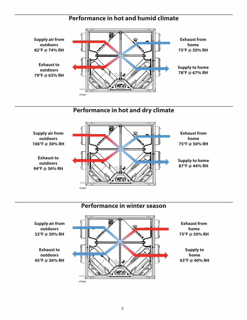
Performance in winter season
VF0066
Supply air from
outdoors
32°F @ 30% RH
Exhaust to
outdoors
45°F @ 36% RH
Exhaust from
home
75°F @ 50% RH
Supply to
home
63°F @ 40% RH

3
Noise level
0.4 sone @ 105 cfm at grille with 5’ of fl exible ducting (tested in accordance with ISO 5136 and HVI 915).
Specifi cations
Model : Broan ERVS100
Part number: ERVS100S
Total assembled weight including packaging: 40 lb.
Insulated round ports: 6" diameter
Built-in magnetic backdraft damper to close outdoor fresh air supply when the unit is turned off
Energy recovery core: -Type cross fl ow -Media membrane: Polymerized paper with aluminum
Core fi lters: 2 washable fi lters 20 PPIOptional MERV 8 fi lter kit, part no. V21030
Housing material: galvanized steel 22 ga
Door and door frame material: White pre-painted steel 20 ga
Insulation material: Molded Expanded polystyrene, UL certifi ed for Energy recovery ventilators requirements
Supply and exhaust blower motors: -PSC motors -Protection type: Thermally protected -Lock rotor electronic detection stops unit if motors failed
Installation brackets: included with the unit, allow attic, fl ush to ceiling and under-ceiling installations. Unit must be installed with the door facing upward or downward. No vertical installation allowed.
Unit electrical characteristics
-Power cord 28" with 3-prong plug
Volts Frequency Ampere Watts 120 60 hz 0.9 103Low voltage connections for optional controls energized by unit
2511/16"
91/8"
22¾"
20"FROM 20¼" TO 23"
20 7/8"1/2"
9/16"1"
TOP VIEW
EXHAUST AIR FROM HOME
SUPPLY AIR TO HOMEEXHAUST AIR TO OUTDOOR
SUPPLY AIR FROM OUTDOOR
BUILT INBACKDRAFT DAMPER
WIRES FORCONTROL CONNECTIONS
28" POWER CORD
6" PORTS(4 PORTS)
VK0102A
21 7/8"
Dimensions

4
VH0117
Closet 24" deep
Closet door frame
Installation (please refer to the installation and user guide for complete details)
VD0386
1/2”
1”
INSULATION
(OVER AND AROUND THE UNIT)
1/2" CEILING MATERIAL
1
2
9¼”
VD0385
INSULATION
(OVER AND AROUND THE UNIT)
1/2" CEILING MATERIAL
Positionning the unit
Installation in the ceiling (option 1 and 2)
Installation in attic over the insulation (climate zone A only)
Installation under ceiling (in a living area)
HELENAOLYMPIA
SALEM
BOISE
BISMARCK
SALT LAKE CITY
ST. PAUL
DES MOINES
MADISON
HARRISBURG
SACRAMENTO
DENVER
TOPEKA
DETROIT
INDIANAPOLIS
SANTA FE
SPRINGFIELD
OKLAHOMA CITY
PHOENIX
COLUMBUS
NASHVILLE
ATLANTA
BATON ROUGEAUSTIN
COLUMBIA
RALEIGH
WASHINGTON
HARTFORD
BOSTON
RENO
VN0010
A
B
Safe Installation ZoneThis unit is designed for installation where the outdoor temperature is above 14°F throughout the year (zone A on map below). For units installed in zone B, they must be installed in conditioned space or in the ceiling with a surrounding sealed enclosure, see section 3.3.1.
Refer to Installation and User guide for more details on installation in zone B with a surrounding sealed enclosure.
Keep 12" clearance underneath the unit for maintenance.

5
Stale air from homeconnected to return
ducting of AHU
Distribution of fresh air
using plastic grille
AHU
AHU supply ducting and grille to home
Stale air to outdoors
with backdraftdamper
Fresh air from outdoorsVH0113A
ERV
Return grilleof AHU
Distribution of fresh air in AHU
Stale airfrom home
ERV
Fresh air from outdoors
Stale air to outdoors
with backdraftdamper
AHU supply ducting and grille to home
AHU
VH0112A
Combining with an AHU
Recommended confi gurationsOption 1 - When the distribution of fresh air from the ERV is connected to the return of an AHU (such as in the image below, on the left), static pressure where the fresh air from the ERV enters the AHU return ducting must be below 0.15 in.w.g. to ensure proper functionning of the built-in fresh air damper. If return duct static pressure exceeds the 0.15 in.w.g. threshold, an indirect connection combined with a supplemental return grille or "T" connection with the conditioned space should be used. See the User and Installer guide for more details.
OPTION 2OPTION 1
Supply
Temperature
Net
Air Flow
Power
Consumed
Sensible
Recovery
Effi ciency
Adjusted Sensible
Recovery Effi ciency
Apparent
Sensible
Eff ectiveness*
Latent Recovery/
Moisture Transfer
Total
Recovery
Effi ciency
Adjusted Total
Recovery
Effi ciency
°F CFM Watts % % % % %
Cooling95 64 46 62 45 48 51
95 106 103 55 35 38 41
Heating32 64 46 64 68 71 51
32 106 103 57 63 67 42
Energy performance ERVS100
Ventilation performance
Broan ERVS100 Air fl ow vs Static pressure
Air fl ow CFM
Sta
tic
pre
ssu
re i
n.
w.g
.
Note: In high speed, account for an increase in static pressure of proximately 0.2 in. w.g. when installed with the Broan VTYIK1 Tandem transition, depending on installation.
*Data not certifi ed by HVI.NOTE: All specifi cations are subject to change without notice.

6
Optional controls wiring
-Broan VB20W 20-minute push-button control: Activates 105 cfm speed in all ventilation modes (recommended when the unit exhausts from a bathroom).
-Dry contact standby switch (Broan 69W and 69V): Unit remains powered on, but is put on Standby mode when the switch is turned on.
G RB
YOLOC I
BROAN VB20W20-MIN.
PUSH-BUTTON CONTROL
DRY CONTACT STANDBY SWITCH
VE0359A
ONON
IOC
OL
This connection allows the operation of VB20W push-button controls even if the dry contact standby switch is turned off .
R REDY YELLOWB BLACKG GREEN
ERVS100d210406
Control
Ventilation modes
POSITION MODE DESCRIPTION
SB* Standby Unit is off .Unit can be activated in high speed by the VB20W 20-minute push-button control, if applicable
INT Intermittent Unit works 20 minutes per hour in low speed.Unit can be activated in high speed by the VB20W 20-minute push-button control, if applicable.
1 Low Speed Unit runs at 65 cfm.Unit can be activated in high speed by VB20W 20-minute push-button, if applicable.
2 High Speed Unit runs at 105 cfm.Unit can be activated in high speed by the VB20W 20-minute push-button control, if applicable.
Relative humidity limit
The ERVS100 monitors the outdoor air conditions (temperature and humidity level) every 10 minutes with a built-in sensor. When the outdoor conditions are above the set limits, the unit will limit the ventilation to 10 minutes per hour and come back to its previous setting when the conditions get back to the set limit. The accepted RH limit varies in function of the outdoor conditions and can be adjusted to 4 diff erent positions:
RH* limit of
distributed air
Position Description
Outdoor
temp.
<73°F
Outdoor
temp.
≥73°F
OFF Relative humidity limit is deactivated. - -
+ Higher relative humidity limit. Up to 60%
Up to 80%**
N Factory set relative humidity limit.
Up to 55%
Up tp 75%**
- Lower relative humidity limit. Up to 50%
Up to 70%**
* The RH limit of distributed air is calculated at 75°F.** When the outdoor temperature is equal or above 73°F, the maximum relative humidity level accepted is higher considering that the air conditionning will partly dehumidify the incoming fresh air after it is distributed and mixed with the conditionned indoor air.
*Factory setting
Mode and RH Adjustable Controls Location
VD0395
Remove the door to access the MODE and RH adjustable controls.