Embed Size (px)
Citation preview
Publication Number 53-0000251-02
Brocade SilkWorm 12000Design, Deployment and
Management Guide

Copyright ©2002, Brocade Communications Systems, Incorporated.
ALL RIGHTS RESERVED. Publication Number 53-0000251-02
BROCADE, the Brocade B weave logo, Brocade: the Intelligent Platform for Networking Storage, SilkWorm, and SilkWorm Express, are trademarks or registered trademarks of Brocade Communications Systems, Inc. or its subsidiaries in the United States and/or in other countries. All other brands, products, or service names are or may be trademarks or service marks of, and are used to identify, products or services of their respective owners.
Notice: This book was designed and written to provide information about storage area networking architectures. Every effort has been made to make this book as complete and accurate as possible. However, the information in this book is provided to you “AS IS,” without warranty of any kind, including, without limitation, any implied warranty of merchantability, noninfringement or fitness for a particular purpose. Disclosure of information in this material in no way grants a recipient any rights under Brocade's patents, copyrights, trade secrets or other intellectual property rights. Brocade reserves the right to make changes to this document at any time, without notice, and assumes no responsibility for its use.
IMPORTANT NOTICEThis document is the property of Brocade. This document is confidential to Brocade. It is intended solely as an aid for installing and configuring Storage Area Networks constructed with Brocade switches. This document does not provide a warranty to any Brocade software, equipment, or service, nor does it imply product availability. Brocade is not responsible for the use of this document and does not guarantee the results of its use. Brocade does not warrant or guarantee that anyone will be able to recreate or achieve the results described in this document. The installation and configuration described in this document made use of third party software and hardware. Brocade does not make any warranties or guarantees concerning such third party software and hardware.
The authors and Brocade Communications Systems, Inc. shall have no liability or responsibility to any person or entity with respect to any loss, cost, liability or damages arising from the information contained in this book or the computer programs that accompany it.
Export of technical data contained in this document may require an export license from the United States Government.
Brocade Communications Systems, IncorporatedCorporate Headquarters1745 Technology DriveSan Jose, CA 95110T: (408) 487-8000F: (408) 487-8101
European Headquarters29, route de l-AeroportCase Postale 1051211 Geneva 15,SwitzerlandT: +41 22 799 56 40F: +41 22 799 56 [email protected]
Asia-Pacific HeadquartersThe Imperial Tower 15th Floor1-1-1 UchisaiwaichoChiyoda-ku, Tokyo 100-0011JapanT: +81 33507 5802F: +81 33507 [email protected]

Contents
PrefaceIntroduction . . . . . . . . . . . . . . . . . . . . . . . . . . . . . . . . . . . . . . . . . . . . . . . . . . vii
Audience for This Document . . . . . . . . . . . . . . . . . . . . . . . . . . . . . . . . . . . . . vii
References . . . . . . . . . . . . . . . . . . . . . . . . . . . . . . . . . . . . . . . . . . . . . . . . . . . vii
Chapter 1 Introducing the SilkWorm 12000Hardware . . . . . . . . . . . . . . . . . . . . . . . . . . . . . . . . . . . . . . . . . . . . . . . . . . . . 1-2
High Availability . . . . . . . . . . . . . . . . . . . . . . . . . . . . . . . . . . . . . . . . . . . . . . 1-3
Reliability . . . . . . . . . . . . . . . . . . . . . . . . . . . . . . . . . . . . . . . . . . . . . . . . . . . . 1-4
Fault Monitoring and Diagnostics . . . . . . . . . . . . . . . . . . . . . . . . . . . . . . . . . 1-4
Intelligent Fabric Services Architecture . . . . . . . . . . . . . . . . . . . . . . . . . . . . . 1-5
Advanced Performance Monitoring . . . . . . . . . . . . . . . . . . . . . . . . . . . . . 1-5
Advanced Zoning . . . . . . . . . . . . . . . . . . . . . . . . . . . . . . . . . . . . . . . . . . . 1-5
Extended Fabrics . . . . . . . . . . . . . . . . . . . . . . . . . . . . . . . . . . . . . . . . . . . 1-5
Fabric Watch. . . . . . . . . . . . . . . . . . . . . . . . . . . . . . . . . . . . . . . . . . . . . . . 1-6
ISL Trunking . . . . . . . . . . . . . . . . . . . . . . . . . . . . . . . . . . . . . . . . . . . . . . 1-6
QuickLoop/Fabric Assist (QLFA) . . . . . . . . . . . . . . . . . . . . . . . . . . . . . . 1-6
Chapter 2 SilkWorm 12000 Architecture and What Is NewFabric OS 4.0 . . . . . . . . . . . . . . . . . . . . . . . . . . . . . . . . . . . . . . . . . . . . . . . . . 2-1
Dual Switch Model . . . . . . . . . . . . . . . . . . . . . . . . . . . . . . . . . . . . . . . . . . . . . 2-2
Dual Control Processors For High Availability . . . . . . . . . . . . . . . . . . . . 2-3
Accessing the SilkWorm 12000 Switches . . . . . . . . . . . . . . . . . . . . . . . . 2-4
How Logical Switch Behavior Differs . . . . . . . . . . . . . . . . . . . . . . . . . . . 2-5
Port Addressing and Area Numbering . . . . . . . . . . . . . . . . . . . . . . . . . . . . . . 2-5
Compatibility . . . . . . . . . . . . . . . . . . . . . . . . . . . . . . . . . . . . . . . . . . . . . . . . . 2-10
Publication Number 53-0000251-02 iii
Software High Availability Model . . . . . . . . . . . . . . . . . . . . . . . . . . . . . . . . . 2-11
Failover Overview . . . . . . . . . . . . . . . . . . . . . . . . . . . . . . . . . . . . . . . . . . 2-11
Failover Details. . . . . . . . . . . . . . . . . . . . . . . . . . . . . . . . . . . . . . . . . . . . . 2-12
Chapter 3 SilkWorm 12000 Based SAN DesignsScalability . . . . . . . . . . . . . . . . . . . . . . . . . . . . . . . . . . . . . . . . . . . . . . . . . . . . 3-3
Performance . . . . . . . . . . . . . . . . . . . . . . . . . . . . . . . . . . . . . . . . . . . . . . . . . . 3-4
ISL Over Subscription . . . . . . . . . . . . . . . . . . . . . . . . . . . . . . . . . . . . . . . 3-4
Device Attachment Strategies. . . . . . . . . . . . . . . . . . . . . . . . . . . . . . . . . . 3-5
Attaching Nodes for Availability . . . . . . . . . . . . . . . . . . . . . . . . . . . . 3-5
Attaching ISLs For Availability . . . . . . . . . . . . . . . . . . . . . . . . . . . . . . . . 3-6
Attaching Nodes for Scalability . . . . . . . . . . . . . . . . . . . . . . . . . . . . . . . . 3-7
Availability . . . . . . . . . . . . . . . . . . . . . . . . . . . . . . . . . . . . . . . . . . . . . . . . . . . 3-8
SilkWorm 12000 Placement In The Fabric. . . . . . . . . . . . . . . . . . . . . . . . . . . 3-9
SilkWorm 12000 Based Fabric Topologies . . . . . . . . . . . . . . . . . . . . . . . . . . 3-10
The Continuum . . . . . . . . . . . . . . . . . . . . . . . . . . . . . . . . . . . . . . . . . . . . . 3-10
Single Chassis Topology. . . . . . . . . . . . . . . . . . . . . . . . . . . . . . . . . . . . . . 3-14
Core/Edge Topology . . . . . . . . . . . . . . . . . . . . . . . . . . . . . . . . . . . . . . . . . 3-16
Performance . . . . . . . . . . . . . . . . . . . . . . . . . . . . . . . . . . . . . . . . . . . . 3-16
Device Attachment Strategies. . . . . . . . . . . . . . . . . . . . . . . . . . . . . . . 3-16
Core & Edge Switch Selection . . . . . . . . . . . . . . . . . . . . . . . . . . . . . . . . . 3-18
Availability . . . . . . . . . . . . . . . . . . . . . . . . . . . . . . . . . . . . . . . . . . . . . . . . 3-19
Large Fabric Support Levels. . . . . . . . . . . . . . . . . . . . . . . . . . . . . . . . . . . 3-20
SilkWorm 12000 Reference Topologies . . . . . . . . . . . . . . . . . . . . . . . . . . 3-21
Single chassis topology. . . . . . . . . . . . . . . . . . . . . . . . . . . . . . . . . . . . . . . 3-21
Two Chassis/Four Switch Partial Mesh . . . . . . . . . . . . . . . . . . . . . . . . . . 3-22
Core/edge With Maximal Config (current support levels) . . . . . . . . . . . . . . . . . . . . . . . . . . . . . . . . . . . . . . . 3-23
Chapter 4 Deploying the SilkWorm 12000Deployment Overview . . . . . . . . . . . . . . . . . . . . . . . . . . . . . . . . . . . . . . . . . . 4-1
iv Publication Number 53-0000251-02
Unpacking and Installing the SilkWorm 12000 in the Rack. . . . . . . . . . . . . . 4-2
Unpacking the Switch. . . . . . . . . . . . . . . . . . . . . . . . . . . . . . . . . . . . . . . . 4-2
Site Planning . . . . . . . . . . . . . . . . . . . . . . . . . . . . . . . . . . . . . . . . . . . . 4-2
Installing the Rack Mount Kit . . . . . . . . . . . . . . . . . . . . . . . . . . . . . . . . . 4-3
Reinstalling the Chassis Door and Cable Management Tray . . . . . . . . . . 4-4
Cable Management . . . . . . . . . . . . . . . . . . . . . . . . . . . . . . . . . . . . . . . . . . 4-5
Chapter 5 Configuring the SilkWorm 12000Configuring the SilkWorm 12000. . . . . . . . . . . . . . . . . . . . . . . . . . . . . . . . . . 5-1
Basic configuration steps: . . . . . . . . . . . . . . . . . . . . . . . . . . . . . . . . . . . . . 5-1
Logging into the SilkWorm 12000 . . . . . . . . . . . . . . . . . . . . . . . . . . . . . . 5-2
Using Diagnostic Tests to Verify Hardware (Optional) . . . . . . . . . . . . . . 5-2
Configuring IP Addresses . . . . . . . . . . . . . . . . . . . . . . . . . . . . . . . . . . . . . . . . 5-3
Configuring the Switch Name . . . . . . . . . . . . . . . . . . . . . . . . . . . . . . . . . . . . 5-5
Setting the Domain ID . . . . . . . . . . . . . . . . . . . . . . . . . . . . . . . . . . . . . . . 5-5
Enabling Software Licenses . . . . . . . . . . . . . . . . . . . . . . . . . . . . . . . . . . . 5-5
Return Switches to Default Settings . . . . . . . . . . . . . . . . . . . . . . . . . . . . . 5-6
Chapter 6 SilkWorm 12000 Management InterfacesTelnet. . . . . . . . . . . . . . . . . . . . . . . . . . . . . . . . . . . . . . . . . . . . . . . . . . . . . . . . 6-1
Web Tools . . . . . . . . . . . . . . . . . . . . . . . . . . . . . . . . . . . . . . . . . . . . . . . . . . . . 6-8
Zoning. . . . . . . . . . . . . . . . . . . . . . . . . . . . . . . . . . . . . . . . . . . . . . . . . . . . 6-10
Upload/Download. . . . . . . . . . . . . . . . . . . . . . . . . . . . . . . . . . . . . . . . . . . 6-11
Port Setting . . . . . . . . . . . . . . . . . . . . . . . . . . . . . . . . . . . . . . . . . . . . . . . . 6-12
Configure . . . . . . . . . . . . . . . . . . . . . . . . . . . . . . . . . . . . . . . . . . . . . . . . . 6-13
Routing . . . . . . . . . . . . . . . . . . . . . . . . . . . . . . . . . . . . . . . . . . . . . . . . . . . 6-14
Extended Fabric . . . . . . . . . . . . . . . . . . . . . . . . . . . . . . . . . . . . . . . . . . . . 6-15
Fabric Manager 3.0 . . . . . . . . . . . . . . . . . . . . . . . . . . . . . . . . . . . . . . . . . . . . . 6-16
Console . . . . . . . . . . . . . . . . . . . . . . . . . . . . . . . . . . . . . . . . . . . . . . . . . . . 6-17
Publication Number 53-0000251-02 v

Chapter 7 Maintaining the SilkWorm 12000Hardware Maintenance . . . . . . . . . . . . . . . . . . . . . . . . . . . . . . . . . . . . . . . . . . 7-6
Power Supply Maintenance . . . . . . . . . . . . . . . . . . . . . . . . . . . . . . . . . . . 7-7
Identify A Faulty Power Supply . . . . . . . . . . . . . . . . . . . . . . . . . . . . . . . . 7-9
Steps For Installation and Removal . . . . . . . . . . . . . . . . . . . . . . . . . . . . . 7-9
Power supply removal . . . . . . . . . . . . . . . . . . . . . . . . . . . . . . . . . . . . 7-9
Power supply installation . . . . . . . . . . . . . . . . . . . . . . . . . . . . . . . . . . 7-9
Blowers Maintenance . . . . . . . . . . . . . . . . . . . . . . . . . . . . . . . . . . . . . . . . 7-10
Identify A Faulty Blower Assembly. . . . . . . . . . . . . . . . . . . . . . . . . . . . . 7-10
Blower Removal . . . . . . . . . . . . . . . . . . . . . . . . . . . . . . . . . . . . . . . . . . . . 7-12
Blower Install . . . . . . . . . . . . . . . . . . . . . . . . . . . . . . . . . . . . . . . . . . . . . . 7-12
Control Processor Maintenance . . . . . . . . . . . . . . . . . . . . . . . . . . . . . . . . 7-13
Identify A Faulty CP Card . . . . . . . . . . . . . . . . . . . . . . . . . . . . . . . . . . . . 7-14
CP Card Removal . . . . . . . . . . . . . . . . . . . . . . . . . . . . . . . . . . . . . . . . . . . 7-15
CP Card Installation . . . . . . . . . . . . . . . . . . . . . . . . . . . . . . . . . . . . . . . . . 7-16
CP Card Verification. . . . . . . . . . . . . . . . . . . . . . . . . . . . . . . . . . . . . . . . . 7-17
16-Port Card Maintenance . . . . . . . . . . . . . . . . . . . . . . . . . . . . . . . . . . . . 7-17
Identifying A Faulty 16-Port Card . . . . . . . . . . . . . . . . . . . . . . . . . . . . . . 7-20
16-Port Card Removal . . . . . . . . . . . . . . . . . . . . . . . . . . . . . . . . . . . . . . . 7-20
To Remove A 16-Port Card . . . . . . . . . . . . . . . . . . . . . . . . . . . . . . . . . . . 7-20
Installing A 16-Port Card . . . . . . . . . . . . . . . . . . . . . . . . . . . . . . . . . . . . . 7-22
16-Port Card Verification . . . . . . . . . . . . . . . . . . . . . . . . . . . . . . . . . . . . . 7-22
Software Maintenance . . . . . . . . . . . . . . . . . . . . . . . . . . . . . . . . . . . . . . . . . . 7-23
Firmware Upgrade . . . . . . . . . . . . . . . . . . . . . . . . . . . . . . . . . . . . . . . . . . 7-23
License upgrade . . . . . . . . . . . . . . . . . . . . . . . . . . . . . . . . . . . . . . . . . . . . 7-25
License Verification . . . . . . . . . . . . . . . . . . . . . . . . . . . . . . . . . . . . . . . . . 7-25
vi Publication Number 53-0000251-02
Chapter 8 Troubleshooting/SupportSoftware Issues . . . . . . . . . . . . . . . . . . . . . . . . . . . . . . . . . . . . . . . . . . . . . . . . 8-1
QuickLoop Issues . . . . . . . . . . . . . . . . . . . . . . . . . . . . . . . . . . . . . . . . . . . 8-2
Trunking Issues . . . . . . . . . . . . . . . . . . . . . . . . . . . . . . . . . . . . . . . . . . . . . 8-2
Web Tools Issues. . . . . . . . . . . . . . . . . . . . . . . . . . . . . . . . . . . . . . . . . . . . 8-3
Zoning. . . . . . . . . . . . . . . . . . . . . . . . . . . . . . . . . . . . . . . . . . . . . . . . . . . . 8-4
Other Possible Software Issues. . . . . . . . . . . . . . . . . . . . . . . . . . . . . . . . . 8-4
Hardware Issues . . . . . . . . . . . . . . . . . . . . . . . . . . . . . . . . . . . . . . . . . . . . . . . 8-5
Software Command Status . . . . . . . . . . . . . . . . . . . . . . . . . . . . . . . . . . . . 8-6
Cable-side LEDs . . . . . . . . . . . . . . . . . . . . . . . . . . . . . . . . . . . . . . . . . . . . 8-7
Non-cable Side LEDs . . . . . . . . . . . . . . . . . . . . . . . . . . . . . . . . . . . . . . . . 8-8
Miscellaneous Hardware Issues . . . . . . . . . . . . . . . . . . . . . . . . . . . . . . . . 8-8
Diagnostic Commands . . . . . . . . . . . . . . . . . . . . . . . . . . . . . . . . . . . . . . . 8-9
Publication Number 53-0000251-02 vii

viii Publication Number 53-0000251-02

Preface
IntroductionThis document discusses the practical aspects of designing, deploying, and maintaining a SilkWorm 12000 based SAN. The SilkWorm 12000 is a new product because it has: a bladed architecture, two logical switches in one chassis, a new Fabric OS (version 4.0), and high availability/failover features. Several SilkWorm 12000 features, while introduced in the SilkWorm 3800, require further discussion within the context of the SilkWorm 12000, such as Trunking and 1-2 Gbit/sec auto-sensing ports. Other considerations include designing and deploying SilkWorm 12000 based SANs and the integration of the SilkWorm 12000 into existing SANs built with SilkWorm 2x00 and 3x00 technology.
This document addresses these new features and capabilities in a clear and concise manner, with liberal use of examples, and is intended to be used in conjunction with SilkWorm 12000 manuals (see References later in this section).
While working with the SilkWorm 12000, a multitude of decisions are necessary. This guide is intended to identify the key decision points expected during the lifecycle of a SilkWorm 12000 deployment and the advantages and disadvantages of adopting a particular approach. Also included in this guide are tips, shortcuts, and suggestions for the efficient operation and maintenance of the SilkWorm 12000, which are gathered from the engineers who developed and tested the SilkWorm 12000.
Audience for This DocumentThis guide is intended for technically focused personnel directly or indirectly responsible for the design, deployment, and management of SilkWorm 12000 based SANs. The reader is expected to be familiar with and have a working knowledge of SAN technology, Brocade SilkWorm switches, and Brocade Fabric OS.
ReferencesThe following Brocade documentation is to be used in reference to this guide.
• Building SANs With Brocade Fabric Switches (Syngress Press) (ISBN: 1-928994-30-x) • Brocade SAN Design Guide v2.2 (publication number: 53-0000231-03)• SilkWorm 12000 Hardware Reference Manual –Beta Draft (publication number: 53-0000148-01)• Brocade Fabric OS Reference Version 3.0/4.0 (publication number: 53-0000182-01)• Brocade ISL Trunking User’s Guide (publication number: 53-0000189-01)• Brocade Zoning User’s Guide v 3.0/4.0 (publication number: 53-0000187-01)
Publication Number 53-0000251-02 vii

• Web Tools User’s Guide Version 4.0 (publication number: 53-0000185-01)• Brocade Fabric Manager User’s Guide Version 3.0 (publication number: 53-0000204-0)• Brocade MIB Reference Version 3.0/4.0 (publication number: 53-0000184-01)• Brocade SilkWorm 12000 Core Migration User’s Guide v1.1 (53-0000477-02)
viii Publication Number 53-0000251-02
Publication Number 53-0000251-02
1
Introducing the SilkWorm 12000This chapter includes the following sections:
• Hardware on page 1-2• High Availability on page 1-3• Reliability on page 1-4• Fault Monitoring and Diagnostics on page 1-4• Intelligent Fabric Services Architecture on page 1-5
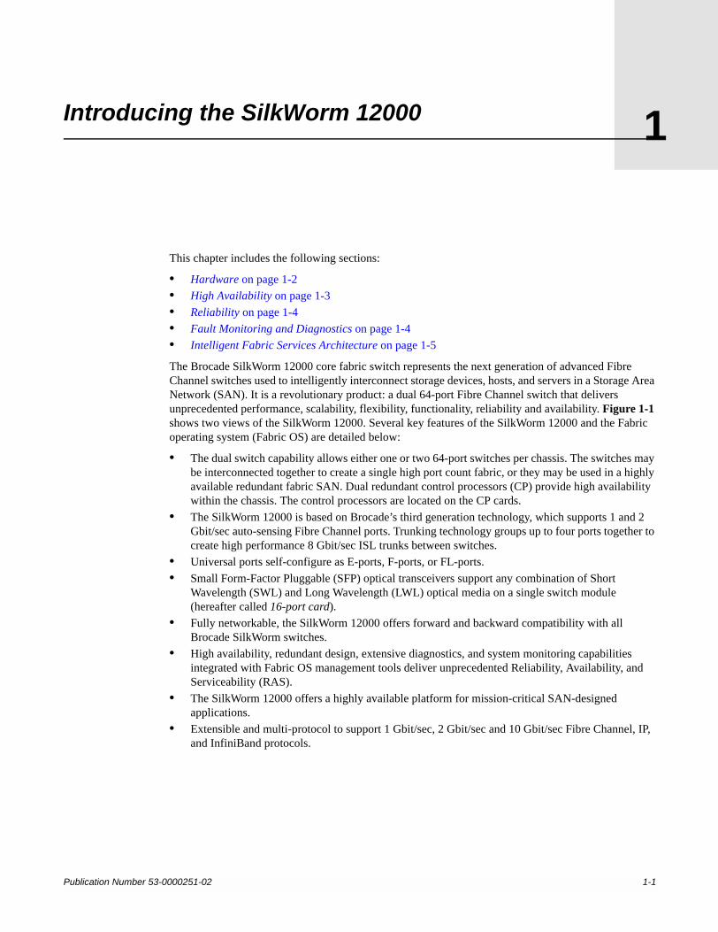
The Brocade SilkWorm 12000 core fabric switch represents the next generation of advanced Fibre Channel switches used to intelligently interconnect storage devices, hosts, and servers in a Storage Area Network (SAN). It is a revolutionary product: a dual 64-port Fibre Channel switch that delivers unprecedented performance, scalability, flexibility, functionality, reliability and availability. Figure 1-1 shows two views of the SilkWorm 12000. Several key features of the SilkWorm 12000 and the Fabric operating system (Fabric OS) are detailed below:
• The dual switch capability allows either one or two 64-port switches per chassis. The switches may be interconnected together to create a single high port count fabric, or they may be used in a highly available redundant fabric SAN. Dual redundant control processors (CP) provide high availability within the chassis. The control processors are located on the CP cards.
• The SilkWorm 12000 is based on Brocade’s third generation technology, which supports 1 and 2 Gbit/sec auto-sensing Fibre Channel ports. Trunking technology groups up to four ports together to create high performance 8 Gbit/sec ISL trunks between switches.
• Universal ports self-configure as E-ports, F-ports, or FL-ports.• Small Form-Factor Pluggable (SFP) optical transceivers support any combination of Short
Wavelength (SWL) and Long Wavelength (LWL) optical media on a single switch module (hereafter called 16-port card).
• Fully networkable, the SilkWorm 12000 offers forward and backward compatibility with all Brocade SilkWorm switches.
• High availability, redundant design, extensive diagnostics, and system monitoring capabilities integrated with Fabric OS management tools deliver unprecedented Reliability, Availability, and Serviceability (RAS).
• The SilkWorm 12000 offers a highly available platform for mission-critical SAN-designed applications.
• Extensible and multi-protocol to support 1 Gbit/sec, 2 Gbit/sec and 10 Gbit/sec Fibre Channel, IP, and InfiniBand protocols.
1-1
Introducing the SilkWorm 120001
Figure 1-1 Cable and non-cable side views of the SilkWorm 12000
HardwareThe SilkWorm 12000 features a modular and scalable mechanical construction that allows a wide range of flexibility in switch installation, Fabric design, and maintenance. Using a 14U (rack unit) mechanical design, up to three SilkWorm 12000 chassis may be mounted in a standard 42U rack, supporting as many as 384 Fibre Channel ports in a single rack. As shown in Figure 1-2, the modular multi-card assembly chassis of the SilkWorm 12000 consists of the following:
• Up to eight hot-swappable 16-port cards, delivering up to two separate 64-port Fibre Channel switches in a single chassis. Each 64-port switch uses four 16-port cards.
• Two slots for Control Processor cards.- A single active CP card can control both 64-port switches in the chassis.- A redundant CP card can assume control of a single or dual switch configuration in the event of
an active CP failure.• Modular hot-swappable Field Replaceable Units (FRUs):
- 16-Port Card - Control Processor Card (CP Card)- Small Form-Factor Pluggable (SFP) optical transceivers- Blower assembly- Power supply
Figure 1-2 identifies the components as described above.
Cable Side (Front) Non-Cable Side (Rear)
1-2 Publication Number 53-0000251-02
Introducing the SilkWorm 12000 1
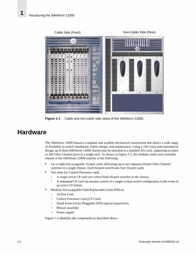
Figure 1-2 SilkWorm 12000 With Identified Components
High AvailabilityHigh availability is an all-encompassing term, and this term normally includes attributes such as reliability and availability. If a system is under continuous operation, it is accessible 7 days a week and 24 hours per day by users and the system manager. Availability is designated in terms of 9s. For example, the architecture of the SilkWorm 12000 is designed for availability in excess of 99.999%.
The following features contribute to the high availability design of the SilkWorm 12000:
• Redundant, hot-swappable components• Redundant power and cooling subsystems• No single point of failure• Enhanced data integrity on all data paths• Fabric Shortest Path First (FSPF) automatic rerouting around failed links• Integration with SNMP managers• Automatic Control Processor fail over
Port 15
Port 0
Slot 1
16-port cards
1-4 Slot numbers
7-10
Power supply #4
Power supply #3
Power supply #2
Power supply #1
Slot 10
2 CP cardsSlot numbers 5 and 6
Publication Number 53-0000251-02 1-3
Introducing the SilkWorm 120001
The SilkWorm 12000 high availability software architecture provides a common framework for all applications that reside on the system and allows global and local states to be maintained such that any component failure is fully manageable. High availability elements consist of the High Availability Manager, the heartbeat, the fault/health framework, the replicated database, initialization, and software upgrade. The software high availability model is discussed in more detail later in this section.
The power supplies (four total) support two 64-port switches in a chassis with the ability to tolerate the failure of as many as two power supplies. The power supplies are hot-swappable, without taking the switch down and without incurring any outage.
The blower assemblies (three total) are also hot-swappable and the chassis can operate fully with only two blower assemblies in place allowing for the failed blower assembly to be replaced with no outage.
The recommended systems networks for high availability include the use of redundant fabrics and dual paths from hosts to storage devices in a SAN. When dual fabrics are used, one switch, one link, or an entire fabric can go down, but data traffic will be re-routed to the alternate path ensuring that the SAN remains operational.
ReliabilityIn addition to being available, the system must be reliable. This means that some, if not all, of its internal state must be maintained. In a reliable system, a user is not aware of the internal state of the chassis components and will experience continued system service with zero degradation of service.
The SilkWorm 12000 provides the following features to ensure reliability. All data inside the switch is protected by the following Error Detection and Correction mechanisms as follows:
• Power-on self test (POST)• Error detection and fault isolation (EDFI), such as cyclic redundancy checking (CRC), parity
checking, checksum, and illegal address checking• Dual control processors, with each control processor containing two serial ports and one Ethernet
port. Offline Control Processor diagnostics and remote diagnostics make troubleshooting straightforward.
• I2C monitoring and control of environmental conditions
Fault Monitoring and DiagnosticsFault monitoring, diagnostic tests, and system status indicators simplify management and ensure availability of the SilkWorm 12000.
Diagnostic testing occurs in three areas: Power-On Self Test (POST), switch level testing, and manufacturing tests. The Power-On Self Test is card oriented and ensures that the switch is ready for use during power up. Switch level testing is done at the user port level. These tests rely on the standard Fabric OS support to provide routing and port setup. Manufacturing support includes long duration testing.
The WWN card located on the non-cable side of the switch summarizes the system status of each 16-port card, each Control Processor Card, and each power supply module. LEDs on the blowers show the status of the blower assemblies.
1-4 Publication Number 53-0000251-02
Introducing the SilkWorm 12000 1
Brocade’s Fabric Watch exposes enhanced status reporting capabilities of the SilkWorm switches through all the standard management interfaces, including SNMP, the Fabric Access Layer API, Brocade Web Tools, Fabric Manager, and the command line interface.
Intelligent Fabric Services ArchitectureFabric OS v4.0 (required for the SilkWorm 12000) provides a wide variety of Advanced Fabric Services that are designed to improve the investment protection, security, performance, scalability, and efficiency of Brocade SAN fabrics.
Features of Fabric OS v4.0 include Trunking, Advanced Zoning, and Advanced Performance Monitoring. These features, some of which are also available in previous versions of Fabric OS, are discussed in the following pages.
Advanced Performance MonitoringAdvanced Performance Monitoring (available on 2 Gbit/sec switches) can monitor performance characteristics on any attribute within the first 64 bytes of a Fibre Channel frame. Predefined graphs measure end-to-end performance; port, switch, and AL-PA bandwidth utilization; SCSI commands (read, write, and read/write); and protocol comparisons (SCSI versus IP). As a result, performance monitoring provides the foundation for performance tuning, resource optimization, service level agreement compliance reporting, and bill-back applications.
Advanced ZoningAdvanced Zoning software limits access to data by segmenting a fabric into virtual private SANs. On1 Gbit/sec and 2 Gbit/sec switches, software-enforced zoning prevents hosts from discovering unauthorized target devices. Hardware-enforced zoning prevents a host from accessing a device that is unauthorized. This provides the most secure zoning available. In addition, Advanced Zoning on2 Gbit/sec switches enables hardware enforcement for devices identified by World Wide Name (WWN). This is new functionality that was not available in the SilkWorm 2000 series switches, which could only do soft WWN zoning. With WWN zoning, zone enforcement adjusts automatically, even if a device moves to another port. This new zoning model allows for the continued flexibility that traditional software-enhanced zoning provides plus garners the security benefits of legacy hardware-enforced zoning.
Extended FabricsExtended Fabrics software enables long distance (100km) ISLs over dark fiber or Dense Wave Division Multiplexing (DWDM) connections at full bandwidth.
Publication Number 53-0000251-02 1-5

Introducing the SilkWorm 120001
Fabric WatchFabric Watch software enables organizations to set thresholds and ranges for SAN fabrics, and raise management alerts when performance or errors vary outside predefined ranges.
ISL TrunkingISL Trunking increases the performance and availability of links between 2 Gbit/sec switches and minimizes the SAN management effort. Up to four 2 Gbit/sec ISLs between two switches can be combined into a single trunk, or logical ISL, at 8 Gbit/sec. Traffic is load balanced across all the links (i.e. any traffic can go across any available trunk link). This is an improvement over current static routing and load sharing where servers are allocated individual dedicated links.
QuickLoop/Fabric Assist (QLFA)QuickLoop/Fabric Assist (QLFA) connects private loop hosts to the SAN fabric for better performance and fault management, while protecting investments in legacy loop devices. Because many legacy devices are designed for FC-AL configurations, Fabric OS translative mode protects investments by supporting private loop target devices. The SilkWorm 12000 running Fabric OS v4.0 supports translative mode. Therefore switches that do support QuickLoop or Fabric Assist can be connected to a SilkWorm 12000, even though the SilkWorm 12000 does not support QuickLoop or Fabric Assist directly. It is possible to connect devices that are accessed by QuickLoop/Fabric Assist devices to the SilkWorm 12000. This means that any type of target device may be attached to a switch running Fabric OS v4.0 and may be included in a QuickLoop Fabric Assist zone that has its private host attached to a switch running QuickLoop and Zoning. QuickLoop and Zoning are pre-requisites for QLFA, on Fabric OS v2.3 or later (SilkWorm 2xxx) or v3.0.1 or later (SilkWorm 3800/3200).
1-6 Publication Number 53-0000251-02
Publication Number 53-0000251-02
2
SilkWorm 12000 Architecture and What Is NewThis chapter includes the following sections:
• Fabric OS 4.0 on page 2-1• Dual Switch Model on page 2-2• Port Addressing and Area Numbering on page 2-5• Compatibility on page 2-10• Software High Availability Model on page 2-11
Note: All topics in this section establish a foundation for further discussions regarding the design, operation, and management of the SilkWorm 12000 and SilkWorm 12000 based SANs. Where appropriate, detail is provided in this section to identify key changes between the SilkWorm 12000 and previous SilkWorm switch models or to highlight key architectural features.
The SilkWorm 12000 utilizes embedded Linux as its underlying operating system, however all SAN management is still performed on the Fabric OS level. While the impact to previous users of SilkWorm switches is nominal, it is important to note what has changed, and what prompted these changes. The dual switch model introduces several new concepts that are important to understand for the design, deployment, and maintenance of the SilkWorm 12000 and SilkWorm 12000-based SANs. The 16-port card design of the SilkWorm 12000 introduces a new “slot” operand to many commands, and a new model for port identification that should be understood for effective operation of the SilkWorm 12000. The SilkWorm 12000 is compatible with all Brocade switch models and is interoperable with switches from vendors such as McData. To enable this compatibility, you must change certain configuration settings before connecting other switches to the SilkWorm 12000. Finally, the software high availability architecture is discussed.
Fabric OS 4.0Fabric OS v4.0 is built upon a real-time version of Linux version 2.4. Linux was chosen due to industry wide support for hardware and software, portability, and scalability. Figure 2-1 shows the screen output when booting the switch. Notice the references to Linux.
2-1
SilkWorm 12000 Architecture and What Is New2
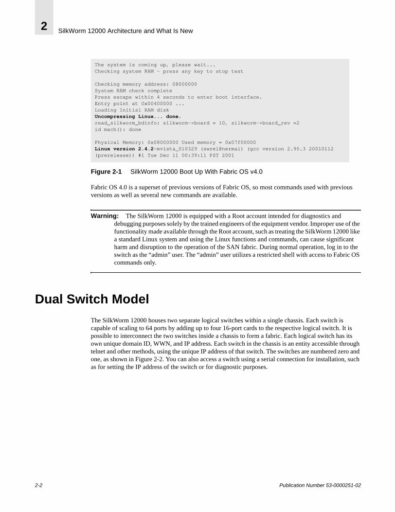
Figure 2-1 SilkWorm 12000 Boot Up With Fabric OS v4.0
Fabric OS 4.0 is a superset of previous versions of Fabric OS, so most commands used with previous versions as well as several new commands are available.
Warning: The SilkWorm 12000 is equipped with a Root account intended for diagnostics and debugging purposes solely by the trained engineers of the equipment vendor. Improper use of the functionality made available through the Root account, such as treating the SilkWorm 12000 like a standard Linux system and using the Linux functions and commands, can cause significant harm and disruption to the operation of the SAN fabric. During normal operation, log in to the switch as the “admin” user. The “admin” user utilizes a restricted shell with access to Fabric OS commands only.
Dual Switch ModelThe SilkWorm 12000 houses two separate logical switches within a single chassis. Each switch is capable of scaling to 64 ports by adding up to four 16-port cards to the respective logical switch. It is possible to interconnect the two switches inside a chassis to form a fabric. Each logical switch has its own unique domain ID, WWN, and IP address. Each switch in the chassis is an entity accessible through telnet and other methods, using the unique IP address of that switch. The switches are numbered zero and one, as shown in Figure 2-2. You can also access a switch using a serial connection for installation, such as for setting the IP address of the switch or for diagnostic purposes.
The system is coming up, please wait...Checking system RAM - press any key to stop test
Checking memory address: 08000000System RAM check completePress escape within 4 seconds to enter boot interface.Entry point at 0x00400000 ...Loading Initial RAM diskUncompressing Linux... done.read_silkworm_bdinfo: silkworm->board = 10, silkworm->board_rev =2id mach(): done
Physical Memory: 0x08000000 Used memory = 0x07f00000Linux version 2.4.2-mvista_010329 (swrel@nermal) (gcc version 2.95.3 20010112 (prerelease)) #1 Tue Dec 11 00:39:11 PST 2001
2-2 Publication Number 53-0000251-02
SilkWorm 12000 Architecture and What Is New 2
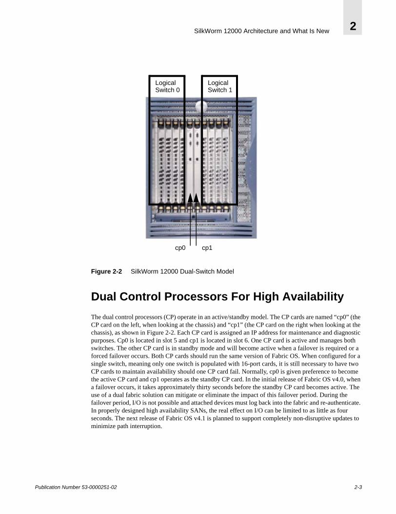
Figure 2-2 SilkWorm 12000 Dual-Switch Model
Dual Control Processors For High AvailabilityThe dual control processors (CP) operate in an active/standby model. The CP cards are named “cp0” (the CP card on the left, when looking at the chassis) and “cp1” (the CP card on the right when looking at the chassis), as shown in Figure 2-2. Each CP card is assigned an IP address for maintenance and diagnostic purposes. Cp0 is located in slot 5 and cp1 is located in slot 6. One CP card is active and manages both switches. The other CP card is in standby mode and will become active when a failover is required or a forced failover occurs. Both CP cards should run the same version of Fabric OS. When configured for a single switch, meaning only one switch is populated with 16-port cards, it is still necessary to have two CP cards to maintain availability should one CP card fail. Normally, cp0 is given preference to become the active CP card and cp1 operates as the standby CP card. In the initial release of Fabric OS v4.0, when a failover occurs, it takes approximately thirty seconds before the standby CP card becomes active. The use of a dual fabric solution can mitigate or eliminate the impact of this failover period. During the failover period, I/O is not possible and attached devices must log back into the fabric and re-authenticate. In properly designed high availability SANs, the real effect on I/O can be limited to as little as four seconds. The next release of Fabric OS v4.1 is planned to support completely non-disruptive updates to minimize path interruption.
Logical Switch 0
Logical Switch 1
cp0 cp1
Publication Number 53-0000251-02 2-3
SilkWorm 12000 Architecture and What Is New2
The dual CP card model and the concept of logical switches is a change from past SilkWorm switch implementations. The SilkWorm 2000 and 3000 families of 8-port and 16-port switches all had a static relationship between the processor and the switch. Now the switch and the processor are de-coupled. One implication of this model is that instead of downloading firmware to a switch, it is necessary to download firmware to a CP card.
Note: The time it takes to activate the standby CP, when a failover occurs, will be considerably less when using Fabric OS 4.1 and greater.
Accessing the SilkWorm 12000 SwitchesWhen accessing SilkWorm 12000 switches, it is possible to access either switch by its respective IP address or by using a serial connection to the active CP card. It is possible to access a CP card by telnet using the respective CP card’s IP address or by connecting a serial cable to the CP card. Access to the CP card should be limited to: installation purposes, setting a switch’s IP address, doing firmware maintenance (i.e., downloads), or for diagnostic purposes.
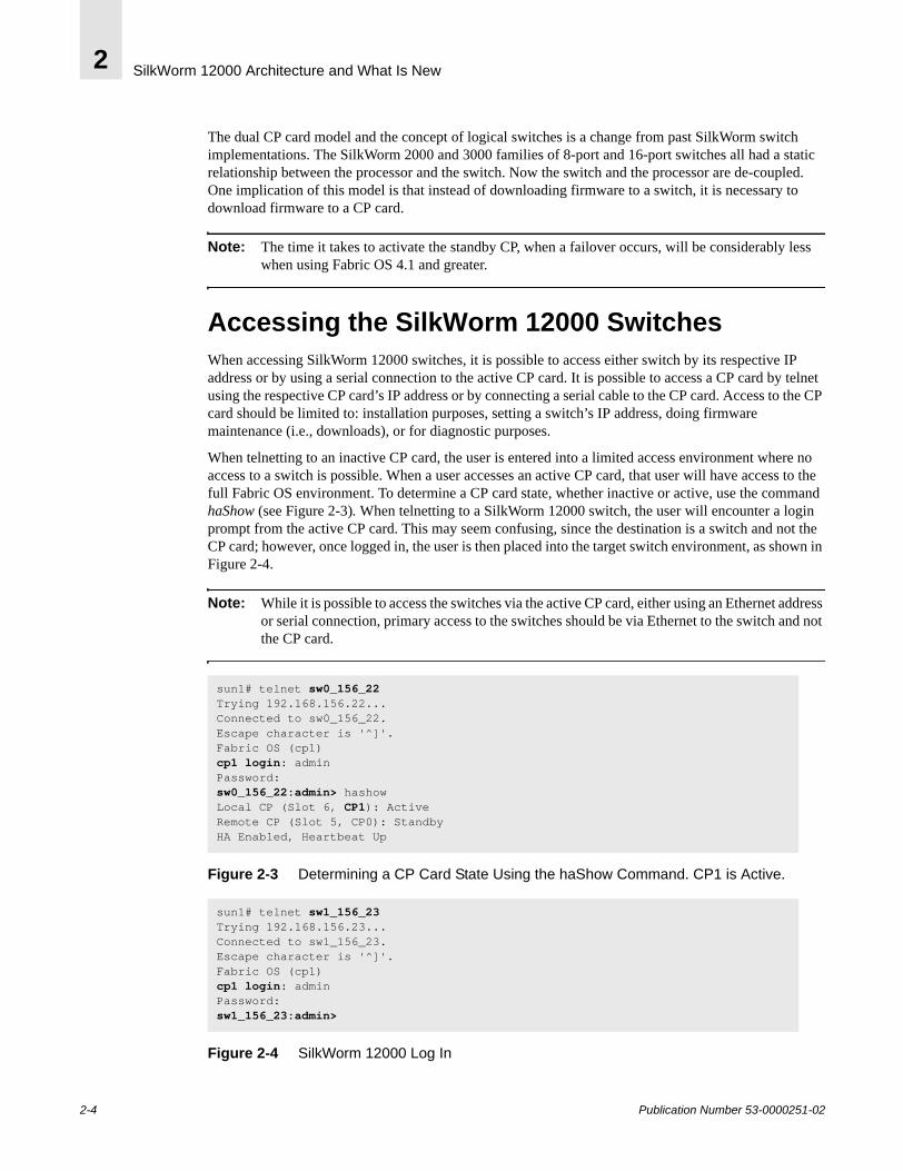
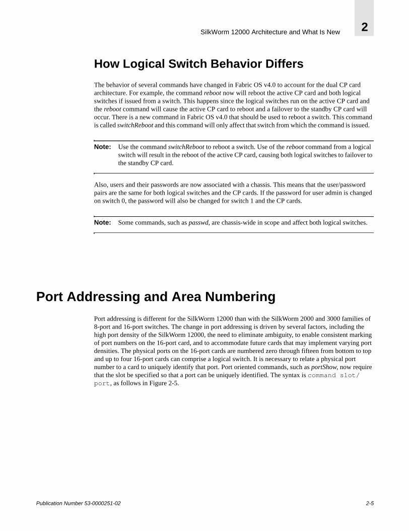
When telnetting to an inactive CP card, the user is entered into a limited access environment where no access to a switch is possible. When a user accesses an active CP card, that user will have access to the full Fabric OS environment. To determine a CP card state, whether inactive or active, use the command haShow (see Figure 2-3). When telnetting to a SilkWorm 12000 switch, the user will encounter a login prompt from the active CP card. This may seem confusing, since the destination is a switch and not the CP card; however, once logged in, the user is then placed into the target switch environment, as shown in Figure 2-4.
Note: While it is possible to access the switches via the active CP card, either using an Ethernet address or serial connection, primary access to the switches should be via Ethernet to the switch and not the CP card.
Figure 2-3 Determining a CP Card State Using the haShow Command. CP1 is Active.
Figure 2-4 SilkWorm 12000 Log In
sun1# telnet sw0_156_22Trying 192.168.156.22...Connected to sw0_156_22.Escape character is '^]'.Fabric OS (cp1)cp1 login: adminPassword: sw0_156_22:admin> hashowLocal CP (Slot 6, CP1): ActiveRemote CP (Slot 5, CP0): StandbyHA Enabled, Heartbeat Up
sun1# telnet sw1_156_23Trying 192.168.156.23...Connected to sw1_156_23.Escape character is '^]'.Fabric OS (cp1)cp1 login: adminPassword: sw1_156_23:admin>
2-4 Publication Number 53-0000251-02
SilkWorm 12000 Architecture and What Is New 2
How Logical Switch Behavior DiffersThe behavior of several commands have changed in Fabric OS v4.0 to account for the dual CP card architecture. For example, the command reboot now will reboot the active CP card and both logical switches if issued from a switch. This happens since the logical switches run on the active CP card and the reboot command will cause the active CP card to reboot and a failover to the standby CP card will occur. There is a new command in Fabric OS v4.0 that should be used to reboot a switch. This command is called switchReboot and this command will only affect that switch from which the command is issued.
Note: Use the command switchReboot to reboot a switch. Use of the reboot command from a logical switch will result in the reboot of the active CP card, causing both logical switches to failover to the standby CP card.
Also, users and their passwords are now associated with a chassis. This means that the user/password pairs are the same for both logical switches and the CP cards. If the password for user admin is changed on switch 0, the password will also be changed for switch 1 and the CP cards.
Note: Some commands, such as passwd, are chassis-wide in scope and affect both logical switches.
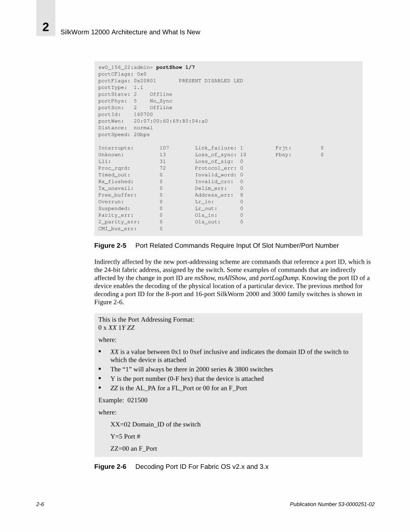
Port Addressing and Area NumberingPort addressing is different for the SilkWorm 12000 than with the SilkWorm 2000 and 3000 families of 8-port and 16-port switches. The change in port addressing is driven by several factors, including the high port density of the SilkWorm 12000, the need to eliminate ambiguity, to enable consistent marking of port numbers on the 16-port card, and to accommodate future cards that may implement varying port densities. The physical ports on the 16-port cards are numbered zero through fifteen from bottom to top and up to four 16-port cards can comprise a logical switch. It is necessary to relate a physical port number to a card to uniquely identify that port. Port oriented commands, such as portShow, now require that the slot be specified so that a port can be uniquely identified. The syntax is command slot/port, as follows in Figure 2-5.
Publication Number 53-0000251-02 2-5
SilkWorm 12000 Architecture and What Is New2
Figure 2-5 Port Related Commands Require Input Of Slot Number/Port Number
Indirectly affected by the new port-addressing scheme are commands that reference a port ID, which is the 24-bit fabric address, assigned by the switch. Some examples of commands that are indirectly affected by the change in port ID are nsShow, nsAllShow, and portLogDump. Knowing the port ID of a device enables the decoding of the physical location of a particular device. The previous method for decoding a port ID for the 8-port and 16-port SilkWorm 2000 and 3000 family switches is shown in Figure 2-6.
Figure 2-6 Decoding Port ID For Fabric OS v2.x and 3.x
sw0_156_22:admin> portShow 1/7portCFlags: 0x0portFlags: 0x20801 PRESENT DISABLED LEDportType: 1.1portState: 2 Offline portPhys: 5 No_Sync portScn: 2 Offline portId: 160700portWwn: 20:07:00:60:69:80:04:a0Distance: normalportSpeed: 2Gbps
Interrupts: 107 Link_failure: 1 Frjt: 0 Unknown: 13 Loss_of_sync: 10 Fbsy: 0 Lli: 31 Loss_of_sig: 0 Proc_rqrd: 72 Protocol_err: 0 Timed_out: 0 Invalid_word: 0 Rx_flushed: 0 Invalid_crc: 0 Tx_unavail: 0 Delim_err: 0 Free_buffer: 0 Address_err: 8 Overrun: 0 Lr_in: 0 Suspended: 0 Lr_out: 0 Parity_err: 0 Ols_in: 0 2_parity_err: 0 Ols_out: 0 CMI_bus_err: 0
This is the Port Addressing Format:0 x XX 1Y ZZ
where:
• XX is a value between 0x1 to 0xef inclusive and indicates the domain ID of the switch to which the device is attached
• The “1” will always be there in 2000 series & 3800 switches• Y is the port number (0-F hex) that the device is attached• ZZ is the AL_PA for a FL_Port or 00 for an F_Port
Example: 021500
where:
XX=02 Domain_ID of the switch
Y=5 Port #
ZZ=00 an F_Port
2-6 Publication Number 53-0000251-02

SilkWorm 12000 Architecture and What Is New 2
The port-addressing scheme for Fabric OS v4.0 is summarized in Figure 2-7.
Figure 2-7 Decoding Port ID For Fabric OS v4.0
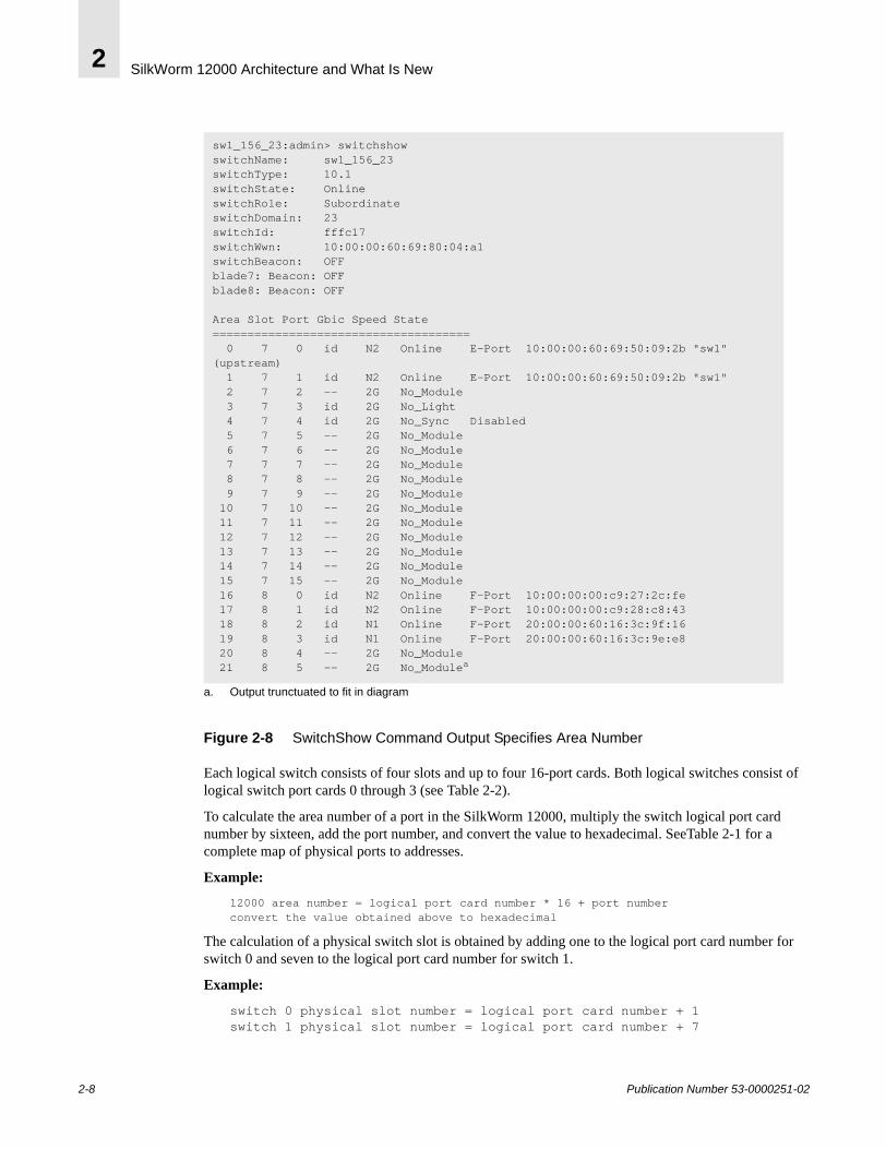
Since the port-addressing scheme has changed for the SilkWorm 12000, so has the decoding for a particular port ID. The concept of area number is new in the SilkWorm 12000. The area number is used in the same way a port number is used for the SilkWorm 2000 series and 3800 switches. When specifying zoning configurations by port number it is necessary to utilize the area number. Also several commands, such as switchShow or nsShow, specify area number in the output (see Figure 2-8).
This is the Port Addressing Format:0 x WW XY ZZ
where:
• WW is a value between 0x1 to 0xef inclusive and indicates the domain id of the switch to which the device is attached
• X is the logical port card number• Y is the port number (0-F hex) that the device is attached• ZZ is the AL_PA for a FL_Port (Loop) or 00 for an F_Port
Example 1: 170f00
where:
WW =23 Domain_ID of the switch
X= logical port card 0
Y= port number 15 (0xf)
ZZ=00 an F_Port.
Example 2: 162ed2
where:
WW =22 Domain_ID of the switch
X= logical port card 2
Y= port number 14 (0xe)
ZZ=d2 ALPA (FL_Port)
Publication Number 53-0000251-02 2-7
SilkWorm 12000 Architecture and What Is New2
Figure 2-8 SwitchShow Command Output Specifies Area Number
Each logical switch consists of four slots and up to four 16-port cards. Both logical switches consist of logical switch port cards 0 through 3 (see Table 2-2).
To calculate the area number of a port in the SilkWorm 12000, multiply the switch logical port card number by sixteen, add the port number, and convert the value to hexadecimal. SeeTable 2-1 for a complete map of physical ports to addresses.
Example:
12000 area number = logical port card number * 16 + port numberconvert the value obtained above to hexadecimal
The calculation of a physical switch slot is obtained by adding one to the logical port card number for switch 0 and seven to the logical port card number for switch 1.
Example:
switch 0 physical slot number = logical port card number + 1switch 1 physical slot number = logical port card number + 7
sw1_156_23:admin> switchshowswitchName: sw1_156_23switchType: 10.1switchState: Online switchRole: SubordinateswitchDomain: 23switchId: fffc17switchWwn: 10:00:00:60:69:80:04:a1switchBeacon: OFFblade7: Beacon: OFFblade8: Beacon: OFF
Area Slot Port Gbic Speed State ===================================== 0 7 0 id N2 Online E-Port 10:00:00:60:69:50:09:2b "sw1" (upstream) 1 7 1 id N2 Online E-Port 10:00:00:60:69:50:09:2b "sw1" 2 7 2 -- 2G No_Module 3 7 3 id 2G No_Light 4 7 4 id 2G No_Sync Disabled 5 7 5 -- 2G No_Module 6 7 6 -- 2G No_Module 7 7 7 -- 2G No_Module 8 7 8 -- 2G No_Module 9 7 9 -- 2G No_Module 10 7 10 -- 2G No_Module 11 7 11 -- 2G No_Module 12 7 12 -- 2G No_Module 13 7 13 -- 2G No_Module 14 7 14 -- 2G No_Module 15 7 15 -- 2G No_Module 16 8 0 id N2 Online F-Port 10:00:00:00:c9:27:2c:fe 17 8 1 id N2 Online F-Port 10:00:00:00:c9:28:c8:43 18 8 2 id N1 Online F-Port 20:00:00:60:16:3c:9f:16 19 8 3 id N1 Online F-Port 20:00:00:60:16:3c:9e:e8 20 8 4 -- 2G No_Module 21 8 5 -- 2G No_Modulea
a. Output trunctuated to fit in diagram
2-8 Publication Number 53-0000251-02
SilkWorm 12000 Architecture and What Is New 2
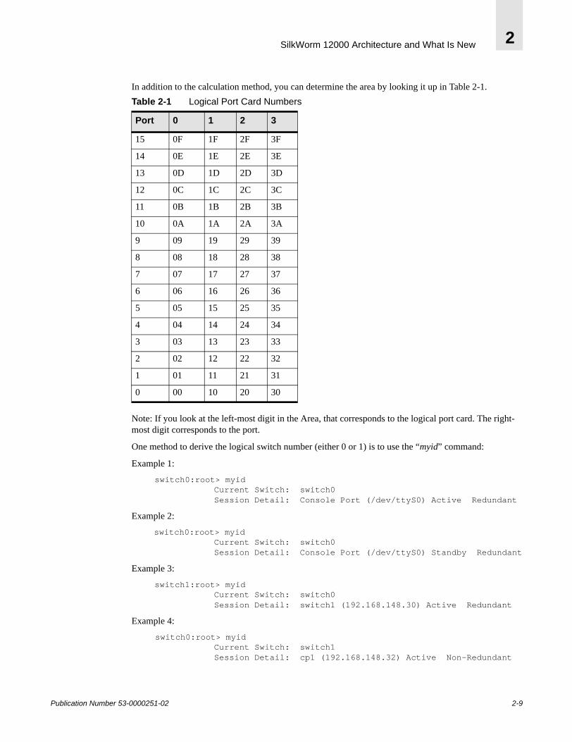
In addition to the calculation method, you can determine the area by looking it up in Table 2-1.
Note: If you look at the left-most digit in the Area, that corresponds to the logical port card. The right-most digit corresponds to the port.
One method to derive the logical switch number (either 0 or 1) is to use the “myid” command:
Example 1:
switch0:root> myid Current Switch: switch0 Session Detail: Console Port (/dev/ttyS0) Active Redundant
Example 2:
switch0:root> myid Current Switch: switch0 Session Detail: Console Port (/dev/ttyS0) Standby Redundant
Example 3:
switch1:root> myid Current Switch: switch0 Session Detail: switch1 (192.168.148.30) Active Redundant
Example 4:
switch0:root> myid Current Switch: switch1 Session Detail: cp1 (192.168.148.32) Active Non-Redundant
Table 2-1 Logical Port Card Numbers
Port 0 1 2 3
15 0F 1F 2F 3F
14 0E 1E 2E 3E
13 0D 1D 2D 3D
12 0C 1C 2C 3C
11 0B 1B 2B 3B
10 0A 1A 2A 3A
9 09 19 29 39
8 08 18 28 38
7 07 17 27 37
6 06 16 26 36
5 05 15 25 35
4 04 14 24 34
3 03 13 23 33
2 02 12 22 32
1 01 11 21 31
0 00 10 20 30
Publication Number 53-0000251-02 2-9
SilkWorm 12000 Architecture and What Is New2
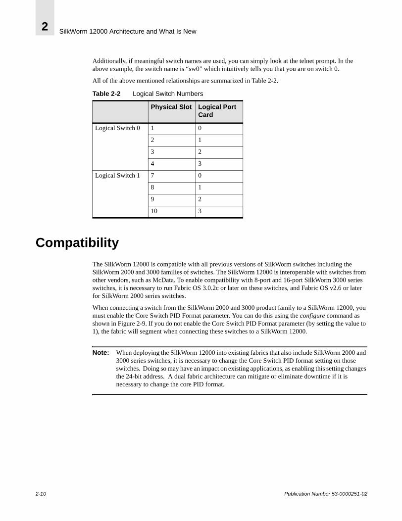
Additionally, if meaningful switch names are used, you can simply look at the telnet prompt. In the above example, the switch name is “sw0” which intuitively tells you that you are on switch 0.
All of the above mentioned relationships are summarized in Table 2-2.
CompatibilityThe SilkWorm 12000 is compatible with all previous versions of SilkWorm switches including the SilkWorm 2000 and 3000 families of switches. The SilkWorm 12000 is interoperable with switches from other vendors, such as McData. To enable compatibility with 8-port and 16-port SilkWorm 3000 series switches, it is necessary to run Fabric OS 3.0.2c or later on these switches, and Fabric OS v2.6 or later for SilkWorm 2000 series switches.
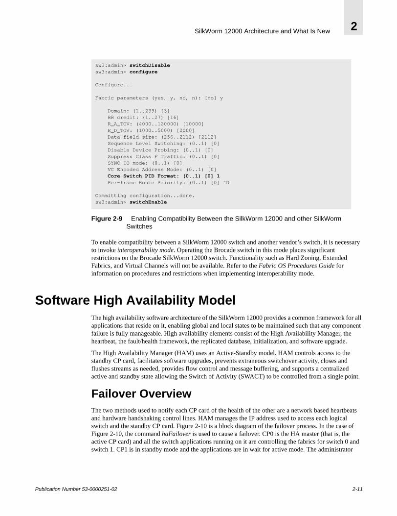
When connecting a switch from the SilkWorm 2000 and 3000 product family to a SilkWorm 12000, you must enable the Core Switch PID Format parameter. You can do this using the configure command as shown in Figure 2-9. If you do not enable the Core Switch PID Format parameter (by setting the value to 1), the fabric will segment when connecting these switches to a SilkWorm 12000.
Note: When deploying the SilkWorm 12000 into existing fabrics that also include SilkWorm 2000 and 3000 series switches, it is necessary to change the Core Switch PID format setting on those switches. Doing so may have an impact on existing applications, as enabling this setting changes the 24-bit address. A dual fabric architecture can mitigate or eliminate downtime if it is necessary to change the core PID format.
Table 2-2 Logical Switch Numbers
Physical Slot Logical Port Card
Logical Switch 0 1 0
2 1
3 2
4 3
Logical Switch 1 7 0
8 1
9 2
10 3
2-10 Publication Number 53-0000251-02
SilkWorm 12000 Architecture and What Is New 2
Figure 2-9 Enabling Compatibility Between the SilkWorm 12000 and other SilkWorm Switches
To enable compatibility between a SilkWorm 12000 switch and another vendor’s switch, it is necessary to invoke interoperability mode. Operating the Brocade switch in this mode places significant restrictions on the Brocade SilkWorm 12000 switch. Functionality such as Hard Zoning, Extended Fabrics, and Virtual Channels will not be available. Refer to the Fabric OS Procedures Guide for information on procedures and restrictions when implementing interoperability mode.
Software High Availability ModelThe high availability software architecture of the SilkWorm 12000 provides a common framework for all applications that reside on it, enabling global and local states to be maintained such that any component failure is fully manageable. High availability elements consist of the High Availability Manager, the heartbeat, the fault/health framework, the replicated database, initialization, and software upgrade.
The High Availability Manager (HAM) uses an Active-Standby model. HAM controls access to the standby CP card, facilitates software upgrades, prevents extraneous switchover activity, closes and flushes streams as needed, provides flow control and message buffering, and supports a centralized active and standby state allowing the Switch of Activity (SWACT) to be controlled from a single point.
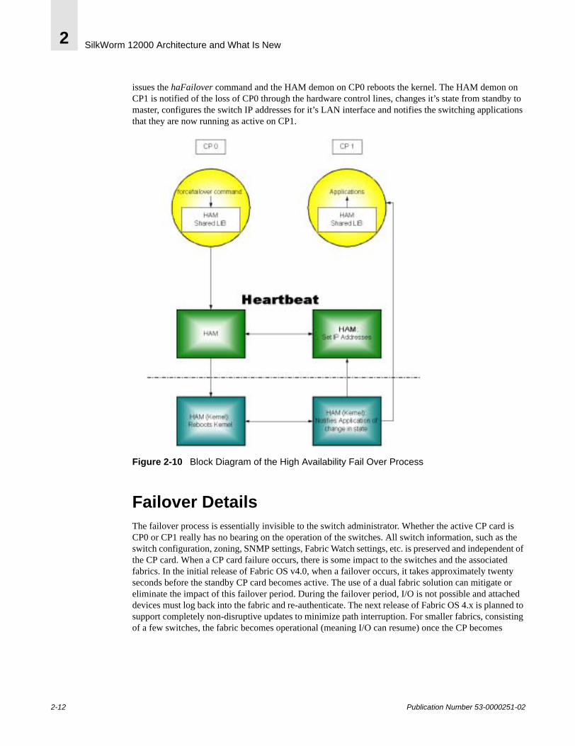
Failover OverviewThe two methods used to notify each CP card of the health of the other are a network based heartbeats and hardware handshaking control lines. HAM manages the IP address used to access each logical switch and the standby CP card. Figure 2-10 is a block diagram of the failover process. In the case of Figure 2-10, the command haFailover is used to cause a failover. CP0 is the HA master (that is, the active CP card) and all the switch applications running on it are controlling the fabrics for switch 0 and switch 1. CP1 is in standby mode and the applications are in wait for active mode. The administrator
sw3:admin> switchDisablesw3:admin> configure
Configure...
Fabric parameters (yes, y, no, n): [no] y
Domain: (1..239) [3] BB credit: (1..27) [16] R_A_TOV: (4000..120000) [10000] E_D_TOV: (1000..5000) [2000] Data field size: (256..2112) [2112] Sequence Level Switching: (0..1) [0] Disable Device Probing: (0..1) [0] Suppress Class F Traffic: (0..1) [0] SYNC IO mode: (0..1) [0] VC Encoded Address Mode: (0..1) [0] Core Switch PID Format: (0..1) [0] 1 Per-frame Route Priority: (0..1) [0] ^D
Committing configuration...done.sw3:admin> switchEnable
Publication Number 53-0000251-02 2-11
SilkWorm 12000 Architecture and What Is New2
issues the haFailover command and the HAM demon on CP0 reboots the kernel. The HAM demon on CP1 is notified of the loss of CP0 through the hardware control lines, changes it’s state from standby to master, configures the switch IP addresses for it’s LAN interface and notifies the switching applications that they are now running as active on CP1.
Figure 2-10 Block Diagram of the High Availability Fail Over Process
Failover DetailsThe failover process is essentially invisible to the switch administrator. Whether the active CP card is CP0 or CP1 really has no bearing on the operation of the switches. All switch information, such as the switch configuration, zoning, SNMP settings, Fabric Watch settings, etc. is preserved and independent of the CP card. When a CP card failure occurs, there is some impact to the switches and the associated fabrics. In the initial release of Fabric OS v4.0, when a failover occurs, it takes approximately twenty seconds before the standby CP card becomes active. The use of a dual fabric solution can mitigate or eliminate the impact of this failover period. During the failover period, I/O is not possible and attached devices must log back into the fabric and re-authenticate. The next release of Fabric OS 4.x is planned to support completely non-disruptive updates to minimize path interruption. For smaller fabrics, consisting of a few switches, the fabric becomes operational (meaning I/O can resume) once the CP becomes
2-12 Publication Number 53-0000251-02

SilkWorm 12000 Architecture and What Is New 2
active. For larger fabrics, it may take longer for the fabric to become operational since the higher number of switches in the fabric necessitates a longer convergence period before the fabric becomes operational. At the time a failover occurs, all devices and ISLs connected to switch 0 and switch 1 lose their link until the failover completes. Also any active telnet sessions to the switches or the CP cards are disconnected.
Note: The time it takes to activate the standby CP, when a failover occurs, will be considerably less when using Fabric OS 4.1 and greater.
Publication Number 53-0000251-02 2-13

SilkWorm 12000 Architecture and What Is New2
2-14 Publication Number 53-0000251-02
Publication Number 53-0000251-02
3
SilkWorm 12000 Based SAN DesignsThis chapter includes the following sections:
• Scalability on page 3-3• Performance on page 3-4• Availability on page 3-8 • SilkWorm 12000 Based Fabric Topologies on page 3-10
This chapter assumes that the reader is familiar with the following concepts:
• Core/edge topology characteristics• Locality• Multi-fabric architectures• Congestion• Over-subscription• Device placement strategies
For detailed information about the concepts listed above, refer to the Brocade SAN Design Guide (part number: 53-0000231) and the book Building SANs with Brocade Fabric Switches by Syngress press (ISBN: 1-928994-30-x).
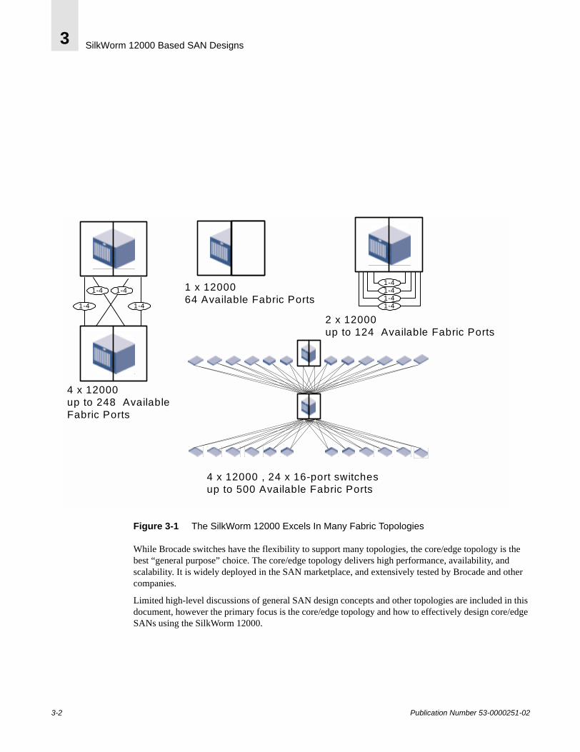
The SilkWorm 12000 is an exceptionally flexible storage-networking switch. Its enhanced network features, high port density, high availability, and broad compatibility allow this switch to fill many different roles. It can be used to form a single-switch 64-port fabric, a two-switch fabric of up to 124 ports, a member of a full mesh, or the core or edge of a highly scalable core/edge fabric. The SilkWorm 12000 is also backwards compatible with the SilkWorm 2000 and 3000 series switches to protect customer investment. Figure 3-1 illustrates these topologies.
3-1
SilkWorm 12000 Based SAN Designs3
1 x 1200064 Available Fabric Ports
2 x 12000up to 124 Available Fabric Ports
4 x 12000up to 248 AvailableFabric Ports
4 x 12000 , 24 x 16-port switchesup to 500 Available Fabric Ports
1-41-41-41-41-41-4
1-41-4
Figure 3-1 The SilkWorm 12000 Excels In Many Fabric Topologies
While Brocade switches have the flexibility to support many topologies, the core/edge topology is the best “general purpose” choice. The core/edge topology delivers high performance, availability, and scalability. It is widely deployed in the SAN marketplace, and extensively tested by Brocade and other companies.
Limited high-level discussions of general SAN design concepts and other topologies are included in this document, however the primary focus is the core/edge topology and how to effectively design core/edge SANs using the SilkWorm 12000.
3-2 Publication Number 53-0000251-02
SilkWorm 12000 Based SAN Designs 3
ScalabilityA key question in the initial design stage of any SAN is the need for scalability. With fabrics built from 16-port switches, the core/edge topology is the dominant choice. It is possible to scale a core/edge fabric from 16 ports to 224 ports using the same architecture without downtime. While other topologies are possible, the scaling of these topologies is limited and disruptive with 16-port switches.
With the SilkWorm 12000, topologies such as the full and partial meshes are more practical since it is possible to scale these topologies beyond 200 ports. This is because the SilkWorm 12000 has a much higher port density. Additionally, trunking capabilities optimize the performance between switches, making the full and partial mesh topologies more efficient.
If the network will expand to beyond a few hundred ports, the core/edge is the topology of choice. Even with the SilkWorm 12000, topologies such as the full mesh are difficult to scale past a few hundred ports non-disruptively or without significant re-cabling. If you use a large port-count switch at the core of your fabric, you greatly increase that fabric’s scalability.
Scaling requirements can also dictate device placement strategies. For example, an initial deployment of a core/edge fabric may leave ports free on the core switches. Placing nodes on these ports can allow full utilization of the fabric. However, each core port can only be used as a node connection point or an ISL connection point. When an ISL connection point is utilized for a SAN device, potentially dozens of nodes of scalability are given up. A very large fabric that needs to scale past several hundred ports should not have nodes directly connected to the core as these devices would have to be later moved to facilitate growth. If the scaling requirements are below a few hundred ports or it is accpetable to re-cable devices, then attaching devices to the core is aviable option.
The cores of a pre-existing core/edge fabric built with 16-port switches can easily be upgraded to SilkWorm 12000 cores. This allows investment protection and scalability without downtime. The preservation of the investment in existing switches is a hallmark of Brocade’s backward compatibility strategy.
In addition to investment protection, per-port cost economics plays a role in the SAN design process. It is now possible to build multi-hundred port SANs using only 16-port switches, only 64-port switches, or a mixture of both. Each approach has benefits: some may prefer a distributed network approach that leverages lower cost 16-port switches, as others may prefer smaller networks of higher port count switches with fewer ISLs. Fiber budgets in campus environments may also impact this decision. As the 16-port switches can be deployed through a data center or campus they may require fewer longer runs between devices and larger central switches. A combination of the smaller and larger port count switches may offer a good design solution.
Note: When considering campus or large data center environments, a combination of smaller and larger port count switches may offer a more practical solution. Since fewer runs between devices and central switches are possible by locating satellite switches with the devices.
The SAN designer has the ability to mix and match switches, leverage backwards compatibility, and preserve investment when creating a SAN design. This allows the SAN to be tailored to the cost and management requirements of the customer.
Publication Number 53-0000251-02 3-3
SilkWorm 12000 Based SAN Designs3
PerformanceThe SilkWorm 12000 delivers many enhanced performance capabilities over previous generation switches. It is possible to dynamically tune a fabric by adding or removing ISLs between SilkWorm switches. With Trunking (SilkWorm 12000, 3800, and 3200), this tuning ability is further enhanced because trunking makes ISL addition transparent to SAN devices and optimizes ISL bandwidth utilization. Current SAN devices are predominantly limited to 1 Gbit/sec, with a rapid migration to2 Gbit/sec in progress. Today’s 1 Gbit/sec devices are rarely able to sustain a 1 Gbit/sec I/O stream. This enables Brocade 1-2 Gbit/sec auto sensing switches to aggregate many 1 Gbit/sec streams across fewer 2 Gbit/sec ISLs. ISL over-subscription is much like the fan-in and fan-out principals used by RAID array vendors: it decreases cost without affecting real-world performance. Trunking, dynamic tuning capabilities, and 1 Gbit/sec to 2 Gbit/sec aggregation combine to create a flexible, powerful, and high performance fabric infrastructure.
ISL Over SubscriptionWhen designing a SAN, it is important to understand performance boundaries of nodes such as storage fan-out ratios and HBA performance limits. While any SAN device that connects to a SAN at 2 Gbit/sec is theoretically capable of 2 Gbit/sec. In reality, that device is most likely to sustain a much lower I/O throughput. If a device truly is capable of generating 2 Gbit/sec of I/O, then the principles of locality should be applied and/or more ISLs should be used.
A very popular SAN application is storage consolidation, in which many hosts share a storage device or port. Several popular storage vendors average a 6:1 host-to-storage fan-out. This means that on average, six hosts are sharing a single storage port. If there were 32 storage ports in a fabric, then one would expect to find an average of 192 hosts. Even if every host requires 1 Gbit/sec or 2 Gbit/sec of bandwidth, the storage devices in the fabric are only capable of delivering 32 Gbit/sec (1 Gbit/sec ports) or 64 Gbit/sec (2 Gbit/sec ports) total throughput. (This implies 3-6 MB/s per host.) While some ports in the fabric may require maximum bandwidth, not all ports could possibly require this simultaneously. In cases where the ratio of host ports to storage ports is not 1:1 (which is the case in most SANs) using too many ISLs merely adds cost. This fan-out ratio is possible as the servers access is random and all servers will not peak at the same time. The worst case performance, however, if all the servers happened to peak for a period of time would be 3-6MB/s.
Note: As a starting point, a 7:1 ISL over-subscription ratio is a reasonable target for a SAN design.
A 7:1 ISL over-subscription ratio is aligned with the de facto storage industry average of 6:1 fan-out. The ISL over-subscription ratio can be adjusted higher or lower to meet particular performance requirements. Note that if the SAN devices connected are 1 Gbit/sec devices and the ISLs are 2 Gbit/sec, the ISL over-subscription ratio decreases by at least half since the lower bandwidth 1 Gbit/sec SAN devices are now aggregated across 2 Gbit/sec ISLs and 4-8 Gbit/sec trunks. This means that a 7:1 ISL over-subscription ratio drops to 3.5:1 and a 3:1 ratio drops to 1.5:1. A lower ISL over subscription ratio means potentially higher bandwidth for the hosts, which may improve performance in some cases.
In designing ISL requirements another consideration allows for fewer ISL consumption is that Trunking does not require dedicated routes for each connected device. It does not suffer from potential imbalances. Without trunking if two standard ISLs are used and there are ten servers they would each support five servers. If five of the servers on one of the ISLs have higher sustained traffic then the other five imbalance may occur where one ISL is over-subscribed where as the other is well under subscribed (i.e.
3-4 Publication Number 53-0000251-02
SilkWorm 12000 Based SAN Designs 3
one is doing 2Gb, the other is only pushing 1G.) With trunking the total bandwidth is utilized between the two trunked ISLs to provide smooth balanced performance up to the full bandwidth of the two lines. Traffic from all ten servers will go across BOTH lines, not one of them, producing even levels of performance. Thus in the example you would see 1.5Gb on each link or more if the 2Gb link was actually limiting performance. This allows administrators to focus only on overall bandwidth requirements rather than the number of devices being routed across ISLs.
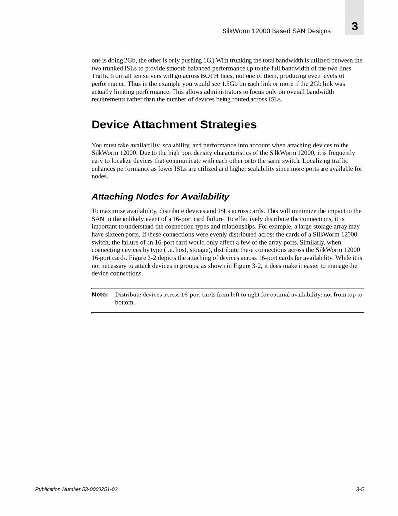
Device Attachment StrategiesYou must take availability, scalability, and performance into account when attaching devices to the SilkWorm 12000. Due to the high port density characteristics of the SilkWorm 12000, it is frequently easy to localize devices that communicate with each other onto the same switch. Localizing traffic enhances performance as fewer ISLs are utilized and higher scalability since more ports are available for nodes.
Attaching Nodes for AvailabilityTo maximize availability, distribute devices and ISLs across cards. This will minimize the impact to the SAN in the unlikely event of a 16-port card failure. To effectively distribute the connections, it is important to understand the connection types and relationships. For example, a large storage array may have sixteen ports. If these connections were evenly distributed across the cards of a SilkWorm 12000 switch, the failure of an 16-port card would only affect a few of the array ports. Similarly, when connecting devices by type (i.e. host, storage), distribute these connections across the SilkWorm 12000 16-port cards. Figure 3-2 depicts the attaching of devices across 16-port cards for availability. While it is not necessary to attach devices in groups, as shown in Figure 3-2, it does make it easier to manage the device connections.
Note: Distribute devices across 16-port cards from left to right for optimal availability; not from top to bottom.
Publication Number 53-0000251-02 3-5
SilkWorm 12000 Based SAN Designs3
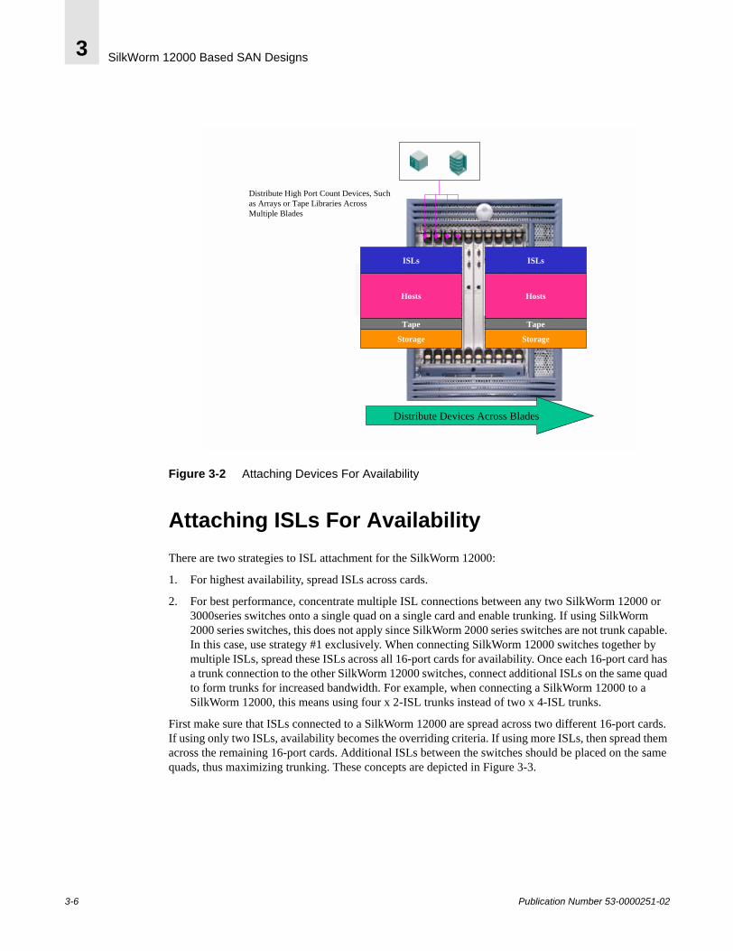
Figure 3-2 Attaching Devices For Availability
Attaching ISLs For AvailabilityThere are two strategies to ISL attachment for the SilkWorm 12000:
1. For highest availability, spread ISLs across cards.
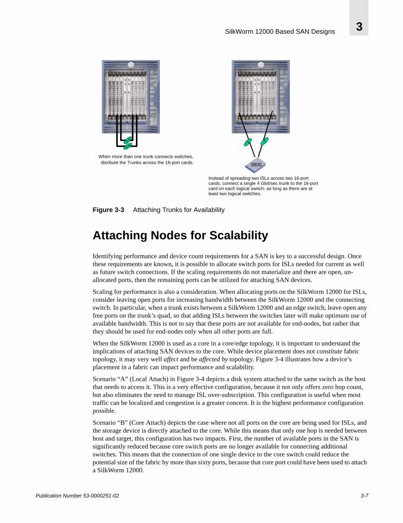
2. For best performance, concentrate multiple ISL connections between any two SilkWorm 12000 or 3000series switches onto a single quad on a single card and enable trunking. If using SilkWorm 2000 series switches, this does not apply since SilkWorm 2000 series switches are not trunk capable. In this case, use strategy #1 exclusively. When connecting SilkWorm 12000 switches together by multiple ISLs, spread these ISLs across all 16-port cards for availability. Once each 16-port card has a trunk connection to the other SilkWorm 12000 switches, connect additional ISLs on the same quad to form trunks for increased bandwidth. For example, when connecting a SilkWorm 12000 to a SilkWorm 12000, this means using four x 2-ISL trunks instead of two x 4-ISL trunks.
First make sure that ISLs connected to a SilkWorm 12000 are spread across two different 16-port cards. If using only two ISLs, availability becomes the overriding criteria. If using more ISLs, then spread them across the remaining 16-port cards. Additional ISLs between the switches should be placed on the same quads, thus maximizing trunking. These concepts are depicted in Figure 3-3.
Distribute High Port Count Devices, Such as Arrays or Tape Libraries Across Multiple Blades
Distribute Devices Across Blades
Storage
Tape
Hosts
ISLs
Storage
Tape
Hosts
ISLs
3-6 Publication Number 53-0000251-02
SilkWorm 12000 Based SAN Designs 3
Figure 3-3 Attaching Trunks for Availability
Attaching Nodes for ScalabilityIdentifying performance and device count requirements for a SAN is key to a successful design. Once these requirements are known, it is possible to allocate switch ports for ISLs needed for current as well as future switch connections. If the scaling requirements do not materialize and there are open, un-allocated ports, then the remaining ports can be utilized for attaching SAN devices.
Scaling for performance is also a consideration. When allocating ports on the SilkWorm 12000 for ISLs, consider leaving open ports for increasing bandwidth between the SilkWorm 12000 and the connecting switch. In particular, when a trunk exists between a SilkWorm 12000 and an edge switch, leave open any free ports on the trunk’s quad, so that adding ISLs between the switches later will make optimum use of available bandwidth. This is not to say that these ports are not available for end-nodes, but rather that they should be used for end-nodes only when all other ports are full.
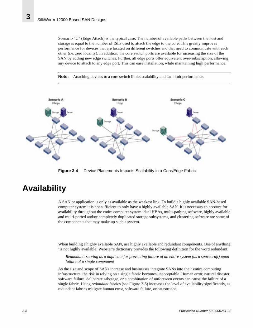
When the SilkWorm 12000 is used as a core in a core/edge topology, it is important to understand the implications of attaching SAN devices to the core. While device placement does not constitute fabric topology, it may very well affect and be affected by topology. Figure 3-4 illustrates how a device’s placement in a fabric can impact performance and scalability.
Scenario “A” (Local Attach) in Figure 3-4 depicts a disk system attached to the same switch as the host that needs to access it. This is a very effective configuration, because it not only offers zero hop count, but also eliminates the need to manage ISL over-subscription. This configuration is useful when most traffic can be localized and congestion is a greater concern. It is the highest performance configuration possible.
Scenario “B” (Core Attach) depicts the case where not all ports on the core are being used for ISLs, and the storage device is directly attached to the core. While this means that only one hop is needed between host and target, this configuration has two impacts. First, the number of available ports in the SAN is significantly reduced because core switch ports are no longer available for connecting additional switches. This means that the connection of one single device to the core switch could reduce the potential size of the fabric by more than sixty ports, because that core port could have been used to attach a SilkWorm 12000.
When more than one trunk connects switches, distribute the Trunks across the 16-port cards. Instead of spreading two ISLs across
two 16-port cards, connect a single 4 Gb/s trunk to the 16-port card on
3800
22-4
2-4
2
When more than one trunk connects switches, disribute the Trunks across the 16-port cards.
Instead of spreading two ISLs across two 16-portcards, connect a single 4 Gbit/sec trunk to the 16-portcard on each logical switch- as long as there are at least two logical switches.
Publication Number 53-0000251-02 3-7
SilkWorm 12000 Based SAN Designs3
Scenario “C” (Edge Attach) is the typical case. The number of available paths between the host and storage is equal to the number of ISLs used to attach the edge to the core. This greatly improves performance for devices that are located on different switches and that need to communicate with each other (i.e. zero locality). In addition, the core switch ports are available for increasing the size of the SAN by adding new edge switches. Further, all edge ports offer equivalent over-subscription, allowing any device to attach to any edge port. This can ease installation, while maintaining high performance.
Note: Attaching devices to a core switch limits scalability and can limit performance.
Figure 3-4 Device Placements Impacts Scalability in a Core/Edge Fabric
AvailabilityA SAN or application is only as available as the weakest link. To build a highly available SAN-based computer system it is not sufficient to only have a highly available SAN. It is necessary to account for availability throughout the entire computer system: dual HBAs, multi-pathing software, highly available and multi-ported and/or completely duplicated storage subsystems, and clustering software are some of the components that may make up such a system.
When building a highly available SAN, use highly available and redundant components. One of anything ‘is not highly available. Webster’s dictionary provides the following definition for the word redundant:
Redundant: serving as a duplicate for preventing failure of an entire system (as a spacecraft) upon failure of a single component
As the size and scope of SANs increase and businesses integrate SANs into their entire computing infrastructure, the risk in relying on a single fabric becomes unacceptable. Human error, natural disaster, software failure, deliberate sabotage, or a combination of unforeseen events can cause the failure of a single fabric. Using redundant fabrics (see Figure 3-5) increases the level of availability significantly, as redundant fabrics mitigate human error, software failure, or catastrophe.
3-8 Publication Number 53-0000251-02
SilkWorm 12000 Based SAN Designs 3
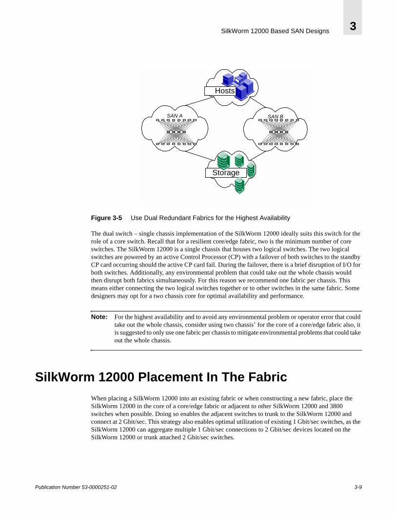
Figure 3-5 Use Dual Redundant Fabrics for the Highest Availability
The dual switch – single chassis implementation of the SilkWorm 12000 ideally suits this switch for the role of a core switch. Recall that for a resilient core/edge fabric, two is the minimum number of core switches. The SilkWorm 12000 is a single chassis that houses two logical switches. The two logical switches are powered by an active Control Processor (CP) with a failover of both switches to the standby CP card occurring should the active CP card fail. During the failover, there is a brief disruption of I/O for both switches. Additionally, any environmental problem that could take out the whole chassis would then disrupt both fabrics simultaneously. For this reason we recommend one fabric per chassis. This means either connecting the two logical switches together or to other switches in the same fabric. Some designers may opt for a two chassis core for optimal availability and performance.
Note: For the highest availability and to avoid any environmental problem or operator error that could take out the whole chassis, consider using two chassis’ for the core of a core/edge fabric also, it is suggested to only use one fabric per chassis to mitigate environmental problems that could take out the whole chassis.
SilkWorm 12000 Placement In The FabricWhen placing a SilkWorm 12000 into an existing fabric or when constructing a new fabric, place the SilkWorm 12000 in the core of a core/edge fabric or adjacent to other SilkWorm 12000 and 3800 switches when possible. Doing so enables the adjacent switches to trunk to the SilkWorm 12000 and connect at 2 Gbit/sec. This strategy also enables optimal utilization of existing 1 Gbit/sec switches, as the SilkWorm 12000 can aggregate multiple 1 Gbit/sec connections to 2 Gbit/sec devices located on the SilkWorm 12000 or trunk attached 2 Gbit/sec switches.
SAN A
Storage
Hosts
SAN B
Publication Number 53-0000251-02 3-9
SilkWorm 12000 Based SAN Designs3
SilkWorm 12000 Based Fabric TopologiesThe core/edge topology is the fabric topology of choice since it is highly scalable, highly available, and delivers high performance. The SilkWorm 12000 can be used both as a core switch and an edge switch. Of course, it also performs well as a standalone switch. A single chassis topology can scale to 124 ports. A core/edge topology implemented with all SilkWorm 12000s can theoretically scale to 896-ports with a 7:1 ISL over-subscription ratio and even larger if a higher ISL over subscription ratio is acceptable. A full mesh built with two SilkWorm 12000s (four logical switches) is scalable to 232-ports if each switch is connected to the other switches by a 4 Gbit/sec trunk (two ISLs) and even larger if additional switches are added or fewer ISLs are used. However, such a configuration would require the use of locality.
The ContinuumStarting with a single chassis, it is possible to expand from 32 ports to – theoretically – thousands of ports. For example, the core/edge foundation described in this section could expand to 3968 ports without fundamental architectural change. However, testing has not been done on fabrics of that size at this time.
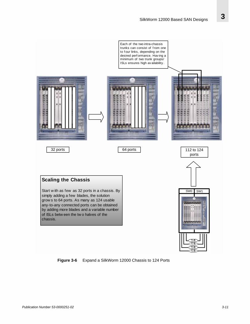
A single chassis, single switch topology starts with 32 ports and can be expanded to as many as 64 ports. Cards can be added to the second logical switch, filling out all 128 ports in a single chassis. For availability and ease of management, the two switches in the chassis should be interconnected by at least two ISLs, which in turn interconnect two separate 16-port card pairs. This scenario of expansion is shown in Figure 3-6. The number of ISLs connecting the two switches can be varied to suit performance requirements. Targeting a 7:1 ratio of node ports to ISLs is reasonable for a starting point.
3-10 Publication Number 53-0000251-02
SilkWorm 12000 Based SAN Designs 3
Figure 3-6 Expand a SilkWorm 12000 Chassis to 124 Ports
Scaling the Chassis
Start w ith as few as 32 ports in a chassis. Bysimply adding a few blades, the solutiongrow s to 64 ports. As many as 124 usableany-to-any connected ports can be obtainedby adding more blades and a variable numberof ISLs betw een the tw o halves of thechassis.
32 ports 64 ports
Each of the two intra-chassistrunks can consist of f rom oneto f our links, depending on thedesired perf ormance. Hav ing aminimum of two trunk groups/ISLs ensures high av ailability .
112 to 124ports
1-41-41-41-4
SW1SW0 SW1SW0
Publication Number 53-0000251-02 3-11

SilkWorm 12000 Based SAN Designs3
The next stage is to establish the foundation for a core/edge fabric. Do so by connecting an additional chassis. Start with as little as 32 ports in the chassis and expand to two 64-port logical switches. Once interconnected, the fabric yields 208 ports. It is essential to identify scaling requirements. If a large fabric of several hundred ports is anticipated, identify the newly connected chassis as the core. A sufficient number of ports should be reserved on the new core for scaling both port count (size) and ISL count (performance). Note that interconnecting the two switches within each chassis is not necessary nor recommend in the core/edge architecture.
If the scaling requirements are lower and locality is possible, a full mesh is also an option. Figure 3-7 illustrates the difference between the partial mesh (which is really a core/edge topology) connection method, and the full mesh. The partial mesh or full mesh can then be expanded into a core/edge topology.
3-12 Publication Number 53-0000251-02
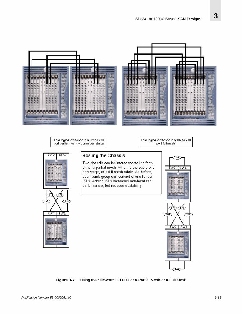
SilkWorm 12000 Based SAN Designs 3
Figure 3-7 Using the SilkWorm 12000 For a Partial Mesh or a Full Mesh
SW1SW0
SW1SW0
SW1SW0
SW1SW0
Publication Number 53-0000251-02 3-13
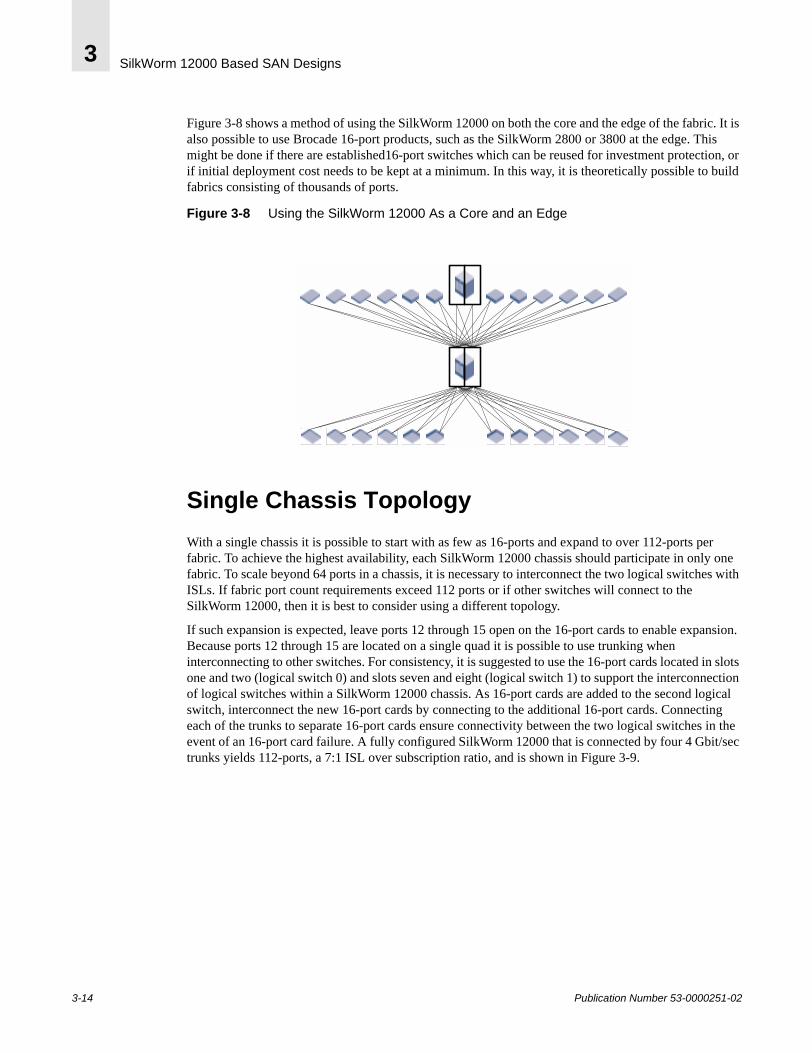
SilkWorm 12000 Based SAN Designs3
Figure 3-8 shows a method of using the SilkWorm 12000 on both the core and the edge of the fabric. It is also possible to use Brocade 16-port products, such as the SilkWorm 2800 or 3800 at the edge. This might be done if there are established16-port switches which can be reused for investment protection, or if initial deployment cost needs to be kept at a minimum. In this way, it is theoretically possible to build fabrics consisting of thousands of ports.
Figure 3-8 Using the SilkWorm 12000 As a Core and an Edge
Single Chassis TopologyWith a single chassis it is possible to start with as few as 16-ports and expand to over 112-ports per fabric. To achieve the highest availability, each SilkWorm 12000 chassis should participate in only one fabric. To scale beyond 64 ports in a chassis, it is necessary to interconnect the two logical switches with ISLs. If fabric port count requirements exceed 112 ports or if other switches will connect to the SilkWorm 12000, then it is best to consider using a different topology.
If such expansion is expected, leave ports 12 through 15 open on the 16-port cards to enable expansion. Because ports 12 through 15 are located on a single quad it is possible to use trunking when interconnecting to other switches. For consistency, it is suggested to use the 16-port cards located in slots one and two (logical switch 0) and slots seven and eight (logical switch 1) to support the interconnection of logical switches within a SilkWorm 12000 chassis. As 16-port cards are added to the second logical switch, interconnect the new 16-port cards by connecting to the additional 16-port cards. Connecting each of the trunks to separate 16-port cards ensure connectivity between the two logical switches in the event of an 16-port card failure. A fully configured SilkWorm 12000 that is connected by four 4 Gbit/sec trunks yields 112-ports, a 7:1 ISL over subscription ratio, and is shown in Figure 3-9.
3-14 Publication Number 53-0000251-02
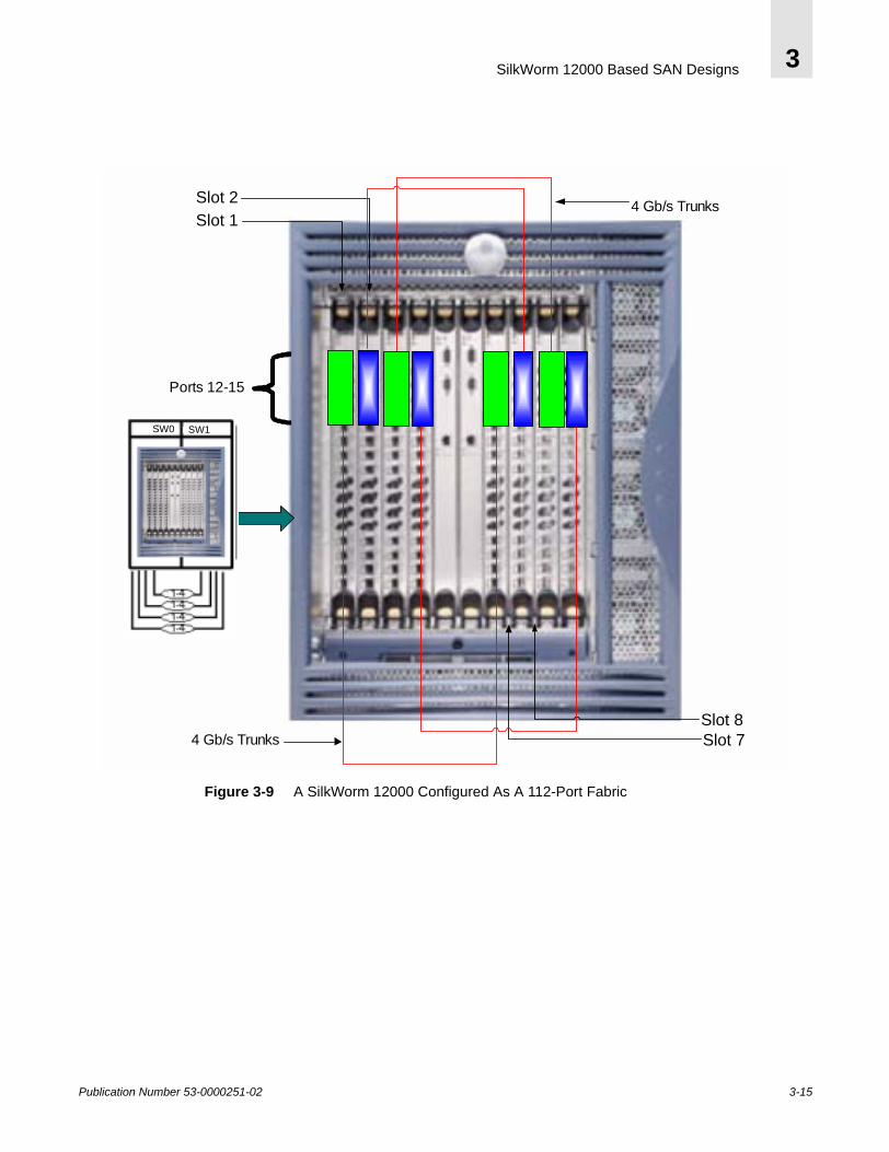
SilkWorm 12000 Based SAN Designs 3
Figure 3-9 A SilkWorm 12000 Configured As A 112-Port Fabric
Ports 12-15
Slot 2Slot 1
4 Gb/s Trunks
4 Gb/s TrunksSlot 8Slot 7
1-41-41-41-4
SW1SW0 SW1SW0
Publication Number 53-0000251-02 3-15
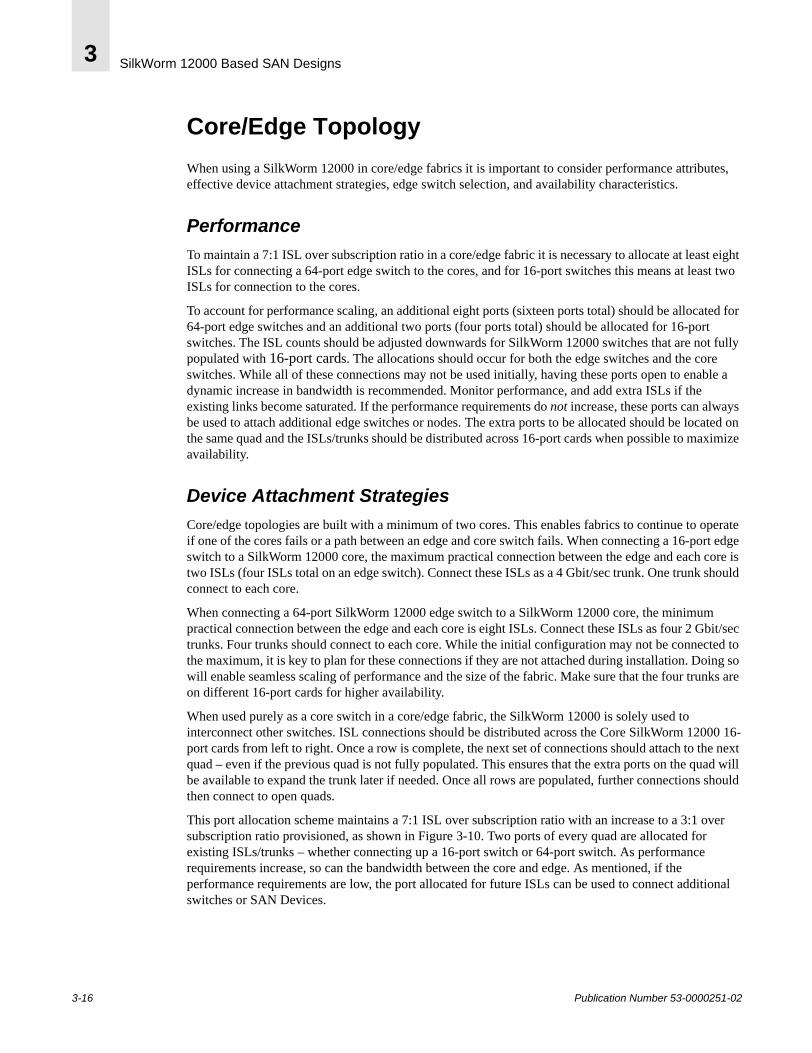
SilkWorm 12000 Based SAN Designs3
Core/Edge TopologyWhen using a SilkWorm 12000 in core/edge fabrics it is important to consider performance attributes, effective device attachment strategies, edge switch selection, and availability characteristics.
PerformanceTo maintain a 7:1 ISL over subscription ratio in a core/edge fabric it is necessary to allocate at least eight ISLs for connecting a 64-port edge switch to the cores, and for 16-port switches this means at least two ISLs for connection to the cores.
To account for performance scaling, an additional eight ports (sixteen ports total) should be allocated for 64-port edge switches and an additional two ports (four ports total) should be allocated for 16-port switches. The ISL counts should be adjusted downwards for SilkWorm 12000 switches that are not fully populated with 16-port cards. The allocations should occur for both the edge switches and the core switches. While all of these connections may not be used initially, having these ports open to enable a dynamic increase in bandwidth is recommended. Monitor performance, and add extra ISLs if the existing links become saturated. If the performance requirements do not increase, these ports can always be used to attach additional edge switches or nodes. The extra ports to be allocated should be located on the same quad and the ISLs/trunks should be distributed across 16-port cards when possible to maximize availability.
Device Attachment StrategiesCore/edge topologies are built with a minimum of two cores. This enables fabrics to continue to operate if one of the cores fails or a path between an edge and core switch fails. When connecting a 16-port edge switch to a SilkWorm 12000 core, the maximum practical connection between the edge and each core is two ISLs (four ISLs total on an edge switch). Connect these ISLs as a 4 Gbit/sec trunk. One trunk should connect to each core.
When connecting a 64-port SilkWorm 12000 edge switch to a SilkWorm 12000 core, the minimum practical connection between the edge and each core is eight ISLs. Connect these ISLs as four 2 Gbit/sec trunks. Four trunks should connect to each core. While the initial configuration may not be connected to the maximum, it is key to plan for these connections if they are not attached during installation. Doing so will enable seamless scaling of performance and the size of the fabric. Make sure that the four trunks are on different 16-port cards for higher availability.
When used purely as a core switch in a core/edge fabric, the SilkWorm 12000 is solely used to interconnect other switches. ISL connections should be distributed across the Core SilkWorm 12000 16-port cards from left to right. Once a row is complete, the next set of connections should attach to the next quad – even if the previous quad is not fully populated. This ensures that the extra ports on the quad will be available to expand the trunk later if needed. Once all rows are populated, further connections should then connect to open quads.
This port allocation scheme maintains a 7:1 ISL over subscription ratio with an increase to a 3:1 over subscription ratio provisioned, as shown in Figure 3-10. Two ports of every quad are allocated for existing ISLs/trunks – whether connecting up a 16-port switch or 64-port switch. As performance requirements increase, so can the bandwidth between the core and edge. As mentioned, if the performance requirements are low, the port allocated for future ISLs can be used to connect additional switches or SAN Devices.
3-16 Publication Number 53-0000251-02
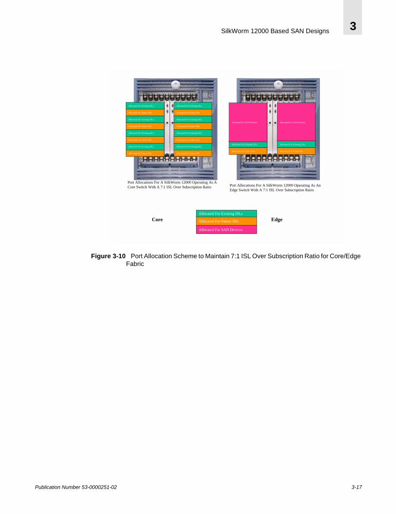
SilkWorm 12000 Based SAN Designs 3
Figure 3-10 Port Allocation Scheme to Maintain 7:1 ISL Over Subscription Ratio for Core/Edge Fabric
Allocated For Existing ISLs
Allocated For Future ISls
Allocated For SAN Devices
Port Allocations For A SilkWorm 12000 Operating As An Edge Switch With A 7:1 ISL Over Subscription Ratio
Allocated For SAN Devices
Allocated For Existing ISLs
Allocated For Future ISls
Allocated For SAN Devices
Port Allocations For A SilkWorm 12000 Operating As A Core Switch With A 7:1 ISL Over Subscription Ratio
Allocated For Existing ISLs
Allocated For Future ISls
Allocated For Existing ISLs
Allocated For Future ISls
Allocated For Existing ISLs
Allocated For Future ISls
Allocated For Existing ISLs
Allocated For Future ISls
Allocated For Existing ISLs
Allocated For Future ISls
Allocated For Existing ISLs
Allocated For Future ISls
Allocated For Existing ISLs
Allocated For Future ISls
Allocated For Existing ISLs
Allocated For Future ISls
Allocated For Existing ISLs
Allocated For Future ISls
Core Edge
Publication Number 53-0000251-02 3-17
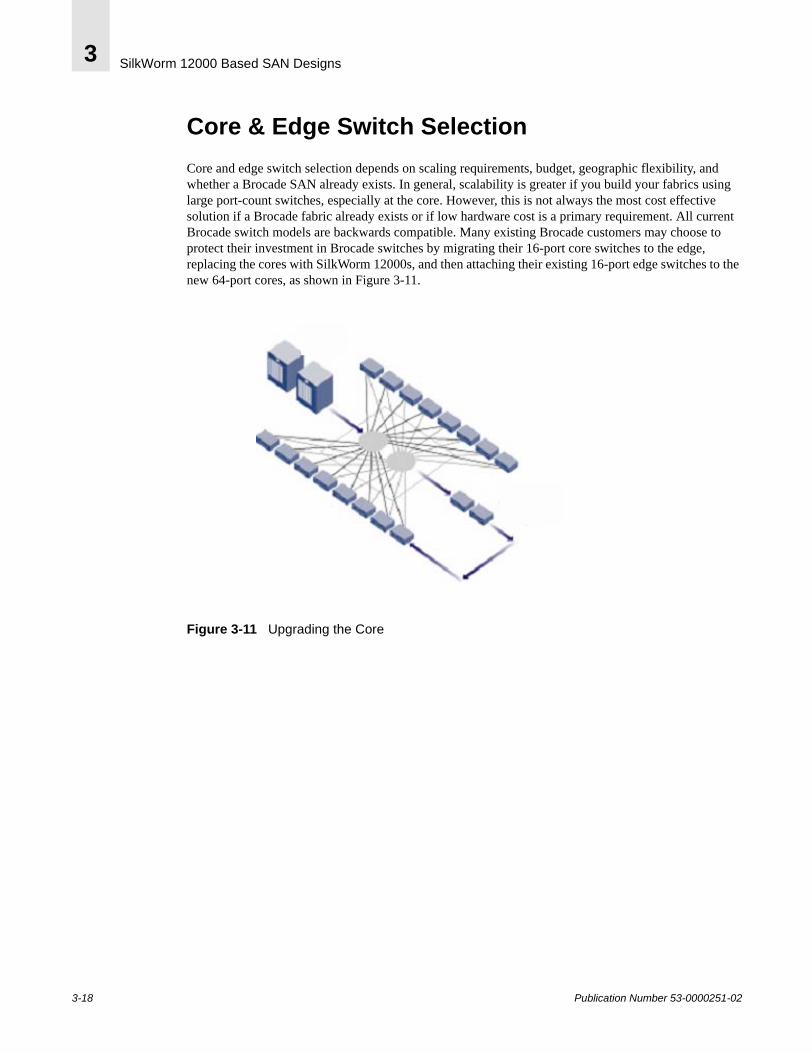
SilkWorm 12000 Based SAN Designs3
Core & Edge Switch SelectionCore and edge switch selection depends on scaling requirements, budget, geographic flexibility, and whether a Brocade SAN already exists. In general, scalability is greater if you build your fabrics using large port-count switches, especially at the core. However, this is not always the most cost effective solution if a Brocade fabric already exists or if low hardware cost is a primary requirement. All current Brocade switch models are backwards compatible. Many existing Brocade customers may choose to protect their investment in Brocade switches by migrating their 16-port core switches to the edge, replacing the cores with SilkWorm 12000s, and then attaching their existing 16-port edge switches to the new 64-port cores, as shown in Figure 3-11.
Figure 3-11 Upgrading the Core
3-18 Publication Number 53-0000251-02
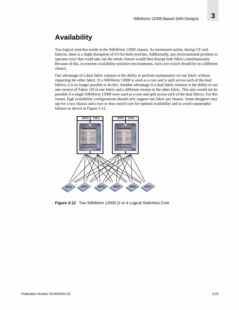
SilkWorm 12000 Based SAN Designs 3
AvailabilityTwo logical switches reside in the SilkWorm 12000 chassis. As mentioned earlier, during CP card failover, there is a slight disruption of I/O for both switches. Additionally, any environmental problem or operator error that could take out the whole chassis would then disrupt both fabrics simultaneously. Because of this, in extreme availability-sensitive environments, each core switch should be on a different chassis.
One advantage of a dual fabric solution is the ability to perform maintenance on one fabric without impacting the other fabric. If a SilkWorm 12000 is used as a core and is split across each of the dual fabrics, it is no longer possible to do this. Another advantage to a dual fabric solution is the ability to run one version of Fabric OS in one fabric and a different version in the other fabric. This also would not be possible if a single SilkWorm 12000 were used as a core and split across each of the dual fabrics. For this reason, high availability configurations should only support one fabric per chassis. Some designers may opt for a two chassis and a two or four switch core for optimal availability and to avoid catastrophic failures as shown in Figure 3-12.
Figure 3-12 Two SilkWorm 12000 (2 or 4 Logical Switches) Core
38003800 3800380038003800
SW1SW0SW1SW0
Publication Number 53-0000251-02 3-19

SilkWorm 12000 Based SAN Designs3
Large Fabric Support LevelsBrocade is currently testing and validating fabrics consisting of hundreds of ports and has plans for testing multi-thousand port fabrics. The ultimate limitation in fabric design as defined in the Fibre Channel standards is 239 physical switches. As a practical matter, no vendor has yet tested networks of this size due to the expense and complexity of implementing such a network. The current practical switch-count limit is lower than 239 switches, based upon empirical testing. Another limit on SAN design is hop count. The hop count between any two devices is limited to seven hops.
Brocade partners with many OEMs and re-sellers who supply switches to end-users. Many of these partners provide direct support for the switches they sell. These partners extensively test and support specific configurations, including switches, storage, HBAs, and other SAN components. In some cases, the large fabric configurations supported by Brocade partners will differ from the guidelines Brocade presents in this document. In fact, several Brocade switch partners have developed their own SAN design guidelines, including in-depth support matrixes that specify support configurations and firmware versions.
Those partners who do not provide direct switch support sell to their customers Brocade Service Plans with the switches. For more information on support for SilkWorm switches, contact the switch provider. For more information on Brocade Service Plans, visit www.brocade.com.
Table 3-1 details the current Brocade recommended support levels for large fabrics. If a certain level of Fabric OS does not appear in Table 3-1, it does not mean that version will not work or is not supported. The table simply reflects testing levels as of this writing, but it is possible that a version that has not undergone this testing will work without issues. If a required firmware version is not on this table, check with the service provider.
Please contact your switch service provider or Brocade Systems Engineer to identify the current fabric size support levels or to see if it is possible to obtain support for fabrics that exceed current support levels.
Table 3-1 Large Fabric Support Levels
Number of SilkWorm 12000 Logical Switches
Number of 2000s and 3000s
Total Number of Switches
Fabric OS
4 Not to exceed 24 28 12000: 4.0.03000: 3.0.2c2000: 2.6.0c
3-20 Publication Number 53-0000251-02
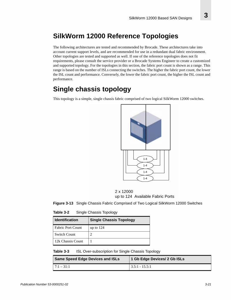
SilkWorm 12000 Based SAN Designs 3
SilkWorm 12000 Reference TopologiesThe following architectures are tested and recommended by Brocade. These architectures take into account current support levels, and are recommended for use in a redundant dual fabric environment. Other topologies are tested and supported as well. If one of the reference topologies does not fit requirements, please consult the service provider or a Brocade Systems Engineer to create a customized and supported topology. For the topologies in this section, the fabric port count is shown as a range. This range is based on the number of ISLs connecting the switches. The higher the fabric port count, the lower the ISL count and performance. Conversely, the lower the fabric port count, the higher the ISL count and performance.
Single chassis topologyThis topology is a simple, single chassis fabric comprised of two logical SilkWorm 12000 switches.
Figure 3-13 Single Chassis Fabric Comprised of Two Logical SilkWorm 12000 Switches
Table 3-2 Single Chassis Topology
Identification Single Chassis Topology
Fabric Port Count up to 124
Switch Count 2
12k Chassis Count 1
Table 3-3 ISL Over-subscription for Single Chassis Topology
Same Speed Edge Devices and ISLs 1 Gb Edge Devices/ 2 Gb ISLs
7:1 – 31:1 3.5:1 - 15.5:1
2 x 12000up to 124 Available Fabric Ports
1-4
1-4
1-4
1-4
Publication Number 53-0000251-02 3-21
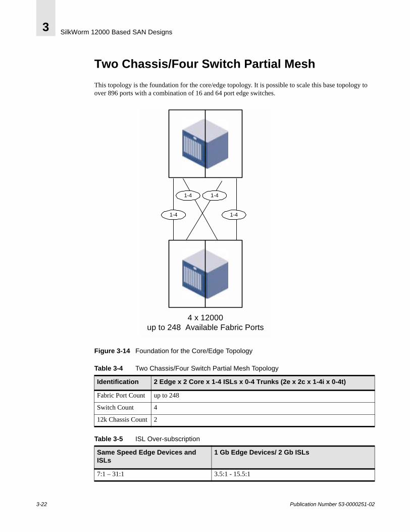
SilkWorm 12000 Based SAN Designs3
Two Chassis/Four Switch Partial MeshThis topology is the foundation for the core/edge topology. It is possible to scale this base topology to over 896 ports with a combination of 16 and 64 port edge switches.
Figure 3-14 Foundation for the Core/Edge Topology
4 x 12000up to 248 Available Fabric Ports
1-41-4
1-41-4
Table 3-4 Two Chassis/Four Switch Partial Mesh Topology
Identification 2 Edge x 2 Core x 1-4 ISLs x 0-4 Trunks (2e x 2c x 1-4i x 0-4t)
Fabric Port Count up to 248
Switch Count 4
12k Chassis Count 2
Table 3-5 ISL Over-subscription
Same Speed Edge Devices and ISLs
1 Gb Edge Devices/ 2 Gb ISLs
7:1 – 31:1 3.5:1 - 15.5:1
3-22 Publication Number 53-0000251-02
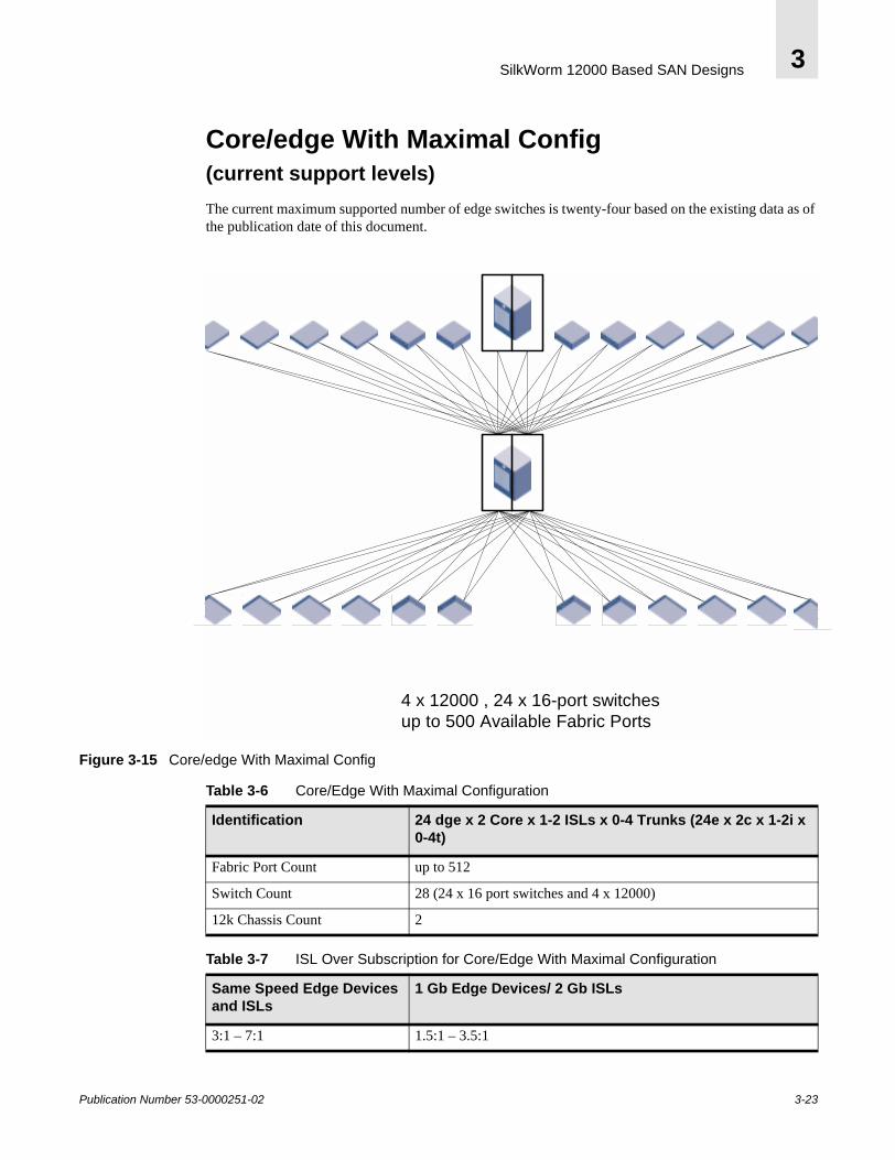
SilkWorm 12000 Based SAN Designs 3
Core/edge With Maximal Config (current support levels)The current maximum supported number of edge switches is twenty-four based on the existing data as of the publication date of this document.
Figure 3-15 Core/edge With Maximal Config
4 x 12000 , 24 x 16-port switchesup to 500 Available Fabric Ports
Table 3-6 Core/Edge With Maximal Configuration
Identification 24 dge x 2 Core x 1-2 ISLs x 0-4 Trunks (24e x 2c x 1-2i x 0-4t)
Fabric Port Count up to 512
Switch Count 28 (24 x 16 port switches and 4 x 12000)
12k Chassis Count 2
Table 3-7 ISL Over Subscription for Core/Edge With Maximal Configuration
Same Speed Edge Devices and ISLs
1 Gb Edge Devices/ 2 Gb ISLs
3:1 – 7:1 1.5:1 – 3.5:1
Publication Number 53-0000251-02 3-23

SilkWorm 12000 Based SAN Designs3
3-24 Publication Number 53-0000251-02
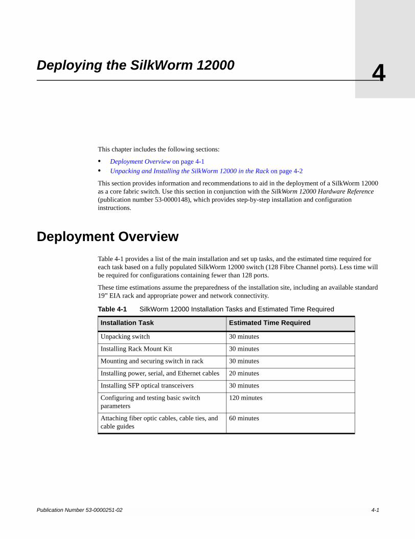
Publication Number 53-0000251-02
4
Deploying the SilkWorm 12000This chapter includes the following sections:
• Deployment Overview on page 4-1• Unpacking and Installing the SilkWorm 12000 in the Rack on page 4-2
This section provides information and recommendations to aid in the deployment of a SilkWorm 12000 as a core fabric switch. Use this section in conjunction with the SilkWorm 12000 Hardware Reference (publication number 53-0000148), which provides step-by-step installation and configuration instructions.
Deployment OverviewTable 4-1 provides a list of the main installation and set up tasks, and the estimated time required for each task based on a fully populated SilkWorm 12000 switch (128 Fibre Channel ports). Less time will be required for configurations containing fewer than 128 ports.
These time estimations assume the preparedness of the installation site, including an available standard 19” EIA rack and appropriate power and network connectivity.
Table 4-1 SilkWorm 12000 Installation Tasks and Estimated Time Required
Installation Task Estimated Time Required
Unpacking switch 30 minutes
Installing Rack Mount Kit 30 minutes
Mounting and securing switch in rack 30 minutes
Installing power, serial, and Ethernet cables 20 minutes
Installing SFP optical transceivers 30 minutes
Configuring and testing basic switch parameters
120 minutes
Attaching fiber optic cables, cable ties, and cable guides
60 minutes
4-1
Deploying the SilkWorm 120004
Unpacking and Installing the SilkWorm 12000 in the Rack
This section provides instructions for unpacking the SilkWorm 12000, site planning, installing the switch in an EIA rack, and tips on cable management.
The SilkWorm 12000 Rack Mount Kit is designed for use in a standard 19 inch EIA rack that has rack rails with the “square” type of holes.
Unpacking the SwitchDue to the weight and size of the SilkWorm 12000, it is important to plan where to unpack it and how to transport it. For example, it might be easier to unpack it in the shipping room and use a cart or mobile hydraulic lift to bring it to the rack, or to transport to the rack while it is still in the packing crate, using a pallet jack, and then unpack it. The crate on a pallet jack will fit through doorways wider than 36 inches. To minimize the amount of vibration during transportation, bring the packing crate as close as possible to the final destination before unpacking the switch.
To unpack the switch and prepare it for installation:
1. Remove the outer shell or shipping case.
2. Remove the static bag.
3. Unscrew the shipping screws from the pallet.
4. Remove the front door and cable management tray to prevent breakage while the switch is installed in the rack, and set aside.
Site Planning
ElectricalThe SilkWorm 12000 requires two dedicated branch circuits, each protected by a circuit breaker in accordance with local electrical codes, and terminated with a receptacle appropriate to the power cord. Only use power outlets that were installed by a licensed electrician. Verify that the supply circuit, line fusing, and wire size are adequate according to the electrical rating on the switch nameplate. The voltage required is 200 to 240 VAC (in the USA the available voltage is usually 208 or 240 VAC, the receptacles are usually NEMA L6-20R, and the branch circuit breakers are usually rated at 20 amps each).
General location• Placing the switch on the floor is not recommended because this would prevent using the cable
management tray and would make cable routing unnecessarily difficult.• To ensure adequate cooling, install the switch with the port side of the switch facing the aisle into
which exhaust air is released (usually the “service” aisle). This prevents the switch fans from pulling in heated exhaust air, since the air enters through the vents in the back of the chassis and exits from the vent in the top of the front of the chassis.
• The air intake and exhaust vents require a minimum of two inches of airspace.
4-2 Publication Number 53-0000251-02
Deploying the SilkWorm 12000 4
EIA RackPlan the location of the switch in the rack carefully to minimize the chance of having to re-rack the switch.
• The SilkWorm 12000 requires an EIA rack space that is 14 rack units high, 30 inches deep, and 19 inches wide.
• If installing the SilkWorm 12000 in a closed or multi-rack assembly, ensure the air temperature measured at the blower inlet does not exceed 40 degrees Celsius at any time.
• Verify that the installed switch chassis does not unbalance the rack or exceed the rack’s weight limits.
• Verify that all equipment installed in the rack has a reliable branch circuit ground connection.• Mechanically secure the EIA Rack before installing the switch, to ensure stability while the switch
is mounted and in case the rack is accidentally moved afterwards.• If possible leave a minimum of two rack units beneath each SilkWorm 12000 to allow for cable
management.
Warning: A fully populated SilkWorm 12000 weighs approximately 250 lbs; and requires a minimum of two people and a hydraulic lift to safely install it. The hydraulic lift must be capable of extending at least 40 inches.Before installing the switch, ensure that the rack is balanced and mechanically secured, and that the weight of the switch will not exceed the weight limits of the rack.If two SilkWorm 12000 switches will be mounted in the same rack, install the lower switch first, recheck rack stability, and then have a third person present to monitor rack stability while mounting the second switch.
Installing the Rack Mount KitTips for installing the switch in the rack:
• Plan the positioning of the 4 x 10-32 Cage Nuts on the rack rails to ensure that the screw holes being used will line up with the holes on the front of the chassis. To align these Cage Nuts with the front of the chassis place them in one of the following number of holes from the top of the “shelf” like rail. (2,4, 14,16, 26, 28, 34). For example one option is to place the Cage Nuts in the second and the fourth hole on the EIA rail from the top of the “shelf”. This positioning should provide the necessary pattern in order to match the holes on the front of the chassis. If the retainer nuts are found to be incorrectly positioned after the switch is already mounted in the rack, the switch must be removed from the rack in order to reposition the retainer nuts (see Figure 4-1).
• If the switch will be located at the bottom of the rack, the top of the shelf-like brackets must be attached a minimum of four rack units off the ground, to allow adequate space below the switch for cable management.
• When attaching the shelf brackets to the rack, it is easiest to work from the back since this provides a better vantage point for ensuring correct alignment. Also make sure to insert the square washers into the holes before attaching the bottom “shelf”. This will center the mounting screws and therefore correctly position the “shelf” so when it is time to secure the UPPER Rack Mount Brackets they will also be in alignment with the EIA rail.
• Attach the notched portion of the shelf brackets to the front of the rack as shown in Figure 4-1. This allows the power cables to be routed to either side of the switch.
Publication Number 53-0000251-02 4-3

Deploying the SilkWorm 120004
• Install the parts that attach directly to the chassis before mounting the switch in the rack.• Wait to attach the Upper Rack Mount Brackets to the rack rails until the chassis has been placed onto
the two shelf-like brackets.
Note: Do not use the power supply or blower assembly bays to gain leverage on the switch. These areas are not designed to handle this type of pressure, and will become damaged. If handling the switch becomes too difficult, bring in an additional person to assist with the racking process.
Figure 4-1 SilkWorm 12000 Racking Schematic
Reinstalling the Chassis Door and Cable Management TrayOnce the switch is installed in the rack, reinstall the chassis door and cable management tray.
Use a manual screwdriver when reattaching the cable management tray, because it can be damaged by the excessive torque from a cordless type screwdriver.
Note: Do not connect the switch to the network until the IP address is correctly set. For instructions on starting and configuring the switch, refer the SilkWorm 12000 Hardware Reference.
4-4 Publication Number 53-0000251-02
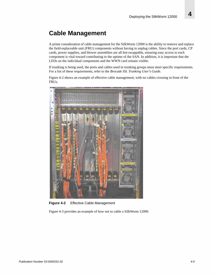
Deploying the SilkWorm 12000 4
Cable ManagementA prime consideration of cable management for the SilkWorm 12000 is the ability to remove and replace the field-replaceable unit (FRU) components without having to unplug cables. Since the port cards, CP cards, power supplies, and blower assemblies are all hot-swappable, ensuring easy access to each component is vital toward contributing to the uptime of the SAN. In addition, it is important that the LEDs on the individual components and the WWN card remain visible.
If trunking is being used, the ports and cables used in trunking groups must meet specific requirements. For a list of these requirements, refer to the Brocade ISL Trunking User’s Guide.
Figure 4-2 shows an example of effective cable management, with no cables crossing in front of the FRUs.
Figure 4-2 Effective Cable Management
Figure 4-3 provides an example of how not to cable a SilkWorm 12000.
Publication Number 53-0000251-02 4-5
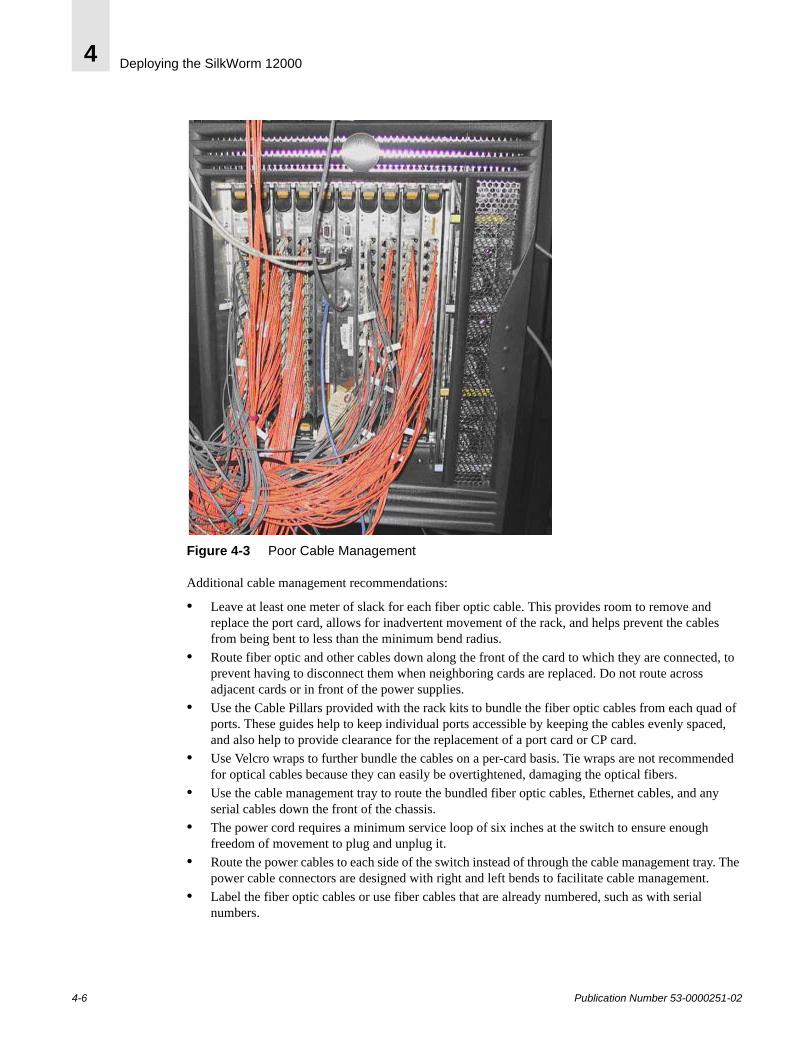
Deploying the SilkWorm 120004
Figure 4-3 Poor Cable Management
Additional cable management recommendations:
• Leave at least one meter of slack for each fiber optic cable. This provides room to remove and replace the port card, allows for inadvertent movement of the rack, and helps prevent the cables from being bent to less than the minimum bend radius.
• Route fiber optic and other cables down along the front of the card to which they are connected, to prevent having to disconnect them when neighboring cards are replaced. Do not route across adjacent cards or in front of the power supplies.
• Use the Cable Pillars provided with the rack kits to bundle the fiber optic cables from each quad of ports. These guides help to keep individual ports accessible by keeping the cables evenly spaced, and also help to provide clearance for the replacement of a port card or CP card.
• Use Velcro wraps to further bundle the cables on a per-card basis. Tie wraps are not recommended for optical cables because they can easily be overtightened, damaging the optical fibers.
• Use the cable management tray to route the bundled fiber optic cables, Ethernet cables, and any serial cables down the front of the chassis.
• The power cord requires a minimum service loop of six inches at the switch to ensure enough freedom of movement to plug and unplug it.
• Route the power cables to each side of the switch instead of through the cable management tray. The power cable connectors are designed with right and left bends to facilitate cable management.
• Label the fiber optic cables or use fiber cables that are already numbered, such as with serial numbers.
4-6 Publication Number 53-0000251-02

Deploying the SilkWorm 12000 4
• Use a spreadsheet to track which devices are connected to which switch, port card, and port in the SilkWorm 12000. The serial numbers or other identifiers of the fiber optic cables can also be tracked.
• Keep the chassis door closed to protect the cables from inadvertent movement.
Publication Number 53-0000251-02 4-7

Deploying the SilkWorm 120004
4-8 Publication Number 53-0000251-02
Publication Number 53-0000251-02
5
Configuring the SilkWorm 12000This chapter includes the following sections:
• Configuring the SilkWorm 12000 on page 5-1• Configuring IP Addresses on page 5-3• Configuring the Switch Name on page 5-5
This chapter provides information and recommendations to aid in the deployment of a SilkWorm 12000 as a core fabric switch. Use this chapter in conjunction with the SilkWorm 12000 Hardware Reference (publication number 53-0000148), which provides step-by-step configuration instructions.
Configuring the SilkWorm 12000This section describes the basic steps required for initial configuration of the SilkWorm 12000. Refer to the SilkWorm 12000 Hardware Reference for step-by-step instructions on how to start up and configure the SilkWorm 12000.
All configuration commands must be entered through the active CP card. The best way to configure the switch is to establish a telnet session into either of the logical switch IP addresses, which always connects the user to the active CP card.
The configure command requires that the switch be disabled beforehand, using the switchDisable command. The switch can then be re-enabled afterwards using the switchEnable command.
A routine backup of the configuration is recommended, to ensure a current configuration is available for uploading to a replacement switch.
Each time the switch is powered on, it performs POST (Power On Self Test) by default. POST lasts from 6 to 9 minutes, and is complete when LED activity returns to the standard healthy display (for information about LED patterns, refer to the SilkWorm 12000 Hardware Reference).
Basic configuration steps:1. Log into switch.2. Verify hardware through Power On Self Tests.3. Optional: Verify hardware using diagnostic tests (see below).4. Set up IP addresses.5. Specify switch name.6. Specify domain ID.7. Enable software licenses as necessary.
5-1
Configuring the SilkWorm 120005
Logging into the SilkWorm 120001. Check the LEDs to verify that the switch is on and POST has completed (the lit LEDs should be
displaying green; for specific descriptions of LED patterns, refer to the SilkWorm 12000 Hardware Reference).
2. Use the serial cable provided with the SilkWorm 12000 to connect the lower serial port on the active CP card to a computer workstation.
The haShow command can be used to determine which of the CP cards is active. The active CP card is usually the one that has been continuously functioning for the longest period of time.
The terminal serial port is intended primarily for use during the initial setting of the IP address, and for service purposes.
3. Access the switch using a terminal emulator application (such as HyperTerminal in a Windows environment, or TERM in a UNIX Environment). For parameters, refer to the SilkWorm 12000 Hardware Reference.
4. Log in as the administrative user. The default logon is “admin” and the default password is “password”.
At the initial login the user is prompted to enter a new Admin, User, and Root level password. Passwords must be a total of 8 to 40 characters long, and should include a combination of numbers and upper case and lower case letters to ensure security. To skip modifying the password, press CTRL-C.
Note: Although root level access is available on the SilkWorm 12000, use with caution to prevent unintentional modifications to the function of the switch.
Note: For the initial powerup and initialization sequence of SilkWorm 12000 ensure that a port blades occupies slot 1.
Using Diagnostic Tests to Verify Hardware (Optional)POST (power on self test) is performed by default each time the switch is booted. In addition, manufacturing-level diagnostic tests are available through two commands, SystemTest and Switchburnin.sh. These tests are appropriate to perform after setting up the switch but before using it in daily operations.
• SystemTest: This tests the internal loopback plugs on a per-slot basis, and takes approximately two hours to complete on a chassis that contains eight 16-port cards. No additional items are required to perform this test. It is available to the admin logon.
Sw0:admin> systemtest [[ -slot ] slot ]
5-2 Publication Number 53-0000251-02
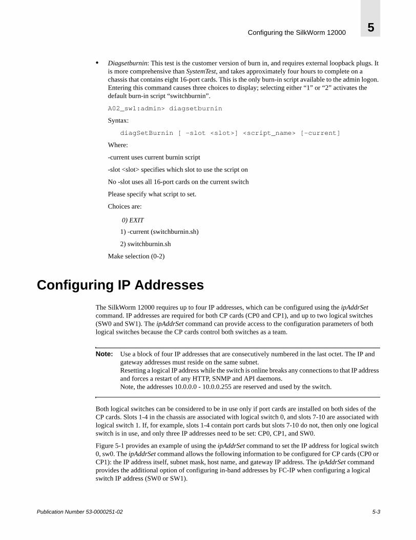
Configuring the SilkWorm 12000 5
• Diagsetburnin: This test is the customer version of burn in, and requires external loopback plugs. It is more comprehensive than SystemTest, and takes approximately four hours to complete on a chassis that contains eight 16-port cards. This is the only burn-in script available to the admin logon. Entering this command causes three choices to display; selecting either “1” or “2” activates the default burn-in script “switchburnin”.
A02_sw1:admin> diagsetburnin
Syntax:
diagSetBurnin [ -slot <slot>] <script_name> [-current]
Where:
-current uses current burnin script
-slot <slot> specifies which slot to use the script on
No -slot uses all 16-port cards on the current switch
Please specify what script to set.
Choices are:
0) EXIT
1) -current (switchburnin.sh)
2) switchburnin.sh
Make selection (0-2)
Configuring IP AddressesThe SilkWorm 12000 requires up to four IP addresses, which can be configured using the ipAddrSet command. IP addresses are required for both CP cards (CP0 and CP1), and up to two logical switches (SW0 and SW1). The ipAddrSet command can provide access to the configuration parameters of both logical switches because the CP cards control both switches as a team.
Note: Use a block of four IP addresses that are consecutively numbered in the last octet. The IP and gateway addresses must reside on the same subnet.Resetting a logical IP address while the switch is online breaks any connections to that IP address and forces a restart of any HTTP, SNMP and API daemons.Note, the addresses 10.0.0.0 - 10.0.0.255 are reserved and used by the switch.
Both logical switches can be considered to be in use only if port cards are installed on both sides of the CP cards. Slots 1-4 in the chassis are associated with logical switch 0, and slots 7-10 are associated with logical switch 1. If, for example, slots 1-4 contain port cards but slots 7-10 do not, then only one logical switch is in use, and only three IP addresses need to be set: CP0, CP1, and SW0.
Figure 5-1 provides an example of using the ipAddrSet command to set the IP address for logical switch 0, sw0. The ipAddrSet command allows the following information to be configured for CP cards (CP0 or CP1): the IP address itself, subnet mask, host name, and gateway IP address. The ipAddrSet command provides the additional option of configuring in-band addresses by FC-IP when configuring a logical switch IP address (SW0 or SW1).
Publication Number 53-0000251-02 5-3
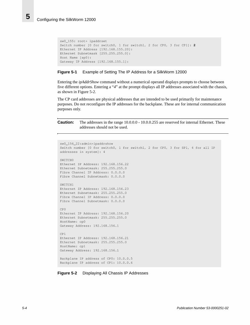
Configuring the SilkWorm 120005
Figure 5-1 Example of Setting The IP Address for a SilkWorm 12000
Entering the ipAddrShow command without a numerical operand displays prompts to choose between five different options. Entering a “4” at the prompt displays all IP addresses associated with the chassis, as shown in Figure 5-2.
The CP card addresses are physical addresses that are intended to be used primarily for maintenance purposes. Do not reconfigure the IP addresses for the backplane. These are for internal communication purposes only.
Caution: The addresses in the range 10.0.0.0 - 10.0.0.255 are reserved for internal Ethernet. These addresses should not be used.
Figure 5-2 Displaying All Chassis IP Addresses
sw0_155: root> ipaddrsetSwitch number [0 for switch0, 1 for switch1, 2 for CP0, 3 for CP1]: 2Ethernet IP Address [192.168.155.20]:Ethernet Subnetmask [255.255.255.0]:Host Name [sp0}:Gateway IP Address [192.168.155.1]:
sw0_156_22:admin>ipaddrshowSwitch number [0 for switch0, 1 for switch1, 2 for CP0, 3 for SP1, 4 for all IP addresses in system]: 4
SWITCH0Ethernet IP Address: 192.168.156.22Ethernet Subnetmask: 255.255.255.0Fibre Channel IP Address: 0.0.0.0Fibre Channel Subnetmask: 0.0.0.0
SWITCH1Ethernet IP Address: 192.168.156.23Ethernet Subnetmask: 255.255.255.0Fibre Channel IP Address: 0.0.0.0Fibre Channel Subnetmask: 0.0.0.0
CP0Ethernet IP Address: 192.168.156.20Ethernet Subnetmask: 255.255.255.0HostName: cp0Gateway Address: 192.168.156.1
CP1Ethernet IP Address: 192.168.156.21Ethernet Subnetmask: 255.255.255.0HostName: cp1Gateway Address: 192.168.156.1
Backplane IP address of CP0: 10.0.0.5Backplane IP address of CP1: 10.0.0.6
5-4 Publication Number 53-0000251-02
Configuring the SilkWorm 12000 5
Configuring the Switch NameUse a consistent switch naming convention when naming the switch, to allow easy identification of the physical switch with the SAN, such as <fabric><domain #>-<logical switch name>.
Consider whether to include the following information in the name:
• The site or building in which the switch is located.• The floor or room in which the switch is located.• The rack in which the switch is located.• Whether the switch is a core or edge switch.• The logical switch name, such as SW0 or SW1.• The organization or project to which the switch belongs.• If redundant fabrics are being used, an identifier for complementary fabrics.
The logical switches can be named by using the command switchName. The CP cards can be named using the command ipAddrSet.
Setting the Domain IDEach switch in the fabric must have a unique Domain ID. To simplify switch identification, use consecutive domain IDs for logical switches in the same SilkWorm 12000. For example, logical switch SW0 could be set to domain 1, and logical switch SW1 to domain 2. Domain IDs can be set using the configure command.
It is also possible to allow the domain IDs to be automatically set. Both logical switches in the SilkWorm 12000 have a default domain ID of “1”.
Note: Both logical switches default to the same domain ID (1). This can cause a domain ID conflict if both logical switches are enabled and connected to the fabric at the same time. Connecting these logical switches together while at least one is disabled or powered down will not result in a Domain ID conflict.
Enabling Software LicensesDepending on the vendor agreement, certain licenses may have been factory installed. To determine which licenses are currently enabled, enter the licenseShow command.
The 64-bit chassis ID is required to obtain a license, and is used to activate licenses for both logical switches within the SilkWorm 12000. The chassis ID is available through the command licenseidShow.
Both the licenseShow and licenseidShow commands must be entered through the active CP card.
Publication Number 53-0000251-02 5-5
Configuring the SilkWorm 120005
Return Switches to Default SettingsIf you desire to return your SilkWorm 12000 configuration settings to factory default use the “configdefault” command. The IP address and Zoning configuration will be unchanged.
Each logical switch must be disabled using the “switchdisable” command in order to administer the “configdefault” command.
Once configdefault finishes execution, re-enable the switch with switchenable. The configuration information will be automatically updated from the active to the standby CP. Although not required, it is highly recommeded to do a switchreboot after the switchenable. If the default settings are desired on the second logical switch, these steps must be repeated.
Note: For the initial powerup and initialization sequence of SilkWorm 12000 ensure that a port blades occupies slot 1.
5-6 Publication Number 53-0000251-02
Publication Number 53-0000251-02
6
SilkWorm 12000 Management InterfacesThis chapter includes the following sections:
• Telnet on page 6-1• Web Tools on page 6-8• Fabric Manager 3.0 on page 6-16
The SilkWorm 12000 allows for the user to access and manage the switch in multiple ways. The ability to manage the SilkWorm 12000 through different methods enables flexibility for the administrators to accomplish their task. The interfaces that are available to choose from are telnet, serial console, SNMP, Web Tools, and Fabric Manager 3.0. Each one of these interfaces adds a unique method to management of the SilkWorm 12000.
Below is a listing of each management interface. This should provide a general understanding of what each component is capable of, the new features introduced into each interface, and sample implementations of each. Significant differences between the SilkWorm 12000 and previous generations of switches are also highlighted.
TelnetTelnet is one of the primary interfaces of managing the switch. Telnet allows for the user to manage the switch through a command line interface (CLI) over a network connection. The use of a CLI allows the user to systematically step through commands. Although this may be tedious, it allows for the most accurate way of managing the switch.
When using the telnet interface, by default there is a 10 minute timeout value that is set. This will allow for idle telnet sessions be automatically logged out after a specified time. This value must be greater than zero. A value of zero is equivelant to an infinate timeout value.
Below is a list of the new/revised commands to be aware of in Fabric OS 4.0x. A complete detailed list of telnet commands is available in Brocade Fabric OS Reference v3.0/4.0 (publication number: 53-0000182-01).
Note: When using the CLI make sure to login to the logical switch when executing the command. This will guarantee that the commands are being executed from the Active CP card.
chassisshow: This command inventories and displays the field replaceable unit (FRU) header content for each object in the chassis.
diagHelp: Displays all the currently available diagnostic commands. There are several additional diagnostic commands that may change. Please refer to Troubleshooting/Support on page 8-1 for more information on what diagnostic commands will be of use.
6-1
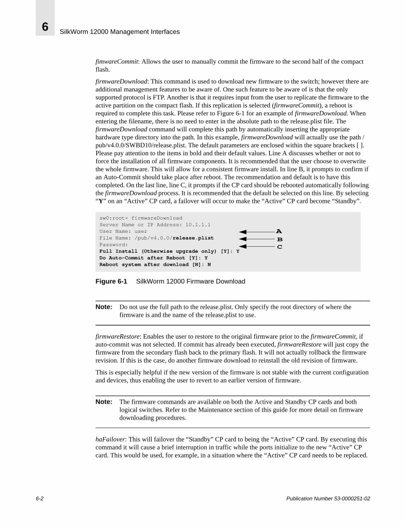
SilkWorm 12000 Management Interfaces6
fimwareCommit: Allows the user to manually commit the firmware to the second half of the compact flash.
firmwareDownload: This command is used to download new firmware to the switch; however there are additional management features to be aware of. One such feature to be aware of is that the only supported protocol is FTP. Another is that it requires input from the user to replicate the firmware to the active partition on the compact flash. If this replication is selected (firmwareCommit), a reboot is required to complete this task. Please refer to Figure 6-1 for an example of firmwareDownload. When entering the filename, there is no need to enter in the absolute path to the release.plist file. The firmwareDownload command will complete this path by automatically inserting the appropriate hardware type directory into the path. In this example, firmwareDownload will actually use the path /pub/v4.0.0/SWBD10/release.plist. The default parameters are enclosed within the square brackets [ ]. Please pay attention to the items in bold and their default values. Line A discusses whether or not to force the installation of all firmware components. It is recommended that the user choose to overwrite the whole firmware. This will allow for a consistent firmware install. In line B, it prompts to confirm if an Auto-Commit should take place after reboot. The recommendation and default is to have this completed. On the last line, line C, it prompts if the CP card should be rebooted automatically following the firmwareDownload process. It is recommended that the default be selected on this line. By selecting “Y” on an “Active” CP card, a failover will occur to make the “Active” CP card become “Standby”.
Figure 6-1 SilkWorm 12000 Firmware Download
Note: Do not use the full path to the release.plist. Only specify the root directory of where the firmware is and the name of the release.plist to use.
firmwareRestore: Enables the user to restore to the original firmware prior to the firmwareCommit, if auto-commit was not selected. If commit has already been executed, firmwareRestore will just copy the firmware from the secondary flash back to the primary flash. It will not actually rollback the firmware revision. If this is the case, do another firmware download to reinstall the old revision of firmware.
This is especially helpful if the new version of the firmware is not stable with the current configuration and devices, thus enabling the user to revert to an earlier version of firmware.
Note: The firmware commands are available on both the Active and Standby CP cards and both logical switches. Refer to the Maintenance section of this guide for more detail on firmware downloading procedures.
haFailover: This will failover the “Standby” CP card to being the “Active” CP card. By executing this command it will cause a brief interruption in traffic while the ports initialize to the new “Active” CP card. This would be used, for example, in a situation where the “Active” CP card needs to be replaced.
sw0:root> firmwareDownloadServer Name or IP Address: 10.1.1.1User Name: userFile Name: /pub/v4.0.0/release.plistPassword: Full Install (Otherwise upgrade only) [Y]: YDo Auto-Commit after Reboot [Y]: YReboot system after download [N]: N
ABC
6-2 Publication Number 53-0000251-02
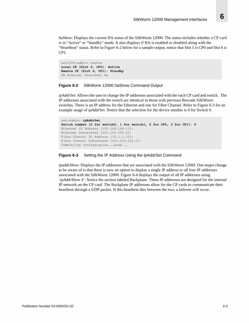
SilkWorm 12000 Management Interfaces 6
haShow: Displays the current HA status of the SilkWorm 12000. The status includes whether a CP card is in “Active” or “Standby” mode. It also displays if HA is enabled or disabled along with the “Heartbeat” status. Refer to Figure 6-2 below for a sample output, notice that Slot 5 is CP0 and Slot 6 is CP1.
Figure 6-2 SilkWorm 12000 haShow Command Output
ipAddrSet: Allows the user to change the IP addresses associated with the each CP card and switch. The IP addresses associated with the switch are identical to those with previous Brocade SilkWorm switches. There is an IP address for the Ethernet and one for Fibre Channel. Refer to Figure 6-3 for an example usage of ipAddrSet. Notice that the selection for the device number is 0 for Switch 0.
Figure 6-3 Setting the IP Address Using the ipAddrSet Command
ipaddrShow: Displays the IP addresses that are associated with the SilkWorm 12000. One major change to be aware of is that there is now an option to display a single IP address or all four IP addresses associated with the SilkWorm 12000. Figure 6-4 displays the output of all IP addresses using ‘ipAddrShow 4’. Notice the section labeled Backplane. These IP addresses are designed for the internal IP network on the CP card. The Backplane IP addresses allow for the CP cards to communicate their heartbeat through a UDP packet. If this heartbeat dies between the two, a failover will occur.
sw12000:admin> hashowLocal CP (Slot 5, CP0): ActiveRemote CP (Slot 6, CP1): StandbyHA Enabled, Heartbeat Up
sw0:admin> ipAddrSetSwitch number [0 for switch0, 1 for switch1, 2 for CP0, 3 for CP1]: 0Ethernet IP Address [192.168.149.13]: Ethernet Subnetmask [255.255.255.0]: Fibre Channel IP Address [10.1.1.10]: Fibre Channel Subnetmask [255.255.255.0]:Committing configuration...Done...
Publication Number 53-0000251-02 6-3
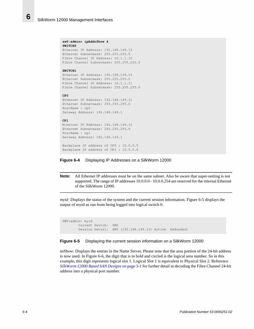
SilkWorm 12000 Management Interfaces6
Figure 6-4 Displaying IP Addresses on a SilkWorm 12000
Note: All Ethernet IP addresses must be on the same subnet. Also be aware that super-netting is not supported. The range of IP addresses 10.0.0.0 - 10.0.0.254 are reserved for the internal Ethernet of the SilkWorm 12000.
myid: Displays the status of the system and the current session information. Figure 6-5 displays the output of myid as run from being logged into logical switch 0.
Figure 6-5 Displaying the current session information on a SilkWorm 12000
nsShow: Displays the entries in the Name Server. Please note that the area portion of the 24-bit address is now used. In Figure 6-6, the digit that is in bold and circled is the logical area number. So in this example, this digit represents logical slot 1. Logical Slot 1 is equivalent to Physical Slot 2. Reference SilkWorm 12000 Based SAN Designs on page 3-1 for further detail in decoding the Fibre Channel 24-bit address into a physical port number.
sw0:admin> ipAddrShow 4SWITCH0Ethernet IP Address: 192.168.149.13Ethernet Subnetmask: 255.255.255.0Fibre Channel IP Address: 10.1.1.10Fibre Channel Subnetmask: 255.255.255.0
SWITCH1Ethernet IP Address: 192.168.149.14Ethernet Subnetmask: 255.255.255.0Fibre Channel IP Address: 10.1.1.11Fibre Channel Subnetmask: 255.255.255.0
CP0Ethernet IP Address: 192.168.149.11Ethernet Subnetmask: 255.255.255.0HostName : cp0Gateway Address: 192.168.149.1
CP1Ethernet IP Address: 192.168.149.12Ethernet Subnetmask: 255.255.255.0HostName : cp1Gateway Address: 192.168.149.1
Backplane IP address of CP0 : 10.0.0.5Backplane IP address of CP1 : 10.0.0.6
SW0:admin> myid Current Switch: SW0 Session Detail: SW0 (192.168.149.13) Active Redundant
6-4 Publication Number 53-0000251-02
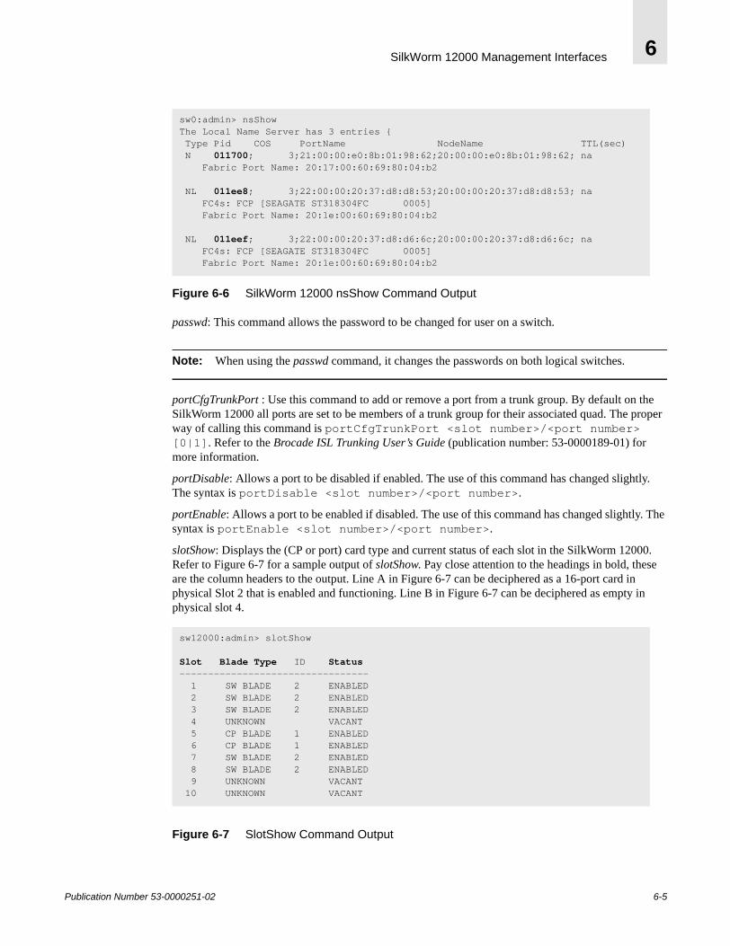
SilkWorm 12000 Management Interfaces 6
Figure 6-6 SilkWorm 12000 nsShow Command Output
passwd: This command allows the password to be changed for user on a switch.
Note: When using the passwd command, it changes the passwords on both logical switches.
portCfgTrunkPort : Use this command to add or remove a port from a trunk group. By default on the SilkWorm 12000 all ports are set to be members of a trunk group for their associated quad. The proper way of calling this command is portCfgTrunkPort <slot number>/<port number> [0|1]. Refer to the Brocade ISL Trunking User’s Guide (publication number: 53-0000189-01) for more information.
portDisable: Allows a port to be disabled if enabled. The use of this command has changed slightly. The syntax is portDisable <slot number>/<port number>.
portEnable: Allows a port to be enabled if disabled. The use of this command has changed slightly. The syntax is portEnable <slot number>/<port number>.
slotShow: Displays the (CP or port) card type and current status of each slot in the SilkWorm 12000. Refer to Figure 6-7 for a sample output of slotShow. Pay close attention to the headings in bold, these are the column headers to the output. Line A in Figure 6-7 can be deciphered as a 16-port card in physical Slot 2 that is enabled and functioning. Line B in Figure 6-7 can be deciphered as empty in physical slot 4.
Figure 6-7 SlotShow Command Output
sw0:admin> nsShowThe Local Name Server has 3 entries { Type Pid COS PortName NodeName TTL(sec) N 011700; 3;21:00:00:e0:8b:01:98:62;20:00:00:e0:8b:01:98:62; na Fabric Port Name: 20:17:00:60:69:80:04:b2
NL 011ee8; 3;22:00:00:20:37:d8:d8:53;20:00:00:20:37:d8:d8:53; na FC4s: FCP [SEAGATE ST318304FC 0005] Fabric Port Name: 20:1e:00:60:69:80:04:b2
NL 011eef; 3;22:00:00:20:37:d8:d6:6c;20:00:00:20:37:d8:d6:6c; na FC4s: FCP [SEAGATE ST318304FC 0005] Fabric Port Name: 20:1e:00:60:69:80:04:b2
sw12000:admin> slotShow
Slot Blade Type ID Status --------------------------------- 1 SW BLADE 2 ENABLED 2 SW BLADE 2 ENABLED 3 SW BLADE 2 ENABLED 4 UNKNOWN VACANT 5 CP BLADE 1 ENABLED 6 CP BLADE 1 ENABLED 7 SW BLADE 2 ENABLED 8 SW BLADE 2 ENABLED 9 UNKNOWN VACANT 10 UNKNOWN VACANT
Publication Number 53-0000251-02 6-5
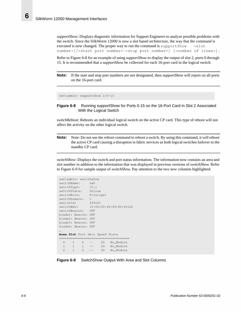
SilkWorm 12000 Management Interfaces6
supportShow: Displays diagnostic information for Support Engineers to analyze possible problems with the switch. Since the SilkWorm 12000 is now a slot based architecture, the way that the command is executed is now changed. The proper way to run the command is supportShow <slot number>[/<start port number>-<stop port number>] [<number of lines>].
Refer to Figure 6-8 for an example of using supportShow to display the output of slot 2, ports 0 through 15. It is recommended that a supportShow be collected for each 16-port card in the logical switch.
Note: If the start and stop port numbers are not designated, then supportShow will report on all ports on the 16-port card.
Figure 6-8 Running supportShow for Ports 0-15 on the 16-Port Card in Slot 2 Associated With the Logical Switch
switchReboot: Reboots an individual logical switch on the active CP card. This type of reboot will not affect the activity on the other logical switch.
Note: Note: Do not use the reboot command to reboot a switch. By using this command, it will reboot the active CP card causing a disruption in fabric services as both logical switches failover to the standby CP card.
switchShow: Displays the switch and port status information. The information now contains an area and slot number in addition to the information that was displayed in previous versions of switchShow. Refer to Figure 6-9 for sample output of switchShow. Pay attention to the two new columns highlighted.
Figure 6-9 SwitchShow Output With Area and Slot Columns
sw0:admin> supportShow 2/0-15
sw0:admin> switchshowswitchName: sw0switchType: 10.1switchState: Online switchRole: PrincipalswitchDomain: 1switchId: fffc01switchWwn: 10:00:00:60:69:80:04:b2switchBeacon: OFFblade1: Beacon: OFFblade2: Beacon: OFFblade3: Beacon: OFFblade4: Beacon: OFF_Area Slot Port Gbic Speed State ===================================== 0 1 0 -- 2G No_Module 1 1 1 -- 2G No_Module 2 1 2 -- 2G No_Module
6-6 Publication Number 53-0000251-02
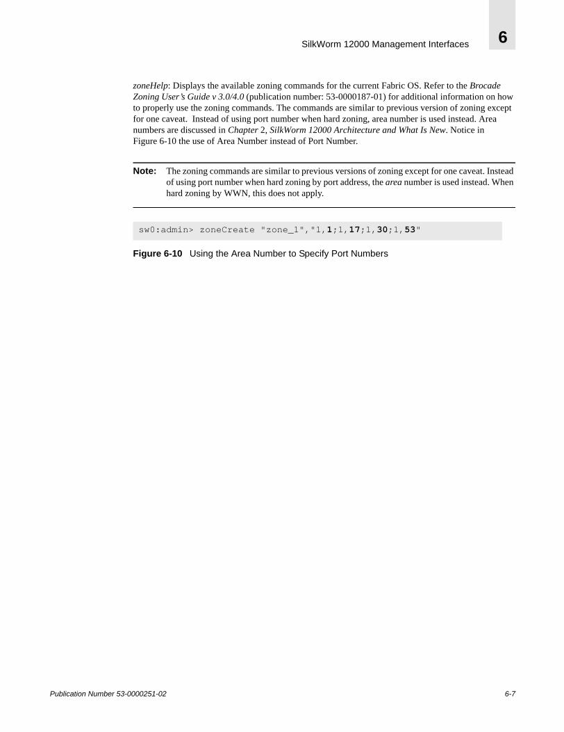
SilkWorm 12000 Management Interfaces 6
zoneHelp: Displays the available zoning commands for the current Fabric OS. Refer to the Brocade Zoning User’s Guide v 3.0/4.0 (publication number: 53-0000187-01) for additional information on how to properly use the zoning commands. The commands are similar to previous version of zoning except for one caveat. Instead of using port number when hard zoning, area number is used instead. Area numbers are discussed in Chapter 2, SilkWorm 12000 Architecture and What Is New. Notice in Figure 6-10 the use of Area Number instead of Port Number.
Note: The zoning commands are similar to previous versions of zoning except for one caveat. Instead of using port number when hard zoning by port address, the area number is used instead. When hard zoning by WWN, this does not apply.
Figure 6-10 Using the Area Number to Specify Port Numbers
sw0:admin> zoneCreate "zone_1","1,1;1,17;1,30;1,53"
Publication Number 53-0000251-02 6-7
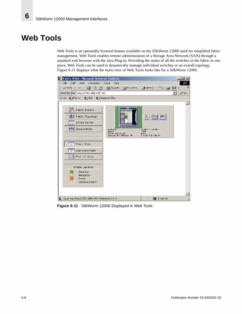
SilkWorm 12000 Management Interfaces6
Web ToolsWeb Tools is an optionally licensed feature available on the SilkWorm 12000 used for simplified fabric management. Web Tools enables remote administration of a Storage Area Network (SAN) through a standard web browser with the Java Plug-in. Providing the status of all the switches in the fabric in one place, Web Tools can be used to dynamically manage individual switches or an overall topology. Figure 6-11 displays what the main view of Web Tools looks like for a SilkWorm 12000.
Figure 6-11 SilkWorm 12000 Displayed in Web Tools
6-8 Publication Number 53-0000251-02
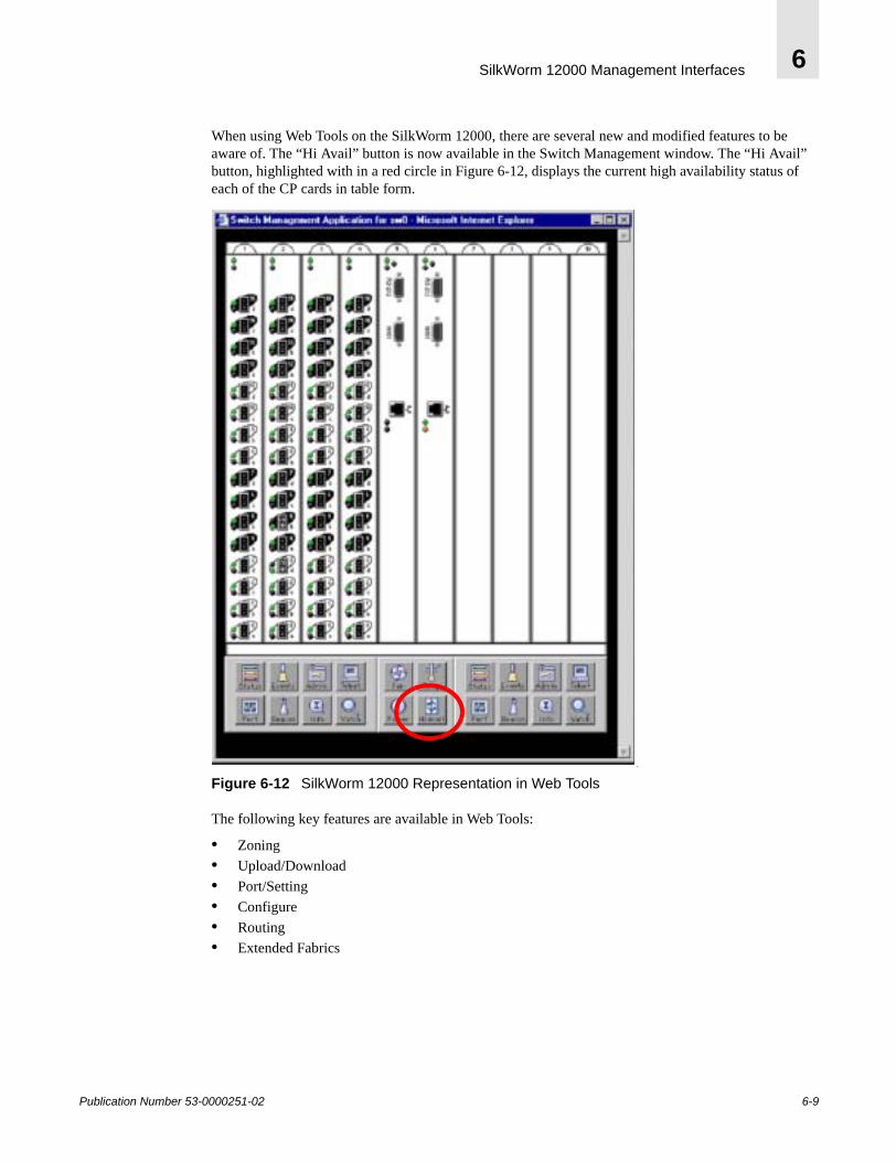
SilkWorm 12000 Management Interfaces 6
When using Web Tools on the SilkWorm 12000, there are several new and modified features to be aware of. The “Hi Avail” button is now available in the Switch Management window. The “Hi Avail” button, highlighted with in a red circle in Figure 6-12, displays the current high availability status of each of the CP cards in table form.
o
Figure 6-12 SilkWorm 12000 Representation in Web Tools
The following key features are available in Web Tools:
• Zoning• Upload/Download• Port/Setting• Configure• Routing• Extended Fabrics
Publication Number 53-0000251-02 6-9
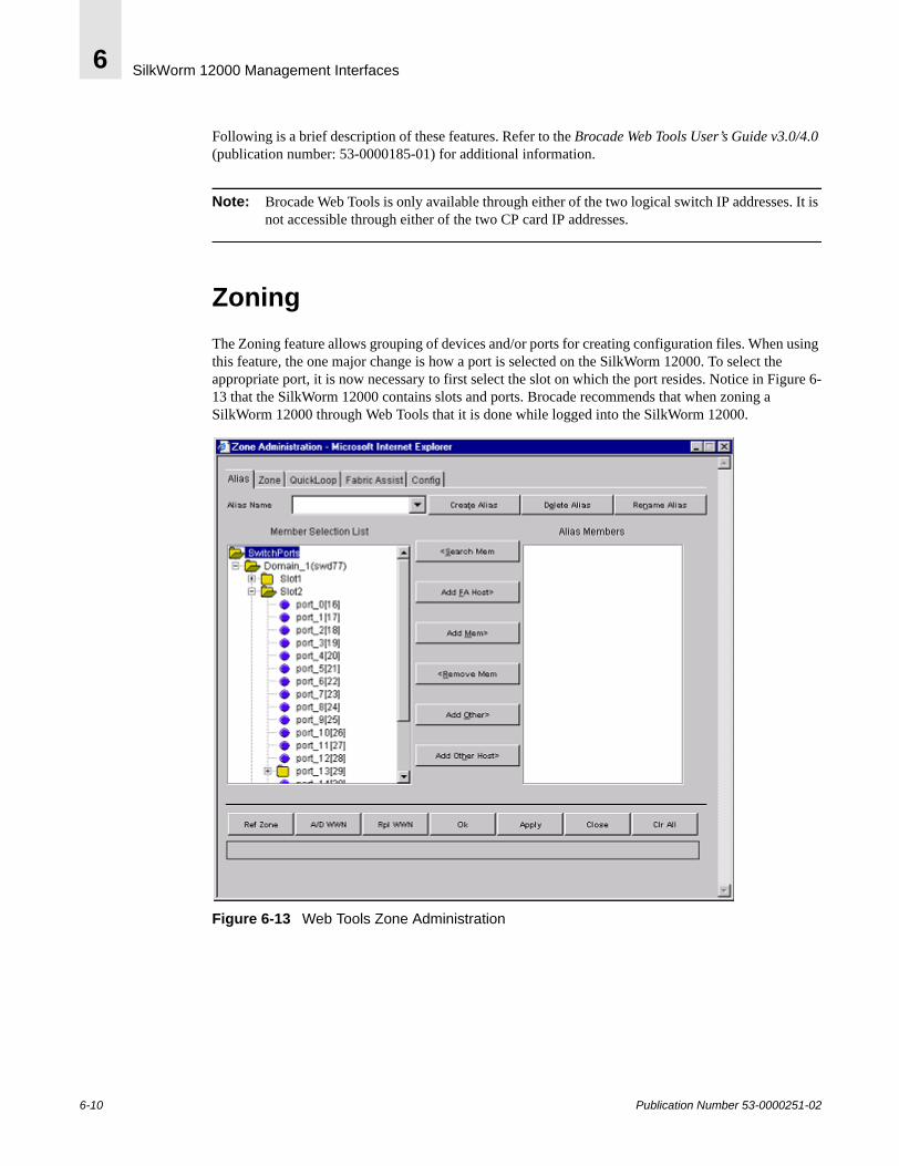
SilkWorm 12000 Management Interfaces6
Following is a brief description of these features. Refer to the Brocade Web Tools User’s Guide v3.0/4.0 (publication number: 53-0000185-01) for additional information.
Note: Brocade Web Tools is only available through either of the two logical switch IP addresses. It is not accessible through either of the two CP card IP addresses.
ZoningThe Zoning feature allows grouping of devices and/or ports for creating configuration files. When using this feature, the one major change is how a port is selected on the SilkWorm 12000. To select the appropriate port, it is now necessary to first select the slot on which the port resides. Notice in Figure 6-13 that the SilkWorm 12000 contains slots and ports. Brocade recommends that when zoning a SilkWorm 12000 through Web Tools that it is done while logged into the SilkWorm 12000.
Figure 6-13 Web Tools Zone Administration
6-10 Publication Number 53-0000251-02
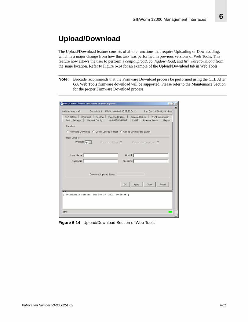
SilkWorm 12000 Management Interfaces 6
Upload/DownloadThe Upload/Download feature consists of all the functions that require Uploading or Downloading, which is a major change from how this task was performed in previous versions of Web Tools. This feature now allows the user to perform a configupload, configdownload, and firmwaredownload from the same location. Refer to Figure 6-14 for an example of the Upload/Download tab in Web Tools.
Note: Brocade recommends that the Firmware Download process be performed using the CLI. After GA Web Tools firmware download will be supported. Please refer to the Maintenance Section for the proper Firmware Download process.
Figure 6-14 Upload/Download Section of Web Tools
Publication Number 53-0000251-02 6-11
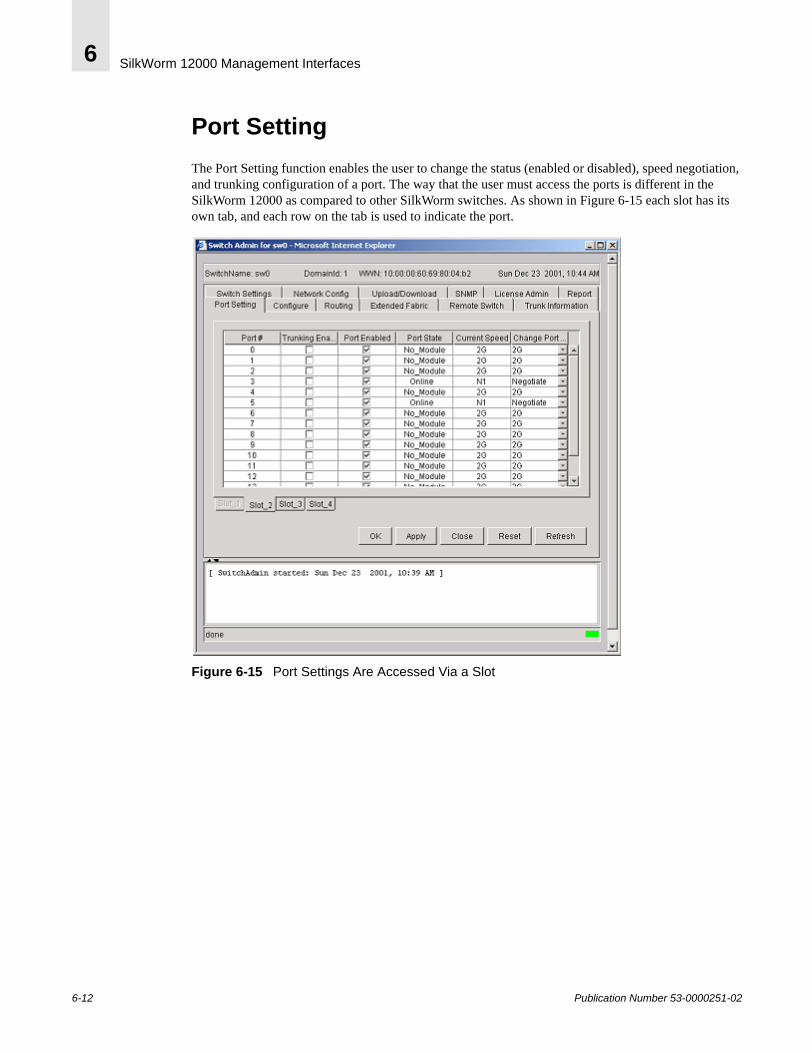
SilkWorm 12000 Management Interfaces6
Port SettingThe Port Setting function enables the user to change the status (enabled or disabled), speed negotiation, and trunking configuration of a port. The way that the user must access the ports is different in the SilkWorm 12000 as compared to other SilkWorm switches. As shown in Figure 6-15 each slot has its own tab, and each row on the tab is used to indicate the port.
Figure 6-15 Port Settings Are Accessed Via a Slot
6-12 Publication Number 53-0000251-02
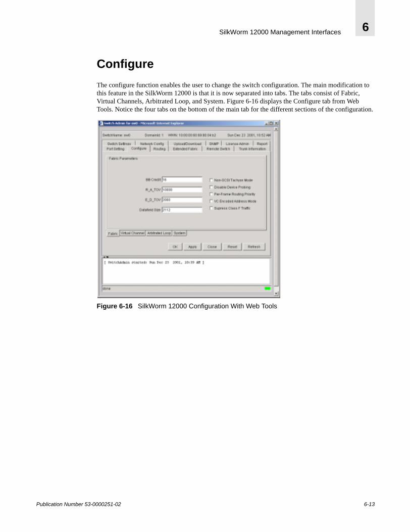
SilkWorm 12000 Management Interfaces 6
ConfigureThe configure function enables the user to change the switch configuration. The main modification to this feature in the SilkWorm 12000 is that it is now separated into tabs. The tabs consist of Fabric, Virtual Channels, Arbitrated Loop, and System. Figure 6-16 displays the Configure tab from Web Tools. Notice the four tabs on the bottom of the main tab for the different sections of the configuration.
Figure 6-16 SilkWorm 12000 Configuration With Web Tools
Publication Number 53-0000251-02 6-13
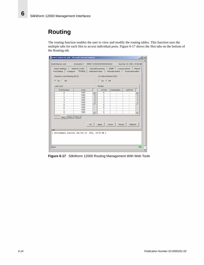
SilkWorm 12000 Management Interfaces6
RoutingThe routing function enables the user to view and modify the routing tables. This function uses the multiple tabs for each Slot to access individual ports. Figure 6-17 shows the Slot tabs on the bottom of the Routing tab.
Figure 6-17 SilkWorm 12000 Routing Management With Web Tools
6-14 Publication Number 53-0000251-02
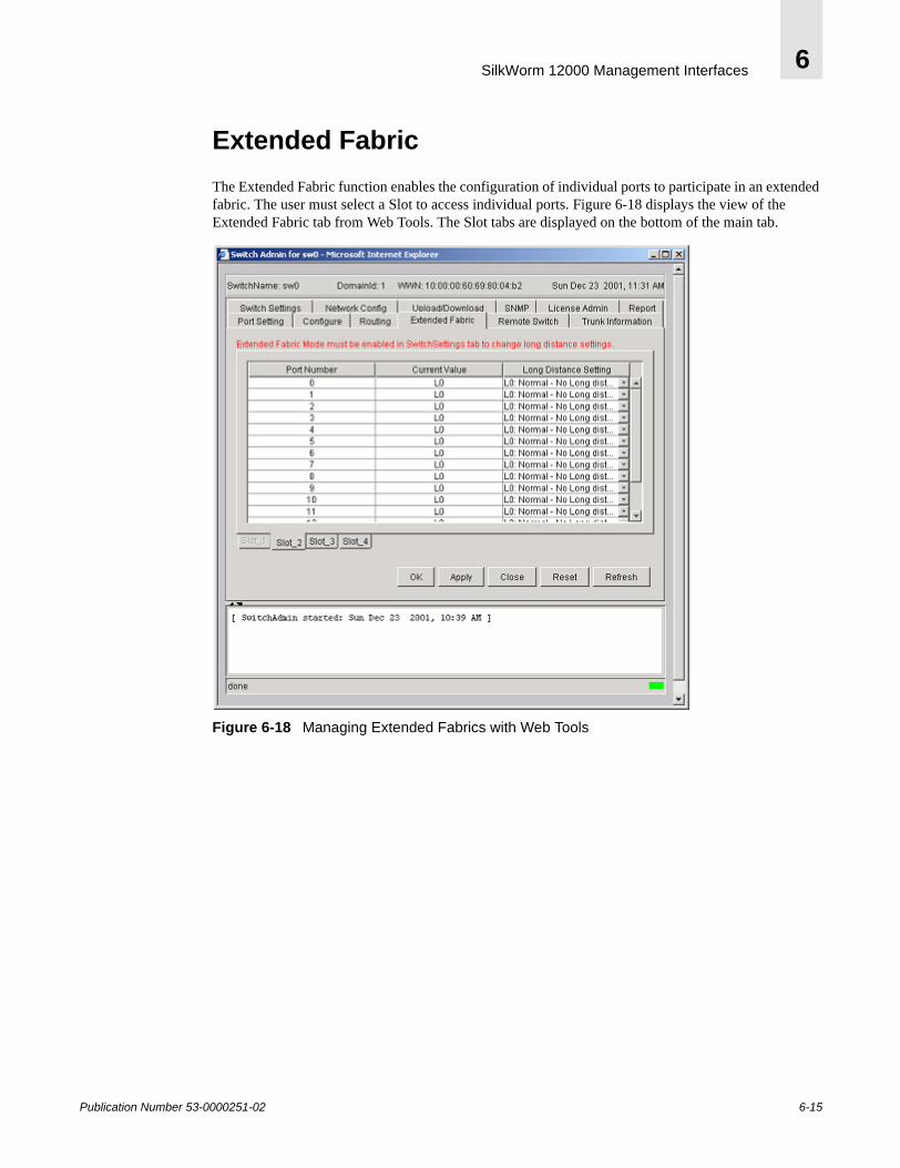
SilkWorm 12000 Management Interfaces 6
Extended FabricThe Extended Fabric function enables the configuration of individual ports to participate in an extended fabric. The user must select a Slot to access individual ports. Figure 6-18 displays the view of the Extended Fabric tab from Web Tools. The Slot tabs are displayed on the bottom of the main tab.
Figure 6-18 Managing Extended Fabrics with Web Tools
Publication Number 53-0000251-02 6-15
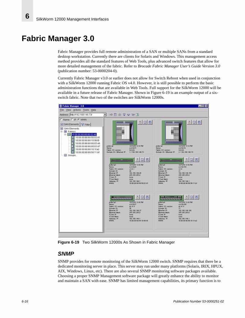
SilkWorm 12000 Management Interfaces6
Fabric Manager 3.0Fabric Manager provides full remote administration of a SAN or multiple SANs from a standard desktop workstation. Currently there are clients for Solaris and Windows. This management access method provides all the standard features of Web Tools, plus advanced switch features that allow for more detailed management of the fabric. Refer to Brocade Fabric Manager User’s Guide Version 3.0 (publication number: 53-0000204-0).
Currently Fabric Manager v3.0 or earlier does not allow for Switch Reboot when used in conjunction with a SilkWorm 12000 running Fabric OS v4.0. However, it is still possible to perform the basic administration functions that are available in Web Tools. Full support for the SilkWorm 12000 will be available in a future release of Fabric Manager. Shown in Figure 6-19 is an example output of a six-switch fabric. Note that two of the switches are SilkWorm 12000s.
Figure 6-19 Two SilkWorm 12000s As Shown in Fabric Manager
SNMPSNMP provides for remote monitoring of the SilkWorm 12000 switch. SNMP requires that there be a dedicated monitoring server in place. This server may run under many platforms (Solaris, IRIX, HPUX, AIX, Windows, Linux, etc). There are also several SNMP monitoring software packages available. Choosing a proper SNMP Management software package will greatly enhance the ability to monitor and maintain a SAN with ease. SNMP has limited management capabilities, its primary function is to
6-16 Publication Number 53-0000251-02
SilkWorm 12000 Management Interfaces 6
monitor the errors that occur in the SAN. SNMP MIBS, specifically the TRAP MIB is closely tied to Fabric Watch to get the full benefits of remote monitoring of these errors in the SAN. Please refer to the Fabric Watch 4.0 documentation for more information regarding other areas that can be monitored in addition to the SNMP features.
Within Fabric OS 4.0, there are several new components and features. The Fabric OS V4.0 version of SNMP now supports SNMP v3 and it has an extensible SNMP agent. With implementation into Fabric OS v4.0, it has all the features available in the 3.0 MIB with the addition of environmental sensors that compliment the multi-slot chassis of the SilkWorm 12000. The current sensors table has been modified to support the chassis based sensors. These sensors include 16-port card temperature as members of the switch, blower RPM sensors as part of the chassis, and power supply status as part of the chassis. Table 6-1 lists the OID for the Sensor Table. To obtain additional information regarding SNMP Management, please refer to Brocade MIB Reference Version 3.0/4.0 (publication number: 53-0000184-01).
ConsoleFor direct attach management and monitoring of the SilkWorm 12000, there is the Console. The console is a standard RS-232 serial connection wired as DCE (data communications equipment) on each of the CP cards in the SilkWorm 12000. The port can be connected to a DTE (data terminal equipment) device by use of a serial cable. Using the Console is one of the most secure ways of communicating with the switch since it is in a point-to-point communication with console terminal. The CP card has one RS-232 port and one serial port. The top port (RS-232) is for future management/monitoring expansion using a modem. The bottom port is the console port. All functionality of the console is the same as the telnet interface when connecting to the active CP card. However, the user will encounter a reduced functionality shell when connecting to the standby CP card.
Note: The SilkWorm 12000 user is strongly encouraged to manage the SilkWorm 12000 using available management methods via the logical switch and to only access the CP card via a serial connection for maintenance or diagnostic purposes.
Note: To use any of the available management methods a valid TCP/IP network connection will be required for the Ethernet port.
Table 6-1 SilkWorm 12000 OID Sensor Table
OID Output
.1.3.6.1.4.1.1588.2.1.1.1.1.22 Sensor Table
Publication Number 53-0000251-02 6-17

SilkWorm 12000 Management Interfaces6
6-18 Publication Number 53-0000251-02
Publication Number 53-0000251-02
7
Maintaining the SilkWorm 12000This chapter includes the following sections:
• Hardware Maintenance on page 7-6• Software Maintenance on page 7-23
The Hardware section describes how to identify, replace, and verify Field Replaceable Unit (FRU) components. The Software maintenance section covers how to upgrade firmware and add licenses. Figure 7-1 shows the 16-port card, CP card, and power supply on the cable side of the SilkWorm 12000. Figure 7-2 shows the blower assemblies and the WWN bezel on the non-cable side of the SilkWorm 12000.
7-1
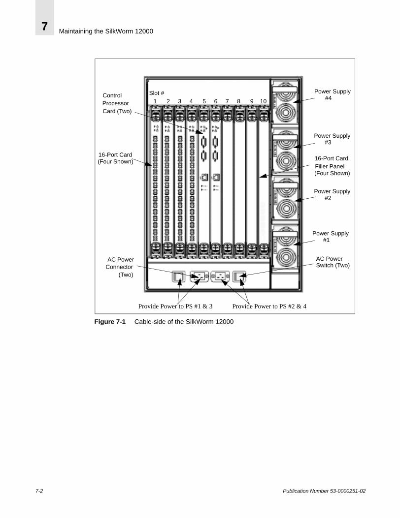
Maintaining the SilkWorm 120007
Figure 7-1 Cable-side of the SilkWorm 12000
Power Supply#4
(Two)
16-Port Card 16-Port Card
AC Power AC Power
(Four Shown)
(Four Shown)
Filler Panel
Slot # 1 2 3 4 5 6 7 8 9 10
Connector(Two)
Switch (Two)
Provide Power to PS #2 & 4 Provide Power to PS #1 & 3
Control
CardProcessor
Power Supply#3
Power Supply#2
Power Supply#1
7-2 Publication Number 53-0000251-02
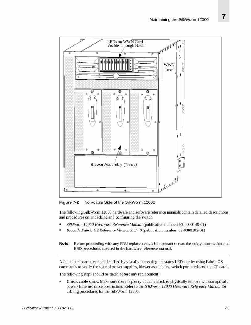
Maintaining the SilkWorm 12000 7
Figure 7-2 Non-cable Side of the SilkWorm 12000
The following SilkWorm 12000 hardware and software reference manuals contain detailed descriptions and procedures on unpacking and configuring the switch:
• SilkWorm 12000 Hardware Reference Manual (publication number: 53-0000148-01)• Brocade Fabric OS Reference Version 3.0/4.0 (publication number: 53-0000182-01)
Note: Before proceeding with any FRU replacement, it is important to read the safety information and ESD procedures covered in the hardware reference manual.
A failed component can be identified by visually inspecting the status LEDs, or by using Fabric OS commands to verify the state of power supplies, blower assemblies, switch port cards and the CP cards.
The following steps should be taken before any replacement:
• Check cable slack: Make sure there is plenty of cable slack to physically remove without optical / power/ Ethernet cable obstruction. Refer to the SilkWorm 12000 Hardware Reference Manual for cabling procedures for the SilkWorm 12000.
WWNBezel
Blower Assembly (Three)
LEDs on WWN Card Visible Through Bezel
Publication Number 53-0000251-02 7-3

Maintaining the SilkWorm 120007
• Establish a telnet/console session: Before replacing a FRU, establish a telnet or Console connection to determine a failure and verify its operation after replacement.
• Valid spare part: Make sure that the part numbers match for the unit being replaced. For example, a power supply for a SilkWorm 3800 will not work in a SilkWorm 12000. The Fabric OS v4.0 command chassisShow displays the FRU part number and Brocade serial number and additional status information. The output from the chassisShow command is displayed in Figure 7-3. The output shows 16-port cards, CP cards, power supply unit, blower assembly, and WWN information. The ‘Power Consume Factor’ is positive for producers such as the power supplies and negative for consumers such as switch and CP cards and blower assemblies. The ‘Time Alive’ is for the total time the unit has been up and the ‘Time Awake’ is the uptime from the last reboot.
7-4 Publication Number 53-0000251-02

Maintaining the SilkWorm 12000 7
Figure 7-3 chassisShow Command Output
sw0_155:admin> chassisShow_SW BLADE Slot: 1Header Version: 2Power Consume Factor: -180Brocade Part Num: 60-0001532-04Brocade Serial Num: FQ000000986Manufacture: Day: 21 Month: 5 Year: 2002Update: Day: 30 Month: 12 Year: 2001Time Alive: 14 daysTime Awake: 2 days…..CP BLADE Slot: 5Header Version: 2Power Consume Factor: -40Brocade Part Num: 60-0001604-03Brocade Serial Num: FP00X600456Manufacture: Day: 20 Month: 11 Year: 2001Update: Day: 30 Month: 12 Year: 2001Time Alive: 5 daysTime Awake: 2 days…..POWER SUPPLY Unit: 1Header Version: 2Power Consume Factor: 1000Brocade Part Num: 23-0000006-01Brocade Serial Num: D0130000885Manufacture: Day: 21 Month: 11 Year: 2001Update: Day: 30 Month: 12 Year: 2001Time Alive: 13 daysTime Awake: 2 days….FAN Unit: 1Header Version: 2Power Consume Factor: -50Brocade Part Num: 60-0001536-03Brocade Serial Num: FM3E0000283Manufacture: Day: 27 Month: 9 Year: 2001Update: Day: 30 Month: 12 Year: 2001Time Alive: 10 daysTime Awake: 1 days…WWN Unit: 1Header Version: 2Power Consume Factor: -3Brocade Part Num: 40-0000031-03Brocade Serial Num: FS000000347Manufacture: Day: 21 Month: 11 Year: 2001Update: Day: 30 Month: 12 Year: 2001Time Alive: 13 daysTime Awake: 2 days..
Publication Number 53-0000251-02 7-5

Maintaining the SilkWorm 120007
Hardware MaintenanceThe Fabric OS environmental commands chassisShow, psShow, sensorShow, and slotShow display the Brocade part numbers, 16-port card, and CP card location and its status. Brocade has optionally licensed software called Fabric Watch to monitor the system environment. This software can be used to set threshold values to pro-actively monitor environmental parameters such as temperature, fan speed and voltage. When there is a change in threshold boundaries the user can be notified via error log, SNMP trap, and email. Refer to the Fabric Watch documentation for additional details.
The Fabric OS errShow command can be used to list the status of marginal/failed components. The following is a brief summary of Fabric OS command to check the status of FRUs. These following commands are useful during replacement and verification:
psShow – display the current status of the power supplies
sw0_155:admin> psShowPower Supply #1 is OKPower Supply #2 is OKPower Supply #3 is OKPower Supply #4 is OK
fanShow – display information about the blower assemblies
sw0_155:admin> fanshowFan #1 is OK, speed is 2576 RPMFan #2 is OK, speed is 2481 RPMFan #3 is OK, speed is 2481 RPM _
SensorShow – display the current temperature, power supply and fan readings from sensors. This command is per logical switch.
sw0_155:admin> sensorShowsensor 1: (Temperature) is Ok, value is 36 Csensor 2: (Temperature) is Ok, value is 35 Csensor 3: (Temperature) is Absentsensor 4: (Temperature) is Absentsensor 5: (Temperature) is Ok, value is 21 Csensor 6: (Temperature) is Ok, value is 21 Csensor 7: (Fan ) is Ok, speed is 2576 RPMsensor 8: (Fan ) is Ok, speed is 2481 RPMsensor 9: (Fan ) is Ok, speed is 2463 RPMsensor 10: (Power Supply ) is Oksensor 11: (Power Supply ) is Faultysensor 12: (Power Supply ) is Oksensor 13: (Power Supply ) is Faulty
errShow – displays the switch error log. The following shows that the Switch 0 blower assembly has failed.
sw0_155:admin> errshowError 15--------0x2e3 (fabos): Dec 29 15:57:34 Switch: 0, Error FW-BELOW1, 3, envFan001 (Env Fan 1) is below low boundary. current value : 0 RPM. (faulty)
7-6 Publication Number 53-0000251-02
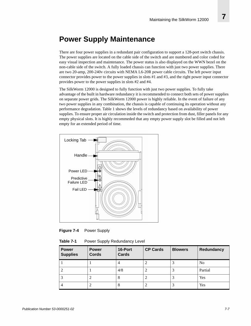
Maintaining the SilkWorm 12000 7
Power Supply MaintenanceThere are four power supplies in a redundant pair configuration to support a 128-port switch chassis. The power supplies are located on the cable side of the switch and are numbered and color coded for easy visual inspection and maintenance. The power status is also displayed on the WWN bezel on the non-cable side of the switch. A fully loaded chassis can function with just two power supplies. There are two 20-amp, 200-240v circuits with NEMA L6-20R power cable circuits. The left power input connector provides power to the power supplies in slots #1 and #3, and the right power input connector provides power to the power supplies in slots #2 and #4.
The SilkWorm 12000 is designed to fully function with just two power supplies. To fully take advantage of the built in hardware redundancy it is recommended to connect both sets of power supplies on separate power grids. The SilkWorm 12000 power is highly reliable. In the event of failure of any two power supplies in any combination, the chassis is capable of continuing its operation without any performance degradation. Table 1 shows the levels of redundancy based on availability of power supplies. To ensure proper air circulation inside the switch and protection from dust, filler panels for any empty physical slots. It is highly recommeded that any empty power supply slot be filled and not left empty for an extended period of time.
Figure 7-4 Power Supply
Table 7-1 Power Supply Redundancy Level
Power Supplies
Power Cords
16-Port Cards
CP Cards Blowers Redundancy
1 1 4 2 3 No
2 1 4/8 2 3 Partial
3 2 8 2 3 Yes
4 2 8 2 3 Yes
Power LED
PredictiveFailure LED
Fail LED
!
Locking Tab
Handle
Publication Number 53-0000251-02 7-7
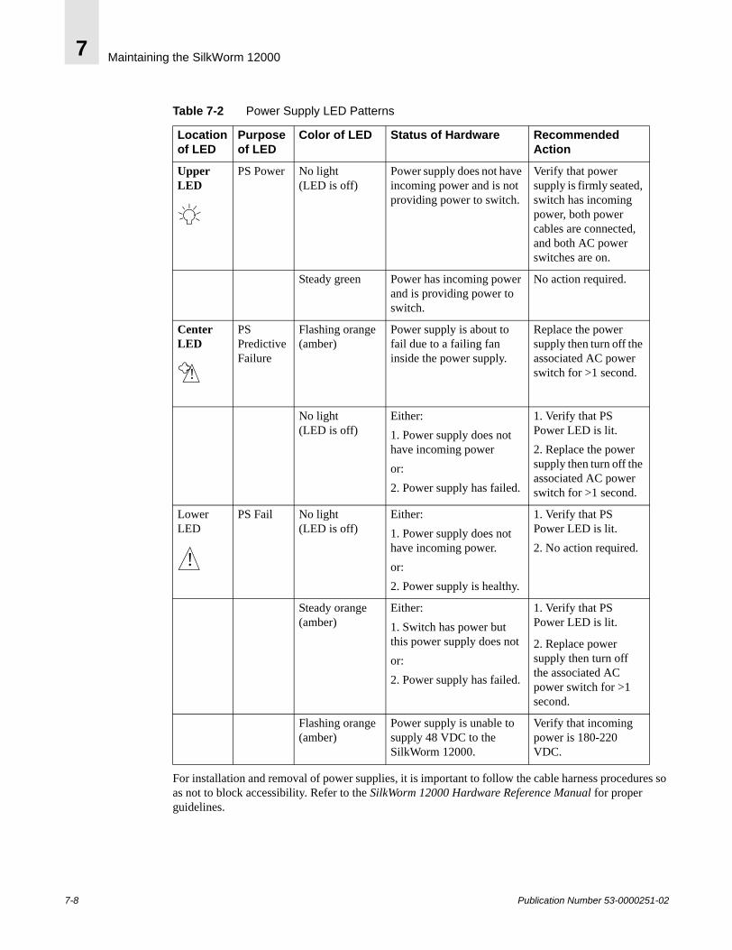
Maintaining the SilkWorm 120007
Table 7-2 Power Supply LED Patterns
For installation and removal of power supplies, it is important to follow the cable harness procedures so as not to block accessibility. Refer to the SilkWorm 12000 Hardware Reference Manual for proper guidelines.
Location of LED
Purpose of LED
Color of LED Status of Hardware Recommended Action
Upper LED
PS Power No light (LED is off)
Power supply does not have incoming power and is not providing power to switch.
Verify that power supply is firmly seated, switch has incoming power, both power cables are connected, and both AC power switches are on.
Steady green Power has incoming power and is providing power to switch.
No action required.
Center LED
PS Predictive Failure
Flashing orange (amber)
Power supply is about to fail due to a failing fan inside the power supply.
Replace the power supply then turn off the associated AC power switch for >1 second.
No light (LED is off)
Either:1. Power supply does not have incoming poweror:2. Power supply has failed.
1. Verify that PS Power LED is lit.2. Replace the power supply then turn off the associated AC power switch for >1 second.
Lower LED
PS Fail No light (LED is off)
Either:1. Power supply does not have incoming power.or:2. Power supply is healthy.
1. Verify that PS Power LED is lit.2. No action required.
Steady orange (amber)
Either:1. Switch has power but this power supply does not or:2. Power supply has failed.
1. Verify that PS Power LED is lit.
2. Replace power supply then turn off the associated AC power switch for >1 second.
Flashing orange (amber)
Power supply is unable to supply 48 VDC to the SilkWorm 12000.
Verify that incoming power is 180-220 VDC.
!
!
7-8 Publication Number 53-0000251-02

Maintaining the SilkWorm 12000 7
Identify A Faulty Power Supply To determine if a power supply is marginal or has failed:
1. Check the LED status on the power supply, or the power supply LEDs on the WWN bezel (card). Refer to Table 1 for interpretation.
2. Check status using psShow.
sw0_155:admin> psshowPower Supply #1 is OKPower Supply #2 is faultyPower Supply #3 is OKPower Supply #4 is faulty
In the example above, power supplies 2 and 4 are faulty. If there were no power supplies in the slots, they would be marked as absent. Refer to the help page for a detail description of psShow. Since circuit 2 provides power for supplies 2 and 4, verify that the circuit is cabled and powered. The power supplies can be installed and removed in a hot swap manner without executing any command line utilities.
Steps For Installation and Removal
Power supply removal1. Press on the release tab located on upper left corner.
2. Pull down the release handle.
3. Grab the release handle and pull.
Power supply installation 1. Orient the power supply so that the tab is towards the front of the switch.
2. Insert the power supply all the way into the slot and push the handle until it clicks.
3. Verify status. If the circuit is powered, a green status appears indicating it is online. Power supply status can also be gathered from the WWN bezel located on the non-cable side of the switch.
Note: Do not force the installation. If the power supply does not slide easily, ensure the unit is properly oriented before continuing with the installation.
The optimal power output for each power supply is 1000 amps. The Fabric Watch application can be used to pro-actively monitor this value and be notified of any power output changes. The following output indicates that all the power supplies are functioning optimally:
sw0_155:admin> psshowPower Supply #1 is OKPower Supply #2 is OKPower Supply #3 is OKPower Supply #4 is OK
Publication Number 53-0000251-02 7-9
Maintaining the SilkWorm 120007
Blowers MaintenanceThere are three hot swappable blower assemblies and only two are required for cooling. Air enters from the non-cable side of the chassis and exits at the top front of cable side. Three blower assemblies are used in conjunction with a pressurized plenum to cool the unit. The SilkWorm 12000 hardware is designed to withstand the loss of a single blower assembly and continue to run. Table 7-3 lists the operational efficiency based on blower assembly availability. All slots must either have a 16-port card installed or a filler panel installed for efficient cooling. Figure 7-5 shows the blower assemblies located on the non-cable side of the switch.
Each blower assembly includes a blower card assembly, which provides the following features:
• Blower status LEDs • Blower speed sensing• Blower speed control• Serial Electronically Erasable Programmable Read Only Memory (EEPROM) for blower assembly
part number, revision level, and error logs
Since the blower assemblies are located on the non-cable side of the switch, it is important to follow proper installation and cabling procedures. There should be at least a two feet of gap in front of the blower assembly for easy removal and install. Refer to the SilkWorm 12000 Hardware Reference Manual for proper switch installation guidelines.
Identify A Faulty Blower Assembly To determine if a blower assembly is marginal or faulty:
1. Check the LED status on the blower assembly. Refer to Table 7-4.
2. Check status using fanShow.
sw0_155:admin> fanshowFan #1 is absentFan #2 is OK, speed is 3013 RPMFan #3 is OK, speed is 3183 RPM
In the above example, blower assembly #1 is absent, meaning it has not been installed. If there is a blower assembly that is not functioning then it is marked as faulty. There are status LEDs on the blower assembly. A green LED indicates that power is good. An amber LED indicates that the blower assembly needs attention. When there are less than three blower assemblies operating, the fan RPM increases to compensate for the reduced airflow. The nominal RPM range is 2001-3400. Speeds above or below this range result in a warning being issued.
Table 7-3 Blower Availability
Blowers 16-port card Power down time
Operational Level
Action
3 8 N/A 100% None
2 8 N/A 100% Replace at next maintenance
1 8 N/A Less than 100% Replace within 1 hour
7-10 Publication Number 53-0000251-02
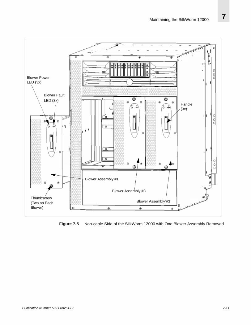
Maintaining the SilkWorm 12000 7
Figure 7-5 Non-cable Side of the SilkWorm 12000 with One Blower Assembly Removed
Blower Assembly #3
Blower FaultLED (3x)
Thumbscrew(Two on Each
Blower Assembly #1
Blower Power
Blower Assembly #3
Handle
LED (3x)
(3x)
Blower)
Publication Number 53-0000251-02 7-11

Maintaining the SilkWorm 120007
Blower Removal
Caution: Support the blower from underneath while removing it from the chassis.
1. Loosen the thumbscrews on the top and bottom of the assembly.
2. Press on the top of the blower assembly handle until the handle pops open.
3. Grab the handle and pull. The blower assembly should easily slide out.
Blower Install
Caution: Do not force the installation. If the blower assembly does not slide in easily, ensure the unit is properly oriented before continuing with the installation.
1. Line up the power plug on the blower assembly to the power socket in backplane.
2. Slide it in until it connects, and a power LED light should come on.
3. Push the top of the handle into the recess.
4. Tighten the thumbscrews to lock it in place.
Table 7-4 Blower Assembly LED Pattern
Location of LED
Purpose of LED
Color of LED
Status of Hardware Recommended Action
Left LED Blower Assembly Power
Steady green Blower assembly has incoming power.
No action required.
No light (LED is off)
Blower assembly does not have incoming power.
Verify that blower assembly is firmly seated and power supplies are on.
Right LED
Blower Assembly Status
No light (LED is off)
Either:1. Blower assembly does not have incoming power.or:2. Blower assembly is healthy.
1. Verify that Blower Assembly Power LED is lit.2. No action required.
Steady orange (amber)
Blower assembly has failed. Replace blower assembly.
7-12 Publication Number 53-0000251-02
Maintaining the SilkWorm 12000 7
Blower FRU hot plug cycles are instantaneous -- blower assemblies operate immediately upon insertion or power up. After installing the blower assembly, use the fanShow command to verify proper operation.
Running with three blower assemblies is the optimal spec for the SilkWorm 12000. The switch continues to operate if multiple blower assemblies fail. The system uses the card power down sequence defined by the powerOffListShow/powerOffListSet command to power down when temperature threshold values are exceeded. In the following example powerOffListShow 16-port card in Slot 10 would power down first and decrement as necessary.
sw0_155:admin> powerofflistshowSlot 10 will be powered off 1stSlot 9 will be powered off 2ndSlot 8 will be powered off 3rdSlot 7 will be powered off 4thSlot 4 will be powered off 5thSlot 3 will be powered off 6thSlot 2 will be powered off 7thSlot 1 will be powered off 8th
Note: The three blower assemblies for the SilkWorm 12000 are hot swappable and can be replaced without any tools. The fanShow command can be used determine and verify proper operation. A fully loaded chassis can continue to operate without disruption with just two blower assemblies.
Control Processor MaintenanceThere are two control processor (CP) cards in a SilkWorm 12000 chassis. The initial release supports an active-standby configuration where one CP card can manage two 64-port switches in the chassis. Figure 7-6 shows the CP card location in the chassis, Slots 5 and 6 are for the CP cards.
Publication Number 53-0000251-02 7-13
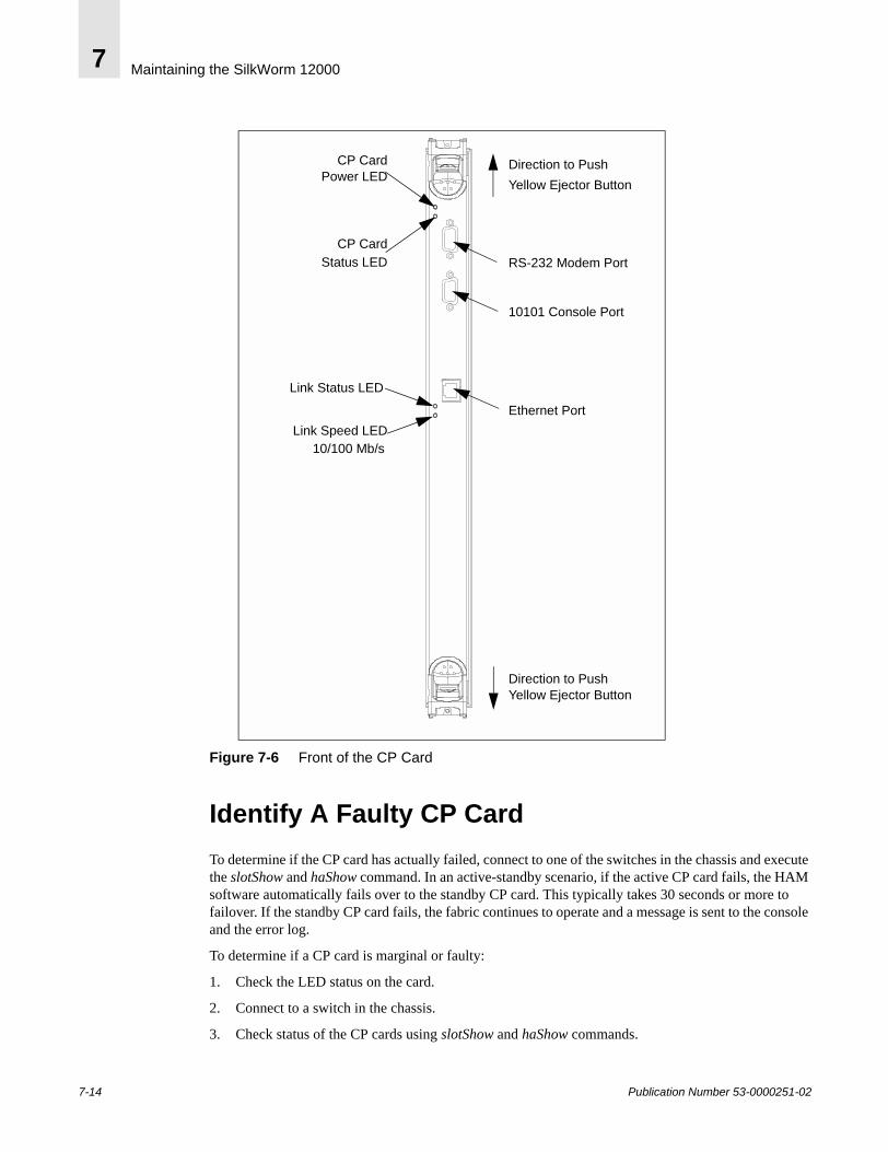
Maintaining the SilkWorm 120007
Figure 7-6 Front of the CP Card
Identify A Faulty CP Card To determine if the CP card has actually failed, connect to one of the switches in the chassis and execute the slotShow and haShow command. In an active-standby scenario, if the active CP card fails, the HAM software automatically fails over to the standby CP card. This typically takes 30 seconds or more to failover. If the standby CP card fails, the fabric continues to operate and a message is sent to the console and the error log.
To determine if a CP card is marginal or faulty:
1. Check the LED status on the card.
2. Connect to a switch in the chassis.
3. Check status of the CP cards using slotShow and haShow commands.
RS-232 Modem Port
Ethernet Port
Link Status LED
Link Speed LED
CP Card
CP Card
10101 Console Port
10/100 Mb/s
Direction to Push Yellow Ejector Button
Direction to Push Yellow Ejector ButtonPower LED
Status LED
7-14 Publication Number 53-0000251-02

Maintaining the SilkWorm 12000 7
sw0_155:admin> slotshowSlot 16-port card Type ID Status --------------------------------- 1 SW 16-PORT CARD 2 ENABLED 2 SW 16-PORT CARD 2 ENABLED 3 UNKNOWN VACANT 4 UNKNOWN VACANT 5 UNKNOWN VACANT 6 CP 16-PORT CARD 1 ENABLED 7 UNKNOWN VACANT 8 UNKNOWN VACANT 9 UNKNOWN VACANT 10 UNKNOWN VACANTsw0_155:admin> haShowLocal CP (Slot 6, CP1): ActiveRemote CP (Slot 5, CP0): Non-Redundant
In the above example, slotShow slot 5 is listed as vacant even though the card exists. This situation could be caused by two things: the CP card is not seated properly or has failed. The output of haShow shows that the active CP card is in slot 6 and the CP card in slot 5 is listed as Non-Redundant -- meaning it is either failed, is in the process of booting, or the card is not powered on. Make sure that the CP card is installed properly and the ejector latch is locked in place.
CP Card Removal1. If the procedure is being performed on an operating switch, verify the correct functioning of the CP
Card that is not being replaced. Refer to the above section determining CP card status.
a. Verify that all cable connections are secure and the CP Card is firmly seated in the switch.
b. Verify that the LED at the top of the CP Card is displaying a steady green light.
c. Verify that the second LED from the top of the CP Card is not lit.
2. Remove the CP Card or filler panel currently in the slot.
a. If removing a CP Card, disconnect the following cables if present:
• Modem cable from the modem serial port• Serial cable from the terminal serial port• Ethernet cable from the ethernet port
b. Release both ejector latches on the CP Card or filler panel by pushing the yellow tab on each ejector in and levering the black handles open.
c. Slide the CP Card or filler panel toward you and out of the switch.
Note: Do not pull on or hold the CP card by the ejector levers. This could result in the levers breaking off from the card.
If there is no replacement CP card, the slot should be covered with filler panel to maintain optimal cooling. There is no redundancy in a single CP card configuration and the faulted CP card should be replaced immediately.
Publication Number 53-0000251-02 7-15

Maintaining the SilkWorm 120007
CP Card Installation1. Install the new CP Card or filler panel in the slot.
Caution: Do not force the installation. If the CP Card or filler panel does not slide in easily, ensure it is correctly oriented and aligned in the rail guides before continuing. Installing a CP Card or filler panel with incorrect alignment damages the chassis and the CP Card or filler panel.
a. Orient the CP Card or filler panel so that the ejectors are at the front of the switch and the flat metal side is on the left.
b. Align the flat metal side of the CP Card or filler panel inside the upper and lower rail guides in the slot, and slide the CP Card or filler panel into the slot until it is firmly seated.
c. Close the ejectors by pushing the black handles in toward the CP Card or filler panel, until the handles click. The levering action of the handles seats the CP Card or filler panel in the switch.
If a filler panel was installed, the installation procedure is now complete.
2. Additional steps if a CP Card was installed:
a. Verify that the CP Card Power LED on the CP Card is displaying a steady green light. If not, ensure the CP Card has power and is firmly seated. The front of the CP Card should be flush with the adjacent cards or filler panels, with both ejectors closed.
Note: The LEDs patterns may temporarily change during POST and other diagnostic tests.
7-16 Publication Number 53-0000251-02
Maintaining the SilkWorm 12000 7
CP Card VerificationOnce the CP card is seated properly, it automatically runs a memory test, then goes into standby mode.
After installing the CP card, use the Fabric OS commands slotShow and haShow to verify the operation. Note that in the slotShow output, the CP card in Slot 5 is listed as ENABLED. The haShow output shows that CP0 is in a standby mode and is available for failover.
sw0_155:admin> slotshowSlot 16-port card Type ID Status --------------------------------- 1 SW 16-PORT CARD 2 ENABLED 2 SW 16-PORT CARD 2 ENABLED 3 UNKNOWN VACANT 4 UNKNOWN VACANT 5 CP 16-PORT CARD 1 ENABLED 6 CP 16-PORT CARD 1 ENABLED 7 UNKNOWN VACANT 8 UNKNOWN VACANT 9 UNKNOWN VACANT 10 UNKNOWN VACANT
sw0_155:admin> haShowLocal CP (Slot 6, CP1): ActiveRemote CP (Slot 5, CP0): StandbyHA Enabled, Heartbeat Upsw0_155:admin>
Note: The two CP cards in the SilkWorm 12000 are hot swappable and operate in an active standby configuration. Before removing a faulty CP card, verify that it is NOT the active CP card.
16-Port Card MaintenanceEach 16-port card (see Figure 7-7) houses sixteen auto-sensing 1- 2 Gbit/sec Fibre Channel ports and uses SFP optical transceivers. The Fibre Channel interfaces of the SilkWorm 12000 are equipped with an optical port interface that uses a Short Wavelength (SWL), 780 to 850 nm, or Long Wavelength (LWL), 1270 to 1350 nm, laser transmitter. The SilkWorm 12000 Hardware Reference Manual (publication number: 53-0000148-01) has additional details on SFP safety compliance.
To maximize system availability when the 16-port card is plugged in, it is initially powered off by the hardware. This ensures that the addition of a 16-port card does not bring the whole switch down if inadequate power is available. The system confirms sufficient power for the new module and then applies power. If sufficient power is not available, for example, if only two of the possible four power supplies are installed, the system does not allow the 16-port card to be powered up. Normal operating range is below 78 degrees Celsius. When there is degradation in power and cooling, the 16-port cards will power down based on the powerOffListSet definitions.
Publication Number 53-0000251-02 7-17
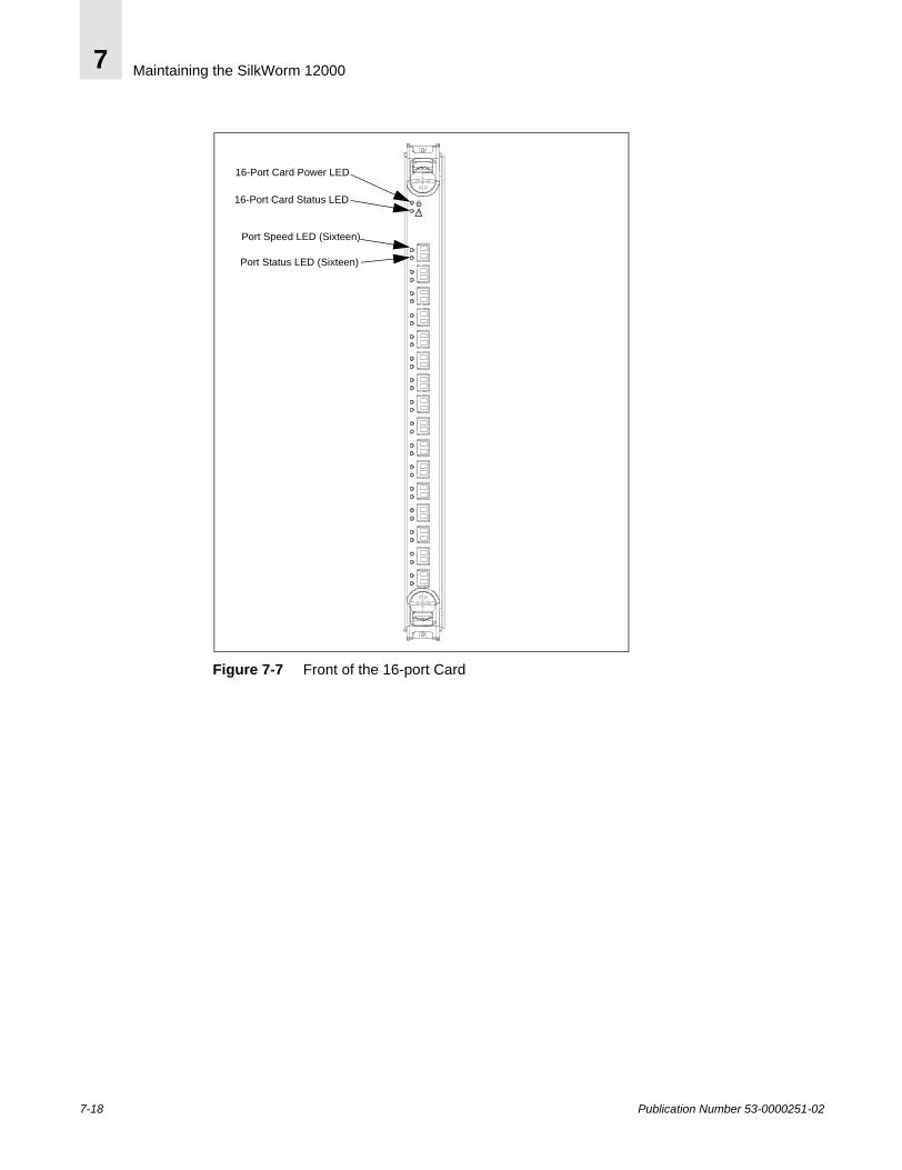
Maintaining the SilkWorm 120007
Figure 7-7 Front of the 16-port Card
16-Port Card Power LED
Port Speed LED (Sixteen)
Port Status LED (Sixteen)
16-Port Card Status LED!
7-18 Publication Number 53-0000251-02

Maintaining the SilkWorm 12000 7
Table 7-5 16-Port Card LED Pattern
Location of LED on Installed Card
Purpose of LED
Color of LED Status of Hardware Recommended Action
Top LED 16-port Card Power
Steady green 16-port card has incoming power.
No action required.
No light (LED is off)
16-port card does not have incoming power.
Verify that 16-port card is firmly seated and power supplies are on.
Second LED 16-port Card Status
No light (LED is off)
Either:1. 16-port card does not have incoming power.or:2. 16-port card is healthy; no faults detected.
1. Verify that 16-Port Card Power LED is lit.2. No action required.
Steady yellow 16-port card has a board problem.
Verify 16-port card is firmly seated. If LED is still yellow, consult your switch supplier.
Left of each port, upper LED
Port Status No light (LED is off)
Either:1. 16-port card does not have incoming power.or:2.No light or signal carrier (media or cable) detected.
1. Verify that 16-Port Card Power LED is lit.2. Check media and cable.
Steady green Port is online (connected to an external device) but has no traffic.
No action required.
Slow-flashing green (on 1 second; off 1 second)
Port is online but segmented, indicating a loop back cable or incompatible switch.
Verify correct device is connected to port.
Fast-flashing green(on 1/4 second;off 1/4 second)
Port is in internal loop back (diagnostic).
No action required.
Flickering green
Port is online, with traffic flowing through port.
No action required.
!
Publication Number 53-0000251-02 7-19

Maintaining the SilkWorm 120007
Identifying A Faulty 16-Port CardTo determine if a 16-Port Card is marginal or faulty, follow these steps:
1. Check the LED status on the card. Refer to Table 7-5.
2. Connect to a switch in the chassis with the faulty card.
3. Check status of a card using slotShow.
sw0_155:admin> slotshow_Slot Blade Type ID Status --------------------------------- 1 SW BLADE 2 ENABLED 2 SW BLADE 2 ENABLED 3 UNKNOWN VACANT 4 UNKNOWN VACANT 5 CP BLADE 1 ENABLED 6 CP BLADE 1 ENABLED 7 UNKNOWN VACANT 8 UNKNOWN VACANT 9 UNKNOWN VACANT 10 UNKNOWN VACANT
16-Port Card RemovalThere are several things to consider, before performing a card replacement, as the card removal can affect many things in the fabric. Questions to answer before doing the card replacement:
• Is there built in redundancy in the fabric design?• Are all the ports ISLs?• Are all the ports SAN devices?• Do all the connected ports contain a mixture of ISLs and edge devices?
If the 16-port card is all ISLs or a mixture of ISLs and edge devices, the fabric re-configures to establish new routes. If the 16-port card has all edge devices, then these devices will lose connection to the fabric, unless there redundant connections to the same fabric. If there is redundancy built into the fabric design I/O resumes on the new routes.
Before removing any cables from the faulty 16-port card make a note of cable order by referring a cable to the physical port. This reduces the confusion during re-cabling. Refer to the SilkWorm 12000 Hardware Reference Manual for guidelines regarding cabling procedures. If multiple cards are being replaced, replace one card at a time to prevent confusion during the cable re-connection phase. Before replacing a 16-port card determine if it is the entire card or the SFPs that are faulty.
To Remove A 16-Port Card1. If removing a 16-Port Card: Disconnect any SFP transceivers and cables from the 16-Port Card.
2. Release both ejectors on the 16-Port Card or filler panel by pushing the yellow tab on each ejector in and levering the black handles open.
3. Slide the 16-Port Card or filler panel out of the switch.
7-20 Publication Number 53-0000251-02
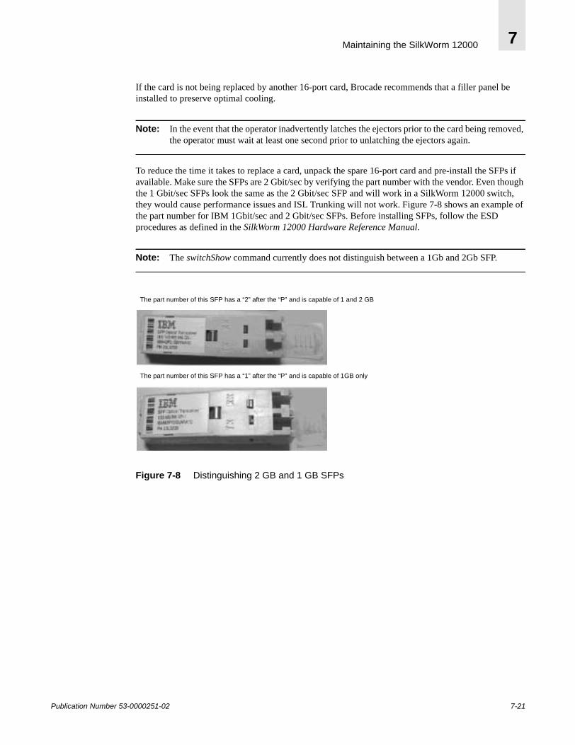
Maintaining the SilkWorm 12000 7
If the card is not being replaced by another 16-port card, Brocade recommends that a filler panel be installed to preserve optimal cooling.
Note: In the event that the operator inadvertently latches the ejectors prior to the card being removed, the operator must wait at least one second prior to unlatching the ejectors again.
To reduce the time it takes to replace a card, unpack the spare 16-port card and pre-install the SFPs if available. Make sure the SFPs are 2 Gbit/sec by verifying the part number with the vendor. Even though the 1 Gbit/sec SFPs look the same as the 2 Gbit/sec SFP and will work in a SilkWorm 12000 switch, they would cause performance issues and ISL Trunking will not work. Figure 7-8 shows an example of the part number for IBM 1Gbit/sec and 2 Gbit/sec SFPs. Before installing SFPs, follow the ESD procedures as defined in the SilkWorm 12000 Hardware Reference Manual.
Note: The switchShow command currently does not distinguish between a 1Gb and 2Gb SFP.
Figure 7-8 Distinguishing 2 GB and 1 GB SFPs
The part number of this SFP has a “2” after the “P” and is capable of 1 and 2 GB
The part number of this SFP has a “1” after the “P” and is capable of 1GB only
Publication Number 53-0000251-02 7-21

Maintaining the SilkWorm 120007
Installing A 16-Port Card
Caution: Do not force the installation. If the 16-Port Card or filler panel does not slide in easily, ensure it is correctly aligned inside the rail guides before continuing. Installing a 16-Port Card or filler panel with incorrect alignment damages both the chassis and the replacement part.
1. Orient the 16-port card or filler panel so that the ejectors are at the front of the switch and the flat side of the 16-port card or filler panel is on the left.
2. Align the flat side of the 16-port card or filler panel inside the upper and lower rail guides in the slot, and slide the 16-port card or filler panel into the slot until it is firmly seated.
3. Close the ejectors by pushing in the black handles toward the center of the 16-port card or filler panel until the handles click. The levering action of the handles seats the 16-port card or filler panel in the slot.
If a new 16-Port Card was installed, perform the following steps:
1. Verify that the top LED on the 16-port card is displaying a steady green light. If not, ensure the16-port card is firmly seated (the front of the 16-port card should be flush with adjacent 16-port cards or filler panels), both ejectors are closed, and the switch has power.
Note: The LEDs patterns may temporarily change during POST and other diagnostic tests.
2. Install SFP transceivers and cables in the new 16-port card, as required.
3. Group and route the cables as desired.
16-Port Card Verification First, verify that the CP card recognizes the 16-port card by connecting to a switch and issuing the slotShow command. To verify that a fabric has been restored to its original operational status after re-cabling, connect to each switch in the fabric and execute switchShow and nsShow. The output of these commands should match the configuration prior to the failure. The total number of ISLs, number of devices, number of switches, and domain ids should match the original database.
7-22 Publication Number 53-0000251-02
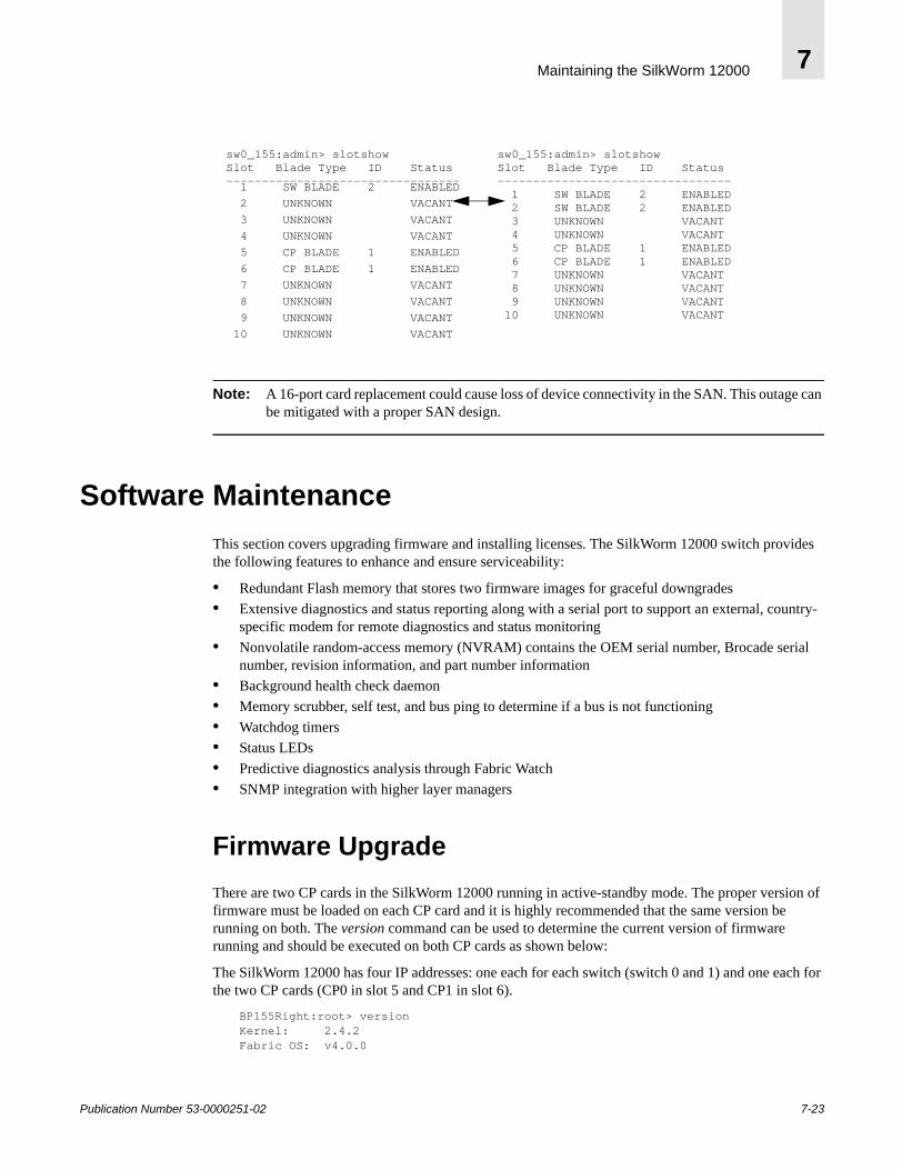
Maintaining the SilkWorm 12000 7
Note: A 16-port card replacement could cause loss of device connectivity in the SAN. This outage can be mitigated with a proper SAN design.
Software MaintenanceThis section covers upgrading firmware and installing licenses. The SilkWorm 12000 switch provides the following features to enhance and ensure serviceability:
• Redundant Flash memory that stores two firmware images for graceful downgrades• Extensive diagnostics and status reporting along with a serial port to support an external, country-
specific modem for remote diagnostics and status monitoring• Nonvolatile random-access memory (NVRAM) contains the OEM serial number, Brocade serial
number, revision information, and part number information• Background health check daemon• Memory scrubber, self test, and bus ping to determine if a bus is not functioning• Watchdog timers• Status LEDs• Predictive diagnostics analysis through Fabric Watch• SNMP integration with higher layer managers
Firmware UpgradeThere are two CP cards in the SilkWorm 12000 running in active-standby mode. The proper version of firmware must be loaded on each CP card and it is highly recommended that the same version be running on both. The version command can be used to determine the current version of firmware running and should be executed on both CP cards as shown below:
The SilkWorm 12000 has four IP addresses: one each for each switch (switch 0 and 1) and one each for the two CP cards (CP0 in slot 5 and CP1 in slot 6).
BP155Right:root> versionKernel: 2.4.2 Fabric OS: v4.0.0
sw0_155:admin> slotshow
1 SW BLADE 2 ENABLED 2 UNKNOWN VACANT 3 UNKNOWN VACANT 4 UNKNOWN VACANT 5 CP BLADE 1 ENABLED 6 CP BLADE 1 ENABLED 7 UNKNOWN VACANT 8 UNKNOWN VACANT 9 UNKNOWN VACANT 10 UNKNOWN VACANT
sw0_155:admin> slotshowSlot Blade Type ID Status--------------------------------- 1 SW BLADE 2 ENABLED 2 SW BLADE 2 ENABLED 3 UNKNOWN VACANT 4 UNKNOWN VACANT 5 CP BLADE 1 ENABLED 6 CP BLADE 1 ENABLED 7 UNKNOWN VACANT 8 UNKNOWN VACANT 9 UNKNOWN VACANT 10 UNKNOWN VACANT
Slot Blade Type ID Status---------------------------------
Publication Number 53-0000251-02 7-23
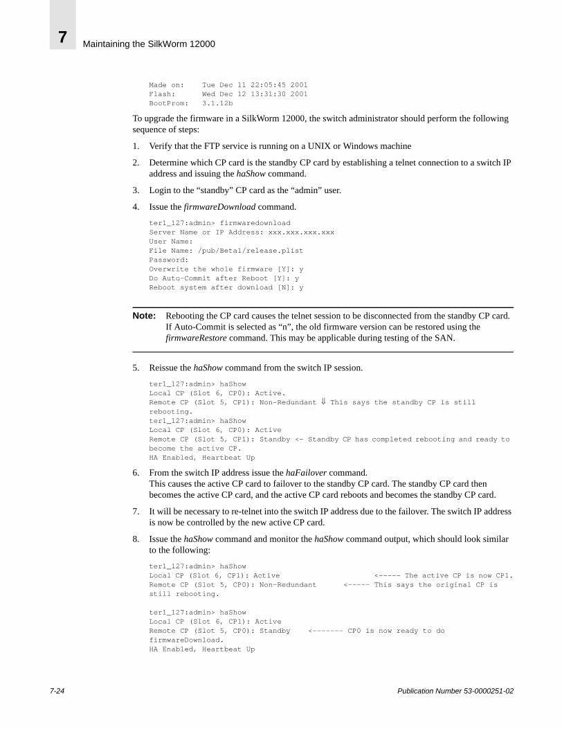
Maintaining the SilkWorm 120007
Made on: Tue Dec 11 22:05:45 2001Flash: Wed Dec 12 13:31:30 2001BootProm: 3.1.12b
To upgrade the firmware in a SilkWorm 12000, the switch administrator should perform the following sequence of steps:
1. Verify that the FTP service is running on a UNIX or Windows machine
2. Determine which CP card is the standby CP card by establishing a telnet connection to a switch IP address and issuing the haShow command.
3. Login to the “standby” CP card as the “admin” user.
4. Issue the firmwareDownload command.
ter1_127:admin> firmwaredownloadServer Name or IP Address: xxx.xxx.xxx.xxxUser Name:File Name: /pub/Beta1/release.plistPassword:Overwrite the whole firmware [Y]: y Do Auto-Commit after Reboot [Y]: y Reboot system after download [N]: y
Note: Rebooting the CP card causes the telnet session to be disconnected from the standby CP card. If Auto-Commit is selected as “n”, the old firmware version can be restored using the firmwareRestore command. This may be applicable during testing of the SAN.
5. Reissue the haShow command from the switch IP session.
ter1_127:admin> haShowLocal CP (Slot 6, CP0): Active.Remote CP (Slot 5, CP1): Non-Redundant ⇓ This says the standby CP is still rebooting.ter1_127:admin> haShowLocal CP (Slot 6, CP0): ActiveRemote CP (Slot 5, CP1): Standby <- Standby CP has completed rebooting and ready to become the active CP.HA Enabled, Heartbeat Up
6. From the switch IP address issue the haFailover command.This causes the active CP card to failover to the standby CP card. The standby CP card then becomes the active CP card, and the active CP card reboots and becomes the standby CP card.
7. It will be necessary to re-telnet into the switch IP address due to the failover. The switch IP address is now be controlled by the new active CP card.
8. Issue the haShow command and monitor the haShow command output, which should look similar to the following:
ter1_127:admin> haShowLocal CP (Slot 6, CP1): Active <----- The active CP is now CP1.Remote CP (Slot 5, CP0): Non-Redundant <----- This says the original CP is still rebooting.
ter1_127:admin> haShowLocal CP (Slot 6, CP1): ActiveRemote CP (Slot 5, CP0): Standby <------- CP0 is now ready to do firmwareDownload.HA Enabled, Heartbeat Up
7-24 Publication Number 53-0000251-02
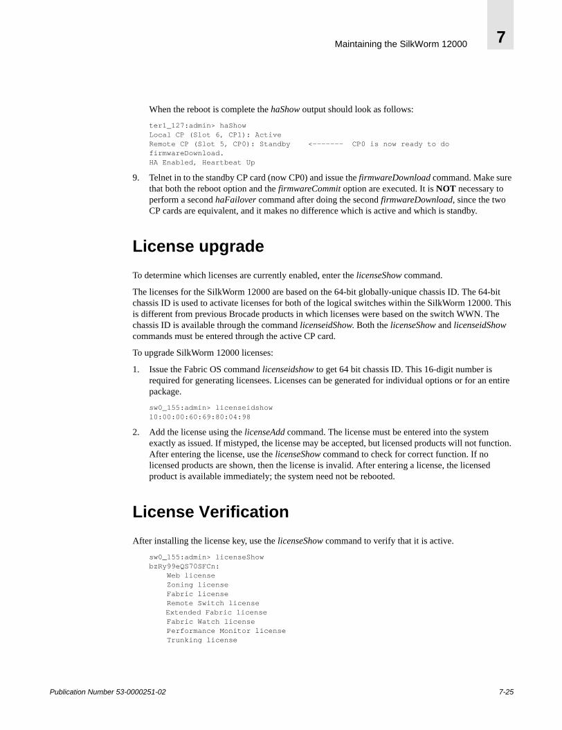
Maintaining the SilkWorm 12000 7
When the reboot is complete the haShow output should look as follows:
ter1_127:admin> haShowLocal CP (Slot 6, CP1): ActiveRemote CP (Slot 5, CP0): Standby <------- CP0 is now ready to do firmwareDownload.HA Enabled, Heartbeat Up
9. Telnet in to the standby CP card (now CP0) and issue the firmwareDownload command. Make sure that both the reboot option and the firmwareCommit option are executed. It is NOT necessary to perform a second haFailover command after doing the second firmwareDownload, since the two CP cards are equivalent, and it makes no difference which is active and which is standby.
License upgradeTo determine which licenses are currently enabled, enter the licenseShow command.
The licenses for the SilkWorm 12000 are based on the 64-bit globally-unique chassis ID. The 64-bit chassis ID is used to activate licenses for both of the logical switches within the SilkWorm 12000. This is different from previous Brocade products in which licenses were based on the switch WWN. The chassis ID is available through the command licenseidShow. Both the licenseShow and licenseidShow commands must be entered through the active CP card.
To upgrade SilkWorm 12000 licenses:
1. Issue the Fabric OS command licenseidshow to get 64 bit chassis ID. This 16-digit number is required for generating licensees. Licenses can be generated for individual options or for an entire package.
sw0_155:admin> licenseidshow10:00:00:60:69:80:04:98
2. Add the license using the licenseAdd command. The license must be entered into the system exactly as issued. If mistyped, the license may be accepted, but licensed products will not function. After entering the license, use the licenseShow command to check for correct function. If no licensed products are shown, then the license is invalid. After entering a license, the licensed product is available immediately; the system need not be rebooted.
License VerificationAfter installing the license key, use the licenseShow command to verify that it is active.
sw0_155:admin> licenseShowbzRy99eQS70SFCn: Web license Zoning license Fabric license Remote Switch license
Extended Fabric license Fabric Watch license Performance Monitor license Trunking license
Publication Number 53-0000251-02 7-25

Maintaining the SilkWorm 120007
7-26 Publication Number 53-0000251-02
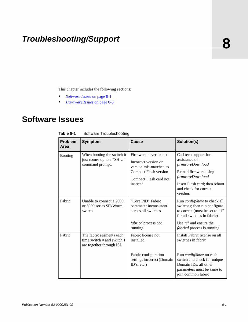
Publication Number 53-0000251-02
8
Troubleshooting/SupportThis chapter includes the following sections:
• Software Issues on page 8-1• Hardware Issues on page 8-5
Software IssuesTable 8-1 Software Troubleshooting
Problem Area
Symptom Cause Solution(s)
Booting When booting the switch it just comes up to a “SH…” command prompt.
Firmware never loaded
Incorrect version or version mis-matched to Compact Flash version
Compact Flash card not inserted
Call tech support for assistance on firmwareDownload
Reload firmware using firmwareDownload
Insert Flash card; then reboot and check for correct version.
Fabric Unable to connect a 2000 or 3000 series SilkWorm switch
“Core PID” Fabric parameter inconsistent across all switches
fabricd process not running
Run configShow to check all switches; then run configure to correct (must be set to “1” for all switches in fabric)
Use “i” and ensure the fabricd process is running
Fabric The fabric segments each time switch 0 and switch 1 are together through ISL
Fabric license not installed
Fabric configuration settings incorrect (Domain ID’s, etc.)
Install Fabric license on all switches in fabric
Run configShow on each switch and check for unique Domain IDs; all other parameters must be same to join common fabric
8-1
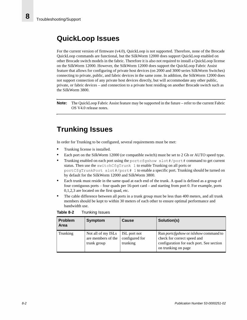
Troubleshooting/Support8
QuickLoop IssuesFor the current version of firmware (v4.0), QuickLoop is not supported. Therefore, none of the Brocade QuickLoop commands are functional, but the SilkWorm 12000 does support QuickLoop enabled on other Brocade switch models in the fabric. Therefore it is also not required to install a QuickLoop license on the SilkWorm 12000. However, the SilkWorm 12000 does support the QuickLoop Fabric Assist feature that allows for configuring of private host devices (on 2000 and 3000 series SilkWorm Switches) connecting to private, public, and fabric devices in the same zone. In addition, the SilkWorm 12000 does not support connection of any private host devices directly, but will accommodate any other public, private, or fabric devices – and connection to a private host residing on another Brocade switch such as the SilkWorm 3800.
Note: The QuickLoop Fabric Assist feature may be supported in the future – refer to the current Fabric OS V4.0 release notes.
Trunking IssuesIn order for Trunking to be configured, several requirements must be met:
• Trunking license is installed.• Each port on the SilkWorm 12000 (or compatible switch) must be set to 2 Gb or AUTO speed type. • Trunking enabled on each port using the portcfgshow slot#/port# command to get current
status. Then use the switchCfgTrunk 1 to enable Trunking on all ports or portCfgTrunkPort slot#/port# 1 to enable a specific port. Trunking should be turned on by default for the SilkWorm 12000 and SilkWorm 3800.
• Each trunk must reside in the same quad at each end of the trunk. A quad is defined as a group of four contiguous ports – four quads per 16-port card – and starting from port 0. For example, ports 0,1,2,3 are located on the first quad, etc.
• The cable difference between all ports in a trunk group must be less than 400 meters, and all trunk members should be kept to within 30 meters of each other to ensure optimal performance and bandwidth use.
Table 8-2 Trunking Issues
Problem Area
Symptom Cause Solution(s)
Trunking Not all of my ISLs are members of the trunk group
ISL port not configured for trunking
Run portcfgshow or islshow command to check for correct speed and configuration for each port. See section on trunking on page
8-2 Publication Number 53-0000251-02

Troubleshooting/Support 8
Web Tools IssuesIf the user is unable to connect to the SilkWorm 12000 using a web browser, the first item to check is the existence of the Web Tools license. Use licenseShow in order to show status of all licenses.
The next most common problem experienced is out of revision web-browser software residing on the host or lack of adequate memory on the host system. Symptoms such as screens missing, not updating properly, or taking too long to refresh are common if this is the case.
Table 8-3 Web Browser Versions for Specific Operating Systems (refer to Brocade Advanced WebTools User Guide for further details)
Host O/S Browser Version Java JDK Version Java Plug-In Version
SUN Solaris Netscape V4.77 JRE 1,2,1or later V1.2.2-02 or later
Microsoft Windows
Netscape V4.77 N/A V1.3 or later
Microsoft Windows
Internet Explorer V5.0
JRE 1.2.1_01a or later V1.2.2_008
Table 8-4 Web Tools Issues
Problem Area
Symptom Cause Solution(s)
Web Tools Unable to connect to the SilkWorm 12000 switch using web-browser
Ethernet connectivity down
Web Tools license not installed
Web Tools processes not running
IP addresses not configured or attempting to use CP0/CP1 IP address for web access
Ping logical switch from host system to check if reachable
Run licenseShow to check; run licenseadd to install Web Tools license on all switches
Run “i” command and check for httpd and webd daemons running (If not Call Tech Support)
Only use logical switch sw0/sw1 IP addresses
Web Tools Web-browser connects, but some sections of switch-view not visible
Incorrect Java JRE version running on host
See above table on web-browser software requirements
Web Tools Access Restricted is displayed in the browser
Security is set incorrectly in Internet Explorer
Change user security preferences to require user to enter username and password
Web Tools Slot tabs are grayed-out
No 16-port card installed (or is disabled)
Install or enable 16-port card
Publication Number 53-0000251-02 8-3
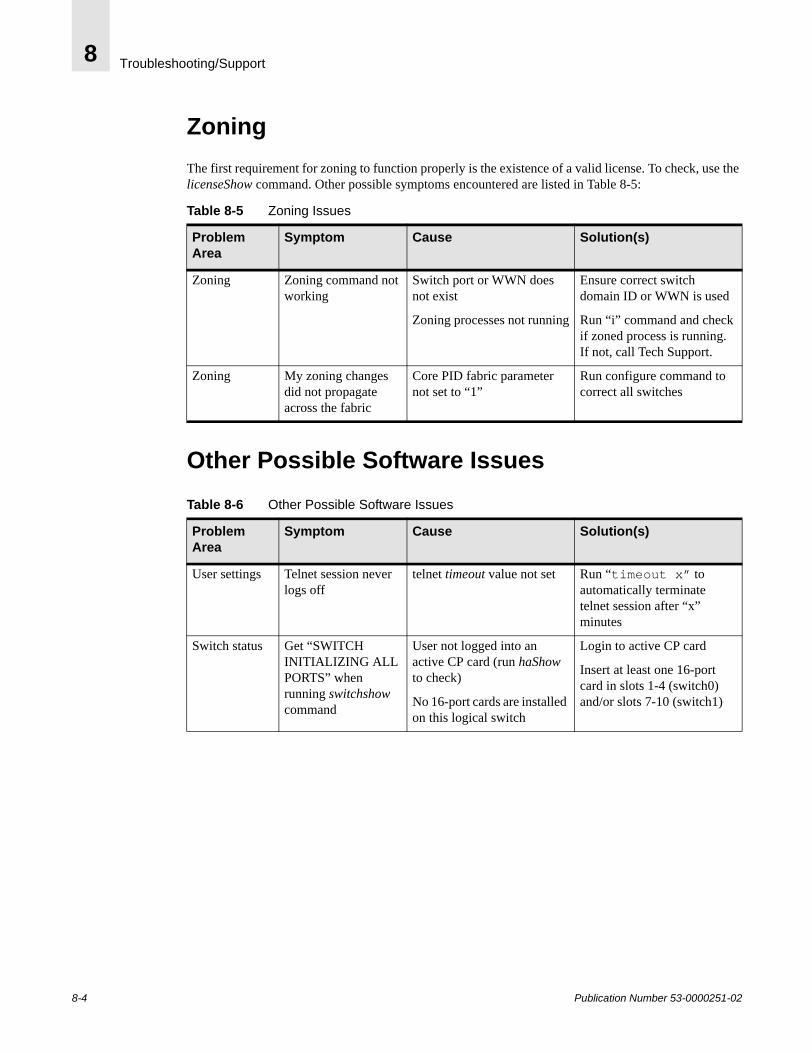
Troubleshooting/Support8
ZoningThe first requirement for zoning to function properly is the existence of a valid license. To check, use the licenseShow command. Other possible symptoms encountered are listed in Table 8-5:
Other Possible Software Issues
Table 8-5 Zoning Issues
Problem Area
Symptom Cause Solution(s)
Zoning Zoning command not working
Switch port or WWN does not exist
Zoning processes not running
Ensure correct switch domain ID or WWN is used
Run “i” command and check if zoned process is running. If not, call Tech Support.
Zoning My zoning changes did not propagate across the fabric
Core PID fabric parameter not set to “1”
Run configure command to correct all switches
Table 8-6 Other Possible Software Issues
Problem Area
Symptom Cause Solution(s)
User settings Telnet session never logs off
telnet timeout value not set Run “timeout x” to automatically terminate telnet session after “x” minutes
Switch status Get “SWITCH INITIALIZING ALL PORTS” when running switchshow command
User not logged into an active CP card (run haShow to check)
No 16-port cards are installed on this logical switch
Login to active CP card
Insert at least one 16-port card in slots 1-4 (switch0) and/or slots 7-10 (switch1)
8-4 Publication Number 53-0000251-02
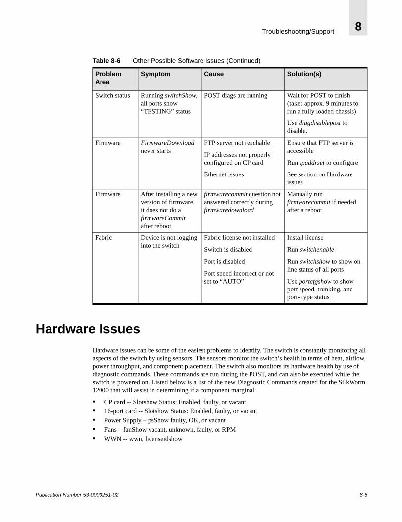
Troubleshooting/Support 8
Hardware IssuesHardware issues can be some of the easiest problems to identify. The switch is constantly monitoring all aspects of the switch by using sensors. The sensors monitor the switch’s health in terms of heat, airflow, power throughput, and component placement. The switch also monitors its hardware health by use of diagnostic commands. These commands are run during the POST, and can also be executed while the switch is powered on. Listed below is a list of the new Diagnostic Commands created for the SilkWorm 12000 that will assist in determining if a component marginal.
• CP card -- Slotshow Status: Enabled, faulty, or vacant• 16-port card -- Slotshow Status: Enabled, faulty, or vacant• Power Supply – psShow faulty, OK, or vacant• Fans – fanShow vacant, unknown, faulty, or RPM• WWN -- wwn, licenseidshow
Switch status Running switchShow, all ports show “TESTING” status
POST diags are running Wait for POST to finish (takes approx. 9 minutes to run a fully loaded chassis)
Use diagdisablepost to disable.
Firmware FirmwareDownload never starts
FTP server not reachable
IP addresses not properly configured on CP card
Ethernet issues
Ensure that FTP server is accessible
Run ipaddrset to configure
See section on Hardware issues
Firmware After installing a new version of firmware, it does not do a firmwareCommit after reboot
firmwarecommit question not answered correctly during firmwaredownload
Manually run firmwarecommit if needed after a reboot
Fabric Device is not logging into the switch
Fabric license not installed
Switch is disabled
Port is disabled
Port speed incorrect or not set to “AUTO”
Install license
Run switchenable
Run switchshow to show on-line status of all ports
Use portcfgshow to show port speed, trunking, and port- type status
Table 8-6 Other Possible Software Issues (Continued)
Problem Area
Symptom Cause Solution(s)
Publication Number 53-0000251-02 8-5
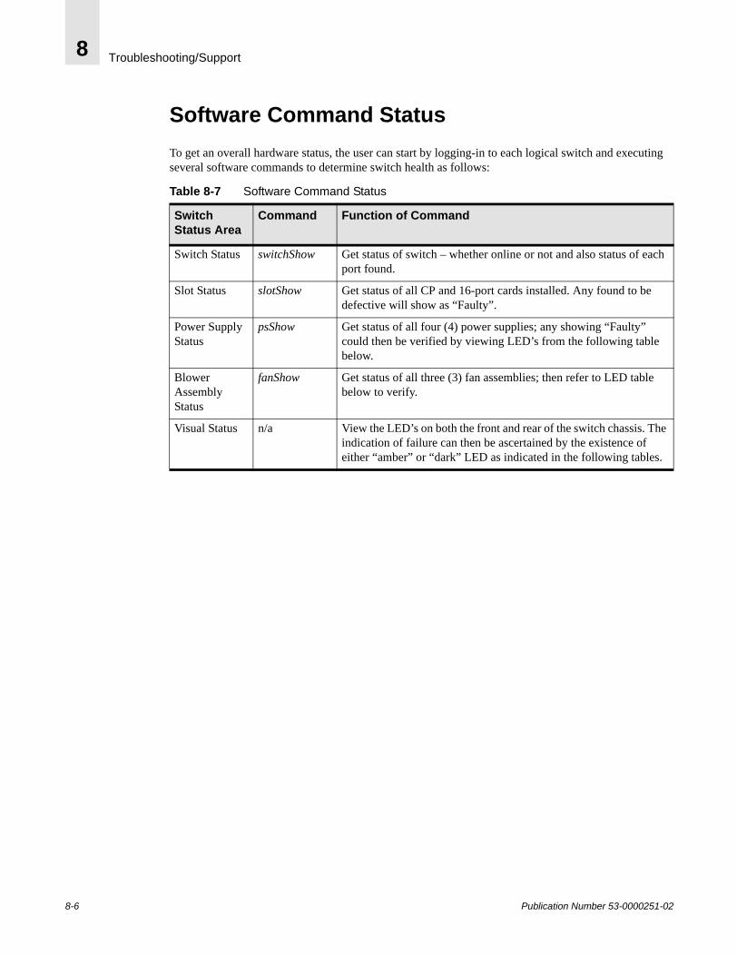
Troubleshooting/Support8
Software Command StatusTo get an overall hardware status, the user can start by logging-in to each logical switch and executing several software commands to determine switch health as follows:
Table 8-7 Software Command Status
Switch Status Area
Command Function of Command
Switch Status switchShow Get status of switch – whether online or not and also status of each port found.
Slot Status slotShow Get status of all CP and 16-port cards installed. Any found to be defective will show as “Faulty”.
Power Supply Status
psShow Get status of all four (4) power supplies; any showing “Faulty” could then be verified by viewing LED’s from the following table below.
Blower Assembly Status
fanShow Get status of all three (3) fan assemblies; then refer to LED table below to verify.
Visual Status n/a View the LED’s on both the front and rear of the switch chassis. The indication of failure can then be ascertained by the existence of either “amber” or “dark” LED as indicated in the following tables.
8-6 Publication Number 53-0000251-02
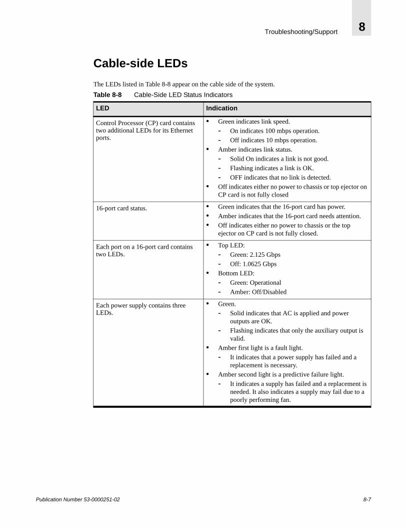
Troubleshooting/Support 8
Cable-side LEDsThe LEDs listed in Table 8-8 appear on the cable side of the system.Table 8-8 Cable-Side LED Status Indicators
LED Indication
Control Processor (CP) card contains two additional LEDs for its Ethernet ports.
• Green indicates link speed.- On indicates 100 mbps operation.- Off indicates 10 mbps operation.
• Amber indicates link status.- Solid On indicates a link is not good.- Flashing indicates a link is OK.- OFF indicates that no link is detected.
• Off indicates either no power to chassis or top ejector on CP card is not fully closed
16-port card status. • Green indicates that the 16-port card has power.• Amber indicates that the 16-port card needs attention.• Off indicates either no power to chassis or the top
ejector on CP card is not fully closed.
Each port on a 16-port card contains two LEDs.
• Top LED:- Green: 2.125 Gbps- Off: 1.0625 Gbps
• Bottom LED: - Green: Operational- Amber: Off/Disabled
Each power supply contains three LEDs.
• Green. - Solid indicates that AC is applied and power
outputs are OK.- Flashing indicates that only the auxiliary output is
valid.• Amber first light is a fault light.
- It indicates that a power supply has failed and a replacement is necessary.
• Amber second light is a predictive failure light. - It indicates a supply has failed and a replacement is
needed. It also indicates a supply may fail due to a poorly performing fan.
Publication Number 53-0000251-02 8-7

Troubleshooting/Support8
Non-cable Side LEDsThe LEDs listed in Table 8-9appear on the non-cable side of the system.
Miscellaneous Hardware Issues
Table 8-9 Non-Cable Side LED Status Indicators
LED Indication
Blower LEDs. • Green indicates that the blower has power.• Amber indicates that the blower lade needs
attention.
Blower system status panel. • Green indicates that the blower assembly has power.
• Amber indicates that the blower assembly needs attention.
Table 8-10 Miscellaneous Hardware Issues
Problem Area
Symptom Cause Solution(s)
Ethernet Cannot connect to network
IP addresses or subnet mask incorrect for customer network
Ethernet port not syncing with customer’s ethernet hub or switch
Run ipaddrshow 4
To check; then ipaddrset 0 or 1 for logical switches, ipaddrset 2 or 3 for CP cards
Some hubs and switches not compatible with devices set to “auto-negotiate”
Ethernet Cannot run ipaddrshow 4 to get IP address status
Not logged into active CP card
Only CP card IP addresses accessible – no IP access to logical switches
Run hashow to check for active or standby status then login to active CP card using serial port or telnet.
Fabric OS not running; Run the “i” command and check for existence of fabricd running. If not, call Tech Support.
Ethernet Cannot connect to a host on 10.x.x.x subnet
10.x.x.x IP address range is conflicting with backplane subnet
Call Tech Support
Hardware status
The amber LEDs on the 16-port cards are lit up, what do they mean?
Refer to LED status tables
8-8 Publication Number 53-0000251-02

Troubleshooting/Support 8
Diagnostic CommandsEvery time that the SilkWorm 12000 powers up it runs POST (Power On Self Test), the switch runs a series of diagnostic tests to determine the health of the switch and each of its components. This process takes approximately ten minutes to run POST with eight (8) 16-port cards inserted. In order to disable POST diagnostics, the user can execute diagdisablepost (or diagenablepost to re-enable). This will allow the chassis to be rebooted in a more timely manner, but should not be disabled during normal operations.
Publication Number 53-0000251-02 8-9

Troubleshooting/Support8
8-10 Publication Number 53-0000251-02

Publication Number 53-0000251-02
Glossary
8b/10b encoding
An encoding scheme that converts each 8-bit byte into 10 bits. Used to balance ones and zeros in high-speed transports.
address identifier
A 24-bit or 8-bit value used to identify the source or destination of a frame.
AL_PA Arbitrated loop physical address. A unique 8-bit value assigned during loop initialization to a port in an arbitrated loop.
alias An alternate name for an element or group of elements in the fabric. Aliases can be used to simplify the entry of port numbers and WWNs when creating zones.
alias address identifier
An address identifier recognized by a port in addition to its standard identifier. An alias address identifier may be shared by multiple ports. See also alias.
alias AL_PA An AL_PA value recognized by an L_Port in addition to the AL_PA assigned to the port. See also AL_PA.
alias server A fabric software facility that supports multicast group management.
ANSI American National Standards Institute. The governing body for Fibre Channel standards in the U.S.A.
API Application programming interface. A defined protocol that allows applications to interface with a set of services.
arbitratedloop
A shared 100 MB/s Fibre Channel transport structured as a loop. Can support up to 126 devices and one fabric attachment. See also topology.
ASIC Application specific integrated circuit.
ATM Asynchronous transfer mode. A transport used for transmitting data over LANs or WANs that transmit fixed-length units of data. Provides any-to-any connectivity, and allows nodes to transmit simultaneously.
authentication The process of verifying that an entity (such as a switch) in a fabric is what it claims to be. See also digital certificate, switch-to-switch authentication.
AW_TOV Arbitration wait time-out value. The minimum time an arbitrating L_Port waits for a response before beginning loop initialization.
backup FCS switch
Backup fabric configuration server switch. The switch or switches assigned as backup in case the primary FCS switch fails. See also FCS switch, primary FCS switch.
bandwidth The total transmission capacity of a cable, link, or system. Usually measured in bps (bits per second). May also refer to the range of transmission frequencies available to a link or system. See also throughput.
BB_Credit Buffer-to-buffer credit. The number of frames that can be transmitted to a directly connected recipient or within an arbitrated loop. Determined by the number of receive buffers available. See also buffer-to-buffer flow control, EE_Credit.
Glossary-1

beacon When all the port LEDs on a switch are set to flash from one side of the switch to the other, to enable identification of an individual switch in a large fabric. A switch can be set to beacon by telnet command or through Brocade Web Tools.
beginning running disparity
The disparity at the transmitter or receiver when the special character associated with an ordered set is encoded or decoded. See also disparity.
BER Bit error rate. The rate at which bits are expected to be received in error. Expressed as the ratio of error bits to total bits transmitted. See also error.
blind-mate Connector
A two way connector used in some SilkWorm switches to provide a connection between the motherboard and the power supply.
block As applies to Fibre Channel, upper-level application data that is transferred in a single sequence.
broadcast The transmission of data from a single source to all devices in the fabric, regardless of zoning. See also multicast, unicast.
buffer-to-buffer flow control
Management of the frame transmission rate in either a point-to-point topology or in an arbitrated loop. See also BB_Credit.
cascade Two or more interconnected Fibre Channel switches. SilkWorm 2000 and later switches can be cascaded up to 239 switches, with a recommended maximum of seven interswitch links (no path longer than eight switches). See also fabric, ISL.
chassis The metal frame in which the switch and switch components are mounted.
circuit An established communication path between two ports. Consists of two virtual circuits capable of transmitting in opposite directions. See also link.
Class 1 The class of frame switching service for a dedicated connection between two communicating ports (also called connection-oriented service), with acknowledgement of delivery or nondelivery of frames.
Class 2 A connectionless class of frame switching service that includes acknowledgement of delivery or nondelivery of frames.
Class 3 A connectionless class of frame switching service that does not include acknowledgement of delivery or nondelivery of frames. Can be used to provide a multicast connection between the frame originator and recipients, with acknowledgement of delivery or nondelivery of frames.
Class F The class of frame switching service for a direct connection between two switches, allowing communication of control traffic between the E_Ports, with notification of delivery or nondelivery of data.
class of service A specified set of delivery characteristics and attributes for frame delivery.
CLI Command line interface. Interface that depends entirely on the use of commands, such as through telnet or SNMP, and does not involve a GUI.
comma A unique pattern (either 1100000 or 0011111) used in 8B/10B encoding to specify character alignment within a data stream. See also K28.5.
community (SNMP)
A relationship between a group of SNMP managers and an SNMP agent, in which authentication, access control, and proxy characteristics are defined. See also SNMP.
Glossary-2 Publication Number 53-0000251-02

connection initiator
A port that has originated a Class 1 dedicated connection and received a response from the recipient.
connection recipient
A port that has received a Class 1 dedicated connection request and transmitted a response to the originator.
CRC Cyclic redundancy check. A transmission error check which is included in every data frame.
credit As applies to Fibre Channel, the number of receive buffers available for transmission of frames between ports. See also BB_Credit, EE_Credit.
cut-through A switching technique that allows the route for a frame to be selected as soon as the destination address is received. See also route.
data word A type of transmission word that occurs within frames. The frame header, data field, and CRC all consist of data words. See also frame, ordered set, transmission word.
defined zone configuration
The set of all zone objects defined in the fabric. May include multiple zone configurations. See also enabled zone configuration, zone configuration.
digital certificate
An electronic document issued by a CA (certificate authority) to an entity, and containing the public key and identity of the entity. Entities in a secure fabric are authenticated based on these certificates. See also authentication, CA, public key.
disparity The proportion of ones and zeros in an encoded character. “Neutral disparity” means an equal number of each, “positive disparity” means a majority of ones, and “negative disparity” means a majority of zeros.
DLS Dynamic load sharing. Dynamic distribution of traffic over available paths. Allows for recomputing of routes when an Fx_Port or E_Port changes status.
domain ID Unique identifier for all switches in a fabric, used in routing frames. Usually automatically assigned by the principal switch, but can be assigned manually. The domain ID for a SilkWorm switch can be any integer between| 1 and 239.
E_D_TOV Error detect time-out value. The minimum amount of time a target waits for a sequence to complete before initiating recovery. Can also be defined as the maximum time allowed for a round-trip transmission before an error condition is declared. See also R_A_TOV, RR_TOV.
E_Port Expansion port. A type of switch port that can be connected to an E_Port on another switch to create an ISL. See also ISL.
EE_Credit End-to-end credit. The number of receive buffers allocated by a recipient port to an originating port. Used by Class 1 and 2 services to manage the exchange of frames across the fabric between source and destination. See also BB_Credit, end-to-end flow control.
EIA rack A storage rack that meets the standards set by the Electronics Industry Association.
enabled zone configuration
The currently enabled configuration of zones. Only one configuration can be enabled at a time. See also defined zone configuration, zone configuration.
end-to-end flow control
Governs flow of class 1 and 2 frames between N_Ports. See also EE_Credit.
Publication Number 53-0000251-02 Glossary-3

Entry Fabric The basic Brocade software license that allows one E_Port per switch.
error As applies to Fibre Channel, a missing or corrupted frame, time-out, loss of synchronization, or loss of signal (link errors). See also loop failure.
exchange The highest level Fibre Channel mechanism used for communication between N_Ports. Composed of one or more related sequences, and can work in either one or both directions.
F_Port Fabric port. A port that is able to transmit under fabric protocol and interface over links. Can be used to connect an N_Port to a switch. See also FL_Port, Fx_Port.
fabric A Fibre Channel network containing two or more switches in addition to hosts and devices. May also be referred to as a switched fabric. See also cascade, SAN, topology.
fabric name The unique identifier assigned to a fabric and communicated during login and port discovery.
FC-AL-3 The Fibre Channel Arbitrated Loop standard defined by ANSI. Defined on top of the FC-PH standards.
FC-FLA The Fibre Channel Fabric Loop Attach standard defined by ANSI.
FCIA Fibre Channel Industry Association. An international organization of Fibre Channel industry professionals. Provides oversight of ANSI and industry developed standards, among other tasks.
FCP Fibre channel protocol. Mapping of protocols onto the Fibre Channel standard protocols. For example, SCSI FCP maps SCSI-3 onto Fibre Channel.
FC-PH-1, 2, 3 The Fibre Channel Physical and Signalling Interface standards defined by ANSI.
FC-PI The Fibre Channel Physical Interface standard defined by ANSI.
FC-PLDA The Fibre Channel Private Loop Direct Attach standard defined by ANSI. Applies to the operation of peripheral devices on a private loop.
FCS switch Fabric configuration server switch. One or more designated SilkWorm switches that store and manage the configuration and security parameters for all switches in the fabric. FCS switches are designated by WWN, and the list of designated switches is communicated fabric-wide. See also backup FCS switch, primary FCS switch.
FC-SW-2 The second generation of the Fibre Channel Switch Fabric standard defined by ANSI. Specifies tools and algorithms for the interconnection and initialization of Fibre Channel switches in order to create a multi-switch Fibre Channel fabric.
Fibre Channel transport
A protocol service that supports communication between Fibre Channel service providers. See also FSP.
FIFO First In, First Out.
fill word An IDLE or ARB ordered set that is transmitted during breaks between data frames to keep the Fibre Channel link active.
firmware The basic operating system provided with the hardware.
Glossary-4 Publication Number 53-0000251-02

FL_Port Fabric loop port. A port that is able to transmit under fabric protocol and also has arbitrated loop capabilities. Can be used to connect an NL_Port to a switch. See also F_Port, Fx_Port.
FLOGI Fabric login. The process by which an N_Port determines whether a fabric is present, and if so, exchanges service parameters with it. See also PLOGI.
frame The Fibre Channel structure used to transmit data between ports. Consists of a start-of-frame delimiter, header, any optional headers, data payload, cyclic redundancy check (CRC), and end-of-frame delimiter. There are two types of frames: Link control frames (transmission acknowledgements, etc.) and data frames.
FRU Field-replaceable unit. A component that can be replaced on site.
FS Fibre channel service. A service that is defined by Fibre Channel standards and exists at a well-known address. For example, the Simple Name Server is a Fibre Channel service. See also FSP.
FSP Fibre channel service protocol. The common protocol for all fabric services, transparent to the fabric type or topology. See also FS.
FSPF Fabric shortest path first. Brocade’s routing protocol for Fibre Channel switches.
full-duplex A mode of communication that allows the same port to simultaneously transmit and receive frames. See also half-duplex.
Full Fabric The Brocade software license that allows multiple E_Ports on a switch, making it possible to create multiple ISL links.
Fx_Port A fabric port that can operate as either an F_Port or FL_Port. See also F_Port, FL_Port.
G_Port Generic port. A port that can operate as either an E_Port or F_Port. A port is defined as a G_Port when it is not yet connected or has not yet assumed a specific function in the fabric.
gateway Hardware that connects incompatible networks by providing translation for both hardware and software.
GBIC Gigabit interface converter. A removable serial transceiver module that allows gigabaud physical-level transport for Fibre Channel and gigabit ethernet.
Gbps Gigabits per second (1,062,500,000 bits/second).
GBps GigaBytes per second (1,062,500,000 bytes/second).
half-duplex A mode of communication that allows a port to either transmit or receive frames at any time, but not simultaneously (with the exception of link control frames, which can be transmitted at any time). See also full-duplex.
hard address The AL_PA that an NL_Port attempts to acquire during loop initialization.
hardware translativemode
A method for achieving address translation. The following two hardware translative modes are available to a QuickLoop enabled switch:
• Standard translative mode: Allows public devices to communicate with private devices that are directly connected to the fabric.
• QuickLoop mode: Allows initiator devices to communicate with private or public devices that are not in the same loop.
Publication Number 53-0000251-02 Glossary-5
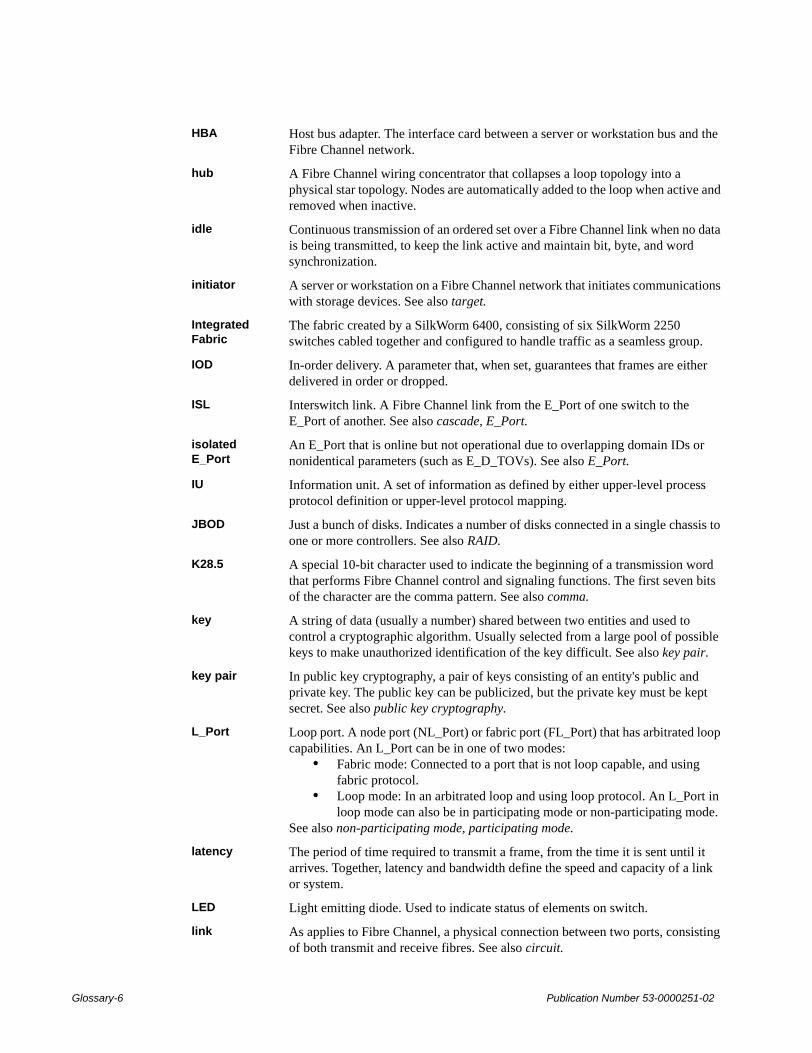
HBA Host bus adapter. The interface card between a server or workstation bus and the Fibre Channel network.
hub A Fibre Channel wiring concentrator that collapses a loop topology into a physical star topology. Nodes are automatically added to the loop when active and removed when inactive.
idle Continuous transmission of an ordered set over a Fibre Channel link when no data is being transmitted, to keep the link active and maintain bit, byte, and word synchronization.
initiator A server or workstation on a Fibre Channel network that initiates communications with storage devices. See also target.
Integrated Fabric
The fabric created by a SilkWorm 6400, consisting of six SilkWorm 2250 switches cabled together and configured to handle traffic as a seamless group.
IOD In-order delivery. A parameter that, when set, guarantees that frames are either delivered in order or dropped.
ISL Interswitch link. A Fibre Channel link from the E_Port of one switch to the E_Port of another. See also cascade, E_Port.
isolated E_Port
An E_Port that is online but not operational due to overlapping domain IDs or nonidentical parameters (such as E_D_TOVs). See also E_Port.
IU Information unit. A set of information as defined by either upper-level process protocol definition or upper-level protocol mapping.
JBOD Just a bunch of disks. Indicates a number of disks connected in a single chassis to one or more controllers. See also RAID.
K28.5 A special 10-bit character used to indicate the beginning of a transmission word that performs Fibre Channel control and signaling functions. The first seven bits of the character are the comma pattern. See also comma.
key A string of data (usually a number) shared between two entities and used to control a cryptographic algorithm. Usually selected from a large pool of possible keys to make unauthorized identification of the key difficult. See also key pair.
key pair In public key cryptography, a pair of keys consisting of an entity's public and private key. The public key can be publicized, but the private key must be kept secret. See also public key cryptography.
L_Port Loop port. A node port (NL_Port) or fabric port (FL_Port) that has arbitrated loop capabilities. An L_Port can be in one of two modes:
• Fabric mode: Connected to a port that is not loop capable, and using fabric protocol.
• Loop mode: In an arbitrated loop and using loop protocol. An L_Port in loop mode can also be in participating mode or non-participating mode.
See also non-participating mode, participating mode.
latency The period of time required to transmit a frame, from the time it is sent until it arrives. Together, latency and bandwidth define the speed and capacity of a link or system.
LED Light emitting diode. Used to indicate status of elements on switch.
link As applies to Fibre Channel, a physical connection between two ports, consisting of both transmit and receive fibres. See also circuit.
Glossary-6 Publication Number 53-0000251-02

link services A protocol for link-related actions.
LIP Loop initialization primitive. The signal used to begin initialization in a loop. Indicates either loop failure or resetting of a node.
LM_TOV Loop master time-out value. The minimum time that the loop master waits for a loop initialization sequence to return.
loop circuit A temporary bidirectional communication path established between L_Ports.
loop failure Loss of signal within a loop for any period of time, or loss of synchronization for longer than the time-out value.
loop initialization
The logical procedure used by an L_Port to discover its environment. Can be used to assign AL_PA addresses, detect loop failure, or reset a node.
Loop_ID A hex value representing one of the 127 possible AL_PA values in an arbitrated loop.
looplet A set of devices connected in a loop to a port that is a member of another loop.
LPSM Loop port state machine. The logical entity that performs arbitrated loop protocols and defines the behavior of L_Ports when they require access to an arbitrated loop.
LWL Long wavelength. A type of fiber optic cabling that is based on 1300mm lasers and supports link speeds of 1.0625 Gbps. May also refer to the type of GBIC or SFP. See also SWL.
MIB Management information base. An SNMP structure to help with device management, providing configuration and device information.
multicast The transmission of data from a single source to multiple specified N_Ports (as opposed to all the ports on the network). See also broadcast, unicast.
multimode A fiber optic cabling specification that allows up to 500 meters between devices.
N_Port Node port. A port on a node that can connect to a Fibre Channel port or to another N_Port in a point-to-point connection. See also NL_Port, Nx_Port.
name server Frequently used to indicate Simple Name Server. See also SNS.
NL_Port Node loop port. A node port that has arbitrated loop capabilities. Used to connect an equipment port to the fabric in a loop configuration through an FL_Port. See also N_Port, Nx_Port.
node A Fibre Channel device that contains an N_Port or NL_Port.
node name The unique identifier for a node, communicated during login and port discovery.
non-participating mode
A mode in which an L_Port in a loop is inactive and cannot arbitrate or send frames, but can retransmit any received transmissions. This mode is entered if there are more than 127 devices in a loop and an AL_PA cannot be acquired. See also L_Port, participating mode.
Nx_Port A node port that can operate as either an N_Port or NL_Port.
Publication Number 53-0000251-02 Glossary-7

ordered set A transmission word that uses 8B/10B mapping and begins with the K28.5 character. Ordered sets occur outside of frames, and include the following items:
• Frame delimiters: Mark frame boundaries and describe frame contents.• Primitive signals: Indicate events.• Primitive sequences: Indicate or initiate port states.
Ordered sets are used to differentiate Fibre Channel control information from data frames and to manage the transport of frames.
packet A set of information transmitted across a network. See also frame.
participating mode
A mode in which an L_Port in a loop has a valid AL_PA and can arbitrate, send frames, and retransmit received transmissions. See also L_Port, non-participating mode.
path selection The selection of a transmission path through the fabric. Brocade switches use the FSPF protocol. See also FSPF.
phantom address
An AL_PA value that is assigned to an device that is not physically in the loop. Also known as phantom AL_PA.
phantom device
A device that is not physically in an arbitrated loop but is logically included through the use of a phantom address.
PKI Public key infrastructure. An infrastructure that is based on public key cryptography and CA (certificate authority), and uses digital certificates. See also CA, digital certificate, public key cryptography.
PKI certification utility
Public key infrastructure certification utility. A utility that makes it possible to collect certificate requests from switches and load certificates to switches. See also digital certificate, PKI.
PLOGI Port login. The port-to-port login process by which initiators establish sessions with targets. See also FLOGI.
point-to-point A Fibre Channel topology that employs direct links between each pair of communicating entities. See also topology.
Port_Name The unique identifier assigned to a Fibre Channel port. Communicated during login and port discovery.
port cage The metal casing extending out of the optical port on the switch, and in which the SFP can be inserted.
POST Power on self-test. A series of tests run by a switch after it is turned on.
primary FCS switch
Primary fabric configuration server switch. The switch that actively manages the configuration and security parameters for all switches in the fabric. See also backup FCS switch, FCS switch.
private device A device that supports arbitrated loop protocol and can interpret 8-bit addresses, but cannot log into the fabric.
private key The secret half of a key pair. See also key, key pair.
private loop An arbitrated loop that does not include a participating FL_Port.
privateNL_Port
An NL_Port that communicates only with other private NL_Ports in the same loop and does not log into the fabric.
protocol A defined method and set of standards for communication.
Glossary-8 Publication Number 53-0000251-02

public device A device that supports arbitrated loop protocol, can interpret 8-bit addresses, and can log into the fabric.
public key The public half of a key pair. See also key, key pair.
public key cryptography
A type of cryptography which uses a key pair, with the two keys in the pair called at different points in the algorithm. The sender uses the recipient's public key to encrypt the message, and the recipient uses the recipient’s private key to decrypt it. See also key pair, PKI.
public loop An arbitrated loop that includes a participating FL_Port, and may contain both public and private NL_Ports.
public NL_Port An NL_Port that logs into the fabric, can function within either a public or a private loop, and can communicate with either private or public NL_Ports.
quad A group of four adjacent ports that share a common pool of frame buffers.
R_A_TOV Resource allocation time-out value. The maximum time a frame can be delayed in the fabric and still be delivered. See also E_D_TOV, RR_TOV.
RAID Redundant array of independent disks. A collection of disk drives that appear as a single volume to the server and are fault tolerant through mirroring or parity checking. See also JBOD.
request rate The rate at which requests arrive at a servicing entity. See also service rate.
route As applies to a fabric, the communication path between two switches. May also apply to the specific path taken by an individual frame, from source to destination. See also FSPF.
routing The assignment of frames to specific switch ports, according to frame destination.
RR_TOV Resource recovery time-out value. The minimum time a target device in a loop waits after a LIP before logging out a SCSI initiator. See also E_D_TOV, R_A_TOV.
RSCN Registered state change notification. A switch function that allows notification of fabric changes to be sent from the switch to specified nodes.
SAN Storage area network. A network of systems and storage devices that communicate using Fibre Channel protocols. See also fabric.
sectelnet A protocol similar to Telnet but with encrypted passwords for increased security.
security policy A set of rules that determine how security is implemented in a fabric. Security policies can be customized.
sequence A group of related frames transmitted in the same direction between two N_Ports.
service rate The rate at which an entity can service requests. See also request rate.
SFP Cable A cable specifically designed for use with an SFP. Not compatible with GBICs.
SI Sequence initiative.
SilkWorm The brand name for the Brocade family of switches.
single mode The fiber optic cabling standard that corresponds to distances of up to 10 km between devices.
Publication Number 53-0000251-02 Glossary-9

SNMP Simple network management protocol. An internet management protocol that uses either IP for network-level functions and UDP for transport-level functions, or TCP/IP for both. Can be made available over other protocols, such as UDP/IP, because it does not rely on the underlying communication protocols. See also community (SNMP).
SNS Simple name server. A switch service that stores names, addresses, and attributes for up to 15 minutes, and provides them as required to other devices in the fabric. SNS is defined by Fibre Channel standards and exists at a well-known address. May also be referred to as directory service. See also FS.
switch Hardware that routes frames according to Fibre Channel protocol and is controlled by software.
switch name The arbitrary name assigned to a switch.
switch port A port on a switch. Switch ports can be E_Ports, F_Ports, or FL_Ports.
switch-to-switch authentication
The process of authenticating both switches in a switch-to-switch connection using digital certificates. See also authentication, digital certificate.
SWL Short wavelength. A type of fiber optic cabling that is based on 850mm lasers and supports 1.0625 Gbps link speeds. May also refer to the type of GBIC or SFP. See also LWL.
target A storage device on a Fibre Channel network. See also initiator.
tenancy The time from when a port wins arbitration in a loop until the same port returns to the monitoring state. Also referred to as loop tenancy.
throughput The rate of data flow achieved within a cable, link, or system. Usually measured in bps (bits per second). See also bandwidth.
topology As applies to Fibre Channel, the configuration of the Fibre Channel network and the resulting communication paths allowed. There are three possible topologies:
• Point to point: A direct link between two communication ports.• Switched fabric: Multiple N_Ports linked to a switch by F_Ports.• Arbitrated loop: Multiple NL_Ports connected in a loop.
translative mode
A mode in which private devices can communicate with public devices across the fabric.
transmission character
A 10-bit character encoded according to the rules of the 8B/10B algorithm.
transmission word
A group of four transmission characters.
trap (SNMP) The message sent by an SNMP agent to inform the SNMP management station of a critical error. See also SNMP.
tunneling A technique for enabling two networks to communicate when the source and destination hosts are both on the same type of network, but are connected by a different type of network.
U_Port Universal port. A switch port that can operate as a G_Port, E_Port, F_Port, or FL_Port. A port is defined as a U_Port when it is not connected or has not yet assumed a specific function in the fabric.
Glossary-10 Publication Number 53-0000251-02

UDP User datagram protocol. A protocol that runs on top of IP and provides port multiplexing for upper-level protocols.
ULP Upper-level protocol. The protocol that runs on top of Fibre Channel. Typical upper-level protocols are SCSI, IP, HIPPI, and IPI.
ULP_TOV Upper-level time-out value. The minimum time that a SCSI ULP process waits for SCSI status before initiating ULP recovery.
unicast The transmission of data from a single source to a single destination. See also broadcast, multicast.
well-known address
As pertaining to Fibre Channel, a logical address defined by the Fibre Channel standards as assigned to a specific function, and stored on the switch.
workstation A computer used to access and manage the fabric. May also be referred to as a management station or host.
WWN Worldwide name. An identifier that is unique worldwide. Each entity in a fabric has a separate WWN.
zone A set of devices and hosts attached to the same fabric and configured as being in the same zone. Devices and hosts within the same zone have access permission to others in the zone, but are not visible to any outside the zone.
zone configuration
A specified set of zones. Enabling a configuration enables all zones in that configuration. See also defined zone configuration, enabled zone configuration.
Publication Number 53-0000251-02 Glossary-11

Glossary-12 Publication Number 53-0000251-02


![initial configuration of fibre channel switches revision 0 ... · The switch examples used in this document include the Brocade SilkWorm 200E, ... DHCP [Off]: IP address is being](https://img.pdfslide.net/doc/110x75/5b31ddb37f8b9ae1108bf8fd/initial-configuration-of-fibre-channel-switches-revision-0-the-switch-examples.jpg)