Embed Size (px)
Citation preview

DATA CENTER
Brocade VCS Fabric Technology and NAS with NFS Validation Test
NetApp/VMware vSphere 5.0 Red Hat Enterprise Linux
This material outlines sample configurations and associated test results of Brocade® VCS® Fabric technology with NFS file servers.

DATA CENTER SOLUTION GUIDE
Brocade VCS Fabric Technology and NAS with NFS Validation Test 2 of 52
CONTENTS
Contents................................................................................................................................................................................................................................................2 1 Preface .............................................................................................................................................................................................................................................4
1.1 Overview ...................................................................................................................................................................4 1.2 Purpose of This Document......................................................................................................................................4 1.3 Audience...................................................................................................................................................................4 1.4 Objectives .................................................................................................................................................................4 1.5 Brocade VCS Features.............................................................................................................................................5 1.6 Summary ..................................................................................................................................................................6 1.7 Related Documents .................................................................................................................................................6 1.8 About Brocade..........................................................................................................................................................7
2. Test Case #1: NetApp FAS3050............................................................................................................................................................................................8 2.1 Test Case #1 Summary ...........................................................................................................................................8 2.2 Topology ...................................................................................................................................................................9 2.3 Hardware Resources ...............................................................................................................................................9 2.4 Compute Resources ..............................................................................................................................................10 2.5 Software Resources...............................................................................................................................................10 2.6 Test 1: I/O Verification...........................................................................................................................................10 2.7 Test 2: Link Failure ................................................................................................................................................12 2.8 Test 3: Active Path Failure.....................................................................................................................................14 2.9 Test 4: Switch Failure ............................................................................................................................................17 2.10 Test 5: vMotion with Link/Path Failure ..............................................................................................................22
3. Test Case #2: Red Hat Enterprise Linux NFS Server....................................................................................................................................................30 3.1 Test Case #2 Results.............................................................................................................................................30 3.2 Topology .................................................................................................................................................................31 3.3 Hardware Resources .............................................................................................................................................31 3.4 Compute Resources ..............................................................................................................................................31 3.5 Software Resources...............................................................................................................................................32 3.6 Test 1: I/O Verification...........................................................................................................................................32 3.7 Test 2: Link Failure ................................................................................................................................................34 3.8 Test 3: Switch Failure ............................................................................................................................................36 3.8.1 Test Procedure....................................................................................................................................................37
Appendix A: Test Case #1............................................................................................................................................................................................................41 Brocade VCS Deployment Considerations: Dynamic LACP vLAG with NetApp..........................................................41 Brocade VDX Deployment Considerations: Static LACP vLAG with ESXi Server and Brocade 1020 CNA..............43 Brocade VCS Deployment Considerations: Enable Brocade VDX Jumbo Frame Support ........................................45 Brocade VCS Deployment Considerations: Enable Ethernet Pause/Flow Control Support .....................................45 NetApp FAS3050 Deployment Procedure: Volume and VIF Creation........................................................................46
NetApp Volume Creation .......................................................................................................................................46 NetApp VIF Creation...............................................................................................................................................46

DATA CENTER SOLUTION GUIDE
Brocade VCS Fabric Technology and NAS with NFS Validation Test 3 of 52
VMware vSphere Client Deployment Procedure: ESXi Datastore Creation ...............................................................46 ESX Datastore Creation .........................................................................................................................................46
VMware vSphere Client Deployment Procedure: Virtual Machine Creation..............................................................46 VM Creation............................................................................................................................................................46
VMware ESXi Deployment Procedure: NIC Teaming for vSwitch................................................................................47 VMware ESXi NIC Teaming for vSwitch.................................................................................................................47
Appendix b: Test Case #2............................................................................................................................................................................................................48 Brocade VCS Fabric Configuration: Static LACP vLAG with Red Hat Enterprise Linux NFS Server and Brocade 1020 CNA........................................................................................................................................................48 Red Hat Enterprise Linux NFS Server: NIC Bonding Configuration ............................................................................50
Appendix C: References...............................................................................................................................................................................................................52

DATA CENTER SOLUTION GUIDE
Brocade VCS Fabric Technology and NAS with NFS Validation Test 4 of 52
1 PREFACE
1.1 Overview As per the Gartner 2011 NAS Magic Quadrant report, the midrange and high-end Network-Attached Storage (NAS) market for 2010 experienced a growth rate of 33 percent over 2009 in terms of hardware vendor revenue. This favorable growth rate was a result of several factors: fast-growing unstructured file data, widespread availability of data de-duplication/compression in NAS storage solutions, ease of management, support of virtualized environments such as VMware, and the flexibility of unified storage. 1
Additionally, IDC predicts that by 2014 more than 83 percent of enterprise storage system capacity will be shipped for file-based data, taking the Compound Annual Growth Rate (CAGR) for file serving storage capacity to 2.5 times the CAGR for block storage capacity2.
As also discussed in the Gartner 2011 NAS Magic Quadrant report, NAS support of the VMware environment has become more prominent in the past year, as more and more NAS vendors have invested in this area to increase the appeal of their products. Additionally, NAS products use industry-standard remote file protocols, including Network File System (NFS).
The Gartner report also observes that because some applications, such as Oracle database applications and VMware, are built on files instead of blocks, NAS is increasingly used as application storage for those environments, providing ease-of-use benefits to users as compared with storage arrays that use block protocols, which may offer higher performance than NAS. As a result, many midrange and high-end NAS products are used to consolidate storage for both server applications and home directories for PC clients.
Given the tremendous growth rates in NAS and the large number of existing deployments, this presents an opportunity to demonstrate that Brocade® VCS® Fabric technology interoperates with the underlying NFS protocol used by these systems.
1.2 Purpose of This Document This document provides the validation of Brocade VCS Fabric technology with two implementations of the Network File System (NFS) Protocol, including both the NetApp FAS3050 NFS filer and Red Hat Enterprise Linux configured as an NFS server. This validation demonstrates that existing deployments using NFS will interoperate with Brocade VCS fabrics and exhibit resiliency to failure scenarios. This ensures that inputs/outputs (I/Os) between clients and servers operate in a non-disruptive manner.
The testing demonstrates NFS interoperability with Brocade VCS Fabric technology, while providing sample configurations and test results associated with fabric failover scenarios. This document should provide peace of mind for both network and storage administrators and architects who are already using NFS and are considering the use of Brocade VCS Fabric technology.
1.3 Audience The content in this document is written for a technical audience, including solution architects, solutioneers, system engineers, and technical development representatives. This document assumes the audience is familiar with Brocade VCS Fabric technology.
1.4 Objectives The objectives of this document are to evaluate NFS protocol interoperability with Brocade VCS Fabric technology in the following two test cases:
Test Case #1 with the NetApp FAS3050: This test consists of a 6-node Brocade VCS fabric with 2 ESXi hosts using Brocade 1020 FCoE (Fiber Channel over Ethernet) CNAs and the NetApp FAS3050. For this test, the Virtual Machine (VM) data store associated with the ESXi cluster resides on a volume of the NetApp FAS3050. Iometer is used as a measurement and characterization tool for this test.

DATA CENTER SOLUTION GUIDE
Brocade VCS Fabric Technology and NAS with NFS Validation Test 5 of 52
Test Case #2 with Red Hat Enterprise Linux NFS server: This test consists of a 4-node Brocade VCS fabric with a Red Hat Enterprise Linux NFS server. For this test, Spirent is used as a characterization tool for the NFS clients. Spirent emulates many NFS clients accessing the Red Hat Enterprise Linux NFS server share. Each of the Spirent-emulated NFS clients mounted the NFS share of the Red Hat Enterprise Linux NFS server.
Both tests demonstrate that the topology of the network can change, with limited implication to the application, using NFS as an underlying protocol. Please note that this does not include a full configuration or validation of specific features on ESXi, Red Hat, NetApp, and VMware.
1.5 Brocade VCS Features The following Brocade VCS features are used in the validation testing for both test cases. These features are considered best practices when utilizing NFS over a Brocade VCS fabric.
Please refer to Appendices A and B for the actual configuration procedures for these features.
1.5.1 Brocade Inter-Switch Link (ISL) Trunks For both Test Case #1 and Test Case #2, Brocade Inter-Switch Link (ISL) Trunking is used within the Brocade VCS fabric to provide additional redundancy and load balancing between the NFS clients and NFS server.
Typically, multiple links between two switches are bundled together in a Link Aggregation Group (LAG) to provide redundancy and load balancing. Setting up a LAG requires lines of configuration on the switches and selecting a hash-based algorithm for load balancing based on source-destination IP or MAC addresses. All flows with the same hash traverse the same link, regardless of the total number of links in a LAG. This might result in some links within a LAG, such as those carrying flows to a storage target, being overutilized and packets being dropped, while other links in the LAG remain underutilized.
Instead of LAG-based switch interconnects, Brocade VCS Ethernet fabrics automatically form ISL trunks when multiple connections are added between two Brocade VDX® switches. Simply adding another cable increases bandwidth, providing linear scalability of switch-to-switch traffic, and this does not require any configuration on the switch. In addition, ISL trunks use a frame-by-frame load balancing technique, which evenly balances traffic across all members of the ISL trunk group.
1.5.2 Equal-Cost Multipath (ECMP) A standard link-state routing protocol that runs at Layer 2 determines if there are Equal-Cost Multipaths (ECMPs) between RBridges in an Ethernet fabric and load balances the traffic to make use of all available ECMPs. If a neighbor switch is reachable via several interfaces with different bandwidths, all of them are treated as “equal-cost” paths. While it is possible to set the link cost based on the link speed, such an algorithm complicates the operation of the fabric. Simplicity is a key value of Brocade VCS Fabric technology, so an implementation is chosen in the test cases that does not consider the bandwidth of the interface when selecting equal-cost paths. This is a key feature needed to expand network capacity, to keep ahead of customer bandwidth requirements.
1.5.3 Virtual Link Aggregation Group (vLAG) For both Test Case #1 and Test Case #2, Virtual Link Aggregation Groups (vLAGs) are used for the ESXi hosts, the NetApp FAS3050, and the Red Hat Enterprise Linux NFS server. In the case of the NetApp FAS3050, a dynamic Link Aggregation Control Protocol (LACP) vLAG is used. In the case of both ESXi hosts and the Red Hat Enterprise Linux NFS server, static LACP vLAGs are used.
While Brocade ISLs are used as interconnects between Brocade VDX switches within a Brocade VCS fabric, industry-standard LACP LAGs are supported for connecting to other network devices outside the Brocade VCS fabric. Typically, LACP LAGs can only be created using ports from a single physical switch to a second physical switch. In a Brocade VCS fabric, a vLAG can be created using ports from two Brocade VDX switches to a device to which both VDX switches are connected. This provides an additional degree of device-level redundancy, while providing active-active link-level load balancing.
For additional configuration details please refer to Appendices A and B.

DATA CENTER SOLUTION GUIDE
Brocade VCS Fabric Technology and NAS with NFS Validation Test 6 of 52
1.5.4 Pause Flow Control For these test cases, Pause Flow Control is enabled on vLAG-facing interfaces connected to the ESXi hosts, the NetApp FAS3050, and the Red Hat Enterprise Linux NFS server. Brocade VDX Series switches support the Pause Flow Control feature. IEEE 802.3x Ethernet pause and Ethernet Priority-Based Flow Control (PFC) are used to prevent dropped frames by slowing traffic at the source end of a link. When a port on a switch or host is not ready to receive more traffic from the source—perhaps due to congestion—it sends pause frames to the source to pause the traffic flow. When the congestion is cleared, the port stops requesting the source to pause traffic flow, and traffic resumes without any frame drop. When Ethernet pause is enabled, pause frames are sent to the traffic source. Similarly, when PFC is enabled, there is no frame drop; pause frames are sent to the source switch.
For configuration details on Ethernet Pause and PFC on Brocade VDX Series switches, please refer to Appendix A.
1.5.5 Ultra-Low Latency The Brocade VDX series of switches provides industry-leading performance and ultra-low latency through wire-speed ports with 600 nanosecond port-to-port latency and hardware-based Brocade ISL Trunking. This is helpful for environments that require high availability, such as providing Ethernet storage connectivity for FCoE, Internet Small Computer Systems Interface (iSCSI), and NAS.
1.5.6 Jumbo Frames Brocade VDX Series switches support the transport of jumbo frames. Jumbo frames are enabled by default on the Brocade ISL trunks. However, to accommodate end-to-end jumbo frame support on the network for the edge hosts, this feature can be enabled under the vLAG interface connected to the ESXi hosts, the NetApp FAS3050, and Red Hat Enterprise Linux NFS server. The default Maximum Transmission Unit (MTU) on these interfaces is 2500. This MTU is set to 9216 to optimize the network for jumbo frame support.
For additional configuration details of jumbo frames on Brocade VDX Series switches, please refer to Appendix A.
For additional details on best practices for enabling jumbo frames on the host devices that transmit the frames, please reference the NetApp and VMware vSphere Storage Best Practices guide:
http://communities.netapp.com/servlet/JiveServlet/previewBody/11657-102-1-22108/TR3749NetAppandVMwarevSphereStorageBestPracticesJUL10.pdf
1.6 Summary These results support the validation that Brocade VCS Fabric technology interoperates with two implementations of the Network File System (NFS) Protocol, including both the NetApp FAS3050 NFS filer and the Red Hat Enterprise Linux NFS server.
This validation demonstrates that existing deployments using NFS interoperate with Brocade VCS fabrics and exhibit resiliency to failure scenarios. This ensures that I/Os between clients and servers operate in a non-disruptive manner.
1.7 Related Documents For more information about Brocade VCS Fabric technology, please see the Brocade VCS Fabric Technical Architecture brief:
http://www.brocade.com/downloads/documents/technical_briefs/vcs-technical-architecture-tb.pdf
For the Brocade Network OS (NOS) Admin Guide and NOS Command Reference:
http://www.brocade.com/downloads/documents/product_manuals/B_VDX/NOS_AdminGuide_v211.pdf
http://www.brocade.com/downloads/documents/product_manuals/B_VDX/NOS_CommandRef_v211.pdf
The Brocade NOS Release notes can be found at http://my.brocade.com

DATA CENTER SOLUTION GUIDE
Brocade VCS Fabric Technology and NAS with NFS Validation Test 7 of 52
For more information about the Brocade VDX Series of switches, please see the product Data sheets:
• Brocade VDX 6710 Data Center Switch: http://www.brocade.com/products/all/switches/product-details/vdx-6710-dc-switches/index.page
• Brocade VDX 6720 Data Center Switch: http://www.brocade.com/products/all/switches/product-details/vdx-6720-dc-switches/index.page
• Brocade VDX 6730 Data Center Switch: http://www.brocade.com/products/all/switches/product-details/vdx-6730-dc-switches/index.page
1.8 About Brocade As information becomes increasingly mobile and distributed across the enterprise, organizations are transitioning to a highly virtualized infrastructure, which often increases overall IT complexity. To simplify this process, organizations must have reliable, flexible network solutions that utilize IT resources whenever and wherever needed—enabling the full advantages of virtualization and cloud computing.
As a global provider of comprehensive networking solutions, Brocade has more than 15 years of experience in delivering Ethernet, storage, and converged networking technologies that are used in the world’s most mission-critical environments. Based on the Brocade One strategy, this unique approach reduces complexity and disruption by removing network layers, simplifying management, and protecting existing technology investments. As a result, organizations can utilize cloud-optimized networks to achieve their goals of non-stop operations in highly virtualized infrastructures where information and applications are available anywhere.

DATA CENTER SOLUTION GUIDE
Brocade VCS Fabric Technology and NAS with NFS Validation Test 8 of 52
2. TEST CASE #1: NETAPP FAS3050 For this test, one type of NAS storage is used. NetApp FAS3050 is used as a NAS server. This storage option is commonly deployed when using NAS storage pools with VMware vSphere.
Test Case #1 with the NetApp FAS3050 consists of a 6-node Brocade VCS fabric with 2 ESXi hosts using Brocade 1020 CNAs and NetApp FAS3050. For this test, the VM data store associated with the ESXi cluster resides on a volume of the NetApp FAS3050. Iometer is used as a measurement and characterization tool for this test.
The demonstration shows that the topology of the network can change with limited implication to the application using NFS as an underlying protocol. Please note that this does not include a full configuration or validation of specific features on ESXi, Red Hat, NetApp, and VMware. Lastly, please note that for this test case, the NetApp FAS3050 used is limited to Gigabit Ethernet (GbE) interfaces. Therefore, a Brocade VDX 6710 was used to extend Gigabit Ethernet to both RB1 and RB2. Assuming the NetApp FAS3050 had 10 GbE interfaces, it would simply be connected to RB1 and RB2 without the need for RB21 and RB22.
2.1 Test Case #1 Summary All tests for Test Case #1 were performed successfully, with no issues.
This validation demonstrates that existing deployments using NFS do interoperate with Brocade VCS fabrics and exhibit resiliency to I/Os between clients and servers in a non-disruptive manner. The following tests were conducted.
1. Test 1 validated baseline I/O using the shortest equal-cost paths in the fabric, with NFS clients on RB3 and RB4 accessing the NetApp FAS3050 on the vLAG interface on RB21 and RB22.
2. Test 2 validated that I/O continues between a VM using an NFS client accessing a storage pool on a NetApp FAS3050 when failing a link in the Brocade ISL trunk.
3. Test 3 validated that I/O continues between a VM using an NFS client accessing a storage pool on a NetApp FAS3050 when a complete path fails.
4. Test 4 validated that I/O flows are not impacted between a VM using an NFS client accessing a storage pool on a NetApp FAS3050 when a switch in the Brocade VCS fabric fails.
5. Test 5 validated that there was no impact throughout the duration of a successful vMotion between ESX servers acting as NFS clients with a link/path failure.
This summarizes the test results for Test Case #1.
Test Description Results
1 Baseline of shortest paths and traffic distribution in the Brocade VCS fabric
Pass
2 Perform link failure within a Brocade ISL trunk Pass
3 Perform a complete active path failure within the Brocade VCS fabric
Pass
4 Perform multiple switch failures within the Brocade VCS fabric
Pass
5 Perform vMotion between ESX servers as NFS clients with switch failure
Pass

DATA CENTER SOLUTION GUIDE
Brocade VCS Fabric Technology and NAS with NFS Validation Test 9 of 52
2.2 Topology
Figure 1. NetApp FAS3050 NFS validation topology and components for Test Case #1.
2.3 Hardware Resources The following equipment was used in this configuration:
Description Quantity Revisions
Brocade VDX 6710-54 2 Brocade NOS 2.1.1
Brocade VDX 6720-24 3 Brocade NOS 2.1.1
Brocade VDX 6730-32 1 Brocade NOS 2.1.1
NetApp FAS3050 1 Release 7.3.6; NFS

DATA CENTER SOLUTION GUIDE
Brocade VCS Fabric Technology and NAS with NFS Validation Test 10 of 52
2.4 Compute Resources The following equipment was used in this configuration:
Description Quantity Revisions
VMware ESX 2 Intel Xeon X5670, 2.93 GHz 2 socket, 6 cores, 32 GB RAM
VMware ESX – Continued 2 Brocade 1020
VMware vSphere Management 1 Intel Xeon X3430, 2.4 GHz Quad cores, 8 GB RAM
2.5 Software Resources The following software was used in this configuration:
Description Revision
Brocade NOS 2.1.1
NetApp Data ONTAP® 7.3.6
VMware vSphere 5.0.0
VMware ESX 5.0.0
2.6 Test 1: I/O Verification The purpose of test 1 is to validate baseline I/O is using the shortest equal-cost paths in the fabric, with the NFS clients on RB3 and RB4 accessing the NetApp FAS3050 on the vLAG interface on RB21 and RB22.

DATA CENTER SOLUTION GUIDE
Brocade VCS Fabric Technology and NAS with NFS Validation Test 11 of 52
Figure 2. NetApp FAS3050 NFS validation topology for test 1.
2.6.1 Test Procedure Step 1: Run Iometer on the Windows VM. Note that NIC teaming for vSwitch was configured for the “Route based on IP hash” policy. Please see Appendix A for details. Note that the I/O path shown with a green line shows valid ECMPs in the fabric between ESXi and the NetApp FAS3050. The actual flows that traverse these links vary, depending on the number of hosts, MAC addresses, and flows.
Step 2: Execute the following command on all Brocade VDX ISLs and VDX vLAG interfaces to confirm that traffic flow and I/O path is evenly distributed as expected. The following is an example:
VDX6710-RB21# do show interface port-channel 33 | in rate
2.6.2 Expected Results The expected results for test 1 are to show distributed I/O due to an active/active NIC teaming vLAG end-to-end from ESX VM NFS clients to the NetApp server datastore.
2.6.3 Actual Results The actual results for test 1 confirm evenly distributed I/O due to an active/active NIC teaming vLAG end-to-end from ESX VM NFS clients to the NetApp server datastore.
Performance from Iometer on the Windows VM (maximum throughput was approximately 119 MB/sec):
DATA CENTER SOLUTION GUIDE
Brocade VCS Fabric Technology and NAS with NFS Validation Test 12 of 52
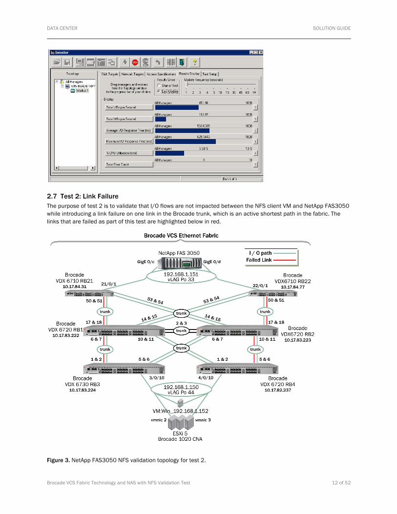
2.7 Test 2: Link Failure The purpose of test 2 is to validate that I/O flows are not impacted between the NFS client VM and NetApp FAS3050 while introducing a link failure on one link in the Brocade trunk, which is an active shortest path in the fabric. The links that are failed as part of this test are highlighted below in red.
Figure 3. NetApp FAS3050 NFS validation topology for test 2.

DATA CENTER SOLUTION GUIDE
Brocade VCS Fabric Technology and NAS with NFS Validation Test 13 of 52
The NFS clients on RB3 and RB4 continue to access the NetApp FAS3050 on the active/active vLAG interface on RB21 and RB22.
2.7.1 Test Procedure Step 1: Run Iometer on the Windows VM for the duration of the test.
Step 2: Execute the following command on the desired Brocade VDX switches to validate baseline traffic prior to failure. The following is an example:
VDX6730-RB3# show in te 3/0/1 | in rate
VDX6730-RB3# show in te 3/0/2 | in rate
Step 3: Now that active traffic on both Brocade ISLs is confirmed, an ISL in the trunk is failed. In this example, Interface TenGbE3/0/1 is failed, which is one of the active ISLs in the trunk between RB3 and RB1.
VDX6730-0 RB3(config)# in te 3/0/1 VDX6730-RB3(conf-if-te-3/0/1)# shut
Step 4: Execute the following command on the desired Brocade VDX switches to observe traffic levels after interface failure. The following is an example: VDX6730-RB3# show in te 3/0/1 | in rate
VDX6730-RB3# show in te 3/0/2 | in rate
Step 5: Execute the following command on the desired Brocade VDX switches to re-enable the failed ISL: VDX6730-RB3# conf
Entering configuration mode terminal
VDX6730-RB3(config)# in te 3/0/1
VDX6730-RB3(conf-if-te-3/0/1)# no shut
Step 6: Execute the following command on the desired Brocade VDX switches to observe traffic levels after interface re-enabling. The following is an example: VDX6730-RB3# show in te 3/0/1 | in rate
VDX6730-RB3# show in te 3/0/2 | in rate
Repeat Steps 1–6: Steps 1–6 were also performed for the other Brocade ISLs that are highlighted in red under section 2.7.
2.7.2 Expected Results The expected results for test 2 are to confirm that distributed I/O is not impacted while failing an active Brocade member ISL within the fabric.
The NFS clients on RB3 and RB4 continue to access the NetApp FAS3050 on the active/active vLAG interface on RB21 and RB22.

DATA CENTER SOLUTION GUIDE
Brocade VCS Fabric Technology and NAS with NFS Validation Test 14 of 52
All I/Os from the NFS client on RB3 and RB4 fail over to the remaining link on the Brocade trunks going into RB21 and RB22, where the active/active vLAG is located on the NFS server. Since the trunks have 20 Gbps of aggregated bandwidth, there should be no loss of throughput, unless there is more than 10 Gbps of I/O going through the fabric when a single 10 Gbps link is failed during the test. When the links in the trunk are re-enabled, the I/Os get evenly redistributed to all of the active links in the trunk.
2.7.3 Actual Results The actual results for test 2 confirm that distributed I/O is not impacted while failing an active Brocade member ISL within the fabric.
During the link failure in the Brocade trunk, while I/O was evenly distributed between the two 10 GbE links on the 20 GbE trunk, all I/O was immediately switched to the remaining 10 GbE link. When the link was re-enabled, all I/O was immediately rebalanced between both links again.
The same results were observed between other Brocade ISL trunk link failures in the fabric. These failures were performed for the other Brocade ISLs, highlighted in red under section 2.6.5. Again, there was no disruption of I/O from the perspective of the Windows VM/NFS client.
The maximum throughput of 119 MB/sec was the same before, during, and after the link failure.
2.8 Test 3: Active Path Failure The purpose of test 3 is to validate that I/O flows are not impacted between the NFS client VM and NetApp FAS3050 while introducing a complete active path failure. This is done by failing both interfaces in the Brocade trunk, which is an active shortest path in the fabric. The links that are failed as part of this test are highlighted below in red. Observe that all I/Os get rerouted via fabric switching in the remaining paths.

DATA CENTER SOLUTION GUIDE
Brocade VCS Fabric Technology and NAS with NFS Validation Test 15 of 52
Figure 4. NetApp FAS3050 NFS validation topology for test 3.
2.8.1 Test Procedure Step 1: Run Iometer on the Windows VM for the duration of the test.
Step 2: Execute the following command on RB3 to validate fabric topology prior to path failure.
VDX6730-RB3# show fabric route topology
Total Path Count: 8
Src Dst Out Out Nbr Nbr
RB-ID RB-ID Index Interface Hops Cost Index Interface BW Trunk
-----------------------------------------------------------------------------------
3 1 2 Te 3/0/2 1 500 7 Te 1/0/7 20G Yes
2 6 Te 3/0/6 1 500 7 Te 2/0/7 20G Yes
4 2 Te 3/0/2 2 1000 7 Te 1/0/7 20G Yes
4 6 Te 3/0/6 2 1000 7 Te 2/0/7 20G Yes
21 2 Te 3/0/2 2 1000 7 Te 1/0/7 20G Yes
21 6 Te 3/0/6 2 1000 7 Te 2/0/7 20G Yes
22 6 Te 3/0/6 2 1000 7 Te 2/0/7 20G Yes
22 2 Te 3/0/2 2 1000 7 Te 1/0/7 20G Yes

DATA CENTER SOLUTION GUIDE
Brocade VCS Fabric Technology and NAS with NFS Validation Test 16 of 52
In the base testing, it is known that the NFS clients on RB3 and RB4 take the shortest path to the NFS server. In the fabric topology prior to the path failure, note that total path count is 8, and from RB3 to RB1, note that the hop count is 1 and the cost is 500.
Step 3: In this example, interfaces TenGigE3/0/1 and TenGigE3/0/2 are failed, to fail the active path that includes both active ISLs in the trunk between RB3 and RB1.
VDX6730-RB3(config)# in te 3/0/1
VDX6730-RB3(conf-if-te-3/0/1)# shut
VDX6730-RB3(conf-if-te-3/0/1)# in te 3/0/2
VDX6730-RB3(conf-if-te-3/0/2)# shut
Step 4: Execute the following command on RB3 to observe fabric topology after path failure: VDX6730-RB3# show fabric route topology
Total Path Count: 5
Src Dst Out Out Nbr Nbr
RB-ID RB-ID Index Interface Hops Cost Index Interface BW Trunk
-----------------------------------------------------------------------------------
3 1 6 Te 3/0/6 2 1000 7 Te 2/0/7 20G Yes
2 6 Te 3/0/6 1 500 7 Te 2/0/7 20G Yes
4 6 Te 3/0/6 2 1000 7 Te 2/0/7 20G Yes
21 6 Te 3/0/6 2 1000 7 Te 2/0/7 20G Yes
22 6 Te 3/0/6 2 1000 7 Te 2/0/7 20G Yes
Step 5: Execute the following command on the desired Brocade VDX switches to observe traffic levels after interface failure. The following is an example: VDX6710-RB21# show interface Port-channel 33 | in rate
Step 6: Execute the following command on the desired Brocade VDX switches to re-enable the failed ISL: VDX6730-RB3# conf
Entering configuration mode terminal
VDX6730-RB3(config)# in te 3/0/1
VDX6730-RB3(conf-if-te-3/0/1)# no shut
VDX6730-RB3(config)# in te 3/0/2
VDX6730-RB3(conf-if-te-3/0/2)# no shut

DATA CENTER SOLUTION GUIDE
Brocade VCS Fabric Technology and NAS with NFS Validation Test 17 of 52
Step 7: Execute the following command on the desired Brocade VDX switches to observe traffic levels after interface re-enabling. The following is an example:
VDX6710-RB22# show interface Port-channel 33 | in rate
2.8.2 Expected Results The expected results for test 3 are to confirm that distributed I/O is not impacted while introducing a complete active path failure. It should be observed that all I/Os are rerouted via fabric switching in the remaining paths.
The NFS client on RB3 and RB4 should continue to access the NetApp FAS3050 on the active vLAG interface on RB21 and RB22. This test will show the resiliency of the fabric.
In this example, the shortest path on the left side from RB3 to RB21 will go down between RB1 and RB3. Through Brocade VCS Ethernet fabric switching, all of the I/Os are redirected through RB2 to RB1, in order to get to RB21.
2.8.3 Actual Results The actual results for test 3 confirm that distributed I/O is not impacted while introducing a complete active path failure. It is observed that all I/Os are rerouted via fabric switching in the remaining paths.
As expected, during the shortest path failure on the left side from the NFS client to the NetApp FAS3050, all I/Os were immediately switched over to the alternate path. Again, there was no disruption of I/O from the perspective of the Windows VM/NFS client.
From the perspective of the Iometer application, there were no errors, and all I/Os continued to flow through the fabric. Upon re-enabling the shortest path, all I/Os failed back to the shortest path between RB3 and RB1 without any disruption.
2.9 Test 4: Switch Failure The purpose of test 4 is to validate that I/O flows are not impacted between the NFS client VM and NetApp FAS3050 while introducing multiple switch failures in the active path of the Brocade VCS fabric. The first switch to be reloaded, RB2, is the principal switch in the Brocade VCS fabric. The second switch to be reloaded, RB3, is a switch directly connected to an active vLAG interface of the NFS client. For this test, all MACs were hashed onto the GbE 0/c of the NetApp FAS3050.

DATA CENTER SOLUTION GUIDE
Brocade VCS Fabric Technology and NAS with NFS Validation Test 18 of 52
Figure 5. NetApp FAS3050 NFS validation topology for test 4.
2.9.1 Test Procedure Step 1: Validate that all switches in the Brocade VCS fabric are up, and the shortest paths between the NFS client and the server are being used as depicted in test 1.
Step 2: Execute the following command on the desired Brocade VDX switches to validate fabric topology prior to failure:
VDX6720-RB4# show fabric route topology
Total Path Count: 8
Src Dst Out Out Nbr Nbr
RB-ID RB-ID Index Interface Hops Cost Index Interface BW Trunk
-----------------------------------------------------------------------------------
4 1 2 Te 4/0/2 1 500 10 Te 1/0/10 20G Yes
2 5 Te 4/0/5 1 500 11 Te 2/0/11 20G Yes
3 5 Te 4/0/5 2 1000 11 Te 2/0/11 20G Yes
3 2 Te 4/0/2 2 1000 10 Te 1/0/10 20G Yes

DATA CENTER SOLUTION GUIDE
Brocade VCS Fabric Technology and NAS with NFS Validation Test 19 of 52
21 2 Te 4/0/2 2 1000 10 Te 1/0/10 20G Yes
21 5 Te 4/0/5 2 1000 11 Te 2/0/11 20G Yes
22 5 Te 4/0/5 2 1000 11 Te 2/0/11 20G Yes
22 2 Te 4/0/2 2 1000 10 Te 1/0/10 20G Yes
Step 3: Execute the following command on any Brocade VDX switch to validate the existing principal switch in the fabric:
VDX6720-RB2# show fabric all
VCS Id: 1
Config Mode: Local-Only
Rbridge-id WWN IP Address Name
----------------------------------------------------------------------------
1 10:00:00:05:33:46:6A:8D 10.17.83.222 “VDX6720-RB1”
2 10:00:00:05:33:67:FE:A5 10.17.83.223 >“VDX6720-RB2”*
3 10:00:00:05:33:91:3A:E4 10.17.83.224 “VDX6730-RB3”
4 10:00:00:05:33:67:CA:BC 10.17.82.237 “VDX6720-RB4”
21 10:00:00:05:33:8C:AD:91 10.17.84.31 “VDX6710-RB21”
22 10:00:00:05:33:8C:D3:FD 10.17.84.77 “VDX6710-RB22”
The Fabric has 6 Rbridge(s)
Step 4: Run Iometer on the Windows VM for the duration of the test.
Step 5: Now that it is confirmed that the principal switch is RB2, the disabling of the RB2 switch can proceed.
VDX6720-RB2# reload
Warning: Unsaved configuration will be lost.
Are you sure you want to reload the switch? [y/n]:y
The system is going down for reload NOW !!
Broadcast message from root Wed Jan 18 18:44:57 2012...
The system is going down for reboot NOW !!
Step 6: Execute the following command on the desired Brocade VDX switches to validate the fabric topology after RB2 failure:
VDX6720-RB4# show fabric all
VCS Id: 1
Config Mode: Local-Only
Rbridge-id WWN IP Address Name
----------------------------------------------------------------------------
1 10:00:00:05:33:46:6A:8D 10.17.83.222 >“VDX6720-RB1”
3 10:00:00:05:33:91:3A:E4 10.17.83.224 “VDX6730-RB3”
4 10:00:00:05:33:67:CA:BC 10.17.82.237 “VDX6720-RB4”*

DATA CENTER SOLUTION GUIDE
Brocade VCS Fabric Technology and NAS with NFS Validation Test 20 of 52
21 10:00:00:05:33:8C:AD:91 10.17.84.31 “VDX6710-RB21”
The Fabric has 4 Rbridge(s)
Step 7: Verify that I/Os are still running after principal switch RB2 failure:
Step 8: Disable the RB3 switch.
VDX6730-RB3# reload
Warning: Unsaved configuration will be lost.
Are you sure you want to reload the switch? [y/n]:y
The system is going down for reload NOW !!
Broadcast message from root Wed Jan 18 18:51:54 2012...
The system is going down for reboot NOW !!
Step 9: Execute the following command on the desired Brocade VDX switches to validate the fabric topology after RB3 failure:
VDX6720-RB4# show fabric all
VCS Id: 1
Config Mode: Local-Only
Rbridge-id WWN IP Address Name
----------------------------------------------------------------------------
1 10:00:00:05:33:46:6A:8D 10.17.83.222 >“VDX6720-RB1”
4 10:00:00:05:33:67:CA:BC 10.17.82.237 “VDX6720-RB4”*
21 10:00:00:05:33:8C:AD:91 10.17.84.31 “VDX6710-RB21”

DATA CENTER SOLUTION GUIDE
Brocade VCS Fabric Technology and NAS with NFS Validation Test 21 of 52
The Fabric has 3 Rbridge(s)
Step 10: Verify that I/Os are still running after principal switch RB3 failure:
Step 11: Execute the following command on the desired Brocade VDX switches to observe traffic levels after interface re-enabling. The following is an example:
VDX6710-RB21# show interface port-channel 33 | in rate
2.9.3 Expected Results The expected results for test 4 are to confirm that distributed I/O is not impacted while introducing multiple switch failures within the active path of the Brocade VCS fabric. It should be observed that all I/Os are rerouted via fabric switching in the remaining paths.
During the failure of the switches in the fabric impacting both end-device vLAGs, all Iometer I/Os will continue to flow. This will show little to no disruption of I/Os during the simultaneous failure of the RB2 principal switch, as well as RB3. Since the NFS client has redundant connections on RB3 and RB4 on its vLAG, it gets continuous access to the NetApp FAS3050. In addition to that, the NetApp FAS3050 also has redundant connections on RB21 and RB22 on the vLAG. This test shows the resiliency of Brocade VCS Fabric technology and its end devices when vLAGs are used. Note that in this scenario, when the principal switch RB2 is rebooted, RB22 should also exit the fabric. When RB3 gets rebooted, there should be a total of three switches leaving the fabric, and I/O will continue to flow from the NFS client to the server.
2.9.3 Actual Results The actual results for test 4 confirm that distributed I/O is not impacted while introducing multiple switch failures in the active path of the Brocade VCS fabric. It is observed that all I/Os are rerouted via fabric switching in the remaining paths.
As expected, during the failure of the principal switches RB2 and RB3, all Iometer traffic continued to flow between the NFS client and server. Brocade VCS Ethernet fabric switching utilized all available paths between the end devices and failed over I/O within sub-second convergence times. The vLAGs between the NFS server and NFS client to the

DATA CENTER SOLUTION GUIDE
Brocade VCS Fabric Technology and NAS with NFS Validation Test 22 of 52
fabric had redundant connections without having to connect to the same physical switch. This resulted in high availability of application traffic between the NFS client and server, even during switch failures.
2.10 Test 5: vMotion with Link/Path Failure The purpose of test 5 is to validate that I/O flows were not impacted throughout the duration of a successful vMotion between ESX servers acting as NFS clients with a link/path failure.
In this test scenario, there are two 10 GbE ESX servers dual connected to both RBridges 3 and 4 to the Brocade VCS fabric with NIC Teaming/vLAG, using LACP/Port-Channels 44 and 55. There are two virtual machines between the ESX servers, one RedHat Linux Enterprise 5 and the other a Windows 2008 Server, serving as NFS clients using the NetApp FAS3050 as the VM datastore.
For the NFS server, there is 1 GbE NetApp storage that is dual connected to the Brocade VCS fabric with NIC Teaming/vLAG using LACP/Port-Channel 33. See Figure 6.

DATA CENTER SOLUTION GUIDE
Brocade VCS Fabric Technology and NAS with NFS Validation Test 23 of 52
Figure 6. NetApp FAS3050 NFS validation topology for test 5.
2.10.1 Test Procedure Step 1: Validate that all switches in the Brocade VCS fabric are up and that the shortest paths between the NFS client and server are being used as depicted in test 1.
Step 2: Execute the following command on the desired Brocade VDX switches to validate fabric topology prior to failure:
VDX6730-RB3# show fabric route topology
Total Path Count: 8
Src Dst Out Out Nbr Nbr
RB-ID RB-ID Index Interface Hops Cost Index Interface BW Trunk
-----------------------------------------------------------------------------------
3 1 2 Te 3/0/2 1 500 7 Te 1/0/7 20G Yes
2 6 Te 3/0/6 1 500 7 Te 2/0/7 20G Yes
4 6 Te 3/0/6 2 1000 7 Te 2/0/7 20G Yes
4 2 Te 3/0/2 2 1000 7 Te 1/0/7 20G Yes
21 6 Te 3/0/6 2 1000 7 Te 2/0/7 20G Yes
21 2 Te 3/0/2 2 1000 7 Te 1/0/7 20G Yes
22 6 Te 3/0/6 2 1000 7 Te 2/0/7 20G Yes
22 2 Te 3/0/2 2 1000 7 Te 1/0/7 20G Yes

DATA CENTER SOLUTION GUIDE
Brocade VCS Fabric Technology and NAS with NFS Validation Test 24 of 52
Step 3: Execute the following command on any Brocade VDX switch to validate the member RBridges in the fabric:
VDX6730-RB3# show fabric all
VCS Id: 1
Config Mode: Local-Only
Rbridge-id WWN IP Address Name
----------------------------------------------------------------------------
1 10:00:00:05:33:46:6A:8D 10.17.83.222 >“VDX6720-RB1”
2 10:00:00:05:33:67:FE:A5 10.17.83.223 “VDX6720-RB2”
3 10:00:00:05:33:91:3A:E4 10.17.83.224 “VDX6730-RB3”*
4 10:00:00:05:33:67:CA:BC 10.17.82.237 “VDX6720-RB4”
21 10:00:00:05:33:8C:AD:91 10.17.84.31 “VDX6710-RB21”
22 10:00:00:05:33:8C:D3:FD 10.17.84.77 “VDX6710-RB22”
The Fabric has 6 Rbridge(s)
Step 4: Validate the vSphere client view of the VM NFS clients and NetApp FAS3050 datastore while on ESX server #2 (on the right of the figure) before vMotion and prior to RB4 failure. Note that from the ESX server #2 on the right, vmnic2 will be disabled when RB4 is failed. This is the vSphere view prior to RB4 failure:
Step 5: On the Windows VM, send I/Os throughout the duration of the vMotion and prior to RB4 failure, using Iometer to read/write to the NFS server.

DATA CENTER SOLUTION GUIDE
Brocade VCS Fabric Technology and NAS with NFS Validation Test 25 of 52
Step 6: On the Linux VM, send I/Os before the vMotion and prior to RB4 failure, using “dd” to read/write to the NFS server.
Step 7: Begin vMotion.

DATA CENTER SOLUTION GUIDE
Brocade VCS Fabric Technology and NAS with NFS Validation Test 26 of 52
Step 8: Proceed with disabling the RB4 switch.
VDX6720-RB4# reload
Warning: Unsaved configuration will be lost.
Are you sure you want to reload the switch? [y/n]:y
The system is going down for reload NOW !!
Broadcast message from root Tue Jan 23 14:22:49 2012...
The system is going down for reboot NOW !!
Step 9: Execute the following command on the desired Brocade VDX switches to validate fabric topology after RB4 failure:
VDX6730-RB3# show fabric all
VCS Id: 1
Config Mode: Local-Only
Rbridge-id WWN IP Address Name
----------------------------------------------------------------------------
1 10:00:00:05:33:46:6A:8D 10.17.83.222 >“VDX6720-RB1”
2 10:00:00:05:33:67:FE:A5 10.17.83.223 “VDX6720-RB2”
3 10:00:00:05:33:91:3A:E4 10.17.83.224 “VDX6730-RB3”*
21 10:00:00:05:33:8C:AD:91 10.17.84.31 “VDX6710-RB21”
22 10:00:00:05:33:8C:D3:FD 10.17.84.77 “VDX6710-RB22”
The Fabric has 5 Rbridge(s)
Step 10: Execute the following command on any Brocade VDX switch to validate the member RBridges in the fabric after RB4 failure:
VDX6730-RB3# show fabric route topology
Total Path Count: 6
Src Dst Out Out Nbr Nbr
RB-ID RB-ID Index Interface Hops Cost Index Interface BW Trunk
-----------------------------------------------------------------------------------
3 1 2 Te 3/0/2 1 500 7 Te 1/0/7 20G Yes
2 6 Te 3/0/6 1 500 7 Te 2/0/7 20G Yes
21 6 Te 3/0/6 2 1000 7 Te 2/0/7 20G Yes
21 2 Te 3/0/2 2 1000 7 Te 1/0/7 20G Yes
22 6 Te 3/0/6 2 1000 7 Te 2/0/7 20G Yes
22 2 Te 3/0/2 2 1000 7 Te 1/0/7 20G Yes

DATA CENTER SOLUTION GUIDE
Brocade VCS Fabric Technology and NAS with NFS Validation Test 27 of 52
Step 11: Validate the vSphere client view of the VM NFS clients and NetApp FAS3050 datastore during RB4 failure and vMotion:
Step 12: Validate the vSphere client view of the VM NFS clients and NetApp FAS3050 datastore during RB4 failure and after successful vMotion:

DATA CENTER SOLUTION GUIDE
Brocade VCS Fabric Technology and NAS with NFS Validation Test 28 of 52
Step 13: Verify that I/Os are still running after switch RB4 failure—that the Windows VM is sending I/Os during vMotion and RB4 failure, using Iometer to read/write to the NFS server.
Step 14: Verify that I/Os are still running after switch RB4 failure—that the Linux VM is sending I/Os during vMotion and RB4 failure, using “dd” to write to the NFS server.

DATA CENTER SOLUTION GUIDE
Brocade VCS Fabric Technology and NAS with NFS Validation Test 29 of 52
2.10.2 Expected Results The expected results for test 5 are to confirm that distributed I/O is not impacted while introducing a switch failure within the active path of a Brocade VCS fabric while VM clients are sending I/Os to the NFS server; they will be moved to another ESX server using vMotion. During the vMotion, there will be a failure on RB4, but there will be no disruption of I/Os.
2.10.3 Actual Results The actual results for test 5 confirm that distributed I/O is not impacted while introducing a switch failure in the active path of the Brocade VCS fabric while VM clients are sending I/Os to the NFS server; they are moved to another ESX server using vMotion. Before, during, and after RB4 failure and vMotion of both VMs, while they were accessing the NFS server, there was no disruption of I/O. Note that one “ping” from the Windows VM was lost due to an “in-flight” frame that was lost during the failure. It was observed that all I/Os were rerouted via fabric switching in the remaining paths.

DATA CENTER SOLUTION GUIDE
Brocade VCS Fabric Technology and NAS with NFS Validation Test 30 of 52
3. TEST CASE #2: RED HAT ENTERPRISE LINUX NFS SERVER The topology used for validation is shown below. For this test, one type of NAS storage was used, with Red Hat Enterprise Linux configured as an NFS server.
Test Case #2 with Red Hat Enterprise Linux NFS server: This test consists of a 4-node Brocade VCS fabric with a Red Hat Enterprise Linux NFS server. For this test, Spirent is used as a characterization tool for NFS clients. Spirent will emulate many NFS clients accessing the Red Hat Enterprise Linux NFS server share. Each of the NFS clients mounted the NFS share of the Red Hat Enterprise Linux NFS server.
The purpose is to demonstrate that the topology of the network can change with limited implication to the application using NFS as an underlying protocol. Please note that this does not include a full configuration or validation of specific features on ESXi, Red Hat, NetApp, and VMware. Also, please note that for this test case, the NetApp FAS3050 has Gigabit Ethernet interfaces. Therefore, a Brocade VDX 6710 was used to extend Gigabit Ethernet to both RB1 and RB2. However, for most cases, it is recommended that you use redundant links for all fabric facing interfaces.
3.1 Test Case #2 Results Test Case #2 was performed successfully, with no issues. The Brocade VCS fabric interoperates with the Network File System (NFS) Protocol using Red Hat Enterprise Linux NFS server.
This validation demonstrates that existing deployments using NFS will interoperate with Brocade VCS fabrics and exhibit resiliency to input/output (I/O) between clients and servers in a non-disruptive manner.
This is a summary of the tests conducted for Test Case #2.
1. Test 1 validated that baseline I/O is using the shortest equal-cost paths in the fabric. NFS clients on RB3 and RB4 will access the Linux NFS server on the active vLAG interface on RB1.
2. Test 2 validated that I/O flows are not impacted between the NFS clients emulated by Spirent Avalanche and Red Hat Enterprise Linux NFS server while introducing a link failure on one link in the Brocade trunk, which is an active shortest path in the fabric.
3. Test 4 validated that I/O flows are not impacted between the NFS clients emulated by Spirent Avalanche and Red Hat Enterprise Linux NFS server while introducing a switch failure in the active path of the Brocade VCS fabric.
This summarizes the test results for Test Case #2.
Test Description Results
1 Baseline of shortest paths and traffic distribution in the Brocade VCS fabric
Pass
2 Perform link failure within a Brocade ISL trunk Pass
3 Perform multiple switch failures within the Brocade VCS fabric Pass

DATA CENTER SOLUTION GUIDE
Brocade VCS Fabric Technology and NAS with NFS Validation Test 31 of 52
3.2 Topology
Figure 7. Red Hat Enterprise Linux NFS server validation topology and components for Test Case #2.
3.3 Hardware Resources The following equipment was used in this configuration:
Description Quantity Revisions
Brocade VDX 6720-24 3 Brocade NOS 2.1.1
Brocade VDX 6730-32 1 Brocade NOS 2.1.1
Linux NFS Server 1 Red Hat Enterprise Linux Server Release 5.2 (Tikanga)
Spirent Avalanche 1 3.6.0
3.4 Compute Resources The following equipment was used in this configuration:
Description Quantity Revisions
Linux NFS Server 1 HP Proliant DL380G5p 320 GB HD 4 GB RAM & 1020 CNA

DATA CENTER SOLUTION GUIDE
Brocade VCS Fabric Technology and NAS with NFS Validation Test 32 of 52
3.5 Software Resources The following software was used in this configuration:
Description Revision
Brocade NOS Brocade NOS 2.1.1
Linux NFS Server Red Hat Enterprise Linux Server release 5.2 (Tikanga)
3.6 Test 1: I/O Verification The purpose of test 1 is to validate baseline I/O is using the shortest equal-cost paths in the fabric. NFS clients on RB3 and RB4 will access the Linux NFS server on the active vLAG interface on RB1.
Figure 8. Red Hat Enterprise Linux NFS server validation topology for test 1.
3.6.1 Test Procedure Step 1: Execute the following command on all Brocade VDX ISLs and VDX vLAG interfaces to confirm traffic flow and that the I/O path is distributed as expected.
The following is an example:
VDX6730-RB3# show in te 3/0/24 | in rate
Step 2: Run Spirent Test Center, which emulates the NFS clients on RB3/RB2.

DATA CENTER SOLUTION GUIDE
Brocade VCS Fabric Technology and NAS with NFS Validation Test 33 of 52
3.6.2 Expected Results The expected results for test 1 is that all I/Os from each of the NFS clients on RB3 and RB4 will be spread evenly across the Brocade trunks going into RB1, where the active vLAG on the server is located.
3.6.3 Actual Results The actual results for test 1 confirm that all I/Os from each of the NFS clients on RB3 and RB4 are spread evenly across the Brocade trunks going into RB1, where the active vLAG on the server is located.
The total bandwidth from the 95 Spirent clients on RB3 (3/0/24) and RB4 (4/0/24) are received on the Egress port going to the NFS server (1/0/23).

DATA CENTER SOLUTION GUIDE
Brocade VCS Fabric Technology and NAS with NFS Validation Test 34 of 52
3.7 Test 2: Link Failure The purpose of test 2 is to validate that I/O flows are not impacted between the NFS clients emulated by Spirent Avalanche and Red Hat Enterprise Linux NFS server while introducing a link failure on one link in the Brocade trunk, which is an active shortest path in the fabric. The links that are failed as part of this test are highlighted below in red.
Figure 9. Red Hat Enterprise Linux NFS server validation topology for test 2.
The NFS clients on RB3 and RB4 continue to access the Red Hat Enterprise Linux NFS server on the active vLAG interface on RB1.
3.7.1 Test Procedure Step 1: Execute the following command on the desired Brocade VDX switches to validate baseline traffic prior to failure. The following is an example:
VDX6730-RB3# show in te 3/0/1 | in rate
VDX6730-RB3# show in te 3/0/2 | in rate
Step 2: Run Spirent Avalanche for the duration of the test to emulate the NFS clients.
Step 3: Now that active traffic on both Brocade ISLs is confirmed, an ISL in the trunk is failed. In this example, Interface TenGigE3/0/1 on RB3 is failed, which is one of the active ISLs in the trunk between RB3 and RB1.
VDX6730-RB3# conf t
Entering configuration mode terminal
VDX6730-RB3(config)# in te 3/0/1
VDX6730-RB3(conf-if-te-3/0/1)# shut

DATA CENTER SOLUTION GUIDE
Brocade VCS Fabric Technology and NAS with NFS Validation Test 35 of 52
Step 4: Execute the following command on the desired Brocade VDX switches to observe traffic levels after interface failure. The following is an example: VDX6730-RB3# show in te 3/0/1 | in rate
VDX6730-RB3# show in te 3/0/2 | in rate
Step 5: Execute the following command on the desired Brocade VDX switches to re-enable the failed ISL between RB3 and RB1. VDX6730-RB3# conf t
Entering configuration mode terminal
VDX6730-RB3(config)# in te 3/0/1
VDX6730-RB3(conf-if-te-3/0/1)# no shut
Step 6: Execute the following command on the desired Brocade VDX switches to observe traffic levels after interface re-enabling. The following is an example: VDX6730-RB3# show in te 3/0/1 | in rate
VDX6730-RB3# show in te 3/0/2 | in rate
Repeat Steps 1–6: Steps 1–6 were also performed for the other Brocade ISLs, highlighted in red under section 3.5.1.
3.7.2 Expected Results The expected results for test 2 are to confirm that distributed I/O is not impacted while failing an active Brocade member ISL within the fabric.
The NFS clients on RB3 and RB4 continue to access the Red Hat Enterprise Linux NFS server on the active vLAG interface on RB1.
All I/Os from each of the NFS clients on RB3 and RB4 fail over to the remaining link on the Brocade trunk that goes into RB1, where the active vLAG on the server is located. The total bandwidth from the clients on RB3 (3/0/24) and RB4 (4/0/24) are received on the Egress port going to the NFS server (1/0/23). There should be no loss in I/O, with the exception of “in-flight” frames during the failure of the link. When the links in the trunk are re-enabled, the I/Os should be evenly redistributed to all of the active links in the trunk.
The same results should be observed between other Brocade ISL trunk link failures in the fabric. These failures were performed for the other Brocade ISLs highlighted in red under section 3.5.1.
3.7.3 Actual Results The actual results for test 2 confirm that distributed I/O is not impacted while failing an active Brocade member ISL within the fabric.
During the link failure in the Brocade trunk while I/O was evenly distributed between the two 10 GbE links on the 20 GbE trunk; all I/O was immediately switched to the remaining 10 GbE link. When the link was re-enabled, all I/O was immediately rebalanced between both links again.
The same results were observed between other Brocade ISL trunk link failures in the fabric. These failures were performed for the other Brocade ISLs highlighted in red under section 3.5.1. Again, there was no disruption of I/O from the perspective of the Windows VM/NFS client.

DATA CENTER SOLUTION GUIDE
Brocade VCS Fabric Technology and NAS with NFS Validation Test 36 of 52
All I/Os from each of the NFS clients on RB3 and RB4 fail over to the remaining link on the Brocade trunk that goes into RB1, where the active vLAG on the server is located. The total bandwidth from the clients on RB3 (3/0/24) and RB4 (4/0/24) are received on the Egress port going to the NFS server (1/0/23).
When the links in the trunk are re-enabled, the I/O is evenly redistributed to all of the active links in the trunk.
It appears that there was a loss of “in-flight” NFS frames during the failure, as highlighted in the output below.
3.8 Test 3: Switch Failure The purpose of test 3 is to validate that I/O flows are not impacted between the NFS clients emulated by Spirent Avalanche and Red Hat Enterprise Linux NFS server, while introducing a switch failure in the active path of the Brocade VCS fabric. The switch to be reloaded, RB1, is a switch directly connected to an active vLAG interface of the Red Hat Enterprise Linux NFS server.

DATA CENTER SOLUTION GUIDE
Brocade VCS Fabric Technology and NAS with NFS Validation Test 37 of 52
Figure 10. Red Hat Enterprise Linux NFS server validation topology for test 3.
3.8.1 Test Procedure Step 1: Validate that all switches in the Brocade VCS fabric are up and that the shortest paths between the NFS client and server are being used as depicted in test 1.
Step 2: Execute the following command on the desired Brocade VDX switches to validate baseline traffic prior to failure. The following is an example:
VDX6730-RB3# show in te 3/0/24 | in rate
VDX6720-RB2# show in te 2/0/23 | in rate
Step 3: Execute the following command on the desired Brocade VDX switches to validate fabric topology prior to failure:
VDX6730-RB3# show fabric route topology
Total Path Count: 6
Src Dst Out Out Nbr Nbr
RB-ID RB-ID Index Interface Hops Cost Index Interface BW Trunk
-----------------------------------------------------------------------------------
3 1 1 Te 3/0/1 1 500 6 Te 1/0/6 20G Yes
2 5 Te 3/0/5 1 500 6 Te 2/0/6 20G Yes
4 5 Te 3/0/5 2 1000 6 Te 2/0/6 20G Yes
4 1 Te 3/0/1 2 1000 6 Te 1/0/6 20G Yes
21 1 Te 3/0/1 2 1000 6 Te 1/0/6 20G Yes
22 5 Te 3/0/5 2 1000 6 Te 2/0/6 20G Yes

DATA CENTER SOLUTION GUIDE
Brocade VCS Fabric Technology and NAS with NFS Validation Test 38 of 52
VDX6720-RB4# show fabric route topology
Total Path Count: 6
Src Dst Out Out Nbr Nbr
RB-ID RB-ID Index Interface Hops Cost Index Interface BW Trunk
-----------------------------------------------------------------------------------
4 1 1 Te 4/0/1 1 500 11 Te 1/0/11 20G Yes
2 6 Te 4/0/6 1 500 10 Te 2/0/10 20G Yes
3 6 Te 4/0/6 2 1000 10 Te 2/0/10 20G Yes
3 1 Te 4/0/1 2 1000 11 Te 1/0/11 20G Yes
21 1 Te 4/0/1 2 1000 11 Te 1/0/11 20G Yes
22 6 Te 4/0/6 2 1000 10 Te 2/0/10 20G Yes
Note that all shortest paths are active, and there are six switches in the fabric.
Step 4: Disable RB1 to simulate switch failure, forcing the vLAG to use the standby link on RB2 to the NFS server.
VDX6720-RB1# reload
Warning: Unsaved configuration will be lost.
Are you sure you want to reload the switch? [y/n]:y
The system is going down for reload NOW !!
Broadcast message from root Thu Dec 22 00:04:10 2011...
The system is going down for reboot NOW !!
Step 5: Execute the following command on the desired Brocade VDX switches to validate fabric topology after RB1 failure:
VDX6730-RB3# show fabric route topology
Total Path Count: 3
Src Dst Out Out Nbr Nbr
RB-ID RB-ID Index Interface Hops Cost Index Interface BW Trunk
-----------------------------------------------------------------------------------
3 2 5 Te 3/0/5 1 500 6 Te 2/0/6 20G Yes
4 5 Te 3/0/5 2 1000 6 Te 2/0/6 20G Yes
22 5 Te 3/0/5 2 1000 6 Te 2/0/6 20G Yes

DATA CENTER SOLUTION GUIDE
Brocade VCS Fabric Technology and NAS with NFS Validation Test 39 of 52
VDX6720-RB4# show fabric route topology
Total Path Count: 3
Src Dst Out Out Nbr Nbr
RB-ID RB-ID Index Interface Hops Cost Index Interface BW Trunk
-----------------------------------------------------------------------------------
4 2 6 Te 4/0/6 1 500 10 Te 2/0/10 20G Yes
3 6 Te 4/0/6 2 1000 10 Te 2/0/10 20G Yes
22 6 Te 4/0/6 2 1000 10 Te 2/0/10 20G Yes
Step 6: Verify that I/Os are still running after principal switch RB2 failure. The previous standby vLAG link to the NFS server on RB2 is now the active link (Egress to NFS server). The following is an example: VDX6720-RB2# show in te 2/0/23 | in rate
Step 7: Execute the following command on the desired Brocade VDX switches to validate fabric topology after RB1 has become active:
VDX6730-RB3# show fabric route topology
Total Path Count: 6
Src Dst Out Out Nbr Nbr
RB-ID RB-ID Index Interface Hops Cost Index Interface BW Trunk
-----------------------------------------------------------------------------------
3 1 1 Te 3/0/1 1 500 6 Te 1/0/6 20G Yes
2 5 Te 3/0/5 1 500 6 Te 2/0/6 20G Yes
4 5 Te 3/0/5 2 1000 6 Te 2/0/6 20G Yes
4 1 Te 3/0/1 2 1000 6 Te 1/0/6 20G Yes
21 1 Te 3/0/1 2 1000 6 Te 1/0/6 20G Yes
22 5 Te 3/0/5 2 1000 6 Te 2/0/6 20G Yes
VDX6720-RB4# show fabric route topology
Total Path Count: 6
Src Dst Out Out Nbr Nbr
RB-ID RB-ID Index Interface Hops Cost Index Interface BW Trunk
-----------------------------------------------------------------------------------
4 1 1 Te 4/0/1 1 500 11 Te 1/0/11 20G Yes
2 6 Te 4/0/6 1 500 10 Te 2/0/10 20G Yes
3 6 Te 4/0/6 2 1000 10 Te 2/0/10 20G Yes
3 1 Te 4/0/1 2 1000 11 Te 1/0/11 20G Yes
21 1 Te 4/0/1 2 1000 11 Te 1/0/11 20G Yes
22 6 Te 4/0/6 2 1000 10 Te 2/0/10 20G Yes

DATA CENTER SOLUTION GUIDE
Brocade VCS Fabric Technology and NAS with NFS Validation Test 40 of 52
3.8.2 Expected Results The expected results for test 3 are to confirm that distributed I/O is not impacted while introducing a switch failure within the active path of the Brocade VCS fabric. It should be observed that all I/Os are rerouted via fabric switching in the remaining paths.
During the failure of the switches in the fabric impacting both end-device vLAGs, all Spirent client sessions will continue to flow. This will show little to no disruption of I/Os during the failure of RB1. Since the Spirent NFS server has redundant connections on RB1 and RB2 on its vLAG, it gets continuous access to the Spirent NFS clients. This test should show the resiliency of Brocade VCS Fabric technology and its end devices when vLAGs are used.
3.8.3 Actual Results The actual results for test 3 confirm that distributed I/O is not impacted while introducing multiple switch failures in the active path of the Brocade VCS fabric. It is observed that all Spirent NFS clients are rerouted via fabric switching in the remaining paths.
As expected, during the switch failure of RB1, all Spirent client sessions continued to flow to the NFS server. Brocade VCS Ethernet fabric switching utilized all available paths between the end devices and failed over within sub-second convergence times. This test shows the resiliency of Brocade VCS fabric technology and its end devices when vLAGs are used.

DATA CENTER SOLUTION GUIDE
Brocade VCS Fabric Technology and NAS with NFS Validation Test 41 of 52
APPENDIX A: TEST CASE #1
Brocade VCS Deployment Considerations: Dynamic LACP vLAG with NetApp
Step 1: Configure vLAG Port-channel Interface on Brocade VDX 6710-RB21 to NetApp FAS3050 GbE 0/c:
VDX6710-RB21# conf t
Entering configuration mode terminal
VDX6710-RB21(config)# interface Port-channel 33
VDX6710-RB21(config-Port-channel-33)# vlag ignore-split
VDX6710-RB21(config-Port-channel-33)# speed 1000
VDX6710-RB21(config-Port-channel-33)# description NetApp3050-VDX
VDX6710-RB21(config-Port-channel-33)# switchport
VDX6710-RB21(config-Port-channel-33)# switchport mode access
VDX6710-RB21(config-Port-channel-33)# switchport access vlan 1
VDX6710-RB21(config-Port-channel-33)# no shutdown
Step 2: Configure Interface Gigabit Ethernet 21/0/1 on Brocade VDX6710-RB21:
VDX6710-RB21# conf t
Entering configuration mode terminal
VDX6710-RB21(config)# interface GigabitEthernet 21/0/1
VDX6710-RB21(conf-if-gi-21/0/1)# description NetApp3050_e0c
VDX6710-RB21(conf-if-gi-21/0/1)# channel-group 33 mode active type standard
VDX6710-RB21(conf-if-gi-21/0/1)# lacp timeout long
VDX6710-RB21(conf-if-gi-21/0/1)# no shutdown
Step 3: Configure vLAG Port-channel Interface on Brocade VDX 6710-RB22 to NetApp FAS3050 GbE 0/d:
VDX6710-RB22# conf t
Entering configuration mode terminal
VDX6710-RB22(config)# interface Port-channel 33
VDX6710-RB22(config-Port-channel-33)# vlag ignore-split
VDX6710-RB22(config-Port-channel-33)# speed 1000
VDX6710-RB22(config-Port-channel-33)# description NetApp3050-VDX
VDX6710-RB22(config-Port-channel-33)# switchport
VDX6710-RB22(config-Port-channel-33)# switchport mode access
VDX6710-RB22(config-Port-channel-33)# switchport access vlan 1
VDX6710-RB22(config-Port-channel-33)# no shutdown
Step 4: Configure Interface Gigabit Ethernet 22/0/1 on Brocade VDX6710-RB22:
VDX6710-RB22# conf t
Entering configuration mode terminal
VDX6710-RB22(config)# interface GigabitEthernet 22/0/1
VDX6710-RB22(conf-if-gi-22/0/1)# channel-group 33 mode active type standard
VDX6710-RB22(conf-if-gi-22/0/1)# lacp timeout long
VDX6710-RB22(conf-if-gi-22/0/1)# no shutdown

DATA CENTER SOLUTION GUIDE
Brocade VCS Fabric Technology and NAS with NFS Validation Test 42 of 52
Step 5: Validate vLAG Port-channel Interface on Brocade VDX 6710-RB21 to NetApp FAS3050 GbE 0/c:
VDX6710-RB21# show interface Port-channel 33
Port-channel 33 is up, line protocol is up
Hardware is AGGREGATE, address is 0005.338c.adee
Current address is 0005.338c.adee
Description: NetApp3050-VDX
Interface index (ifindex) is 671088673
Minimum number of links to bring Port-channel up is 1
MTU 2500 bytes
LineSpeed Actual : 1000 Mbit
Allowed Member Speed : 1000 Mbit
Step 6: Validate Interface Gigabit Ethernet 22/0/1 on Brocade VDX6710-RB22:
VDX6710-RB21# show interface gigabitethernet 21/0/1
GigabitEthernet 21/0/1 is up, line protocol is up (connected)
Hardware is Ethernet, address is 0005.338c.adb6
Current address is 0005.338c.adb6
Fixed Copper RJ45 Media Present
Description: NetApp3050_e0c
Interface index (ifindex) is 90597048320
MTU 2500 bytes
LineSpeed : 1000 Mbit, Duplex: Full
Flowcontrol rx: off, tx: off
Step 7: Validate vLAG Port-channel Interface on Brocade VDX 6710-RB21 to NetApp FAS3050 GbE 0/c:
VDX6710-RB22# show interface Port-channel 33
Port-channel 33 is up, line protocol is up
Hardware is AGGREGATE, address is 0005.338c.d45a
Current address is 0005.338c.d45a
Description: NetApp3050-VDX
Interface index (ifindex) is 671088673
Minimum number of links to bring Port-channel up is 1
MTU 2500 bytes
LineSpeed Actual : 1000 Mbit
Allowed Member Speed : 1000 Mbit
Flowcontrol rx: off, tx: off
Step 8: Validate Interface Gigabit Ethernet 22/0/1 on Brocade VDX6710-RB22:
VDX6710-RB22# show interface gigabitethernet 22/0/1
GigabitEthernet 22/0/1 is up, line protocol is up (connected)
Hardware is Ethernet, address is 0005.338c.d422
Current address is 0005.338c.d422
Fixed Copper RJ45 Media Present
Interface index (ifindex) is 94892015616
MTU 2500 bytes
LineSpeed : 1000 Mbit, Duplex: Full
Flowcontrol rx: off, tx: off

DATA CENTER SOLUTION GUIDE
Brocade VCS Fabric Technology and NAS with NFS Validation Test 43 of 52
Brocade VDX Deployment Considerations: Static LACP vLAG with ESXi Server and Brocade 1020 CNA Step 1: Configure vLAG Port-channel Interface on Brocade VDX 6730-RB3 to ESXi5-vswitch1:
VDX6730-RB3# conf t
Entering configuration mode terminal
VDX6730-RB3(config)# interface Port-channel 44
VDX6730-RB3(config-Port-channel-44)# vlag ignore-split
VDX6730-RB3(config-Port-channel-44)# description ESXi5-vSwitch1
VDX6730-RB3(config-Port-channel-44)# switchport
VDX6730-RB3(config-Port-channel-44)# switchport mode access
VDX6730-RB3(config-Port-channel-44)# switchport access vlan 1
VDX6730-RB3(config-Port-channel-44)# no shutdown
Step 2: Configure Interface TenGigabit Ethernet 3/0/10 on Brocade VDX6720-RB3:
VDX6730-RB3# conf t
Entering configuration mode terminal
VDX6730-RB3(config)# interface TenGigabitEthernet 3/0/10
VDX6730-RB3(conf-if-te-3/0/10)# description ESXi5-vmnic2
VDX6730-RB3(conf-if-te-3/0/10)# channel-group 44 mode on type standard
VDX6730-RB3(conf-if-te-3/0/10)# no shutdown
Step 3: Configure vLAG Port-channel Interface on Brocade VDX 6720-RB4 to ESXi5-vswitch1:
VDX6720-RB4# conf t
Entering configuration mode terminal
VDX6720-RB4(config)# interface Port-channel 44
VDX6720-RB4(config-Port-channel-44)# vlag ignore-split
VDX6720-RB4(config-Port-channel-44)# description ESXi5-vSwitch1
VDX6720-RB4(config-Port-channel-44)# switchport
VDX6720-RB4(config-Port-channel-44)# switchport mode access
VDX6720-RB4(config-Port-channel-44)# switchport access vlan 1
VDX6720-RB4(config-Port-channel-44)# no shutdown
Step 4: Configure Interface TenGigabit Ethernet 4/0/10 on Brocade VDX6720-RB4:
VDX6720-RB4# conf t
Entering configuration mode terminal
VDX6720-RB4(config)# interface TenGigabitEthernet 4/0/10
VDX6720-RB4(conf-if-te-4/0/10)# description ESXi5-vmnic3
VDX6720-RB4(conf-if-te-4/0/10)# channel-group 44 mode on type standard
VDX6720-RB4(conf-if-te-4/0/10)# no shutdown

DATA CENTER SOLUTION GUIDE
Brocade VCS Fabric Technology and NAS with NFS Validation Test 44 of 52
Step 5: Validate vLAG Port-channel Interface on Brocade VDX 6730-RB3 to to ESXi5-vswitch1:
VDX6730-RB3# show interface Port-channel 44
Port-channel 44 is up, line protocol is up
Hardware is AGGREGATE, address is 0005.3391.3b24
Current address is 0005.3391.3b24
Description: ESXi5-vSwitch1
Interface index (ifindex) is 671088684
Minimum number of links to bring Port-channel up is 1
MTU 2500 bytes
LineSpeed Actual : 10000 Mbit
Allowed Member Speed : 10000 Mbit
Flowcontrol rx: off, tx: off
Step 6: Validate Interface TenGigabit Ethernet 3/0/10 on Brocade VDX6730-RB3:
VDX6730-RB3# show interface tengigabitethernet 3/0/10
TenGigabitEthernet 3/0/10 is up, line protocol is up (connected)
Hardware is Ethernet, address is 0005.3391.3b12
Current address is 0005.3391.3b12
Pluggable media present
Description: ESXi5-vmnic2
Interface index (ifindex) is 13288210441
MTU 2500 bytes
LineSpeed Actual : 10000 Mbit
LineSpeed Configured : Auto, Duplex: Full
Flowcontrol rx: off, tx: off
Step 7: Validate vLAG Port-channel Interface on Brocade VDX 6720-RB4 to to ESXi5-vswitch1:
VDX6720-RB4# show interface Port-channel 44
Port-channel 44 is up, line protocol is up
Hardware is AGGREGATE, address is 0005.3367.cafc
Current address is 0005.3367.cafc
Description: ESXi5-vSwitch1
Interface index (ifindex) is 671088684
Minimum number of links to bring Port-channel up is 1
MTU 2500 bytes
LineSpeed Actual : 10000 Mbit
Allowed Member Speed : 10000 Mbit
Flowcontrol rx: off, tx: off
Step 8: Validate Interface TenGigabit Ethernet 4/0/10 on Brocade VDX6720-RB4:
VDX6720-RB4# show interface tengigabitethernet 4/0/10
TenGigabitEthernet 4/0/10 is up, line protocol is up (connected)
Hardware is Ethernet, address is 0005.3367.caea
Current address is 0005.3367.caea
Pluggable media present
Description: ESXi5-vmnic3

DATA CENTER SOLUTION GUIDE
Brocade VCS Fabric Technology and NAS with NFS Validation Test 45 of 52
Interface index (ifindex) is 17583177737
MTU 2500 bytes
LineSpeed Actual : 10000 Mbit
LineSpeed Configured : Auto, Duplex: Full
Flowcontrol rx: off, tx: off
Brocade VCS Deployment Considerations: Enable Brocade VDX Jumbo Frame Support Note that this must be performed on all RBbridges where a given interface port-channel is located. In this example, interface port-channel 44 is on RBridge 3 and RBridge 4, so we will apply configurations from both RBridge 3 and RBridge 4.
Step 1: Example to enable Jumbo Frame Support on applicable VDX interfaces for which Jumbo Frame support is required:
VDX6730-RB3# conf t
Entering configuration mode terminal
VDX6730-RB3(config)# interface Port-channel 44
VDX6730-RB3(config-Port-channel-44)# mtu
(<NUMBER:1522-9216>) (9216): 9216
Brocade VCS Deployment Considerations: Enable Ethernet Pause/Flow Control Support Note that this must be performed on all RBbridges where a given interface port-channel is located. In this example, interface port-channel 44 is on RBridge 3 and RBridge 4, so we will apply from both RBridges.
Step 1: Enable QOS Flow Control for both tx and rx on vLAG Port-channel 44 Interface of VDX 6730-RB4 to ESXi5-vswitch1:
VDX6730-RB3# conf t
Entering configuration mode terminal
VDX6730-RB3(config)# interface Port-channel 44
VDX6730-RB3(config-Port-channel-44)# qos flowcontrol tx on rx on
Step 2: Validate vLAG Port-channel 44 Interface qos rcv-queue on Brocade VDX 6730-RB4 to to ESXi5-vswitch1 after changes have been made:
VDX6730-RB3(config-Port-channel-44)# do show running-config interface Port-channel 44
interface Port-channel 44
vlag ignore-split
description ESXi5-vSwitch1
switchport
switchport mode access
switchport access vlan 1
qos flowcontrol tx on rx on
no shutdown
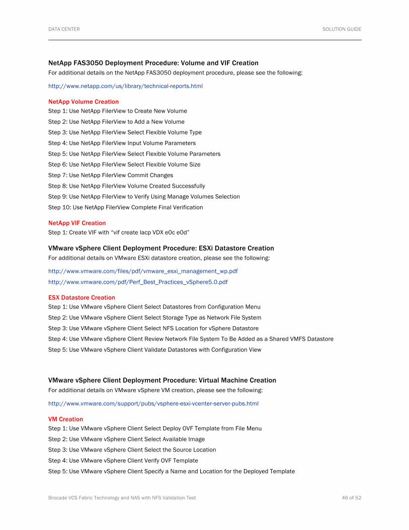
DATA CENTER SOLUTION GUIDE
Brocade VCS Fabric Technology and NAS with NFS Validation Test 46 of 52
NetApp FAS3050 Deployment Procedure: Volume and VIF Creation For additional details on the NetApp FAS3050 deployment procedure, please see the following:
http://www.netapp.com/us/library/technical-reports.html
NetApp Volume Creation Step 1: Use NetApp FilerView to Create New Volume
Step 2: Use NetApp FilerView to Add a New Volume
Step 3: Use NetApp FilerView Select Flexible Volume Type
Step 4: Use NetApp FilerView Input Volume Parameters
Step 5: Use NetApp FilerView Select Flexible Volume Parameters
Step 6: Use NetApp FilerView Select Flexible Volume Size
Step 7: Use NetApp FilerView Commit Changes
Step 8: Use NetApp FilerView Volume Created Successfully
Step 9: Use NetApp FilerView to Verify Using Manage Volumes Selection
Step 10: Use NetApp FilerView Complete Final Verification
NetApp VIF Creation Step 1: Create VIF with “vif create lacp VDX e0c e0d”
VMware vSphere Client Deployment Procedure: ESXi Datastore Creation For additional details on VMware ESXi datastore creation, please see the following:
http://www.vmware.com/files/pdf/vmware_esxi_management_wp.pdf
http://www.vmware.com/pdf/Perf_Best_Practices_vSphere5.0.pdf
ESX Datastore Creation Step 1: Use VMware vSphere Client Select Datastores from Configuration Menu
Step 2: Use VMware vSphere Client Select Storage Type as Network File System
Step 3: Use VMware vSphere Client Select NFS Location for vSphere Datastore
Step 4: Use VMware vSphere Client Review Network File System To Be Added as a Shared VMFS Datastore
Step 5: Use VMware vSphere Client Validate Datastores with Configuration View
VMware vSphere Client Deployment Procedure: Virtual Machine Creation For additional details on VMware vSphere VM creation, please see the following:
http://www.vmware.com/support/pubs/vsphere-esxi-vcenter-server-pubs.html
VM Creation Step 1: Use VMware vSphere Client Select Deploy OVF Template from File Menu
Step 2: Use VMware vSphere Client Select Available Image
Step 3: Use VMware vSphere Client Select the Source Location
Step 4: Use VMware vSphere Client Verify OVF Template
Step 5: Use VMware vSphere Client Specify a Name and Location for the Deployed Template

DATA CENTER SOLUTION GUIDE
Brocade VCS Fabric Technology and NAS with NFS Validation Test 47 of 52
Step 6: Use VMware vSphere Client Select Location of the Virtual Machine Files
Step 7: Use VMware vSphere Client Select the Format for the Virtual Disks
Step 8: Use VMware vSphere Client Map Networks Used in the OVF Template to Networks in the Inventory
Step 9: Use VMware vSphere Client Finish the OVF Template
Step 10: Use VMware vSphere Client Deployment Completed Successfully
Step 11: Use VMware vSphere Client Verify Summary
VMware ESXi Deployment Procedure: NIC Teaming for vSwitch For additional details on VMware ESXi NIC teaming for vSwitch, please see the following:
http://www.vmware.com/files/pdf/virtual_networking_concepts.pdf
http://www.vmware.com/pdf/Perf_Best_Practices_vSphere5.0.pdf
VMware ESXi NIC Teaming for vSwitch Step 1: Use VMware vSphere Client
Step 2: Use VMware vSphere Client
Step 3: Use VMware vSphere Client Select VMkernel for Networking Hardware
Step 4: Use VMware vSphere Client Create a vSphere Standard Switch
Step 5: Use VMware vSphere Client Complete VMkernel Connection Settings
Step 6: Use VMware vSphere Client Complete VMkernel IP Connection Settings
Step 7: Use VMware vSphere Client Verify vSphere Standard Switches are Configured
Step 8: Use VMware vSphere Client Select Standard vSwitch1
Step 9: Use VMware vSphere Client Select Properties for Standard vSwitch1
Step 10: Use VMware vSphere Client Edit vSwitch Properties
Step 11: Use VMware vSphere Client Select NIC Teaming
Step 12: Use VMware vSphere Client Select Route Based on IP Hash for Load Balancing

DATA CENTER SOLUTION GUIDE
Brocade VCS Fabric Technology and NAS with NFS Validation Test 48 of 52
APPENDIX B: TEST CASE #2
Brocade VCS Fabric Configuration: Static LACP vLAG with Red Hat Enterprise Linux NFS Server and Brocade 1020 CNA Step 1: Configure vLAG Port-channel Interface on Brocade VDX 6720-RB1 to Red Hat Enterprise Linux NFS Server TenGig Eth 4:
VDX6720-RB1# conf t
Entering configuration mode terminal
VDX6720-RB1(config)# interface Port-channel 11
VDX6720-RB1(config-Port-channel-11)# vlag ignore-split
VDX6720-RB1(config-Port-channel-11)# speed 1000
VDX6720-RB1(config-Port-channel-11)# description Linux-NFS-Server-bond0
VDX6720-RB1(config-Port-channel-11)# switchport
VDX6720-RB1(config-Port-channel-11)# switchport mode access
VDX6720-RB1(config-Port-channel-11)# switchport access vlan 1
VDX6720-RB1(config-Port-channel-11)# no shutdown
Step 2: Configure Interface TenGigabit Ethernet 1/0/23 on Brocade VDX6720-RB1:
VDX6720-RB1# conf t
Entering configuration mode terminal
VDX6720-RB1(config)# interface TenGigabitEthernet 1/0/23
VDX6720-RB1(conf-if-te-1/0/23)# description Linux-NFS-Server-eth4
VDX6720-RB1(conf-if-te-1/0/23)# channel-group 11 mode on type standard
VDX6720-RB1(conf-if-te-1/0/23)# no shutdown
Step 3: Configure vLAG Port-channel Interface on Brocade VDX 6720-RB2 to Redhat Linux TenGig Eth 5:
VDX6720-RB2# conf t
Entering configuration mode terminal
VDX6720-RB2(config)# interface Port-channel 11
VDX6720-RB2(config-Port-channel-11)# vlag ignore-split
VDX6720-RB2(config-Port-channel-11)# description Linux-NFS-Server-bond0
VDX6720-RB2(config-Port-channel-11)# switchport
VDX6720-RB2(config-Port-channel-11)# switchport mode access
VDX6720-RB2(config-Port-channel-11)# switchport access vlan 1
VDX6720-RB2(config-Port-channel-11)# no shutdown
Step 4: Configure Interface TenGigabit Ethernet 2/0/23 on Brocade VDX6720-RB2:
VDX6720-RB2# conf t
Entering configuration mode terminal
VDX6720-RB2(config)# interface TenGigabitEthernet 2/0/23
VDX6720-RB2(conf-if-te-2/0/23)# description Linux-NFS-Server-eth5
VDX6720-RB2(conf-if-te-2/0/23)# channel-group 11 mode on type standard
VDX6720-RB2(conf-if-te-2/0/23)# no shutdown

DATA CENTER SOLUTION GUIDE
Brocade VCS Fabric Technology and NAS with NFS Validation Test 49 of 52
Step 5: Validate vLAG Port-channel Interface on Brocade VDX 6720-RB1 to Redhat Linux TenGig Eth 4:
VDX6720-RB1# show interface Port-channel 11
Port-channel 11 is up, line protocol is up
Hardware is AGGREGATE, address is 0005.3346.6ad0
Current address is 0005.3346.6ad0
Description: Linux-NFS-Server-bond0
Interface index (ifindex) is 671088651
Minimum number of links to bring Port-channel up is 1
MTU 2500 bytes
LineSpeed Actual : 10000 Mbit
Allowed Member Speed : 10000 Mbit
Flowcontrol rx: off, tx: off
Step 6: Validate Interface TenGigabit Ethernet 1/0/23 on Brocade VDX6720-RB1:
VDX6720-RB1# show interface tengigabitethernet 1/0/23
TenGigabitEthernet 1/0/23 is up, line protocol is up (connected)
Hardware is Ethernet, address is 0005.3346.6ac8
Current address is 0005.3346.6ac8
Pluggable media present
Description: Linux-NFS-Server-eth4
Interface index (ifindex) is 4699127830
MTU 2500 bytes
LineSpeed Actual : 10000 Mbit
LineSpeed Configured : Auto, Duplex: Full
Flowcontrol rx: off, tx: off
Step 7: Validate vLAG Port-channel Interface on Brocade VDX 6720-RB20 to Redhat Linux TenGig Eth 5:
VDX6720-RB2# show interface Port-channel 11
Port-channel 11 is up, line protocol is up
Hardware is AGGREGATE, address is 0005.3367.fee8
Current address is 0005.3367.fee8
Description: Linux-NFS-Server-bond0
Interface index (ifindex) is 671088651
Minimum number of links to bring Port-channel up is 1
MTU 2500 bytes
LineSpeed Actual : 10000 Mbit
Allowed Member Speed : 10000 Mbit
Flowcontrol rx: off, tx: off
Flowcontrol rx: off, tx: off
Step 8: Validate Interface Gigabit Ethernet 2/0/23 on Brocade VDX6720-RB2:
VDX6720-RB2# show interface tengigabitethernet 2/0/23
TenGigabitEthernet 2/0/23 is up, line protocol is up (connected)
Hardware is Ethernet, address is 0005.3367.fee0
Current address is 0005.3367.fee0
Pluggable media present
Description: Linux-NFS-Server-eth5

DATA CENTER SOLUTION GUIDE
Brocade VCS Fabric Technology and NAS with NFS Validation Test 50 of 52
Interface index (ifindex) is 8994095126
MTU 2500 bytes
LineSpeed Actual : 10000 Mbit
LineSpeed Configured : Auto, Duplex: Full
Flowcontrol rx: off, tx: off
Red Hat Enterprise Linux NFS Server: NIC Bonding Configuration For additional details on Red Hat Enterprise Linux NIC bonding, please see the following:
http://docs.redhat.com/docs/en-US/Red_Hat_Enterprise_Linux/6/html/Deployment_Guide/sec-Using_Channel_Bonding.html
Step 1: Validate Red Hat release:
# cat /etc/redhat-release Red Hat Enterprise Linux Server release 5.2 (Tikanga)
Step 2: Append ifcfg-bond0:
# vi /etc/sysconfig/network-scripts/ifcfg-bond0 Append the following linest: DEVICE=bond0 IPADDR=192.168.1.20 NETWORK=192.168.1.0 NETMASK=255.255.255.0 USERCTL=no BOOTPROTO=none ONBOOT=yes
Step 3: Append ifcfg-eth4:
# vi /etc/sysconfig/network-scripts/ifcfg-eth4 Modify/append directive as follows: DEVICE=eth4 USERCTL=no ONBOOT=yes MASTER=bond0 SLAVE=yes BOOTPROTO=none
Step 4: Append ifcfg-eth5:
# vi /etc/sysconfig/network-scripts/ifcfg-eth5 Modify/append directive as follows: DEVICE=eth5 USERCTL=no ONBOOT=yes MASTER=bond0 SLAVE=yes BOOTPROTO=none

DATA CENTER SOLUTION GUIDE
Brocade VCS Fabric Technology and NAS with NFS Validation Test 51 of 52
Step 5: Append modprobe.conf:
# vi /etc/modprobe.conf Append following two lines:alias bond0 bonding options bond0 mode=balance-alb miimon=100
Step 6: Service network restart
# modprobe bonding # service network restart
Step 7: Verify bond0:
# ifconfig bond0 bond0 Link encap:Ethernet HWaddr 8C:7C:FF:0A:EB:00 inet addr:192.168.1.2 Bcast:192.168.1.255 Mask:255.255.255.0 inet6 addr: fe80::8e7c:ffff:fe0a:eb00/64 Scope:Link UP BROADCAST RUNNING MASTER MULTICAST MTU:1500 Metric:1 RX packets:93651 errors:0 dropped:0 overruns:0 frame:0 TX packets:52213 errors:0 dropped:0 overruns:0 carrier:0 collisions:0 txqueuelen:0 RX bytes:70915327 (67.6 MiB) TX bytes:18760904 (17.8 MiB)
Step 8: Verify eth4/eth5:
# ifconfig eth4 eth4 Link encap:Ethernet HWaddr 8C:7C:FF:0A:EB:00 inet6 addr: fe80::8e7c:ffff:fe0a:eb00/64 Scope:Link UP BROADCAST RUNNING SLAVE MULTICAST MTU:1500 Metric:1 RX packets:90726 errors:0 dropped:0 overruns:0 frame:0 TX packets:26115 errors:0 dropped:0 overruns:0 carrier:0 collisions:0 txqueuelen:1000 RX bytes:70633844 (67.3 MiB) TX bytes:9399071 (8.9 MiB) Memory:fdfc0000-fdffffff
# ifconfig eth5 eth5 Link encap:Ethernet HWaddr 8C:7C:FF:0A:EB:00 inet6 addr: fe80::8e7c:ffff:fe0a:eb00/64 Scope:Link UP BROADCAST RUNNING SLAVE MULTICAST MTU:1500 Metric:1 RX packets:2935 errors:0 dropped:0 overruns:0 frame:0 TX packets:26101 errors:0 dropped:0 overruns:0 carrier:0 collisions:0 txqueuelen:1000 RX bytes:282083 (275.4 KiB) TX bytes:9364213 (8.9 MiB) Memory:fdf40000-fdf7ffff
Step 9: Additional validation for Spirent-Related Configuration:
# vi /etc/sysconfig/nfs
# Port rpc.mountd should listen on. MOUNTD_PORT=892
# exportfs /HDS1 <world>
[root@MW-57 ~]# cat /etc/exports /HDS1 *(rw,no_root_squash,sync,insecure)

DATA CENTER SOLUTION GUIDE
Brocade VCS Fabric Technology and NAS with NFS Validation Test 52 of 52
APPENDIX C: REFERENCES 1 “Magic Quadrant for Midrange and High-End NAS Solutions,” Gartner #G00210934, March 24, 2011.
2 “Worldwide File-Based Storage 2010–2014 Forecast: Consolidation, Efficiency, and Objects Shape Market,” IDC #223558, June 2010.
© 2012 Brocade Communications Systems, Inc. All Rights Reserved. 02/12 GA-SG-433-00
Brocade, Brocade Assurance, the B-wing symbol, DCX, Fabric OS, MLX, SAN Health, VCS, and VDX are registered trademarks, and AnyIO, Brocade One, CloudPlex, Effortless Networking, ICX, NET Health, OpenScript, and The Effortless Network are trademarks of Brocade Communications Systems, Inc., in the United States and/or in other countries. Other brands, products, or service names mentioned may be trademarks of their respective owners.
Notice: This document is for informational purposes only and does not set forth any warranty, expressed or implied, concerning any equipment, equipment feature, or service offered or to be offered by Brocade. Brocade reserves the right to make changes to this document at any time, without notice, and assumes no responsibility for its use. This informational document describes features that may not be currently available. Contact a Brocade sales office for information on feature and product availability. Export of technical data contained in this document may require an export license from the United States government.