Embed Size (px)
Citation preview
Real-Time UML1 © Telelogic AB
RealReal--Time UMLTime UMLBruce Powel Douglass, PhDBruce Powel Douglass, PhD
Chief EvangelistChief Evangelist
TelelogicTelelogic
www.ilogix.comwww.ilogix.com
groups.yahoo.com/group/RTgroups.yahoo.com/group/RT--UMLUML
Real-Time UML2 © Telelogic AB
What is UML?
• Unified Modeling Language• Comprehensive full life-cycle 3rd Generation modeling language
– Standardized in 1997 by the OMG
– Created by a consortium of 12 companies from various domains
– I-Logix a key contributor to the UML including the definition of behavioral
modeling
• Incorporates state of the art Software and Systems A&D concepts • Matches the growing complexity of real-time systems
– Large scale systems, Networking, Web enabling, Data management
• Extensible and configurable• Unprecedented inter-disciplinary market penetration
– Used for both software and systems engineering
• UML 2.0 is latest version (2.1 is in the pipeline)

Real-Time UML3 © Telelogic AB
UML supports Key Technologies for Development
Iterative
Development
Visual
Modeling
Model
Execution
Model-Code
Associativity
Real-Time
Frameworks
Automated
Requirements-
Based Testing

Real-Time UML4 © Telelogic AB
UML 2 Diagrams
Communication
Diagrams Sequence
Diagrams
Interaction Diagrams
Class Diagrams
Deployment
Diagrams
Component
Diagrams
Object Diagrams
Structural
Diagrams
Statechart
Diagrams
Use Case
Diagrams
Activity
Diagrams
Behavioral
Diagrams
Timing
Diagrams
Functional
Diagrams
Info Flow
Diagrams
Structure Diagrams

Real-Time UML5 © Telelogic AB
How does UML apply to Real-Time?
• Real-Time UML is standard UML– “UML is adequate for real-time systems” Grady Booch 1997
– “Although there have been a number of calls to extend UML for the real-time domain …
experience had proven this is not necessary.” Bran Selic, 1999 (Communications of the
ACM, Oct 1999)
• Real-time and embedded applications – Special concerns about quality of service (QoS)
– Special concerns about low-level programming
– Special concerns about safety and reliability
• Real-Time UML is about applying the UML to meet the specialized concerns of the real-time and embedded domains

Real-Time UML6 © Telelogic AB
How do we capture requirements How do we capture requirements
using UML?using UML?
Use Case ModelingUse Case Modeling

Real-Time UML7 © Telelogic AB
Building Management System
Clear Fire Alarm
Initiate Fire Alarm
Supervisor
Visitor
Building Management System
Basic Use Case Syntax
Use Case
Actor System Boundary
Association
{ shall alarm within 2
seconds of detection }
Constraint
Real-Time UML8 © Telelogic AB
A Use Case …
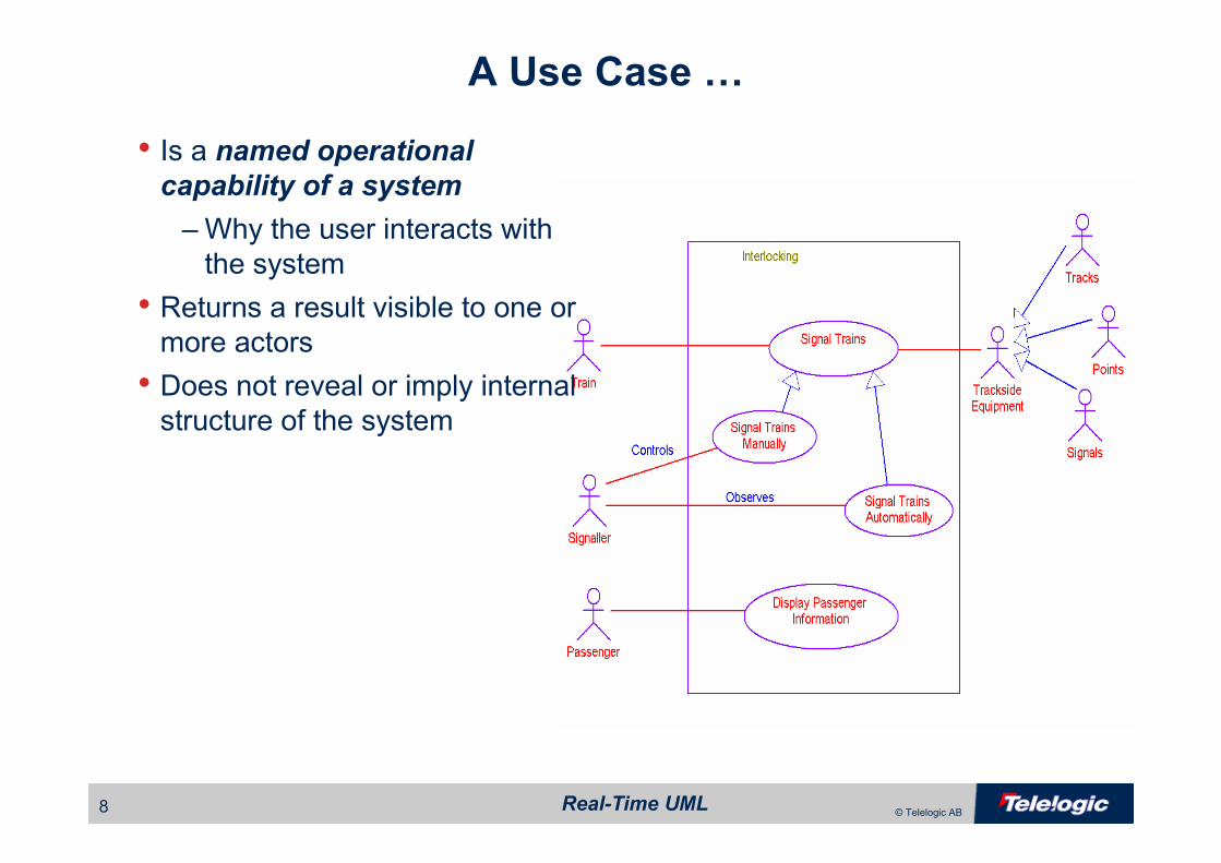
• Is a named operational capability of a system
–Why the user interacts with
the system
• Returns a result visible to one or more actors
• Does not reveal or imply internal structure of the system
Real-Time UML9 © Telelogic AB
A Use Case Is Used to
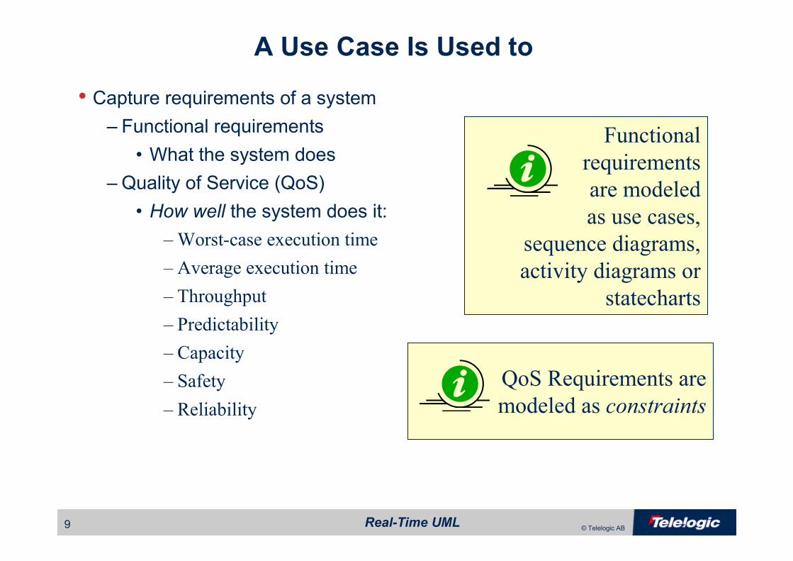
• Capture requirements of a system– Functional requirements
• What the system does
– Quality of Service (QoS)
• How well the system does it:
– Worst-case execution time
– Average execution time
– Throughput
– Predictability
– Capacity
– Safety
– Reliability
Functional
requirements
are modeled
as use cases,
sequence diagrams,
activity diagrams or
statecharts
QoS Requirements are
modeled as constraints
Real-Time UML10 © Telelogic AB
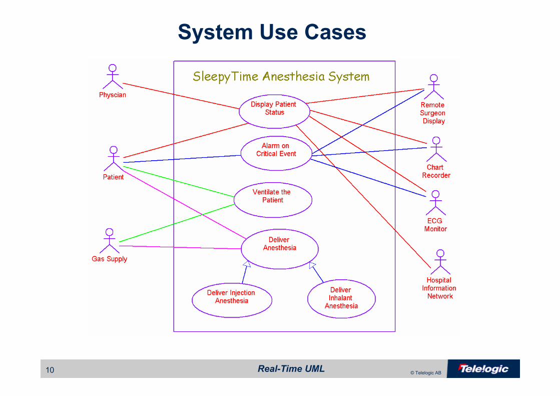
System Use Cases
Real-Time UML11 © Telelogic AB
Use Cases Are Not ..
• A functional decomposition model of the system internals – that’s HOW– They do not capture HOW in any way
– They do not capture anything the Actor does outside of the System
– How do I capture HOW?
• Use Object Model Diagrams to capture Static Structure
• Use Sequence Diagrams and State Diagrams (or Activity
Diagrams) to capture Dynamic Behavior
Real-Time UML12 © Telelogic AB
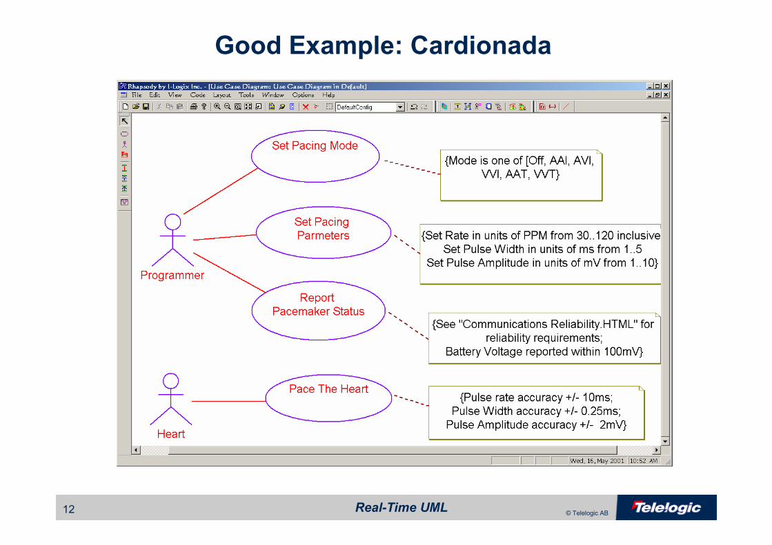
Good Example: Cardionada
Real-Time UML13 © Telelogic AB
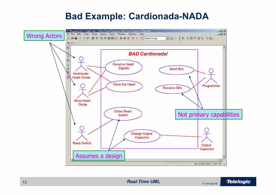
Bad Example: Cardionada-NADA
Wrong Actors
Assumes a design
Not primary capabilities
Real-Time UML14 © Telelogic AB
Things to avoid
• Single messages are not use cases!– Use cases represent a large number of different scenarios
– Each scenario has many (possibly hundreds) of messages
• Low-level interfaces are not use cases– Low-level interfaces are means to realize use cases
– LLI’s are subsumed within actual use cases
– A use case should map to a reason for the user to interact with
the system, not the means by which it occurs
Real-Time UML15 © Telelogic AB
Detailing Use Cases
• By operational example – Use scenarios captured via sequence diagrams
• Each scenario capture a specific path through the use case
– Partially constructive
– Infinite set, so you must select which are interestingly different
– Non-technical users can understand scenarios
• By specification– Use an informal (e.g. English) and/or formal (e.g. statechart) to
represent all possible paths
– Fully constructive
– Non-technical readers might not understand formal specs

Real-Time UML16 © Telelogic AB
Use Case Description
Real-Time UML17 © Telelogic AB
Detailing Use Cases: Scenarios
• A typical system has one dozen to a few dozen use case• Each use case typically has a few to several dozen scenarios of interest
• Scenarios capture a specific actor-system interaction– protocols of interaction
– permitted sequences of
message flow
– collaboration of structural elements
– show typical or exceptional paths through the use case

Real-Time UML18 © Telelogic AB
Example: Use Case Sequence Diagram
Real-Time UML19 © Telelogic AB
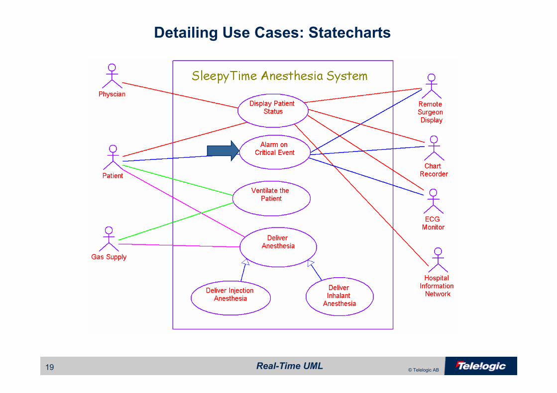
Detailing Use Cases: Statecharts

Real-Time UML20 © Telelogic AB
Detailing Use Cases: Statecharts
Alarm on
Critical Event
Real-Time UML21 © Telelogic AB
HowHow do we describe do we describe
structure using UML?structure using UML?
Real-Time UML22 © Telelogic AB
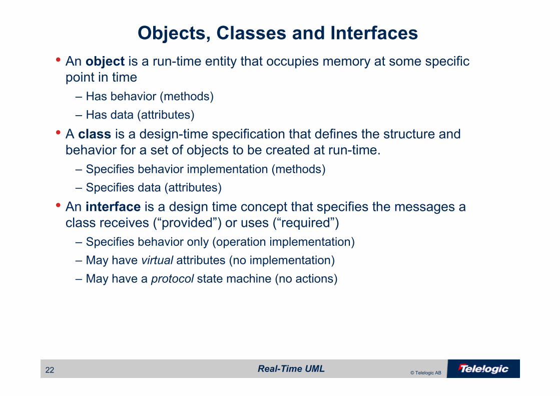
Objects, Classes and Interfaces
• An object is a run-time entity that occupies memory at some specific point in time
– Has behavior (methods)
– Has data (attributes)
• A class is a design-time specification that defines the structure and behavior for a set of objects to be created at run-time.
– Specifies behavior implementation (methods)
– Specifies data (attributes)
• An interface is a design time concept that specifies the messages a class receives (“provided”) or uses (“required”)
– Specifies behavior only (operation implementation)
– May have virtual attributes (no implementation)
– May have a protocol state machine (no actions)
Real-Time UML23 © Telelogic AB
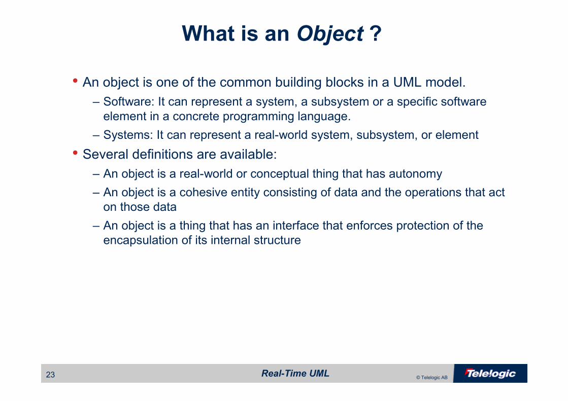
• An object is one of the common building blocks in a UML model. – Software: It can represent a system, a subsystem or a specific software
element in a concrete programming language.
– Systems: It can represent a real-world system, subsystem, or element
• Several definitions are available:– An object is a real-world or conceptual thing that has autonomy
– An object is a cohesive entity consisting of data and the operations that act
on those data
– An object is a thing that has an interface that enforces protection of the
encapsulation of its internal structure
What is an Object ?
Real-Time UML24 © Telelogic AB
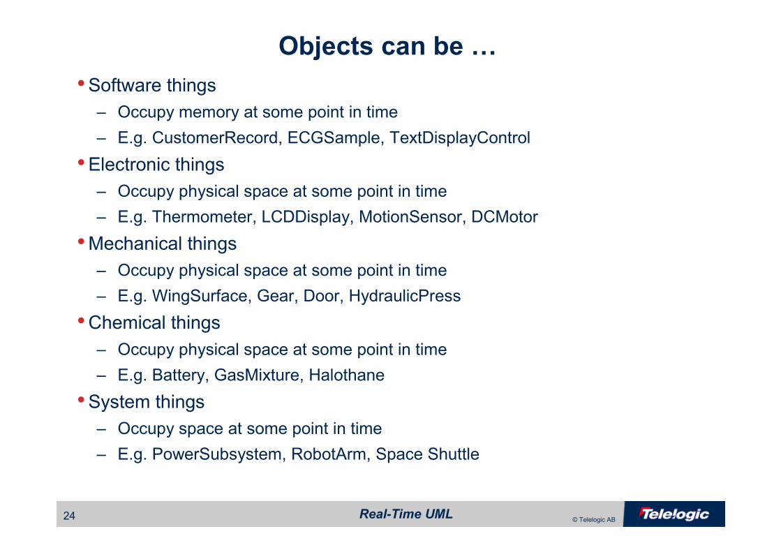
Objects can be …
•Software things– Occupy memory at some point in time
– E.g. CustomerRecord, ECGSample, TextDisplayControl
•Electronic things– Occupy physical space at some point in time
– E.g. Thermometer, LCDDisplay, MotionSensor, DCMotor
•Mechanical things– Occupy physical space at some point in time
– E.g. WingSurface, Gear, Door, HydraulicPress
•Chemical things– Occupy physical space at some point in time
– E.g. Battery, GasMixture, Halothane
•System things– Occupy space at some point in time
– E.g. PowerSubsystem, RobotArm, Space Shuttle

Real-Time UML25 © Telelogic AB
• A Class is the definition or specification of an object
• An object is an instance of a class• An object has the attributes and behaviours defined by its class• It is common to have many instances of a class at the same time
Human (class)
Sam(Object)
Phil (Object) Lauren (Object)
Classes
is a instance of
is an instance of
is an instance of
Real-Time UML26 © Telelogic AB
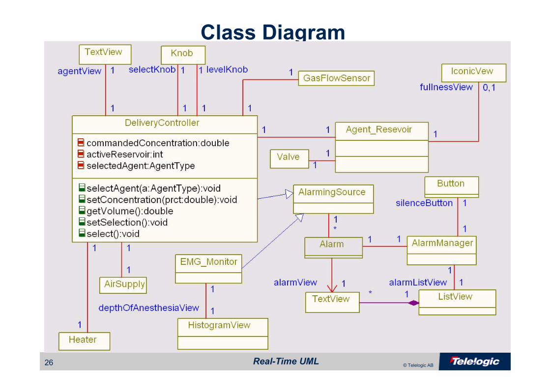
Class Diagram

Real-Time UML27 © Telelogic AB
Structural Diagrams
• Diagrams serve many purposes– System model-capture & specification
– View aspects of system design
– Provide basis for communication and review
• Diagrams bring 2 things to the design process– Represent different aspects of design, e.g.
• Functional
• Structural
• Behavioral
• Quality of Service
– Show aspects at different levels of abstraction
• System
• Subsystem
• Component
• “Primitive” class
Real-Time UML28 © Telelogic AB
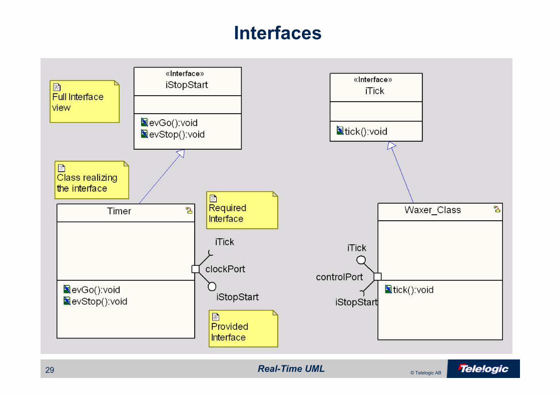
Interfaces
• UML interfaces specify operations or event receptions• UML Interfaces have no implementation
– No methods
– No attributes
• Classes realize an interface by – providing a method (implementation) of an operation or
– specifying an event reception on a state machine
• A class that realizes an interface is said to be compliant with that interface
– Classes may realize any number of interfaces
– Interfaces may be realized by any number of classes
Real-Time UML29 © Telelogic AB
Interfaces

Real-Time UML30 © Telelogic AB
• Relationships allow objects to communicate at run-time• Objects may use the facilities of other objects with an association• There are two specialized forms of association:
– Objects may contain other objects with an aggregation
– Objects may strongly aggregate others via composition
• Classes may derive attributes and behaviours from other classes with a generalization
• Classes may depend on others via a dependency
Relationships

Real-Time UML31 © Telelogic AB
• Associations allow instances of classes to communicate at run-time– Instances of associations are called links
– Links may come and go during execution
• Denotes one object using the facilities of another• Lifecycles of the objects are independent• Allows objects to provide services to many others
Associations
Real-Time UML32 © Telelogic AB
• Associations may have labels– This is the “name” of the association
• Associations may have role names– Identifies the role of the object in the association
• Associations may indicate multiplicity– Identifies the number of instances of the class that participate in the association
• N
• *
• 1..[n | *]
• Associations may indicate navigation with an open arrowhead
– Unadorned associations are assumed to be bi-directional
– Most associations are unidirectional
Associations
Real-Time UML33 © Telelogic AB
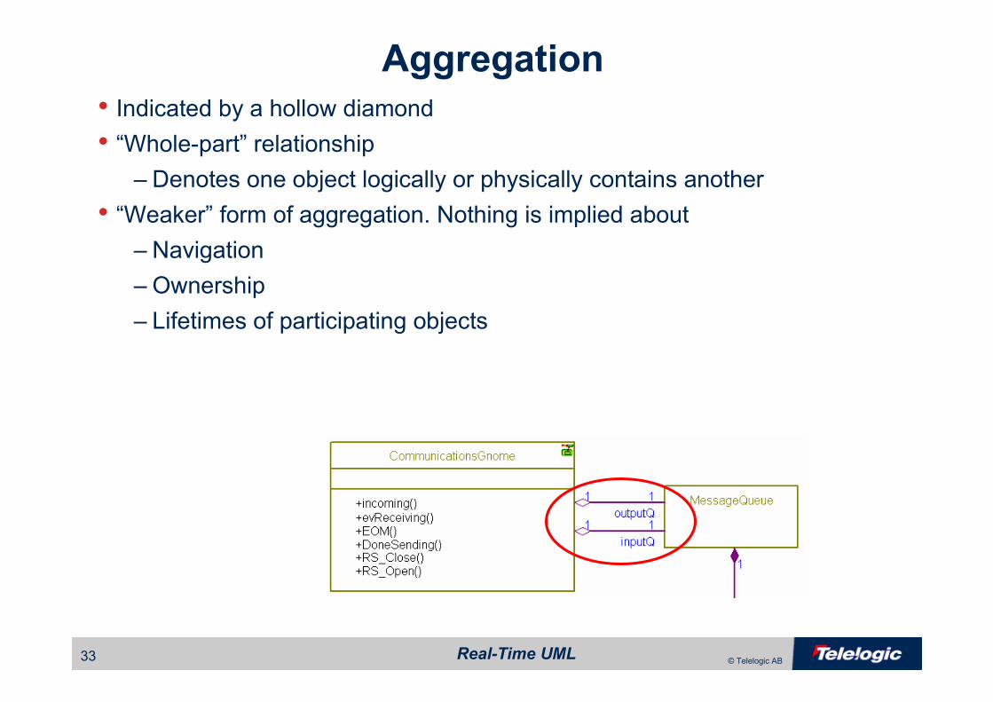
• Indicated by a hollow diamond • “Whole-part” relationship
– Denotes one object logically or physically contains another
• “Weaker” form of aggregation. Nothing is implied about
– Navigation
– Ownership
– Lifetimes of participating objects
Aggregation
Real-Time UML34 © Telelogic AB
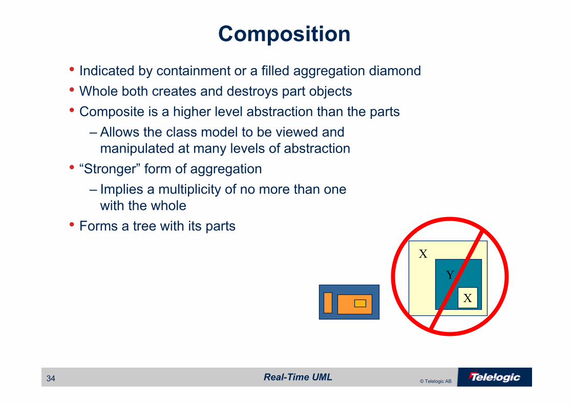
• Indicated by containment or a filled aggregation diamond• Whole both creates and destroys part objects
• Composite is a higher level abstraction than the parts– Allows the class model to be viewed and
manipulated at many levels of abstraction
• “Stronger” form of aggregation– Implies a multiplicity of no more than one
with the whole
• Forms a tree with its parts
Y
X
X
Composition

Real-Time UML35 © Telelogic AB
Composition Example
Keypad Display
System
FrontPanel
Button LED
Acquisition Filter Measurement
AcquisitionSubsystem
1 1
1 1
8 4
11 1
11
System
:AcquisitionSubsystem1
:FrontPanel1
AcquisitionSubsystem
:Acquisition1
:Filter1
:Measurement1
1
1
FrontPanel
:Keypad1
:Display1
Keypad
:Button8
:LED4
Two waysto show
composition
Real-Time UML36 © Telelogic AB
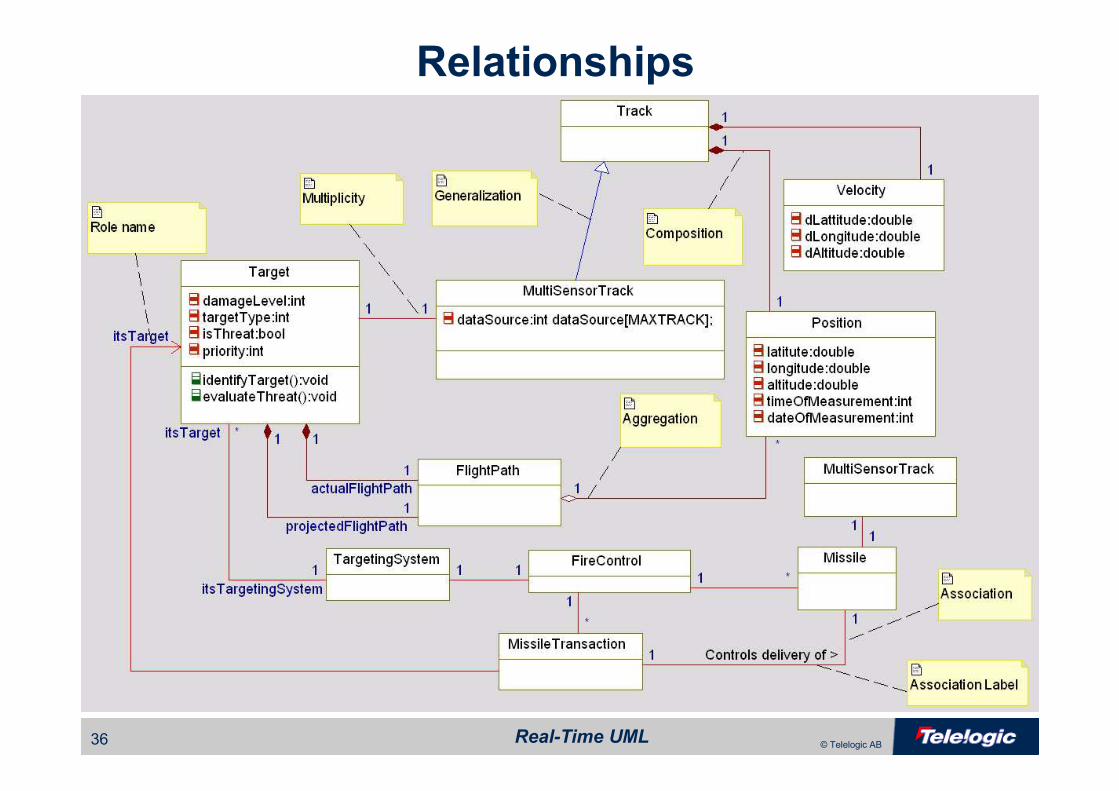
Relationships
Real-Time UML37 © Telelogic AB
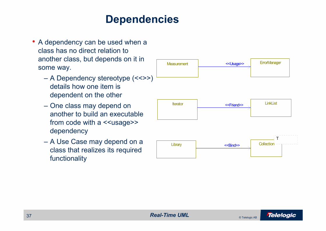
Dependencies
• A dependency can be used when a class has no direct relation to
another class, but depends on it in
some way.
– A Dependency stereotype (<<>>)
details how one item is
dependent on the other
– One class may depend on
another to build an executable
from code with a <<usage>>
dependency
– A Use Case may depend on a
class that realizes its required
functionality
Measurement ErrorManager
LinkList
T
CollectionLibrary
Iterator
<<Usage>>
<<Friend>>
<<Bind>>
Real-Time UML38 © Telelogic AB
Advanced Structural ConceptsAdvanced Structural Concepts

Real-Time UML39 © Telelogic AB
Advanced Structural Concepts
• Flows• Structure Classes• Ports

Real-Time UML40 © Telelogic AB
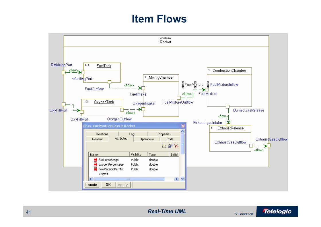
Information Flows
• Information flows are an abstract view of collaboration
– Information items represent data
• Similar to data flow diagrams– Non-constructive
– No sequence is shown
• Information Flows are details with data elements known as Flow
Items
– Flow Items can be primitive types, records containing other items, or
even classes
• Operations and event receptions on the target class will realizeinformation flow
– Information flow items will be parameters or return values of the
operations
Real-Time UML41 © Telelogic AB
Item Flows
Real-Time UML42 © Telelogic AB
Structured Classes
•A structured class is a class that is composed of parts
– The structured class is responsible for the creation and destruction of its
parts
– The structured class “owns” the parts via composition
•A part is an object role that executes in the context of the structured
class
– Parts are typed by classes
•Parts are connected via connections
– Connections are contextualized links
– The structured class links together the parts as necessary

Real-Time UML43 © Telelogic AB
Structured Classes
• PRIMARY USE: show systems at different levels of abstraction– Composite is at a higher level of abstraction than the part (e.g. system and subsystem)
– Composite achieves its behavioral goals primarily through delegation
• Additional use: Populate simple classes into «active» classes for concurrency
• Additional use: Use composites to aid in system boot and object construction
Real-Time UML44 © Telelogic AB
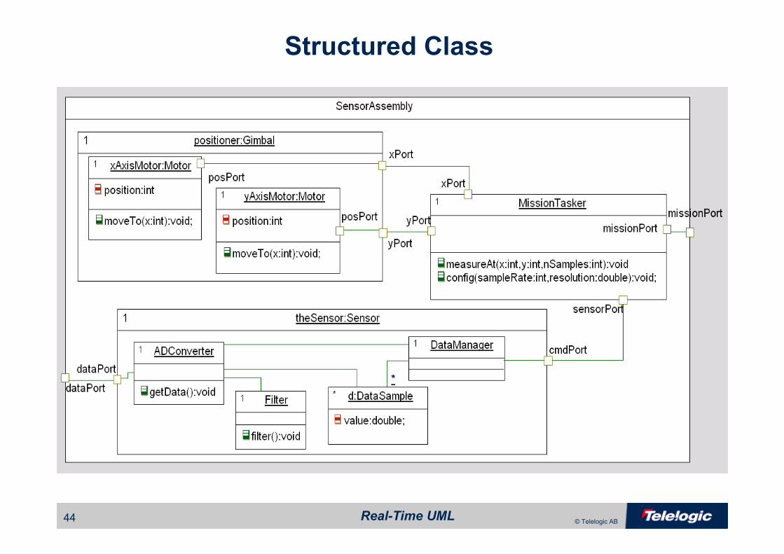
Structured Class
Real-Time UML45 © Telelogic AB
Parts and Ports
• Ports are “named connection points”
• Ports allow a part to provide an interface across the boundary of its enclosing structured class without revealing to the client of the service
the internal structure of the structured class
– Client “talks to” the port without internal knowledge
• Ports are “typed by” their interfaces– Provided interfaces
– Required Interfaces
Real-Time UML46 © Telelogic AB
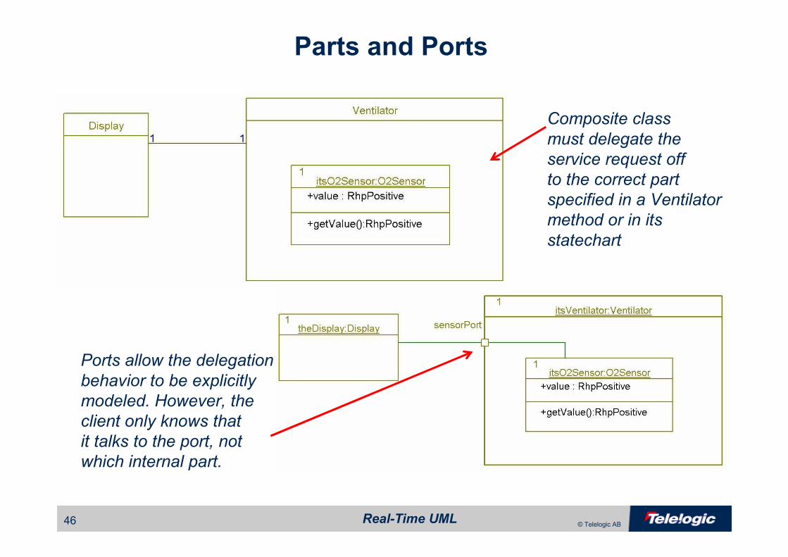
Parts and Ports
Composite class
must delegate the
service request off
to the correct part
specified in a Ventilator
method or in its
statechart
Ports allow the delegation
behavior to be explicitly
modeled. However, the
client only knows that
it talks to the port, not
which internal part.
Real-Time UML47 © Telelogic AB
Interfaces with Ports
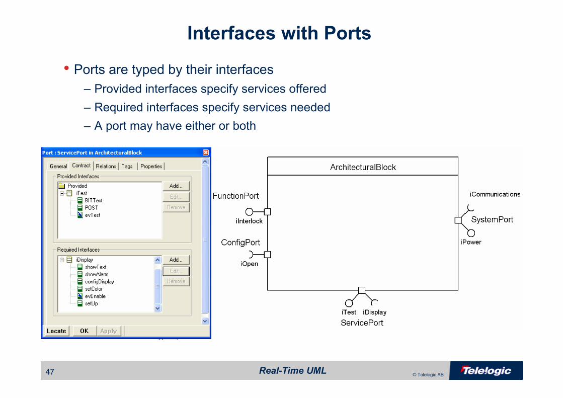
• Ports are typed by their interfaces– Provided interfaces specify services offered
– Required interfaces specify services needed
– A port may have either or both

Real-Time UML48 © Telelogic AB
Port Example
Real-Time UML49 © Telelogic AB
How do we How do we
describe behavior?describe behavior?
Real-Time UML50 © Telelogic AB
Sequence Diagrams
• Sequence diagrams show the behavior of a group of instances (e.g. objects) over time. Instances may be
– Objects (most common)
– Use case instance
– System
– Subsystem
– Actor
• Useful for– Capturing typical or exceptional interactions for requirements
– Understanding collaborative behavior
– Testing collaborative behavior
Real-Time UML51 © Telelogic AB
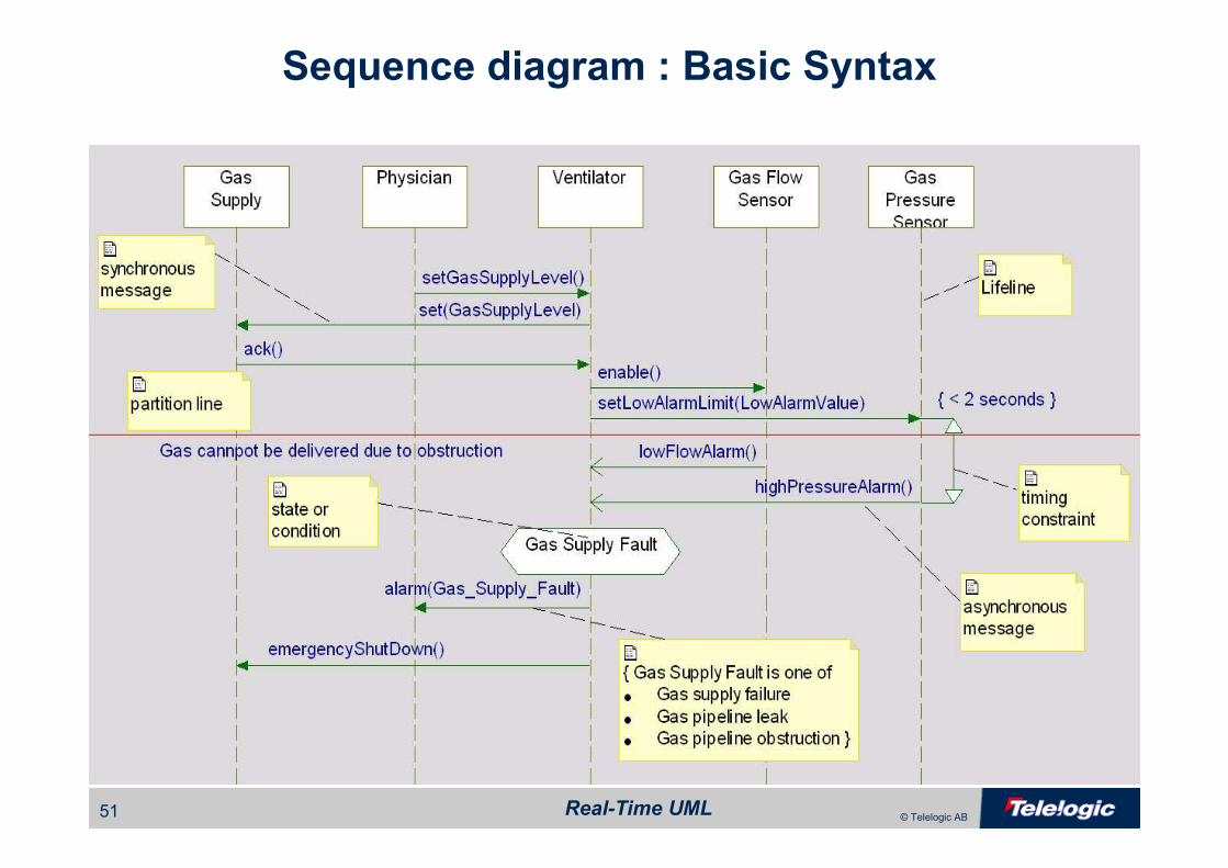
Sequence diagram : Basic Syntax
Real-Time UML52 © Telelogic AB
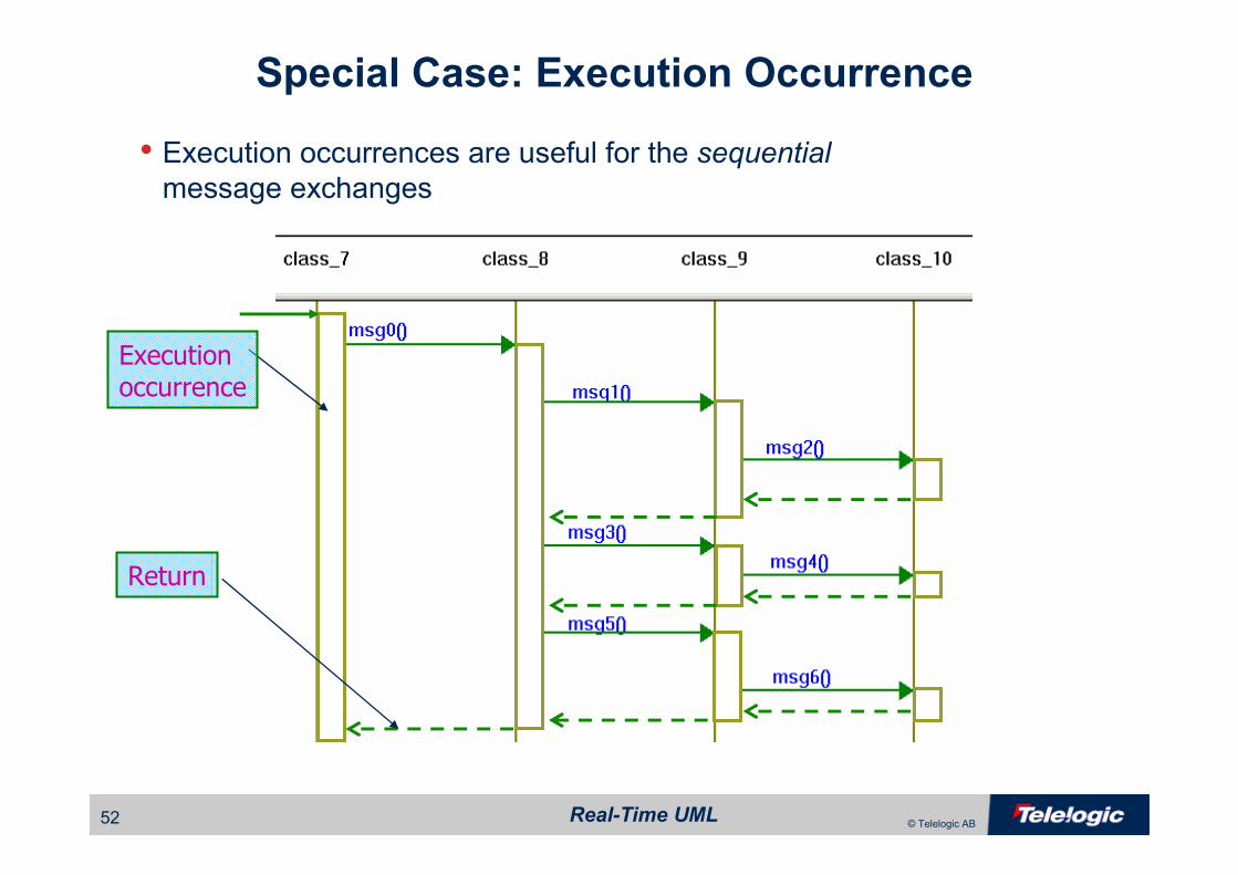
Special Case: Execution Occurrence
• Execution occurrences are useful for the sequential
message exchanges
Executionoccurrence
Return
Real-Time UML53 © Telelogic AB
Deriving Test Vectors from Scenarios
• A scenario is an example execution of a system• A test vector is an example execution of a system with a known expected result
• Scenario � Test Vector
– Capture preconditions
– Determine test procedure
• Identify causal messages and events
• Instrument test fixtures to insert causal messages
– Remove optional or “incidental” messages
– Define pass/fail criteria
• Identify effect messages / states
• Postconditions
• Required QoS
Real-Time UML54 © Telelogic AB
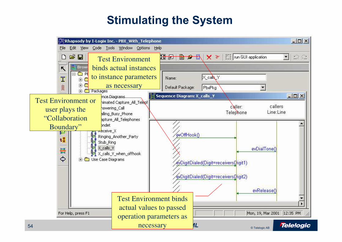
Stimulating the System
Test Environment or
user plays the
“Collaboration
Boundary”
Test Environment
binds actual instances
to instance parameters
as necessary
Test Environment binds
actual values to passed
operation parameters as
necessary

Real-Time UML55 © Telelogic AB
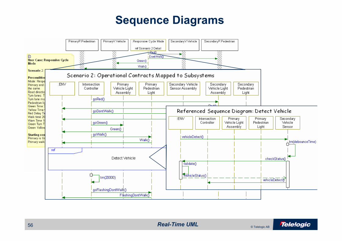
Decomposing Sequence Diagrams
•Sequence diagrams suffer from scalability problems when there are many
– Lifelines
– Messages
•UML 2 provides the ability to decompose sequence diagrams both vertically and horizontally
– Lifelines may be decomposed into interactions (separate sequence
diagrams
– Interaction fragments may be referenced on another diagram
Real-Time UML56 © Telelogic AB
Sequence Diagrams
Real-Time UML57 © Telelogic AB
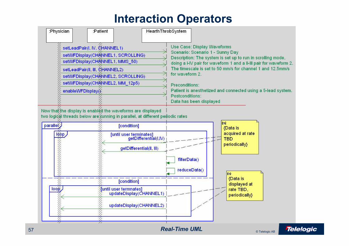
Interaction Operators

Real-Time UML58 © Telelogic AB
UML 2.0 Timing Diagrams
sd Pacing
Time
:Atrial Model
Idle
Refractory
Sensing
Pacing
To Inhibited
A Sense
tm(Sense_tm)
tm(Pulse_tm)
tm(Ref Time)
lifeline
state or value
tick mark values0 2010
timing ruler
{ 20 +/- 0.5ms }
event or stimulus
{ sense_tm +/- 0.5ms }
timing constraint
timing constraint

Real-Time UML59 © Telelogic AB
UML 2.0 Timing Diagrams
sd Communicating
Time
Sending::Low
Sending::High
Receving::Low
Receiving::High
Sending
Receiving
IdleCoil Driver
Transceiver
transmit(value)
Tristate
Monitor Initializing
Acquiring
Reporting
Idle
label1
send(value)
tm(bitTime)
{1 ms +/- 0.2ms}
{5 ms +/- 0.2ms}
evDone
lifeline separator
label
label1
send(value)
event or stimulus
Real-Time UML60 © Telelogic AB
State Behavior
• Useful when object – Exhibits discontinuous modes of behaviour
– Waits for and responds to incoming events
• Sensor example– In Start up
• It must be configured before it can be used
• It may be turned off
– When it’s ready
• It rejects requests for data (data not yet available)
• It can go acquire data upon request
– Once it has data
• It may be asked for the sensed value (data has been acquired)
• It may get data periodically

Real-Time UML61 © Telelogic AB
State Machine Execution

Real-Time UML62 © Telelogic AB
• Created by professor David Harel of I-Logix in late 1980s• Statecharts were inserted into the UML by Eran Gery and David Harel of I-Logix
• Supports – Nested states
– Actions
– Guards
– History
• Advanced features– And-states
– Broadcast transitions
– Orthogonal regions
Statecharts
Real-Time UML63 © Telelogic AB
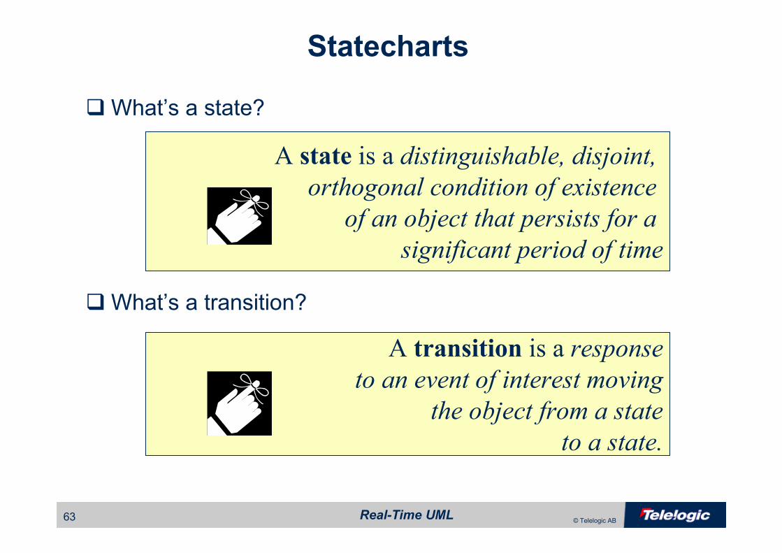
�What’s a state?
�What’s a transition?
A state is a distinguishable, disjoint,
orthogonal condition of existence
of an object that persists for a
significant period of time
A transition is a response
to an event of interest moving
the object from a state
to a state.
Statecharts
Real-Time UML64 © Telelogic AB
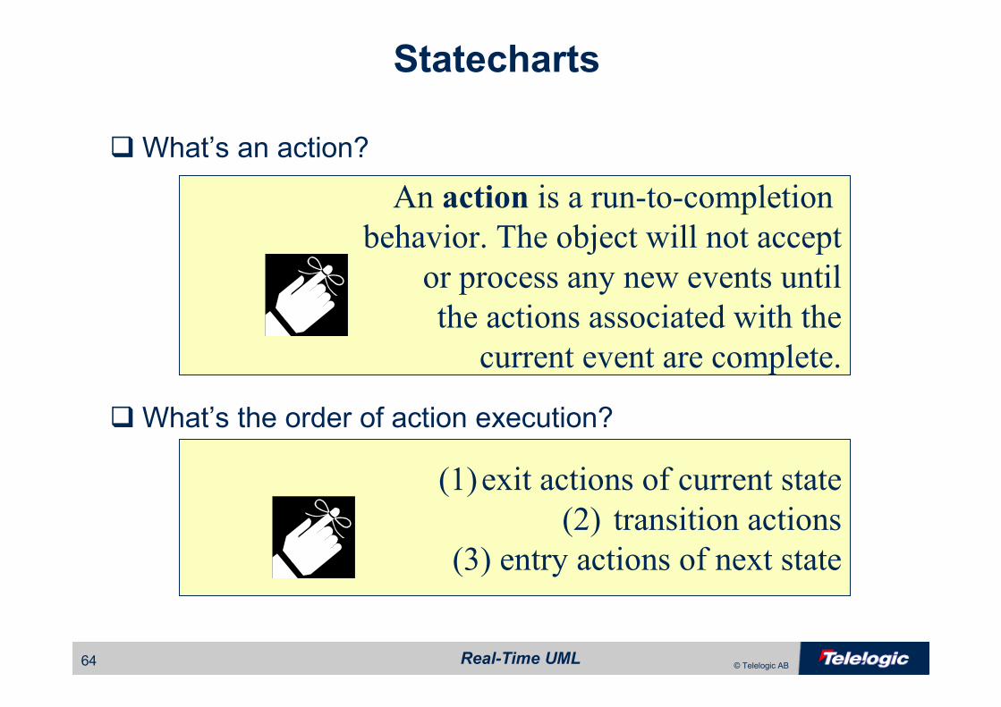
�What’s an action?
�What’s the order of action execution?
An action is a run-to-completion
behavior. The object will not accept
or process any new events until
the actions associated with the
current event are complete.
(1)exit actions of current state
(2) transition actions
(3) entry actions of next state
Statecharts
Real-Time UML65 © Telelogic AB
UML State Models
• Specifies the behaviour for reactive classes• Not all classes have state behaviour• Notation and semantics are Harel Statecharts
– Nested States
– Actions on
• Transitions
• State Entry
• State Exit
Actions are run-to-
completion behaviours

Real-Time UML66 © Telelogic AB
Basic Statechart Syntax
B
evX(int r)[r < 0] / f(r)A
entry / g(x), h(y)
exit / m(a), n(b)
ev3 / p(x,y), q(z)
Guard
Action List
State State name
Entry actions
Exit actions
Internal Transitions(“Reactions in State”)
Event parameters
Event name
Real-Time UML67 © Telelogic AB
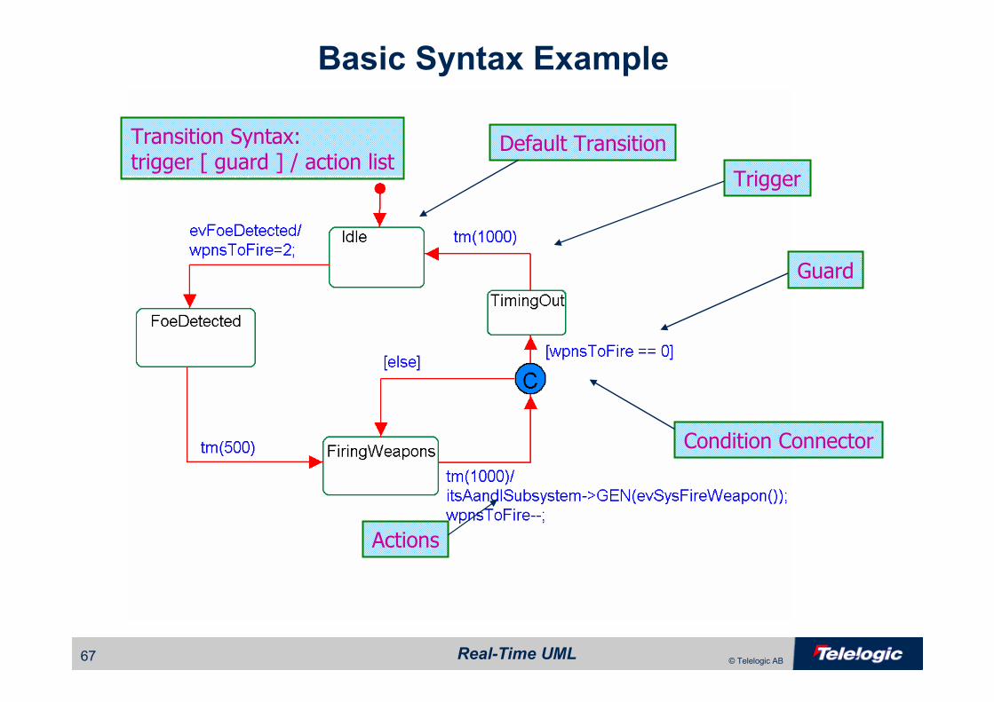
Basic Syntax Example
Condition Connector
Trigger
Guard
Actions
Transition Syntax:trigger [ guard ] / action list
Default Transition
Real-Time UML68 © Telelogic AB
Types of Events
• UML defines 4 kinds of events– Signal Event
• Asynchronous signal received e.g. evStart
– Call Event
• operation call received e.g. opCall(a,b,c)
– Change Event
• change in value occurred
– Time Event
• Absolute time arrived
• Relative time elapsed e.g. tm(PulseWidthTime)
Real-Time UML69 © Telelogic AB
Handling Transitions
• If an object is in a state S that responds to a named event evX, then it
will act upon that event
• It will transition to the specified state, if the event triggers a named
transition and the guard (if any) on that transition evaluates to TRUE. It
will execute any actions associated with that transition
• Handle the event without changing state if the event triggers a named
reaction and execute all the list of actions associated with that reaction
Real-Time UML70 © Telelogic AB
• A guard is some condition that must be met for the transition to be taken• Guards are evaluated prior to the execution of any action.
• Guards can be:– Variable range specification ex: [cost<50]
– Concurrent state machine is in some state [IS_IN(fault)]
– Some other constraint (preconditional invariant) must be met
Transitions: Guards
Real-Time UML71 © Telelogic AB
Actions
• Actions are run to completion– Normally actions take a short period of time to perform
– They may be interrupted by another thread execution, but that object
will complete its action list before doing anything else
• Actions are implemented via – An object’s operations
– Externally available functions
• They may occur when– A transition is taken
– A reaction occurs
– A state is entered
– A state is exited

Real-Time UML72 © Telelogic AB
Null-triggered Transitions
Null-triggered transitions trigger immediately upon completion of any actions-on-entry. If the guard ‘isDataReady()’ evaluates to FALSE, then the ONLY WAY it will ever be evaluated again is if event evPoll occurs, retriggering the null-triggered transition.

Real-Time UML73 © Telelogic AB
Timeouts
• When an object enters a state, any Timeout from that state are
started
• When a Timeout Expires, the State machine receives the expiration
as an event
• When an object leaves a state, any timeout that was started on entry
to that state are cancelled
• Only one timeout can be used per state, nested states can be used if several timeouts are needed

Real-Time UML74 © Telelogic AB
Timeouts
• Timeout Example:

Real-Time UML75 © Telelogic AB
Statechart Syntax – OR States
OR States
OR States
OR States
Real-Time UML76 © Telelogic AB
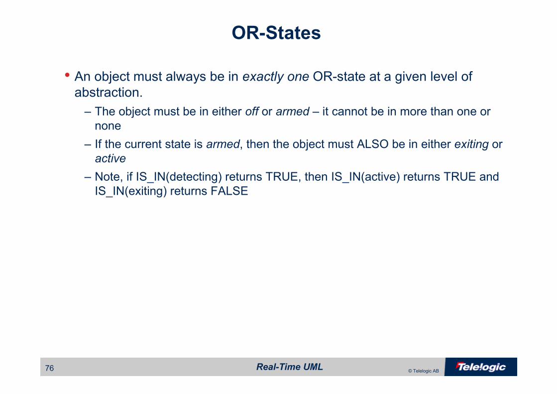
OR-States
• An object must always be in exactly one OR-state at a given level of
abstraction.
– The object must be in either off or armed – it cannot be in more than one or
none
– If the current state is armed, then the object must ALSO be in either exiting or
active
– Note, if IS_IN(detecting) returns TRUE, then IS_IN(active) returns TRUE and
IS_IN(exiting) returns FALSE

Real-Time UML77 © Telelogic AB
Statechart Syntax – Nested States
Nested States Composite State
Real-Time UML78 © Telelogic AB
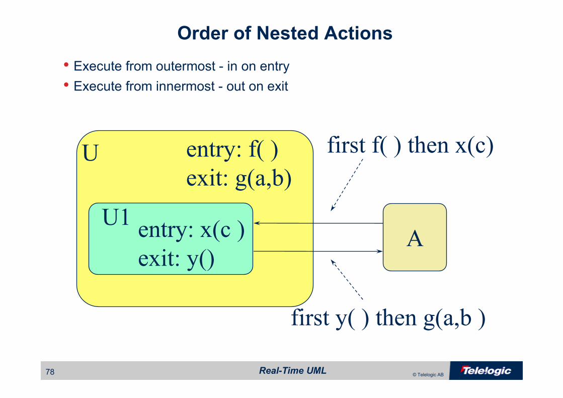
Order of Nested Actions
• Execute from outermost - in on entry• Execute from innermost - out on exit
U entry: f( )
exit: g(a,b)
U1entry: x(c )
exit: y()A
first f( ) then x(c)
first y( ) then g(a,b )

Real-Time UML79 © Telelogic AB
active
codeEntryarmingDisarmingReprogramming
active
currentCode
different correct
notEntered
enteringCode
reprogramming
waitOldCode
waitNewCode
idle
C
C
C
tm(3000) tm(3000)
tm(5000)
evKeyOff
evKey/
newCode = params->n;
count=1;
[isCodeCorrect()]
[isCodeEntered()]
[else]
evKey/
newCode = (10 * newCode ) + params->n;
count++;
[IS_IN(correct)]
[else]
evKeyOn
evKeyOff[IS_IN(correct)]/
itsAlarmController->GEN(evDisarm);
evKeyOff
evKeyOn[IS_IN(different)]/
changeCode();
evKeyOn[IS_IN(correct)]/
itsAlarmController->GEN(evTemporise);
[IS_IN(notEntered)]
tm(10000)
Statechart Syntax – AND States
Orthogonal Component Separator
AND States
AND state name
Real-Time UML80 © Telelogic AB
AND-States
• When a state has multiple AND-states, the object must be in exactly one
substate of each active AND-State at the same time
• AND-states are logically concurrent– All active AND-states receive their own copy of any event the object receives
and independently acts on it or discards it
– Cannot tell in principle which and-state will execute the same event first
– Not necessarily concurrent in the thread or task sense
– NOTE: UML uses active objects as the primary means of modeling
concurrency
– AND-states may be implemented as concurrent threads, but that is not the
only correct implementation strategy

Real-Time UML81 © Telelogic AB
AND-State Communication
• AND-states may communicate via– Broadcast events
• All active AND-states receive their own copy of each received event and are
free to act on it or discard it
– Propagated events
• A transition in one AND-state can send an event that affects another
– Guards
• [IS_IN( state )] uses the substate of an AND-state in a guard
– Attributes
• Since the AND-states are of the same object, they “see” all the attributes of
the object
Real-Time UML82 © Telelogic AB
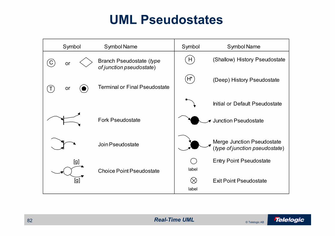
UML Pseudostates
T
C
H*
or
Symbol Symbol Name
orHBranch Pseudostate (type
of junction pseudostate)
Terminal or Final Pseudostate
Initial or Default Pseudostate
Fork Pseudostate
Join Pseudostate
Junction Pseudostate
(Shallow) History Pseudostate
(Deep) History Pseudostate
Choice Point Pseudostate
Merge Junction Pseudostate
(type of junction pseudostate)
[g]
[g]
Symbol Symbol Name
Entry Point Pseudostate
label
label
Exit Point Pseudostate
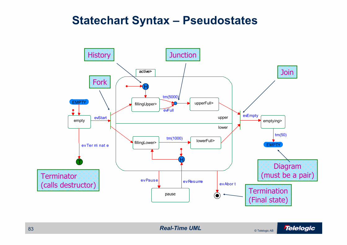
Real-Time UML83 © Telelogic AB
emptying>empty
active>
lower
upper
active>
lowerFull>fillingLower>
fillingUpper> upperFull>
pause
H
H
EMPTY
EMPTY
T
tm(1000)
tm(5000)
evFull
evResumeevPause
evStartevEmpty
tm(50)
evAbor t
evTer mi nat e
Statechart Syntax – Pseudostates
Fork
Junction
Join
Diagram(must be a pair)
Termination(Final state)
Terminator(calls destructor)
History
Real-Time UML84 © Telelogic AB
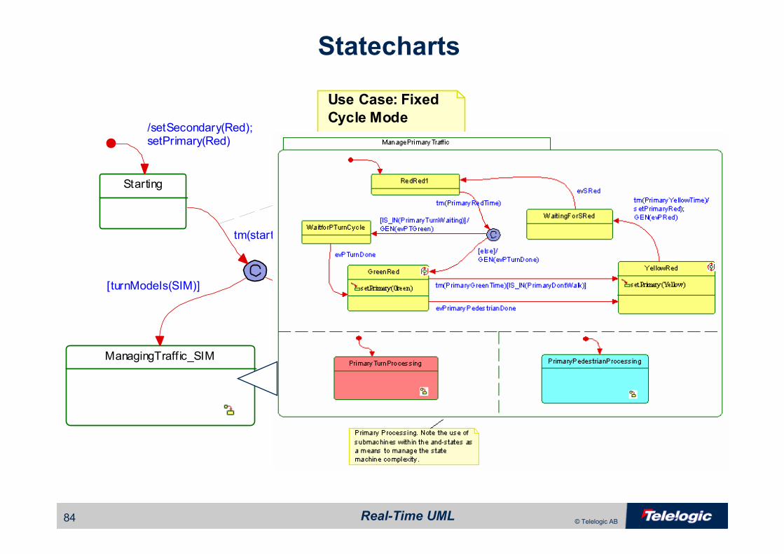
Statecharts
Starting
/setSecondary(Red);setPrimary(Red)
The startup time ensures that all traffic is
stopped before a mode change, for traffic
safety
Use Case: Fixed
Cycle Mode
ManagingTraffic_SIM ManagingTraffic_SEQ
tm(startupTime)
[turnModeIs(SIM)][turnModeIs(SEQ)]
Real-Time UML85 © Telelogic AB
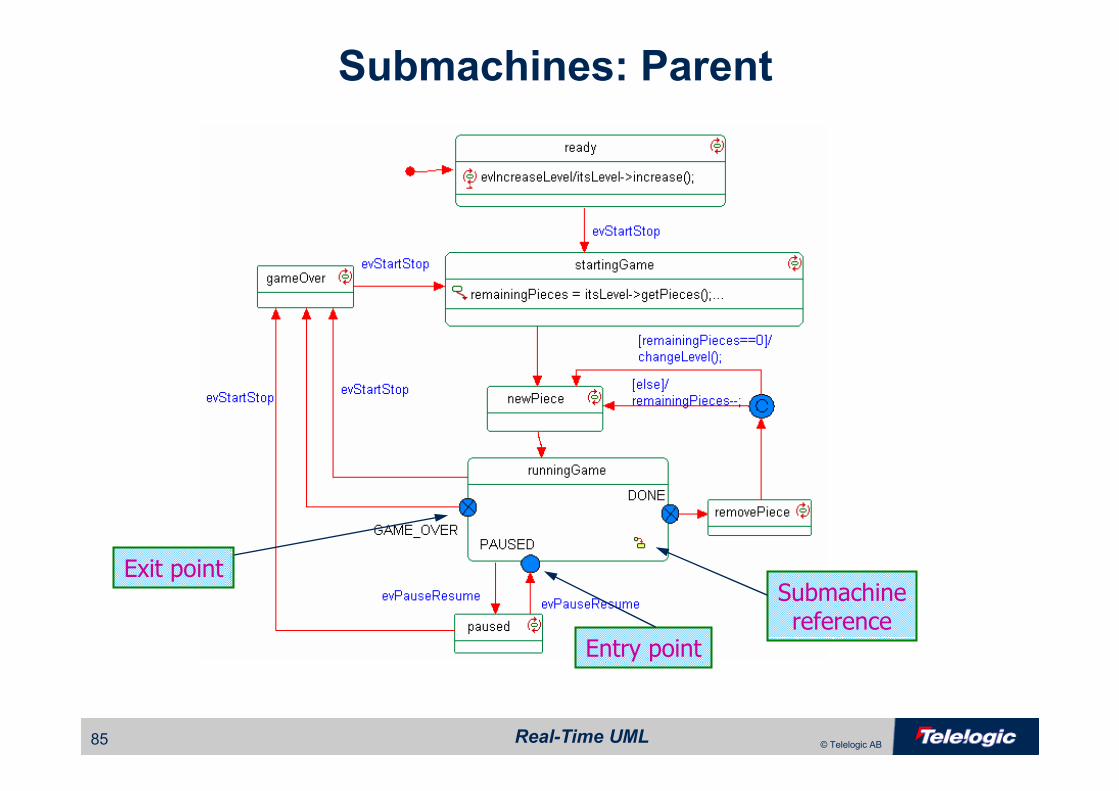
Submachines: Parent
Entry point
Submachinereference
Exit point

Real-Time UML86 © Telelogic AB
Submachines: Child
Submachine
Conditional Pseudostate

Real-Time UML87 © Telelogic AB
Poorly Formed Statecharts
e2
e3
Must be same event
Overlappingguards
No DefaultState
Race condition
Use beforeinitialization
Conflictingtransitions
Real-Time UML88 © Telelogic AB
Inherited State Behaviour
• Two approaches to inheritance for generalization of reactive classes
– Reuse (i.e. inherit) statecharts of parent
– Use custom statecharts for each subclass
• Reuse of statecharts allows
– Specialization of existing behaviours
– Addition of new states and transitions
– Makes automatic code generation of reactive classes efficient in
the presence of class generalization

Real-Time UML89 © Telelogic AB
Example: Generalization

Real-Time UML90 © Telelogic AB
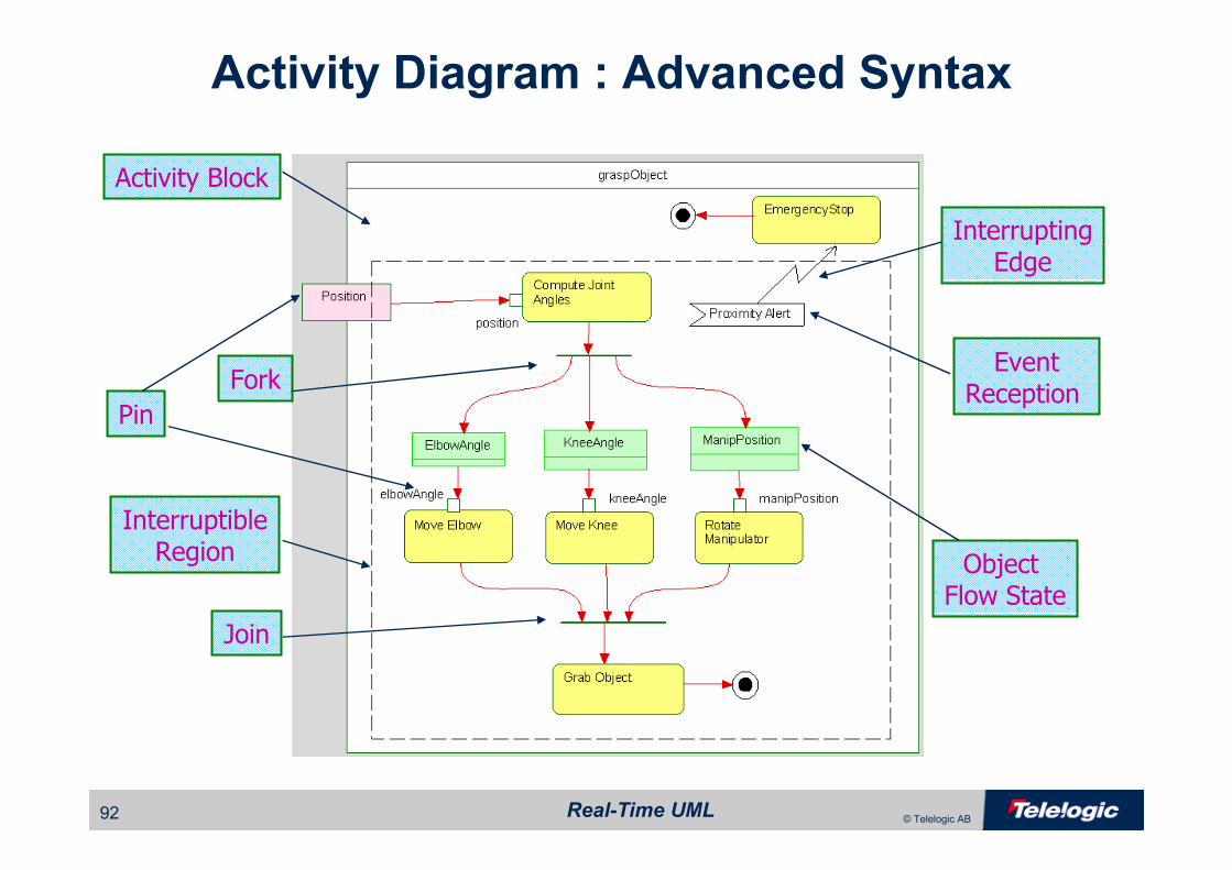
Activity Diagrams
• Change in 2.0 to be based on token flow semantics
• Used when the primary means of transitioning from one state to another is upon completion of the previous activity not reception of an event
– An activity diagram can be assigned to either a class, use case or an
operation.
– Useful for describing algorithms
• Each activity has a set of pins
– Input pins bind input parameters to “local variables”
– Output pins bind output parameters to “output variables”
– An activity begins when input data appears on all input pins
– When an activity completes, there is data on all the output pins
– Activities are no longer triggered by events

Real-Time UML91 © Telelogic AB
Activity Diagram : Basic Syntax
Default Transition
Action state
Transition
Guard
Conditionalpseudostate
Termination Connector
Real-Time UML92 © Telelogic AB
Activity Diagram : Advanced Syntax
Pin
Fork
InterruptingEdge
EventReception
Object Flow State
Activity Block
Join
InterruptibleRegion
Real-Time UML93 © Telelogic AB
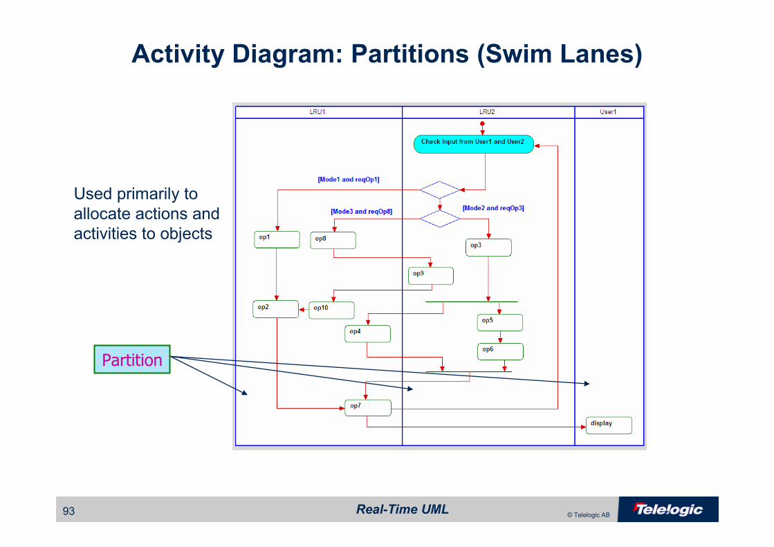
Activity Diagram: Partitions (Swim Lanes)
Partition
Used primarily to
allocate actions and
activities to objects
Real-Time UML94 © Telelogic AB
ArchitectureArchitecture

Real-Time UML95 © Telelogic AB
Physical Architectural Views
Subsystem and
Component View
Concurrency and
Resource View
Distribution V
iew
Safety and
Reliability ViewD
eployment
View
Real-Time UML96 © Telelogic AB
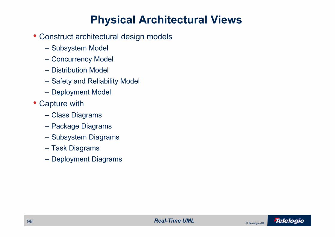
Physical Architectural Views
• Construct architectural design models– Subsystem Model
– Concurrency Model
– Distribution Model
– Safety and Reliability Model
– Deployment Model
• Capture with– Class Diagrams
– Package Diagrams
– Subsystem Diagrams
– Task Diagrams
– Deployment Diagrams

Real-Time UML97 © Telelogic AB
Subsystem Architecture
Real-Time UML98 © Telelogic AB
Subsystem and Component View
• A component– is the basic reusable element of software
– organizes objects together into cohesive run-time units that are replaced
together.
– provides language-independent opaque interfaces
– a metasubtype of (structured) Class
• A subsystem– is a large object that provides opaque interfaces to its clients and
achieves its functionality through delegation to objects that it owns
internally
– contains components and objects on the basis of common run-time
functional purpose
– a metasubtype of Component

Real-Time UML99 © Telelogic AB
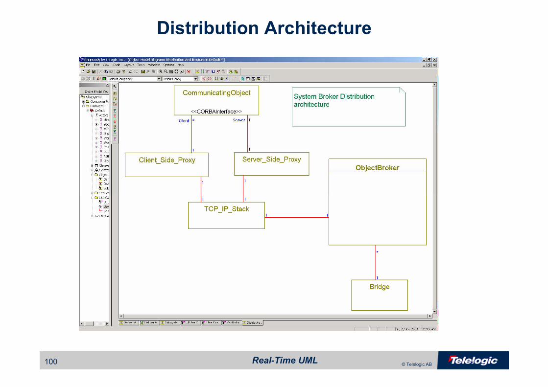
Distribution Architecture
• Distribution model refers to– Policies for distribution objects among multiple processors and
communication links, e.g.
• Asymmetric distribution (dedicated links to objects with a priori known location)
• Publish-Subscribe
• CORBA and Broker symmetric distribution
– Policies for managing communication links
• Communication protocols
• Communication quality of service management
Real-Time UML100 © Telelogic AB
Distribution Architecture

Real-Time UML101 © Telelogic AB
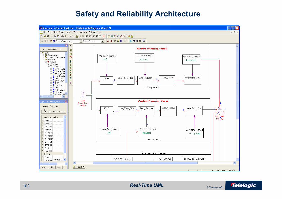
Safety and Reliability Model
• Safety and reliability model refers to the structures and policies in place to ensure
– Safety
• Freedom from accidents or losses
– Reliability
• High MTBF
• Fault tolerance
• Safety and fault tolerance always require some level of redundancy
Safety and reliability of object models is described more
completely in Doing Hard Time: Developing Real-Time
Systems with UML, Objects, Frameworks and Patterns
Real-Time UML102 © Telelogic AB
Safety and Reliability Architecture
Real-Time UML103 © Telelogic AB
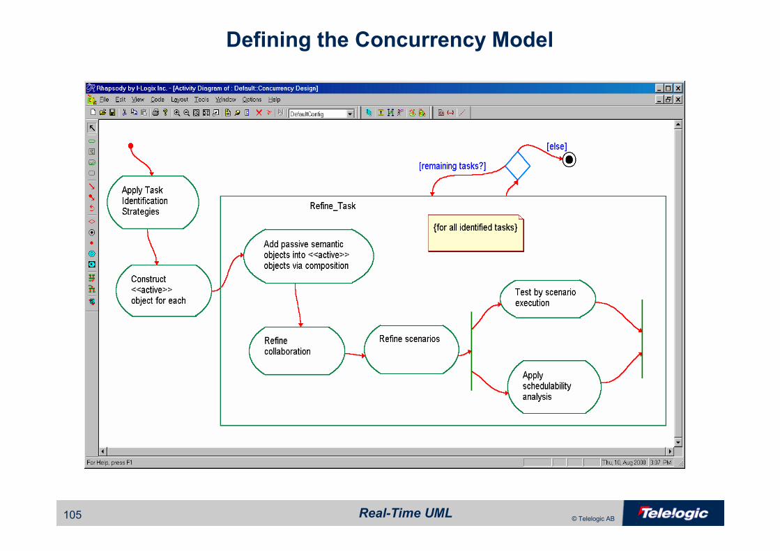
Concurrency Architecture
• Refers to– Identification of task threads and their properties
– Mapping of passive classes to task threads
– Identification of synchronization policies
– Task scheduling policies
• Unit of concurrency in UML is the «active» object– «active» objects are added in architectural design to organize passive
objects into threads
– «active» objects contain passive semantic objects via composition and
delegate asynchronous messages to them

Real-Time UML104 © Telelogic AB
Task Identification
Events with the same period, or aperiodic eventsEvent properties
For example, waveform queue or trend databaseTarget object
For example, BIT, redundant thread processing, watchdog tasksSafety Level
For example, a bus interfaceInterface device
For example, all numeric heart dataRelated information
group all events from a single source together for a threadEvent source
for simple systems, you may define a thread for each event typeSingle event groups
DescriptionTask Identification Strategy
Best forschedulabilty
Real-Time UML105 © Telelogic AB
Defining the Concurrency Model
Real-Time UML106 © Telelogic AB
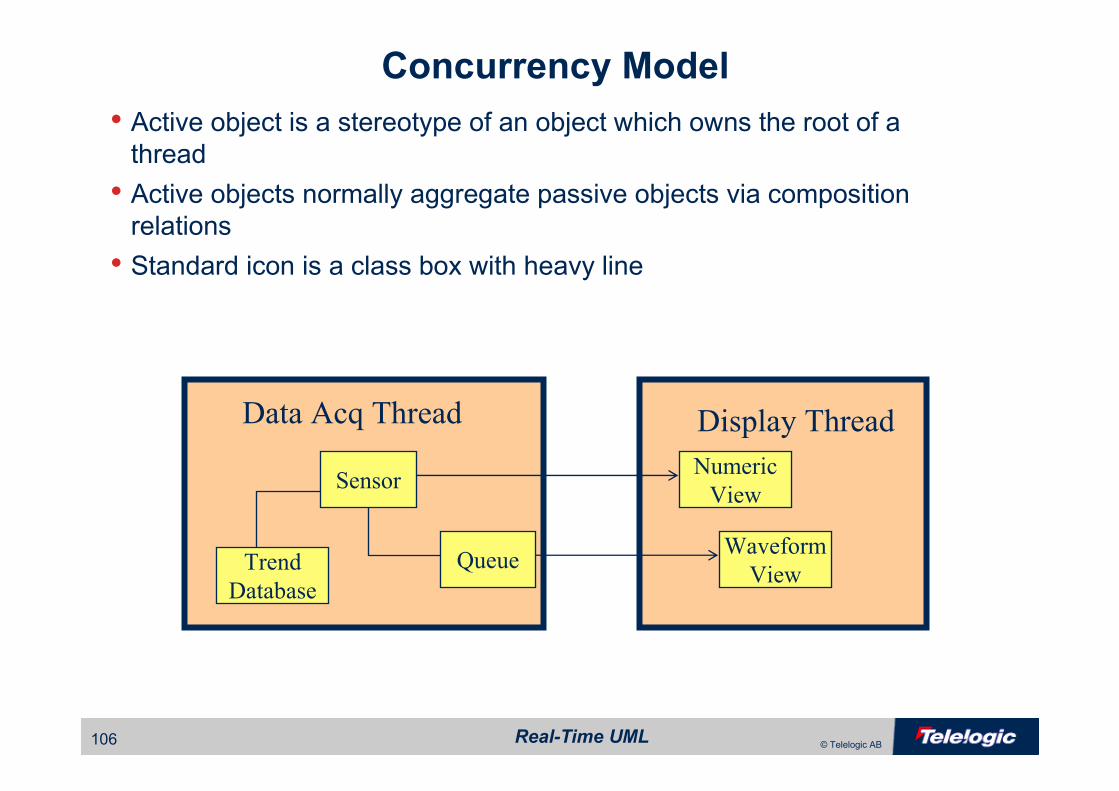
Data Acq Thread Display Thread
Concurrency Model
• Active object is a stereotype of an object which owns the root of a thread
• Active objects normally aggregate passive objects via composition relations
• Standard icon is a class box with heavy line
Queue
Sensor
Waveform
ViewTrend
Database
Numeric
View
Real-Time UML107 © Telelogic AB
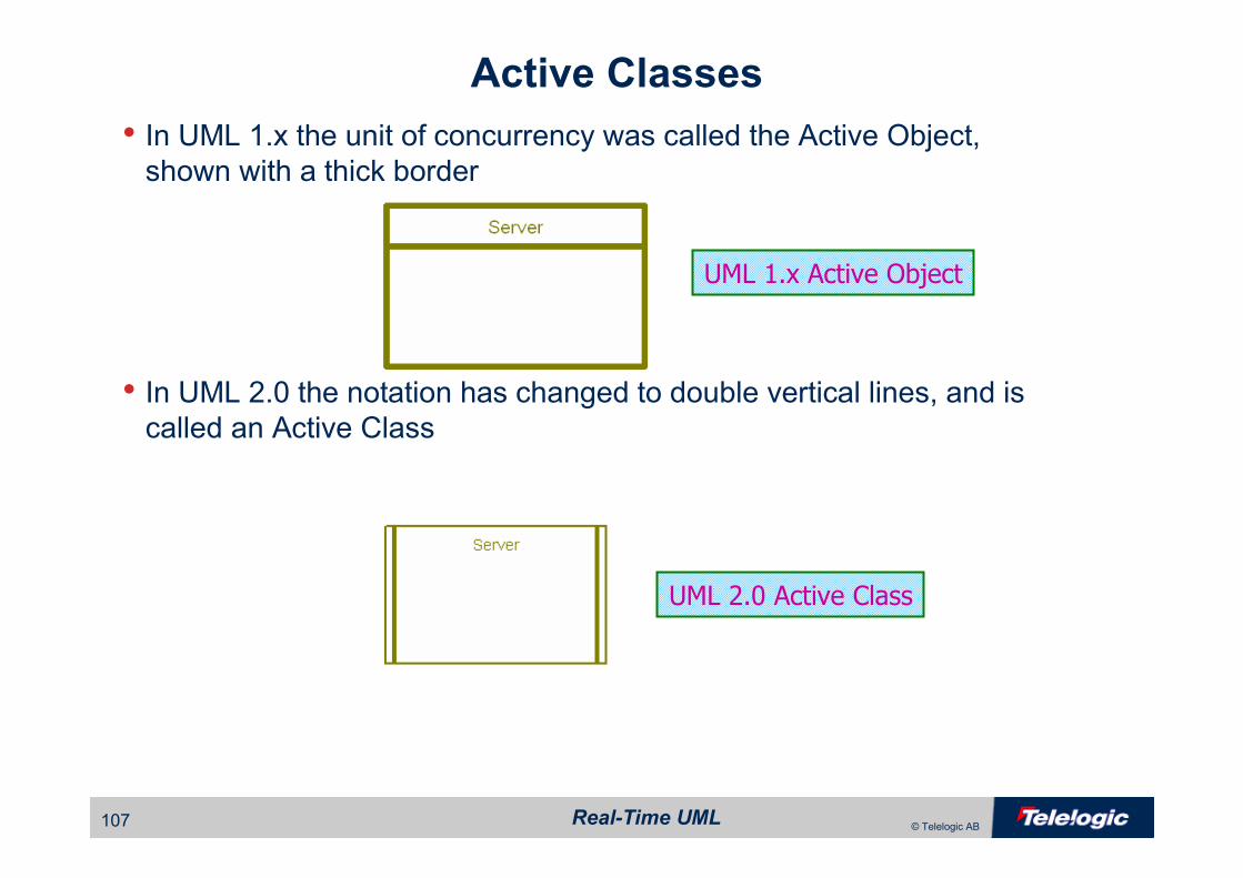
Active Classes
• In UML 1.x the unit of concurrency was called the Active Object,shown with a thick border
• In UML 2.0 the notation has changed to double vertical lines, and is called an Active Class
UML 1.x Active Object
UML 2.0 Active Class
Real-Time UML108 © Telelogic AB
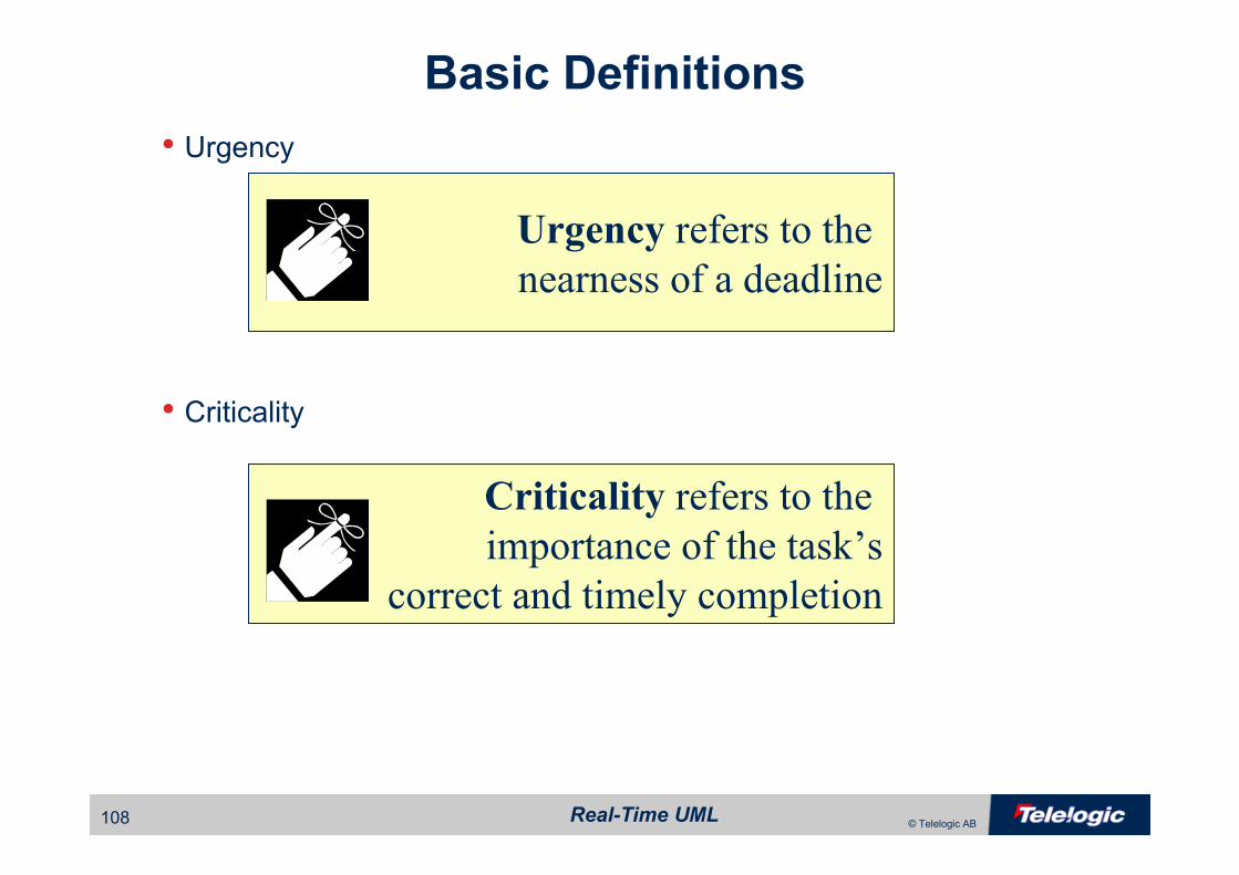
Basic Definitions
• Urgency
• Criticality
Urgency refers to the
nearness of a deadline
Criticality refers to the
importance of the task’s
correct and timely completion
Real-Time UML109 © Telelogic AB
Basic Definitions
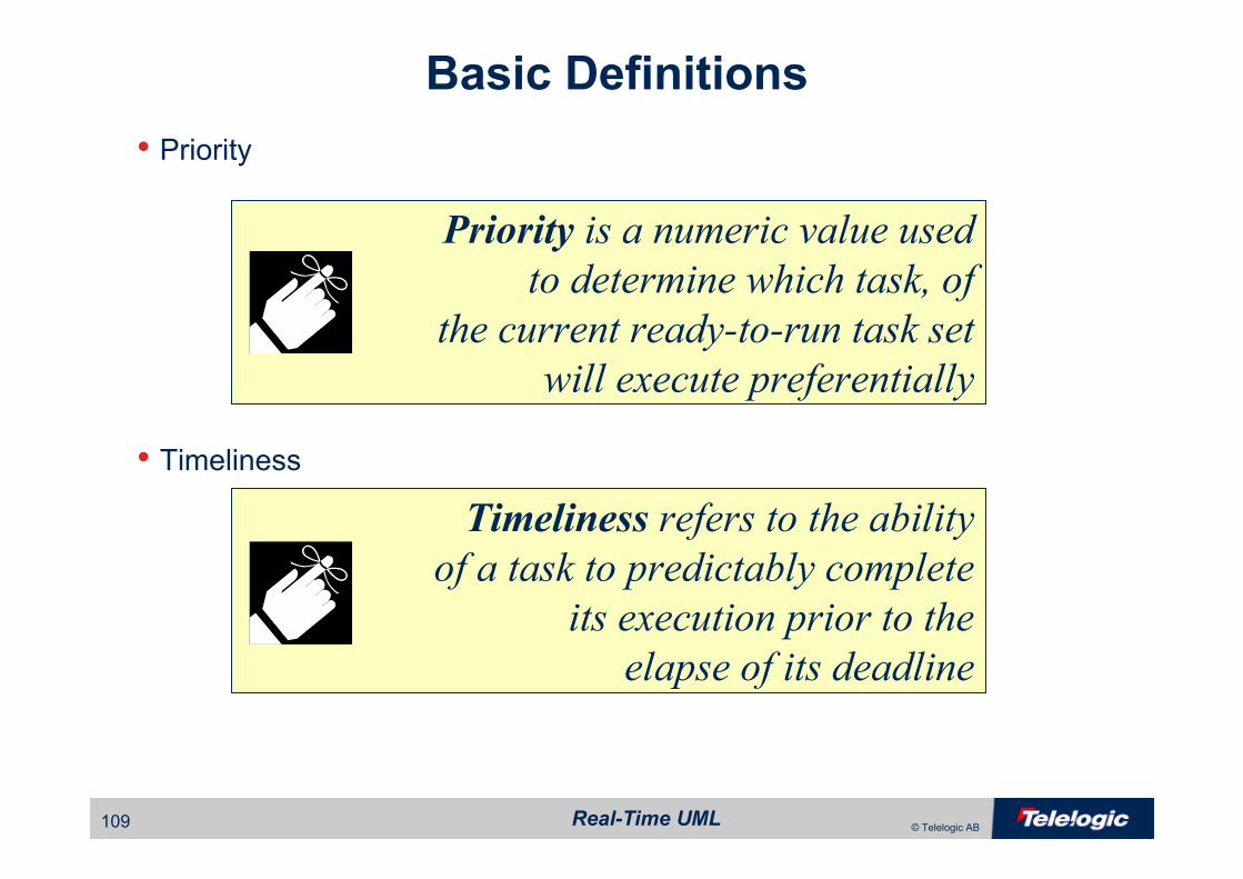
• Priority
• Timeliness
Priority is a numeric value used
to determine which task, of
the current ready-to-run task set
will execute preferentially
Timeliness refers to the ability
of a task to predictably complete
its execution prior to the
elapse of its deadline

Real-Time UML110 © Telelogic AB
Basic Definitions
• Deadline
• Schedulability
A deadline is a point in time
at which the completion of an
action becomes incorrect or irrelevant
A task set is schedulable if it can
be guaranteed that in all cases,
all deadlines will be met
Real-Time UML111 © Telelogic AB
Basic Definitions
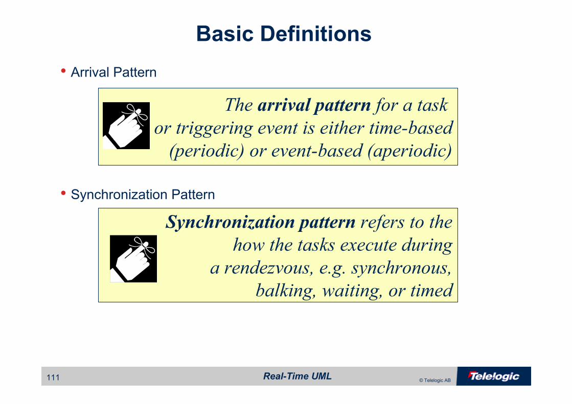
• Arrival Pattern
• Synchronization Pattern
The arrival pattern for a task
or triggering event is either time-based
(periodic) or event-based (aperiodic)
Synchronization pattern refers to the
how the tasks execute during
a rendezvous, e.g. synchronous,
balking, waiting, or timed
Real-Time UML112 © Telelogic AB
Basic Definitions
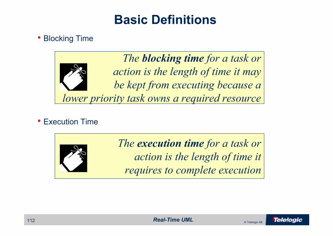
• Blocking Time
• Execution Time
The blocking time for a task or
action is the length of time it may
be kept from executing because a
lower priority task owns a required resource
The execution time for a task or
action is the length of time it
requires to complete execution

Real-Time UML113 © Telelogic AB
Task Diagram
• A task diagram is a class diagram that shows only model elementsrelated to the concurrency model
– Active objects
– Semaphore objects
– Message and data queues
– Constraints and tagged values
• May use opaque or transparent interfaces

Real-Time UML114 © Telelogic AB
Task Diagram
Tag Values
Active Classsymbol
Interrupt Routinescan (and should)also be shown

Real-Time UML115 © Telelogic AB
Task Performance Budgets
• The context defines the end-to-end performance requirements• This determines the overall task budget
– Computation of total budget may not just be simply adding up the times
due to concurrency
• Individual operations and actions within tasks must be assigned portions of the overall budget
– Action budgets should be checked during unit test
– Action budgets should take into account potential blocking
Real-Time UML116 © Telelogic AB
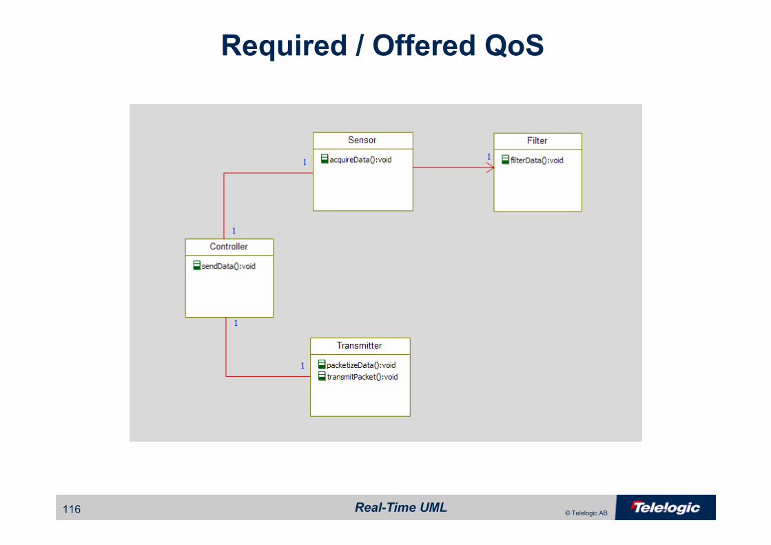
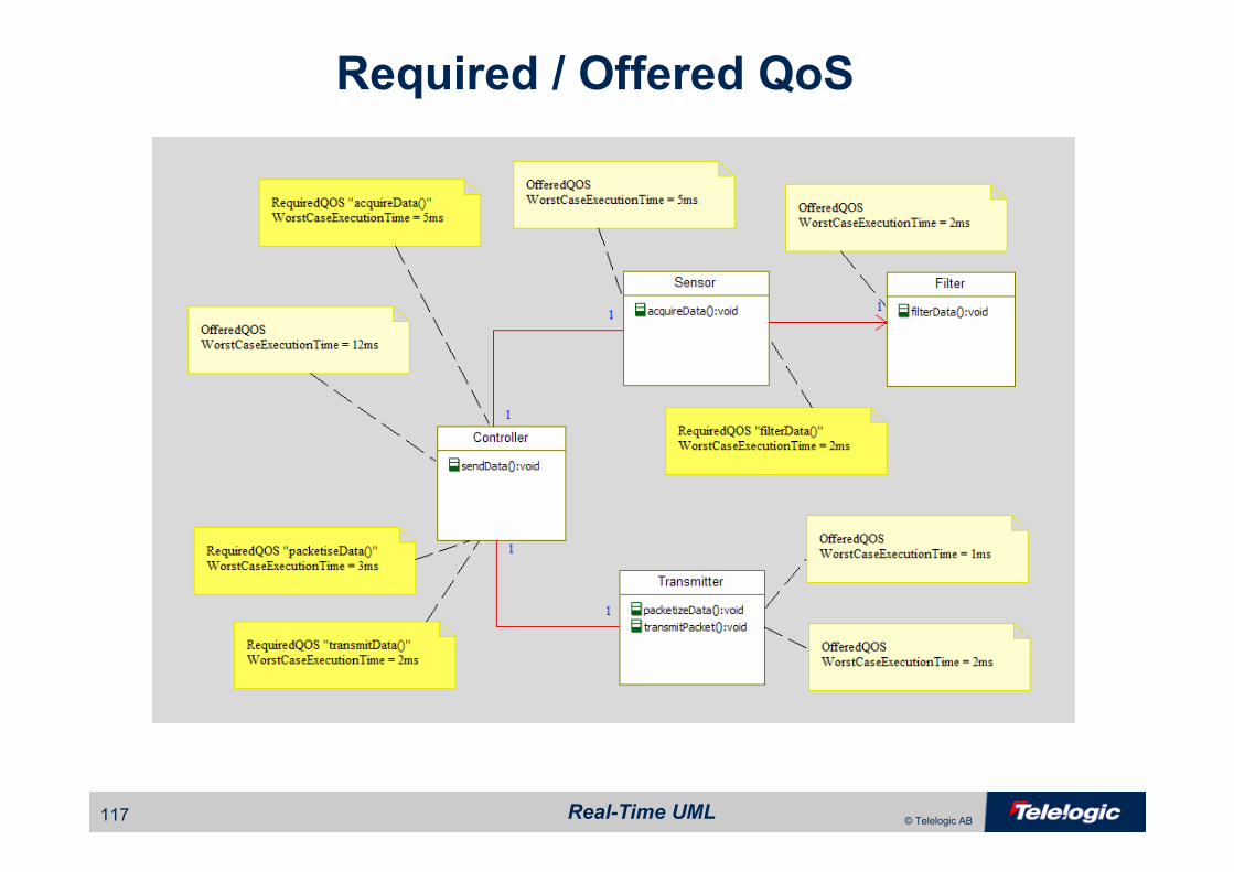
Required / Offered QoS
Real-Time UML117 © Telelogic AB
Required / Offered QoS

Real-Time UML118 © Telelogic AB
Deployment Architecture
• Maps software components and subsystems to hardware– Represents a device as a node
– Iconic stereotypes are common
• Identifies physical connections among devices– May be buses, networks, serial lines, etc
• Two primary strategies– Asymmetric
• Design-time mapping of software elements to HW
– Symmetric
• Dynamic run-time mapping of software elements to HW

Real-Time UML119 © Telelogic AB
Deployment Architecture
Real-Time UML120 © Telelogic AB
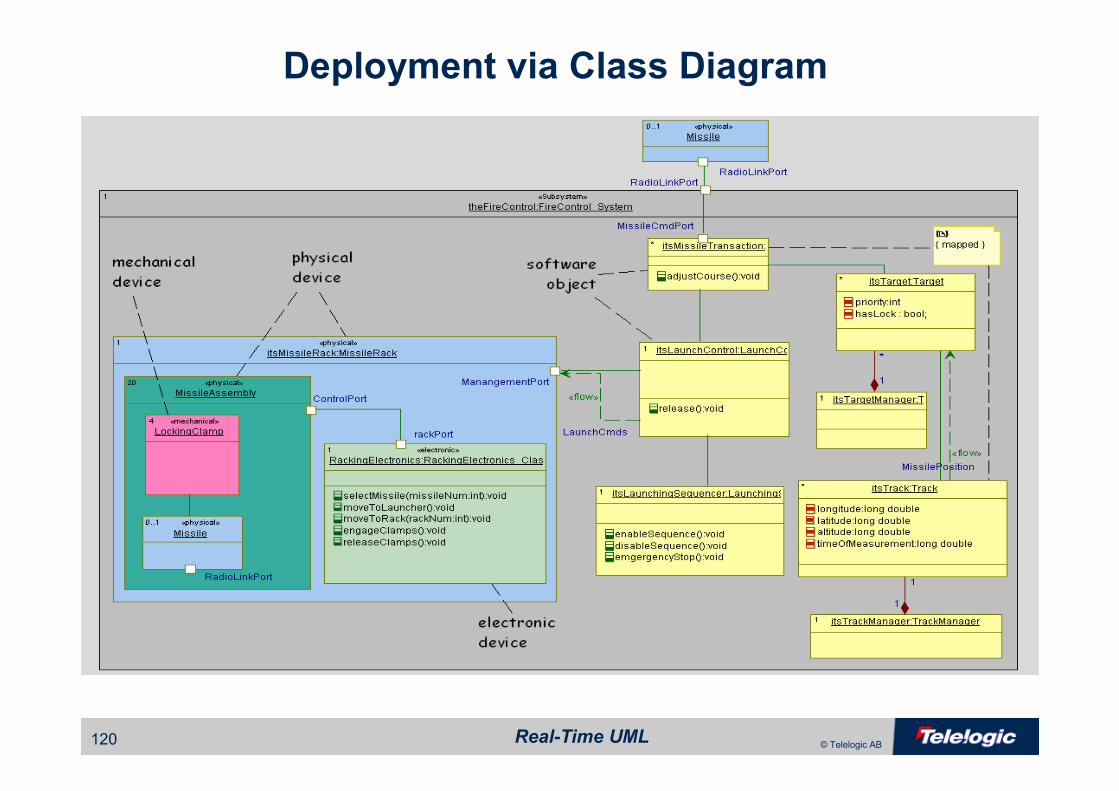
Deployment via Class Diagram
Real-Time UML121 © Telelogic AB
The UML Profile for The UML Profile for
Schedulability, Performance, and Schedulability, Performance, and
TimeTime
Real-Time UML122 © Telelogic AB
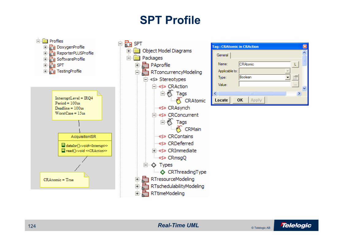
General Approach
• Use light-weight extensions to add standard modeling approaches and elements
– Stereotypes, e.g. resources
– Tagged values, e.g. QoS properties
• Divide submission into sub-profiles to allow easier comprehension and usage of relevant parts
Real-Time UML123 © Telelogic AB
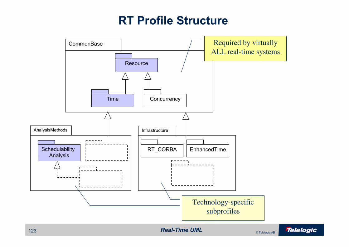
RT Profile Structure
CommonBase
Infrastructure
EnhancedTimeRT_CORBA
Resource
Time Concurrency
AnalysisMethods
SchedulabilityAnalysis
Required by virtually
ALL real-time systems
Technology-specific
subprofiles
Real-Time UML124 © Telelogic AB
SPT Profile

Real-Time UML125 © Telelogic AB
ExampleVS: VoltageSensor
Cooked1:
Waveform
Cooked2:
Waveform
Raw: Waveform
WFController1:
WaveformScaler
WFController1:
WaveformScaler
Display1:
WaveformView
Display1:
WaveformView
DataSample
0 .. 20,000
«SATrigger»
{ SAOccurrence = (periodic,
(50, 'ms')) }
«SAResponse»
{ SAPriority=100;
SAWorstCase=(2.5, 'ms');
SAAbsDeadline=(50, 'ms'); }
«SAResource»
{ SAAccessControl = PriorityInheritance; }
WaveformDisplaySystem «system»
void main()
«CRConcurrent»
{ CRMain="main"; }
«SATrigger»
{ SAOccurrence = (periodic, (10, 'ms')) }
«SAResponse»
{ SAPriority=10;
SABlocking=(1, 'ms');
SAWorstCase=(2, 'ms');
SAAbsDeadline=(10, 'ms'); }
«SATrigger»
{ SAOccurrence = (periodic,
(20, 'ms')) }
«SAResponse»
{ SAPriority=15;
SABlocking=(1, 'ms');
SAWorstCase=(5, 'ms');
SAAbsDeadline=(20, 'ms'); }
«SATrigger»
{ SAOccurrence = (periodic,
(50, 'ms')) }
«SAResponse»
{ SAPriority=100;
SAWorstCase=(2.5, 'ms');
SAAbsDeadline=(50, 'ms'); }
dataSample get(void);
void (dataSample);
«SAAction»
{ SAWorstCase = (0.2,'ms'); }
«SAAction»
{ SAWorstCase = (0.2,'ms'); }
«SATrigger»
{ SAOccurrence = (periodic,
(20, 'ms')) }
«SAResponse»
{ SAPriority=15;
SABlocking=(1, 'ms');
SAWorstCase=(5, 'ms');
SAAbsDeadline=(20, 'ms'); }
Real-Time UML126 © Telelogic AB
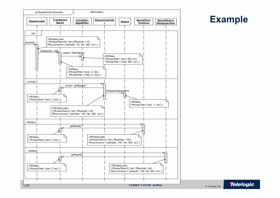
Examplesd EngineControl Scenario «PAContext»
Note; in this RTOS, higher values of the priority
property have low er execution priorityacquire()
:DopplerLight :EngineController
:EngineSpeedHistory:
HistogramView
smoother:DigitalFilter
SpeedView:TextView
TrainSpeed:
Speed
«PAOpenLoad»{ PArespTime=(20, 'ms'); PApriority = 10;
PAoccurrence = ('periodic', 10, 'ms', 500, 'us'); }
setSpeed(s: real);
«PAStep»{ PArespTime= ('ave', 2, 'ms');
PArespTIme = ('max, 4, 'ms'); }
speed = f ilterData(s)
par
«PAStep»{ PArespTime= ('ave', 500 'us');
PArespTIme = ('max, 800, 'us'); }
control()
actual = getSpeed()
setSpeed(adjustment)
«PAOpenLoad»
{ PArespTime=(5, 'ms'); PApriority = 20;PAoccurrence = ('periodic', 100, 'ms', 500, 'us'); }
«PAStep»
{ PArespTime= ('ave', 2 'ms'); }«PAStep»
{ PArespTime= ('ave', 1, 'ms'); }
display()
getSpeed()
«PAOpenLoad»
{ PArespTime=(3, 'ms'); PApriority = 100;
PAoccurrence = ('periodic', 100, 'ms', 500, 'us'); }
«PAStep»
{ PArespTime= ('ave', 2 'ms'); }
update()
getSpeed()
«PAOpenLoad»{ PArespTime=(5, 'ms'); PApriority = 40;
PAoccurrence = ('periodic', 100, 'ms', 500, 'us'); }
«PAStep»
{ PArespTime= ('ave', 2 'ms'); }

Real-Time UML127 © Telelogic AB
GIGO
• Select the appropriate stereotypes and tags of the schedulability model to match the kind of analysis desired
– Global RMA
• Elements: active objects, resources
• Tags: execution time, deadline, period, priority, blocking time, priority ceiling
– Detailed RMA
• Elements: active objects, resources, actions, events, scenarios, scenario
steps, messages
• Tags: execution time, deadline, period, priority, blocking time, priority ceiling
– Simulation
• Depends on particular approach
– etc

Real-Time UML128 © Telelogic AB
Model Processing
UML Modeling Tool Model Analysis Tool
−≤
+++
−
−∑ 12...max1
1
1
1
1 n
n
n
nj
j nT
B
T
B
T
C
Model Conversion
Inverse Model
Conversion
Modeler
User Model
Analysis Method Provider
Analytic Techinques
Validated User Model
Application System
Modeler
Analysis Configuration
Paramers
QoS Properties
Real-Time UML129 © Telelogic AB
HarmonyHarmony™™
Systems to Software Systems to Software
ProcessProcess
Real-Time UML130 © Telelogic AB
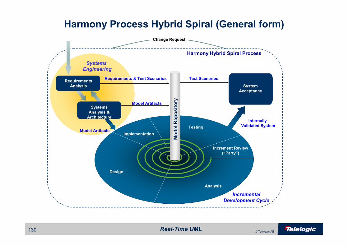
Harmony Process Hybrid Spiral (General form)
Analysis
Design
Implementation
Testing
Increment Review
(“Party”)
Incremental
Development Cycle
Requirements & Test Scenarios
System
Acceptance
Requirements
Analysis
Systems
Engineering
Change Request
Harmony Hybrid Spiral Process
Test Scenarios
Model Artifacts
Model Artifacts
Systems
Analysis &
Architecture
Model Repository
Internally
Validated System
Real-Time UML131 © Telelogic AB
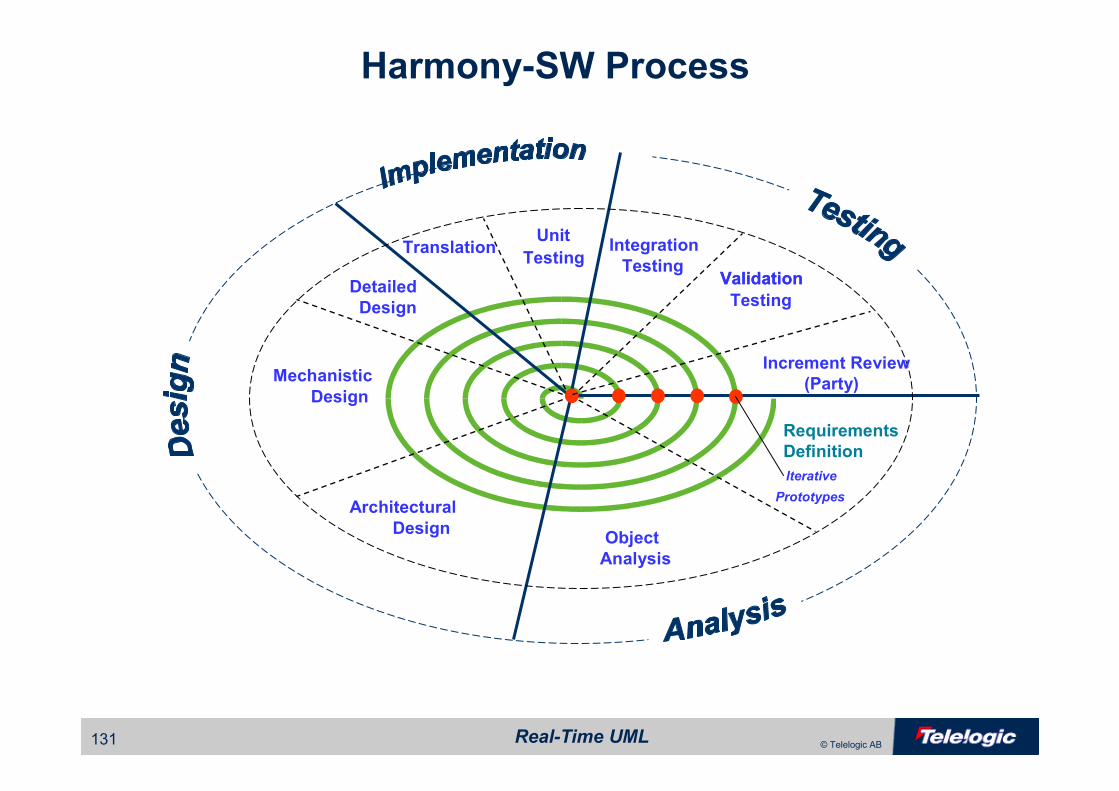
Harmony-SW Process
Mechanistic
Design
Detailed
Design
TranslationUnit
TestingIntegration
Testing
Iterative
PrototypesArchitectural
DesignObject
Analysis
Requirements
Definition
Validation
Testing
Validation
(Party)
Increment Review
Real-Time UML132 © Telelogic AB
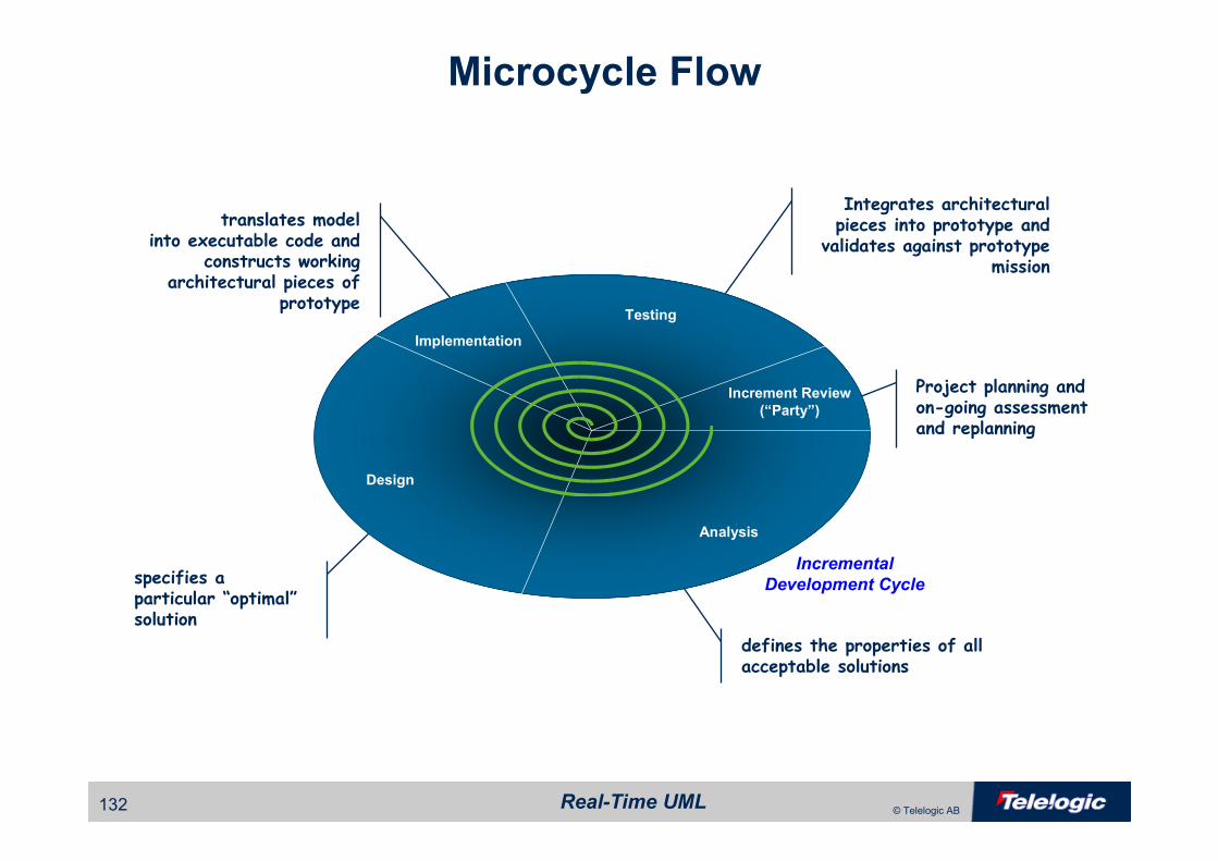
Microcycle Flow
defines the properties of all acceptable solutions
specifies aparticular “optimal”solution
translates modelinto executable code and
constructs working architectural pieces of
prototype
Integrates architectural pieces into prototype and
validates against prototype mission
Project planning and on-going assessment and replanning
Analysis
Design
Implementation
Testing
Increment Review
(“Party”)
Incremental
Development Cycle

Real-Time UML133 © Telelogic AB
Harmony Incremental Spiral Workflows
Real-Time UML134 © Telelogic AB
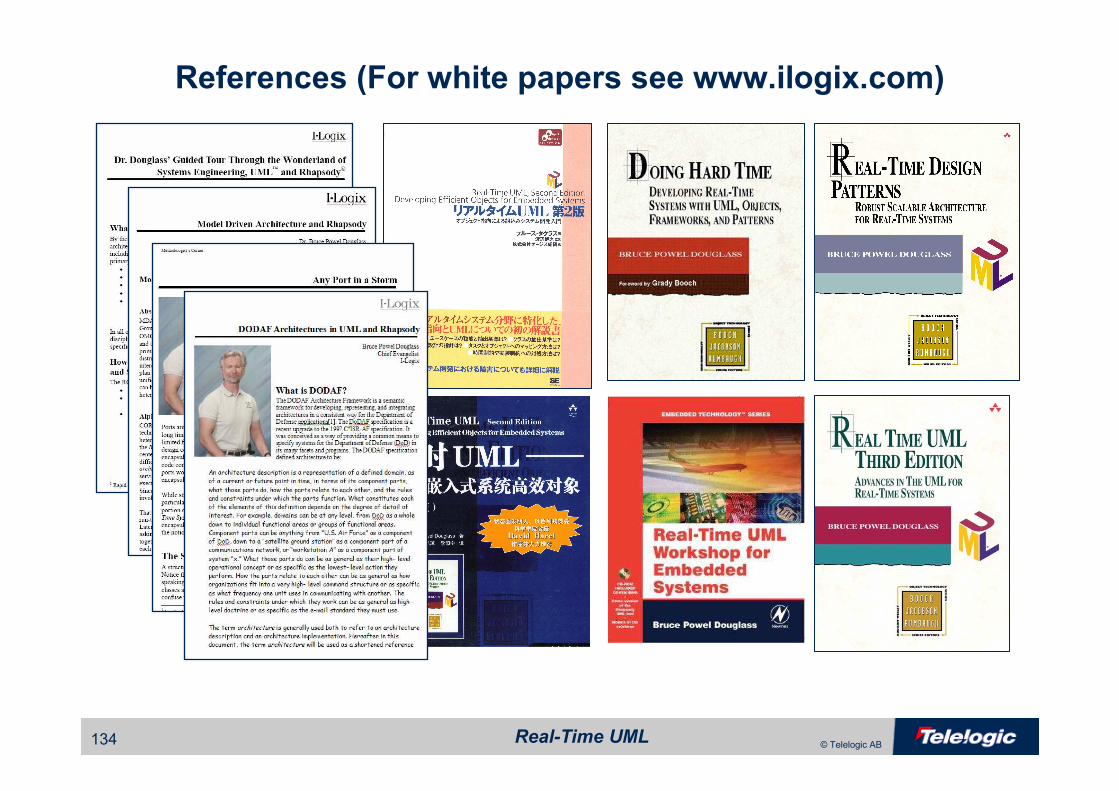
References (For white papers see www.ilogix.com)


![Falling in Love with Forms [Øredev 2015]](https://img.pdfslide.net/doc/110x75/58eec7431a28ab622e8b470d/falling-in-love-with-forms-oredev-2015.jpg)