Embed Size (px)
Citation preview
Licensed copy:Stourbridge College, 01/03/2010, Uncontrolled Copy, © BSI
BRITISH STANDARD
BS 6644:2005A1:2008+Specification for Installation of gas-fired hot water boilers of rated inputs between 70kW (net) and 1.8 MW (net) (2nd and 3rd family gases
ICS 91.140.65
���������������� ������������������������������� �������������
BS 6644:2005+A1:2008
Licensed copy:Stourbridge College, 01/03/2010, Uncontrolled Copy, © BSI
This British Standard was published under the authority of the Standards Policy and Strategy Committee on 8 July 2005
Second edition July 1990Third edition October 1991
First published March 1986
© BSI 2008
The following BSI references relate to the work on this standard:Committee reference GSE/30Draft for Development 03/310868 DC
ISBN 978 0 580 64905 9
Committees responsible for this British Standard
The preparation of this British Standard was entrusted to Technical Committee GSE/30, Gas installations (1st, 2nd and 3rd family gases), upon which the following bodies were represented:
Boiler and Radiator Manufacturers’ Association Ltd
British Flue and Chimney Manufacturers Association
BSI Consumer Policy Committee
Catering Equipment Suppliers’ Association
Centrica plc
Council for Registered Gas Installers
Department of Trade and Industry
Health and Safety Executive
Heating and Ventilating Contractors’ Association
ICOM Energy Association
Institute of Domestic Heating and Environmental Engineers
Institution of Gas Engineers and Managers
L P Gas Association
Society of British Gas Industries
Co-opted members
Amendments issued since publication
Amd. No. Date Text affected
AMD1 30 November 2008
See foreword
+A1:2008BS 6644:2005
© BSI 2008Licensed copy:Stourbridge College, 01/03/2010, Uncontrolled Copy, © BSI
ContentsPage
Committees responsible Inside front coverForeword ii
1 Scope 12 Normative references 13 Terms and definitions 34 Competence and design considerations 55 Selection of boiler, materials and components 66 Installation 87 Inspection, commissioning and servicing 29
Annex A (Informative) Basis for the provision of combustion and cooling air to boiler houses and rooms in which commercial boilers are installed in accordance with this standard 32Annex B (Informative) Fan diluted flues 36Annex C (Informative) Checks to be carried out on the boiler prior to commissioning 37Annex D (Informative) Typical live run checks 37Annex E (Normative) Combustion products analysis 38
Bibliography 40
Figure 1 — Typical balanced compartment ventilation location 22Figure 2 — Siting of a natural draught flue terminal 26Figure B.1 — Uncorrected chimney heights 36
Table 1 — Safety valve sizes (open vented systems only) 10Table 2 — Cold feed pipe sizes 12Table 3 — Open vent pipe sizes 12Table 4 — Minimum air vent free-area for room-sealed boilers installed in an enclosure 19Table 5 — Mechanical ventilation flow rates 21Table A.1 — Cooling air for a boiler not fitted with a draught diverter 33Table A.2 — Cooling air for a boiler fitted with a draught diverter 33Table A.3 — Natural ventilation for a boiler not fitted with a draught diverter 34Table A.4 — Natural ventilation for a boiler fitted with a draught diverter 34Table A.5 — Mechanical ventilation flow rates 35Table E.1 — Concentrations of (CO2)N in Group H, P and B gases (percentage) 39
Annex F (Informative) Best practice guide to the dispersion of combustion products 39
i
ii
+A1:2008BS 6644:2005
Licensed copy:Stourbridge College, 01/03/2010, Uncontrolled Copy, © BSI
Foreword
This publication does not purport to include all the necessary provisions of a contract. Users are responsible for its correct application.
The Gas Safety (Installation and Use) Regulations 1998 [1]
The Gas Safety (Installation and Use) (Northern Ireland) Regulations 2004 [2]
The Gas Appliances (Safety) Regulations 1995 [3]
The Boiler (Efficiency) Regulations 1993, as amended [4]
The Building Regulations 2000, as amended [5]
The Building (Scotland) Regulations 2004 [6]
The Building Regulations (Northern Ireland) Statutory Rules 2000 [7]
The Pressure Equipment Regulations 1999 [8]
The Water Supply (Water fittings) Regulations 1999 [9]
The Health and Safety at Work etc. Act 1974 [10]
The Electricity at Work Regulations 1989 [11]
Clean Air Act 1993 [12]
The Asbestos (Prohibitions) Regulations 1992, as amended [13]
The Dangerous Substances and Explosive Atmospheres Regulations 2002 [14]
Summary of pagesThis document comprises a front cover, an inside front cover, pages i to ii,
The start and finish of text introduced or altered by Amendment No. 1
Compliance with a British Standard cannot confer immunity from legal obligations.
The Environment Act 1995 [40]
!"
! "
In particular, attention is drawn to the following legislation.
BS 6644:2005+A1:2008 supersedes BS 6644:2005, which is withdrawn.This British Standard has been prepared by Technical Committee GSE/30.
is indicated in the text by tags .
document was last issued.
© BSI 2008
The BSI copyright notice displayed in this document indicates when the
pages 1 to 46, an inside back cover and a back cover.
+A1:2008BS 6644:2005
Licensed copy:Stourbridge College, 01/03/2010, Uncontrolled Copy, © BSI
1 ScopeThis British Standard specifies requirements for the installation, including design, inspection and commissioning, of gas-fired hot water boilers of net rated heat inputs exceeding 70 kW but not exceeding a net heat input of 1.8 MW. Groups of boilers with individual net heat inputs of 70 kW or less, but with aggregate net heat inputs in excess of 70 kW, are also covered by this standard.
This standard is applicable to the installation of boilers that are designed to utilize normally distributed gases of Group H of the second family (e.g. natural gas), and gases of Group P (e.g. propane) and Group B (e.g. butane) of the third family. For the purposes of this installation standard, LPG/air mixtures are regarded as third family gases.
This standard is applicable to the installation of gas-fired hot water boilers within the scope of:
a) for boilers supplied as a complete assembly, BS EN 656 or BS 5978 (all parts);
b) for boilers supplied as a complete assembly and used in multiple boiler installations whose total net heat input exceeds 70 kW, BS EN 297, BS EN 483, or BS EN 677;
c) for boilers and burners delivered separately and assembled on site:
1) the boiler shell, BS EN 303-1, BS EN 12952, BS EN 12953 BS 779, BS 855, or BS 2790;
2) the burner, BS EN 676;
3) the assembly, BS EN 303-3 or BS 5987-1 and BS 5978-3.NOTE 1 For the purposes of this standard, installation includes design, inspection and commissioning. It is recognised that each of these require different levels of competence (see 4.1.2). Where all of these tasks are performed by same person, that person has to have the necessary levels of competence for each task.
NOTE 2 Although this standard does not contain any requirements for industrial processes, the general principles can be applied.
NOTE 3 The general principles of this standard with respect to hot water circuits can be used for boilers exceeding 1.8 MW net heat input (2 MW gross heat input). For installations exceeding 1.8 MW net heat input, see IGE/UP/10 [15].
NOTE 4 The ratio of gross to net heat input is approximately 1.11:1 for Group H (natural gas), 1.09:1 for Group P (propane) and 1.08:1 for group B (butane).
It is also applicable to installations that have been converted from burning other fuels to gas-firing.
This standard is not applicable to:
a) the installation of any heating or hot water supply system associated with the boiler installation,
b) the installation of gas cushion systems (non diaphragm expansion vessels) intended to pressurize the hot water circuit, or
c) installations in hazardous areas, as defined in The Dangerous Substances and Explosive Atmospheres Regulations [14].
2 Normative referencesThe following referenced documents are indispensable for the application of this document. For dated references, only the edition cited applies. For undated references, the latest edition of the referenced document (including any amendments) applies.
BS 779, Specification for cast iron boilers for central heating and indirect hot water supply (rated output 44 kW and above).
BS 855, Specification for welded steel boilers for central heating and indirect hot water supply (rated output 44 kW to 3 MW).
BS 1212-1, Float operated valves — Part 1: Specification for piston type float operated valves (copper alloy body) (excluding floats).
BS 1212-2, Float operated valves — Part 2: Specification for diaphragm type float operated valves (copper alloy body) (excluding float).
BS 1212-3, Float operated valves — Part 3: Specification for diaphragm type float operated valves (plastic bodied) for cold water services only (excluding floats).
BS 1387, Specification for screwed and socketed steel tubes and tubulars and for plain end steel tubes suitable for welding or for screwing to BS 21 pipe threads.
1© BSI 2008
+A1:2008BS 6644:2005
Licensed copy:Stourbridge College, 01/03/2010, Uncontrolled Copy, © BSI
BS 2790, Specification for design and manufacture of shell boilers of welded construction.
BS 4076, Specification for steel chimneys.
BS 4814, Specification for expansion vessels using an internal diaphragm, for sealed hot water heating systems.
BS 5854:1980, Code of practice for flues and flue structures in buildings.
BS 5978-1, Safety and performance of gas-fired boilers hot water boilers (60 kW to 2 MW input) — Part 1: Specification for general requirements.
BS 5978-2, Safety and performance of gas-fired boilers hot water boilers (60 kW to 2 MW input) — Part 2: Specification for additional requirements for boilers with atmospheric burners.
BS 5978-3, Safety and performance of gas-fired boilers hot water boilers (60 kW to 2 MW input) — Part 3: Specification for additional requirements for boilers with forced or induced draught burners.
BS 6282-1:1982, Devices with moving parts for the prevention of contamination of water by backflow — Part 1: Specification for check valves of nominal size up to and including DN 54.
BS 7671, Requirements for electrical installations — IEE Wiring Regulations.
BS EN 297, Gas-fired central heating boilers — Type B11 and B11BS boilers fitted with atmospheric burners of nominal heat input not exceeding 70 kW.
BS EN 303-1, Heating boilers — Part 1: Heating boilers with forced draught burners — Terminology, general requirements, testing and marking.
BS EN 303-3, Heating boilers — Part 3: Gas-fired central heating boilers — Assembly comprising a boiler body and a forced draught burner.
BS EN 483, Gas-fired central heating boilers — Type C boilers of nominal heat input not exceeding 70 kW.
BS EN 656, Gas-fired central heating boilers — Type B boilers of nominal heat input exceeding 70 kW but not exceeding 300 kW.
BS EN 676, Automatic forced draught burners for gaseous fuels.
BS EN 677, Gas-fired central heating boilers — Specific requirements for condensing boilers with a nominal heat input not exceeding 70 kW.
BS EN 1567, Building valves — Water pressure reducing valves and combination water reducing valves — Requirements and tests.
BS EN 1856-1, Chimneys — Requirements for metal chimneys — Part 1: System chimney products.
BS EN 1856-2, Chimneys — Requirements for metal chimneys — Part 2: Metal liners and connecting flue pipes.
BS EN 12952 (all parts), Water tube boilers and auxiliary installation.
BS EN 12953 (all parts), Shell boilers.
BS EN 13076, Devices to prevent pollution by backflow of potable water — Unrestricted air gap — Family A, type A.
BS EN 13077, Devices to prevent pollution by backflow of potable water — Air gap with non-circular overflow (unrestricted) — Family A, type B.
BS EN ISO 4126-1, Safety devices for protection against excessive pressure — Part 1: Safety valves.
BS EN ISO 10380:2003, Pipework — Corrugated metal hoses and hose assemblies.
2 © BSI 2008
+A1:2008BS 6644:2005
Licensed copy:Stourbridge College, 01/03/2010, Uncontrolled Copy, © BSI
3 Terms and definitionsFor the purposes of this British Standard, the definitions given in BS EN 297, BS EN 483, BS EN 677, BS EN 656, BS EN 303-1, BS EN 303-3, BS EN 12952 (all parts), BS EN 125953-1, BS 5978 (all parts) and the following apply.
3.1 automatic natural draught burnernatural draught burner in which, starting from the completely shut-down condition, the start-gas flame is established and the main gas valve(s) actuated by the control without manual interventionNOTE Automatic burners can have pilots which are either interrupted or intermittent.
3.2 non-automatic natural draught burnernatural draught burner with a permanent, manually ignited pilot
3.3 bank of boilersgroup of two or more boilers connected to common flow and return pipes, in which the individual boilers cannot be separately isolated
3.4 boiler housededicated building for the installation of boilers and ancillary boiler plant
3.5 boiler roomdedicated room within a building for the installation of boilers and ancillary boiler plant
3.6 balanced compartmentboiler house/room or enclosure for one or more gas appliances, specifically designed to draw its combustion air from a point adjacent to the point at which the products of combustion are discharged, the inlet and outlet being so disposed that wind effects are substantially balanced
3.7 condensing boilerboiler in which, under normal operating conditions, the water vapour in the combustion products is totally or partially condensed in order to make use of the latent heat in the water vapour for heating purposes
3.8 coefficient of discharge
value of actual flowing capacity (from tests) divided by the theoretical flowing capacity (from calculations)
3.9 derated coefficient of discharge Kdrcoefficient of discharge, Kd, multiplied by 0.9, i.e. Kdr = Kd × 0.9
3.10 enclosure
maintenance via external access
3.11 free-areaunobstructed cross-sectional area of a grille, louvre or duct calculated as the sum of the cross-sectional areas of all unobstructed apertures measured through the plane of minimum area and at right angles to the air flow within the apertures
! d
pace in which a boiler(s) is installed, which is not large enough to permit access for work other than s
"K
3© BSI 2008
+A1:2008BS 6644:2005
Licensed copy:Stourbridge College, 01/03/2010, Uncontrolled Copy, © BSI
3.12 grillenon-closable fitment for an opening through which air passes
3.13 maximum allowable temperaturetemperature at which the safety temperature limiter causes the boiler to go to non-volatile lockoutNOTE This definition has been adapted from that given by the Pressure Equipment Regulations 1999 [8].
3.14 maximum allowable pressuremaximum pressure for which the boiler is designed as specified by the manufacturerNOTE The lowest maximum allowable pressure of any component of the system determines the maximum allowable pressure of the system itself.
3.15 modular boilerboiler consisting of two or more generally identical modules, each of which consists of a heat exchanger, burner, and control and safety devicesNOTE The assembly has a single flue outlet, a common gas connection, a common electricity supply connection and common flow and return water connections. Each module is capable of independent operation. [BS EN 656:2000, 3.2.4].
3.16 modular systemsystem consisting of an assembly of two or more generally identical boilers sharing the same heating load
3.17 open-flue boilerboiler designed to be connected to a flue system that evacuates the products of combustion to the outside air and which draws combustion air directly from the room or enclosure containing the applianceNOTE Under European classification (see PD 1749), known as a Type B boiler.
3.18 operating pressuremaximum pressure under normal operating conditions
3.19 plant roomroom in a building which houses plant or machinery
3.20 room-sealed boilerboiler whose combustion system is sealed from the room in which the boiler is located, and which obtains air for combustion from the open air outside the premises and which vents the products of combustion directly to open air outside the premisesNOTE Under European classification (see PD 1749), known as a Type C boiler.
3.21 safety temperature limiterdevice that causes safety shut down and non-volatile lockout so as to prevent the water temperature exceeding a pre-set limitNOTE The maximum “pre-set” limit is the “maximum allowable temperature”.
3.22 safety valvespring-loaded automatic valve fitted on, or adjacent to, a boiler for relieving the build-up of excess pressure
4 © BSI 2008
+A1:2008BS 6644:2005
Licensed copy:Stourbridge College, 01/03/2010, Uncontrolled Copy, © BSI
4 Competence and design considerations
4.1 Competence
4.1.1 Persons who design the heating system or installation shall have a knowledge and understanding of the standards and regulations that apply to ensure that any completed plans will produce a safe and satisfactory installation.
4.1.2 Persons carrying out the installation, commissioning and maintenance shall be competent.
COMMENTARY AND RECOMMENDATIONS ON 4.1.2
Work covered by the Gas Safety (Installation and Use) Regulations (GSIUR) [1] has to be carried out by a business or self-employed person, who is a “member of a class of persons approved for the time being by the Health and Safety Executive (HSE)”.
At the time of publication, the body with HSE approval to operate and maintain a register of businesses who are “members of a class of persons” is the Council for Registered Gas Installers (CORGI).
Persons deemed competent to carry gas work are those who hold a certificate of gas safety competence acceptable to CORGI, which includes (without limitation) the Accredited Certification Scheme (ACS) and the Gas Services S/NVQ that has been aligned with ACS.
The commissioning engineer might not be the person responsible for the installation work, and separate competence levels need to be assured. The boilers to which this standard refers incorporate varied burner and control technology. It is essential that the inspecting and/or commissioning engineer is familiar with the type of burner and control fitted to the boiler(s).
The burner can be natural draught (with or without a fan), pre-mix, forced draught or dual fuel. The control may be on/off, multi-staged or fully modulating. Some burners have variable speed fans, oxygen trim, microprocessor control, and/or technology for the reduction of oxides of nitrogen (NOX). The manufacturer’s instruction should be consulted to ensure that the equipment is within the inspecting and/or commissioning engineer’s competence.
In premises not covered by the GSIUR competence in gas work may be demonstrated by either satisfying the ACS scheme or by virtue of training to COP 20 (HSC: ACOP Standard of training in safe gas installations, 1987 [16]).
4.2 Design considerations
The design shall be such that it permits installation to proceed in accordance with the boiler manufacturer’s instructions. In case of doubt, the designer shall consult the boiler manufacturer.
The following shall be ascertained before detailed planning of the installation begins:
a) the type of building in which the boiler is to be installed, its form of construction and its suitability for the particular boiler installation, perhaps by application of risk assessment procedures;
b) the sizes and purposes of rooms and working areas;
c) the size, height and route of the flue and the position of the termination, including the possible consequences of any pluming, together with the materials of construction;
d) the availability of adequate air for combustion and ventilation;
e) heat losses and heat gains;
f) gas pressures and the availability of supplies;
g) the feasibility of providing a gas supply where a gas supply does not already exist;
h) the available electrical supplies;
! "
NOTE Guidance on chimney and flue design is given in Annex F and in Appendix 3 of IGE/UP/10 [15].
j) the location and routing of any drains for the removal of condensate (see 6.10.1.3);
! "i) the applicable legislation and any local bye-laws;
5© BSI 2008
+A1:2008BS 6644:2005
Licensed copy:Stourbridge College, 01/03/2010, Uncontrolled Copy, © BSI
k) transmission of noise and vibration (guidance on acceptable noise levels is given in the CIBSE Guide B [17] and the HSE’s “Code of practice for reducing the exposure of employed persons to noise” [18] — specialist consultancy advice might be necessary); and
l) whether the hot water system’s location is classified as a hazardous area, as defined in The Dangerous Substances and Explosive Atmospheres Regulations [14].
COMMENTARY AND RECOMMENDATIONS ON 4.2
Collaboration is essential between those concerned with the design of the hot water boiler and its installation, both at the planning stage and during the execution of the work.
The designer should draw to the attention of the owner or occupier of the premises in which the hot water boiler is to be installed their responsibility to ensure that:
a) the local authority is consulted with regard to building regulations and planning application
b) the fire authority and/or the enforcing authority under the Health and Safety at Work etc. Act 1974 [10], as appropriate, is consulted in respect of fire precautions;
c) the fire insurers are notified of any proposed changes in the means of heating;
d) the responsible gas conveyor is advised of the proposed installation of any gas booster or compressor which is either part of the boiler or an addition to it;
e) the gas conveyor is consulted to ensure that the gas service is suitable to supply all of the gas to the complete installation at the correct pressure, including any existing load.
5 Selection of boiler, materials and components
5.1 General
The installer shall check that any new boiler is CE marked, where appropriate.
Any individual boiler of rated net heat input not exceeding 70 kW selected for installation as part of a modular system of boilers exceeding a net heat input of 70 kW shall incorporate a safety temperature limiter.
The boiler shall be installed in accordance with the boiler manufacturer’s instructions.
The installer shall check the data provided with the boiler to confirm that the boiler is appropriate for the installation, and shall confirm the basis on which the nominal heat input, or heat input rating, is quoted, i.e. gross or net (see Scope, NOTE 4)
The boiler shall only be connected to, and supplied with, the gas for which it was designed.
The installer shall ensure that the boiler is correctly adjusted in accordance with the manufacturer’s instructions. Conversion to another gas, if necessary, shall be carried out strictly in accordance with the boiler manufacturer’s instructions, using the manufacturer’s supplied kit of parts.
The installer shall only select external control devices of a type recommended by the boiler manufacturer. In case of doubt, the boiler manufacturer shall be consulted.
COMMENTARY AND RECOMMENDATIONS ON 5.1
The HSE publication, L56: “Safety in the installation and use of gas systems and appliances” [19] should be consulted.
Of the boilers covered by this standard, new boilers with a normal operating temperature not exceeding 105 °C fall within the scope of the European Gas Appliances Directive [20], implemented in the UK by the Gas Appliances (Safety) Regulations [3], which requires such boilers to be CE marked. Those with a heat output not exceeding 400 kW are also covered by the Boiler (Efficiency) Regulations 1993 [4].
New boilers with a maximum allowable temperature exceeding 110 °C are required to be CE marked in accordance with the Pressure Equipment Directive [21], implemented in the UK by the Pressure Equipment Regulations 1999 [8]. Boilers with a maximum operating temperature exceeding 105 °C, but a maximum allowable temperature not exceeding 110 °C, are subject, at least, to sound engineering practice in accordance with the Pressure Equipment Directive [21].
requirements , including the approval of the chimney height if the net input of the boiler(s) is above330 kW (366.4 kW gross) for 2nd family gases or 338 kW (366.4 kW gross) for 3rd family gases and the
!
"impact of all emissions on local air quality;
6 © BSI 2008
+A1:2008BS 6644:2005
Licensed copy:Stourbridge College, 01/03/2010, Uncontrolled Copy, © BSI
5.2 Condensing boilers
A condensing boiler shall be installed in accordance with the manufacturer’s instructions, paying particular attention to any instructions concerning the management of condensate, which can have implications for the siting of the boiler and/or its flue terminal.
Due to the tendency of condensing boilers to form a plume of water vapour from the flue terminal, the terminal shall be sited such that the wet combustion products do not cause damage or nuisance.
COMMENTARY AND RECOMMENDATIONS ON 5.2
The manufacturer’s instructions should be consulted for any particular requirements for the condensing boiler, e.g. a means for the disposal of condensate.
When siting a condensing boiler, early consideration should be given to the following.
a) The effect of wind conditions and the dispersal of the plume relative to adjacent wall surfaces, openable windows and neighbouring buildings might require greater separation distances to prevent nuisance and ingress.
b) The positioning and termination of the condensate drain pipe.
The condensate pipe should, ideally, run and terminate internally to a soil and vent stack or a waste pipe. Alternatively, the condensate can be discharged into the rainwater system or a purpose-made soakaway.
All connecting drainage pipework should have a fall of at least 2.5° to the horizontal, or approximately 50 mm per metre of pipe run. If the drainage pipe has an external run the pipe should be insulated against frost. It should be noted that the connection of a condensate pipe to a drain might be subject to building controls.
c) The choice of condensate drainage pipe.
The condensate drainage pipe should be run in a standard drain pipe material, e.g. polyvinyl chloride (PVC), unplasticized polyvinyl chloride (PVC-U), acrylonitrile-butadiene-styrene (ABS), polypropylene polypropene (PP) or cross-linked polyvinyl chloride (PVC-C). Any internal pipework should be of a diameter specified in the boiler manufacturer’s instructions. Any external pipework should be kept to a minimum length with a minimum diameter of 22 mm which might be greater than that recommended by the manufacturer in order to minimize the effects of freezing.
5.3 Materials and components
Materials and components containing asbestos shall not be selected for use in the installation. High melting point solders incorporating cadmium shall not be used.
Only components suitable for the temperatures and pressures to which they are likely to be subjected when installed shall be selected for installation.
The maximum allowable temperature of a boiler selected for installation shall not exceed the maximum allowable temperature of any component of an existing heating system.
The maximum allowable pressure of each component in the heating system, including the boiler, shall be at least that at which the safety valve lifts.
COMMENTARY AND RECOMMENDATIONS ON 5.3
For existing flue systems containing asbestos, see Commentary and Recommendations on 6.10.1.1.
These requirements are particularly relevant when the maximum allowable temperature of the boiler used is in excess of 110 °C. See also BS 6880-1:1988, 3.4.5.2, and BS 6880-2:1988, 4.4.2.2 and 4.5.3.
The maximum setting of any temperature controller should be such that the fuel supply is cut off when the water at or near the boiler flow outlet rises to its predetermined temperature such that a margin of at least 17K exists below the temperature of saturated steam corresponding with the pressure at the highest point of the circulating system above the boiler. The setting of any safety temperature limiter should be such that the fuel supply is cut off when the temperature of water at or near the boiler flow outlet rises to a predetermined temperature providing a margin below the temperature of saturated steam corresponding with the pressure at the highest point of the circulating system above the boiler. This margin should be at least 6K. This control should be of the lock-out type requiring manual resetting.
7© BSI 2008
+A1:2008BS 6644:2005
Licensed copy:Stourbridge College, 01/03/2010, Uncontrolled Copy, © BSI
6 Installation
6.1 Siting of the boiler
6.1.1 The manufacturer’s instructions and associated data sheets shall be consulted on the siting of boilers.
6.1.2 If the boiler is to be installed in a purpose-constructed boiler room, the room shall conform to the requirements of 6.2.
COMMENTARY AND RECOMMENDATIONS ON 6.1.2
It is desirable that consideration always be given to the installation of boilers in purpose-constructed boiler rooms.
6.1.3 Where a purpose-constructed boiler room is not available, measures shall be taken to protect the boiler from damage, unauthorized interference or access and to prevent extraneous material from encroaching on the manufacturer’s recommended clearances.
6.1.4 In accordance with the manufacturer’s instructions, space shall be allowed and means shall be provided to give ready access for installing, operating, servicing and replacing the burner(s), controls, flue ways, waterways and any other parts that require regular attention.
COMMENTARY AND RECOMMENDATIONS ON 6.1.4
Consideration should be given to the provision of adequate means of access to permit replacement of the boiler. This is particularly important in the case of roof-top and basement installations.
6.1.5 Clearance between the boiler and its flue and any combustible material shall be in accordance with the manufacturer’s instructions and shall conform to 6.10.9.
6.1.6 The boiler installation shall be so designed that it does not cause adjacent spaces to exceed their design temperatures during operation of the boiler.
6.1.7 Boilers shall only be sited on floors and walls capable of:
a) withstanding temperatures of at least 65 °C, and
b) supporting the boilers when filled with water.
If a specially prepared boiler base is required, it shall be in accordance with the manufacturer’s instructions.
COMMENTARY AND RECOMMENDATIONS ON 6.1.7
The design of the boiler base requires consideration in relation to the heat losses, the number of boilers, their distance apart, their hearth areas and shapes.
The manufacturer’s instructions should be consulted as to whether special protection is required.
6.1.8 Means shall be provided for the disposal of water when the system is drained. Such means shall be readily accessible.
6.1.9 Boilers sited at or below ground level and in low-lying areas shall be provided with protection from the effects of flooding.
6.1.10 Boilers fired by 3rd family gases shall not be installed below ground level, e.g. in cellars or basements.
COMMENTARY AND RECOMMENDATIONS ON 6.1.10
This does not preclude the installation of such appliances into rooms which are low level with respect to one side of the building but open to ground level on the opposite side. In all cases, adequate low level ventilation to the outside is essential.
6.1.11 For boilers installed on roof-tops or intermediate floors or in multi-storey buildings, precautions shall be taken to protect the buildings and the boiler houses against the effects of any water leakage from the boiler installations.
6.2 Boiler rooms
6.2.1 If a boiler is to be installed in a boiler room, it shall only be installed in a boiler room which has been constructed, or adapted to conform to 6.2.2 to 6.2.5.
8 © BSI 2008
+A1:2008BS 6644:2005
Licensed copy:Stourbridge College, 01/03/2010, Uncontrolled Copy, © BSI
6.2.2 Routes shall be provided for ready access to and egress from boiler rooms at all times.
COMMENTARY AND RECOMMENDATIONS ON 6.2.2
Access to boiler installations should preferably be from outside the building.
6.2.3 Any means of egress from the boiler room shall be readily openable from inside the room without the aid of a key and open in the direction of the escape route.
COMMENTARY AND RECOMMENDATIONS ON 6.2.3
The distance from any point within the boiler room to the nearest means of egress should not exceed 12 m. (For information on fire precautions in buildings, see BS 5588.)
6.2.4 Where a boiler(s) is operated on 3rd family gases, the boiler room shall not have any openings to an immediately adjacent part of the building which is below ground level. Low level ventilation shall be fitted to connected spaces below the location of boilers fired by 3rd family gases.
6.2.5 Permanent electric lighting shall be provided for the boiler room to ensure safe working conditions.
6.3 Equipment in the water circuit
6.3.1 Isolation of the water supply
6.3.1.1 If not supplied with the boiler, a means shall be provided for isolating the water supply to the boiler. In the case of water connections to modular boilers this applies to each bank of modules.
6.3.1.2 Valves required to isolate boilers from the system shall be fitted such that isolation of the water supply is achieved safely.
COMMENTARY AND RECOMMENDATIONS ON 6.3.1.2
Three-way valves may be used so that, with the valve isolating the boiler from the system, the boiler flow is open to the outside atmosphere through the third port (see also 6.3.5.2.2.5).
6.3.2 Multiple boilers
Every boiler connected in parallel to a common flow and common return manifolds to form a multiple boiler installation shall be capable of isolation from the water system.
6.3.3 Modular boilers
In the case of modular boiler installations water isolating valves shall be fitted on the common flow and return manifolds of each bank of modules.
COMMENTARY AND RECOMMENDATIONS ON 6.3.3
Alternatively, this requirement may be satisfied by the fitting of isolating valves on each module of the modular installation.
6.3.4 Safety valves
6.3.4.1 Single boiler installations
6.3.4.1.1 General
6.3.4.1.1.1 Unless a safety valve(s) is already fitted, the boiler shall be provided with a safety valve(s) conforming to BS EN ISO 4126-1 and set to lift at a pressure not exceeding the maximum allowable pressure of any component of the heating system.
COMMENTARY AND RECOMMENDATIONS ON 6.3.4.1.1.1
An additional safety valve should be fitted to the secondary heat exchanger of a condensing boiler when it is connected to a heating circuit separate from the primary heat exchanger. The manufacturer’s installation instructions should be consulted.
6.3.4.1.1.2 The safety valve(s) shall be either:
a) attached directly to the boiler; or
b) fitted to the shortest possible straight length of pipe rising vertically from the boiler.
9© BSI 2008
+A1:2008BS 6644:2005
Licensed copy:Stourbridge College, 01/03/2010, Uncontrolled Copy, © BSI
6.3.4.1.1.3 Where the safety valve(s) is not fitted directly to the boiler, the pipe on which the valve(s) is mounted shall have an internal diameter not less than the bore of the valve or an internal cross-sectional area not less than the aggregate area of all the valves mounted upon it.
No other valve or cock shall be fitted between the safety valve(s) and the boiler, nor shall the pipe be used for any other purpose.
COMMENTARY AND RECOMMENDATIONS ON 6.3.4.1.1.2 AND 6.3.4.1.1.3
The fitting of the safety valve(s) directly to the boiler is preferred wherever possible.
6.3.4.1.2 Sizing of safety valves
6.3.4.1.2.1 Where a safety valve(s) is fitted in accordance with the manufacturer’s instructions, this shall be sized on the basis of the individual boiler rating or, for banks of boilers, the total rated output of each bank of boilers.
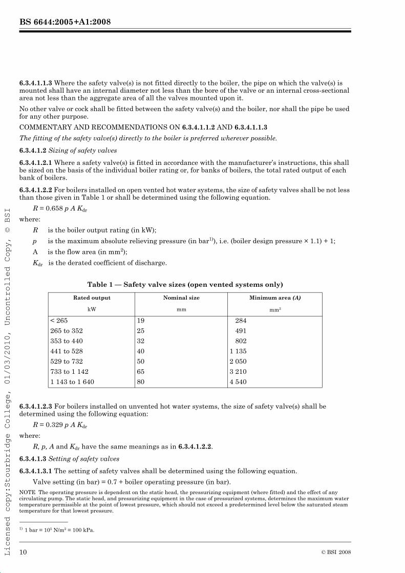
6.3.4.1.2.2 For boilers installed on open vented hot water systems, the size of safety valves shall be not less than those given in Table 1 or shall be determined using the following equation.
R = 0.658 p A Kdr
where:
R is the boiler output rating (in kW);
p is the maximum absolute relieving pressure (in bar1)), i.e. (boiler design pressure × 1.1) + 1;
A is the flow area (in mm2);
Kdr is the derated coefficient of discharge.
Table 1 — Safety valve sizes (open vented systems only)
6.3.4.1.2.3 For boilers installed on unvented hot water systems, the size of safety valve(s) shall be determined using the following equation:
R = 0.329 p A Kdr
where:
R, p, A and Kdr have the same meanings as in 6.3.4.1.2.2.
6.3.4.1.3 Setting of safety valves
6.3.4.1.3.1 The setting of safety valves shall be determined using the following equation.
Valve setting (in bar) = 0.7 + boiler operating pressure (in bar).NOTE The operating pressure is dependent on the static head, the pressurizing equipment (where fitted) and the effect of any circulating pump. The static head, and pressurizing equipment in the case of pressurized systems, determines the maximum water temperature permissible at the point of lowest pressure, which should not exceed a predetermined level below the saturated steam temperature for that lowest pressure.
1) 1 bar = 105 N/m2 = 100 kPa.
Rated output Nominal size Minimum area (A)
kW mm mm2
< 265 19 284
265 to 352 25 491
353 to 440 32 802
441 to 528 40 1 135
529 to 732 50 2 050
733 to 1 142 65 3 210
1 143 to 1 640 80 4 540
10 © BSI 2008
+A1:2008BS 6644:2005
Licensed copy:Stourbridge College, 01/03/2010, Uncontrolled Copy, © BSI
6.3.4.1.3.2 Where the boiler is connected to a hot water system not capable of withstanding the boiler design pressure, provision shall be made to protect the system at its own maximum allowable pressure.
COMMENTARY AND RECOMMENDATIONS ON 6.3.4.1.3.2
The safety valve is fitted to protect the boiler and full discharge is achieved at the maximum design pressure of the boiler.
6.3.4.1.4 Discharge from safety valve
6.3.4.1.4.1 The discharge pipe from the safety valve shall be self-draining and shall terminate in a visible position where discharge cannot result in hazard to any person or to the plant.
6.3.4.1.4.2 The size of the discharge pipe shall be not less than the nominal size of the valve outlet.
6.3.4.2 Multiple boiler installations
6.3.4.2.1 Each boiler shall be provided with a safety valve(s) conforming to BS EN ISO 4126-1, and set to lift at a pressure not exceeding the maximum allowable pressure of any component of the heating system.
6.3.4.2.2 The sizing of the safety valve and its fitting shall conform to 6.3.4.1.2.
6.3.4.3 Modular boiler installations
6.3.4.3.1 In the case of modular boiler installations, each bank of modules shall be provided with a common safety valve(s) conforming to BS EN ISO 4126-1, unless each module is already fitted with a safety valve conforming to BS EN ISO 4126-1.
6.3.4.3.2 The common safety valve(s) shall be sized in accordance with 6.3.4.1.2 to suit the total rated output of the boiler bank and shall be fitted in accordance with 6.3.4.1.1.3.
6.3.4.3.3 Any module in a modular installation that can be isolated from the water supply shall be fitted with a safety valve(s) conforming to BS EN ISO 4126-1, unless the module has:
a) an integral direct-acting water-flow operated gas valve in addition to the safety temperature limiter, or
b) a three-port valve utilized as the flow isolating valve and so arranged as to open the third port to outside atmosphere when the boiler module is isolated from the system.
6.3.5 Open vented systems
6.3.5.1 Cold feed pipes
6.3.5.1.1 Single boiler installations
6.3.5.1.1.1 The cold feed pipe shall be taken directly from a feed and expansion cistern which shall not supply water for any other purpose. It shall be no smaller than the applicable size specified in Table 2, and shall be connected to the boiler or to the boiler side of any valve on the return pipe.
6.3.5.1.1.2 The cold feed pipe shall be situated within the building and shall be insulated along those parts of its length where freezing conditions or condensation on the pipe can occur (see BS 5422 and BS 6700).
6.3.5.1.2 Multiple and modular boiler installations
6.3.5.1.2.1 The cold feed connection shall be either to the common return pipe upstream of the individual boiler isolating valves, or to each individual boiler return pipe downstream of the isolating valve. The cold feed to a multiple or a modular boiler installation shall be provided with a lockable isolating valve.
6.3.5.1.2.2 The cold feed pipe shall be no smaller than the applicable size specified in Table 2, and shall be taken directly from a feed and expansion cistern, which shall not supply water for any other purpose.
6.3.5.1.2.3 The cold feed pipe shall be situated within the building and shall be insulated along those parts of its length where freezing conditions or condensation on the pipe can occur (see BS 5422 and BS 6700).
11© BSI 2008
+A1:2008BS 6644:2005
Licensed copy:Stourbridge College, 01/03/2010, Uncontrolled Copy, © BSI
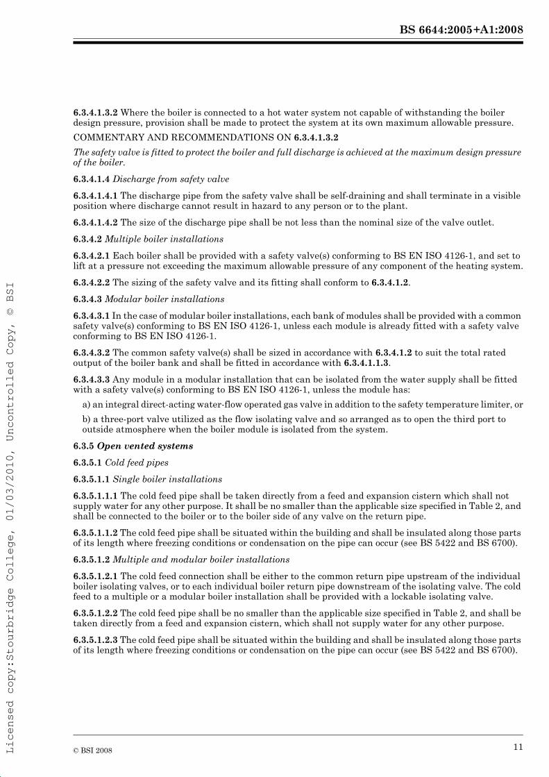
Table 2 — Cold feed pipe sizes
6.3.5.2 Open vent pipes
6.3.5.2.1 General
6.3.5.2.1.1 Open vent pipes shall not be fitted with isolating valves, except as specified in 6.3.5.2.2.5. There shall be no obstructions which could prevent safe venting of the boiler during operation or isolation.
6.3.5.2.2 Single boiler installations
6.3.5.2.2.1 Single boiler installations shall be fitted with an open vent pipe which rises continuously by the shortest practicable route to the venting point.
COMMENTARY AND RECOMMENDATIONS ON 6.3.5.2.2.1
In some cases where the flow pipe connection is situated in a position at the top of the boiler that permits satisfactory venting, the boiler need not be provided with a vent pipe tapping. In these circumstances the flow pipe may be utilized as part of the open vent pipe.
6.3.5.2.2.2 Each vent pipe shall be sized according to the maximum rated output of the boiler it is intended to protect, and shall be not less than the minimum size specified in Table 3.
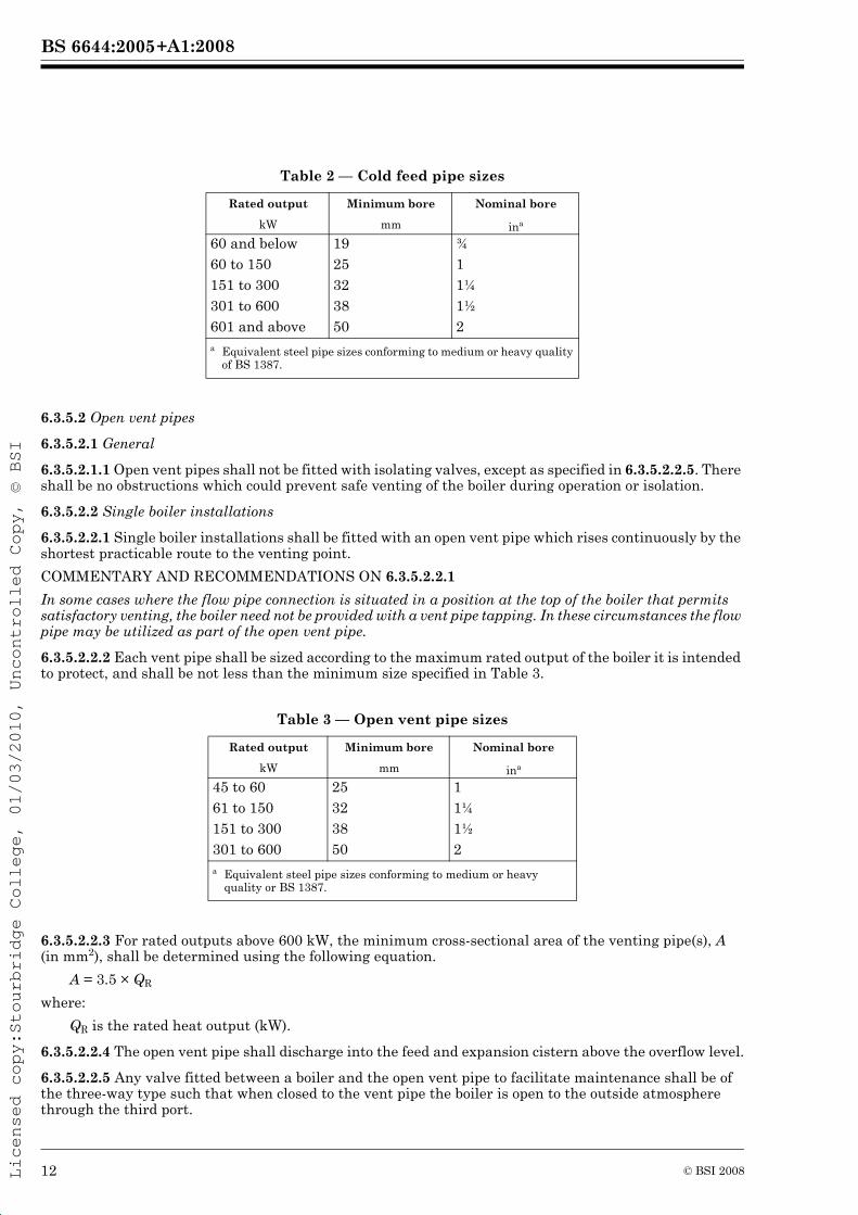
Table 3 — Open vent pipe sizes
6.3.5.2.2.3 For rated outputs above 600 kW, the minimum cross-sectional area of the venting pipe(s), A (in mm2), shall be determined using the following equation.
A = 3.5 × QR
where:
QR is the rated heat output (kW).
6.3.5.2.2.4 The open vent pipe shall discharge into the feed and expansion cistern above the overflow level.
6.3.5.2.2.5 Any valve fitted between a boiler and the open vent pipe to facilitate maintenance shall be of the three-way type such that when closed to the vent pipe the boiler is open to the outside atmosphere through the third port.
Rated output Minimum bore Nominal bore
kW mm ina
60 and below 19 ¾60 to 150 25 1151 to 300 32 1¼301 to 600 38 1½601 and above 50 2a Equivalent steel pipe sizes conforming to medium or heavy quality
of BS 1387.
Rated output Minimum bore Nominal bore
kW mm ina
45 to 60 25 161 to 150 32 1¼ 151 to 300 38 1½ 301 to 600 50 2a Equivalent steel pipe sizes conforming to medium or heavy
quality or BS 1387.
12 © BSI 2008
+A1:2008BS 6644:2005
Licensed copy:Stourbridge College, 01/03/2010, Uncontrolled Copy, © BSI
The valve shall incorporate means of indicating the position of the open port and shall have a nominal bore not less than that of the vent pipe in which it is fitted.
6.3.5.2.2.6 Open vent pipes shall be insulated along those parts of their lengths where freezing conditions can occur (see BS 5422 and BS 6700).
COMMENTARY AND RECOMMENDATIONS ON 6.3.5.2.2.6
As far as practicable, open vent pipes should be situated inside buildings as an aid to reducing freezing problems.
6.3.5.2.3 Multiple boiler installations
6.3.5.2.3.1 Multiple boiler installations shall be vented by one of the following means:
a) a common vent pipe; or
b) individual open vent pipes arising continuously by the shortest practicable route to the venting point; or
c) individual vent pipes connected to a common vent pipe, the cross-sectional area of which is equal to the total cross-sectional area of the individual pipes.
6.3.5.2.3.2 Each vent pipe shall be sized according to the maximum rated output of the boiler it is intended to protect, and shall be not less than the minimum size specified in Table 3 or obtained from the equation in 6.3.5.2.2.3, as appropriate.
Any common vent pipe shall be sized according to the total rated heat output of the installation.
6.3.5.2.3.3 Vent pipes and associated fittings shall additionally conform to 6.3.5.2.2.4, 6.3.5.2.2.5 and 6.3.5.2.2.6.
6.3.5.2.4 Modular boiler installations
6.3.5.2.4.1 Each bank of modules in a modular boiler installation shall be fitted with an open vent pipe on the common flow pipe.
6.3.5.2.4.2 The vent pipe shall be sized to suit the total capacity of the boiler bank in accordance with 6.3.5.2.2.2 or 6.3.5.2.2.3, as appropriate.
6.3.5.2.4.3 The vent pipe shall be connected between the boiler bank and the safety valve.
6.3.5.2.4.4 Any individual module in a modular boiler installation that is fitted with a water isolating valve shall be provided with:
a) an open vent pipe sized in accordance with 6.3.5.2.2.2 or 6.3.5.2.2.3, as appropriate, and fitted in accordance with 6.3.5.2.2.4, 6.3.5.2.2.5 and 6.3.5.2.2.6, as appropriate, or
b) an open vent pipe connecting to a common open vent, but capable of isolation to outside atmosphere via a 3-port valve, or
c) a 3-port valve utilized as the flow isolating valve and so arranged as to open the third port to outside atmosphere when the boiler module is isolated from the system.
COMMENTARY AND RECOMMENDATIONS ON 6.3.5.2.4.4
A boiler fitted with an integral gas valve directly operated by water flow does not require an open vent pipe.
6.3.6 Sealed systemsNOTE For gas cushion systems, which are not covered by this standard, reference should be made to BS 6880-2.
6.3.6.1 Expansion vessel
6.3.6.1.1 Any diaphragm expansion vessel incorporated in a sealed system shall conform to BS 4814.
6.3.6.1.2 The expansion vessel shall be installed in accordance with the manufacturer’s instructions.
13© BSI 2008
+A1:2008BS 6644:2005
Licensed copy:Stourbridge College, 01/03/2010, Uncontrolled Copy, © BSI
6.3.6.1.3 The expansion vessel shall have an acceptance volume sufficient to accommodate the volume change of the system water over the range of temperatures between 0 °C and the boiler’s maximum allowable temperature.NOTE The diaphragms in expansion vessels are generally limited to an operating temperature of 100 °C to 110 °C. Where higher temperatures are to be used it might be necessary to make other provisions. Reference to the manufacturer’s instructions should be made.
6.3.6.1.4 The connecting pipe between the expansion vessel and the hot water system shall not incorporate any valve or other device that could prevent safe operation of the expansion vessel.NOTE Where considered necessary, an isolating valve may be fitted, provided that it is capable of being locked in the open position.
6.3.6.2 Provision for filling and make-up of the boiler
6.3.6.2.1 A sealed system shall be provided with a means for initial filling which is acceptable to the local water supplier.
6.3.6.2.2 Provision shall be made for replacing water lost from the hot water system by means of any of the following.
a) A self-contained automatic unit comprising a cistern fitted with a float operated valve conforming to BS 1212-1, BS 1212-2 or BS 1212-3, as applicable, and installed to have a Family A, type A or B air gap at the inlet in accordance with BS EN 13076 or BS EN 13077, as applicable.
The outlet from the cistern shall feed a pressure booster that is fitted with a check valve conforming to BS 6282-1, a pressure-reducing valve conforming to BS EN 1567, and a pressure switch.NOTE 1 The unit might also require an expansion vessel and pressure gauge.
NOTE 2 Family E, type A, B, C and D check valves are the subject of draft European Standard prEN 13959.
b) A separate primary feed cistern, used for no other purpose, from which water is taken by gravity only, provided the cistern is fitted with a float operated valve conforming to BS 1212-1, BS 1212-2 or BS 1212-3, as applicable, at the inlet and installed in the cistern to provide a Family A, type F air gap.NOTE 3 The connection to the primary cistern can be direct from mains water supply or from a cold water distribution pipe.
NOTE 4 Family A, type F air gaps are the subject of a draft European Standard, prEN 14622.
c) A verifiable backflow prevention device offering fluid category 4 protection, such as an RPZ (Reduced Pressure Zone) valve or some other no less effective device.
COMMENTARY AND RECOMMENDATIONS ON 6.3.6.2.2
The measures specified satisfy fluid category 4 requirements for backflow protection as detailed in the Water Supply (Water Fittings) Regulations 1999 [9].
6.3.6.2.3 The static head or boosted supply pressure shall be such as to provide at least the required system operating pressure.
6.3.6.2.4 The cold feed shall incorporate a non-return valve, and an isolating valve capable of being locked in the open position during normal operation.
6.3.6.2.5 An automatic air venting device shall be fitted between the isolating valve and the non-return valve such that the isolating valve is between the air venting device and the system pipework.
6.3.6.3 Controls
6.3.6.3.1 A low water pressure cut-off device shall be fitted to protect the hot water system against loss of water pressure due to leakage.
The cut-off device shall be wired in series with the boiler controls and shall operate to give safety shut-down and lockout.
The set pressure of the cut-off device shall be such as to ensure that boiling does not occur in any part of the system while the working temperature is maintained.
6.3.6.3.2 Where a high water pressure cut-off device is fitted, this shall be wired in series with the boiler controls and shall operate to give safety shut-down and lockout.
14 © BSI 2008
+A1:2008BS 6644:2005
Licensed copy:Stourbridge College, 01/03/2010, Uncontrolled Copy, © BSI
6.3.6.4 Additional installation components
6.3.6.4.1 Water pressure gauge
The boiler system shall be fitted with a gauge that indicates the water pressure in metres of water or bars. The gauge shall be fitted either on the boiler or on the adjacent flow pipe, and shall be sited such that it can be easily read and replaced without draining the boiler/system.
6.3.6.4.2 Temperature gauge
A temperature gauge shall be fitted to indicate the temperature in degrees Celsius of the boiler flow water. It shall be sited and fitted in such a way that it can be easily read and replaced without draining the boiler.
6.3.6.4.3 Drain valve
A drain valve shall be positioned to allow the boiler to be drained. This shall be fitted with a removable key (see also 6.1.8).
COMMENTARY AND RECOMMENDATIONS ON 6.3.6.4.3
The size of the valve should be selected having regard to the water content of the boiler. It should either be located directly over a drain or have the facility for connecting a hose. Draining should take no more than 30 min.
6.4 Condensation in boilers
6.4.1 Non-condensing boilers
Where condensation is likely to occur in the boiler and the volume of condensate produced is liable to be a nuisance or detrimental in any way to the boiler, provision shall be made either for its collection and disposal, or for it to be minimized by raising the boiler return water temperature as rapidly as possible above the water dew-point temperature of the combustion products. The boiler manufacturer’s recommendations shall be followed.
COMMENTARY AND RECOMMENDATIONS ON 6.4.1
Condensation can be minimized by using a thermostatically controlled bypass designed to divert a proportion of the boiler flow water directly to the return connection whenever the temperature of the system water returning to the boiler is below the dew-point temperature.
6.4.2 Condensing boilers
Condensing boilers shall be provided with a safe and effective means for the disposal of condensate.
COMMENTARY AND RECOMMENDATIONS ON 6.4.2
Reference may be made to the manufacturer’s instructions and IGE/UP/10 [15].
6.5 Gas supplies and pipework
6.5.1 General
6.5.1.1 The withdrawal, opening or removal of boiler parts for routine maintenance shall not be restricted by the gas supply and other pipework (see also 6.6.1).
COMMENTARY AND RECOMMENDATIONS ON 6.5.1.1
The manufacturer’s instructions should be consulted to determine those boiler parts which require to be withdrawn, opened or removed for maintenance purposes.
6.5.1.2 Means for the complete isolation of the gas supply of individual boilers shall be provided in an accessible position.
Unless this is already an integral part of the boiler, the means of isolation shall be a fast-acting manual isolation valve, e.g. a 90º operation valve, adjacent to each boiler.
COMMENTARY AND RECOMMENDATIONS ON 6.5.1.2
A means of isolating the gas supply might be supplied with the boiler.
6.5.1.3 A manual valve for boiler room isolation shall be fitted in the gas supply. The manual valve for isolating the boiler house shall be clearly identifiable and readily accessible for operation.
15© BSI 2008
+A1:2008BS 6644:2005
Licensed copy:Stourbridge College, 01/03/2010, Uncontrolled Copy, © BSI
6.5.2 2nd family gases
6.5.2.1 The installer shall ensure that the gas pressure in a new or existing service pipe is controlled so as to supply gas at a pressure suitable for the boiler(s).
COMMENTARY AND RECOMMENDATIONS ON 6.5.2.1
Where a boiler is supplied without a governor fitted, a governor conforming to BS EN 88 or BS 6448, as appropriate, should be fitted.
6.5.2.2 Where there is an existing primary gas meter, the appropriate gas supplier or gas transporter shall be consulted to ensure that the service and meter supply capacity is adequate for any proposed new boiler in addition to any existing gas-fired appliances.
6.5.2.3 Installation pipework shall be sized and installed in accordance with IGE/UP/2 [22].
COMMENTARY AND RECOMMENDATIONS ON 6.5.2.2 AND 6.5.2.3
For large single and multiple boiler installations, consideration should be given to the installation of check gas meters to assist in the monitoring of boiler performance. Due consideration should be given to the additional pressure drop across check meters.
6.5.2.4 The installation of any booster shall be in accordance with IGE/UP/2 [22].
6.5.2.5 The inlet and outlet connection of any gas booster shall be fitted with stainless steel flexible pipes conforming to BS EN ISO 10380:2003, Type 1.
COMMENTARY AND RECOMMENDATIONS ON 6.5.2.5
Flexible hoses conforming to BS EN ISO 10380:2003, Type 1, only have a 10 000 cycle fatigue life. Consideration should be given to fitting flexible pipes with a higher life of, for example, 30 000 cycles, as highlighted in BS 6501:2004, A.2.4.
6.5.2.6 The cut-off pressure shall be agreed with the gas transporter or gas conveyor.
COMMENTARY AND RECOMMENDATIONS ON 6.5.2.6
Attention is drawn to the Gas Safety (Installation and Use) Regulations 1998 [1], Regulation 38, which requires fourteen days notice to the gas transporter of the intention to fit a gas booster.
6.5.3 3rd family gases (LPG)
6.5.3.1 Where a boiler is supplied with third family gas the installer shall ensure that the gas pressure is controlled so as to supply gas at a pressure suitable for the boiler.
COMMENTARY AND RECOMMENDATIONS ON 6.5.3.1
Where a boiler is supplied without a governor fitted, it is recommended that a governor conforming to BS EN 88 or BS 6448, as appropriate, be fitted.
6.5.3.2 LPG storage cylinders shall where practicable be located outside the building. If this is not practicable, the total quantity of LPG in the building shall be in accordance with LPGA CP 24, Part 6 [23].
6.5.3.3 Cylinders of LPG not in use shall be stored outside the building, unless this is not practicable (see LPGA CP 7 [24]).
COMMENTARY AND RECOMMENDATIONS ON 6.5.3.3
LPGA CP 7 [24] covers the storage of LPG cylinders on indoors and outdoors.
LPGA CPs 24.1 [25] and 24.6 [23] give guidance on safe practice.
6.5.3.4 The third family gas pipework system shall be in accordance with the LP Gas Association Code of Practice No. 22: LPG Piping, System Design and Installation [26] or IGE/UP/2 [22], as appropriate.
6.6 Electrical installation
6.6.1 The electrical wiring shall be such that it does not restrict the withdrawal, opening or removal of boiler parts for routine maintenance (see also 6.5.1.1).
16 © BSI 2008
+A1:2008BS 6644:2005
Licensed copy:Stourbridge College, 01/03/2010, Uncontrolled Copy, © BSI
COMMENTARY AND RECOMMENDATIONS ON 6.6.1
The manufacturer’s instructions should be consulted to determine those parts which require to be withdrawn, opened or removed for maintenance purposes.
6.6.2 All external wiring shall be carried out and checked in accordance with BS 7671.
6.6.3 Electrical components shall be checked to ensure that they are suitable for the voltage range and frequency available.
COMMENTARY AND RECOMMENDATIONS ON 6.6.3
The manufacturer’s instructions can include detailed instructions for the electrical installation, together with a comprehensive test procedure for proving the completed installation. Where such instructions are provided they should be observed by the installer.
6.6.4 Where existing fixed electrical installations are used, these shall be inspected and tested in accordance with the requirements of BS 7671. The ability of the existing electrical system to carry the additional electrical loading shall be assessed at this time.
6.6.5 The electrical supply to the boiler(s) shall be protected against excess current.
6.6.6 Means for the complete electrical isolation of individual boilers shall be provided in an accessible position adjacent to each boiler.
6.6.7 In multiple boiler installations, care shall be taken to ensure that the isolation of any individual boiler does not interfere with the correct and safe operation of the remaining boilers.
6.6.8 All electrical enclosures, components and cabling shall be suitable for the environment, in particular with regard to any hazardous area classification (see DSEAR [14] and their supporting ACOPs, HS(L)134 [27], HS(L)135 [28], HS(L)136 [29], HS(L)137 [30] and HS(L)138 [31], and INDG 370 [32]), temperature and dust effects. In addition:
a) all electrical components, cables, etc. shall be suitable for the electrical supply available;
b) all electrical components with voltage range selectors shall be adjusted to the value of voltage available at the supply;
c) all electrical components shall be connected in accordance with the manufacturer’s instructions;
d) any electrical component requiring removal for periodic servicing shall be provided with ready means of disconnection, such as plugs and sockets, and shall be sited so as to be readily accessible;
e) all earth and electrical bonding conductors shall be of copper and of sufficient cross-sectional area and the insulation provided on any earth or bonding conductors shall have the colour combination yellow and green; and
f) all overload earth fault and excess current protection shall be appropriately rated.
6.7 Boiler controls
Appropriate boiler controls shall be installed to ensure conservation of fuel and power.
COMMENTARY AND RECOMMENDATIONS ON 6.7
In addition to factors affecting safety and convenience, it is important to consider energy conservation and the requirements of the Building Regulations [5, 6 and 7]. A wide variety of automatic controls and control systems, designed to minimize wastage of fuel, is available. These range from simple time controls to complete building energy management systems. Where necessary, advice on the selection and use of such systems should be sought from appropriate specialists in this field.
6.8 Additional safety controls
6.8.1 Any safety controls, other than those integral to the boiler, the function of which is to deal automatically with an abnormal or potentially dangerous condition, shall:
a) shut off the gas supply and require manual resetting; and
b) operate a warning light and/or other signal drawing attention to the condition.
Any warning indicator shall remain in operation until the condition leading to shut-down has been rectified and the control reset.
17© BSI 2008
+A1:2008BS 6644:2005
Licensed copy:Stourbridge College, 01/03/2010, Uncontrolled Copy, © BSI
6.8.2 Safety controls shall be provided to protect boiler installations at or near roof level against the severe conditions likely at such sites.
6.9 Air supply and ventilation
6.9.1 General
6.9.1.1 There shall be provision for a supply of air for combustion, for combustion products dilution, where relevant, and for ventilation in accordance with the requirements of 6.9.2, 6.9.3 or 6.9.4, as applicable.
6.9.1.2 The air supplied for boiler room ventilation shall be such that the maximum temperatures within the boiler house shall be:
— 25 °C at floor level (or 100 mm above floor level);— 32 °C at mid-level (1.5 m above floor level); and— 40 °C at ceiling level (or 100 mm below ceiling level).
COMMENTARY AND RECOMMENDATIONS ON 6.9.1.2
Where the plant is likely to be used at or near maximum capacity during the summer months, additional ventilation might be required.
6.9.1.3 The provision of combustion and ventilation air shall be achieved by one of the following four methods, as appropriate.
a) Air shall be supplied via one or more low-level openings and discharged via one or more high-level openings, the motive force being provided by thermal effects.
b) Air shall be supplied by a fan via one or more low-level openings, and discharged naturally via one or more high-level openings.
c) Air shall be supplied by a fan via one or more low-level openings and discharged by means of a second fan at a high-level opening. The fans shall be selected and controlled so as not to cause a negative pressure (relative to the outside atmosphere) developing in the boiler room.
d) In the case of balanced compartment installation, air shall be supplied and discharged by means of a purpose-designed (or proprietary) flueing/ventilation system based solely on high-level permanent openings situated immediately adjacent to the flue outlet.
COMMENTARY AND RECOMMENDATIONS ON 6.9.1.3
The apertures of an air opening should allow entry of a 5 mm diameter ball. No gauze or flyscreen (i.e. mesh having apertures of less than 5 mm) should be incorporated or subsequently fitted to an air vent. Such practices might compromise the free-area.
For a balanced compartment installation, specialist advice should be sought from the system manufacturer (see also 6.9.4).
6.9.1.4 All air inlet and extract fans shall be fitted with automatic controls causing at least safety shut-down of the boiler(s) in the event of the inlet or extract air failing.
6.9.2 Room-sealed (Type C) boilers
6.9.2.1 Installation in a boiler room
The ventilation provided shall be adequate to ensure that the boiler room temperature meets the requirements of 6.9.1.2, and shall not be less than 2 cm2 free-area per kW of net heat input at high and at low level.
COMMENTARY AND RECOMMENDATIONS ON 6.9.2.1
Annex A gives the methodology for arriving at the ventilation specified in this requirement. In the case of room-sealed boilers where combustion air is ducted to the appliance from outside and the combustion products ducted to the outside air, no additional provisions for the supply of combustion air or for combustion products dilution are necessary. Where a boiler is to operate in summer months, e.g. domestic hot water heating, the above allowance should be sufficient, provided that it does not operate for more than 50 per cent of the time. If the boiler is to operate at a higher percentage of the time, increased ventilation will be required, e.g. at 75 per cent, 3 cm2 will be required and at 100 per cent, 4 cm2 free-area per kW will be required at high and at low level.
18 © BSI 2008
+A1:2008BS 6644:2005
Licensed copy:Stourbridge College, 01/03/2010, Uncontrolled Copy, © BSI
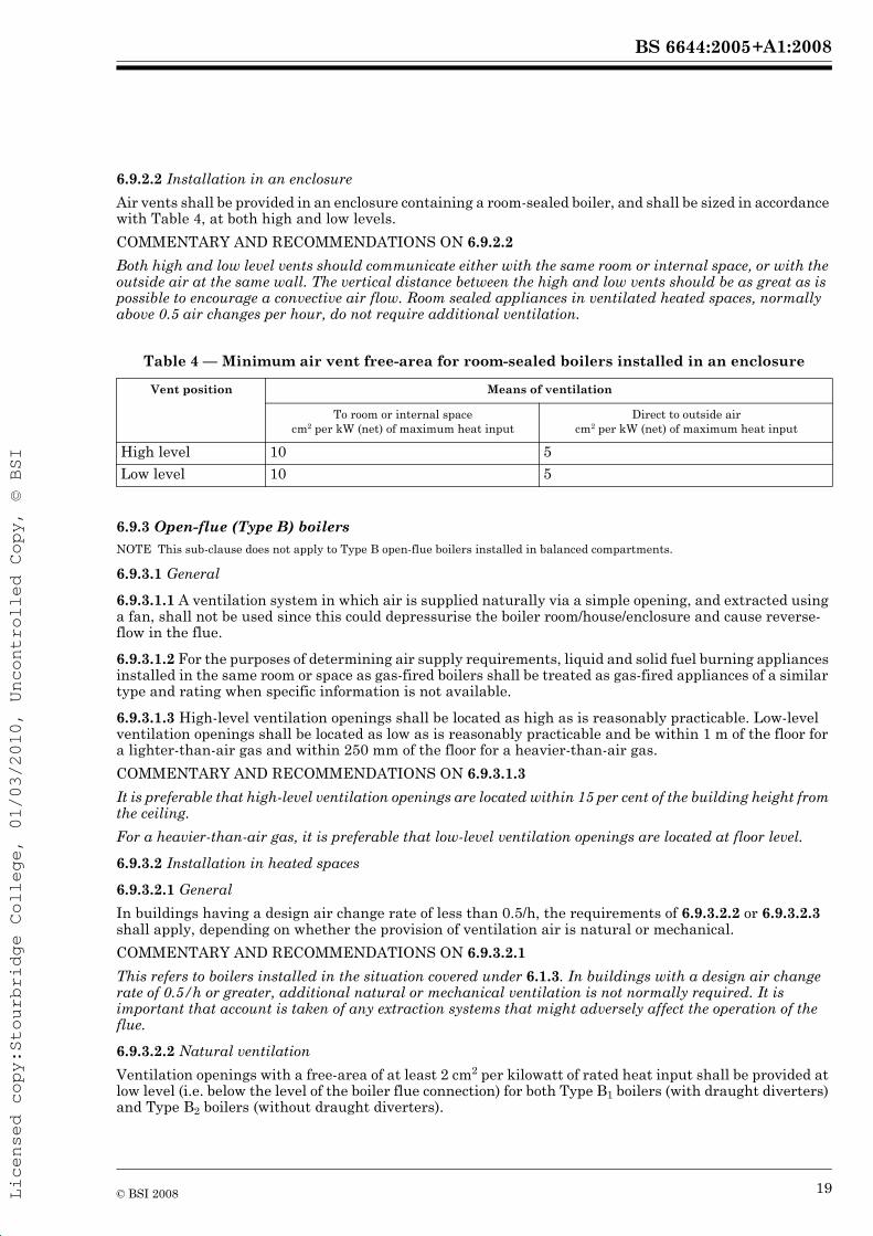
6.9.2.2 Installation in an enclosure
Air vents shall be provided in an enclosure containing a room-sealed boiler, and shall be sized in accordance with Table 4, at both high and low levels.
COMMENTARY AND RECOMMENDATIONS ON 6.9.2.2
Both high and low level vents should communicate either with the same room or internal space, or with the outside air at the same wall. The vertical distance between the high and low vents should be as great as is possible to encourage a convective air flow. Room sealed appliances in ventilated heated spaces, normally above 0.5 air changes per hour, do not require additional ventilation.
Table 4 — Minimum air vent free-area for room-sealed boilers installed in an enclosure
6.9.3 Open-flue (Type B) boilersNOTE This sub-clause does not apply to Type B open-flue boilers installed in balanced compartments.
6.9.3.1 General
6.9.3.1.1 A ventilation system in which air is supplied naturally via a simple opening, and extracted using a fan, shall not be used since this could depressurise the boiler room/house/enclosure and cause reverse-flow in the flue.
6.9.3.1.2 For the purposes of determining air supply requirements, liquid and solid fuel burning appliances installed in the same room or space as gas-fired boilers shall be treated as gas-fired appliances of a similar type and rating when specific information is not available.
6.9.3.1.3 High-level ventilation openings shall be located as high as is reasonably practicable. Low-level ventilation openings shall be located as low as is reasonably practicable and be within 1 m of the floor for a lighter-than-air gas and within 250 mm of the floor for a heavier-than-air gas.
COMMENTARY AND RECOMMENDATIONS ON 6.9.3.1.3
It is preferable that high-level ventilation openings are located within 15 per cent of the building height from the ceiling.
For a heavier-than-air gas, it is preferable that low-level ventilation openings are located at floor level.
6.9.3.2 Installation in heated spaces
6.9.3.2.1 General
In buildings having a design air change rate of less than 0.5/h, the requirements of 6.9.3.2.2 or 6.9.3.2.3 shall apply, depending on whether the provision of ventilation air is natural or mechanical.
COMMENTARY AND RECOMMENDATIONS ON 6.9.3.2.1
This refers to boilers installed in the situation covered under 6.1.3. In buildings with a design air change rate of 0.5/h or greater, additional natural or mechanical ventilation is not normally required. It is important that account is taken of any extraction systems that might adversely affect the operation of the flue.
6.9.3.2.2 Natural ventilation
Ventilation openings with a free-area of at least 2 cm2 per kilowatt of rated heat input shall be provided at low level (i.e. below the level of the boiler flue connection) for both Type B1 boilers (with draught diverters) and Type B2 boilers (without draught diverters).
Vent position Means of ventilation
To room or internal spacecm2 per kW (net) of maximum heat input
Direct to outside aircm2 per kW (net) of maximum heat input
High level 10 5
Low level 10 5
19© BSI 2008

+A1:2008BS 6644:2005
Licensed copy:Stourbridge College, 01/03/2010, Uncontrolled Copy, © BSI
6.9.3.2.3 Mechanical ventilation
Sufficient ventilation air shall be provided, in accordance with the requirements of 6.9.1.3 and 6.9.1.4 to ensure that the building air change rate is at least 0.5/h.
6.9.3.3 Installation in boiler rooms or enclosures
6.9.3.3.1 Natural ventilation
6.9.3.3.1.1 Where a natural ventilation system is used, there shall be provision for either:
a) permanent low- and high-level ventilation openings communicating directly with the outside air; or
b) in the case of a balanced compartment installation, a purpose-designed (proprietary) flueing and ventilation system based solely on high-level permanent openings situated immediately adjacent to the flue outlet and installed in accordance with 6.9.4.
COMMENTARY AND RECOMMENDATIONS ON 6.9.3.3.1.1b)
Where a purpose-designed (proprietary) flueing and ventilation system based solely on high-level permanent openings is used, specialist advice from the flueing and ventilation system manufacturer should be sought.
6.9.3.3.1.2 The ventilation openings shall be fitted with grilles of negligible resistance to airflow and shall be sited so that they cannot be easily blocked or flooded.
6.9.3.3.1.3 Where both low- and high-level openings are used, the grilles shall have a total minimum free-area as follows:
a) for boiler rooms
1) low level (inlet): 4 cm2 per kilowatt of total rated net heat input;
2) high level (outlet): 2 cm2 per kilowatt of total rated net heat input.
b) for enclosures
1) low level (inlet): 10 cm2 per kilowatt of total rated net heat input;
2) high level (outlet): 5 cm2 per kilowatt of total rated net heat input.
6.9.3.3.1.4 For an exposed, i.e. free-standing, boiler house where low- and high-level ventilation openings are provided, the openings shall be on at least two sides of the boiler house.
COMMENTARY AND RECOMMENDATIONS ON 6.9.3.3.1.4
Ventilation grilles should be of a type which minimizes high velocity air-streams. Whilst ventilation openings on two sides of a free-standing boiler house are normally sufficient, for sites subject to severe exposure it is recommended that ventilation openings be placed on all four sides where practicable. Inlet and outlet openings should be on the same wall. Where a boiler installation is to operate in summer months, e.g. domestic hot water heating, the above allowance should be sufficient, provided that it does not operate for more than 50 per cent of the time. If the boiler installation is to operate at a higher percentage of the time, increased ventilation will be required, e.g. at 75 per cent, an additional 1 cm2 and at 100 per cent, an additional 2 cm2 of free-area per kW will be required at high and at low level.
6.9.3.3.1.5 For natural draught boilers installed in basement, underground or similarly sited boiler houses where:
a) communication with the outside air is possible only by means of high-level ventilation openings; and
b) it is not intended or possible to use a purpose designed ventilation system as described in 6.9.1.3d),
the inlet air shall be conducted to low level by ducting of a cross-sectional area not less than the total free-area of this inlet air opening. High- and low-level ventilation shall not be provided by means of a single duct.
COMMENTARY AND RECOMMENDATIONS ON 6.9.3.3.1.5
For forced and induced draught boilers in similar situations, it is recommended that the inlet air is also ducted to low level.
Boilers fired by 3rd family gases are not permitted to be installed in basements. See 6.1.10.
Low level ventilation should be fitted to connected spaces below locations of boilers fired by 3rd family gases.
20 © BSI 2008
+A1:2008BS 6644:2005
Licensed copy:Stourbridge College, 01/03/2010, Uncontrolled Copy, © BSI
6.9.3.3.2 Mechanical ventilation
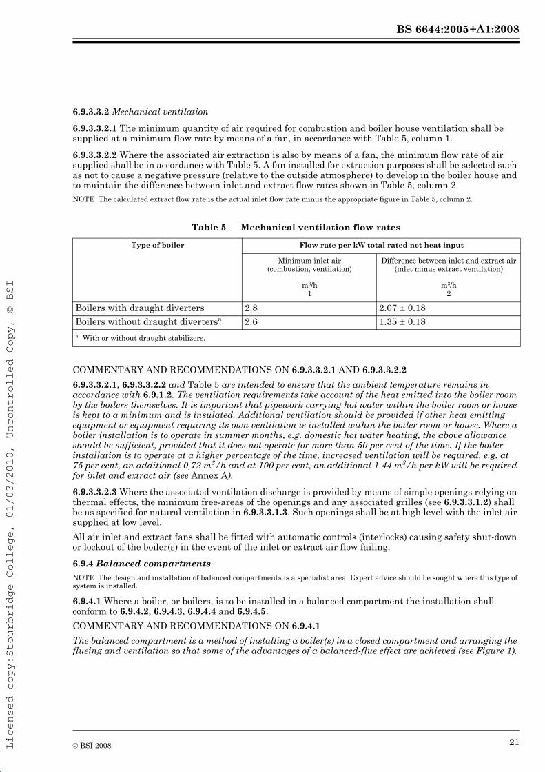
6.9.3.3.2.1 The minimum quantity of air required for combustion and boiler house ventilation shall be supplied at a minimum flow rate by means of a fan, in accordance with Table 5, column 1.
6.9.3.3.2.2 Where the associated air extraction is also by means of a fan, the minimum flow rate of air supplied shall be in accordance with Table 5. A fan installed for extraction purposes shall be selected such as not to cause a negative pressure (relative to the outside atmosphere) to develop in the boiler house and to maintain the difference between inlet and extract flow rates shown in Table 5, column 2.NOTE The calculated extract flow rate is the actual inlet flow rate minus the appropriate figure in Table 5, column 2.
Table 5 — Mechanical ventilation flow rates
COMMENTARY AND RECOMMENDATIONS ON 6.9.3.3.2.1 AND 6.9.3.3.2.2
6.9.3.3.2.1, 6.9.3.3.2.2 and Table 5 are intended to ensure that the ambient temperature remains in accordance with 6.9.1.2. The ventilation requirements take account of the heat emitted into the boiler room by the boilers themselves. It is important that pipework carrying hot water within the boiler room or house is kept to a minimum and is insulated. Additional ventilation should be provided if other heat emitting equipment or equipment requiring its own ventilation is installed within the boiler room or house. Where a boiler installation is to operate in summer months, e.g. domestic hot water heating, the above allowance should be sufficient, provided that it does not operate for more than 50 per cent of the time. If the boiler installation is to operate at a higher percentage of the time, increased ventilation will be required, e.g. at 75 per cent, an additional 0,72 m3/h and at 100 per cent, an additional 1.44 m3/h per kW will be required for inlet and extract air (see Annex A).
6.9.3.3.2.3 Where the associated ventilation discharge is provided by means of simple openings relying on thermal effects, the minimum free-areas of the openings and any associated grilles (see 6.9.3.3.1.2) shall be as specified for natural ventilation in 6.9.3.3.1.3. Such openings shall be at high level with the inlet air supplied at low level.
All air inlet and extract fans shall be fitted with automatic controls (interlocks) causing safety shut-down or lockout of the boiler(s) in the event of the inlet or extract air flow failing.
6.9.4 Balanced compartmentsNOTE The design and installation of balanced compartments is a specialist area. Expert advice should be sought where this type of system is installed.
6.9.4.1 Where a boiler, or boilers, is to be installed in a balanced compartment the installation shall conform to 6.9.4.2, 6.9.4.3, 6.9.4.4 and 6.9.4.5.
COMMENTARY AND RECOMMENDATIONS ON 6.9.4.1
The balanced compartment is a method of installing a boiler(s) in a closed compartment and arranging the flueing and ventilation so that some of the advantages of a balanced-flue effect are achieved (see Figure 1).
Type of boiler Flow rate per kW total rated net heat input
Minimum inlet air(combustion, ventilation)
Difference between inlet and extract air(inlet minus extract ventilation)
m3/h1
m3/h2
Boilers with draught diverters 2.8 2.07 ú 0.18
Boilers without draught divertersa 2.6 1.35 ú 0.18a With or without draught stabilizers.
21© BSI 2008
+A1:2008BS 6644:2005
Licensed copy:Stourbridge College, 01/03/2010, Uncontrolled Copy, © BSI
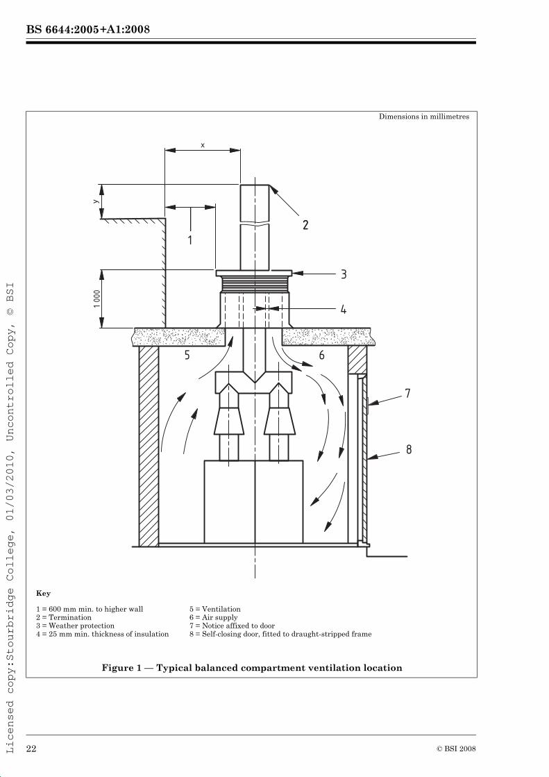
Dimensions in millimetres
Key
1 = 600 mm min. to higher wall 2 = Termination 3 = Weather protection 4 = 25 mm min. thickness of insulation
5 = Ventilation 6 = Air supply 7 = Notice affixed to door 8 = Self-closing door, fitted to draught-stripped frame
Figure 1 — Typical balanced compartment ventilation location
2
1 00
0
12
7
8
y
x
3
4
5 6
22 © BSI 2008
+A1:2008BS 6644:2005
Licensed copy:Stourbridge College, 01/03/2010, Uncontrolled Copy, © BSI
6.9.4.2 The design of flueing and ventilation for balanced compartments shall be such as to ensure safe and effective operation of the boiler, e.g. combustion performance, in accordance with the boiler manufacturer’s instructions, and shall ensure that temperatures within the compartment are in accordance with 6.9.4.3. (See also 6.10.)
A balanced compartment shall have a self-closing flush door(s) fitting tightly to the frame and shall incorporate a draught sealing strip. A notice shall be attached to the door(s) stating that the door(s) have to be kept closed.
Where an internal compartment is used as a boiler house and the compartment door(s) opens to a habitable area, the door(s) shall be fitted with a switch to shut down the boiler when the door(s) is opened.
There shall be no other ventilation openings, e.g. openable windows, into the compartment, except that in the case of 3rd family gas installations an opening of at least 60 cm2 shall be provided at floor level communicating directly to the outside air.
COMMENTARY AND RECOMMENDATIONS ON 6.9.4.2
In the case of larger boiler houses where other ancillary equipment is involved and regular access to the boiler house might be required, a time delay of up to 30 s may be incorporated in the switch. In the case of 3rd family gas installations, the installation of a gas leak detector conforming to BS EN 61779-4 or BS EN 61779-5 should be considered in order to give warning of any possible leakage (see 6.8).
6.9.4.3 Temperatures within a balanced compartment shall conform to 6.9.1.2. Any exposed length of flue within the compartment and any exposed hot water pipe-work or air ducts shall be insulated to minimize heat transfer to the compartment
6.9.4.4 To allow for both combustion and ventilation air, the total area of high-level ventilation openings to a balanced compartment installation shall not be less than 10 cm2/kW for installations up to 500 kW total
2
The air intakes shall be so positioned and protected as to prevent the ingress of rain, leaves and debris, and shall be positioned at least 600 mm from any obstruction to allow a free flow of air under all wind conditions.
6.9.4.5 Where the flue termination is within 2 500 mm (dimension x in Figure 1) of a nearby structure, the termination shall be taken at least 1 000 mm (dimension y in Figure 1) above the level of that structure.
COMMENTARY AND RECOMMENDATIONS ON 6.9.4.5
In all cases, flue termination positions have to provide correct dilution of the combustion products in order to meet the requirements of the Clean Air Act [12].
6.10 Flues
6.10.1 GeneralNOTE This clause highlights some of the main design considerations. The requirements in this clause are not exhaustive and reference should be made to IGE/UP/10 [15].
6.10.1.1 Construction
Any new flue selected for installation shall be of asbestos-free, robust, durable and corrosion-resistant materials of such nature, quality and thickness as to not be unduly affected by heat, condensation and the products of combustion, and which conform to BS 5854 and BS EN 1856-1 and BS EN 1856-2, or BS 4076, as appropriate. It shall be placed, shielded, constructed and supported so that when used normally, it:
a) prevents ignition of any part of the building;
b) prevents any products of combustion from entering the building; and
c) ensures that there is neither undue risk of accidental damage to the flue nor undue hazard to persons in or about the building.
COMMENTARY AND RECOMMENDATIONS ON 6.10.1.1
The Asbestos (Prohibition) Regulations 1992, as amended [13] place restrictions on the use of asbestos material, including a total ban of asbestos cement and its product. New (or alterations to existing) flue systems should not be constructed from materials containing asbestos. Existing flue systems may be reused
! "! " net heat input. For installations above 500 kW total net heat input, the high level openings shall be at least 8cm /kW for the additional net heat input over 500 kW.
23© BSI 2008
+A1:2008BS 6644:2005
Licensed copy:Stourbridge College, 01/03/2010, Uncontrolled Copy, © BSI
in situ as flue systems provided that they are mechanically sound and conform to the requirements of this British Standard.
6.10.1.2 Non-metallic flue materials shall not be used unless permitted in the boiler manufacturer’s instructions.
6.10.1.3 Condensation in fluesWhere condensation might occur other than during the first start-up of the burner, the flue system used shall be so designed and constructed as to ensure the total disposal of water condensate to a drain.
6.10.1.4 Non-condensing boilersIf condensation within the flue is conceivable at times other than during the first start up of the burner, an insulated flue, e.g. double-walled flue, shall be used. In addition or as an alternative to this, flue components conforming to 6.10.1.5 shall be used.
COMMENTARY AND RECOMMENDATIONS ON 6.10.1.4
If condensation within the flue is acceptable, the flue layout should be such that the condensate can flow freely to a point at which it can be released safely, preferably to a drain.
The use of double-walled or otherwise insulated flues should be used for exposed flues.
6.10.1.5 Condensing boilersThe flue components, including liners, used shall be impervious to condensates and shall be resistant to corrosion. Provisions shall be made for draining and disposal of the condensate (see 5.2). Any condensate drain pipe(s) from the flue to the disposal point shall be resistant to corrosion [see item c) of the Commentary and Recommendations on 5.2]. These shall have an internal diameter of not less than 22 mm.
Any existing masonry chimney shall be checked for flue lining and a liner applied if the chimney is not already lined.
6.10.1.6 Flue dampers and stabilizers
6.10.1.6.1 General
Any damper or stabiliser shall be constructed of at least 304 grade stainless steel.
A manual damper shall not be fitted except in the case of common and fan diluted flues when it shall be locked into position. Any control or balancing damper shall not be able to block the flue by more than 75 per cent of the cross sectional area.NOTE It is acceptable to use a full sealing damper in a primary flue for maintenance purposes where two or more forced draught appliances are fitted into a common flue but such a damper will need to be securely locked fully open prior to starting any burner on that appliance.
A flue damper shall not be fitted into a structural chimney, for example brick lined, nor to any back-boiler unit, gas fire, instantaneous water heater, room sealed appliance or combined appliance, for example air heater/circular units.
COMMENTARY AND RECOMMENDATIONS ON 6.10.1.6.1
A position indicator should be fitted to each flue damper.
6.10.1.6.2 Automatic flue dampers
Automatic flue dampers shall not be installed unless these are specifically allowed in the boiler manufacturer’s installation instructions. If flue dampers are permitted, their installation, together with the necessary safety devices and interlocks, shall be carried out in accordance with the boiler manufacturer’s installation instructions.
6.10.2 Room-sealed (Type C) boilers
6.10.2.1 The flue system shall be assembled and installed in accordance with the manufacturer’s installation instructions, utilizing the components supplied with the boiler or otherwise specified by the boiler manufacturer.
! COMMENTARY AND RECOMMENDATIONS ON 6.10.1.5
"
Mixing different metals, for example stainless steel and aluminium, within the flue system should be
should be individually drained to prevent the condensate washing back over the different metals or avoided if possible to minimize the risk of corrosion. Where unavoidable, each section of different metal
forming puddles that straddle the different metals.
24 © BSI 2008
+A1:2008BS 6644:2005
Licensed copy:Stourbridge College, 01/03/2010, Uncontrolled Copy, © BSI
COMMENTARY AND RECOMMENDATIONS ON 6.10.2.2
For information on separation distances between the flue terminal and other openings, see IGE/UP/10 [15].
6.10.2.3 To prevent injury to persons or blockage, the terminal shall be fitted with a guard where persons might come into contact with it or where it might be damaged.
COMMENTARY AND RECOMMENDATIONS ON 6.10.2.3
A guard should be fitted if the terminal is less than 2 m above the ground, a balcony or a flat roof to which people have access. Where the boiler input is greater than 135 kW (net), the position of the flue (or chimney) discharge is subject to the provisions of the Third Edition of the 1956 Clean Air Act Memorandum [33]. This
6.10.3 Open-flue (Type B) boilers
6.10.3.1 General
6.10.3.1.1 If an open-flue boiler is to be fixed to an existing flue or chimney the installer shall first ensure that the boiler is suitable for use on that flue or chimney.
COMMENTARY AND RECOMMENDATIONS ON 6.10.3.1.1
In some cases, a notice plate might be fitted to the flue, which contains a designation identifying various flue performance characteristics. The installer should consult the boiler manufacturer’s instructions to determine whether the boiler is suitable for use on that flue. Where there is doubt, the boiler manufacturer should be contacted before installation.
The boiler manufacturer’s instructions might also refer to standards and other publications giving guidance on flue systems, e.g. BS 5440-1, BS 5854 and IGE/UP/10 [15].
This situation arises from the on-going preparation of European Standards for a wide range of chimneys, which will eventually supersede existing British standards on chimneys.
The need to post information on the correct application and use of chimneys in buildings is addressed by the Building Regulations [5, 6 and 7].
Useful information on these matters is given in the Building Regulations Approved Document J [34] and “Approved Document J: Guidance and Supplementary Information on the UK Implementation of European Standards for Chimneys and Flues” [35].
Attention is drawn to the HSE publication, “L56: Approved Code of Practice and Guidance” [19], which gives guidance on compliance with the Gas Safety (Installation and Use) Regulations [1]. Appendix 4 of this publication gives a more comprehensive list of standards and other useful publications to which reference may be made.
6.10.3.1.2 Unless stated otherwise in the manufacturer’s instructions, the cross-section of the flue of an open-flued natural draught system shall be not less than the cross-sectional area of the flue outlet of the boiler(s).
COMMENTARY AND RECOMMENDATIONS ON 6.10.3.1.2
Reference should be made to BS EN 1443 and BS EN 13084-1. In tall buildings, it is recommended that the manufacturer be consulted as to whether a smaller flue might be installed.
6.10.4 Route for open-flue (Type B) and room-sealed (Type C) boilers
The route of the flue shall be as short as practicable and permit effective flue operation. The boiler(s) shall be placed as close as practicable to the main flue.
The flue installation shall be so designed that it does not cause adjacent spaces to exceed their design temperatures during operation of the boiler.
COMMENTARY AND RECOMMENDATIONS ON 6.10.4
Reference should be made to IGE/UP/10 [15] for further information on flue design.
Horizontals runs, 90° bends and elbows should be avoided unless these are permitted by the boiler manufacturer’s instructions.
6.10.2.2 The flue terminal shall be positioned externally such as to allow the dispersal of products of combustion and the intake of air.
! "heat input refers to the total net heat input in multiple boiler installations. Refer to Annex F.
25© BSI 2008
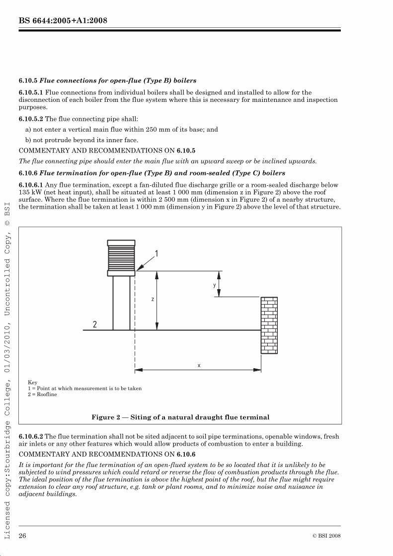
+A1:2008BS 6644:2005
Licensed copy:Stourbridge College, 01/03/2010, Uncontrolled Copy, © BSI
6.10.5 Flue connections for open-flue (Type B) boilers
6.10.5.1 Flue connections from individual boilers shall be designed and installed to allow for the disconnection of each boiler from the flue system where this is necessary for maintenance and inspection purposes.
6.10.5.2 The flue connecting pipe shall:
a) not enter a vertical main flue within 250 mm of its base; and
b) not protrude beyond its inner face.
COMMENTARY AND RECOMMENDATIONS ON 6.10.5
The flue connecting pipe should enter the main flue with an upward sweep or be inclined upwards.
6.10.6 Flue termination for open-flue (Type B) and room-sealed (Type C) boilers
6.10.6.1 Any flue termination, except a fan-diluted flue discharge grille or a room-sealed discharge below 135 kW (net heat input), shall be situated at least 1 000 mm (dimension z in Figure 2) above the roof surface. Where the flue termination is within 2 500 mm (dimension x in Figure 2) of a nearby structure, the termination shall be taken at least 1 000 mm (dimension y in Figure 2) above the level of that structure.
6.10.6.2 The flue termination shall not be sited adjacent to soil pipe terminations, openable windows, fresh air inlets or any other features which would allow products of combustion to enter a building.
COMMENTARY AND RECOMMENDATIONS ON 6.10.6
It is important for the flue termination of an open-flued system to be so located that it is unlikely to be subjected to wind pressures which could retard or reverse the flow of combustion products through the flue. The ideal position of the flue termination is above the highest point of the roof, but the flue might require extension to clear any roof structure, e.g. tank or plant rooms, and to minimize noise and nuisance in adjacent buildings.
Key1 = Point at which measurement is to be taken2 = Roofline
Figure 2 — Siting of a natural draught flue terminal
1
2
y
z
x
26 © BSI 2008
+A1:2008BS 6644:2005
Licensed copy:Stourbridge College, 01/03/2010, Uncontrolled Copy, © BSI
The flue termination of a fanned draught flue system is not critical with respect to the performance of the system. However, positions where the discharge of combustion products could cause a nuisance should be avoided, and guards should be fitted in positions that are readily accessible (see 6.10.11 and 6.10.12).
In all cases, flue termination positions have to provide correct dilution of the combustion products in order
6.10.7 Terminals for open-flue (Type B) boilers
A terminal shall be fitted to a flue if any dimension measured across the axis of the flue outlet is less than 170 mm.
The terminal shall be designed to have a minimum resistance to the egress of combustion products. In addition, there shall be effective protection against the entry of rain, snow, leaves, birds, etc.
COMMENTARY AND RECOMMENDATIONS ON 6.10.7
Additional information on flue terminals is given in Building Regulations Approved Document J [34] and BS EN 1856-1 and BS EN 1856-2.
The need for a terminal for larger flues than specified above is determined by local conditions. Effective protection against the entry of leaves and birds, etc, may be achieved by wire mesh guards.
The need to prevent rain ingress is less important where condensing boilers are used as the flue system will be fitted with drain facilities.
6.10.8 Sizing of the flue for open-flue (Type B) boilers
The flue system used shall be sized according to the total (net or gross) heat input of the boiler plant and designed so as to ensure safe removal of products of combustion to the outside atmosphere.
COMMENTARY AND RECOMMENDATION ON 6.10.8
appropriate heat input is used.
6.10.9 Surface temperatures for open-flue (Type B) and room-sealed (Type C) boilers
6.10.9.1 The boiler shall be installed in such a way that its operation does not cause the temperature of any combustible material in the vicinity of the boiler and its flue to exceed 65 °C.
6.10.9.2 The flue shall not be installed nearer than 50 mm to any combustible material, unless it passes through a roof, floor, ceiling, wall or partition constructed of combustible materials; in which case, it shall be enclosed in a sleeve of non-combustible material, and separated from the sleeve by an air space of not less than 25 mm.
6.10.9.3 The flue pipe shall be placed, shielded and supported such as to ensure that, whether the pipe is inside or outside the building, there is neither undue risk of accidental damage to the flue pipe nor undue danger to persons in or around the building.
6.10.10 Common flues for open-flue (Type B) boilers
6.10.10.1 Where two or more gas-fired boilers are to be connected to a common natural draught flue, the boilers shall be installed in the same room and shall have the same type of burner system. The flue shall be sized such as to ensure complete evacuation of the combustion products from the whole installation.
COMMENTARY AND RECOMMENDATIONS ON 6.10.10.1
In general, separate flues are to be preferred, especially if one boiler in a group is likely to operate more regularly than the others in the group.
6.10.10.2 Where one boiler is likely to be used more regularly or for longer periods than others in the group, it shall be connected at the point nearest the main flue.
6.10.10.3 A gas-fired boiler shall be installed in such a way that its products of combustion do not discharge into the same flue as the products of combustion from a solid-fuel-fired boiler.
to meet the requirements of the Clean Air Act [12] and the Environment Act [40].! "
! "Detailed information on the size and height of flues is given in BS 5854, IGE/UP/10 [15] and the 1956 ! " (see Annex F).
Flue sizing calculation methods may use either net or gross heat inputs. It is important to ensure that the
Clean Air Act Memorandum on chimney heights (third edition) [33]
27© BSI 2008
+A1:2008BS 6644:2005
Licensed copy:Stourbridge College, 01/03/2010, Uncontrolled Copy, © BSI
Similarly, the products of combustion from a solid-fuel-fired boiler shall not be permitted to discharge into a flue serving a gas-fired boiler.
COMMENTARY AND RECOMMENDATIONS ON 6.10.10.3
The combustion products from gas-fired boilers and liquid-fuel-fired boilers may discharge into a common flue provided that:
a) reference was made at the design stage to the boiler manufacturers or their instructions;
b) the common flue is of adequate size and construction;
c) the boilers are installed in the same room;
d) the burner systems of the gas- and liquid-fuel burning boilers are of the forced draught type;
e) the burner control equipment for both gas-firing and liquid-fuel-firing conforms to the relevant standards for the equipment; and
f) an adequate supply of air for combustion, and for ventilation of the room, is provided.
6.10.11 Mechanically assisted flues for open-flue (Type B) boilers
6.10.11.1 Boilers shall only be fitted with mechanically assisted flues following consultation with the boiler manufacturer as to the boiler’s suitability and the conditions necessary for these to operate correctly.
COMMENTARY AND RECOMMENDATIONS ON 6.10.11.1
The necessary information regarding the suitability and conditions might be readily available in the manufacturer’s instructions.
6.10.11.2 Where a fan is used to supplement the natural draught, the installation shall conform to the requirements of 6.10.11.3 to 6.10.11.7 and be carried out in accordance with the manufacturer’s instructions.
COMMENTARY AND RECOMMENDATIONS ON 6.10.11.2
Consideration should be given to provision of a fan to supplement the natural draught only where problems with flueing are expected because of construction difficulties, e.g. unavoidably long horizontal runs, restricted choice of terminal position or inadequate cross-sectional area of flue.
6.10.11.3 Any fan installed in a flue shall be of a size capable of handling all products of combustion, including excess air, from the boiler, by way of the downdraught diverter (where fitted), allowing for the total resistance of the system.
6.10.11.4 Any fan shall be installed in a position where it is accessible for maintenance.
6.10.11.5 Where a fan is fitted in the flue to assist the venting of the products of combustion, an automatic control shall be provided to cause the boiler to go to safety shut-down and lockout in the event of the fan failure or restriction of the mechanical extract system.
6.10.11.6 The fan shall not cycle on-off in response to a room thermostat. Where a fan is cycled on-off in response to a boiler thermostat or time control, a pre-purge facility shall be incorporated.
6.10.11.7 Flow-proving devices on any mechanically-assisted flue system shall be proved in the “no-air” position prior to pre-purge on the first on-line burner/boiler.
6.10.12 Fan diluted flues for open-flue (Type B) boilers
Where a fan diluted flue system is used, it shall be so designed as to dilute the products of combustion down to a level at which they can be discharged and dispersed from positions that would not otherwise be desirable or acceptable.
COMMENTARY AND RECOMMENDATIONS ON 6.10.12
Detailed information is given in Annex B and also in IGE/UP/10 [15] and the third edition of the 1956 Clear Air Memorandum on chimney heights [33].
6.11 Boiler assembly
6.11.1 Before installing the boiler, all the protective packing and seals shall be removed from the boiler and its ancillary equipment, including the gasways and waterways of safety controls and the valve seatings
28 © BSI 2008
+A1:2008BS 6644:2005
Licensed copy:Stourbridge College, 01/03/2010, Uncontrolled Copy, © BSI
of governors and relay valves. The manufacturer’s recommended methods of assembly and materials for jointing shall be used for those boilers assembled on site.
COMMENTARY AND RECOMMENDATIONS ON 6.11.1
For boilers which are site-assembled it should be noted that all middle sections might not be identical. Particular care should be taken to ensure that the order in which they are assembled is in accordance with the manufacturer’s instructions.
6.11.2 Sectional boilers assembled on site in accordance with the manufacturer’s instructions shall be subjected to a hydraulic pressure of 1.5 times the maximum allowable pressure for a period of 30 min without visible signs of distortion, damage or leakage.
COMMENTARY AND RECOMMENDATIONS ON 6.11.2
Before the hydraulic test is carried out, appropriate steps should be taken to isolate the boiler from any parts of the associated system that are not designed to withstand the specified test pressure.
6.12 Burner installation
Where the boiler and burner are delivered separately, the installation of the burner in the boiler shall be carried out in accordance with the manufacturer’s instructions.
COMMENTARY AND RECOMMENDATIONS ON 6.12
Particular attention should be given to the required clearances and access.
7 Inspection, commissioning and servicing
7.1 General
The commissioning engineer shall examine any relevant test certificates for the installation before commissioning is commenced.
7.2 Inspection
The installation shall be thoroughly inspected prior to commissioning, to ensure that the work has been carried out in accordance with Clause 6 and the manufacturer’s installation instructions. The commissioning engineer shall liaise with any other specialist engineers to ensure that the boiler installation and all associated systems operate correctly and safely. In addition, the commissioning engineer, in co-operation with any other specialist engineers, shall ensure that:
a) any open vents and safety valves are correctly located; and
b) the water system has been flushed, refilled, vented and, where required, pressurized.
COMMENTARY AND RECOMMENDATIONS ON 7.2
Attention is drawn to the Gas Safety (Installation and Use) Regulations [1], particularly those relating to:
a) the provision of air for ventilation and combustion (see 6.9);
b) the construction of the flue (see 6.10);
c) the correct location of any open vents and safety valves (see 6.3); and
d) the cleaning out of the waterways.
7.3 Commissioning
7.3.1 Commissioning shall be carried out in a series of logical steps in accordance with the manufacturer’s instructions for checking the operation of all controls, motors, pumps and valves prior to the admission of gas to the burner.
COMMENTARY AND RECOMMENDATIONS ON 7.3.1
A typical list of boiler checks to be carried out prior to commissioning the burner(s) is given in Annex C. Reference should also be made to the CIBSE Commissioning Code B [17] and IGE/UP/4 [36]. A suitable person to co-ordinate all aspects of the commissioning procedure should be appointed.
7.3.2 Gas shall be admitted to the burner for the live run commissioning procedure only after a complete and faultless dry run (see 7.3.3). Such a dry run shall include checks for the correct operation, setting and
29© BSI 2008
+A1:2008BS 6644:2005
Licensed copy:Stourbridge College, 01/03/2010, Uncontrolled Copy, © BSI
gas tightness of manual valves, safety shut-off valves, gas pressure switches, non-return valves, governors, and any other controls.
7.3.3 The burner shall be commissioned in a series of logical steps that check that the controls are operating correctly and that the air supplies are adequate for purging and combustion.
COMMENTARY AND RECOMMENDATIONS ON 7.3.3
A typical list of live run checks to be carried out is given in Annex D.
7.3.4 Unless otherwise stated by the manufacturer, a combustion analysis of the concentration of carbon dioxide and/or oxygen and carbon monoxide in the flue shall be carried out in accordance with Annex E.
7.3.5 The concentration of carbon monoxide in the dry air-free products shall not exceed 0.1% (1 000 ppm) or the value given in the manufacturer’s instructions, whichever is the lower.
COMMENTARY AND RECOMMENDATIONS ON 7.3.5
The method of calculating “dry air-free” concentration is given in Annex E.
7.3.6 When commissioning is completed, a record shall be made and left with the customer, stating:
a) the control and limit thermostat settings;
b) the air and gas pressure switch settings;
c) the governor outlet and burner manifold pressures at high and low fire; and
d) the carbon dioxide and/or oxygen concentrations in the flue gases at high and low fire and flue gas temperatures where taken, measured upstream of any downdraught diverter or stabilizer in accordance with the manufacturer’s instructions.
COMMENTARY AND RECOMMENDATIONS ON 7.3.6
It is recommended that this information is recorded in a “log book/servicing record” which is handed to the user or his representative on completion.
7.4 Advice to be given to the userNOTE Attention is drawn to the Gas Safety (Installation and Use) Regulations 1998 [1], which require the installer to leave for the use of the owner or occupier of the premises in which a boiler is installed all the manufacturer’s instructions.
7.4.1 The commissioning engineer shall ensure that:
a) brief user instructions for the safe operation and lighting of the boiler(s) are clearly provided on or adjacent to the boiler(s) and any remote control panels;
b) wiring diagrams for the boiler(s) and its ancillary controls are given to the owner or occupier of the premises or attached to the boiler(s);
c) the user or his representative is instructed in the safe operating and lighting procedures for the boiler(s); and
d) the user or his representative is instructed that extraneous materials shall not be stored in a purpose-constructed boiler room and that manufacturers clearance distances shall be maintained.
7.4.2 The commissioning engineer shall advise the user or his representative in writing of the method and frequency of servicing, the life of replaceable items and allied servicing aspects.
COMMENTARY AND RECOMMENDATIONS ON 7.4.2
This should include the handing over of any log book/servicing record referred to in the Commentary and Recommendations on 7.3.6.
7.4.3 The installer shall provide the user or his representative with drawings showing the position of the boiler(s), automatic controls, valves, pumps, water treatment plant, pipe runs and electrical circuits, as installed.
There shall be provision for quick identification of all pipes, valves and switches in order that their function may be readily understood.
COMMENTARY AND RECOMMENDATIONS ON 7.4.3
Copies of this information should be kept displayed in the boiler room.
30 © BSI 2008
+A1:2008BS 6644:2005
Licensed copy:Stourbridge College, 01/03/2010, Uncontrolled Copy, © BSI
7.5 Maintenance
7.5.1 The installer of the boiler shall advise the owner or occupier of the premises in writing of the importance of regular inspection and servicing by a competent person.
COMMENTARY AND RECOMMENDATIONS ON 7.5.1
If the premises are tenanted and the landlord owns the boiler, the landlord is required by the Gas Safety (Installation and Use) Regulations [1] to ensure that the boiler installation is checked for safety every 12 months.
7.5.2 The installer shall draw the user’s attention to the servicing instructions provided by the manufacturer and in particular shall stress that any servicing procedure shall incorporate determination of:
a) the effectiveness and integrity of the flue;
b) the effectiveness of the combustion air supply;
c) the heat input and operating pressure;
d) the safe operation of the boiler; and
e) combustion products analysis.
Where the premises in which the boiler is situated are leased, attention shall be drawn in writing to the necessity for notifying the person responsible for the premises of any defect in the boiler found during the servicing procedure.
COMMENTARY AND RECOMMENDATIONS ON 7.5.2
The importance of maintaining any log book/servicing record should be drawn to the attention of the owner or occupier of the premises in which the boiler is installed.
7.5.3 The installer shall supply a list of recommended spare parts to be kept by the user in the interests of maintaining continuity of the heat service.
31© BSI 2008
+A1:2008BS 6644:2005
Licensed copy:Stourbridge College, 01/03/2010, Uncontrolled Copy, © BSI
Annex A (Informative) Basis for the provision of combustion and cooling air to boiler houses and rooms in which commercial boilers are installed in accordance with this standard
A.1 Introduction
This annex gives the logic and reasoning for the ventilation openings to be included in this standard.
For open-flue (type B) boilers air is required for both combustion and cooling. For room-sealed (type C) boilers, only cooling air is required.
Open-flue boilers might be fitted with either a draught diverter or stabilizer, or with neither.
A.2 Data and assumptions
A.2.1 The following assumptions were made in calculating the ventilation requirements specified in this standard.
A.2.2 Boiler house temperature, as specified in 6.9.1.2:
— 40 °C at high level;— 32 °C at mid level; and— 25 °C at low level.
Air enters the boiler house/room at 15 ºC.
A.2.3 Fuel: Natural Gas (G20) Calorific Value (net) 34.02 MJ/m3 [EN 437] (9.45 kWh/m3).
A.2.4 Percentage of CO2 in the flue gases: 8.5 %.
A.2.5 Exit temperature of cooling air:
— no draught diverter — 40 °C— with draught diverter2) — mean temperature 36 °C.
A.2.6 Heat released into the boiler house: 1 % of the net heat input of the boiler(s)3) (0.01kW/kW of net heat input).
A.2.7 Speed of air through the ventilation openings: 2 m/sec.
A.2.8 Specific heat of air: 3.49 × 10⁻⁴ kWh/(m3K).
A.3 Volume of air required
A.3.1 Combustion air
For stoichiometric combustion the volume of air required to burn 1 unit volume of gas is 9.58 volumes (assumes air is 21% O2 and 79% N2). If the % CO2 in the flue gases is 8.5, then the air required to burn 1 volume of gas will be 13.2 volumes.
For G20 gas the air required per kW of heat input is calculated to be 3.89 × 10⁻⁴ m3/sec.
A.3.2 Cooling airNOTE It is assumed that the “combustion air” will not contribute significantly to cooling. The cooling effect of the combustion air is therefore ignored.
A.3.2.1 No draught diverter
In this case all the air for cooling is assumed to enter at 15 °C at low level and leave at 40 °C at high level.
From A.2.6 the heat to be removed is 0.01 kWh per kW of net heat input.
With an inlet air temperature of 15 °C and outlet temperature of 40 °C, the temperature rise is 25 K.
2) 50 % air leaves through draught diverter at mid level temperature of 32 °C and 50 % at high level temperature of 40 °C ; therefore “mean” exit temperature is 36 °C3) The 1 % includes for heat emitted from ancillary pipe-work and pumps within the boiler house/room.
32 © BSI 2008
+A1:2008BS 6644:2005
Licensed copy:Stourbridge College, 01/03/2010, Uncontrolled Copy, © BSI
Volume of air (m3) required to remove 0.01 kWh is given by the equation:
heat (kWh)/(specific heat (kWh/(m3K)) × temperature rise (K))
= 0.01 × 10⁴/(3.49 × 25) m3
= 1.146 m3.
Volume of air flow required (m3/sec) = 1.146/3 600 m3/sec
= 3.18 × 10⁻⁴ m3 /sec at 15 °C.
At the exit the air is at 40 °C and the volume of air is therefore greater by a factor of (273 + 40)/(273 + 15) which calculates to 1.09.
These air flow volumes are summarised in Table A.1.
Table A.1 — Cooling air for a boiler not fitted with a draught diverter
A.3.2.2 Fitted with draught diverter
In this case all the cooling air enters at 15 °C, but 50 % exits via the draught diverter at 32 °C and 50 % exits at 40 °C (see footnote 2). The mean leaving temperature is therefore 36 °C, i.e. a mean temperature rise of 21 K.
Volume of air (m3) required to remove 0.01 kWh is given by the equation:
heat (kWh)/(specific heat (kWh/(m3K)) × temperature rise (K))
= 0.01 × 10⁴/(3.49 × 21) m3
= 1.36 m3.
Volume of air flow required (m3/sec)= 1.36/3 600 m3/sec
= 3.79 × 10⁻⁴ m3/sec.
50 % of 3.79 × 10⁻⁴ m3/sec air flow exits via the draught diverter at 32 °C and 50 % will exit from the high level opening at 40 °C. The temperature correction of 1.09 (see A.3.2.1) is only necessary for the 50 % portion of air that exits at 40 °C, i.e. 1.9 × 1.09 = 2.07 × 10⁻⁴ m3/sec.
These air flow volumes are summarised in Table A.2.
Table A.2 — Cooling air for a boiler fitted with a draught diverter
A.4 Ventilation requirements
A.4.1 Natural ventilation
Natural ventilation necessitates high and low level openings of sufficient free-area to be provided to allow the combustion and cooling air to enter and the heated cooling air to exit the boiler house/room. Ventilation
Cooling air Temperature°C
Airflow per kW net heat input(m3/sec)
Inlet 15 3.18 × 10⁻⁴
Outlet 40 3.47 × 10⁻⁴
Cooling air Temperature°C
Airflow per kW net heat input(m3/sec)
Inlet 15 3.79 × 10⁻⁴
Outlet (via draught diverter)a 32 1.90 × 10⁻⁴
Outlet (high level) 40 2.07 × 10⁻⁴
a No correction is necessary for temperature for cooling air exiting via the draught diverter.
33© BSI 2008
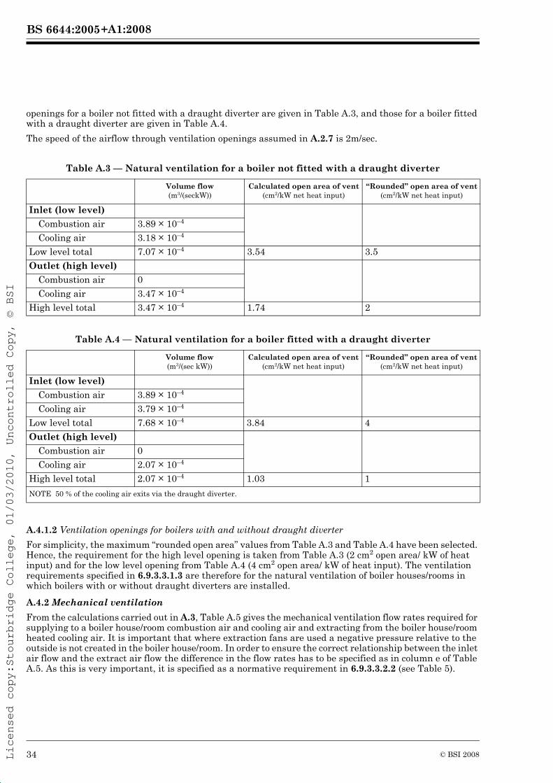
+A1:2008BS 6644:2005
Licensed copy:Stourbridge College, 01/03/2010, Uncontrolled Copy, © BSI
openings for a boiler not fitted with a draught diverter are given in Table A.3, and those for a boiler fitted with a draught diverter are given in Table A.4.
The speed of the airflow through ventilation openings assumed in A.2.7 is 2m/sec.
Table A.3 — Natural ventilation for a boiler not fitted with a draught diverter
Table A.4 — Natural ventilation for a boiler fitted with a draught diverter
A.4.1.2 Ventilation openings for boilers with and without draught diverter
For simplicity, the maximum “rounded open area” values from Table A.3 and Table A.4 have been selected. Hence, the requirement for the high level opening is taken from Table A.3 (2 cm2 open area/ kW of heat input) and for the low level opening from Table A.4 (4 cm2 open area/ kW of heat input). The ventilation requirements specified in 6.9.3.3.1.3 are therefore for the natural ventilation of boiler houses/rooms in which boilers with or without draught diverters are installed.
A.4.2 Mechanical ventilation
From the calculations carried out in A.3, Table A.5 gives the mechanical ventilation flow rates required for supplying to a boiler house/room combustion air and cooling air and extracting from the boiler house/room heated cooling air. It is important that where extraction fans are used a negative pressure relative to the outside is not created in the boiler house/room. In order to ensure the correct relationship between the inlet air flow and the extract air flow the difference in the flow rates has to be specified as in column e of Table A.5. As this is very important, it is specified as a normative requirement in 6.9.3.3.2.2 (see Table 5).
Volume flow(m3/(seckW))
Calculated open area of vent(cm2/kW net heat input)
“Rounded” open area of vent(cm2/kW net heat input)
Inlet (low level)
Combustion air 3.89 × 10⁻⁴
Cooling air 3.18 × 10⁻⁴
Low level total 7.07 × 10⁻⁴ 3.54 3.5
Outlet (high level)
Combustion air 0
Cooling air 3.47 × 10⁻⁴
High level total 3.47 × 10⁻⁴ 1.74 2
Volume flow(m3/(sec kW))
Calculated open area of vent(cm2/kW net heat input)
“Rounded” open area of vent(cm2/kW net heat input)
Inlet (low level)
Combustion air 3.89 × 10⁻⁴
Cooling air 3.79 × 10⁻⁴
Low level total 7.68 × 10⁻⁴ 3.84 4
Outlet (high level)
Combustion air 0
Cooling air 2.07 × 10⁻⁴
High level total 2.07 × 10⁻⁴ 1.03 1
NOTE 50 % of the cooling air exits via the draught diverter.
34 © BSI 2008
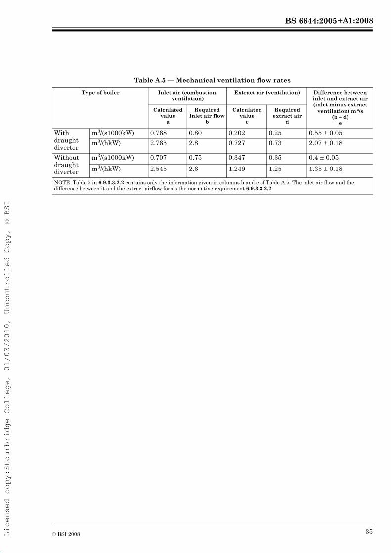
+A1:2008BS 6644:2005
Licensed copy:Stourbridge College, 01/03/2010, Uncontrolled Copy, © BSI
Table A.5 — Mechanical ventilation flow rates
Type of boiler Inlet air (combustion, ventilation)
Extract air (ventilation) Difference between inlet and extract air (inlet minus extract
ventilation) m 3/s(b – d)
e
Calculated value
a
Required Inlet air flow
b
Calculated value
c
Required extract air
d
With draught diverter
m3/(s1000kW) 0.768 0.80 0.202 0.25 0.55 ú 0.05
m3/(hkW) 2.765 2.8 0.727 0.73 2.07 ú 0.18
Without draught diverter
m3/(s1000kW) 0.707 0.75 0.347 0.35 0.4 ú 0.05
m3/(hkW) 2.545 2.6 1.249 1.25 1.35 ú 0.18
NOTE Table 5 in 6.9.3.3.2.2 contains only the information given in columns b and e of Table A.5. The inlet air flow and the difference between it and the extract airflow forms the normative requirement 6.9.3.3.2.2.
35© BSI 2008
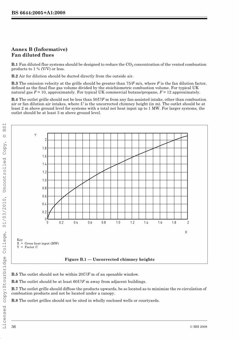
+A1:2008BS 6644:2005
Licensed copy:Stourbridge College, 01/03/2010, Uncontrolled Copy, © BSI
Annex B (Informative) Fan diluted flues
B.1 Fan diluted flue systems should be designed to reduce the CO2 concentration of the vented combustion products to 1 % (V/V) or less.
B.2 Air for dilution should be ducted directly from the outside air.
B.3 The emission velocity at the grille should be greater than 75/F m/s, where F is the fan dilution factor, defined as the final flue gas volume divided by the stoichiometric combustion volume. For typical UK natural gas F = 10, approximately. For typical UK commercial butane/propane, F = 12 approximately.
B.4 The outlet grille should not be less than 50U/F m from any fan-assisted intake, other than combustion air or fan dilution air intakes, where U is the uncorrected chimney height (in m). The outlet should be at least 2 m above ground level for systems with a total net heat input up to 1 MW. For larger systems, the outlet should be at least 3 m above ground level.
B.5 The outlet should not be within 20U/F m of an openable window.
B.6 The outlet should be at least 60U/F m away from adjacent buildings.
B.7 The outlet grille should diffuse the products upwards, be so located as to minimize the re-circulation of combustion products and not be located under a canopy.
B.8 The outlet grilles should not be sited in wholly enclosed wells or courtyards.
KeyX = Gross heat input (MW)Y = Factor U
Figure B.1 — Uncorrected chimney heights
2
1.8
1.6
1.4
1.2
1.0
0.8
0.6
0.4
0.2
00 0.2 0.4 0.6 0.8 1.0 1.2 1.4 1.6 1.8 2
Y
X
36 © BSI 2008
+A1:2008BS 6644:2005
Licensed copy:Stourbridge College, 01/03/2010, Uncontrolled Copy, © BSI
Annex C (Informative) Checks to be carried out on the boiler prior to commissioning
The following is a typical list of checks to be carried out by the commissioning engineer prior to commissioning the boiler installation:
a) with the boiler’s(’) main manual gas isolating valve(s) closed, and the electricity supply switched off:
1) check with the gas supplier or the owner/occupier of the premises in which the boiler is installed that the meter installation is operational;
2) ensure that the gas installation pipework to the boiler(s) has been correctly purged and tested for gas tightness;NOTE 1 Guidance is given in IGE/UP/1 [37] and IGE/UP/1A [38].
3) check the closure and gas-tightness of the boiler’s(’) main gas isolating valve(s);
4) check that all electrical supplies are isolated;
5) check electrical earth continuity between the boiler’s(’) gas pipework and the mains supply;
6) check the electrical components are of the correct voltage range, particularly the low voltage ancillary controls;
7) check and adjust fan belt tensions;
8) check the fan/pump motor currents and adjust the starter overload settings; and
9) check the ventilation air supply is correct.
b) with the boiler’s(’) main manual gas isolating valve(s) closed and the electricity supply switched on:
1) check that the direction of rotation of the fan(s)/pump(s) is correct;
2) check and, where necessary and possible, adjust the air and water flow failure switch(es);
3) check for the correct connection and operation of all systems components and controls;
4) check the operation and interlocking of any air inlet and extract fans; and
5) check and adjust the setting of air and water flows.
c) with boiler’s(’) main manual gas isolating valve(s) open, the burner’s(’) isolating valve(s) closed and the electricity supply switched on:
1) check the gas tightness of the installation downstream of the boiler’s(’) main manual gas isolating valve(s), using a leak detection fluid, e.g. soap solution; and
2) check the gas-tightness of all manual and automatic valves.
Annex D (Informative) Typical live run checks
The following is a typical list of live run checks to be carried out by the commissioning engineer during commissioning.
a) After a faultless dry run, carry out a safe start check in accordance with the manufacturer’s instructions.
b) Simulate a pilot or start gas flame failure and check that the flame safeguard system proceeds to lockout, e.g. by turning off the pilot gas supply.
c) After checking that the start gas flame is correctly sited and adequate to light the main flame, allow gas to flow to the burner, having first ensured that there is adequate combustion air available.
d) If the main flame fails to ignite, repeat the complete lighting procedure ensuring that adequate time is allowed to purge the combustion chamber.
e) After satisfactory ignition of the main flame, adjust the air/gas ratio to ensure correct combustion and flame shape.
f) Adjust the burner cycle between high and low fire and check all controls and interlocks for correct operation.
37© BSI 2008
+A1:2008BS 6644:2005
Licensed copy:Stourbridge College, 01/03/2010, Uncontrolled Copy, © BSI
g) Check the gas rate to the boiler using, for example, the primary meter.
h) Adjust the cycle of the boiler several times from the “off” position to the “high-fire” position to test for reliable operation.
following gives guidance on the procedure to be adopted.
E.1 A suitable sample probe shall be inserted into the primary flue of the boiler (i.e. upstream of any draught diverter or draught stabiliser). Any port through which a probe is inserted shall be capable of being adequately sealed after use.
COMMENTARY AND RECOMMENDATIONS ON E.1
The manufacturer might have provided a suitable port for inserting a sample probe. If one is provided, this should be used.
E.2 It shall be ensured that there is sufficient heating load on the system to allow the boiler to be operated for the test period
second test shall be carried out with the burner adjusted to the low fire rate.
shall be operated at nominal heat input until stable conditions have been achieved before any
NOTE It might be necessary to route the sample tube out of the balanced compartment or enclosure.
E.5 The carbon dioxide (CO2) [or oxygen (O2 )] and carbon monoxide (CO) concentrations in the flue gases shall be measured using equipment suitable for flue gas analysis, e.g. a gas analyser conforming to BS 7927.
E.6 Where the carbon dioxide concentration has been measured, the “dry, air-free” percentage of carbon monoxide (CO) shall be calculated using the formula given by:
where:
The concentrations of (CO2)N in Group H, P and B gases, in percentages, are given in Table E.1.
CO is the carbon monoxide concentration of the dry, air-free combustion products in percent;
(CO2)N is the maximum carbon dioxide concentration of the dry, air-free combustion products in percent;
(CO)M and (CO2)M are the measured concentrations in the samples taken during the combustion test, both expressed in percent.
CO (dry, air-free)CO( )M CO2( )N×
CO2( )M---------------------------------------------=
Combustion products analysisAnnex E (Normative)
E.1 Flue gas analysis shall be carried out in accordance with the manufacturer’s instructions. The
measurements are taken.
manufacturer. If there is a suitably placed gas meter, the heat input shall be checked. Where applicable, a E.3 The boiler shall be adjusted to operate at the maximum nominal heat input stated by the
E.4 The door(s) of the boiler house/room or balanced compartment or enclosure shall be closed. The boiler
38 © BSI 2008
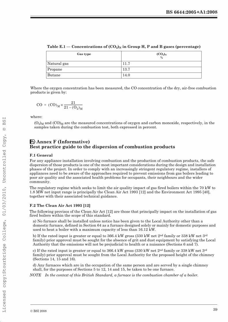
+A1:2008BS 6644:2005
Licensed copy:Stourbridge College, 01/03/2010, Uncontrolled Copy, © BSI
Table E.1 — Concentrations of (CO2)N in Group H, P and B gases (percentage)
Where the oxygen concentration has been measured, the CO concentration of the dry, air-free combustion products is given by:
where:
(O2)M and (CO)M are the measured concentrations of oxygen and carbon monoxide, respectively, in the samples taken during the combustion test, both expressed in percent.
Gas type (CO2)N
%
Natural gas 11.7
Propane 13.7
Butane 14.0
CO CO( )M21
21 O2( )M–-----------------------------×=
Best practice guide to the dispersion of combustion products
F.1 GeneralFor any appliance installation involving combustion and the production of combustion products, the safe dispersion of those products is one of the most important considerations during the design and installation
appliances need to be aware of the approaches required to prevent emissions from gas boilers leading to poor air quality and the associated health problems for occupants, their neighbours and the wider community.The regulatory regime which seeks to limit the air quality impact of gas fired boilers within the 70 kW to 1.8 MW net input range is principally the Clean Air Act 1993 [12] and the Environment Act 1995 [40], together with their associated technical guidance.
F.2 The Clean Air Act 1993 [12]The following provisos of the Clean Air Act [12] are those that principally impact on the installation of gas
a) No furnace shall be installed unless notice has been given to the Local Authority other than a domestic furnace, defined in Section 64 as a furnace designed solely or mainly for domestic purposes and used to heat a boiler with a maximum capacity of less than 16.12 kW.b) If the rated input is greater or equal to 366.4 kW gross (330 kW net 2nd family or 338 kW net 3rd family) prior approval must be sought for the absence of grit and dust equipment by satisfying the Local Authority that the emissions will not be prejudicial to health or a nuisance (Sections 6 and 7).c) If the rated input is greater or equal to 366.4 kW gross (330 kW net 2nd family or 338 kW net 3rd family) prior approval must be sought from the Local Authority for the proposed height of the chimney (Sections 14, 15 and 16).d) Any furnaces which are in the occupation of the same person and are served by a single chimney
NOTE In the context of this British Standard, a furnace is the combustion chamber of a boiler.
phases of the project. In order to comply with an increasingly stringent regulatory regime, installers of
!Annex F (Informative)
fired boilers within the scope of this standard.
shall, for the purposes of Sections 5 to 12, 14 and 15, be taken to be one furnace.
39© BSI 2008
+A1:2008BS 6644:2005
The principal guidance for the calculation of chimney heights is contained within the Third edition of the Chimney Heights Memorandum [33].This Memorandum [33] is not part of the Clean Air Act legislation and its continued reference to the 1956 version of the Act leads to confusion and the mistaken belief that it is obsolete. The document was produced specifically for dealing with conventional combustion plant running on fossil fuels and for which either sulphur dioxide or nitrogen oxides were the major pollutants. It has been updated twice since its first publication and, although further updates are unlikely, recent studies [41] have confirmed that it remains, in general, protective of air quality and should continue to be used for gas fired appliances. These recent studies [41] and the Local Authority specialist advice web site provided by Defra [42] also conclude that the use of the Memorandum [33] can be expanded to cover types of boiler (e.g. room sealed and modular) that are not included in the latest (1981) revision. For room sealed boilers specifically, chimney heights and their placement with respect to nearby buildings, ventilation inlets, opening windows, etc., should be determined by direct application of the Chimney Heights Memorandum [33] in the same manner as for any other flue, since the nature and quantity of the pollutants in the products of combustion are the same. For the majority of installations in the gross input range of 150 kW (135 kW net) to 2 MW (1.8 MW net), the Memorandum [33] will be the appropriate guidance to use.Further guidance on emissions from more complicated non-fossil fuel burning plant is given in Technical
F.3 The Environment Act 1995 [40]Section 80 of the Environment Act [40] requires the development of a National Air Quality Strategy [44] which includes the formulation of national air quality objectives. The Strategy is reviewed and updated to incorporate the measures required to comply with the European Directives on ambient air quality, as well as national policies which set limits and target values for air pollutants.The achievement of the national air quality objectives is a material matter for consideration in planning decisions. When a planning application is received, the Authority concerned will need to be satisfied that the dispersion of the emissions from any boiler is sufficient to avoid significant degradation of air quality. The chimney height and discharge point for the combustion products of the boiler should be designed to avoid any likelihood of significant air quality impact.Technical guidance [45] for air quality management is available and provides screening nomograms to assess whether the effective height of a chimney will avoid significant degradation of air quality for a given maximum emission rate (expressed as tonnes per year) of nitrogen oxides. It should be noted that the maximum emission rate might not occur when the boiler is operating at full load and consultation with the manufacturer is required to establish the appropriate value to use. As the Technical Guidance document is periodically reviewed and nomograms updated, the most recently published version should always be used. The nomograms assume a combustion products velocity of at least 10 m/s and the absence of significant building and topography effects. It may be appropriate to use the methods in the Chimney Heights Memorandum to take these effects into account; however, in some cases, dispersion modelling should be used following consultation with the Local Authority.
F.4 Best practice guidance notesF.4.1 Determining the overall inputs to be used in chimney calculationsIn recent years, due to ever rising outputs, gas boilers once regarded as domestic only, particularly of the wall hung, room sealed, modulating, condensing and high efficiency types, are being used in non-domestic applications. Consequently, the heating and hot water demands of commercial buildings of all sizes are being increasingly satisfied by the installation of these types of boilers, in modular format, leading to an array of adjacent terminals discharging combustion products at low level. If, individually, the boilers have a gross input of less than 366.4 kW, it may be deemed that they do not require chimney height approval under the Clean Air Act [12] when referred to F.2b), c) and d). There is a significant risk, however, that such installations of multiple boilers might lead to local exceedences of the prescribed annual average objective for nitrogen dioxide in places where members of the public might be regularly exposed close to the point of discharge. The products of combustion from room sealed boilers are not diluted and the constituents are the same as for any type of gas boiler, including those of similar size regarded as “conventional” (i.e. for connection to a natural draught chimney) where a low level discharge would never have been considered. The satisfactory dispersion of the products of combustion is further complicated when using modulating and high/low boilers since the discharge velocity will vary. At maximum firing rate,
40 © BSI 2008
Guidance Note (Dispersion) D1 [43], which is complementary to the Memorandum [33].
Licensed copy:Stourbridge College, 01/03/2010, Uncontrolled Copy, © BSI
+A1:2008BS 6644:2005
41
the products will tend to be blown well away from the building wall, whereas at minimum firing rate the products might drift up the wall and into, for example, an open window.Where multiple boilers are installed adjacent to one another in the same boiler house and discharge their products of combustion individually through the same wall or adjacent walls into the same external region, the total input of all the boilers should be used to determine chimney height. It might be possible to proportion the total input if some of the boilers are to discharge their products of combustion through opposing walls or adjoining walls forming an external corner on the outside. If there is an existing second boiler house immediately adjacent, it might be necessary to include these boiler(s) in the total input depending on the flue system.
F.4.2 Inputs below 150 kW grossIf the overall input as determined in F.4.1 is between 70 kW net (78 kW gross) and 135 kW net (150 kW gross) for 2nd family gases or 138 kW net (150 kW gross) for 3rd family gases, the Chimney Heights Memorandum does not apply and the manufacturer’s instructions should be followed to ensure the correct type of flue/chimney is fitted. For those boilers that are specifically certified for horizontal termination, low level discharge of the products of combustion should be possible. If the individual rating of the boiler(s) is below 70 kW net input, the spacing and positioning of the terminals should conform to BS 5440-1. The Building Regulations also cover the spacing and positioning of terminals. If the individual rating of one of the boiler(s) is 70 kW net input or above, the spacing and positioning of the terminal should conform to IGE/UP/10 [15]. When the boiler rating(s) and flue termination positioning are finalized, the appropriate Local Authority should be advised of the proposed installation.
F.4.3 Inputs between 150 kW and 366.4 kW grossIf the overall input as determined in F.4.1 is between 135 kW net (150 kW gross) and 330 kW net (366.4 kW gross) for 2nd family gases or between 138 kW net (150 kW gross) and 338 kW net (366.4 kW gross) for 3rd family gases, the Chimney Heights Memorandum [33] or equivalent (IGE/UP/10 [15]) should be used to determine the uncorrected chimney height required for the boiler(s), regardless of type. The height(s) should then be corrected for building effects and the overriding minimum requirements in the Memorandum. When the boiler rating(s) and flue termination positioning are formulated, the appropriate Local Authority should be advised of the proposed installation.Where there are complicated structures and/or difficult topography to consider, it might be necessary to use additional technical guidance available from a specialist web site provided by Defra [42], which might involve dispersion modelling.In circumstances where suitable chimney heights cannot be easily provided, site specific dispersion modelling might be necessary. In these cases, it is important that the appropriate Local Authority is consulted at an early stage in the design in order to establish that the proposed flue discharge positions are acceptable and will not cause significant local exceedences of air quality objectives.Where agreement is reached with the Local Authority, this should be recorded in a reproducible format as competent people involved at the latter stages of the project (i.e. the commissioning engineer) will ask for proof before allowing products of combustion to be discharged in an apparently non-compliant position.
F.4.4 Inputs above 366.4 kW gross
nd rd
If the overall input as determined in F.4.1 is greater than 330 kW net (366.4 kW gross) for 2nd family gases or 338 kW net (366.4 kW gross) for 3rd family gases, the Chimney Heights Memorandum [33] or equivalent (IGE/UP/10 [15]) should be used to determine the uncorrected chimney height required for the boiler(s), regardless of type. The height(s) should then be corrected for building effects and the overriding minimum requirements in the Memorandum. When the boiler rating(s) and flue termination positioning are finalized, the appropriate Local Authority should be advised of the proposed installation.Where there are complicated structures and/or difficult topography to consider, it might be necessary to use additional technical guidance available from a specialist web site provided by Defra [42], which might involve dispersion modelling.
© BSI 2008
If the total input of the boiler(s) discharging through a single chimney is greater than 330 kW net family gases the Chimney
Heights Memorandum [33] or equivalent (IGE/UP/10 [15]) should be used to determine the uncorrected (366.4kW gross) for 2 family gases or 338 kW net (366.4 kW gross) for 3
chimney height required for the boiler(s), regardless of type. The height(s) should then be corrected for building effects and the overriding minimum requirements shown in the Memorandum. When the boiler
Local Authority for approval of the proposed installation.rating(s) and flue termination positioning are finalized, the details should be submitted to the appropriate
Licensed copy:Stourbridge College, 01/03/2010, Uncontrolled Copy, © BSI
+A1:2008BS 6644:2005
42
In circumstances where suitable chimney heights cannot be easily provided, site specific dispersion modelling might be necessary. In these cases, it is important that the appropriate Local Authority is consulted at an early stage in the design in order to establish that the proposed flue discharge positions are acceptable and will not cause significant local exceedences of air quality objectives.Where agreement is reached with the Local Authority, this should be recorded in a reproducible format as competent people involved at the latter stages of the project (i.e. the commissioning engineer) will ask for proof before allowing products of combustion to be discharged in an apparently non-compliant position.
F.4.5 Condensing boilers
Condensing boilers are the standard requirement for heating installations and benefit the environment with their increased energy efficiency. Because of increased energy efficiency, their products of combustion can be discharged at a low temperature that results in much reduced buoyancy and momentum. Recent studies and advice suggest that, although the target efflux velocity in the Chimney Heights Memorandum [33] might not be met, the chimney height determined by the Memorandum will normally be sufficient for adequate dispersion for boiler(s) up to approximately 1 MW net input provided that the NOx is less than 70 mg/kWh and the chimney termination is above roof level and conforms to BS 6644:2005, 6.10.6 and 6.10.7. Boiler(s) not fulfilling these criteria might require more detailed assessment and dispersion modelling. The appropriate Local Authority should be consulted."
© BSI 2008Licensed copy:Stourbridge College, 01/03/2010, Uncontrolled Copy, © BSI
ent (in
nput not nce of
e to fire
practice
d above.
7.5 kW
p
ted hose
g water
tect and
he upper
pliances.
ion.
imneys
on of
Part 4 xplosive
Part 5
+A1:2008BS 6644:2005
Licensed copy:Stourbridge College, 01/03/2010, Uncontrolled Copy, © BSI
Bibliography
Standards publications
BS 5422:2001, Method for specifying thermal insulating materials on pipes, ductwork and equipmthe temperature range –40 °C to +700 °C).
BS 5440-1:2000, Installation and maintenance of flues and ventilation for gas appliances of rated iexceeding 70kW net (1st, 2nd and 3rd family gases) — Specification for installation and maintenaflues.
BS 5588-0:1996, Fire precautions in the design, construction and use of buildings — Part 0: Guidsafety codes of practice for particular premises/applications.
BS 5588-1:1990, Fire precautions in the design, construction and use of buildings — Part 1: Code offor residential buildings.
BS 5885-1, Automatic gas burners — Part 1: Specification for burners with input rating 60 kW an
BS 5885-2, Automatic gas burners — Part 2: Specification for packaged burners with input ratingup to but excluding 60kW.
BS 6448, Specification for gas appliance governors of DN greater than 50 and for inlet pressures uto 200 mbar.
BS 6501-1:2004, Metal hose assemblies — Part 1: Guidance on the construction and use of corrugaassemblies.
BS 6700:1997, Specification for design, installation, testing and maintenance of services supplyinfor domestic use within buildings and their curtilages.4)
BS 6880-1:1988, Code of practice for low temperature hot water heating systems of output greater than 45 kW — Part 1: Fundamental and design considerations.
BS 6880-2:1988, Code of practice for low temperature hot water heating systems of output greater than 45 kW — Part 2: Selection of equipment.
BS 7927:1998, Heating appliances for domestic applications — Portable apparatus designed to demeasure specific combustion flue gas products — Requirements.
BS EN 88:1991, Pressure governors for gas appliances for inlet pressures up to 200 mbar.
BS EN 294:1992, Safety of machinery. Safety distances to prevent danger zones being reached by tlimbs.
BS EN 437:2003, Specification for test gases, test pressures and categories of appliance, for gas ap
BS EN 1443:1999, Chimneys — General requirements.
BS EN 13084-1:2000, Free-standing industrial chimneys — Part 1: General requirements.
BS EN 13084-2:2001, Free-standing industrial chimneys — Part 2: Concrete chimneys.
BS EN 13084-4:2002, Free-standing industrial chimneys — Part 4: Brick liners design and execut
BS EN 13384-1:2002, Chimneys — Thermal and fluid dynamic calculation methods — Part 1: Chserving one appliance.
BS EN 13502:2002, Chimneys — Requirements and test methods for clay/ceramic flue terminals.
BS EN 60079-10:2003, Electrical apparatus for explosive gas atmospheres — Part 10: Classificatihazardous areas.
BS EN 61779-4:2000, Electrical apparatus for the detection and measurement of flammable gases —Performance requirements for group II apparatus indicating a volume fraction up to 100 % lower elimit.
BS EN 61779-5:2000, Electrical apparatus for the detection and measurement of flammable gases —Performance requirements for group II apparatus indicating a volume fraction up to 100 % gas.
4) BS 6700 is to be superseded by all five parts of BS EN 806 when these are published. At the time of publication of BS 6644:2005, only BS EN 806-1 and BS EN 806-2 were published.
43© BSI 2008
prEN 139
prEN 146overflow
DD 221:1
PD 1749:evacuatio
Other p
[1] GREAThe Stat
[2] GREASR 2004,
[3] GREAStationer
[4] GREAThe Stat
[5] GREAStationer
[6] GREAStationer
[7] NORTSR 2000
[8] GREAOffice.
[9] GREANo. 1148
[10] GREOffice.
[11] GREStationer
[12] GRE
[13] GRELondon:
[14] GRESI 2002,
[15] INSTin indust
[16] HEAinstallati
[17] CHA2002.
[18] HEAto noise,
[19] HEAappliancGuidance
5) Available
+A1:2008BS 6644:2005
44Licensed copy:Stourbridge College, 01/03/2010, Uncontrolled Copy, © BSI
59:2005, Anti-pollution check valves — DN 6 to DN 250 inclusive Family E, type A, B, C and D.
22:2004, Devices to prevent pollution by backflow of potable water — Air gap with circular (restricted) — Family A, type F.
997, General guidance for the marking of gas appliances.
2001, European scheme for the classification of gas appliances according to the method of n of the products of combustion (types).
ublications
T BRITAIN: The Gas Safety (Installation and Use) Regulations 1998, SI 1998, No. 2451, London: ionery Office.
T BRITAIN. The Gas Safety (Installation and Use) Regulations (Northern Ireland) 2004, No. 63, London: The Stationery Office.
T BRITAIN: The Gas Appliances (Safety) Regulations 1995, SI 1995, No. 1629, London: The y Office.
T BRITAIN: The Boiler (Efficiency) Regulations 1993, SI 1993, No. 3083, as amended, London: ionery Office.
T BRITAIN: The Building Regulations 2000, SI 2000, No. 2531, as amended, London: The y Office.
T BRITAIN: The Building (Scotland) Regulations 2004, SSI 2004, No. 406, London: The y Office.
HERN IRELAND: The Building Regulations (Northern Ireland) Statutory Rules 2000, No. 389.
T BRITAIN: Pressure Equipment Regulations 1999, SI 1990, No. 2179, London: The Stationery
T BRITAIN: The Water Supply (Water Fittings) Regulations 1999, as amended, SI 1999, , London: The Stationery Office.
AT BRITAIN: Health and Safety at Work etc. Act 1974, as amended, London: The Stationery
AT BRITAIN: The Electricity at Work Regulations 1989, SI 1989, No. 635, London: The y Office
AT BRITAIN: The Clean Air Act 1993, London: The Stationery Office
AT BRITAIN: The Asbestos (Prohibitions) Regulations 1992, SI 1992, No. 3067, as amended, The Stationery Office.
AT BRITAIN: The Dangerous Substances and Explosive Atmospheres Regulations 2002, No. 2776, London: The Stationery Office.
ITUTION OF GAS ENGINEERS AND MANAGERS: IGE/UP/10, Installation of gas appliances rial and commercial premises, Part 1 (Second edition), Amendment 1, to be published in 2005.
LTH AND SAFETY COMMISSION: Approved Code of Practice: Standard of training in safe gas ons, 1987.
RTERED INSTITUTION OF BUILDING SERVICES ENGINEERS: Commissioning Code B,
LTH AND SAFETY EXECUTIVE: Code of practice for reducing the exposure of employed persons Sudbury: HSE Books5): 1989.
LTH AND SAFETY EXECUTIVE: L56, Safety in the installation and use of gas systems and es. The Gas Safety (Installation and Use) Regulations 1998, Approved Code of Practice and (Second Edition), Sudbury: HSE Books5).
from HSE Books, PO Box 1999, Sudbury, Suffolk, CO10 6FS.
© BSI 2008
imation es
pressure the
ork,
ers and
sidential
lation,
ipment uidance.
us ce. HSE
tion ce.
pair and nd
nces and
bstances
s.
n: The
Office,
fired
purging
d direct
proved in
+A1:2008BS 6644:2005
Licensed copy:Stourbridge College, 01/03/2010, Uncontrolled Copy, © BSI
[20] EUROPEAN COMMUNITIES, Council Directive 90/396/EEC of 29 June 1990 on the approxof the laws of the Member States relating to appliances burning gaseous fuels (the “Gas AppliancDirective”), Luxembourg: Office for Official Publications of the European Communities, 1999 (OJ No. L196, 26.07.1990).
[21] EUROPEAN COMMUNITIES, Council Directive 99/36/EC of 29 April 1999 on transportable equipment (the “Pressure Equipment Directive”), Luxembourg: Office for Official Publications ofEuropean Communities, 1999 (OJ No. L138, 01.06.1999).
[22] INSTITUTION OF GAS ENGINEERS AND MANAGERS: IGE/UP/2, Gas installation pipewboosters and compressors on industrial and commercial premises, London: 1994.
[23] THE LP GAS ASSOCIATION: Code of practice No. 24.6: The Use of Propane in Cylinders at Commercial and Industrial Premises, Ringwood: 2000.
[24] THE LP GAS ASSOCIATION: Code of practice No. 7: Storage of Full and Empty LPG CylindCartridges, Ringwood: 2004.
[25] THE LP GAS ASSOCIATION: Code of practice No. 24.1: The Use of Propane in Cylinders at RePremises, Ringwood: 1998.
[26] THE LP GAS ASSOCIATION: Code of practice No. 22: LPG piping, system design and instalRingwood: 2002.
[27] HEALTH AND SAFETY EXECUTIVE: Approved Code of Practice L134: Design of plant equand workplaces; Dangerous Substances and Explosive Atmospheres Regulations 2002. AcoP and GMiddlesborough: HSE Books.
[28] HEALTH AND SAFETY EXECUTIVE: Approved Code of Practice L 135: Storage of dangerosubstances; Dangerous Substances and Explosive Atmospheres Regulations 2002. AcoP and GuidanBooks.6)
[29] HEALTH AND SAFETY EXECUTIVE: Approved Code of Practice L 136: Control and mitigamethods; Dangerous Substances and Explosive Atmospheres Regulations 2002. AcoP and GuidanMiddlesborough: HSE Books.
[30] HEALTH AND SAFETY EXECUTIVE: Approved Code of Practice L 137: Safe maintenance, recleaning procedures; Dangerous Substances and Explosive Atmospheres Regulations 2002. AcoP aGuidance. Middlesborough: HSE Books.
[31] HEALTH AND SAFETY EXECUTIVE: Approved Code of Practice L 138: Dangerous SubstaExplosive Atmospheres Regulations 2002. AcoP and Guidance. Middlesborough: HSE Books.
[32] INDG 370: Fire and explosion; How safe is your workplace? A short guide to the Dangerous Suand Explosive Atmospheres Regulations 2002. Sudbury: HSE Books6): 2002.
[33] GREAT BRITAIN: Third edition of the 1956 Clean Air Act Memorandum — Chimney Height
[34] Approved Document J, Combusion appliances and fuel storage systems (2002 Edition), LondoStationery Office.
[35] Approved Document J: 2002 Edition, Guidance and Supplementary Information on the UK Implementation of European Standards for Chimneys and Flues (second edition), The StationeryLondon: 2004.
[36] INSTITUTION OF GAS ENGINEERS AND MANAGERS: IGE/UP/4, Commissioning of gasplant on industrial and commercial premises, London: 1998.
[37] INSTITUTION OF GAS ENGINEERS AND MANAGERS: IGE/UP/1, Soundness testing andof industrial and commercial gas installations, London: 1995.
[38] INSTITUTION OF GAS ENGINEERS AND MANAGERS: IGE/UP/1A, Soundness testing anpurging of small low pressure industrial and commercial gas installations, London: 1998.
[39] HEALTH AND SAFETY EXECUTIVE: L2, Building Regulations for England and Wales. Apdocument J: Heat producing appliances and Approved document: Conservation of fuel and powerbuildings other than dwellings, Sudbury: HSE Books.6)
6) Available from HSE Books, PO Box 1999, Sudbury, Suffolk, CO10 6FS.
45© BSI 2008
[42] Defra and the Devolved Administrations: Local Authority Air Quality Support:www.laqmsupport.ork.uk[43] HER MAJESTY’S INSPECTORATE OF POLLUTION: Technical Guidance Note (Dispersion) D1:
+A1:2008BS 6644:2005
© BSI 8 July 2005
46 © BSI 2008
[41] ABBOTT J: Review of the Clean Air Act provisions for dispersion from small gas boilers, AEA ![40] GREAT BRITAIN: The Environment Act 1995, London: The Stationery Office.
.
Guidelines on Discharge Stack Heights for Polluting Emissions, London: The Stationery Office, 1993.
Technology, report number netcen/ED47076/R1432 Issue 2, 2005.
[44] Defra and the Devolved Administrations: The Air Quality Strategy for England, Scotland, Wales and Northern Ireland, London: The Stationery Office, 2007.[45] Defra: Local Air Quality Management: Technical Guidance LAQM.TG(03). London: 2003. "
Licensed copy:Stourbridge College, 01/03/2010, Uncontrolled Copy, © BSI

blankLicensed copy:Stourbridge College, 01/03/2010, Uncontrolled Copy, © BSI
Licensed copy:Stourbridge College, 01/03/2010, Uncontrolled Copy, © BSI
BS 6644:2005A1:2008+
BSI
389 Chiswick High Road
London
W4 4AL
BSI — British Standards InstitutionBSI is the independent national body responsible for preparing British Standards. It presents the UK view on standards in Europe and at the international level. It is incorporated by Royal Charter.
Revisions
British Standards are updated by amendment or revision. Users of British Standards should make sure that they possess the latest amendments or editions.
It is the constant aim of BSI to improve the quality of our products and services. We would be grateful if anyone finding an inaccuracy or ambiguity while using this British Standard would inform the Secretary of the technical committee responsible, the identity of which can be found on the inside front cover. Tel: +44 (0)20 8996 9000. Fax: +44 (0)20 8996 7400.
BSI offers members an individual updating service called PLUS which ensures that subscribers automatically receive the latest editions of standards.
Buying standards
Orders for all BSI, international and foreign standards publications should be addressed to Customer Services. Tel: +44 (0)20 8996 9001. Fax: +44 (0)20 8996 7001. Email: [email protected]. Standards are also available from the BSI website at http://www.bsi-global.com.
In response to orders for international standards, it is BSI policy to supply the BSI implementation of those that have been published as British Standards, unless otherwise requested.
Information on standards
BSI provides a wide range of information on national, European and international standards through its Library and its Technical Help to Exporters Service. Various BSI electronic information services are also available which give details on all its products and services. Contact the Information Centre. Tel: +44 (0)20 8996 7111. Fax: +44 (0)20 8996 7048. Email: [email protected].
Subscribing members of BSI are kept up to date with standards developments and receive substantial discounts on the purchase price of standards. For details of these and other benefits contact Membership Administration. Tel: +44 (0)20 8996 7002. Fax: +44 (0)20 8996 7001. Email: [email protected].
Information regarding online access to British Standards via British Standards Online can be found at http://www.bsi-global.com/bsonline.
Further information about BSI is available on the BSI website at http://www.bsi-global.com.
Copyright
Copyright subsists in all BSI publications. BSI also holds the copyright, in the UK, of the publications of the international standardization bodies. Except as permitted under the Copyright, Designs and Patents Act 1988 no extract may be reproduced, stored in a retrieval system or transmitted in any form or by any means – electronic, photocopying, recording or otherwise – without prior written permission from BSI.
This does not preclude the free use, in the course of implementing the standard, of necessary details such as symbols, and size, type or grade designations. If these details are to be used for any other purpose than implementation then the prior written permission of BSI must be obtained.
Details and advice can be obtained from the Copyright & Licensing Manager. Tel: +44 (0)20 8996 7070. Fax: +44 (0)20 8996 7553. Email: [email protected].


![INDEX [controlwell.com]controlwell.com/cataloguepdf/cableglands.pdf · 4 Size Cat. No. Grey BS-01 BS-02 BS-03 BS-04 BS-05 BS-06 BS-07 BS-08 BS-09 BS-10 Clamping Range (mm) 3 - 6.5](https://img.pdfslide.net/doc/110x75/5aa168cf7f8b9a07758b8558/index-4-size-cat-no-grey-bs-01-bs-02-bs-03-bs-04-bs-05-bs-06-bs-07-bs-08-bs-09.jpg)