Embed Size (px)
Citation preview
S U R G E P R O T E C T I O N
S O L U T I O N S
S U R G E-T R A P ® I E C T Y P E 1 , 1 +2 , 2 , 2+3 L I G H T N I N G A N D S U R G E P R OT E C T I O N
BS 7671
The 18th Edition
2018
2 Mersen • Surge-Trap® Solutions
INDEX
• Why Mersen? 3
• Introduction to surge protection 4
• SPD features based on the 6 IEC 61643 Standard
• Typical Current (ITYP), 7 beyond the Standard
• BS 7671:2018 / 18th edition 8
• SPD placement in your design 9
• Surge-Trap® highlights 12
• Products: Surge-Trap® Type 1+2 14
Type 2 16
Type 2+3 18
• Selection guide 20
• SPD general installation features 22
• Fuses & fuseholders 23
Mersen • Surge-Trap® Solutions 3
WHY MERSEN?
Expertise in power quality
Your global electrical power partnerMersen is a leading market player with innovative solutions in the field of lightning and surge protection.
We design, manufacture, test and certify our products and your systems.
Safety & reliability for surge protection• Bringing together the experience of the principal
international manufacturing and test standards for SPDs (IEC and UL)
• Unique expertise in the combination of SPD and fuse technology, one of the hot topics in the SPD industry
• Innovative ranges combining surge protection and ground monitoring to provide full safety and continuity of service
• World-class surge test platform, with laboratories holding accreditations for both IEC/EN 61643-11 (Terrassa) and UL 1449 3rd ed (Newburyport)
• Global manufacturing footprint of a comprehensive range of solutions covering both IEC and UL markets
• Leadership in POP (TOV) (Power-frequency Overvoltage Protection) and combined SPD+POP devices. EN 50550.
• Wide range of solutions targeting industrial, commercial and residential applications
World-class surge test platformMersen is committed to innovation. The proof of that quest for continual improvement: a total of more than a million tests in 25 years!
In the field of lightning and surge protection Mersen has a highly specialised team, test laboratories, high investment in R&D, international patents and presence on standards committees.
Mersen has two surge test labs: one in Newburyport, Massachusetts, and one state of the art Lightning and Surge protection test lab in Terrassa, Spain, namely the Global Center of Excellence for IEC Surge Protection. The two are complementary, in terms of the available resources, to be able to offer the widest possible range of tests to IEC, UL and NFC standards.
ESE – Electronic Early Streamer Emission lightning air terminals.
POP (TOV) – Power-frequency Overvoltage Protection. EN 50550. (Temporary Overvoltages TOV)
GND – Grounding system monitors.
SPD – Surge-Trap® Surge protective devices to IEC and NEMA/UL. Also for telecom and signalling networks.
Mersen welcomes customers at both locations to run test campaigns focussed on critical points in their own bills of requirements
Lightning and surge protection
Mersen offers a wide range of solutions along with advice and consulting services as well as after sale service
4 Mersen • Surge-Trap® Solutions
INTRODUCTION TO SURGE PROTECTION
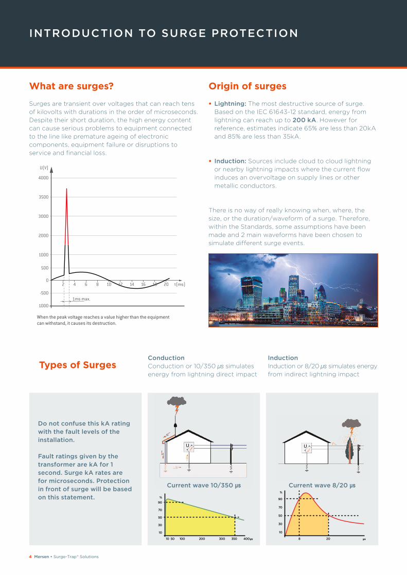
What are surges?
Surges are transient over voltages that can reach tens
of kilovolts with durations in the order of microseconds.
Despite their short duration, the high energy content
can cause serious problems to equipment connected
to the line like premature ageing of electronic
components, equipment failure or disruptions to
service and financial loss.
Origin of surges
• Lightning: The most destructive source of surge.
Based on the IEC 61643-12 standard, energy from
lightning can reach up to 200 kA. However for
reference, estimates indicate 65% are less than 20kA
and 85% are less than 35kA.
• Induction: Sources include cloud to cloud lightning
or nearby lightning impacts where the current flow
induces an overvoltage on supply lines or other
metallic conductors.
There is no way of really knowing when, where, the
size, or the duration/waveform of a surge. Therefore,
within the Standards, some assumptions have been
made and 2 main waveforms have been chosen to
simulate different surge events.
When the peak voltage reaches a value higher than the equipment can withstand, it causes its destruction.
1ms max.
U(V)
4000
3500
3000
2000
1000
500
-500
0
1000
2 4 6 8 10 12 14 16 18 20 t(ms)
Conduction Conduction or 10/350 μs simulates
energy from lightning direct impact
Induction Induction or 8/20 μs simulates energy
from indirect lightning impact
Do not confuse this kA rating with the fault levels of the installation.
Fault ratings given by the transformer are kA for 1 second. Surge kA rates are for microseconds. Protection in front of surge will be based on this statement.
Current wave 10/350 μs Current wave 8/20 μs
Types of Surges
835010
10
30
50
70
90
%
50 100 200 300 400 20
10
30
50
70
90
%
Mersen • Surge-Trap® Solutions 5
Internal sources: These are the main sources of surge in real life
They come from utility grid switching, disconnection of
motors or other inductive loads. Energy from these
sources is also analysed with the 8/20 μs wave form.
Transient overvoltages do not occur solely in power
distribution lines, they are also common in any line
formed by metal conductors, such as telephony,
communications, measurement and data.
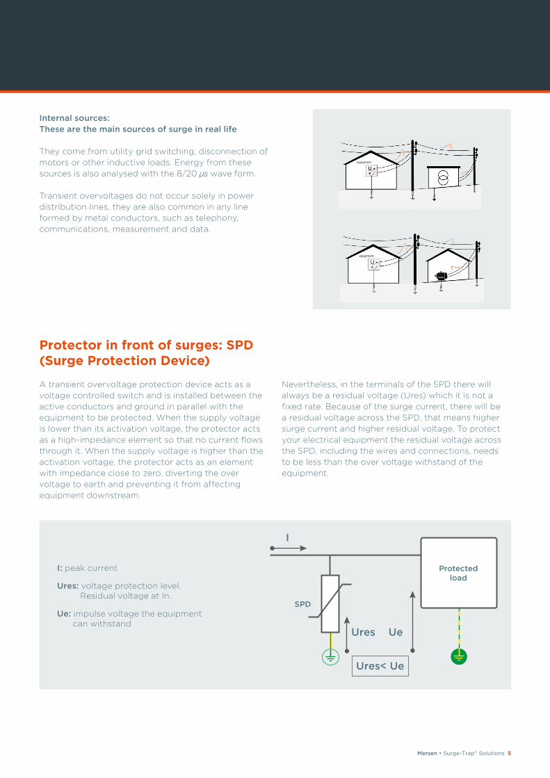
A transient overvoltage protection device acts as a
voltage controlled switch and is installed between the
active conductors and ground in parallel with the
equipment to be protected. When the supply voltage
is lower than its activation voltage, the protector acts
as a high-impedance element so that no current flows
through it. When the supply voltage is higher than the
activation voltage, the protector acts as an element
with impedance close to zero, diverting the over
voltage to earth and preventing it from affecting
equipment downstream.
Nevertheless, in the terminals of the SPD there will
always be a residual voltage (Ures) which it is not a
fixed rate. Because of the surge current, there will be
a residual voltage across the SPD, that means higher
surge current and higher residual voltage. To protect
your electrical equipment the residual voltage across
the SPD, including the wires and connections, needs
to be less than the over voltage withstand of the
equipment.
Ures< Ue
Ures Ue
I
Protected load
SPD
I: peak current
Ures: voltage protection level. Residual voltage at In.
Ue: impulse voltage the equipment can withstand
Protector in front of surges: SPD (Surge Protection Device)
equipment
equipment
6 Mersen • Surge-Trap® Solutions
SPD FEATURES BASED ON THE IEC 61643 STANDARD
Classification of protectors
Protection devices are classified into types according
to discharge capacity:
• Type 1: Tested with a 10/350 μs waveform (Class I test),
which simulates the current produced by a direct
lightning strike.
Ability to discharge very high currents to earth,
providing a high Up - voltage protection level.
Must be accompanied by downstream Type 2
protectors. Designed for use in incoming power
supply panels where the risk of lightning strike is
high, for example in buildings with an external
protection system.
• Type 2: Tested with a 8/20 μs waveform (Class II test), which
simulates the current produced in the event of a
switching or lightning strike on the distribution line
or its vicinity.
Ability to discharge high currents to earth, providing
a medium Up - voltage protection level. Designed for
use in distribution panels located downstream of
Type 1 protectors or in incoming power supply panels
in areas with low exposure to lightning strikes.
• Type 3: Tested with a combined 1.2/50 μs - 8/20 μs waveform
(Class III test), which simulates the current and
voltage that can reach the equipment to be protected.
Ability to discharge medium currents to earth,
providing a low Up - voltage protection level.
Always installed downstream of a Type 2 protection,
it is designed to protect sensitive equipment or
equipment located more than 20m downstream of
the Type 2 device.
The technology can provide protection solutions that
combine different types of protection: Type 1+2 and
Type 2+3.
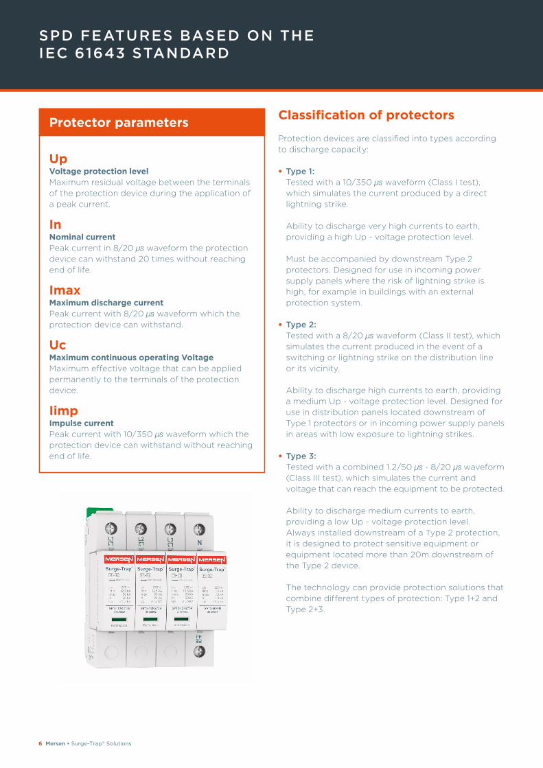
Protector parameters
Up Voltage protection level Maximum residual voltage between the terminals
of the protection device during the application of
a peak current.
In Nominal current Peak current in 8/20 μs waveform the protection
device can withstand 20 times without reaching
end of life.
Imax Maximum discharge current Peak current with 8/20 μs waveform which the
protection device can withstand.
Uc
Maximum continuous operating Voltage Maximum effective voltage that can be applied
permanently to the terminals of the protection
device.
Iimp Impulse current Peak current with 10/350 μs waveform which the
protection device can withstand without reaching
end of life.
Mersen • Surge-Trap® Solutions 7
Typical current (Ityp); SPD performance that guarantees the surge protection in the real life
Iimp, Imax and In show the one off maximum robustness
of the SPDs in heavy conditions. However, most surge
currents are in practice lower and repetitive because of
network switching or because of lightning inductions
onto the power grid.
The Typical Surge Current (Ityp) is the value that statistically
the SPD faces in real life. The value depends on the
level of exposure:
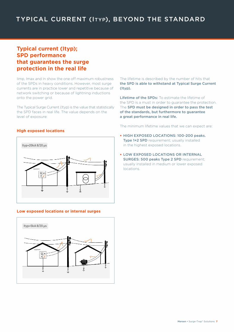
High exposed locations
Low exposed locations or internal surges
The lifetime is described by the number of hits that
the SPD is able to withstand at Typical Surge Current (Ityp).
Lifetime of the SPDs: To estimate the lifetime of
the SPD is a must in order to guarantee the protection.
The SPD must be designed in order to pass the test of the standards, but furthermore to guarantee a great performance in real life.
The minimum lifetime values that we can expect are:
• HIGH EXPOSED LOCATIONS: 100-200 peaks. Type 1+2 SPD requirement; usually installed
in the highest exposed locations.
• LOW EXPOSED LOCATIONS OR INTERNAL SURGES: 500 peaks Type 2 SPD requirement;
usually installed in medium or lower exposed
locations.
Ityp=20kA 8/20 μs
Ityp=5kA 8/20 μs
TYPICAL CURRENT (ITYP), BEYOND THE STANDARD
equipment
equipment
8 Mersen • Surge-Trap® Solutions
BS 7671:2018 / 18TH EDITION
A step ahead for surge protection
Posted 2nd July 2018 and effective from 1st January
2019, BS 7671 2018 supposes a big change for the
surge protection in the UK.
On one side, the 18th Edition opens the need for installing surge protection in a very broad spectrum from public, commercial or industrial activities too, even, consumer unit applications depending on the
circumstances. On a second side, the 18th Edition,
(based on the EN 62305-4 and EN 61643-12) describes
the selection and the application of surge protection
devices too.
Where is surge protection required?
Section 443. Protection against transient overvoltages of atmospheric origin or due to switching states that
protection against transient overvoltages shall be
provided where the consequence caused by overvoltage
could:
• Result in serious injury to, or loss of, human life, or
• Result in interruption of public services and/or damage to cultural heritage or,
• Result in interruption of commercial or industrial activity, or
• Affect a large number of co-located individuals.
For all other cases, a risk assessment according to
Regulation 443.5 shall be performed in order to
determine if protection against transient overvoltages
is required. If the risk assessment is not performed, the
electrical installation shall be provided with protection
against transient overvoltages, except for single
dwelling units where the total value of the installation
and equipment therein does not justify such
protection.
Protection against switching overvoltages shall be
considered in case of equipment likely to produce
switching overvoltages or disturbances exceeding the
values according to the overvoltage category of the
installation, e.g. where an LV generator supplies the
installation or where inductive or capacitive loads (e.g.
motors, transformers, capacitor banks), storage units
or high-current loads are installed.
Mersen • Surge-Trap® Solutions 9
Which SPD has to be selected?
Section 534 describes the selection and installation of SPD
Where to start the protection design?
At the origin of the installation, the main switchboard is
the place to start the design of SPDs on the network.
What is the SPD that has to be installed in the mains?
As stated in section 534.4 1.1, SPD installed at the
origin of the installation shall be Type 1 or Type 2.
Type 1, Type 2 which one has to be selected?
As previously stated, the SPD protection design does
not depend on the fault ratings given by the
transformer, it only depends on the level of exposure
in front of a surge. So, which SPD do we have to install
in the main switchboard?
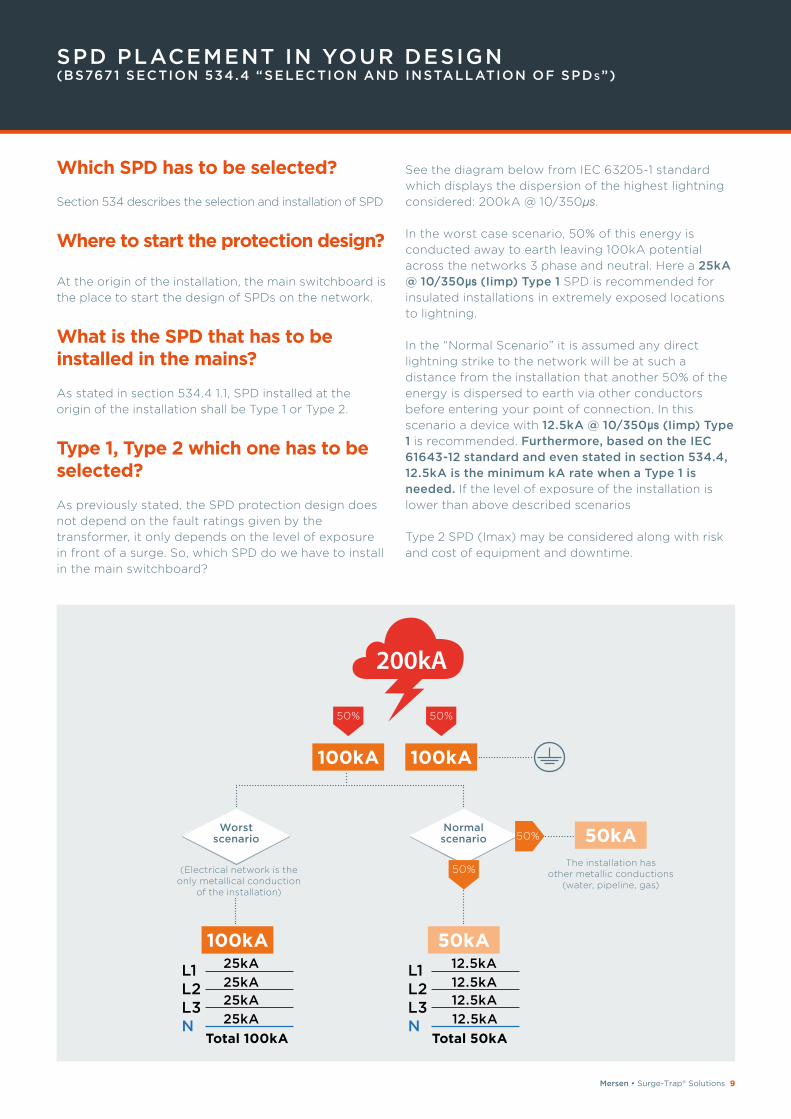
See the diagram below from IEC 63205-1 standard
which displays the dispersion of the highest lightning
considered: 200kA @ 10/350μs.
In the worst case scenario, 50% of this energy is
conducted away to earth leaving 100kA potential
across the networks 3 phase and neutral. Here a 25kA @ 10/350μs (Iimp) Type 1 SPD is recommended for
insulated installations in extremely exposed locations
to lightning.
In the “Normal Scenario” it is assumed any direct
lightning strike to the network will be at such a
distance from the installation that another 50% of the
energy is dispersed to earth via other conductors
before entering your point of connection. In this
scenario a device with 12.5kA @ 10/350μs (Iimp) Type 1 is recommended. Furthermore, based on the IEC 61643-12 standard and even stated in section 534.4, 12.5kA is the minimum kA rate when a Type 1 is needed. If the level of exposure of the installation is
lower than above described scenarios
Type 2 SPD (Imax) may be considered along with risk
and cost of equipment and downtime.
SPD PLACEMENT IN YOUR DESIGN(BS7671 SECTION 534.4 “SELECTION AND INSTALLATION OF SPDs”)
100kA 100kA
(Electrical network is the only metallical conduction
of the installation)
100kA
The installation has other metallic conductions
(water, pipeline, gas)
50kA
L1 L2 L3 N
Total 100kA
25kA
25kA25kA
25kA
L1 L2 L3 N
Total 50kA
12.5kA
12.5kA12.5kA
12.5kA
50%50%
Worst scenario
Normalscenario
50%
50% 50kA
10 Mersen • Surge-Trap® Solutions
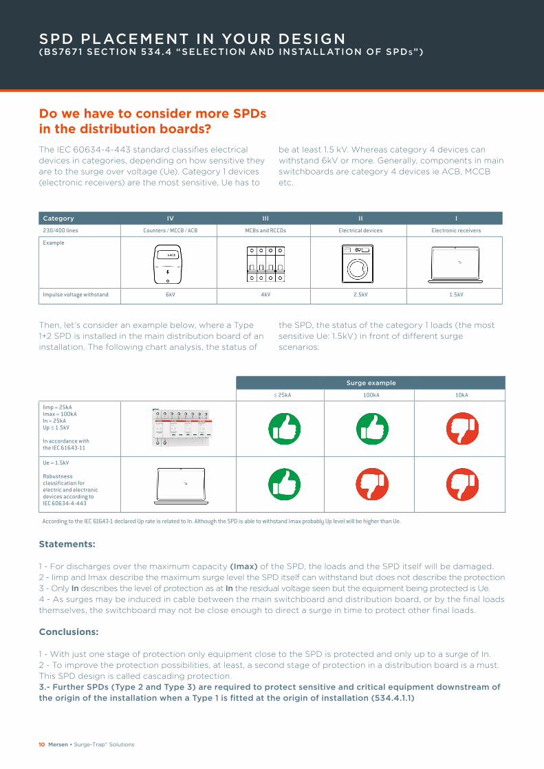
Surge example
≤ 25kA 100kA 10kA
limp = 25kAImax = 100kAIn = 25kAUp ≤ 1.5kV
In accordance withthe IEC 61643-11
Ue = 1.5kV
Robustnessclassification forelectric and electronicdevices according toIEC 60634-4-443
SPD PLACEMENT IN YOUR DESIGN(BS7671 SECTION 534.4 “SELECTION AND INSTALLATION OF SPDs”)
Category IV III II I
230/400 lines Counters / MCCB / ACB MCBs and RCCDs Electrical devices Electronic receivers
Example
Impulse voltage withstand 6kV 4kV 2.5kV 1.5kV
Statements:
1 - For discharges over the maximum capacity (Imax) of the SPD, the loads and the SPD itself will be damaged.
2 - Iimp and Imax describe the maximum surge level the SPD itself can withstand but does not describe the protection
3 - Only In describes the level of protection as at In the residual voltage seen but the equipment being protected is Ue.
4 - As surges may be induced in cable between the main switchboard and distribution board, or by the final loads
themselves, the switchboard may not be close enough to direct a surge in time to protect other final loads.
Conclusions:
1 - With just one stage of protection only equipment close to the SPD is protected and only up to a surge of In.
2 - To improve the protection possibilities, at least, a second stage of protection in a distribution board is a must.
This SPD design is called cascading protection.
3.- Further SPDs (Type 2 and Type 3) are required to protect sensitive and critical equipment downstream of the origin of the installation when a Type 1 is fitted at the origin of installation (534.4.1.1)
The IEC 60634-4-443 standard classifies electrical
devices in categories, depending on how sensitive they
are to the surge over voltage (Ue). Category 1 devices
(electronic receivers) are the most sensitive, Ue has to
be at least 1.5 kV. Whereas category 4 devices can
withstand 6kV or more. Generally, components in main
switchboards are category 4 devices ie ACB, MCCB
etc.
Then, let’s consider an example below, where a Type
1+2 SPD is installed in the main distribution board of an
installation. The following chart analysis, the status of
the SPD, the status of the category 1 loads (the most
sensitive Ue: 1.5kV) in front of different surge
scenarios:
According to the IEC 61643-1 declared Up rate is related to In. Although the SPD is able to withstand Imax probably Up level will be higher than Ue.
Do we have to consider more SPDs in the distribution boards?
Mersen • Surge-Trap® Solutions 11
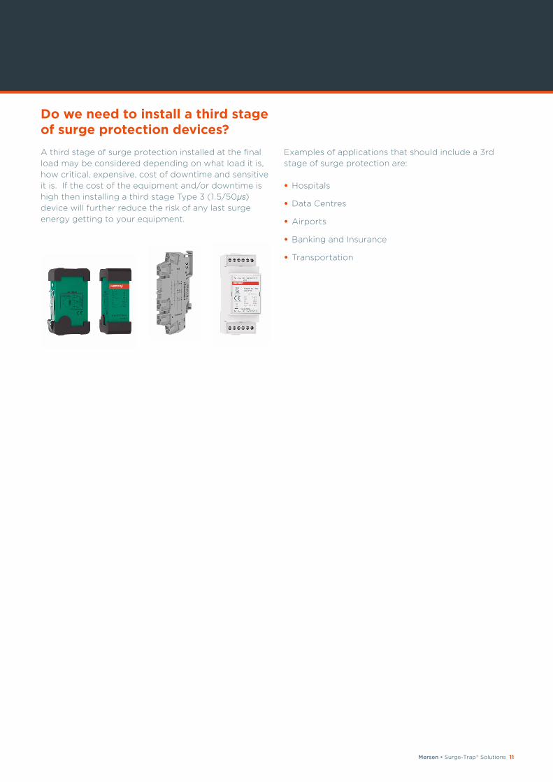
A third stage of surge protection installed at the final
load may be considered depending on what load it is,
how critical, expensive, cost of downtime and sensitive
it is. If the cost of the equipment and/or downtime is
high then installing a third stage Type 3 (1.5/50μs) device will further reduce the risk of any last surge
energy getting to your equipment.
Examples of applications that should include a 3rd
stage of surge protection are:
• Hospitals
• Data Centres
• Airports
• Banking and Insurance
• Transportation
Do we need to install a third stage of surge protection devices?
12 Mersen • Surge-Trap® Solutions
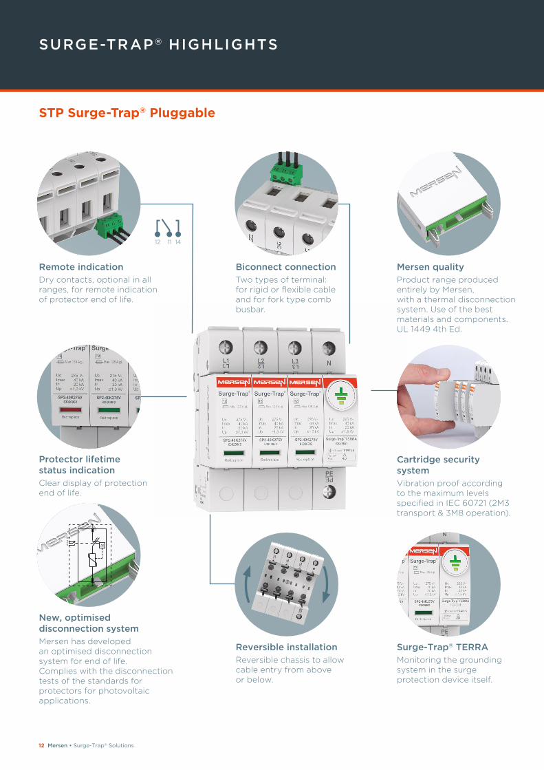
SURGE-TRAP® HIGHLIGHTS
t121114
Cartridge security systemVibration proof according to the maximum levels specified in IEC 60721 (2M3 transport & 3M8 operation).
Remote indicationDry contacts, optional in all ranges, for remote indication of protector end of life.
Biconnect connectionTwo types of terminal: for rigid or flexible cable and for fork type comb busbar.
Surge-Trap® TERRAMonitoring the grounding system in the surge protection device itself.
New, optimised disconnection system Mersen has developed an optimised disconnection system for end of life. Complies with the disconnection tests of the standards for protectors for photovoltaic applications.
Reversible installationReversible chassis to allow cable entry from above or below.
Mersen qualityProduct range produced entirely by Mersen, with a thermal disconnection system. Use of the best materials and components. UL 1449 4th Ed.
Protector lifetime status indicationClear display of protection end of life.
12 11 14
STP Surge-Trap® Pluggable
Mersen • Surge-Trap® Solutions 13
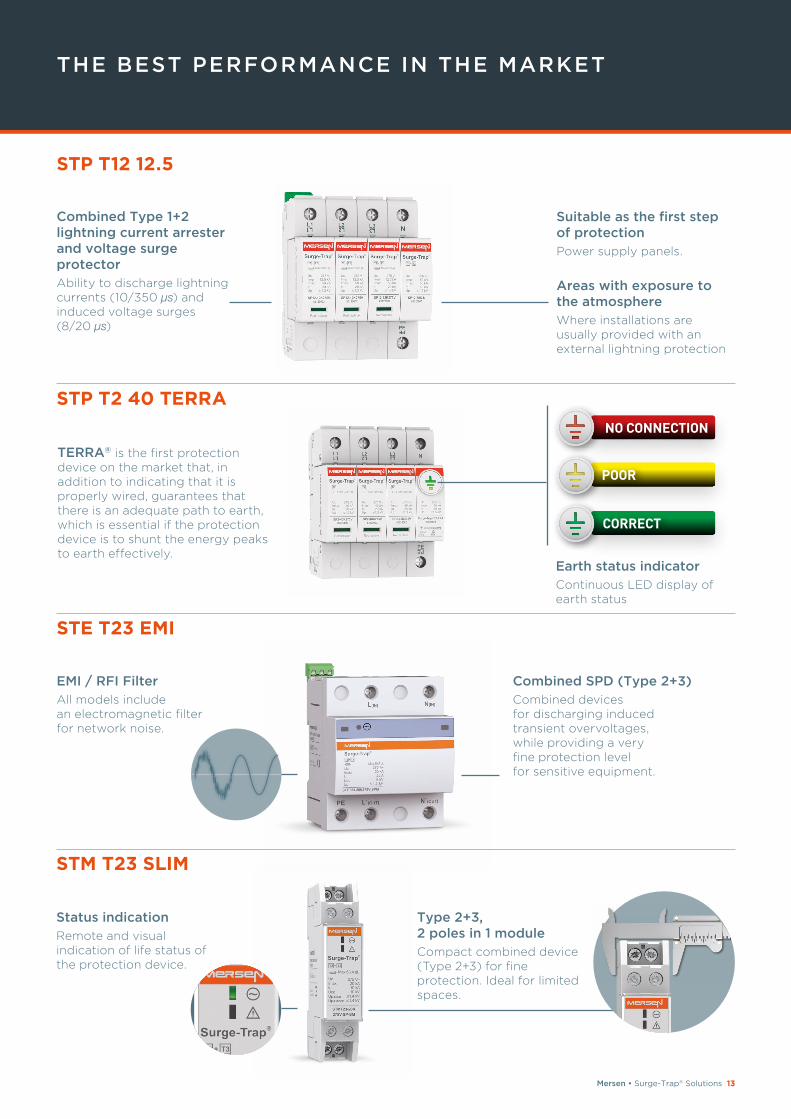
THE BEST PERFORMANCE IN THE MARKET
STP T12 12.5
STP T2 40 TERRA
STE T23 EMI
Suitable as the first step of protection Power supply panels.
Areas with exposure to the atmosphere Where installations are usually provided with an external lightning protection
Combined SPD (Type 2+3) Combined devices for discharging induced transient overvoltages, while providing a very fine protection level for sensitive equipment.
EMI / RFI FilterAll models include an electromagnetic filter for network noise.
STM T23 SLIM
Status indicationRemote and visual indication of life status of the protection device.
Type 2+3, 2 poles in 1 moduleCompact combined device (Type 2+3) for fine protection. Ideal for limited spaces.
Combined Type 1+2 lightning current arrester and voltage surge protectorAbility to discharge lightning currents (10/350 μs) and induced voltage surges (8/20 μs)
TERRA® is the first protection device on the market that, in addition to indicating that it is properly wired, guarantees that there is an adequate path to earth, which is essential if the protection device is to shunt the energy peaks to earth effectively.
POOR
NO CONNECTION
CORRECT
Earth status indicatorContinuous LED display of earth status
14 Mersen • Surge-Trap® Solutions
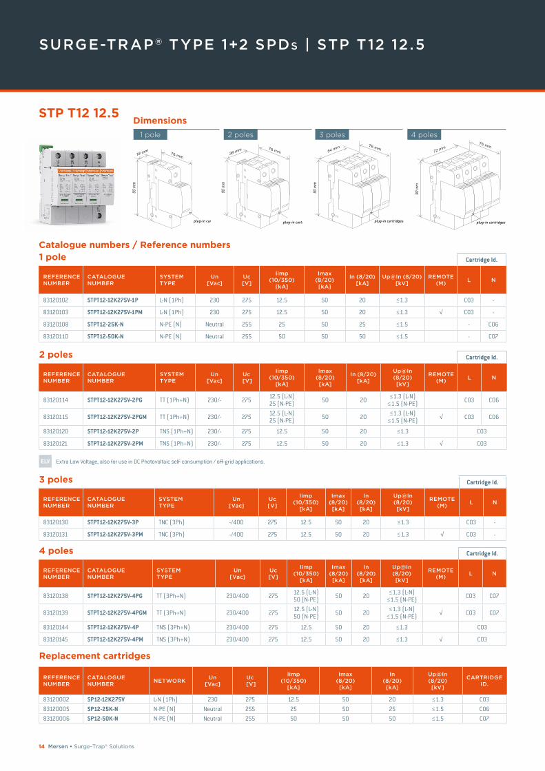
SURGE-TRAP® TYPE 1+2 SPDs | STP T12 12 .5
STP T12 12.5Dimensions
1 pole 2 poles 4 poles3 poles
1 pole Cartridge Id.
REFERENCE NUMBER
CATALOGUENUMBER
SYSTEM TYPE
Un [Vac]
Uc [V]
Iimp (10/350)
[kA]
Imax (8/20) [kA]
In (8/20) [kA]
Up@In (8/20) [kV]
REMOTE (M)
L N
83120102 STPT12-12K275V-1P L-N (1Ph) 230 275 12.5 50 20 ≤1.3 C03 -
83120103 STPT12-12K275V-1PM L-N (1Ph) 230 275 12.5 50 20 ≤1.3 √ C03 -
83120108 STPT12-25K-N N-PE (N) Neutral 255 25 50 25 ≤1.5 - C06
83120110 STPT12-50K-N N-PE (N) Neutral 255 50 50 50 ≤1.5 - C07
3 poles Cartridge Id.
REFERENCE NUMBER
CATALOGUENUMBER
SYSTEM TYPE
Un [Vac]
Uc [V]
Iimp (10/350)
[kA]
Imax (8/20) [kA]
In (8/20) [kA]
Up@In (8/20) [kV]
REMOTE (M)
L N
83120130 STPT12-12K275V-3P TNC (3Ph) -/400 275 12.5 50 20 ≤1.3 C03 -
83120131 STPT12-12K275V-3PM TNC (3Ph) -/400 275 12.5 50 20 ≤1.3 √ C03 -
4 poles Cartridge Id.
REFERENCE NUMBER
CATALOGUENUMBER
SYSTEM TYPE
Un [Vac]
Uc [V]
Iimp(10/350)
[kA]
Imax(8/20)[kA]
In (8/20) [kA]
Up@In(8/20)[kV]
REMOTE (M)
L N
83120138 STPT12-12K275V-4PG TT (3Ph+N) 230/400 275 12.5 (L-N) 50 (N-PE) 50 20 ≤1.3 (L-N)
≤1.5 (N-PE) C03 C07
83120139 STPT12-12K275V-4PGM TT (3Ph+N) 230/400 275 12.5 (L-N) 50 (N-PE) 50 20 ≤1.3 (L-N)
≤1.5 (N-PE) √ C03 C07
83120144 STPT12-12K275V-4P TNS (3Ph+N) 230/400 275 12.5 50 20 ≤1.3 C03
83120145 STPT12-12K275V-4PM TNS (3Ph+N) 230/400 275 12.5 50 20 ≤1.3 √ C03
Catalogue numbers / Reference numbers
2 poles Cartridge Id.
REFERENCE NUMBER
CATALOGUENUMBER
SYSTEM TYPE
Un [Vac]
Uc [V]
Iimp(10/350)
[kA]
Imax(8/20)[kA]
In (8/20) [kA]
Up@In(8/20)[kV]
REMOTE (M)
L N
83120114 STPT12-12K275V-2PG TT (1Ph+N) 230/- 275 12.5 (L-N) 25 (N-PE) 50 20 ≤1.3 (L-N)
≤1.5 (N-PE) C03 C06
83120115 STPT12-12K275V-2PGM TT (1Ph+N) 230/- 275 12.5 (L-N) 25 (N-PE) 50 20 ≤1.3 (L-N)
≤1.5 (N-PE) √ C03 C06
83120120 STPT12-12K275V-2P TNS (1Ph+N) 230/- 275 12.5 50 20 ≤1.3 C03
83120121 STPT12-12K275V-2PM TNS (1Ph+N) 230/- 275 12.5 50 20 ≤1.3 √ C03
ELV Extra Low Voltage, also for use in DC Photovoltaic self-consumption / off-grid applications.
REFERENCE NUMBER
CATALOGUE NUMBER
NETWORKUn
[Vac]Uc
[V]
Iimp (10/350)
[kA]
Imax (8/20)[kA]
In (8/20)[kA]
Up@In (8/20) [kV]
CARTRIDGE ID.
83120002 SP12-12K275V L-N (1Ph) 230 275 12.5 50 20 ≤1.3 C0383120005 SP12-25K-N N-PE (N) Neutral 255 25 50 25 ≤1.5 C0683120006 SP12-50K-N N-PE (N) Neutral 255 50 50 50 ≤1.5 C07
Replacement cartridges
Mersen • Surge-Trap® Solutions 15
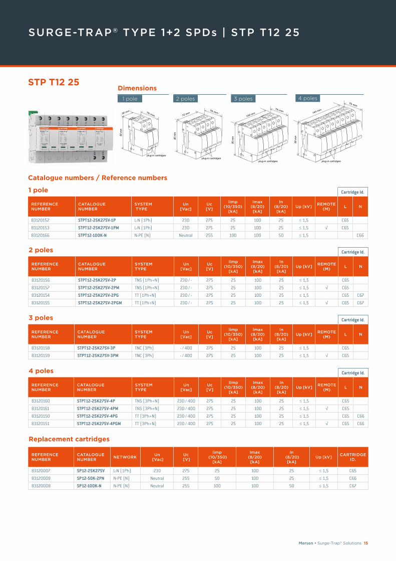
SURGE-TRAP® TYPE 1+2 SPDs | STP T12 25
36 mm
90 m
m
76 mm
plug-in cartridges
1 pole
72 mm
90 m
m
76 mm
plug-in cartridges
2 poles
108 mm
90 m
m
76 mm
plug-in cartridges
3 poles
144 mm
90 m
m
76 mm
plug-in cartridges
4 poles
STP T12 25Dimensions
Catalogue numbers / Reference numbers
1 pole Cartridge Id.
REFERENCE NUMBER
CATALOGUE NUMBER
SYSTEM TYPE
Un[Vac]
Uc [V]
Iimp(10/350)
[kA]
Imax(8/20)[kA]
In(8/20)[kA]
Up [kV]REMOTE
(M)L N
83120152 STPT12-25K275V-1P L-N (1Ph) 230 275 25 100 25 ≤ 1,5 C65
83120153 STPT12-25K275V-1PM L-N (1Ph) 230 275 25 100 25 ≤ 1,5 √ C65
83120166 STPT12-100K-N N-PE (N) Neutral 255 100 100 50 ≤ 1,5 C66
2 poles Cartridge Id.
REFERENCE NUMBER
CATALOGUE NUMBER
SYSTEM TYPE
Un[Vac]
Uc [V]
Iimp(10/350)
[kA]
Imax(8/20)[kA]
In(8/20)[kA]
Up [kV]REMOTE
(M)L N
83120156 STPT12-25K275V-2P TNS (1Ph+N) 230 / - 275 25 100 25 ≤ 1,5 C65
83120157 STPT12-25K275V-2PM TNS (1Ph+N) 230 / - 275 25 100 25 ≤ 1,5 √ C65
83120154 STPT12-25K275V-2PG TT (1Ph+N) 230 / - 275 25 100 25 ≤ 1,5 C65 C67
83120155 STPT12-25K275V-2PGM TT (1Ph+N) 230 / - 275 25 100 25 ≤ 1,5 √ C65 C67
3 poles Cartridge Id.
REFERENCE NUMBER
CATALOGUE NUMBER
SYSTEM TYPE
Un[Vac]
Uc [V]
Iimp(10/350)
[kA]
Imax(8/20)[kA]
In(8/20)[kA]
Up [kV]REMOTE
(M)L N
83120158 STPT12-25K275V-3P TNC (3Ph) - / 400 275 25 100 25 ≤ 1,5 C65
83120159 STPT12-25K275V-3PM TNC (3Ph) - / 400 275 25 100 25 ≤ 1,5 √ C65
4 poles Cartridge Id.
REFERENCE NUMBER
CATALOGUE NUMBER
SYSTEM TYPE
Un[Vac]
Uc [V]
Iimp(10/350)
[kA]
Imax(8/20)[kA]
In(8/20)[kA]
Up [kV]REMOTE
(M)L N
83120160 STPT12-25K275V-4P TNS (3Ph+N) 230 / 400 275 25 100 25 ≤ 1,5 C65
83120161 STPT12-25K275V-4PM TNS (3Ph+N) 230 / 400 275 25 100 25 ≤ 1,5 √ C65
83120150 STPT12-25K275V-4PG TT (3Ph+N) 230 / 400 275 25 100 25 ≤ 1,5 C65 C66
83120151 STPT12-25K275V-4PGM TT (3Ph+N) 230 / 400 275 25 100 25 ≤ 1,5 √ C65 C66
Replacement cartridges
REFERENCE NUMBER
CATALOGUE NUMBER
NETWORKUn
[Vac]Uc
[V]
Iimp (10/350)
[kA]
Imax (8/20)[kA]
In (8/20)
[kA]Up [kV]
CARTRIDGE ID.
83120007 SP12-25K275V L-N (1Ph) 230 275 25 100 25 ≤ 1,5 C65
83120009 SP12-50K-2PN N-PE (N) Neutral 255 50 100 25 ≤ 1,5 C66
83120008 SP12-100K-N N-PE (N) Neutral 255 100 100 50 ≤ 1,5 C67
16 Mersen • Surge-Trap® Solutions
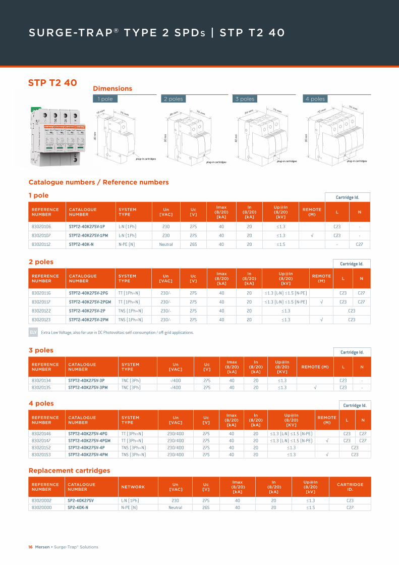
SURGE-TRAP® TYPE 2 SPDs | STP T2 40
Dimensions
1 pole 2 poles 3 poles 4 poles
Catalogue numbers / Reference numbers
1 pole Cartridge Id.
REFERENCE NUMBER
CATALOGUENUMBER
SYSTEM TYPE
Un [VAC]
Uc [V]
Imax (8/20) [kA]
In (8/20)[kA]
Up@In (8/20) [kV]
REMOTE (M)
L N
83020106 STPT2-40K275V-1P L-N (1Ph) 230 275 40 20 ≤1.3 C23 -
83020107 STPT2-40K275V-1PM L-N (1Ph) 230 275 40 20 ≤1.3 √ C23 -
83020112 STPT2-40K-N N-PE (N) Neutral 265 40 20 ≤1.5 - C27
2 poles Cartridge Id.
REFERENCE NUMBER
CATALOGUENUMBER
SYSTEM TYPE
Un [VAC]
Uc [V]
Imax (8/20) [kA]
In (8/20)[kA]
Up@In (8/20) [kV]
REMOTE (M)
L N
83020116 STPT2-40K275V-2PG TT (1Ph+N) 230/- 275 40 20 ≤1.3 (L-N) ≤1.5 (N-PE) C23 C27
83020117 STPT2-40K275V-2PGM TT (1Ph+N) 230/- 275 40 20 ≤1.3 (L-N) ≤1.5 (N-PE) √ C23 C27
83020122 STPT2-40K275V-2P TNS (1Ph+N) 230/- 275 40 20 ≤1.3 C23
83020123 STPT2-40K275V-2PM TNS (1Ph+N) 230/- 275 40 20 ≤1.3 √ C23
ELV Extra Low Voltage, also for use in DC Photovoltaic self-consumption / off-grid applications.
3 poles Cartridge Id.
REFERENCE NUMBER
CATALOGUENUMBER
SYSTEM TYPE
Un [VAC]
Uc [V]
Imax(8/20)[kA]
In(8/20)[kA]
Up@In(8/20)[KV]
REMOTE (M) L N
83020134 STPT2-40K275V-3P TNC (3Ph) -/400 275 40 20 ≤1.3 C23 -83020135 STPT2-40K275V-3PM TNC (3Ph) -/400 275 40 20 ≤1.3 √ C23 -
4 poles Cartridge Id.
REFERENCE NUMBER
CATALOGUENUMBER
SYSTEMTYPE
Un [VAC]
Uc [V]
Imax(8/20)[kA]
In(8/20)[kA]
Up@In(8/20)[KV]
REMOTE (M)
L N
83020146 STPT2-40K275V-4PG TT (3Ph+N) 230/400 275 40 20 ≤1.3 (L-N) ≤1.5 (N-PE) C23 C2783020147 STPT2-40K275V-4PGM TT (3Ph+N) 230/400 275 40 20 ≤1.3 (L-N) ≤1.5 (N-PE) √ C23 C2783020152 STPT2-40K275V-4P TNS (3Ph+N) 230/400 275 40 20 ≤1.3 C2383020153 STPT2-40K275V-4PM TNS (3Ph+N) 230/400 275 40 20 ≤1.3 √ C23
REFERENCE NUMBER
CATALOGUENUMBER
NETWORKUn
[VAC]Uc [V]
Imax (8/20)
[kA]
In (8/20)
[kA]
Up@In (8/20) [kV]
CARTRIDGEID.
83020002 SP2-40K275V L-N (1Ph) 230 275 40 20 ≤1.3 C2383020000 SP2-40K-N N-PE (N) Neutral 265 40 20 ≤1.5 C27
Replacement cartridges
STP T2 40
Mersen • Surge-Trap® Solutions 17
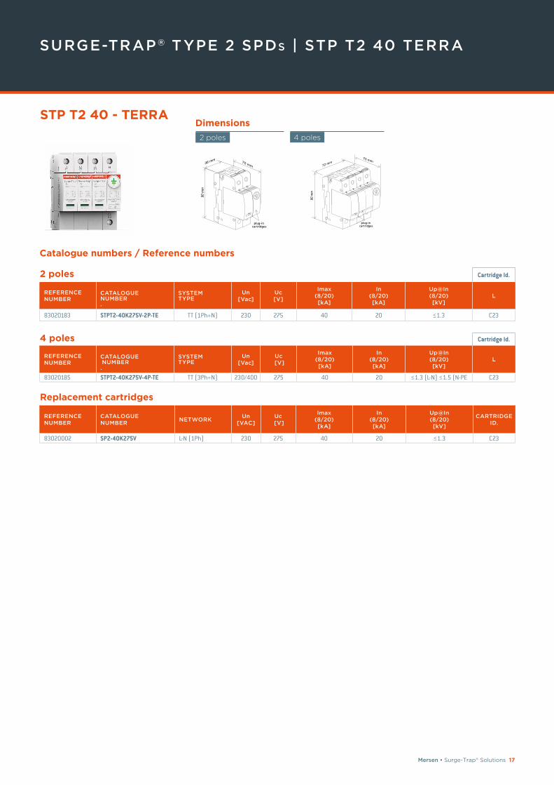
SURGE-TRAP® TYPE 2 SPDs | STP T2 40 TERRA
Dimensions
4 poles
Catalogue numbers / Reference numbers
REFERENCE NUMBER
CATALOGUENUMBER
NETWORKUn
[VAC]Uc
[V]
Imax (8/20) [kA]
In (8/20)[kA]
Up@In (8/20) [kV]
CARTRIDGEID.
83020002 SP2-40K275V L-N (1Ph) 230 275 40 20 ≤1.3 C23
Replacement cartridges
STP T2 40 - TERRA
36 mm
90 m
m
70 mm
plug-incartridges
plug-incartridges
2 poles
2 poles Cartridge Id.
REFERENCE NUMBER
CATALOGUE NUMBER .
SYSTEM TYPE
Un [Vac]
Uc [V]
Imax (8/20) [kA]
In (8/20) [kA]
Up@In (8/20) [kV]
L
83020183 STPT2-40K275V-2P-TE TT (1Ph+N) 230 275 40 20 ≤1.3 C23
4 poles Cartridge Id.
REFERENCE NUMBER
CATALOGUE NUMBER .
SYSTEMTYPE
Un [Vac]
Uc [V]
Imax (8/20) [kA]
In (8/20) [kA]
Up@In (8/20) [kV]
L
83020185 STPT2-40K275V-4P-TE TT (3Ph+N) 230/400 275 40 20 ≤1.3 (L-N) ≤1.5 (N-PE C23
18 Mersen • Surge-Trap® Solutions
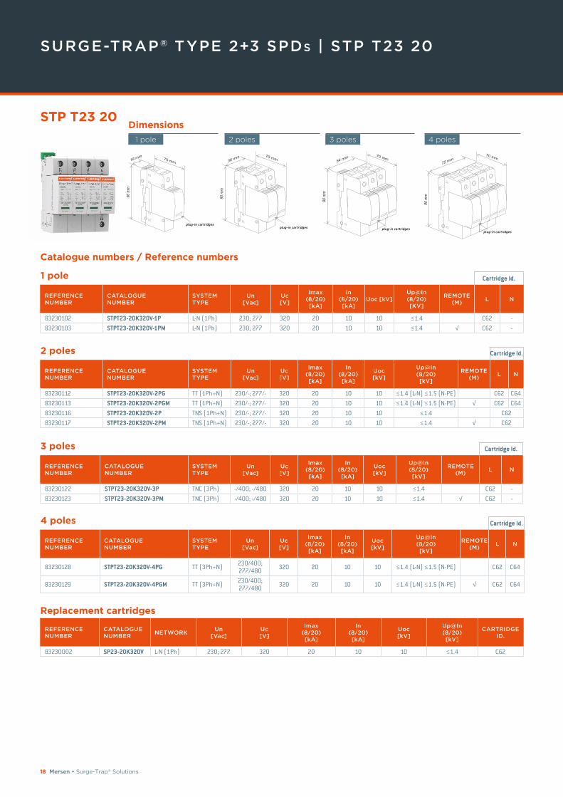
SURGE-TRAP® TYPE 2+3 SPDs | STP T23 20
STP T23 20
Catalogue numbers / Reference numbers
1 pole Cartridge Id.
REFERENCE NUMBER
CATALOGUENUMBER
SYSTEM TYPE
Un [Vac]
Uc[V]
Imax(8/20)[kA]
In(8/20)[kA]
Uoc [kV]Up@In(8/20)[KV]
REMOTE (M)
L N
83230102 STPT23-20K320V-1P L-N (1Ph) 230; 277 320 20 10 10 ≤1.4 C62 -83230103 STPT23-20K320V-1PM L-N (1Ph) 230; 277 320 20 10 10 ≤1.4 √ C62 -
2 poles Cartridge Id.
REFERENCE NUMBER
CATALOGUENUMBER
SYSTEM TYPE
Un [Vac]
Uc [V]
Imax(8/20)[kA]
In(8/20) [kA]
Uoc [kV]
Up@In(8/20)[kV]
REMOTE (M)
L N
83230112 STPT23-20K320V-2PG TT (1Ph+N) 230/-; 277/- 320 20 10 10 ≤1.4 (L-N) ≤1.5 (N-PE) C62 C6483230113 STPT23-20K320V-2PGM TT (1Ph+N) 230/-; 277/- 320 20 10 10 ≤1.4 (L-N) ≤1.5 (N-PE) √ C62 C6483230116 STPT23-20K320V-2P TNS (1Ph+N) 230/-; 277/- 320 20 10 10 ≤1.4 C6283230117 STPT23-20K320V-2PM TNS (1Ph+N) 230/-; 277/- 320 20 10 10 ≤1.4 √ C62
3 poles Cartridge Id.
REFERENCE NUMBER
CATALOGUENUMBER
SYSTEM TYPE
Un [Vac]
Uc[V]
Imax(8/20)[kA]
In(8/20) [kA]
Uoc [kV]
Up@In (8/20) [kV]
REMOTE (M)
L N
83230122 STPT23-20K320V-3P TNC (3Ph) -/400; -/480 320 20 10 10 ≤1.4 C62 -83230123 STPT23-20K320V-3PM TNC (3Ph) -/400; -/480 320 20 10 10 ≤1.4 √ C62 -
4 poles Cartridge Id.
REFERENCE NUMBER
CATALOGUENUMBER
SYSTEM TYPE
Un [Vac]
Uc [V]
Imax(8/20)[kA]
In(8/20) [kA]
Uoc [kV]
Up@In(8/20)[kV]
REMOTE (M)
L N
83230128 STPT23-20K320V-4PG TT (3Ph+N) 230/400; 277/480 320 20 10 10 ≤1.4 (L-N) ≤1.5 (N-PE) C62 C64
83230129 STPT23-20K320V-4PGM TT (3Ph+N) 230/400; 277/480 320 20 10 10 ≤1.4 (L-N) ≤1.5 (N-PE) √ C62 C64
REFERENCE NUMBER
CATALOGUENUMBER
NETWORKUn
[Vac]Uc [V]
Imax (8/20) [kA]
In (8/20)[kA]
Uoc[kV]
Up@In (8/20) [kV]
CARTRIDGE ID.
83230002 SP23-20K320V L-N (1Ph) 230; 277 320 20 10 10 ≤1.4 C62
Replacement cartridges
Dimensions
1 pole 2 poles 3 poles 4 poles
Mersen • Surge-Trap® Solutions 19
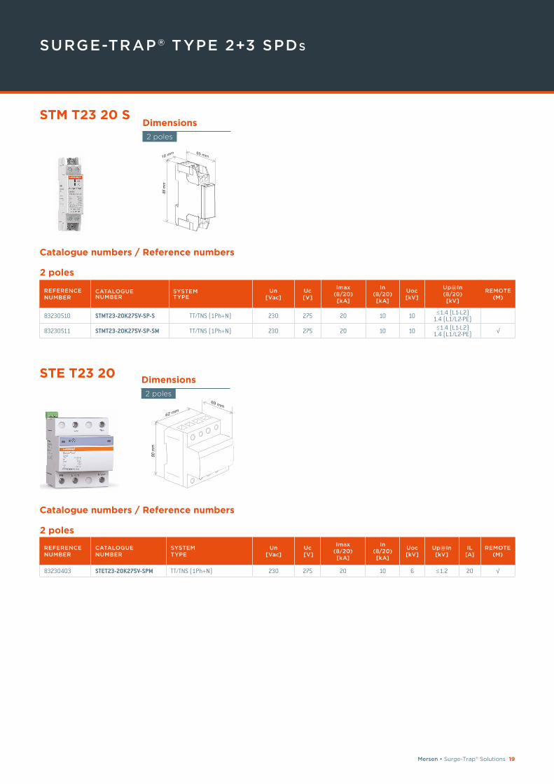
SURGE-TRAP® TYPE 2+3 SPDs
Catalogue numbers / Reference numbers
2 poles
REFERENCE NUMBER
CATALOGUE NUMBER
SYSTEM TYPE
Un [Vac]
Uc [V]
Imax(8/20) [kA]
In(8/20) [kA]
Uoc [kV]
Up@In (8/20)[kV]
REMOTE(M)
83230510 STMT23-20K275V-SP-S TT/TNS (1Ph+N) 230 275 20 10 10 ≤1.4 (L1-L2) 1.4 (L1/L2-PE)
83230511 STMT23-20K275V-SP-SM TT/TNS (1Ph+N) 230 275 20 10 10 ≤1.4 (L1-L2) 1.4 (L1/L2-PE) √
2 poles
REFERENCE NUMBER
CATALOGUENUMBER
SYSTEMTYPE
Un [Vac]
Uc [V]
Imax (8/20) [kA]
In (8/20)[kA]
Uoc [kV]
Up@In [kV]
IL [A]
REMOTE(M)
83230403 STET23-20K275V-SPM TT/TNS (1Ph+N) 230 275 20 10 6 ≤1.2 20 √
Dimensions
2 poles
STM T23 20 S
Catalogue numbers / Reference numbers
Dimensions
2 poles
STE T23 20
20 Mersen • Surge-Trap® Solutions
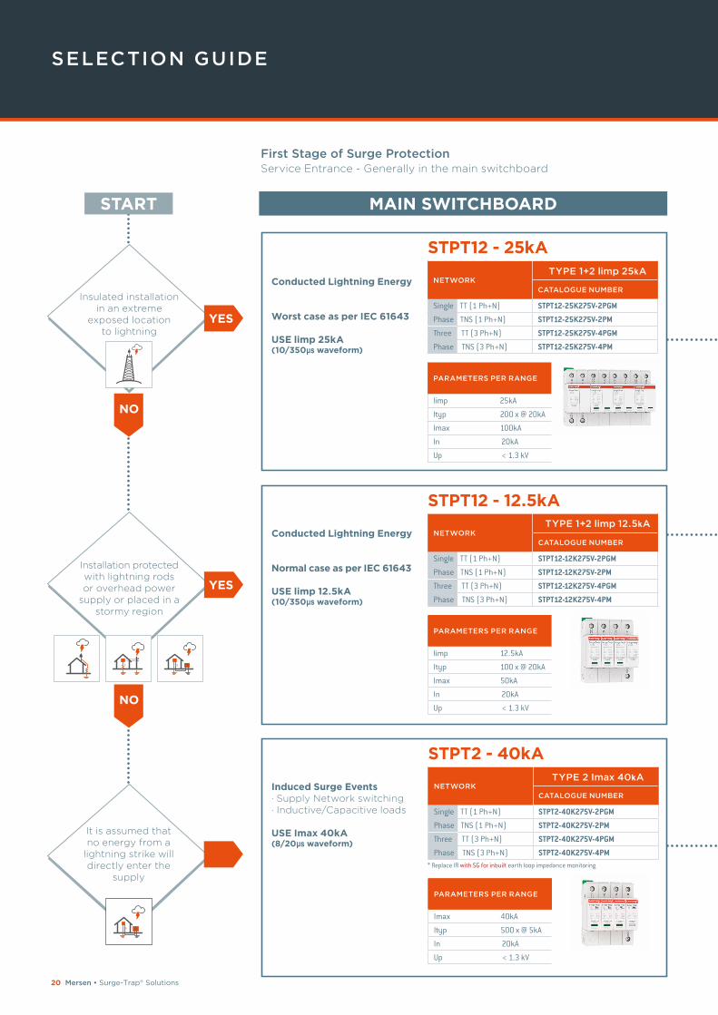
SELECTION GUIDE
Insulated installation in an extreme
exposed location to lightning
MAIN SWITCHBOARD
STPT12 - 25kA
Conducted Lightning Energy
Worst case as per IEC 61643
USE limp 25kA (10/350μs waveform)
NETWORK CATALOGUE NUMBER
Single TT (1 Ph+N) STPT12-25K275V-2PGM
Phase TNS (1 Ph+N) STPT12-25K275V-2PM
Three TT (3 Ph+N) STPT12-25K275V-4PGM
Phase TNS (3 Ph+N) STPT12-25K275V-4PM
PARAMETERS PER RANGE
limp 25kA
Ityp 200 x @ 20kA
Imax 100kA
In 20kA
Up < 1.3 kV
NO
Installation protected with lightning rods or overhead power
supply or placed in a stormy region
TYPE 1+2 limp 25kA
STPT12 - 12.5kA
Conducted Lightning Energy
Normal case as per IEC 61643
USE limp 12.5kA(10/350μs waveform)
PARAMETERS PER RANGE
limp 12.5kA
Ityp 100 x @ 20kA
Imax 50kA
In 20kA
Up < 1.3 kV
It is assumed that no energy from a
lightning strike will directly enter the
supply
NO
STPT2 - 40kA
Induced Surge Events· Supply Network switching· Inductive/Capacitive loads
USE Imax 40kA(8/20μs waveform)
PARAMETERS PER RANGE
Imax 40kA
Ityp 500 x @ 5kA
In 20kA
Up < 1.3 kV
* Replace IR with SG for inbuilt earth loop impedance monitoring
First Stage of Surge Protection Service Entrance - Generally in the main switchboard
START
YES
YES
NETWORK CATALOGUE NUMBER
Single TT (1 Ph+N) STPT12-12K275V-2PGM
Phase TNS (1 Ph+N) STPT12-12K275V-2PM
Three TT (3 Ph+N) STPT12-12K275V-4PGM
Phase TNS (3 Ph+N) STPT12-12K275V-4PM
TYPE 1+2 limp 12.5kA
NETWORK CATALOGUE NUMBER
Single TT (1 Ph+N) STPT2-40K275V-2PGM
Phase TNS (1 Ph+N) STPT2-40K275V-2PM
Three TT (3 Ph+N) STPT2-40K275V-4PGM
Phase TNS (3 Ph+N) STPT2-40K275V-4PM
TYPE 2 Imax 40kA
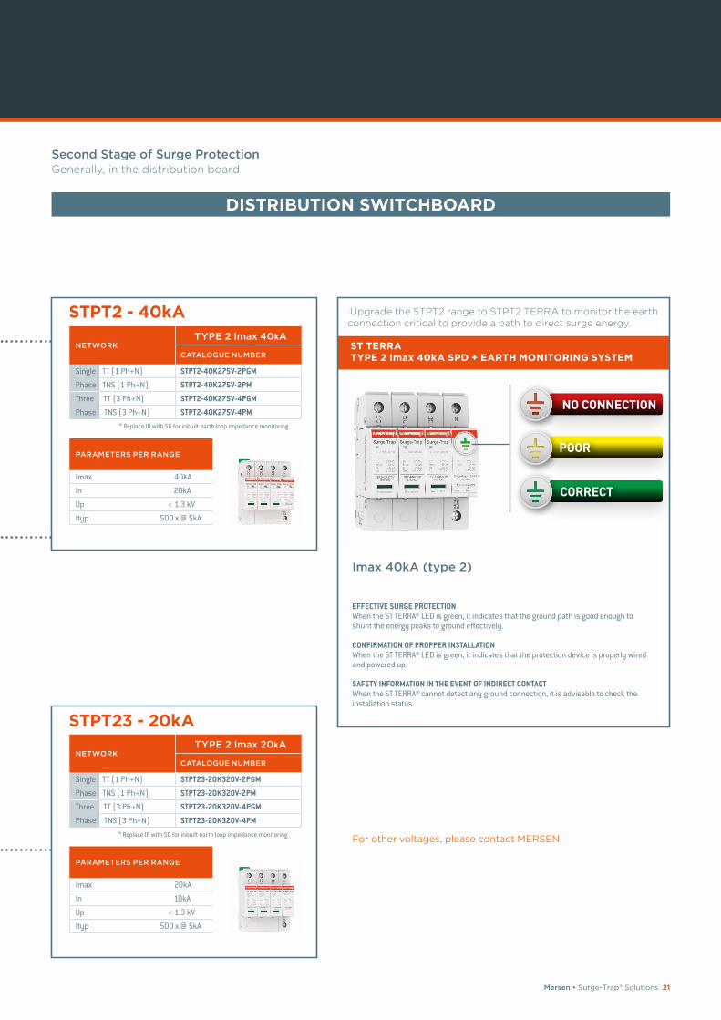
Mersen • Surge-Trap® Solutions 21
STPT2 - 40kA
PARAMETERS PER RANGE
Imax 40kA
In 20kA
Up < 1.3 kV
Ityp 500 x @ 5kA
STPT23 - 20kA
PARAMETERS PER RANGE
Imax 20kA
In 10kA
Up < 1.3 kV
Ityp 500 x @ 5kA
* Replace IR with SG for inbuilt earth loop impedance monitoring
* Replace IR with SG for inbuilt earth loop impedance monitoringFor other voltages, please contact MERSEN.
·Upgrade the STPT2 range to STPT2 TERRA to monitor the earth connection critical to provide a path to direct surge energy.
ST TERRA TYPE 2 Imax 40kA SPD + EARTH MONITORING SYSTEM
Imax 40kA (type 2)
EFFECTIVE SURGE PROTECTION When the ST TERRA® LED is green, it indicates that the ground path is good enough to shunt the energy peaks to ground effectively.
CONFIRMATION OF PROPPER INSTALLATION When the ST TERRA® LED is green, it indicates that the protection device is properly wired and powered up.
SAFETY INFORMATION IN THE EVENT OF INDIRECT CONTACT When the ST TERRA® cannot detect any ground connection, it is advisable to check the installation status.
POOR
NO CONNECTION
CORRECT
Second Stage of Surge Protection Generally, in the distribution board
DISTRIBUTION SWITCHBOARD
NETWORK CATALOGUE NUMBER
Single TT (1 Ph+N) STPT2-40K275V-2PGM
Phase TNS (1 Ph+N) STPT2-40K275V-2PM
Three TT (3 Ph+N) STPT2-40K275V-4PGM
Phase TNS (3 Ph+N) STPT2-40K275V-4PM
TYPE 2 Imax 40kA
NETWORK CATALOGUE NUMBER
Single TT (1 Ph+N) STPT23-20K320V-2PGM
Phase TNS (1 Ph+N) STPT23-20K320V-2PM
Three TT (3 Ph+N) STPT23-20K320V-4PGM
Phase TNS (3 Ph+N) STPT23-20K320V-4PM
TYPE 2 Imax 20kA
22 Mersen • Surge-Trap® Solutions
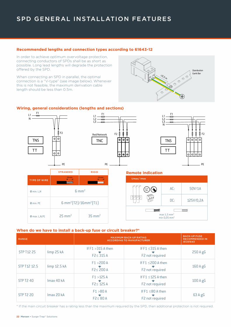
SPD GENERAL INSTALLATION FEATURES
TNS
F2
F1
PE
L1L2L3N
TNS
F2
F1
PE
L1N
TNC
Red/Network F2
F1
PE
L1L2L3
In order to achieve optimum overvoltage protection, connecting conductors of SPDs shall be as short as possible. Long lead lengths will degrade the protection offered by the SPD.
When connecting an SPD in parallel, the optimal connection is a “V-type” (see image below). Whenever this is not feasible, the maximum derivation cable length should be less than 0.5m.
STRANDED RIGID
TYPE OF WIRE
ø min. L,N 6 mm2
ø min. PE 6 mm2(T2)/16mm2(T1)
ø max. L,N,PE 25 mm2 35 mm2
10 mm 10 mm
Remote IndicationUmax/ Imax
* If the main circuit breaker has a rating less than the maximum required by the SPD, then additional protection is not required.
Wiring, general considerations (lengths and sections)
RANGE MAXIMUM BACK-UP RATING
ACCORDING TO MANUFACTURER
BACK-UP FUSE RECOMMENDED IN IEC61643
STP T12 25 limp 25 kAIf F1 >315 A then
F2≤ 315 A
If F1 ≤315 A then
F2 not required250 A gG
STP T12 12.5 limp 12.5 kAF1 >200 A
F2≤ 200 A
If F1 ≤200 A then
F2 not required160 A gG
STP T2 40 Imax 40 kAF1 >125 A
F2≤ 125 A
If F1 ≤125 A then
F2 not required100 A gG
STP T2 20 Imax 20 kAF1 >80 A
F2≤ 80 A
If F1 ≤80 A then
F2 not required63 A gG
When do we have to install a back-up fuse or circuit breaker?*
Recommended lengths and connection types according to 61643-12
AC:
DC: 125V/0,2A
50V/1A
max 1,5 mm2
min 0,05 mm2
0,27Nm
12 11 14
Mersen • Surge-Trap® Solutions 23
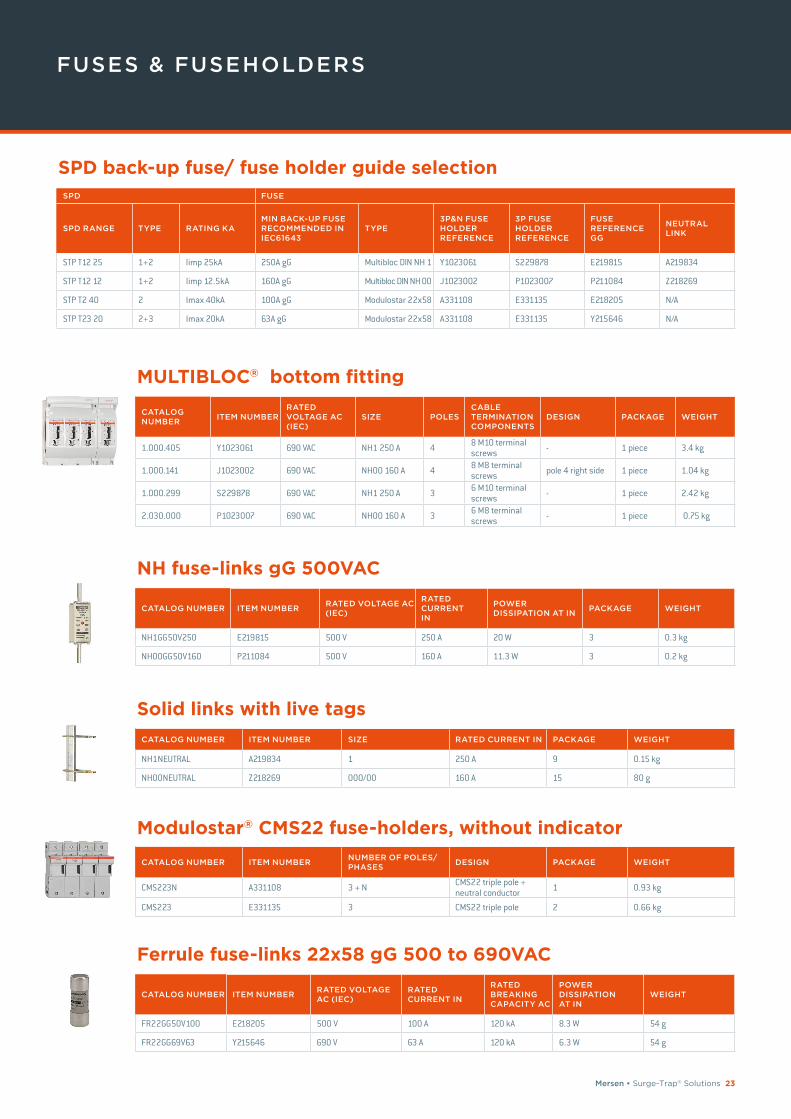
FUSES & FUSEHOLDERS
SPD FUSE
SPD RANGE TYPE RATING KAMIN BACK-UP FUSE RECOMMENDED IN IEC61643
TYPE3P&N FUSE HOLDER REFERENCE
3P FUSE HOLDER REFERENCE
FUSE REFERENCE GG
NEUTRAL LINK
STP T12 25 1+2 Iimp 25kA 250A gG Multibloc DIN NH 1 Y1023061 S229878 E219815 A219834
STP T12 12 1+2 Iimp 12.5kA 160A gG Multibloc DIN NH 00 J1023002 P1023007 P211084 Z218269
STP T2 40 2 Imax 40kA 100A gG Modulostar 22x58 A331108 E331135 E218205 N/A
STP T23 20 2+3 Imax 20kA 63A gG Modulostar 22x58 A331108 E331135 Y215646 N/A
CATALOG NUMBER
ITEM NUMBERRATED VOLTAGE AC (IEC)
SIZE POLESCABLE TERMINATION COMPONENTS
DESIGN PACKAGE WEIGHT
1.000.405 Y1023061 690 VAC NH1 250 A 4 8 M10 terminal screws - 1 piece 3.4 kg
1.000.141 J1023002 690 VAC NH00 160 A 4 8 M8 terminal screws pole 4 right side 1 piece 1.04 kg
1.000.299 S229878 690 VAC NH1 250 A 3 6 M10 terminal screws - 1 piece 2.42 kg
2.030.000 P1023007 690 VAC NH00 160 A 3 6 M8 terminal screws - 1 piece 0.75 kg
CATALOG NUMBER ITEM NUMBERRATED VOLTAGE AC (IEC)
RATED CURRENT IN
POWER DISSIPATION AT IN
PACKAGE WEIGHT
NH1GG50V250 E219815 500 V 250 A 20 W 3 0.3 kg
NH00GG50V160 P211084 500 V 160 A 11.3 W 3 0.2 kg
CATALOG NUMBER ITEM NUMBER SIZE RATED CURRENT IN PACKAGE WEIGHT
NH1NEUTRAL A219834 1 250 A 9 0.15 kg
NH00NEUTRAL Z218269 000/00 160 A 15 80 g
CATALOG NUMBER ITEM NUMBERNUMBER OF POLES/PHASES
DESIGN PACKAGE WEIGHT
CMS223N A331108 3 + N CMS22 triple pole + neutral conductor 1 0.93 kg
CMS223 E331135 3 CMS22 triple pole 2 0.66 kg
CATALOG NUMBER ITEM NUMBERRATED VOLTAGE AC (IEC)
RATED CURRENT IN
RATED BREAKING CAPACITY AC
POWER DISSIPATION AT IN
WEIGHT
FR22GG50V100 E218205 500 V 100 A 120 kA 8.3 W 54 g
FR22GG69V63 Y215646 690 V 63 A 120 kA 6.3 W 54 g
SPD back-up fuse/ fuse holder guide selection
MULTIBLOC® bottom fitting
NH fuse-links gG 500VAC
Solid links with live tags
Modulostar® CMS22 fuse-holders, without indicator
Ferrule fuse-links 22x58 gG 500 to 690VAC
G LO BA L E X P E RT
I N E L EC T R I C A L P OW E R
A N D A DVA N C E D M AT E R I A L S
EUROPE
UK MERSEN UK Unit 12, Tungsten Building, George Street-Portslade, East Sussex BN41 1RA + 44 (0)1273 425119 [email protected]
E P . M E R S E N . C O M
Me
rse
n p
rop
ert
y -
BR
-SU
RG
ET
RA
P-0
04
-111
9-
8941
- 1
1-20
19 -


![· [BS 7671, Table 4B1] [BS 7671, Table 4C4] of circuits per tray = 2 = 0.00 162.0 200 119.0 151.0 Ch = 1.00 rrent i Capacity N/A sized or ih ca bCi a vota](https://img.pdfslide.net/doc/110x75/5adf92e07f8b9af05b8c93db/bs-7671-table-4b1-bs-7671-table-4c4-of-circuits-per-tray-2-000-1620-200.jpg)
![BS 7671:2008+A3:2015 MODEL FORMS - … · electrical installation certificate (requirements for electrical installations - bs 7671 [ietw iring regulations]) details of the client](https://img.pdfslide.net/doc/110x75/5adc43097f8b9a4a268bdefc/bs-76712008a32015-model-forms-installation-certificate-requirements-for.jpg)