Embed Size (px)
DESCRIPTION
heat
Citation preview
A MODELICA-BASED MODEL LIBRARY FOR BUILDING ENERGY ANDCONTROL SYSTEMS
Michael WetterSimulation Research Group, Building Technologies Department
Environmental Energy Technologies Division, Lawrence Berkeley National LaboratoryBerkeley, CA 94720, USA
ABSTRACTThis paper describes an open-source library with
component models for building energy and controlsystems that is based on Modelica, an equation-basedobject-oriented language that is well positioned tobecome the standard for modeling of dynamic sys-tems in various industrial sectors. The library is cur-rently developed to support computational scienceand engineering for innovative building energy andcontrol systems. Early applications will include con-trols design and analysis, rapid prototyping to sup-port innovation of new building systems and the useof models during operation for controls, fault detec-tion and diagnostics.
This paper discusses the motivation for select-ing an equation-based object-oriented language. Itpresents the architecture of the library and explainshow base models can be used to rapidly implementnew models. To demonstrate the capability of ana-lyzing novel energy and control systems, the papercloses with an example where we compare the dy-namic performance of a conventional hydronic heat-ing system with thermostatic radiator valves to an in-novative heating system. In the new system, insteadof a centralized circulation pump, each of the 18 ra-diators has a pump whose speed is controlled usinga room temperature feedback loop, and the tempera-ture of the boiler is controlled based on the speed ofthe radiator pump. All flows are computed by solvingfor the pressure distribution in the piping network,and the controls include continuous and discrete timecontrols.
INTRODUCTIONTo significantly reduce greenhouse gas emissions
associated with building operations, developmentof building simulation programs along two paralleltracks is needed: First, the usability of existing build-ing simulation programs needs to be improved so thatthey can better support the design of efficient build-ings on a large scale. Second, to accelerate the inno-vation of new HVAC components, systems and con-trol algorithms, a modeling and simulation frame-
work needs to be developed that better meets thefunctional requirements of such applications. Thispaper deals with the second development. Typicalfunctional requirements include:
1. Faster implementation of models for equipment,systems and control algorithms, at different levelsof abstraction.
2. Means for implementing models by tool users inaddition to tool developers.
3. Ability to share models among users.4. Ability to model continuous time dynamics (for
physical processes), discrete time systems (for dis-crete time controls) and state events (such as forswitching controls).
5. Extraction of subsystem models for use in isola-tion from the total system model (such as for vali-dation, for more refined analysis, for model reduc-tion, or for use in operation).
6. Use of simulation models in conjunction with non-linear programming algorithms that require thecost function (such as energy use) to have littlenumerical noise. This is important to efficientlysolve optimal control problems that may involvestate trajectory constraints and hundreds of inde-pendent parameters that define the control func-tion.
From these functional requirements result severalcharacteristic features of the software architecturethat such a modeling and simulation environmentshould have. They include:
1. Object-oriented modeling to facilitate code reuse.2. Use of an equation-based language to allow more
natural modeling.3. Use of a standardized modeling language.4. Support for interfacing computational models with
real experimental facilities at the component andwhole building level.
5. Support for hierarchical model composition to al-low managing the complexity of large systems.
6. Use of a model connectivity framework that allowsa model builder to assemble models in a similar
Eleventh International IBPSA Conference Glasgow, Scotland
July 27-30, 2009
- 652 -

way to what an experimenter would do on a work-bench (cf. theobject-oriented modeling paradigmsummarized in Cellier 1996).
7. Use of symbolic algebra tools to reduce the dimen-sionality of the coupled systems of equations thatneed to be solved for simultaneously.
8. Use of numerical solvers that can solve stiff dif-ferential equation systems (which require implicitsolvers with adaptive step size, cf. Hairer andWanner 1996) that may contain boolean variables.
This list illustrates that such a computational envi-ronment needs tosimultaneouslysatisfy new require-ments with regard to graphical modeling environ-ments, modeling language, symbolic and numericalmethods, and code translators (that convert a modeldescription into an executable program). It is notlikely that these requirements can be met by an in-cremental evolution of an existing building simula-tion program, which typically contains hundreds ofthousands of lines of procedural code that mix pro-gram statements describing the physics with programstatements for control algorithms, data managementand numerical solution methods. Such program codedoes not allow use of code generators that use sym-bolic algebra for reducing the dimensionality of thecoupled equation systems, for automatic differentia-tion and for index reduction of differential algebraicequations. It also makes it impractical to use mod-ern solvers that analyze equation systems for eventsand differentiability. Both measures are used in mod-ern system simulation programs to increase compu-tational efficiency and robustness. To realize a mod-eling and simulation environment that can meet theabove needs, we believe it is most efficient to startwith a new approach that builds on the latest ad-vances in system modeling and simulation. How-ever, such a new environment for modeling and sim-ulation can still be used in conjunction with existingbuilding simulation programs using co-simulation,for example using the Building Controls Virtual TestBed (Wetter and Haves 2008).
Clearly, the development of such a computationalenvironment requires expertise from various researchdisciplines such as computer science (for languagedesign and code generation), mathematics (for sym-bolic and numerical methods) and engineering (forcreating modeling libraries). Hence, a tool for suchsystems should not be developed by the building sim-ulation community in isolation, but rather togetherwith other industrial sectors to share resources. Thisis the approach that is followed by the Modelicaconsortium which has been developing the Model-ica modeling language since 1997. Modelica is anequation-based, object-oriented language for model-
ing of systems that are described by algebraic equa-tions, differential equations, and difference equa-tions, and that may contain real variables, inte-gers, boolean variables and strings (Mattsson andElmqvist 1997).
Models written in the Modelica language cannotbe executed directly. Rather, a simulation environ-ment translates a Modelica model into an executableprogram. Several commercial and freely availablemodeling and simulation environments for Model-ica that support textual and graphical modeling exist.IDA ICE 4.0, to be released in spring 2009, appearsto be the first building simulation program that willsupport Modelica.1 For a list of Modelica model-ing and simulation environments, seehttp://www.modelica.org/tools. While the performance andprice of the different tools vary, there has been signif-icant progress in the development of these tools overthe last few years, and significant investments havebeen made in Modelica. For example, in three Euro-pean ITEA projects (EUROSYSLIB, MODELISARand OPENPROD), about 54 Million Euros for 370person years are invested to further develop Model-ica, Modelica tools, Modelica libraries and relatedtechnology.2
However, what is missing in Modelica is a com-prehensive library for building energy and controlsystems. Thus, LBNL started an open-source devel-opment effort with the aim of filling this gap. Whilethe library is currently used within LBNL projects,it is our intention to broaden the development ef-fort and collaborate with other developers to cre-ate an open-source Modelica library that meets theneed for simulation-based innovation in building sys-tems. This paper presents the current design of the li-brary, which is available free of charge, including itssource code, fromhttp://simulationresearch.lbl.gov.
TERMINOLOGYTo facilitate the discussion of our model library,
we will first introduce some terminology. For amore detailed discussion see Tiller (2001) and Fritz-son (2004). In Modelica, a general object is calleda class, which is typically restricted by the modeldeveloper. Frequently used restricted classes are amodel, a connector, a block and afunction. (Thereare other class restrictions, but these will suffice forour discussion.) Amodel typically contains time-dependent variables and parameters, which are time-independent. An equation section is used to declarealgebraic and differential equations that relate param-
1Seehttp://www.equa.se/news/2008_16.html.2See http://www.modelica.org/publications/
newsletters/2009-1.
- 653 -

eters, variables and their time derivatives. The equa-tions are acausal and a Modelica translator sorts andinverts them when generating executable code. Toexpose interface variables, a model can contain in-stances of a restricted class called aconnector. Con-nectors cannot contain equations. For example, theModelica Standard Library 3.0 defines a connectorfor a heat port, which has variables for temperatureand heat flow rate. Similarly, a connector for ananalog electrical port contains variables for voltageand electrical current. These connectors declare thevariables for heat flow rate and current asflow vari-ables, which will cause a model translator to auto-matically impose conservation equations when mul-tiple connectors are connected with each other. Incontrast to a model, ablock requires the causalityof its variables to be declared. Blocks are typi-cally used to model signal flows such as in a con-trol algorithm. Modelicafunction objects map in-puts into outputs and contain analgorithm sectionwith procedural code. Functions cannot have mem-ory and they cannot contain differential equations.Functions can be recursive, and they can call otherfunctions that may be implemented in Modelica, Cor Fortran. A model, connector, function or blockcan be declared to bepartial. Partial classes can-not be instantiated. The partial keyword is typicallyused to force a model developer to provide a com-plete implementation before instantiating the class.For example, the Standard Modelica Library imple-ments for one-dimensional heat transfer elements thepartial modelElement1D that defines two heat portconnectors calledport a andport b, variables for∆T andQ and the equations∆T = Ta−Tb, Qa = QandQb = −Q where the subscripts refer to the portnames. The model is declared partial because theequation that relates the temperatures with the heatflow rate is not declared at this level of the object in-heritance as it is different for heat conduction, radia-tion or convection. To group similar classes, classesare stored in apackagein a tree-like hierarchy. Forexample, the Modelica Standard Library contains thepackageModelica.Electrical which contains thepackagesAnalog andDigital.
USERS AND DEVELOPERS
Users of theBuildings library can loosely beclassified into model users, model developers, and li-brary developers.
Model userswill typically graphically composesystem models using models that are already avail-able in theBuildings library, theModelica Fluidlibrary (Casella et al. 2006) and the Modelica Stan-dard Library. For model users, we are working to-wards creating a comprehensive set of component
models that will allow modeling a variety of build-ing energy and control systems.
Model developerswill typically copy and modifyexisting component models, using a graphical andtextual editor, or they may implement new models byusing object-inheritance of an existing model. Formodel developers, theBuildings library containspartial models that implement basic functionalities,such as access to states at the component ports orconservation equations for the fluid streams, with avariable, sayQ flow for a heat input into a medium,which a model developer needs to assign when im-plementing a model. Using such a partial model, amodel developer can implement a complete compo-nent model with a small set of equations. For exam-ple, an ideal heater or cooler with no flow friction iscompletely defined by the code3
1 model H e a t e r C o o l e r P r e s c r i b e d2 e x t e n d s F l u i d s . I n t e r f a c e s.3 P a r t i a l S t a t i c T w o P o r t H e a t M a s s T r a n s f e r;4 paramete r Model ica . S I u n i t s . HeatF lowRate5 Q f low nomina l6 ”Heat f l ow r a t e a t u=1” ;7 Model ica . B locks . I n t e r f a c e s. R e a l I n p u t u8 ” Con t ro l i n p u t ” ;9 e q u a t i o n
10 Q flow = Q f low nomina l ∗ u ;11 mXi f low = z e r o s ( Medium . nXi ) ;12 end H e a t e r C o o l e r P r e s c r i b e d ;
Library developerswill typically develop the basemodels that can be used by model developers, such asPartialStaticTwoPortHeatMassTransfer in theexample above. For theBuildings library, basicmodels of theModelica Fluid library have beenused and customized for buildings applications. De-veloping base models requires a comprehensive un-derstanding of Modelica and of the application do-main to ensure that the models will be computation-ally efficient and have a high degree of reusability.Reusing modeling concepts fromModelica Fluidallowed us to implement theBuildings library us-ing the best practices that have been developed overthe last six years by theModelica Fluid workinggroup. By providing the partial models, ready-to-usebase classes are provided to model developers so theycan focus on higher level model implementations.
ARCHITECTUREWhen browsing the model library, a user is ex-
posed to the class package view. To implement newmodels, the object-inheritance view is also of impor-tance to understand what models can be reused. Af-ter a short discussion of theModelica Fluid library
3For brevity, annotations have been omitted.
- 654 -
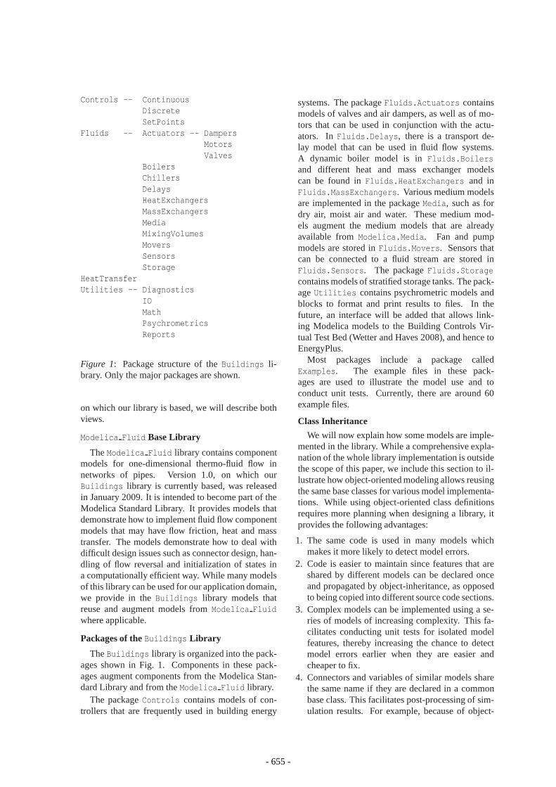
Controls -- ContinuousDiscreteSetPoints
Fluids -- Actuators -- DampersMotorsValves
BoilersChillersDelaysHeatExchangersMassExchangersMediaMixingVolumesMoversSensorsStorage
HeatTransferUtilities -- Diagnostics
IOMathPsychrometricsReports
Figure 1: Package structure of theBuildings li-brary. Only the major packages are shown.
on which our library is based, we will describe bothviews.
Modelica Fluid Base Library
TheModelica Fluid library contains componentmodels for one-dimensional thermo-fluid flow innetworks of pipes. Version 1.0, on which ourBuildings library is currently based, was releasedin January 2009. It is intended to become part of theModelica Standard Library. It provides models thatdemonstrate how to implement fluid flow componentmodels that may have flow friction, heat and masstransfer. The models demonstrate how to deal withdifficult design issues such as connector design, han-dling of flow reversal and initialization of states ina computationally efficient way. While many modelsof this library can be used for our application domain,we provide in theBuildings library models thatreuse and augment models fromModelica Fluidwhere applicable.
Packages of the Buildings Library
TheBuildings library is organized into the pack-ages shown in Fig. 1. Components in these pack-ages augment components from the Modelica Stan-dard Library and from theModelica Fluid library.
The packageControls contains models of con-trollers that are frequently used in building energy
systems. The packageFluids.Actuators containsmodels of valves and air dampers, as well as of mo-tors that can be used in conjunction with the actu-ators. InFluids.Delays, there is a transport de-lay model that can be used in fluid flow systems.A dynamic boiler model is inFluids.Boilersand different heat and mass exchanger modelscan be found inFluids.HeatExchangers and inFluids.MassExchangers. Various medium modelsare implemented in the packageMedia, such as fordry air, moist air and water. These medium mod-els augment the medium models that are alreadyavailable fromModelica.Media. Fan and pumpmodels are stored inFluids.Movers. Sensors thatcan be connected to a fluid stream are stored inFluids.Sensors. The packageFluids.Storagecontains models of stratified storage tanks. The pack-ageUtilities contains psychrometric models andblocks to format and print results to files. In thefuture, an interface will be added that allows link-ing Modelica models to the Building Controls Vir-tual Test Bed (Wetter and Haves 2008), and hence toEnergyPlus.
Most packages include a package calledExamples. The example files in these pack-ages are used to illustrate the model use and toconduct unit tests. Currently, there are around 60example files.
Class Inheritance
We will now explain how some models are imple-mented in the library. While a comprehensive expla-nation of the whole library implementation is outsidethe scope of this paper, we include this section to il-lustrate how object-oriented modeling allows reusingthe same base classes for various model implementa-tions. While using object-oriented class definitionsrequires more planning when designing a library, itprovides the following advantages:
1. The same code is used in many models whichmakes it more likely to detect model errors.
2. Code is easier to maintain since features that areshared by different models can be declared onceand propagated by object-inheritance, as opposedto being copied into different source code sections.
3. Complex models can be implemented using a se-ries of models of increasing complexity. This fa-cilitates conducting unit tests for isolated modelfeatures, thereby increasing the chance to detectmodel errors earlier when they are easier andcheaper to fix.
4. Connectors and variables of similar models sharethe same name if they are declared in a commonbase class. This facilitates post-processing of sim-ulation results. For example, because of object-
- 655 -
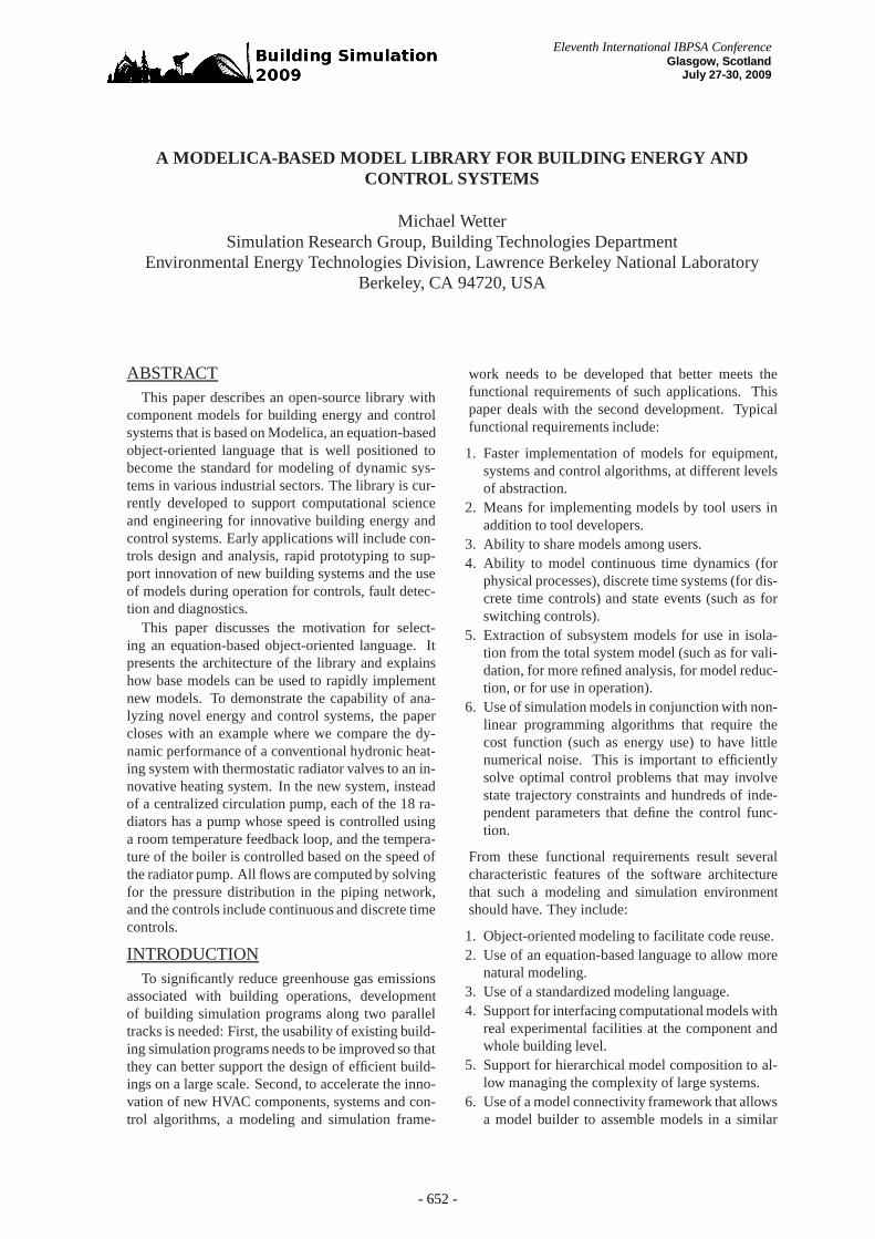
PartialTwoPortTransport
PartialResistance
FixedResistanceDpM PartialActuator
PartialTwoWayValve
TwoWayLinear TwoWayExponential TwoWayQuickOpening
PartialDamperExponential
Exponential VAVBoxExponential
Figure 2: Object-inheritance for pressure drop elements with two fluid ports.
inheritance, a user knows that a flow resistance el-ement always has a public variabledp that reportsthe pressure drop.
5. Inside a system model, component models can beconstrained to belong to a certain base class. Theycan then be redeclared to assign an instance of aparticular model inside a system model. This al-lows treating instances of component models ina similar way to a parameter, thereby allowingchanging the behavior of a model. For example, amodel for heat transfer in a wall can be propagatedinto a building heat transfer model, thereby allow-ing the creation of a building model with differentmodel structure as described in Wetter (2006).
We will now illustrate how object-inheritancewas used to implement two-way valves and airdampers. Figure 2 shows the object-inheritancetree. For the base model, we used the partialmodelPartialTwoPortTransport from the libraryModelica Fluid. This partial model can be used toimplement models that transport a fluid between twoports while conserving enthalpy, mass and speciesconcentration. It defines two instances of a fluidport which are calledport a and port b. It alsodefines a variable that requires a model user to de-clare with what medium this model is used (such asdry air, moist air or water). The model also imple-ments the enthalpy balance as 0= Ha + Hb, the massflow rate balance 0= ma + mb, the species flow ratebalance 0= mX,a + mX,b and the pressure balance∆p = pa − pb. Note that how∆p is computed as afunction of the flow rate is not yet specified, sincethe equation will be different for different models.
Next, there is a model calledPartialResistance. This model implements afunction that computes the mass flow rate as a func-tion of pressure drop, ˙m = f (k,∆p). The functionf (·, ·) is an approximation to ˙m= sign(∆p)k
√
|∆p|with regularization near zero for numerical reasonsand to capture the laminar flow region. Howkis computed is not specified at this level of the
object-inheritance tree.4
There are two different models for specifyingk.The modelFixedResistanceDpM is a model for afixed flow resistance in which the user can specifythe point on the curve that relates mass flow rate withpressure drop. Given a nominal mass flow rate ˙m0
and a correspondingpressure drop∆p0, the model as-signsk = m0/
√∆p0. There are also parameters that
allow a model user to specify where the transition be-tween turbulent and laminar flow occurs. In contrastto this model, the modelPartialActuator does notdefine howk is computed, because different actuatorsrequire different equations. Instead, it simply instan-tiates a connector for an input signal whose value isequal to the actuator opening, withy = 0 defined asclosed andy = 1 defined as open.
Next, the modelPartialActuator implementsa partial model for a damper, i.e., the modelPartialDamperExponential, and a partial modelfor a two-way valve, i.e.,PartialTwoWayValve.The model PartialTwoWayValve defines that avalve implementation needs to specify a flow func-tion φ(y) = k(y)/k(y= 1) that relates the valve open-ing y with the actual flow coefficientk(y) and theflow coefficient for a fully open valve,k(y = 1). Italso specifies a parameter for the valve leakagel , i.e,l = k(0) so thatφ(0) = l/k(y = 1).
All these partial models are stored in packagescalledBaseClasses that a typical model user doesnot need to browse when assembling a system model.
Next, there is a package calledValves withthe model TwoWayLinear which implementsthe linear characteristicsφ(y) = l + y(1 − l),and the modelsTwoWayEqualPercentage andTwoWayQuickOpening that implement valve open-ing characteristics for equal percentage and forquick opening valves. There is also a package calledDampers that implements models for an air damperand a variable air volume flow box with exponential
4We used mass flow rate instead of volume flow rate as thisleads to simpler equations. However, it would be easy to imple-ment a model in which a user can specify the volume flow rateinstead of the mass flow rate.
- 656 -
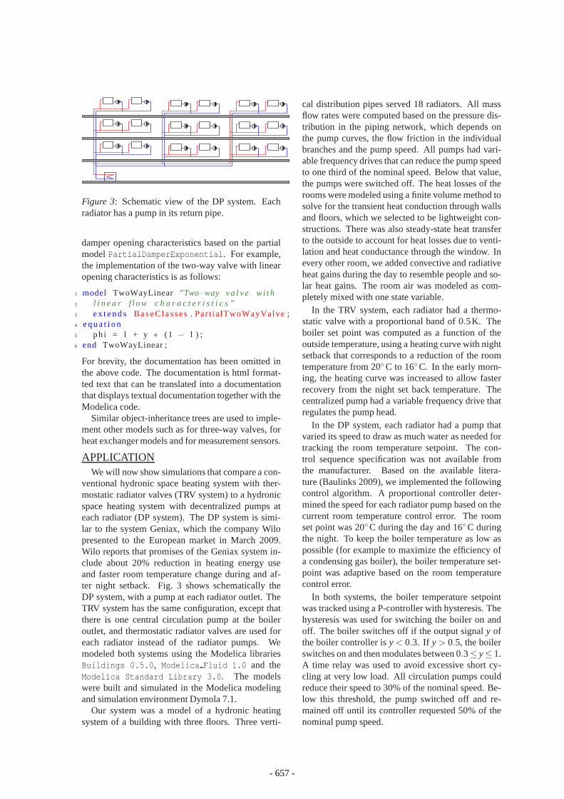
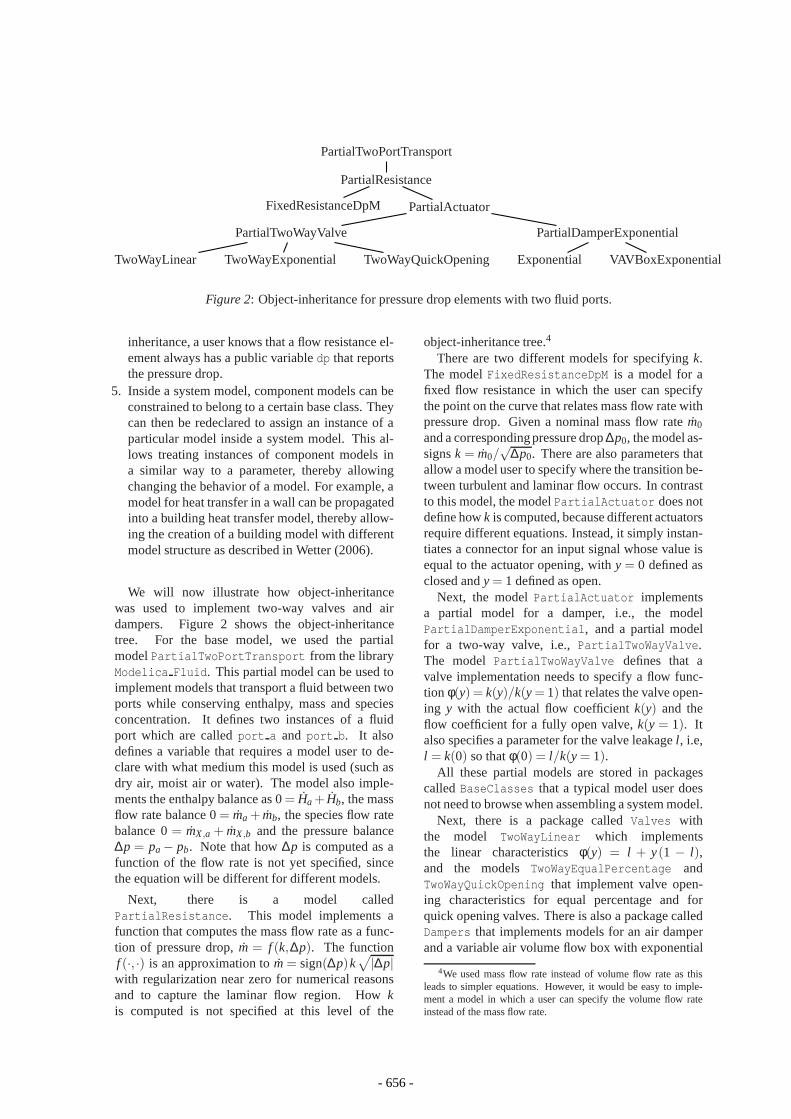
Figure 3: Schematic view of the DP system. Eachradiator has a pump in its return pipe.
damper opening characteristics based on the partialmodelPartialDamperExponential. For example,the implementation of the two-way valve with linearopening characteristics is as follows:
1 model TwoWayLinear ”Two−way v a l v e w i t h2 l i n e a r f l ow c h a r a c t e r i s t i c s ”3 e x t e n d s BaseC lasses. Par t ia lTwoWayValve;4 e q u a t i o n5 ph i = l + y ∗ (1 − l ) ;6 end TwoWayLinear ;
For brevity, the documentation has been omitted inthe above code. The documentation is html format-ted text that can be translated into a documentationthat displays textual documentation together with theModelica code.
Similar object-inheritance trees are used to imple-ment other models such as for three-way valves, forheat exchanger models and for measurement sensors.
APPLICATIONWe will now show simulations that compare a con-
ventional hydronic space heating system with ther-mostatic radiator valves (TRV system) to a hydronicspace heating system with decentralized pumps ateach radiator (DP system). The DP system is simi-lar to the system Geniax, which the company Wilopresented to the European market in March 2009.Wilo reports that promises of the Geniax system in-clude about 20% reduction in heating energy useand faster room temperature change during and af-ter night setback. Fig. 3 shows schematically theDP system, with a pump at each radiator outlet. TheTRV system has the same configuration, except thatthere is one central circulation pump at the boileroutlet, and thermostatic radiator valves are used foreach radiator instead of the radiator pumps. Wemodeled both systems using the Modelica librariesBuildings 0.5.0, Modelica Fluid 1.0 and theModelica Standard Library 3.0. The modelswere built and simulated in the Modelica modelingand simulation environment Dymola 7.1.
Our system was a model of a hydronic heatingsystem of a building with three floors. Three verti-
cal distribution pipes served 18 radiators. All massflow rates were computed based on the pressure dis-tribution in the piping network, which depends onthe pump curves, the flow friction in the individualbranches and the pump speed. All pumps had vari-able frequency drives that can reduce the pump speedto one third of the nominal speed. Below that value,the pumps were switched off. The heat losses of therooms were modeled using a finite volume method tosolve for the transient heat conduction through wallsand floors, which we selected to be lightweight con-structions. There was also steady-state heat transferto the outside to account for heat losses due to venti-lation and heat conductance through the window. Inevery other room, we added convective and radiativeheat gains during the day to resemble people and so-lar heat gains. The room air was modeled as com-pletely mixed with one state variable.
In the TRV system, each radiator had a thermo-static valve with a proportional band of 0.5K. Theboiler set point was computed as a function of theoutside temperature, using a heating curve with nightsetback that corresponds to a reduction of the roomtemperature from 20◦C to 16◦C. In the early morn-ing, the heating curve was increased to allow fasterrecovery from the night set back temperature. Thecentralized pump had a variable frequency drive thatregulates the pump head.
In the DP system, each radiator had a pump thatvaried its speed to draw as much water as needed fortracking the room temperature setpoint. The con-trol sequence specification was not available fromthe manufacturer. Based on the available litera-ture (Baulinks 2009), we implemented the followingcontrol algorithm. A proportional controller deter-mined the speed for each radiator pump based on thecurrent room temperature control error. The roomset point was 20◦C during the day and 16◦C duringthe night. To keep the boiler temperature as low aspossible (for example to maximize the efficiency ofa condensing gas boiler), the boiler temperature set-point was adaptive based on the room temperaturecontrol error.
In both systems, the boiler temperature setpointwas tracked using a P-controller with hysteresis. Thehysteresis was used for switching the boiler on andoff. The boiler switches off if the output signaly ofthe boiler controller isy < 0.3. If y > 0.5, the boilerswitches on and then modulates between 0.3≤ y≤ 1.A time relay was used to avoid excessive short cy-cling at very low load. All circulation pumps couldreduce their speed to 30% of the nominal speed. Be-low this threshold, the pump switched off and re-mained off until its controller requested 50% of thenominal pump speed.
- 657 -
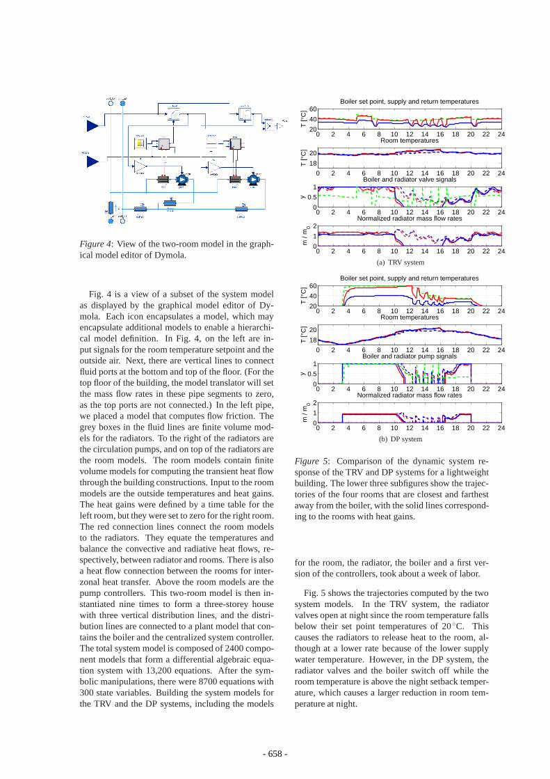
Figure 4: View of the two-room model in the graph-ical model editor of Dymola.
Fig. 4 is a view of a subset of the system modelas displayed by the graphical model editor of Dy-mola. Each icon encapsulates a model, which mayencapsulate additional models to enable a hierarchi-cal model definition. In Fig. 4, on the left are in-put signals for the room temperature setpoint and theoutside air. Next, there are vertical lines to connectfluid ports at the bottom and top of the floor. (For thetop floor of the building, the model translator will setthe mass flow rates in these pipe segments to zero,as the top ports are not connected.) In the left pipe,we placed a model that computes flow friction. Thegrey boxes in the fluid lines are finite volume mod-els for the radiators. To the right of the radiators arethe circulation pumps, and on top of the radiators arethe room models. The room models contain finitevolume models for computing the transient heat flowthrough the building constructions. Input to the roommodels are the outside temperatures and heat gains.The heat gains were defined by a time table for theleft room, but they were set to zero for the right room.The red connection lines connect the room modelsto the radiators. They equate the temperatures andbalance the convective and radiative heat flows, re-spectively, between radiator and rooms. There is alsoa heat flow connection between the rooms for inter-zonal heat transfer. Above the room models are thepump controllers. This two-room model is then in-stantiated nine times to form a three-storey housewith three vertical distribution lines, and the distri-bution lines are connected to a plant model that con-tains the boiler and the centralized system controller.The total system model is composed of 2400 compo-nent models that form a differential algebraic equa-tion system with 13,200 equations. After the sym-bolic manipulations, there were 8700 equations with300 state variables. Building the system models forthe TRV and the DP systems, including the models
0 2 4 6 8 10 12 14 16 18 20 22 2420
40
60
T [°
C]
Boiler set point, supply and return temperatures
0 2 4 6 8 10 12 14 16 18 20 22 24
18
20
T [°
C]
Room temperatures
0 2 4 6 8 10 12 14 16 18 20 22 240
0.5
1Boiler and radiator valve signals
y
0 2 4 6 8 10 12 14 16 18 20 22 240
1
2Normalized radiator mass flow rates
m /
m0
(a) TRV system
0 2 4 6 8 10 12 14 16 18 20 22 2420
40
60
T [°
C]
Boiler set point, supply and return temperatures
0 2 4 6 8 10 12 14 16 18 20 22 24
18
20
T [°
C]
Room temperatures
0 2 4 6 8 10 12 14 16 18 20 22 240
0.5
1Boiler and radiator pump signals
y
0 2 4 6 8 10 12 14 16 18 20 22 240
1
2Normalized radiator mass flow rates
m /
m0
(b) DP system
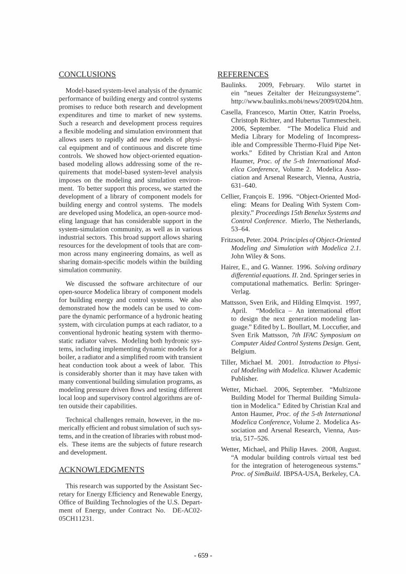
Figure 5: Comparison of the dynamic system re-sponse of the TRV and DP systems for a lightweightbuilding. The lower three subfigures show the trajec-tories of the four rooms that are closest and farthestaway from the boiler, with the solid lines correspond-ing to the rooms with heat gains.
for the room, the radiator, the boiler and a first ver-sion of the controllers, took about a week of labor.
Fig. 5 shows the trajectories computed by the twosystem models. In the TRV system, the radiatorvalves open at night since the room temperature fallsbelow their set point temperatures of 20◦C. Thiscauses the radiators to release heat to the room, al-though at a lower rate because of the lower supplywater temperature. However, in the DP system, theradiator valves and the boiler switch off while theroom temperature is above the night setback temper-ature, which causes a larger reduction in room tem-perature at night.
- 658 -
CONCLUSIONS
Model-based system-level analysis of the dynamicperformance of building energy and control systemspromises to reduce both research and developmentexpenditures and time to market of new systems.Such a research and development process requiresa flexible modeling and simulation environment thatallows users to rapidly add new models of physi-cal equipment and of continuous and discrete timecontrols. We showed how object-oriented equation-based modeling allows addressing some of the re-quirements that model-based system-level analysisimposes on the modeling and simulation environ-ment. To better support this process, we started thedevelopment of a library of component models forbuilding energy and control systems. The modelsare developed using Modelica, an open-source mod-eling language that has considerable support in thesystem-simulation community, as well as in variousindustrial sectors. This broad support allows sharingresources for the development of tools that are com-mon across many engineering domains, as well assharing domain-specific models within the buildingsimulation community.
We discussed the software architecture of ouropen-source Modelica library of component modelsfor building energy and control systems. We alsodemonstrated how the models can be used to com-pare the dynamic performance of a hydronic heatingsystem, with circulation pumps at each radiator, to aconventional hydronic heating system with thermo-static radiator valves. Modeling both hydronic sys-tems, including implementing dynamic models for aboiler, a radiator and a simplified room with transientheat conduction took about a week of labor. Thisis considerably shorter than it may have taken withmany conventional building simulation programs, asmodeling pressure driven flows and testing differentlocal loop and supervisory control algorithms are of-ten outside their capabilities.
Technical challenges remain, however, in the nu-merically efficient and robust simulation of such sys-tems, and in the creation of libraries with robust mod-els. These items are the subjects of future researchand development.
ACKNOWLEDGMENTS
This research was supported by the Assistant Sec-retary for Energy Efficiency and Renewable Energy,Office of Building Technologies of the U.S. Depart-ment of Energy, under Contract No. DE-AC02-05CH11231.
REFERENCESBaulinks. 2009, February. Wilo startet in
ein ”neues Zeitalter der Heizungssysteme”.http://www.baulinks.mobi/news/2009/0204.htm.
Casella, Francesco, Martin Otter, Katrin Proelss,Christoph Richter, and Hubertus Tummescheit.2006, September. “The Modelica Fluid andMedia Library for Modeling of Incompress-ible and Compressible Thermo-Fluid Pipe Net-works.” Edited by Christian Kral and AntonHaumer,Proc. of the 5-th International Mod-elica Conference, Volume 2. Modelica Asso-ciation and Arsenal Research, Vienna, Austria,631–640.
Cellier, Francois E. 1996. “Object-Oriented Mod-eling: Means for Dealing With System Com-plexity.” Proceedings 15th Benelux Systems andControl Conference. Mierlo, The Netherlands,53–64.
Fritzson, Peter. 2004.Principles of Object-OrientedModeling and Simulation with Modelica 2.1.John Wiley & Sons.
Hairer, E., and G. Wanner. 1996.Solving ordinarydifferential equations. II. 2nd. Springer series incomputational mathematics. Berlin: Springer-Verlag.
Mattsson, Sven Erik, and Hilding Elmqvist. 1997,April. “Modelica – An international effortto design the next generation modeling lan-guage.” Edited by L. Boullart, M. Loccufier, andSven Erik Mattsson,7th IFAC Symposium onComputer Aided Control Systems Design. Gent,Belgium.
Tiller, Michael M. 2001. Introduction to Physi-cal Modeling with Modelica. Kluwer AcademicPublisher.
Wetter, Michael. 2006, September. “MultizoneBuilding Model for Thermal Building Simula-tion in Modelica.” Edited by Christian Kral andAnton Haumer,Proc. of the 5-th InternationalModelica Conference, Volume 2. Modelica As-sociation and Arsenal Research, Vienna, Aus-tria, 517–526.
Wetter, Michael, and Philip Haves. 2008, August.“A modular building controls virtual test bedfor the integration of heterogeneous systems.”Proc. of SimBuild. IBPSA-USA, Berkeley, CA.
- 659 -


