Embed Size (px)
Citation preview
Maintenance
Base Station Controller
MMN:BSC
A30808-X3247-K220-4-7620

2 A30808-X3247-K220-4-7620
MMN:BSC MaintenanceBase Station Controller
! Important Notice on Product Safety
DANGER - RISK OF ELECTRICAL SHOCK OR DEATH - FOLLOW ALL INSTALLATIONINSTRUCTIONS.
The system complies with the standard EN 60950 / IEC 60950. All equipment connected to thesystem must comply with the applicable safety standards.Hazardous voltages are present at the AC power supply lines in this electrical equipment. Somecomponents may also have high operating temperatures.Failure to observe and follow all installation and safety instructions can result in seriouspersonal injury or property damage.Therefore, only trained and qualified personnel may install and maintain the system.
The same text in German:
Wichtiger Hinweis zur Produktsicherheit
LEBENSGEFAHR - BEACHTEN SIE ALLE INSTALLATIONSHINWEISE.
Das System entspricht den Anforderungen der EN 60950 / IEC 60950. Alle an das System angeschlo-ssenen Geräte müssen die zutreffenden Sicherheitsbestimmungen erfüllen.In diesen Anlagen stehen die Netzversorgungsleitungen unter gefährlicher Spannung. EinigeKomponenten können auch eine hohe Betriebstemperatur aufweisen.Nichtbeachtung der Installations- und Sicherheitshinweise kann zu schweren Körperverlet-zungen oder Sachschäden führen.Deshalb darf nur geschultes und qualifiziertes Personal das System installieren und warten.
Caution:This equipment has been tested and found to comply with EN 301489. Its class of conformity isdefined in table A30808-X3247-X910-*-7618, which is shipped with each product. This class alsocorresponds to the limits for a Class A digital device, pursuant to part 15 of the FCC Rules.These limits are designed to provide reasonable protection against harmful interference when theequipment is operated in a commercial environment.This equipment generates, uses and can radiate radio frequency energy and, if not installed and usedin accordance with the relevant standards referenced in the manual “Guide to Documentation”, maycause harmful interference to radio communications.For system installations it is strictly required to choose all installation sites according to national andlocal requirements concerning construction rules and static load capacities of buildings and roofs.For all sites, in particular in residential areas it is mandatory to observe all respectively applicableelectromagnetic field / force (EMF) limits. Otherwise harmful personal interference is possible.
Trademarks:
All designations used in this document can be trademarks, the use of which by third parties for their own purposescould violate the rights of their owners.
Copyright (C) Siemens AG 2002.
Issued by the Information and Communication Mobile GroupHofmannstraße 51D-81359 München
Technical modifications possible.Technical specifications and features are binding only insofar asthey are specifically and expressly agreed upon in a written contract.

A30808-X3247-K220-4-7620 3
MaintenanceBase Station Controller
MMN:BSC
IssuesChange indications (Ind.):
N = new; G = modified; 0 = deleted;
Document Title Page(s) Issue/Ind.
MMN:BSC . . . . . . . . . . . 1...250 4

4 A30808-X3247-K220-4-7620
MMN:BSC MaintenanceBase Station Controller
A30808-X3247-K220-4-7620 5
MaintenanceBase Station Controller
MMN:BSC
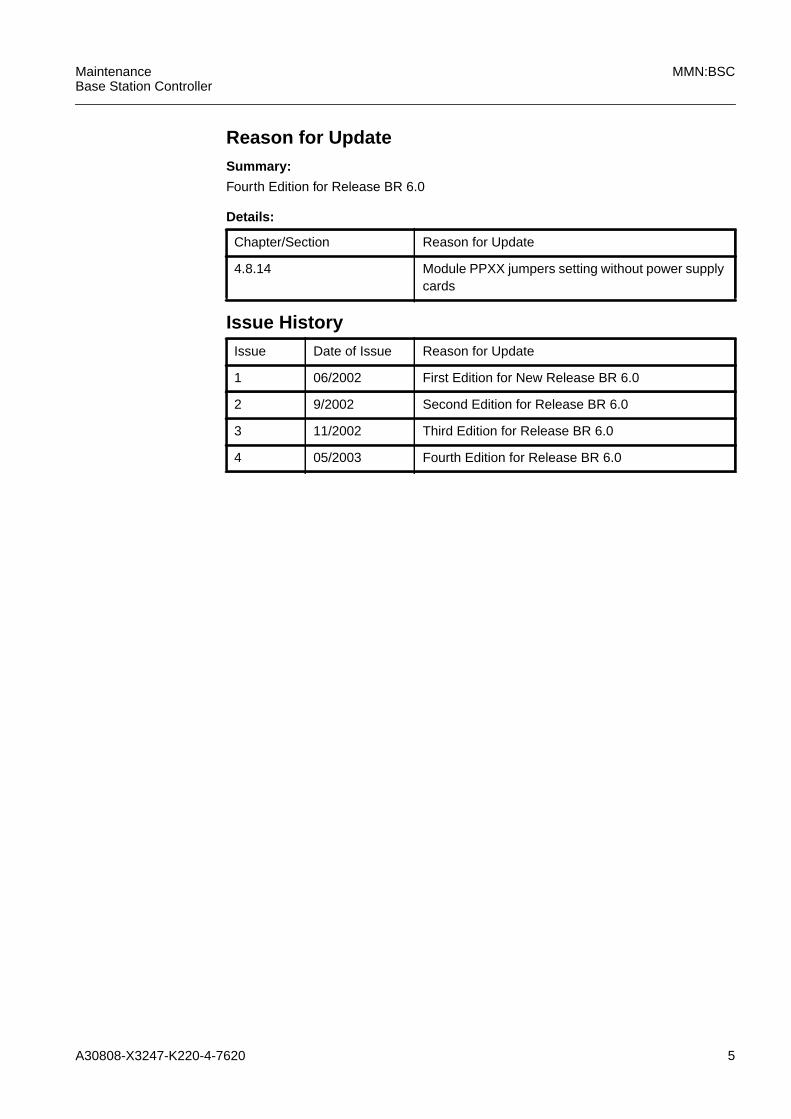
Reason for UpdateSummary:
Fourth Edition for Release BR 6.0
Details:
Chapter/Section Reason for Update
4.8.14 Module PPXX jumpers setting without power supplycards
Issue HistoryIssue Date of Issue Reason for Update
1 06/2002 First Edition for New Release BR 6.0
2 9/2002 Second Edition for Release BR 6.0
3 11/2002 Third Edition for Release BR 6.0
4 05/2003 Fourth Edition for Release BR 6.0

6 A30808-X3247-K220-4-7620
MMN:BSC MaintenanceBase Station Controller

A30808-X3247-K220-4-7620 7
MaintenanceBase Station Controller
MMN:BSC
Contents
1 Introduction . . . . . . . . . . . . . . . . . . . . . . . . . . . . . . . . . . . . . . . . . . . . . . . . . 131.1 Structure of the Maintenance Manual . . . . . . . . . . . . . . . . . . . . . . . . . . . . . 131.2 Symbols used . . . . . . . . . . . . . . . . . . . . . . . . . . . . . . . . . . . . . . . . . . . . . . . 141.3 Fault Clearance Principle . . . . . . . . . . . . . . . . . . . . . . . . . . . . . . . . . . . . . . 151.4 Fault Clearance Guidelines. . . . . . . . . . . . . . . . . . . . . . . . . . . . . . . . . . . . . 161.5 Module Replacement Instructions. . . . . . . . . . . . . . . . . . . . . . . . . . . . . . . . 181.6 Fault Management Procedure . . . . . . . . . . . . . . . . . . . . . . . . . . . . . . . . . . 201.7 Procedures references . . . . . . . . . . . . . . . . . . . . . . . . . . . . . . . . . . . . . . . . 24
2 Tasklist . . . . . . . . . . . . . . . . . . . . . . . . . . . . . . . . . . . . . . . . . . . . . . . . . . . . 41
3 Fault Clearance Procedures for Modules and Interfaces . . . . . . . . . . . . . . 433.1 Diagnostic Procedure . . . . . . . . . . . . . . . . . . . . . . . . . . . . . . . . . . . . . . . . . 453.2 DISK . . . . . . . . . . . . . . . . . . . . . . . . . . . . . . . . . . . . . . . . . . . . . . . . . . . . . . 473.3 DK40 . . . . . . . . . . . . . . . . . . . . . . . . . . . . . . . . . . . . . . . . . . . . . . . . . . . . . . 533.4 IXLT . . . . . . . . . . . . . . . . . . . . . . . . . . . . . . . . . . . . . . . . . . . . . . . . . . . . . . 573.5 MEMT . . . . . . . . . . . . . . . . . . . . . . . . . . . . . . . . . . . . . . . . . . . . . . . . . . . . . 613.6 MPCC . . . . . . . . . . . . . . . . . . . . . . . . . . . . . . . . . . . . . . . . . . . . . . . . . . . . . 653.7 NTW Procedure . . . . . . . . . . . . . . . . . . . . . . . . . . . . . . . . . . . . . . . . . . . . . 693.8 PLLH . . . . . . . . . . . . . . . . . . . . . . . . . . . . . . . . . . . . . . . . . . . . . . . . . . . . . . 713.9 PPCC . . . . . . . . . . . . . . . . . . . . . . . . . . . . . . . . . . . . . . . . . . . . . . . . . . . . . 753.10 PPCU . . . . . . . . . . . . . . . . . . . . . . . . . . . . . . . . . . . . . . . . . . . . . . . . . . . . . 793.11 PPLD. . . . . . . . . . . . . . . . . . . . . . . . . . . . . . . . . . . . . . . . . . . . . . . . . . . . . . 813.12 PPXL. . . . . . . . . . . . . . . . . . . . . . . . . . . . . . . . . . . . . . . . . . . . . . . . . . . . . . 853.13 PPXU . . . . . . . . . . . . . . . . . . . . . . . . . . . . . . . . . . . . . . . . . . . . . . . . . . . . . 873.14 PWRS (PWRD or EPWR). . . . . . . . . . . . . . . . . . . . . . . . . . . . . . . . . . . . . . 893.15 QTLP. . . . . . . . . . . . . . . . . . . . . . . . . . . . . . . . . . . . . . . . . . . . . . . . . . . . . . 933.16 Remote Inventory Data . . . . . . . . . . . . . . . . . . . . . . . . . . . . . . . . . . . . . . . . 973.17 SN16 . . . . . . . . . . . . . . . . . . . . . . . . . . . . . . . . . . . . . . . . . . . . . . . . . . . . . 1053.18 SNAP . . . . . . . . . . . . . . . . . . . . . . . . . . . . . . . . . . . . . . . . . . . . . . . . . . . . 1093.19 TDPC . . . . . . . . . . . . . . . . . . . . . . . . . . . . . . . . . . . . . . . . . . . . . . . . . . . . 1133.20 UBEX . . . . . . . . . . . . . . . . . . . . . . . . . . . . . . . . . . . . . . . . . . . . . . . . . . . . 117
4 Hardware Equipment . . . . . . . . . . . . . . . . . . . . . . . . . . . . . . . . . . . . . . . . 1214.1 Rack Connections. . . . . . . . . . . . . . . . . . . . . . . . . . . . . . . . . . . . . . . . . . . 1294.2 Rack Connection for BC120-HC . . . . . . . . . . . . . . . . . . . . . . . . . . . . . . . . 1314.3 Fuse and Alarm Panel of the C20-X rack . . . . . . . . . . . . . . . . . . . . . . . . . 1344.4 Lamp Panel. . . . . . . . . . . . . . . . . . . . . . . . . . . . . . . . . . . . . . . . . . . . . . . . 1364.5 DC-Panel of the BC120-HC (C38-X rack). . . . . . . . . . . . . . . . . . . . . . . . . 1374.6 Temperature Sensors . . . . . . . . . . . . . . . . . . . . . . . . . . . . . . . . . . . . . . . . 1384.7 Power Supply . . . . . . . . . . . . . . . . . . . . . . . . . . . . . . . . . . . . . . . . . . . . . . 1394.8 Jumpers setting. . . . . . . . . . . . . . . . . . . . . . . . . . . . . . . . . . . . . . . . . . . . . 141
5 Appendix . . . . . . . . . . . . . . . . . . . . . . . . . . . . . . . . . . . . . . . . . . . . . . . . . . 1775.1 Alarm Handling . . . . . . . . . . . . . . . . . . . . . . . . . . . . . . . . . . . . . . . . . . . . . 1775.2 Alarm Reporting . . . . . . . . . . . . . . . . . . . . . . . . . . . . . . . . . . . . . . . . . . . . 1795.3 Failure Event Message . . . . . . . . . . . . . . . . . . . . . . . . . . . . . . . . . . . . . . . 1835.4 General diagnostic structure . . . . . . . . . . . . . . . . . . . . . . . . . . . . . . . . . . . 187
8 A30808-X3247-K220-4-7620
MMN:BSC MaintenanceBase Station Controller
5.5 NACK CAUSES . . . . . . . . . . . . . . . . . . . . . . . . . . . . . . . . . . . . . . . . . . . . . 248
6 Abbreviations . . . . . . . . . . . . . . . . . . . . . . . . . . . . . . . . . . . . . . . . . . . . . . . 249

A30808-X3247-K220-4-7620 9
MaintenanceBase Station Controller
MMN:BSC
IllustrationsFig. 1.1 Structure of the MMN:BSC . . . . . . . . . . . . . . . . . . . . . . . . . . . . . . . . . . 13
Fig. 1.2 Used Symbols . . . . . . . . . . . . . . . . . . . . . . . . . . . . . . . . . . . . . . . . . . . . 14
Fig. 1.3 Fault Clearance Overview . . . . . . . . . . . . . . . . . . . . . . . . . . . . . . . . . . . 16
Fig. 1.4 ESD Symbol. . . . . . . . . . . . . . . . . . . . . . . . . . . . . . . . . . . . . . . . . . . . . . 18
Fig. 1.5 General Maintenance flow chart . . . . . . . . . . . . . . . . . . . . . . . . . . . . . . 21
Fig. 3.1 Delete nob_Record . . . . . . . . . . . . . . . . . . . . . . . . . . . . . . . . . . . . . . . . 97
Fig. 3.2 Create nob_Record . . . . . . . . . . . . . . . . . . . . . . . . . . . . . . . . . . . . . . . . 98
Fig. 3.3 Edit nob_Record . . . . . . . . . . . . . . . . . . . . . . . . . . . . . . . . . . . . . . . . . . 98
Fig. 3.4 Attach nob_RIU file . . . . . . . . . . . . . . . . . . . . . . . . . . . . . . . . . . . . . . . . 99
Fig. 4.1 Regular capacity BSC - Rack Layout and Size . . . . . . . . . . . . . . . . . . 122
Fig. 4.2 Regular capacity BSC frame for the GPRS feature . . . . . . . . . . . . . . . 123
Fig. 4.3 High Capacity BSC frame . . . . . . . . . . . . . . . . . . . . . . . . . . . . . . . . . . 124
Fig. 4.4 High Capacity BSC in fire resistence cabinet version . . . . . . . . . . . . . 125
Fig. 4.5 High Capacity BC120HC (S30861-C36-X) . . . . . . . . . . . . . . . . . . . . . 126
Fig. 4.6 BSC Rack Connection Blocks . . . . . . . . . . . . . . . . . . . . . . . . . . . . . . . 129
Fig. 4.7 RCAP in the BC120 - HC. . . . . . . . . . . . . . . . . . . . . . . . . . . . . . . . . . . 131
Fig. 4.8 Alarm LEDs on the BSC Fuse and Alarm Panel . . . . . . . . . . . . . . . . . 134
Fig. 4.9 BSC Fuse and Alarm Panel, Part with Fuses . . . . . . . . . . . . . . . . . . . 136
Fig. 4.10 Lamp Panel . . . . . . . . . . . . . . . . . . . . . . . . . . . . . . . . . . . . . . . . . . . . . 136
Fig. 4.11 Alarm LEDs for BC120 HC . . . . . . . . . . . . . . . . . . . . . . . . . . . . . . . . . 137
Fig. 4.12 DC-Panel for BC120 HC . . . . . . . . . . . . . . . . . . . . . . . . . . . . . . . . . . . 137
Fig. 4.13 BSC Power Supply Module Panel . . . . . . . . . . . . . . . . . . . . . . . . . . . . 139
Fig. 4.14 Jumpers Setting for Module DK40. . . . . . . . . . . . . . . . . . . . . . . . . . . . 141
Fig. 4.15 Jumpers Setting for Module DK40 V2 and V3 . . . . . . . . . . . . . . . . . . . 142
Fig. 4.16 Jumpers Setting for Module IXLT V3 and V4. . . . . . . . . . . . . . . . . . . . 143
Fig. 4.17 Jumpers Setting for Module IXLT V6 and V7. . . . . . . . . . . . . . . . . . . . 144
Fig. 4.18 Jumpers Setting for Module MEMT . . . . . . . . . . . . . . . . . . . . . . . . . . . 145
Fig. 4.19 Jumpers Setting for Module MPCC V7 . . . . . . . . . . . . . . . . . . . . . . . . 146
Fig. 4.20 Front View of MPCC V7. . . . . . . . . . . . . . . . . . . . . . . . . . . . . . . . . . . . 147
Fig. 4.21 Jumpers Setting for Module PLLH (75 Ohm). . . . . . . . . . . . . . . . . . . . 149
Fig. 4.22 Jumpers Setting for Module PLLH (120 Ohm). . . . . . . . . . . . . . . . . . . 150
Fig. 4.23 Jumpers Setting for Module PLLH V2 (75 Ohm) . . . . . . . . . . . . . . . . . 151
Fig. 4.24 Jumpers Setting for Module PLLH V2 (120 Ohm) . . . . . . . . . . . . . . . . 152
Fig. 4.25 Jumpers Setting for Module PPCC V2. . . . . . . . . . . . . . . . . . . . . . . . . 153
Fig. 4.26 Jumpers Setting for Module PPCC V3. . . . . . . . . . . . . . . . . . . . . . . . . 154
Fig. 4.27 Jumpers Setting for Module PPCU . . . . . . . . . . . . . . . . . . . . . . . . . . . 155
Fig. 4.28 Jumpers Setting for Module PPLD V2 . . . . . . . . . . . . . . . . . . . . . . . . . 156
Fig. 4.29 Jumper setting for module PPLD V3 . . . . . . . . . . . . . . . . . . . . . . . . . . 157
Fig. 4.30 Jumpers Setting for Module QTLP (120 Ohm) . . . . . . . . . . . . . . . . . . 158
Fig. 4.31 Jumpers Setting for Module QTLP (75 Ohm) . . . . . . . . . . . . . . . . . . . 159
Fig. 4.32 Jumpers Setting for Module QTLP V2 (75 Ohm) . . . . . . . . . . . . . . . . . 160
Fig. 4.33 Jumpers Setting for Module QTLP V2 (100 Ohm) . . . . . . . . . . . . . . . . 161
Fig. 4.34 Jumpers Setting for Module QTLP V2 (120 Ohm) . . . . . . . . . . . . . . . . 162
10 A30808-X3247-K220-4-7620
MMN:BSC MaintenanceBase Station Controller
Fig. 4.35 PCM Monitoring Points for QTLP and QTLP V2. . . . . . . . . . . . . . . . . . 163
Fig. 4.36 Jumpers Setting for Module SN16 . . . . . . . . . . . . . . . . . . . . . . . . . . . . 165
Fig. 4.37 Jumpers Setting for Module TDPC V6 . . . . . . . . . . . . . . . . . . . . . . . . . 166
Fig. 4.38 Front View of TDPC V6. . . . . . . . . . . . . . . . . . . . . . . . . . . . . . . . . . . . . 167
Fig. 4.39 Jumpers Setting for Module UBEX . . . . . . . . . . . . . . . . . . . . . . . . . . . . 169
Fig. 4.40 Jumpers Setting for Module SNAP V1 . . . . . . . . . . . . . . . . . . . . . . . . . 170
Fig. 4.41 Jumpers Setting for Module PPXX (fed by EPWR power supply card) 171
Fig. 4.42 Jumpers Setting for Module PPXX (fed by internal power supply module)172
Fig. 4.43 Jumpers Setting for Module STLP . . . . . . . . . . . . . . . . . . . . . . . . . . . . 173
Fig. 5.1 The BSC Maintenance Entity Graph (MEG tree) for BSC Regular Capacity181
Fig. 5.2 The BSC Maintenance Entity Graph (MEG tree) for BSC High Capacity . .182
A30808-X3247-K220-4-7620 11
MaintenanceBase Station Controller
MMN:BSC
TablesTab. 1.1 Alarms list . . . . . . . . . . . . . . . . . . . . . . . . . . . . . . . . . . . . . . . . . . . . . . . 24
Tab. 2.1 Fuse Electrical Data. . . . . . . . . . . . . . . . . . . . . . . . . . . . . . . . . . . . . . . . 41
Tab. 3.1 List of nob_RIUs for BSC Standard . . . . . . . . . . . . . . . . . . . . . . . . . . . . 99
Tab. 3.2 List of nob_RIUs for BSC High Capacity . . . . . . . . . . . . . . . . . . . . . . . 100
Tab. 4.1 Assignment of even and odd PCM Links to SUB-D 37 Connectors . . 130
Tab. 4.2 Cross references for PCM lines . . . . . . . . . . . . . . . . . . . . . . . . . . . . . . 132
Tab. 4.3 Signal pin connector on SUB D37 . . . . . . . . . . . . . . . . . . . . . . . . . . . . 132
Tab. 4.4 LED-Hardware Correspondence . . . . . . . . . . . . . . . . . . . . . . . . . . . . . 135
Tab. 4.5 Anomaly Conditions identified by LEDs. . . . . . . . . . . . . . . . . . . . . . . . 140
Tab. 4.6 Description of QTLP and QTLP V2 Monitoring Points . . . . . . . . . . . . . 163
Tab. 4.7 Jumpers STLP . . . . . . . . . . . . . . . . . . . . . . . . . . . . . . . . . . . . . . . . . . . 174
Tab. 5.1 New Phase Identifiers . . . . . . . . . . . . . . . . . . . . . . . . . . . . . . . . . . . . . 190
Tab. 5.2 Error Codes used by PWRS, MPCC, TDPC, MEMT Diagnosis . . . . . 197
Tab. 5.3 Error Codes used by NTW Diagnostics . . . . . . . . . . . . . . . . . . . . . . . . 202
Tab. 5.4 Error Codes used by PPxx Diagnostics . . . . . . . . . . . . . . . . . . . . . . . . 209
Tab. 5.5 Error Codes used by LICD Diagnostics . . . . . . . . . . . . . . . . . . . . . . . . 214
Tab. 5.6 DK40: Test-id Values . . . . . . . . . . . . . . . . . . . . . . . . . . . . . . . . . . . . . . 221
Tab. 5.7 List of phases that are executed in the several conditions . . . . . . . . . 223
Tab. 5.8 IXLT: Test-id Values . . . . . . . . . . . . . . . . . . . . . . . . . . . . . . . . . . . . . . 227
Tab. 5.9 PPCU: Test-id Values . . . . . . . . . . . . . . . . . . . . . . . . . . . . . . . . . . . . . 237
Tab. 5.10 PPXU: Test-id Values . . . . . . . . . . . . . . . . . . . . . . . . . . . . . . . . . . . . . 247

12 A30808-X3247-K220-4-7620
MMN:BSC MaintenanceBase Station Controller

A30808-X3247-K220-4-7620 13
MaintenanceBase Station Controller
MMN:BSC
1 Introduction
1.1 Structure of the Maintenance Manual
The following diagram gives an overview of the structure of this manual and the purposeof its chapters.
Fig. 1.1 Structure of the MMN:BSC
Chapter 1
Chapter 2
Chapter 3
Chapter 5
Introduction– Basic information on this manual– Basic information on fault clearance– Guidelines– General replacement Instructions– Preparatory work if relevant
Chapter 6 Abbreviations
AppendixBasic required knowledge in more detail,e.g. fault messages
Chapter 4
Fault Clearance Procedures for Modulesand Interfaces– Fault clearance procedures for modules
and interfaces in alphabetical order– Concluding procedure “Remote Inventory
Data” that some fault clearanceprocedures require (if necessary, links areprovided to this concluding procedure)
Tables, Lists and Figures– Information on replaceable modules,
e.g. LEDs, connectors etc.– Overview of the HW architecture as
additional information
(Important information to make your workefficient and safe)
(Main Part for Fault Clearance Tasks)
(Reference Chapter)
(Reference Chapter)
(General Maintenance)
(Reference Chapter)
Chapter 4
Task ListInformation on routine tasks that need to becarried out

14 A30808-X3247-K220-4-7620
MMN:BSC MaintenanceBase Station Controller
1.2 Symbols used
The following symbols are used throughout this manual:
Fig. 1.2 Used Symbols
Reference to another step in the procedure or to another procedure
Symbol Meaning
ESD (Electrostatic Sensitive Device) precautions to be taken
Note; important information
Warning; the notes given here are to be followed with care.
b
h
Use LMT to enter commands
☞ Reference to another chapter in the document or to another document
Reference to another procedure. Return after finishing.i
i
!Non-observance can lead to personal injury or property damage.
A30808-X3247-K220-4-7620 15
MaintenanceBase Station Controller
MMN:BSC
1.3 Fault Clearance Principle
The high system functionality of the Siemens base station system is achieved by meansof system-integrated routine tests. These routine tests continually check the correctfunctioning of the base station subsystems including the BSCs.
The fault clearance procedures in this manual are based on these routine tests. In mostcases, the results of these routine tests are sufficient to localize the fault and clear itimmediately at the BSC.
The modular design of the BSC allows you to clear a large percentage of faults in thesystem by replacing a defective module.
Sometimes, however, it may happen that faults do not result from defective modules,but from interface problems in general (for example interrupted cables). In this case,special trouble shooting procedures for interfaces are provided.
This maintenance concept guarantees a simple and fast fault clearance and leads tohigh operational efficiency.
16 A30808-X3247-K220-4-7620
MMN:BSC MaintenanceBase Station Controller
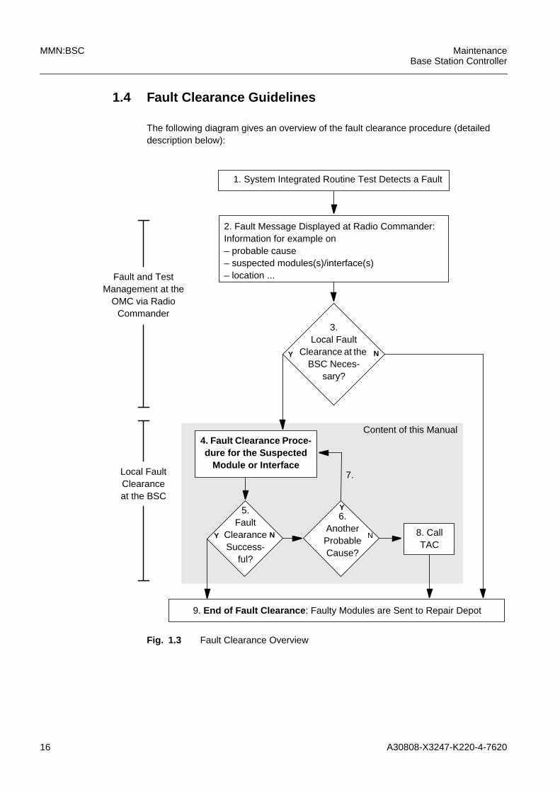
1.4 Fault Clearance Guidelines
The following diagram gives an overview of the fault clearance procedure (detaileddescription below):
Fig. 1.3 Fault Clearance Overview
7.
Y
Y6.
AnotherProbableCause?
9. End of Fault Clearance : Faulty Modules are Sent to Repair Depot
Fault and TestManagement at the
OMC via RadioCommander
N
1. System Integrated Routine Test Detects a Fault
3.Local Fault
Clearance at theBSC Neces-
sary?
Y N
2. Fault Message Displayed at Radio Commander:Information for example on– probable cause– suspected modules(s)/interface(s)– location ...
Local FaultClearanceat the BSC
4. Fault Clearance Proce-dure for the Suspected
Module or Interface
8. CallTAC
5.Fault
ClearanceSuccess-
ful?
Content of this Manual
N
A30808-X3247-K220-4-7620 17
MaintenanceBase Station Controller
MMN:BSC
Fault Clearance Guidelines
(The numbering refers to the above diagram.)
1. The system integrated routine test detects a fault.
2. A fault message is displayed at the Radio Commander.
3. The fault and test management at the Operation and Maintenance Center (OMC)must verify whether a local fault clearance at the BSC is required (see RadioCommander documentation).
4. Interpret the fault message and go to the fault clearance procedure of the suspectedmodule or interface, localize the fault and clear it according to the correspondingprocedure in chapter "3 Fault Clearance Procedures for Modules and Interfaces".
5. As described in the corresponding procedure, verify whether the fault clearance wassuccessful:
– Was the outcome of the hardware test “pass”?
– Are there any relevant pending alarms?
– Do the LEDs signal normal operation?
6. If the fault should still exist and the replaced module was not the fault cause, checkwhether there is another probable cause.
7. If there is another probable cause, reinsert the recently replaced original module andgo to the corresponding fault clearance procedure for the next suspected module orinterface.
8. It should be possible to clear most faults that may occur in the BSC by following thefault clearance procedures described in this manual. However, if the fault should stillexist after considering all probable causes, contact the Technical Assistance Center(TAC). Here you will obtain help from specially trained troubleshooting experts.
9. End of fault clearance. Pack and tag all faulty modules for transport to a repair depot.Write a fault report in which the following information is given in detail:
– name and code of the site
– BSS area, cabinet and slot number
– name, code and serial number of the module
– description of the system response
– description of the fault
– name and phone number of the originator
iFor the local fault clearance at the BSC:Make sure that all spare parts that might be required to clear the fault are availableat the site.For general module replacement instructions see also "1.5 Module ReplacementInstructions".
18 A30808-X3247-K220-4-7620
MMN:BSC MaintenanceBase Station Controller
1.5 Module Replacement Instructions
1.5.1 ESD Precautions
Fig. 1.4 ESD Symbol
All modules are to be handled with extreme care as each contains a number of electro-statically sensitive components.
All integrated modules may contain electrostatically sensitive devices (ESDs). Allmodules are marked with the ESD symbol.
The following precautions are to be taken:
– Personnel should avoid wearing synthetic clothing and shoes with plastic soles, asthese foster the build-up of electrostatic charges.
– Before handling modules, personnel should be freed of electrostatic charge. For thisreason personnel should always put on a grounded wrist strap before changing amodule.
Before touching modules, printed circuits or components, the wrist strap must beconnected to the ground potential of the rack by means of a flexible lead integrating ahigh-value discharge resistor. The discharging socket in the holder of the special tool forchanging modules must be used for connecting the wrist strap to the ground potential.This holder is located on the right vertical strut of the module side of the rack. Note thatthe conducting parts of the split pin should not be touched when plugging it in (by-passing the discharge resistor).
IMPORTANT:Modules with the ESD symbol are to be handled with extreme care. Static or externalvoltage can lead to long-term damage in the modules.
In general, the printed circuits and components of the modules should not be touched.Modules should be held only by their edges.
Removed modules are to be placed in covers made of conductive plastic (provided) andthen stored or sent off in special transport boxes or cases bearing the ESD symbol.
To prevent further damage, faulty modules are to be treated with as much care as newones.
All tools, measuring devices and metal objects that come in contact with removedmodules are to be discharged to the ground potential before being used.
To summarize:
a) ESDs should not be allowed to touch electrostatically charged or chargable objects.
A30808-X3247-K220-4-7620 19
MaintenanceBase Station Controller
MMN:BSC
b) ESDs should only come in contact with high-value discharging material ("gentle"discharging), i.e. should not undergo "harsh" discharging with, for example, a metalplate.
c) ESDs should be set down on grounded surfaces only (flexible bases with agrounding connection for servicing purposes).
d) ESDs should only be transported in authorised packaging. A grounded wrist strapmust be put on before removing ESDs.
e) ESDs should not be brought near strong DC electrical fields, e.g. cathode-raytubes/monitors (safety distance at least 10 cm (3.9”)).
f) Maintenance personnel should check the discharge resistance of the wrist straps atregular intervals.
g) Even discharges that are considerably lower than the detection limit can damage ordestroy ESDs!
1.5.2 Removing and Inserting Modules
Individual fault-clearance procedures given for each fault in the relevant manual mustbe followed when changing a suspect module.
Check whether the modules contain switches, jumpers or solder straps. If so, theirsettings must be checked and corrected if necessary, following the guidelines in themanual.
Modules are to be changed with extreme care. Inappropriate handling of modules candestroy contacts or printed circuits.
The conductive wrist strap must be put on before changing a module. It must then beconnected via the flexible lead to the discharging socket in the tool holder.
a) Removing a moduleThe module can now be pulled by hand from the guide rail in the frame.
b) Inserting a module
Push the replacement module into the guide rails in the frame. Check that the modulehas been correctly inserted into the lower rail as well as into the upper.
Push back the module in the guide rails until it encounters some resistance; this is over-come by lightly pressing by hand. The module's strip connectors (module connectors)are centered on the blade contact strips in the module frame.
The faceplate of the correctly inserted module must be level with those of the adjacentmodules.

20 A30808-X3247-K220-4-7620
MMN:BSC MaintenanceBase Station Controller
1.6 Fault Management Procedure
The following list of test equipment is recommended for use in the trouble-shootingprocedures provided in this section. Make sure that equipment needed is on hand andproperly operating.
– Local Maintenance Terminal (LMT)
– Digital Multimeter - Fluke Model 8062A with Y8134 test lead kit, or equivalent; usedfor precision DC and AC measurement, requiring 4-1/2 digits.
– Antistatic wrist strap
– Miscellaneous hand tools.
Be aware of the fact that a copy of each suspected faulty module is available on the site.
A30808-X3247-K220-4-7620 21
MaintenanceBase Station Controller
MMN:BSC
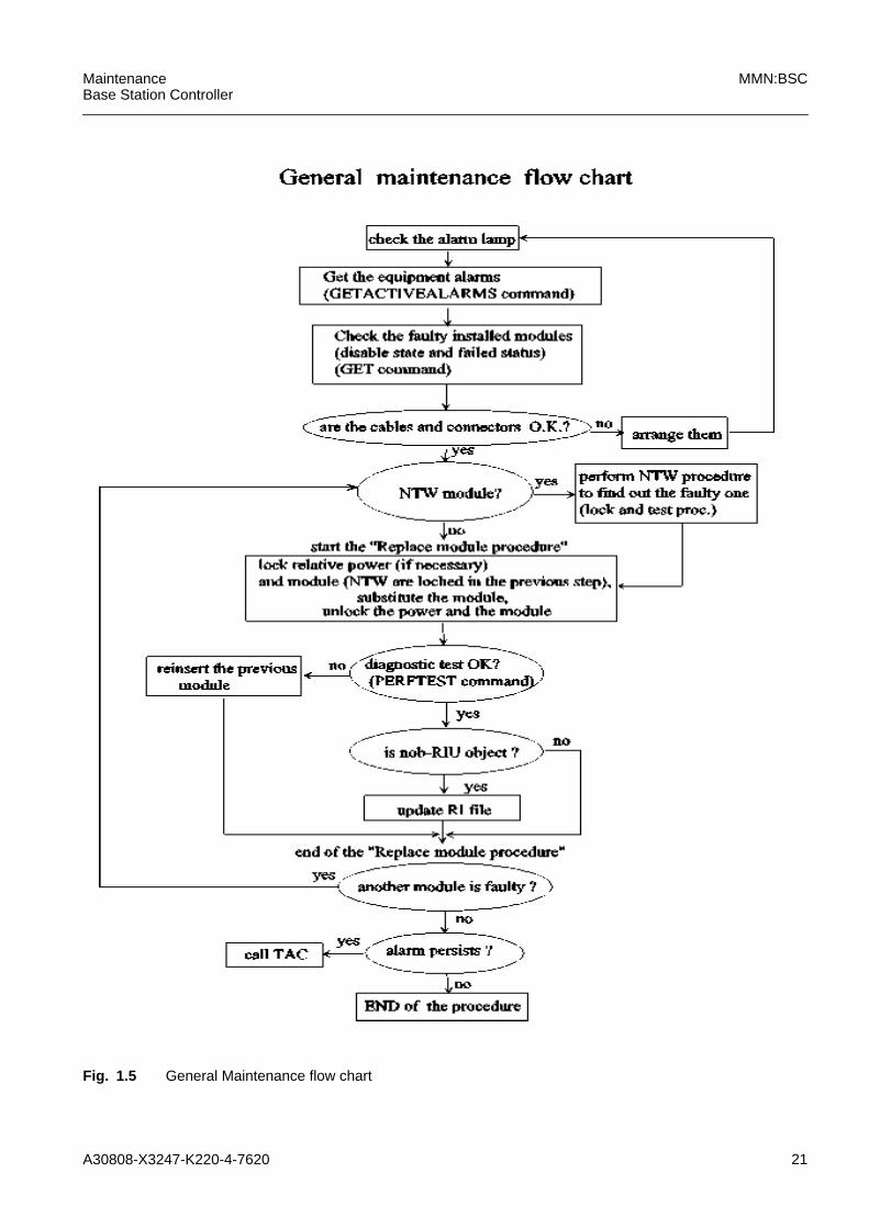
Fig. 1.5 General Maintenance flow chart

22 A30808-X3247-K220-4-7620
MMN:BSC MaintenanceBase Station Controller
In the following an explanation of the above diagram is given.
1. Test the Alarm Lamp IntegrityBefore performing any operation on the BSC rack, check for all alarm lamp integrity.Use the LAMP TEST switch located on the BSC front panel (see Hardware Equip-ment section).
2. Verify the Lamp StatusIlluminated lamps should be consistent with the suspected module signalled in theoriginal fault message.Therefore:
– the lamps on the lamp panel should signal an alarm condition; (see HardwareEquipment section)
– one or more lamps on the alarm panel should be on (see Hardware Equipmentsection)
3. Connect the LMT to the BSCPlug the LMT cable into the corresponding socket.Perform the LOGON procedure (see OGL:LMT).The LMT tree is now displayed on the screen.
4. Get the Equipment Alarms
The LMT shows the list of all the modules (possibly faulty modules) which issued anEquipment Failure Event; for each of them keep track of the related possible causeof fault.
iIf illuminated lamps are not consistent with the suspectedmodule signalled in the original fault message, this can dependon new alarms that occured after the first report. If no lamps areilluminated and an error condition is still present, the componentACKT of DK40 copy 0 (or the DK40 itself) which is responsiblefor the control of the alarm LEDs may be faulty. In this case,continue with the procedure described below. Only the equip-ment alarm lamps are relevant for the maintenance purposes.See section Hardware Equipment and section Alarm Reportingfor details about the meaning of the BSC rack lamps.
LMT tree: MANAGED-ELEMENT--> BSS-EQUIPMENT--> BSCE
Command: GATACTIVEALARMS BSCE
Name: BSCE:<instance>
Attributes: EVTYP = EQUIPMENT_FAILURE_EVENT
Submit
GATACTIVEALARMSBSCE:NAME=BSCE:<instance>,EVTYP=EQUIPMENT_FAILURE _EVENT;

A30808-X3247-K220-4-7620 23
MaintenanceBase Station Controller
MMN:BSC
5. Check the Possible Faulty ModulesFor all the possible faulty modules (from previous step), do the following from LMT:
GET <Module> STAT:NAME=<Module>:<Instance>Specify the module type by selecting it from the list. The LMT requests for the copynumber (<instance>) of the selected object. Do this operation for all the copies of thespecified module existing inside the rack (see OMN:BSC).
The LMT shows the state of each specified module. Keep track of the operationalstate and the availability status for each module.
6. Find the Suspected moduleKeeping in mind the output described above, take into account the modules forwhich:the OPERATIONAL STATE is DISABLEDthe PROBABLE CAUSE description includes the word Hardware in the Alarm EventListthe AVAILABILITY STATUS is FAILED .These modules are called “suspected modules”.
7. Replace the Suspected ModulesThe BSC rack is protected by a front cover. This must be removed in order to accessthe modules. To do this, remove the screws on the cover.
To remove a module, pull the levers on the module itself - pull up the top levers andpull down the bottom ones - then extract the module. To restore a removed moduleto its site, insert the module then push the levers - push down the top levers andpush up the bottom ones.
If the alarm originates from Line Interface Card (LICD) as QTLP, and the alarm is“LOSS OF SIGNAL” or “LOSS OF SIGNAL ON LINK A/B”, in detail “signal absent(LOS)”, LFA alarm present”, “eer alarm present (BER)”, “RAI alarm present”, checkthe jumpers on the faulty card are conforming the line impedence requirement (see"4.8 Jumpers setting") ; check also that the cable connector concerning the linenumber in failure state is correctly inserted and not damaged (see IMN:BSCmanual).These alarm conditions are shown by LINE/HWI led in the Lamp Alarm Panel andon the QTLP front led as the table of Fig. 4.34. If the alarm originates from InterfaceIXLT as “Communication Failure Event”, check the X25 cable connector (W3 on thetop rack) is correctly inserted and not damaged.
LMT tree: MANAGED-ELEMENT--> BSS-EQUIPMENT--> BSCE--> <Module>
Command: GET <Module> STAT
Name: <Module>:<instance>
Attributes: None
Submit
GET <Module> STAT:NAME=<Module>:<instance>;
24 A30808-X3247-K220-4-7620
MMN:BSC MaintenanceBase Station Controller
After a check of cables and connectors, proceede with the replace of the suspectedmodules following the procedures described in the chapter 3.
1.7 Procedures references
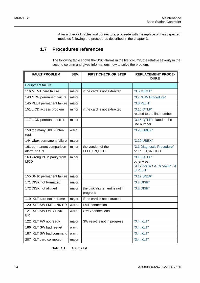
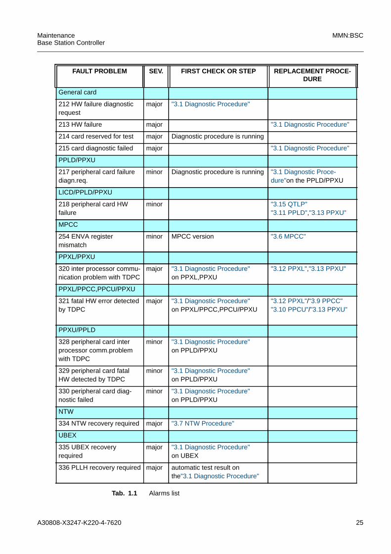
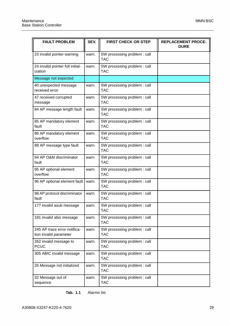
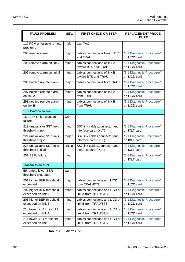
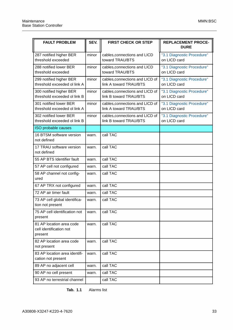
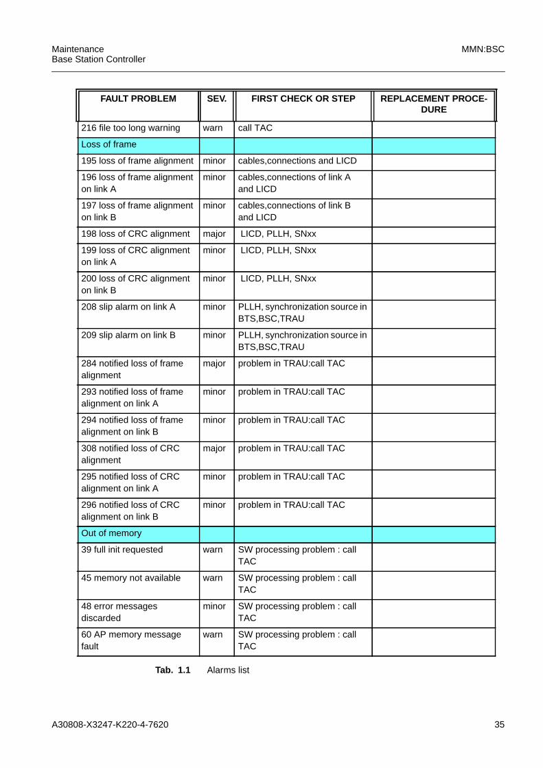
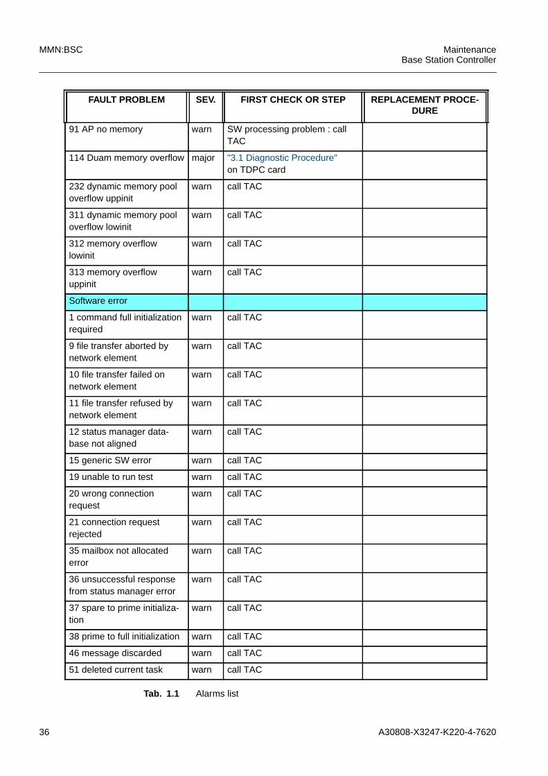
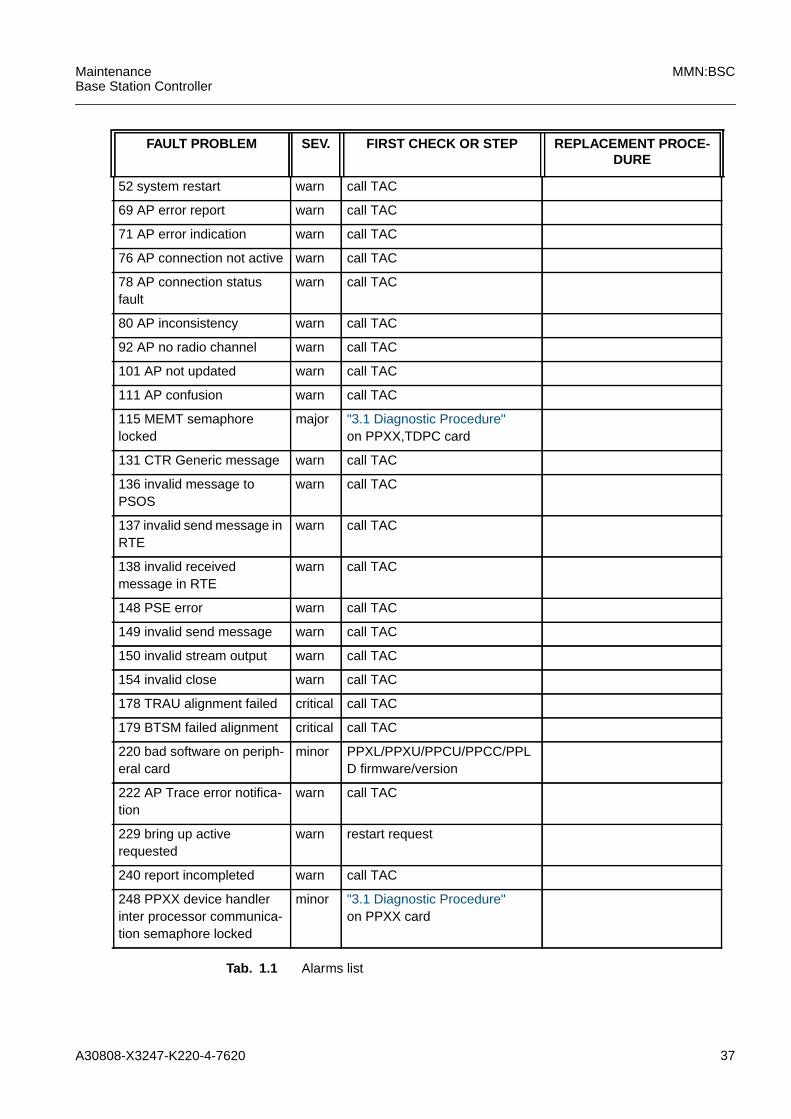
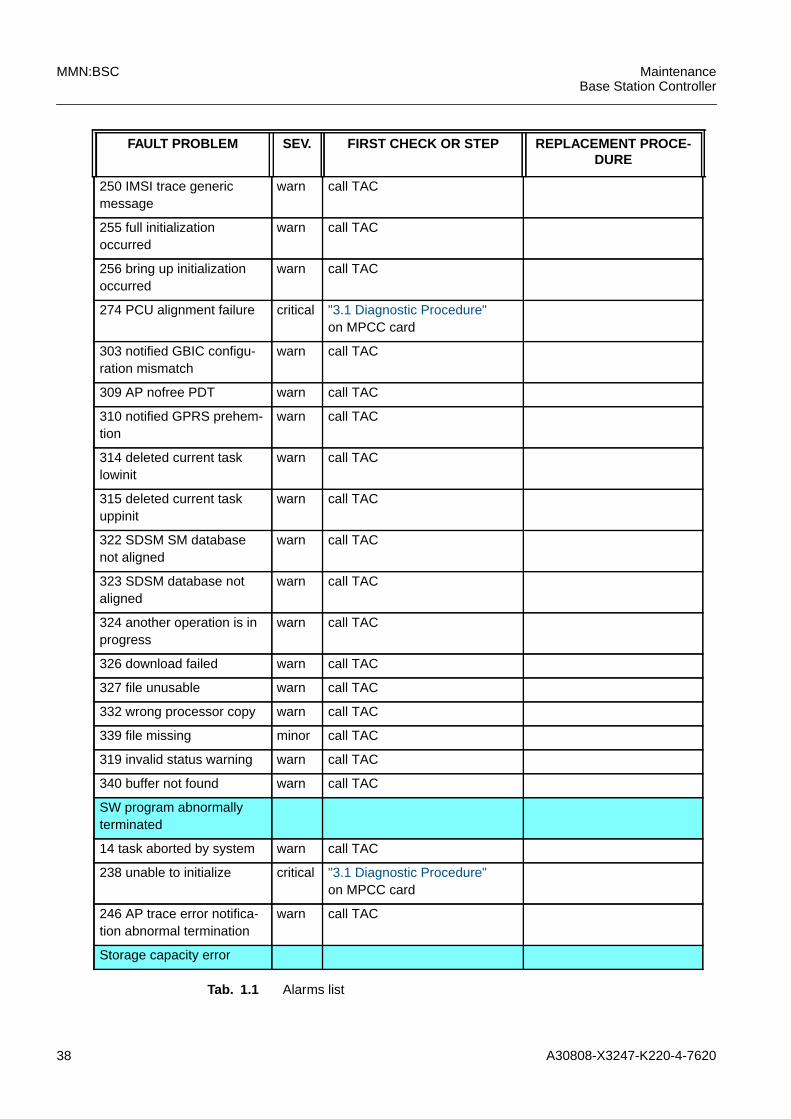
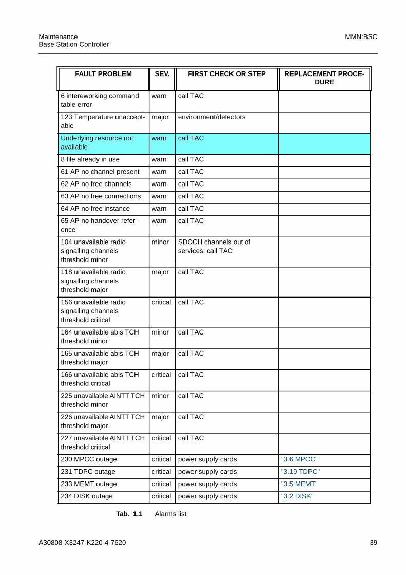
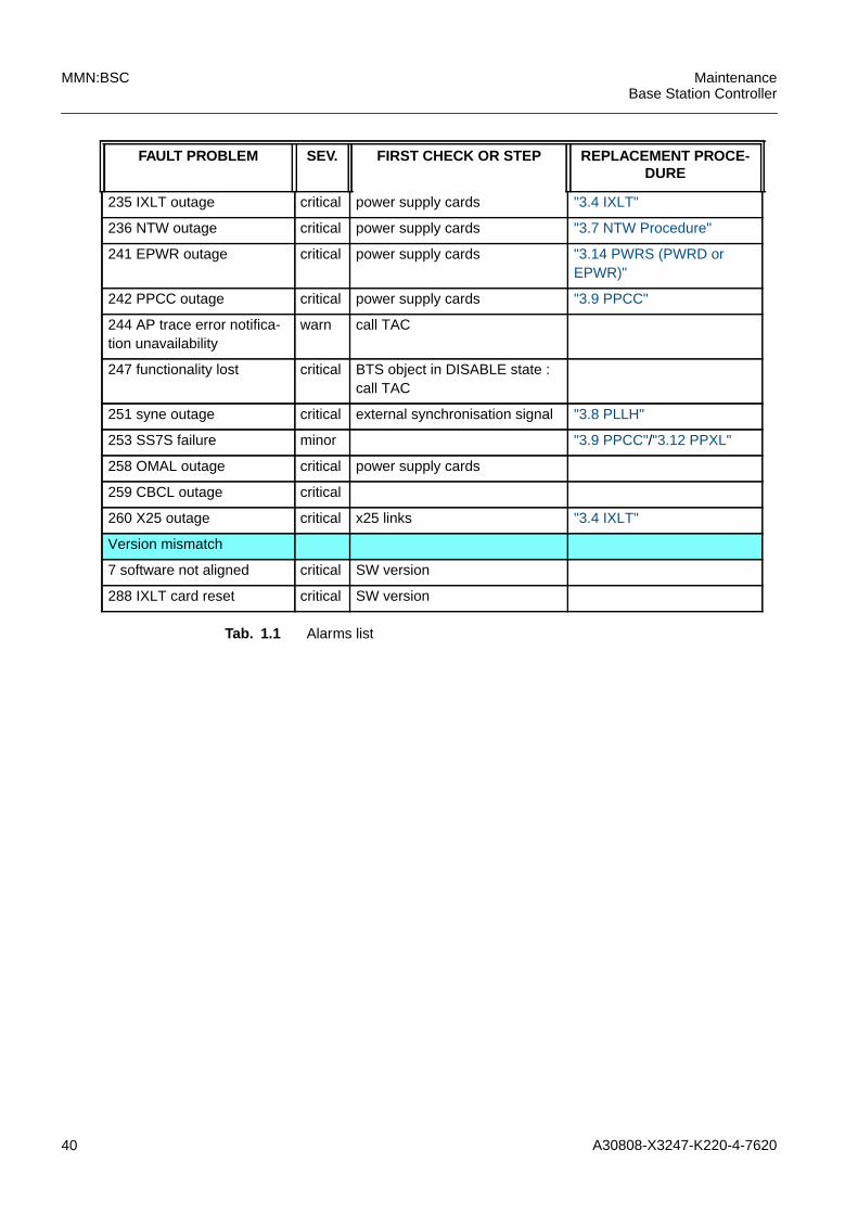
The following table shows the BSC alarms in the first column, the relative severity in thesecond column and gives informations how to solve the problem.
FAULT PROBLEM SEV. FIRST CHECK OR STEP REPLACEMENT PROCE-DURE
Equipment failure
116 MEMT card failure major if the card is not extracted "3.5 MEMT"
143 NTW permanent failure major "3.7 NTW Procedure"
145 PLLH permanent failure major "3.8 PLLH"
151 LICD access problem minor if the card is not extracted "3.15 QTLP"related to the line number
117 LICD permanent error minor "3.15 QTLP"related to theline number
158 too many UBEX inter-rupt
warn. "3.20 UBEX"
144 Ubex permanent failure major "3.20 UBEX"
161 permanent comparisonalarm on SN
minor the version of thePLLH,SN,LICD
"3.1 Diagnostic Procedure"on PLLH,SN,LICD
163 wrong PCM parity fromLICD
minor "3.15 QTLP"otherwise"3.17 SN16"/"3.18 SNAP","3.8 PLLH"
155 SN16 permanent failure major "3.17 SN16"
171 DISK not formatted major "3.2 DISK"
172 DISK not aligned major the disk alignement is not inprogress
"3.2 DISK"
119 IXLT card not in frame major if the card is not extracted
120 IXLT SW LMT LINK ER warn. LMT connection
121 IXLT SW OMC LINKER
warn. OMC connections
122 IXLT FW not ready major SW reset is not in progress "3.4 IXLT"
186 IXLT SW bad restart warn. "3.4 IXLT"
187 IXLT SW bad command warn. "3.4 IXLT"
207 IXLT card corrupted major "3.4 IXLT"
Tab. 1.1 Alarms list
A30808-X3247-K220-4-7620 25
MaintenanceBase Station Controller
MMN:BSC
General card
212 HW failure diagnosticrequest
major "3.1 Diagnostic Procedure"
213 HW failure major "3.1 Diagnostic Procedure"
214 card reserved for test major Diagnostic procedure is running
215 card diagnostic failed major "3.1 Diagnostic Procedure"
PPLD/PPXU
217 peripheral card failurediagn.req.
minor Diagnostic procedure is running "3.1 Diagnostic Proce-dure"on the PPLD/PPXU
LICD/PPLD/PPXU
218 peripheral card HWfailure
minor "3.15 QTLP""3.11 PPLD","3.13 PPXU"
MPCC
254 ENVA registermismatch
minor MPCC version "3.6 MPCC"
PPXL/PPXU
320 inter processor commu-nication problem with TDPC
major "3.1 Diagnostic Procedure"on PPXL,PPXU
"3.12 PPXL","3.13 PPXU"
PPXL/PPCC,PPCU/PPXU
321 fatal HW error detectedby TDPC
major "3.1 Diagnostic Procedure"on PPXL/PPCC,PPCU/PPXU
"3.12 PPXL"/"3.9 PPCC""3.10 PPCU"/"3.13 PPXU"
PPXU/PPLD
328 peripheral card interprocessor comm.problemwith TDPC
minor "3.1 Diagnostic Procedure"on PPLD/PPXU
329 peripheral card fatalHW detected by TDPC
minor "3.1 Diagnostic Procedure"on PPLD/PPXU
330 peripheral card diag-nostic failed
minor "3.1 Diagnostic Procedure"on PPLD/PPXU
NTW
334 NTW recovery required major "3.7 NTW Procedure"
UBEX
335 UBEX recoveryrequired
major "3.1 Diagnostic Procedure"on UBEX
336 PLLH recovery required major automatic test result onthe"3.1 Diagnostic Procedure"
FAULT PROBLEM SEV. FIRST CHECK OR STEP REPLACEMENT PROCE-DURE
Tab. 1.1 Alarms list
26 A30808-X3247-K220-4-7620
MMN:BSC MaintenanceBase Station Controller
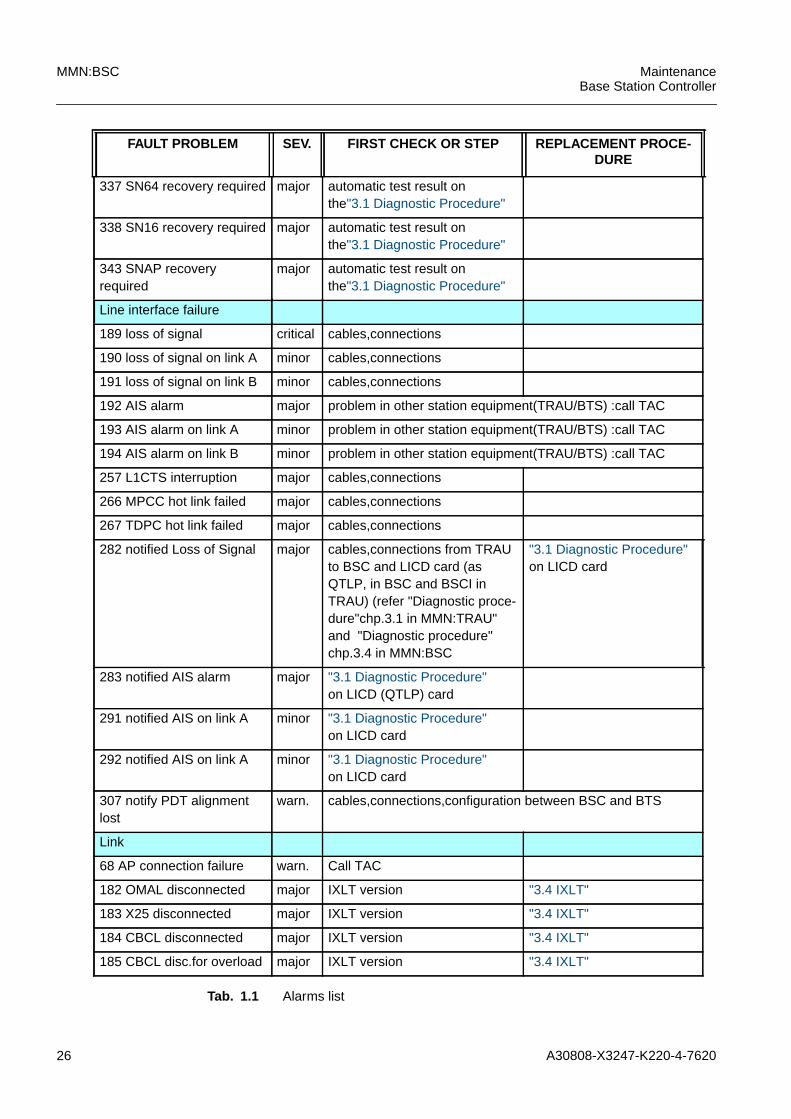
337 SN64 recovery required major automatic test result onthe"3.1 Diagnostic Procedure"
338 SN16 recovery required major automatic test result onthe"3.1 Diagnostic Procedure"
343 SNAP recoveryrequired
major automatic test result onthe"3.1 Diagnostic Procedure"
Line interface failure
189 loss of signal critical cables,connections
190 loss of signal on link A minor cables,connections
191 loss of signal on link B minor cables,connections
192 AIS alarm major problem in other station equipment(TRAU/BTS) :call TAC
193 AIS alarm on link A minor problem in other station equipment(TRAU/BTS) :call TAC
194 AIS alarm on link B minor problem in other station equipment(TRAU/BTS) :call TAC
257 L1CTS interruption major cables,connections
266 MPCC hot link failed major cables,connections
267 TDPC hot link failed major cables,connections
282 notified Loss of Signal major cables,connections from TRAUto BSC and LICD card (asQTLP, in BSC and BSCI inTRAU) (refer "Diagnostic proce-dure"chp.3.1 in MMN:TRAU"and "Diagnostic procedure"chp.3.4 in MMN:BSC
"3.1 Diagnostic Procedure"on LICD card
283 notified AIS alarm major "3.1 Diagnostic Procedure"on LICD (QTLP) card
291 notified AIS on link A minor "3.1 Diagnostic Procedure"on LICD card
292 notified AIS on link A minor "3.1 Diagnostic Procedure"on LICD card
307 notify PDT alignmentlost
warn. cables,connections,configuration between BSC and BTS
Link
68 AP connection failure warn. Call TAC
182 OMAL disconnected major IXLT version "3.4 IXLT"
183 X25 disconnected major IXLT version "3.4 IXLT"
184 CBCL disconnected major IXLT version "3.4 IXLT"
185 CBCL disc.for overload major IXLT version "3.4 IXLT"
FAULT PROBLEM SEV. FIRST CHECK OR STEP REPLACEMENT PROCE-DURE
Tab. 1.1 Alarms list
A30808-X3247-K220-4-7620 27
MaintenanceBase Station Controller
MMN:BSC
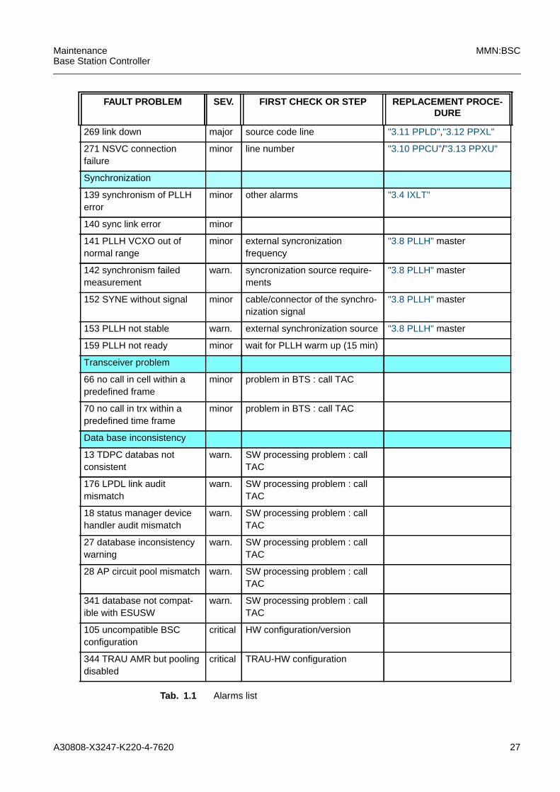
269 link down major source code line "3.11 PPLD","3.12 PPXL"
271 NSVC connectionfailure
minor line number "3.10 PPCU"/"3.13 PPXU"
Synchronization
139 synchronism of PLLHerror
minor other alarms "3.4 IXLT"
140 sync link error minor
141 PLLH VCXO out ofnormal range
minor external syncronizationfrequency
"3.8 PLLH" master
142 synchronism failedmeasurement
warn. syncronization source require-ments
"3.8 PLLH" master
152 SYNE without signal minor cable/connector of the synchro-nization signal
"3.8 PLLH" master
153 PLLH not stable warn. external synchronization source "3.8 PLLH" master
159 PLLH not ready minor wait for PLLH warm up (15 min)
Transceiver problem
66 no call in cell within apredefined frame
minor problem in BTS : call TAC
70 no call in trx within apredefined time frame
minor problem in BTS : call TAC
Data base inconsistency
13 TDPC databas notconsistent
warn. SW processing problem : callTAC
176 LPDL link auditmismatch
warn. SW processing problem : callTAC
18 status manager devicehandler audit mismatch
warn. SW processing problem : callTAC
27 database inconsistencywarning
warn. SW processing problem : callTAC
28 AP circuit pool mismatch warn. SW processing problem : callTAC
341 database not compat-ible with ESUSW
warn. SW processing problem : callTAC
105 uncompatible BSCconfiguration
critical HW configuration/version
344 TRAU AMR but poolingdisabled
critical TRAU-HW configuration
FAULT PROBLEM SEV. FIRST CHECK OR STEP REPLACEMENT PROCE-DURE
Tab. 1.1 Alarms list
28 A30808-X3247-K220-4-7620
MMN:BSC MaintenanceBase Station Controller
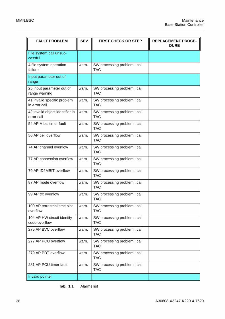
File system call unsuc-cessful
4 file system operationfailure
warn. SW processing problem : callTAC
Input parameter out ofrange
25 input parameter out ofrange warning
warn. SW processing problem : callTAC
41 invalid specific problemin error call
warn. SW processing problem : callTAC
42 invalid object identifier inerror call
warn. SW processing problem : callTAC
54 AP A-bis timer fault warn. SW processing problem : callTAC
56 AP cell overflow warn. SW processing problem : callTAC
74 AP channel overflow warn. SW processing problem : callTAC
77 AP connection overflow warn. SW processing problem : callTAC
79 AP ID2MBIT overflow warn. SW processing problem : callTAC
87 AP mode overflow warn. SW processing problem : callTAC
99 AP trx overflow warn. SW processing problem : callTAC
100 AP terrestrial time slotoverflow
warn. SW processing problem : callTAC
104 AP HW circuit identitycode overflow
warn. SW processing problem : callTAC
275 AP BVC overflow warn. SW processing problem : callTAC
277 AP PCU overflow warn. SW processing problem : callTAC
279 AP PDT overflow warn. SW processing problem : callTAC
281 AP PCU timer fault warn. SW processing problem : callTAC
Invalid pointer
FAULT PROBLEM SEV. FIRST CHECK OR STEP REPLACEMENT PROCE-DURE
Tab. 1.1 Alarms list
A30808-X3247-K220-4-7620 29
MaintenanceBase Station Controller
MMN:BSC
23 invalid pointer warning warn. SW processing problem : callTAC
24 invalid pointer full initial-ization
warn. SW processing problem : callTAC
Message not expected
40 unexpected messagereceived error
warn. SW processing problem : callTAC
47 received corruptedmessage
warn. SW processing problem : callTAC
84 AP message length fault warn. SW processing problem : callTAC
85 AP mandatory elementfault
warn. SW processing problem : callTAC
86 AP mandatory elementoverflow
warn. SW processing problem : callTAC
88 AP message type fault warn. SW processing problem : callTAC
94 AP O&M discriminatorfault
warn. SW processing problem : callTAC
95 AP optional elementoverflow
warn. SW processing problem : callTAC
96 AP optional element fault warn. SW processing problem : callTAC
98 AP protocol discriminatorfault
warn. SW processing problem : callTAC
177 invalid asub message warn. SW processing problem : callTAC
181 invalid abis message warn. SW processing problem : callTAC
245 AP trace error notifica-tion invalid parameter
warn. SW processing problem : callTAC
262 invalid message toPCUC
warn. SW processing problem : callTAC
305 ABIC invalid message warn. SW processing problem : callTAC
26 Message not initialized warn. SW processing problem : callTAC
32 Message out ofsequence
warn. SW processing problem : callTAC
FAULT PROBLEM SEV. FIRST CHECK OR STEP REPLACEMENT PROCE-DURE
Tab. 1.1 Alarms list

30 A30808-X3247-K220-4-7620
MMN:BSC MaintenanceBase Station Controller
System call unsuccessful
2 databasa backup failed warn. SW processing problem : callTAC
3 function call unsuccessful warn. SW processing problem : callTAC
29 system call unsuc-cessful warning
warn. SW processing problem : callTAC
30 system call unsuc-cessful prime task init
warn. SW processing problem : callTAC
31 system call unsuc-cessful full init
warn. SW processing problem : callTAC
34 command rejectedwarning
warn. SW processing problem : callTAC
53 inaccessible DUAM error warn. SW processing problem : callTAC
33 Timeout expired warn. SW processing problem : callTAC
22 Variable out of range warn. SW processing problem : callTAC
Cooling system failure see “Environmental failureevent”
External equipment failure
134 operator defined alarm major operator defined alarms
External power supplyfailure
133 main power supplyalarm
major power supply units
Environmental failure event
125 air conditioning equip-ment alarm
major air temperature/detectors
128 Smoke detected major environment/detectors
18 fire detected critical environment/detectors
22 humidity unacceptable major environment/detectors
129 Intrusion detected major environment/detectors
External transmissiondevice failure
FAULT PROBLEM SEV. FIRST CHECK OR STEP REPLACEMENT PROCE-DURE
Tab. 1.1 Alarms list

A30808-X3247-K220-4-7620 31
MaintenanceBase Station Controller
MMN:BSC
130 transmission equipmentalarm
major "3.1 Diagnostic Procedure" onLICD
System resource overload
132 CTR overload warn. Call TAC
188 MSC overload detected critical Call TAC
223 AP trace TDPC over-load
major Call TAC
243 BTS overload detected critical Call TAC
249 BSC overload detected critical Call TAC
Broadcast channel failure
113 BTS no BCCH available critical Call TAC
167 BCCH outage critical Call TAC
Invalid message received
108 invalid message toABIS/ASUB
warn. Call TAC
109 invalid message fromABIS/ASUB
warn. Call TAC
263 invalid message fromPCUC
warn. Call TAC
265 invalid readingmessage
warn. Call TAC
268 BSSGP invalidmessage
warn. Call TAC
Invalid MSU received
106 SCCP invalid MSUreceived
warn. wrong parameters received :callTAC
168 invalid MSU received warn. wrong parameters received :callTAC
Lapd link protocol failure
174 LPDL link unstable critical cables,connections towardsTRAU
175 LPDL link transition warn. Call TAC
331 BTSM unstable align-ment
critical cables,connections towardsBTSM
107 Routing failure warn. Call TAC
Remote alarm indicator
FAULT PROBLEM SEV. FIRST CHECK OR STEP REPLACEMENT PROCE-DURE
Tab. 1.1 Alarms list
32 A30808-X3247-K220-4-7620
MMN:BSC MaintenanceBase Station Controller
112 PCM unvailable remoteproblems
major Call TAC
204 remote alarm major cables,connections toward BTSand TRAU
"3.1 Diagnostic Procedure"on LICD card
205 remote alarm on link A minor cables,connections of link Atoward BTS and TRAU
"3.1 Diagnostic Procedure"on LICD card
206 remote alarm on link B minor cables,connections of link Btoward BTS and TRAU
"3.1 Diagnostic Procedure"on LICD card
286 notified remote alarm major cables,connections from TRAU "3.1 Diagnostic Procedure"on LICD card
297 notified remote alarmon link A
minor cables,connections of link Afrom TRAU
"3.1 Diagnostic Procedure"on LICD card
298 notified remote alarmon link B
minor cables,connections of link Bfrom TRAU
"3.1 Diagnostic Procedure"on LICD card
SS7 Protocol failure
169 SS7 Link activationfailure
warn.
219 unavailable SS7 linksthreshold minor
minor SS7 link cables,connector andinterface card (IXLT)
"3.1 Diagnostic Procedure"on IXLT card
221 unavailable SS7 linksthreshold major
major SS7 link cables,connector andinterface card (IXLT)
"3.1 Diagnostic Procedure"on IXLT card
224 unavailable SS7 linksthreshold critical
critical SS7 link cables,connector andinterface card (IXLT)
"3.1 Diagnostic Procedure"on IXLT card
252 SS7L failure minor "3.1 Diagnostic Procedure"on IXLT card
Transmission error
59 remote lower BERthreshold exceeded
warn.
201 higher BER thresholdexceeded
major cables,connections and LICDfrom TRAU/BTS
"3.1 Diagnostic Procedure"on LICD card
202 higher BER thresholdexceeded on link A
minor cables,connections and LICD oflink A from TRAU/BTS
"3.1 Diagnostic Procedure"on LICD card
203 higher BER thresholdexceeded on link B
minor cables,connections and LICD oflink B from TRAU/BTS
"3.1 Diagnostic Procedure"on LICD card
210 lower BER thresholdexceeded on link A
minor cables,connections and LICD oflink A from TRAU/BTS
"3.1 Diagnostic Procedure"on LICD card
211 lower BER thresholdexceeded on link B
minor cables,connections and LICD oflink B from TRAU/BTS
"3.1 Diagnostic Procedure"on LICD card
FAULT PROBLEM SEV. FIRST CHECK OR STEP REPLACEMENT PROCE-DURE
Tab. 1.1 Alarms list
A30808-X3247-K220-4-7620 33
MaintenanceBase Station Controller
MMN:BSC
287 notified higher BERthreshold exceeded
minor cables,connections and LICDtoward TRAU/BTS
"3.1 Diagnostic Procedure"on LICD card
288 notified lower BERthreshold exceeded
minor cables,connections and LICDtoward TRAU/BTS
"3.1 Diagnostic Procedure"on LICD card
299 notified higher BERthreshold exceeded ol link A
minor cables,connections and LICD oflink A toward TRAU/BTS
"3.1 Diagnostic Procedure"on LICD card
300 notified higher BERthreshold exceeded ol link B
minor cables,connections and LICD oflink B toward TRAU/BTS
"3.1 Diagnostic Procedure"on LICD card
301 notified lower BERthreshold exceeded ol link A
minor cables,connections and LICD oflink A toward TRAU/BTS
"3.1 Diagnostic Procedure"on LICD card
302 notified lower BERthreshold exceeded ol link B
minor cables,connections and LICD oflink B toward TRAU/BTS
"3.1 Diagnostic Procedure"on LICD card
ISO probable causes
16 BTSM software versionnot defined
warn. call TAC
17 TRAU software versionnot defined
warn. call TAC
55 AP BTS Identifier fault warn. call TAC
57 AP cell not configured warn. call TAC
58 AP channel not config-ured
warn. call TAC
67 AP TRX not configured warn. call TAC
72 AP air timer fault warn. call TAC
73 AP cell global identifica-tion not present
warn. call TAC
75 AP cell identification notpresent
warn. call TAC
81 AP location area codecell identification notpresent
warn. call TAC
82 AP location area codenot present
warn. call TAC
83 AP location area identifi-cation not present
warn. call TAC
89 AP no adjacent cell warn. call TAC
90 AP no cell present warn. call TAC
93 AP no terrestrial channel call TAC
FAULT PROBLEM SEV. FIRST CHECK OR STEP REPLACEMENT PROCE-DURE
Tab. 1.1 Alarms list

34 A30808-X3247-K220-4-7620
MMN:BSC MaintenanceBase Station Controller
103 AP HW circuit identitycode not configured
warn. call TAC
110 unespected LPDLestablished
warn. call TAC
135 AP BTS without allBBSIG44 CARDS
warn. call TAC
157 Invalid type of SN major SNxx type/version
160 invalid type of PLLH minor PLLL version
162 Invalid type of LICD minor LICD type/version
270 configuration mismatch minor line configuration call TAC
276 AP BVC not configured warn. card not equipped : call TAC
278 AP PCU not configured warn. card not equipped : call TAC
280 AP PDT not configured warn. card not equipped : call TAC
3067 AP routing area codenot present
call TAC
Congestion
43 start throttling error minor error collector on MPCC/TDPCtoo busy :call TAC
273 overflow of commandstables
warn. call TAC
Corrupt data
147 invalid message to RTE warn call TAC
5 check on file contentsfailed
warn wrong format file :call TAC
264 invalid access to data warn logical_PPXX table corrupted "3.1 Diagnostic Procedure"on PPXXD card
304 Invalid message length warn call TAC
308 invalid destinationmailbox
warn call TAC
333 memory buffercorrupted
warn "3.1 Diagnostic Procedure"on MEMT card
345 invalid DUAM index warn "3.1 Diagnostic Procedure"on PPXX,TDPC card
127 Enclosure door open minor door/open sensor
File error
170 error in prepairing file warn call TAC
FAULT PROBLEM SEV. FIRST CHECK OR STEP REPLACEMENT PROCE-DURE
Tab. 1.1 Alarms list
A30808-X3247-K220-4-7620 35
MaintenanceBase Station Controller
MMN:BSC
216 file too long warning warn call TAC
Loss of frame
195 loss of frame alignment minor cables,connections and LICD
196 loss of frame alignmenton link A
minor cables,connections of link Aand LICD
197 loss of frame alignmenton link B
minor cables,connections of link Band LICD
198 loss of CRC alignment major LICD, PLLH, SNxx
199 loss of CRC alignmenton link A
minor LICD, PLLH, SNxx
200 loss of CRC alignmenton link B
minor LICD, PLLH, SNxx
208 slip alarm on link A minor PLLH, synchronization source inBTS,BSC,TRAU
209 slip alarm on link B minor PLLH, synchronization source inBTS,BSC,TRAU
284 notified loss of framealignment
major problem in TRAU:call TAC
293 notified loss of framealignment on link A
minor problem in TRAU:call TAC
294 notified loss of framealignment on link B
minor problem in TRAU:call TAC
308 notified loss of CRCalignment
major problem in TRAU:call TAC
295 notified loss of CRCalignment on link A
minor problem in TRAU:call TAC
296 notified loss of CRCalignment on link B
minor problem in TRAU:call TAC
Out of memory
39 full init requested warn SW processing problem : callTAC
45 memory not available warn SW processing problem : callTAC
48 error messagesdiscarded
minor SW processing problem : callTAC
60 AP memory messagefault
warn SW processing problem : callTAC
FAULT PROBLEM SEV. FIRST CHECK OR STEP REPLACEMENT PROCE-DURE
Tab. 1.1 Alarms list
36 A30808-X3247-K220-4-7620
MMN:BSC MaintenanceBase Station Controller
91 AP no memory warn SW processing problem : callTAC
114 Duam memory overflow major "3.1 Diagnostic Procedure"on TDPC card
232 dynamic memory pooloverflow uppinit
warn call TAC
311 dynamic memory pooloverflow lowinit
warn call TAC
312 memory overflowlowinit
warn call TAC
313 memory overflowuppinit
warn call TAC
Software error
1 command full initializationrequired
warn call TAC
9 file transfer aborted bynetwork element
warn call TAC
10 file transfer failed onnetwork element
warn call TAC
11 file transfer refused bynetwork element
warn call TAC
12 status manager data-base not aligned
warn call TAC
15 generic SW error warn call TAC
19 unable to run test warn call TAC
20 wrong connectionrequest
warn call TAC
21 connection requestrejected
warn call TAC
35 mailbox not allocatederror
warn call TAC
36 unsuccessful responsefrom status manager error
warn call TAC
37 spare to prime initializa-tion
warn call TAC
38 prime to full initialization warn call TAC
46 message discarded warn call TAC
51 deleted current task warn call TAC
FAULT PROBLEM SEV. FIRST CHECK OR STEP REPLACEMENT PROCE-DURE
Tab. 1.1 Alarms list
A30808-X3247-K220-4-7620 37
MaintenanceBase Station Controller
MMN:BSC
52 system restart warn call TAC
69 AP error report warn call TAC
71 AP error indication warn call TAC
76 AP connection not active warn call TAC
78 AP connection statusfault
warn call TAC
80 AP inconsistency warn call TAC
92 AP no radio channel warn call TAC
101 AP not updated warn call TAC
111 AP confusion warn call TAC
115 MEMT semaphorelocked
major "3.1 Diagnostic Procedure"on PPXX,TDPC card
131 CTR Generic message warn call TAC
136 invalid message toPSOS
warn call TAC
137 invalid send message inRTE
warn call TAC
138 invalid receivedmessage in RTE
warn call TAC
148 PSE error warn call TAC
149 invalid send message warn call TAC
150 invalid stream output warn call TAC
154 invalid close warn call TAC
178 TRAU alignment failed critical call TAC
179 BTSM failed alignment critical call TAC
220 bad software on periph-eral card
minor PPXL/PPXU/PPCU/PPCC/PPLD firmware/version
222 AP Trace error notifica-tion
warn call TAC
229 bring up activerequested
warn restart request
240 report incompleted warn call TAC
248 PPXX device handlerinter processor communica-tion semaphore locked
minor "3.1 Diagnostic Procedure"on PPXX card
FAULT PROBLEM SEV. FIRST CHECK OR STEP REPLACEMENT PROCE-DURE
Tab. 1.1 Alarms list
38 A30808-X3247-K220-4-7620
MMN:BSC MaintenanceBase Station Controller
250 IMSI trace genericmessage
warn call TAC
255 full initializationoccurred
warn call TAC
256 bring up initializationoccurred
warn call TAC
274 PCU alignment failure critical "3.1 Diagnostic Procedure"on MPCC card
303 notified GBIC configu-ration mismatch
warn call TAC
309 AP nofree PDT warn call TAC
310 notified GPRS prehem-tion
warn call TAC
314 deleted current tasklowinit
warn call TAC
315 deleted current taskuppinit
warn call TAC
322 SDSM SM databasenot aligned
warn call TAC
323 SDSM database notaligned
warn call TAC
324 another operation is inprogress
warn call TAC
326 download failed warn call TAC
327 file unusable warn call TAC
332 wrong processor copy warn call TAC
339 file missing minor call TAC
319 invalid status warning warn call TAC
340 buffer not found warn call TAC
SW program abnormallyterminated
14 task aborted by system warn call TAC
238 unable to initialize critical "3.1 Diagnostic Procedure"on MPCC card
246 AP trace error notifica-tion abnormal termination
warn call TAC
Storage capacity error
FAULT PROBLEM SEV. FIRST CHECK OR STEP REPLACEMENT PROCE-DURE
Tab. 1.1 Alarms list
A30808-X3247-K220-4-7620 39
MaintenanceBase Station Controller
MMN:BSC
6 intereworking commandtable error
warn call TAC
123 Temperature unaccept-able
major environment/detectors
Underlying resource notavailable
warn call TAC
8 file already in use warn call TAC
61 AP no channel present warn call TAC
62 AP no free channels warn call TAC
63 AP no free connections warn call TAC
64 AP no free instance warn call TAC
65 AP no handover refer-ence
warn call TAC
104 unavailable radiosignalling channelsthreshold minor
minor SDCCH channels out ofservices: call TAC
118 unavailable radiosignalling channelsthreshold major
major call TAC
156 unavailable radiosignalling channelsthreshold critical
critical call TAC
164 unavailable abis TCHthreshold minor
minor call TAC
165 unavailable abis TCHthreshold major
major call TAC
166 unavailable abis TCHthreshold critical
critical call TAC
225 unavailable AINTT TCHthreshold minor
minor call TAC
226 unavailable AINTT TCHthreshold major
major call TAC
227 unavailable AINTT TCHthreshold critical
critical call TAC
230 MPCC outage critical power supply cards "3.6 MPCC"
231 TDPC outage critical power supply cards "3.19 TDPC"
233 MEMT outage critical power supply cards "3.5 MEMT"
234 DISK outage critical power supply cards "3.2 DISK"
FAULT PROBLEM SEV. FIRST CHECK OR STEP REPLACEMENT PROCE-DURE
Tab. 1.1 Alarms list
40 A30808-X3247-K220-4-7620
MMN:BSC MaintenanceBase Station Controller
235 IXLT outage critical power supply cards "3.4 IXLT"
236 NTW outage critical power supply cards "3.7 NTW Procedure"
241 EPWR outage critical power supply cards "3.14 PWRS (PWRD orEPWR)"
242 PPCC outage critical power supply cards "3.9 PPCC"
244 AP trace error notifica-tion unavailability
warn call TAC
247 functionality lost critical BTS object in DISABLE state :call TAC
251 syne outage critical external synchronisation signal "3.8 PLLH"
253 SS7S failure minor "3.9 PPCC"/"3.12 PPXL"
258 OMAL outage critical power supply cards
259 CBCL outage critical
260 X25 outage critical x25 links "3.4 IXLT"
Version mismatch
7 software not aligned critical SW version
288 IXLT card reset critical SW version
FAULT PROBLEM SEV. FIRST CHECK OR STEP REPLACEMENT PROCE-DURE
Tab. 1.1 Alarms list
A30808-X3247-K220-4-7620 41
MaintenanceBase Station Controller
MMN:BSC
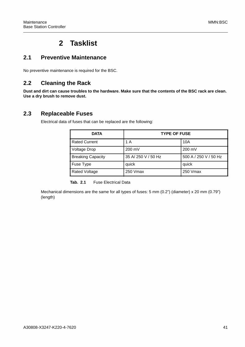
2 Tasklist
2.1 Preventive Maintenance
No preventive maintenance is required for the BSC.
2.2 Cleaning the RackDust and dirt can cause troubles to the hardware. Make sure that the contents of the BSC rack are clean.Use a dry brush to remove dust.
2.3 Replaceable FusesElectrical data of fuses that can be replaced are the following:
Mechanical dimensions are the same for all types of fuses: 5 mm (0.2”) (diameter) x 20 mm (0.79”)(length)
DATA TYPE OF FUSE
Rated Current 1 A 10A
Voltage Drop 200 mV 200 mV
Breaking Capacity 35 A/ 250 V / 50 Hz 500 A / 250 V / 50 Hz
Fuse Type quick quick
Rated Voltage 250 Vmax 250 Vmax
Tab. 2.1 Fuse Electrical Data

42 A30808-X3247-K220-4-7620
MMN:BSC MaintenanceBase Station Controller

A30808-X3247-K220-4-7620 43
MaintenanceBase Station Controller
MMN:BSC
3 Fault Clearance Procedures for Modules andInterfaces

44 A30808-X3247-K220-4-7620
MMN:BSC MaintenanceBase Station Controller
A30808-X3247-K220-4-7620 45
MaintenanceBase Station Controller
MMN:BSC
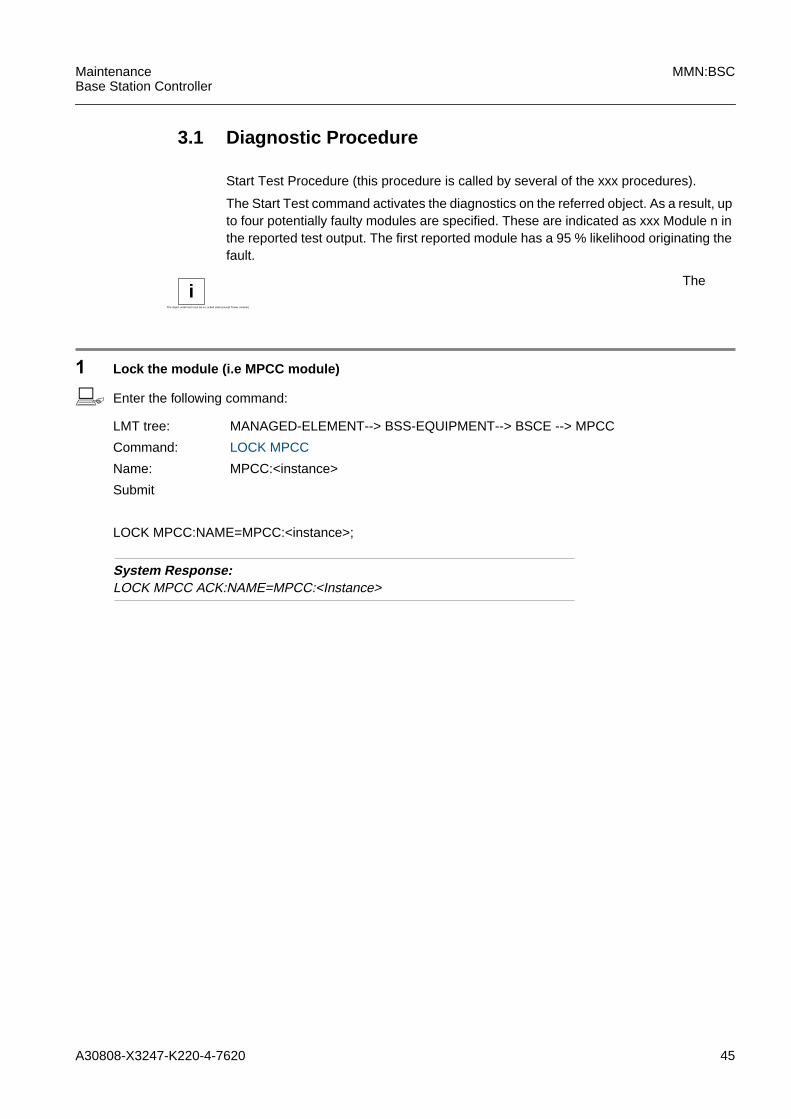
3.1 Diagnostic Procedure
Start Test Procedure (this procedure is called by several of the xxx procedures).
The Start Test command activates the diagnostics on the referred object. As a result, upto four potentially faulty modules are specified. These are indicated as xxx Module n inthe reported test output. The first reported module has a 95 % likelihood originating thefault.
1 Lock the module (i.e MPCC module)
b Enter the following command:
System Response:LOCK MPCC ACK:NAME=MPCC:<Instance>
iThe object under test must be in Locked state (except Power module)
The
LMT tree: MANAGED-ELEMENT--> BSS-EQUIPMENT--> BSCE --> MPCC
Command: LOCK MPCC
Name: MPCC:<instance>
Submit
LOCK MPCC:NAME=MPCC:<instance>;
46 A30808-X3247-K220-4-7620
MMN:BSC MaintenanceBase Station Controller
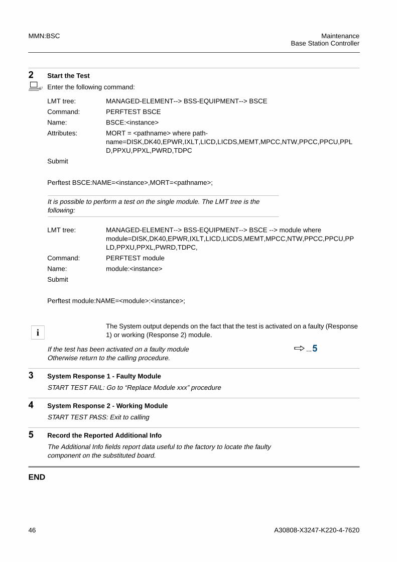
2 Start the Test
b Enter the following command:
It is possible to perform a test on the single module. The LMT tree is thefollowing:
If the test has been activated on a faulty moduleOtherwise return to the calling procedure.
h...5
3 System Response 1 - Faulty Module
START TEST FAIL: Go to “Replace Module xxx” procedure
4 System Response 2 - Working Module
START TEST PASS: Exit to calling
5 Record the Reported Additional Info
The Additional Info fields report data useful to the factory to locate the faultycomponent on the substituted board.
END
LMT tree: MANAGED-ELEMENT--> BSS-EQUIPMENT--> BSCE
Command: PERFTEST BSCE
Name: BSCE:<instance>
Attributes: MORT = <pathname> where path-name=DISK,DK40,EPWR,IXLT,LICD,LICDS,MEMT,MPCC,NTW,PPCC,PPCU,PPLD,PPXU,PPXL,PWRD,TDPC
Submit
Perftest BSCE:NAME=<instance>,MORT=<pathname>;
LMT tree: MANAGED-ELEMENT--> BSS-EQUIPMENT--> BSCE --> module wheremodule=DISK,DK40,EPWR,IXLT,LICD,LICDS,MEMT,MPCC,NTW,PPCC,PPCU,PPLD,PPXU,PPXL,PWRD,TDPC,
Command: PERFTEST module
Name: module:<instance>
Submit
Perftest module:NAME=<module>:<instance>;
iThe System output depends on the fact that the test is activated on a faulty (Response1) or working (Response 2) module.
A30808-X3247-K220-4-7620 47
MaintenanceBase Station Controller
MMN:BSC
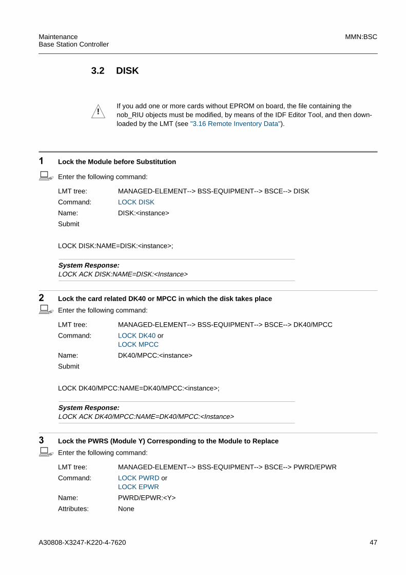
3.2 DISK
1 Lock the Module before Substitution
b Enter the following command:
System Response:LOCK ACK DISK:NAME=DISK:<Instance>
2 Lock the card related DK40 or MPCC in which the disk takes place
b Enter the following command:
System Response:LOCK ACK DK40/MPCC:NAME=DK40/MPCC:<Instance>
3 Lock the PWRS (Module Y) Corresponding to the Module to Replace
b Enter the following command:
!If you add one or more cards without EPROM on board, the file containing thenob_RIU objects must be modified, by means of the IDF Editor Tool, and then down-loaded by the LMT (see "3.16 Remote Inventory Data").
LMT tree: MANAGED-ELEMENT--> BSS-EQUIPMENT--> BSCE--> DISK
Command: LOCK DISK
Name: DISK:<instance>
Submit
LOCK DISK:NAME=DISK:<instance>;
LMT tree: MANAGED-ELEMENT--> BSS-EQUIPMENT--> BSCE--> DK40/MPCC
Command: LOCK DK40 orLOCK MPCC
Name: DK40/MPCC:<instance>
Submit
LOCK DK40/MPCC:NAME=DK40/MPCC:<instance>;
LMT tree: MANAGED-ELEMENT--> BSS-EQUIPMENT--> BSCE--> PWRD/EPWR
Command: LOCK PWRD orLOCK EPWR
Name: PWRD/EPWR:<Y>
Attributes: None

48 A30808-X3247-K220-4-7620
MMN:BSC MaintenanceBase Station Controller
System Response:LOCK ACK:NAME=PWRS:Y
4 Pull down the OFF REQ Switch on the PWRS Module Y
System Response:SYSTEMINFOREPORT:NAME=PWRS:YINFORMATION IDENTIFIER=POWER KEYLOCK SWITCH OFF
The red LED on module PWRS is switched on, if power is switched off.
5 Replace the Module
6 Pull up the OFF REQ Switch on PWRS Module Y
System Response:SYSTEM INFOREPORT:NAME=PWRS:YINFORMATIONIDENTIFIER:POWER KEYLOCK SWITCH ON
7 Unlock the PWRS (Module Y) Corresponding to the Module to Replace
b Enter the following command:
Submit
LOCK PWRD/EPWR:<Y>;
iThe modules connected to the PRWS-Y which has been switched off are put into the"disabled" state.
iIf the PWRS module Y is not in the locked state, it will not switch off.
!Follow the recommended instructions (see "1.5 Module ReplacementInstructions") and according to the rack structure (see "4 Hardware Equip-ment")
iThe modules connected to PWRS-Y (which has been switched on) remain in a"disabled dependency" state because PWRS-Y is LOCKED.
LMT tree: MANAGED-ELEMENT--> BSS-EQUIPMENT--> BSCE--> PWRD/EPWR
Command: UNLOCK PWRD orUNLOCK EPWR
Name: PWRD/EPWR:<instance>
Attributes: None
A30808-X3247-K220-4-7620 49
MaintenanceBase Station Controller
MMN:BSC
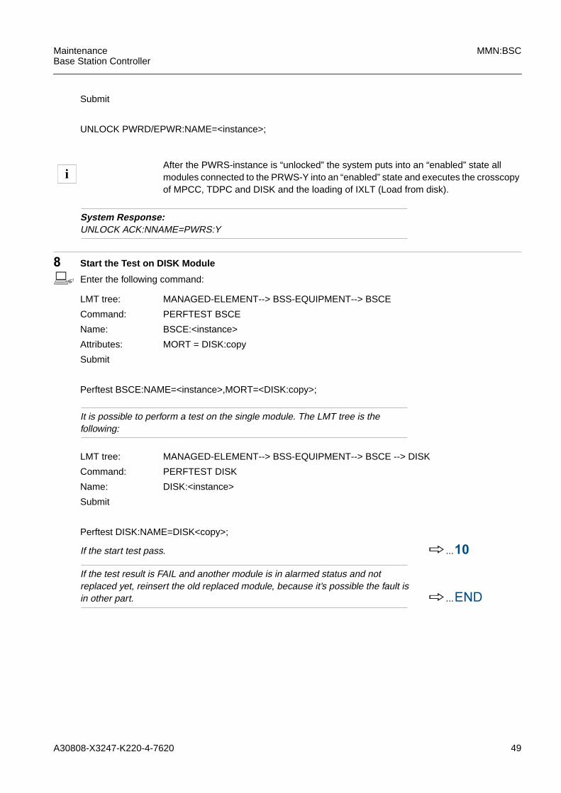
System Response:UNLOCK ACK:NNAME=PWRS:Y
8 Start the Test on DISK Module
b Enter the following command:
It is possible to perform a test on the single module. The LMT tree is thefollowing:
If the start test pass. h...10
If the test result is FAIL and another module is in alarmed status and notreplaced yet, reinsert the old replaced module, because it’s possible the fault isin other part. h...END
Submit
UNLOCK PWRD/EPWR:NAME=<instance>;
iAfter the PWRS-instance is “unlocked” the system puts into an “enabled” state allmodules connected to the PRWS-Y into an “enabled” state and executes the crosscopyof MPCC, TDPC and DISK and the loading of IXLT (Load from disk).
LMT tree: MANAGED-ELEMENT--> BSS-EQUIPMENT--> BSCE
Command: PERFTEST BSCE
Name: BSCE:<instance>
Attributes: MORT = DISK:copy
Submit
Perftest BSCE:NAME=<instance>,MORT=<DISK:copy>;
LMT tree: MANAGED-ELEMENT--> BSS-EQUIPMENT--> BSCE --> DISK
Command: PERFTEST DISK
Name: DISK:<instance>
Submit
Perftest DISK:NAME=DISK<copy>;

50 A30808-X3247-K220-4-7620
MMN:BSC MaintenanceBase Station Controller
9 Start the Test on DK40/MPCC Module
b Enter the following command:
It is possible to perform a test on the single module. The LMT tree is thefollowing:
If the start test pass. h...10
If the test result is FAIL and another module is in alarmed status and notreplaced yet, reinsert the old replaced module, because it’s possible the fault isin other part. h...END
10 Unlock the DISK
b Enter the following command:
System Response:UNLOCK ACK DISK:NAME=DISK:<Instance>
Result:The hard disk is formatted, crosscopied and unlocked automatically by thesystem.
LMT tree: MANAGED-ELEMENT--> BSS-EQUIPMENT--> BSCE
Command: PERFTEST BSCE
Name: BSCE:<instance>
Attributes: MORT = DK40/MPCC:copy
Submit
Perftest BSCE:NAME=<instance>,MORT=<DK40/MPCC:copy>;
LMT tree: MANAGED-ELEMENT--> BSS-EQUIPMENT--> BSCE --> DK40/MPCC
Command: PERFTEST DK40/MPCC
Name: DK40/MPCC:<instance>
Submit
Perftest DK40/MPCC:NAME=DK40/MPCC<copy>;
LMT tree: MANAGED-ELEMENT--> BSS-EQUIPMENT--> BSCE--> DISK
Command: UNLOCK DISK
Name: DISK:<instance>
Attributes: None
Submit
UNLOCK DISK:NAME=DISK:<instance>;

A30808-X3247-K220-4-7620 51
MaintenanceBase Station Controller
MMN:BSC
11 Unlock the DK40/MPCC
b Enter the following command:
System Response:UNLOCK ACK DK40/MPCC:NAME=DK40/MPCC:<Instance>
Result:The hard DK40/MPCC is formatted, crosscopied and unlocked automatically bythe system.
12 Update the RI file
Edit the RI-data by the IDF Editor Tool , update the Nob_Riu object file, exportand then download into BSC. h... "3.16 Remote
Inventory Data"
END. Return to the calling procedure.
LMT tree: MANAGED-ELEMENT--> BSS-EQUIPMENT--> BSCE--> DK40/MPCC
Command: UNLOCK DISK
Name: DK40/MPCC:<instance>
Attributes: None
Submit
UNLOCK DK40/MPCC:NAME=DK40/MPCC:<instance>;

52 A30808-X3247-K220-4-7620
MMN:BSC MaintenanceBase Station Controller
A30808-X3247-K220-4-7620 53
MaintenanceBase Station Controller
MMN:BSC
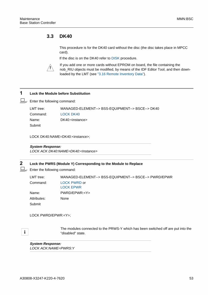
3.3 DK40
This procedure is for the DK40 card without the disc (the disc takes place in MPCCcard).
If the disc is on the DK40 refer to DISK procedure.
1 Lock the Module before Substitution
b Enter the following command:
System Response:LOCK ACK DK40:NAME=DK40:<Instance>
2 Lock the PWRS (Module Y) Corresponding to the Module to Replace
b Enter the following command:
System Response:LOCK ACK:NAME=PWRS:Y
!If you add one or more cards without EPROM on board, the file containing thenob_RIU objects must be modified, by means of the IDF Editor Tool, and then down-loaded by the LMT (see "3.16 Remote Inventory Data").
LMT tree: MANAGED-ELEMENT--> BSS-EQUIPMENT--> BSCE--> DK40
Command: LOCK DK40
Name: DK40:<instance>
Submit
LOCK DK40:NAME=DK40:<instance>;
LMT tree: MANAGED-ELEMENT--> BSS-EQUIPMENT--> BSCE--> PWRD/EPWR
Command: LOCK PWRD orLOCK EPWR
Name: PWRD/EPWR:<Y>
Attributes: None
Submit
LOCK PWRD/EPWR:<Y>;
iThe modules connected to the PRWS-Y which has been switched off are put into the"disabled" state.

54 A30808-X3247-K220-4-7620
MMN:BSC MaintenanceBase Station Controller
3 Pull down the OFF REQ Switch on the PWRS Module Y
System Response:SYSTEMINFOREPORT:NAME=PWRS:YINFORMATION IDENTIFIER=POWER KEYLOCK SWITCH OFF
The red LED on module PWRS is switched on, if power is switched off.
4 Replace the Module
5 Pull up the OFF REQ Switch on PWRS Module Y
System Response:SYSTEM INFOREPORT:NAME=PWRS:YINFORMATIONIDENTIFIER:POWER KEYLOCK SWITCH ON
6 Unlock the PWRS (Module Y) Corresponding to the Module to Replace
b Enter the following command:
System Response:UNLOCK ACK:NNAME=PWRS:Y
iIf the PWRS module Y is not in the locked state, it will not switch off.
!Follow the recommended instructions (see "1.5 Module ReplacementInstructions") and according to the rack structure (see "4 Hardware Equip-ment")
iThe modules connected to PWRS-Y (which has been switched on) remain in a"disabled dependency" state because PWRS-Y is LOCKED.
LMT tree: MANAGED-ELEMENT--> BSS-EQUIPMENT--> BSCE--> PWRD/EPWR
Command: UNLOCK PWRD orUNLOCK EPWR
Name: PWRD/EPWR:<instance>
Attributes: None
Submit
UNLOCK PWRD/EPWR:NAME=<instance>;
iAfter the PWRS-instance is “unlocked” the system puts into an “enabled” state allmodules connected to the PRWS-Y into an “enabled” state and executes the crosscopyof MPCC, TDPC and DISK and the loading of IXLT (Load from disk).
A30808-X3247-K220-4-7620 55
MaintenanceBase Station Controller
MMN:BSC
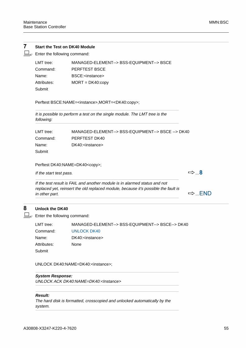
7 Start the Test on DK40 Module
b Enter the following command:
It is possible to perform a test on the single module. The LMT tree is thefollowing:
If the start test pass. h...8
If the test result is FAIL and another module is in alarmed status and notreplaced yet, reinsert the old replaced module, because it’s possible the fault isin other part. h...END
8 Unlock the DK40
b Enter the following command:
System Response:UNLOCK ACK DK40:NAME=DK40:<Instance>
Result:The hard disk is formatted, crosscopied and unlocked automatically by thesystem.
LMT tree: MANAGED-ELEMENT--> BSS-EQUIPMENT--> BSCE
Command: PERFTEST BSCE
Name: BSCE:<instance>
Attributes: MORT = DK40:copy
Submit
Perftest BSCE:NAME=<instance>,MORT=<DK40:copy>;
LMT tree: MANAGED-ELEMENT--> BSS-EQUIPMENT--> BSCE --> DK40
Command: PERFTEST DK40
Name: DK40:<instance>
Submit
Perftest DK40:NAME=DK40<copy>;
LMT tree: MANAGED-ELEMENT--> BSS-EQUIPMENT--> BSCE--> DK40
Command: UNLOCK DK40
Name: DK40:<instance>
Attributes: None
Submit
UNLOCK DK40:NAME=DK40:<instance>;

56 A30808-X3247-K220-4-7620
MMN:BSC MaintenanceBase Station Controller
9 Update the RI file
Edit the RI-data by the IDF Editor Tool , update the Nob_Riu object file, exportand then download into BSC. h..."3.16 Remote
Inventory Data"
END. Return to the calling procedure.
A30808-X3247-K220-4-7620 57
MaintenanceBase Station Controller
MMN:BSC
3.4 IXLT
1 Check the cables
2 Lock the Module before Substitution
b Enter the following command:
System Response:Lock ACK IXLT:NAME=IXLT:<Instance>
3 Lock the PWRS (Module Y) Corresponding to the Module to Replace
b Enter the following command:
!If you add one or more cards without EPROM on board, the file containing thenob_RIU objects must be modified, by means of the IDF Editor Tool, and then down-loaded by the LMT (see "3.16 Remote Inventory Data").
!If the alarm originates from Line Interface Card (LICD) as DTLP or QTLP, and thealarm is “LOSS OF SIGNAL” or “LOSS OF SIGNAL ON LINK A/B”, in detail “signalabsent (LOS)”, LFA alarm present”, “eer alarm present (BER)”, “RAI alarm present”,check the jumpers on the faulty card are conforming the line impedence requirement(see "4.8 Jumpers setting") ; check also that the cable connector concerning the linenumber in failure state is correctly inserted and not damaged (see IMN:BSC manual).These alarm conditions are shown by LINE/HWI led in the Lamp Alarm Panel and onthe QTLP front led as the table of Fig. 4.34. If the alarm originates from Interface IXLTas “Communication Failure Event”, check the X25 cable connector (W3 on the toprack) is correctly inserted and not damaged
LMT tree: MANAGED-ELEMENT--> BSS-EQUIPMENT--> BSCE--> IXLT
Command: LOCK IXLT
Name: IXLT:<instance>
Submit
Lock IXLT:NAME=IXLT:<instance>;
LMT tree: MANAGED-ELEMENT--> BSS-EQUIPMENT--> BSCE--> PWRD/EPWR
Command: LOCK PWRD orLOCK EPWR
Name: PWRD/EPWR:<Y>
Attributes: None
58 A30808-X3247-K220-4-7620
MMN:BSC MaintenanceBase Station Controller
System Response:LOCK ACK:NAME=PWRS:Y
4 Pull down the OFF REQ Switch on the PWRS Module Y
System Response:SYSTEMINFOREPORT:NAME=PWRS:YINFORMATION IDENTIFIER=POWER KEYLOCK SWITCH OFF
The red LED on module PWRS is switched on, if power is switched off.
5 Replace the Module
6 Pull up the OFF REQ Switch on PWRS Module Y
System Response:SYSTEM INFOREPORT:NAME=PWRS:YINFORMATIONIDENTIFIER:POWER KEYLOCK SWITCH ON
7 Unlock the PWRS (Module Y) Corresponding to the Module to Replace
b Enter the following command:
Submit
LOCK PWRD/EPWR:<Y>;
iThe modules connected to the PRWS-Y which has been switched off are put into the"disabled" state.
iIf the PWRS module Y is not in the locked state, it will not switch off.
!Follow the recommended instructions (see "1.5 Module ReplacementInstructions") and according to the rack structure (see "4 Hardware Equip-ment")
iThe modules connected to PWRS-Y (which has been switched on) remain in a"disabled dependency" state because PWRS-Y is LOCKED.
LMT tree: MANAGED-ELEMENT--> BSS-EQUIPMENT--> BSCE--> PWRD/EPWR
Command: UNLOCK PWRD orUNLOCK EPWR
Name: PWRD/EPWR:<instance>
Attributes: None

A30808-X3247-K220-4-7620 59
MaintenanceBase Station Controller
MMN:BSC
System Response:UNLOCK ACK:NNAME=PWRS:Y
8 Start the Test on IXLT Module
b Enter the following command:
It is possible to perform a test on the single module. The LMT tree is thefollowing:
If the start test pass. h...9
If the test result is FAIL and another module is in alarmed status and notreplaced yet, reinsert the old replaced module, because it’s possible the fault isin other part. h...END
Submit
UNLOCK PWRD/EPWR:NAME=<instance>;
iAfter the PWRS-instance is “unlocked” the system puts into an “enabled” state allmodules connected to the PRWS-Y into an “enabled” state and executes the crosscopyof MPCC, TDPC and DISK and the loading of IXLT (Load from disk).
LMT tree: MANAGED-ELEMENT--> BSS-EQUIPMENT--> BSCE
Command: PERFTEST BSCE
Name: BSCE:<instance>
Attributes: MORT = IXLT:copy
Submit
Perftest BSCE:NAME=<instance>,MORT=<IXLT:copy>;
LMT tree: MANAGED-ELEMENT--> BSS-EQUIPMENT--> BSCE --> IXLT
Command: PERFTEST IXLT
Name: IXLT:<instance>
Submit
Perftest IXLT:NAME=IXLT<copy>;
60 A30808-X3247-K220-4-7620
MMN:BSC MaintenanceBase Station Controller
9 Unlock the Module after Substitution
b Enter the following command:
System Response:UNLOCK ACK IXLT:NAME=IXLT:<Instance>
END. Return to the calling procedure.
LMT tree: MANAGED-ELEMENT--> BSS-EQUIPMENT--> BSCE--> IXLT
Command: UNLOCK IXLT
Name: IXLT:<instance>
Attributes: None
Submit
UNLOCK IXLT:NAME=IXLT:<instance>;
IXLT software upload will take about 3 4 min.

A30808-X3247-K220-4-7620 61
MaintenanceBase Station Controller
MMN:BSC
3.5 MEMT
1 Lock the Module before Substitution
b Enter the following command:
System Response:LOCK ACK MEMT:NAME=MEMT:<Instance>
2 Lock the PWRS (Module Y) Corresponding to the Module to Replace
b Enter the following command:
System Response:LOCK ACK:NAME=PWRS:Y
3 Pull down the OFF REQ Switch on the PWRS Module Y
!If you add one or more cards without EPROM on board, the file containg the nob_RIUobjects must be modified, by means of the IDF Editor Tool, and then downloaded bythe LMT (see "3.16 Remote Inventory Data").
LMT tree: MANAGED-ELEMENT--> BSS-EQUIPMENT--> BSCE--> MEMT
Command: LOCK MEMT
Name: MEMT:<instance>
Submit
LOCK MEMT:NAME=MEMT:<instance>;
LMT tree: MANAGED-ELEMENT--> BSS-EQUIPMENT--> BSCE--> PWRD/EPWR
Command: LOCK PWRD orLOCK EPWR
Name: PWRD/EPWR:<Y>
Attributes: None
Submit
LOCK PWRD/EPWR:<Y>;
iThe modules connected to the PRWS-Y which has been switched off are put into the"disabled" state.
iIf the PWRS module Y is not in the locked state, it will not switch off.

62 A30808-X3247-K220-4-7620
MMN:BSC MaintenanceBase Station Controller
System Response:SYSTEMINFOREPORT:NAME=PWRS:YINFORMATION IDENTIFIER=POWER KEYLOCK SWITCH OFF
The red LED on module PWRS is switched on, if power is switched off.
4 Disconnect the hot link and the hard disk connections between MPCCcopy 0 and copy 1
5 Replace the Module
6 Connect the hot link and the hard disk connections between MPCC copy 0and copy 1
7 Pull up the OFF REQ Switch on PWRS Module Y
System Response:SYSTEM INFOREPORT:NAME=PWRS:YINFORMATIONIDENTIFIER:POWER KEYLOCK SWITCH ON
8 Unlock the PWRS (Module Y) Corresponding to the Module to Replace
b Enter the following command:
!Follow the recommended instructions (see "1.5 Module ReplacementInstructions") and according to the rack structure (see "4 Hardware Equip-ment")
iThe modules connected to PWRS-Y (which has been switched on) remain in a"disabled dependency" state because PWRS-Y is LOCKED.
LMT tree: MANAGED-ELEMENT--> BSS-EQUIPMENT--> BSCE--> PWRD/EPWR
Command: UNLOCK PWRD orUNLOCK EPWR
Name: PWRD/EPWR:<instance>
Attributes: None
Submit
UNLOCK PWRD/EPWR:NAME=<instance>;
iAfter the PWRS-instance is “unlocked” the system puts into an “enabled” state allmodules connected to the PRWS-Y into an “enabled” state and executes the crosscopyof MPCC, TDPC and DISK and the loading of IXLT (Load from disk).

A30808-X3247-K220-4-7620 63
MaintenanceBase Station Controller
MMN:BSC
System Response:UNLOCK ACK:NNAME=PWRS:Y
9 Start the Test on MEMT Module
b Enter the following command:
It is possible to perform a test on the single module. The LMT tree is thefollowing:
If the start test pass. h...10
If the test result is FAIL and another module is in alarmed status and notreplaced yet, reinsert the old replaced module, because it’s possible the fault isin other part. h...END
LMT tree: MANAGED-ELEMENT--> BSS-EQUIPMENT--> BSCE
Command: PERFTEST BSCE
Name: BSCE:<instance>
Attributes: MORT = MEMT:copy
Submit
Perftest BSCE:NAME=<instance>,MORT=<MEMT:copy>;
LMT tree: MANAGED-ELEMENT--> BSS-EQUIPMENT--> BSCE --> MEMT
Command: PERFTEST MEMT
Name: MEMT:<instance>
Submit
Perftest MEMT:NAME=MEMT<copy>;

64 A30808-X3247-K220-4-7620
MMN:BSC MaintenanceBase Station Controller
10 Unlock the Module after Substitution
In this phase, there's an alignment between the two MEMTs that will take about5 seconds.
b Enter the following command:
System Response:UNLOCK ACK MEMT:NAME=MEMT:<Instance>
END. Return to the calling procedure.
LMT tree: MANAGED-ELEMENT--> BSS-EQUIPMENT--> BSCE--> MEMT
Command: UNLOCK MEMT
Name: MEMT:<instance>
Attributes: None
Submit
UNLOCK MEMT:NAME=MEMT:<instance>;
A30808-X3247-K220-4-7620 65
MaintenanceBase Station Controller
MMN:BSC
3.6 MPCC
This procedure is for the MPCC card without the disc (the disc takes place in DK40card).
If the disc is on the MPCC refer to DISK procedure.
1 Lock the Module before Substitution
b Enter the following command:
System Response:LOCK ACK MPCC:NAME=MPCC:<Instance>
2 Lock the PWRS (Module Y) Corresponding to the Module to Replace
b Enter the following command:
System Response:LOCK ACK:NAME=PWRS:Y
!If you add one or more cards without EPROM on board, the file containing thenob_RIU objects must be modified, by means of the IDF Editor Tool, and then down-loaded by the LMT (see "3.16 Remote Inventory Data").
LMT tree: MANAGED-ELEMENT--> BSS-EQUIPMENT--> BSCE--> MPCC
Command: LOCK MPCC
Name: MPCC:<instance>
Submit
LOCK MPCC:NAME=MPCC:<instance>;
LMT tree: MANAGED-ELEMENT--> BSS-EQUIPMENT--> BSCE--> PWRD/EPWR
Command: LOCK PWRD orLOCK EPWR
Name: PWRD/EPWR:<Y>
Attributes: None
Submit
LOCK PWRD/EPWR:<Y>;
iThe modules connected to the PRWS-Y which has been switched off are put into the"disabled" state.
66 A30808-X3247-K220-4-7620
MMN:BSC MaintenanceBase Station Controller
3 Pull down the OFF REQ Switch on the PWRS Module Y
System Response:SYSTEMINFOREPORT:NAME=PWRS:YINFORMATION IDENTIFIER=POWER KEYLOCK SWITCH OFF
The red LED on module PWRS is switched on, if power is switched off.
4 Replace the Module
Before extracting the module, the hot link cable must be unplagged and tuckedout of the way.
5 Pull up the OFF REQ Switch on PWRS Module Y
System Response:SYSTEM INFOREPORT:NAME=PWRS:YINFORMATIONIDENTIFIER:POWER KEYLOCK SWITCH ON
6 Unlock the PWRS (Module Y) Corresponding to the Module to Replace
b Enter the following command:
iIf the PWRS module Y is not in the locked state, it will not switch off.
!Follow the recommended instructions (see "1.5 Module ReplacementInstructions") and according to the rack structure (see "4 Hardware Equip-ment")
iThe modules connected to PWRS-Y (which has been switched on) remain in a"disabled dependency" state because PWRS-Y is LOCKED.
LMT tree: MANAGED-ELEMENT--> BSS-EQUIPMENT--> BSCE--> PWRD/EPWR
Command: UNLOCK PWRD orUNLOCK EPWR
Name: PWRD/EPWR:<instance>
Attributes: None
Submit
UNLOCK PWRD/EPWR:NAME=<instance>;
iAfter the PWRS-instance is “unlocked” the system puts into an “enabled” state allmodules connected to the PRWS-Y into an “enabled” state and executes the crosscopyof MPCC, TDPC and DISK and the loading of IXLT (Load from disk).
A30808-X3247-K220-4-7620 67
MaintenanceBase Station Controller
MMN:BSC
System Response:UNLOCK ACK:NNAME=PWRS:Y
7 Start the Test on MPCC Module
b Enter the following command:
It is possible to perform a test on the single module. The LMT tree is thefollowing:
If the start test pass. h...8
If the test result is FAIL and another module is in alarmed status and notreplaced yet, reinsert the old replaced module, because it’s possible the fault isin other part. h...END
LMT tree: MANAGED-ELEMENT--> BSS-EQUIPMENT--> BSCE
Command: PERFTEST BSCE
Name: BSCE:<instance>
Attributes: MORT = MPCC:copy
Submit
Perftest BSCE:NAME=<instance>,MORT=<MPCC:copy>;
LMT tree: MANAGED-ELEMENT--> BSS-EQUIPMENT--> BSCE --> MPCC
Command: PERFTEST MPCC
Name: MPCC:<instance>
Submit
Perftest MPCC:NAME=MPCC<copy>;

68 A30808-X3247-K220-4-7620
MMN:BSC MaintenanceBase Station Controller
8 Unlock the Module after Substitution
b Enter the following command:
After the unlock command has been executed the system starts the MPCCcrosscopy (it will take about 5 min). In case of system fault after the crosscopy,try to repeat Step 5.
System Response:UNLOCK ACK MPCC:NAME=MPCC:<Instance>
9 Update the RI file
Edit the RI-data by the IDF Editor Tool , update the Nob_Riu object file, exportand then download into BSC. h..."3.16 Remote
Inventory Data"
END. Return to the calling procedure.
LMT tree: MANAGED-ELEMENT--> BSS-EQUIPMENT--> BSCE--> MPCC
Command: UNLOCK MPCC
Name: MPCC:<instance>
Attributes: None
Submit
UNLOCK MPCC:NAME=MPCC:<instance>;
A30808-X3247-K220-4-7620 69
MaintenanceBase Station Controller
MMN:BSC
3.7 NTW Procedure
(This procedure is called by several of the xxx procedures).
NTW element is a logical object including the following modules:
– PLLH
– UBEX
– SN16 or SNAP
If one of these modules is faulty, the whole NTW element is alarmed. Further troubleson any of the above modules (same copy) are not notified, since the NTW element oper-ates as a unit from the maintenance point of view. Perform the following steps.
1 Lock the NTW
b Enter the following command:
System Response:LOCK NTW ACK:NAME=NTW:<Instance>
2 Start the Test on NTW Module
b Enter the following command:
It is possible to perform a test on the single module. The LMT tree is thefollowing:
LMT tree: MANAGED-ELEMENT--> BSS-EQUIPMENT--> BSCE --> NTW
Command: LOCK NTW
Name: NTW:<instance>
Submit
LOCK NTW:NAME=NTW:<instance>;
LMT tree: MANAGED-ELEMENT--> BSS-EQUIPMENT--> BSCE
Command: PERFTEST BSCE
Name: BSCE:<instance>
Attributes: MORT = NTW:copy
Submit
Perftest BSCE:NAME=<instance>,MORT=<NTW:copy>;
LMT tree: MANAGED-ELEMENT--> BSS-EQUIPMENT--> BSCE --> NTW
Command: PERFTEST NTW
Name: NTW:<instance>

70 A30808-X3247-K220-4-7620
MMN:BSC MaintenanceBase Station Controller
3 Result of Diagnostic
If the suspected module is PLLH h...PROC: PLLH
If the suspected module is UBEX h...PROC: UBEX
If the suspected module is SN16 h...PROC: SN16
If the suspected module is SNAP h...PROC: SNAP
END of NTW Procedure
Submit
Perftest NTW:NAME=NTW<copy>;
A30808-X3247-K220-4-7620 71
MaintenanceBase Station Controller
MMN:BSC
3.8 PLLH
This procedure requires execution of the NTW Procedure as a preliminary step.
Otherwise enter a lock NTW command before replacing the module.
1 Lock the PWRS (Module Y) Corresponding to the Module to Replace
b Enter the following command:
System Response:LOCK ACK:NAME=PWRS:Y
2 Pull down the OFF REQ Switch on the PWRS Module Y
System Response:SYSTEMINFOREPORT:NAME=PWRS:YINFORMATION IDENTIFIER=POWER KEYLOCK SWITCH OFF
The red LED on module PWRS is switched on, if power is switched off.
3 Replace the Module
!If you add one or more cards without EPROM on board, the file containing thenob_RIU objects must be modified, by means of the IDF Editor Tool, and then down-loaded by the LMT (see "3.16 Remote Inventory Data").
LMT tree: MANAGED-ELEMENT--> BSS-EQUIPMENT--> BSCE--> PWRD/EPWR
Command: LOCK PWRD orLOCK EPWR
Name: PWRD/EPWR:<Y>
Attributes: None
Submit
LOCK PWRD/EPWR:<Y>;
iThe modules connected to the PRWS-Y which has been switched off are put into the"disabled" state.
iIf the PWRS module Y is not in the locked state, it will not switch off.
!Follow the recommended instructions (see "1.5 Module Replacement Instructions") andaccording to the rack structure (see "4 Hardware Equipment")
72 A30808-X3247-K220-4-7620
MMN:BSC MaintenanceBase Station Controller
4 Pull up the OFF REQ Switch on PWRS Module Y
System Response:SYSTEM INFOREPORT:NAME=PWRS:YINFORMATIONIDENTIFIER:POWER KEYLOCK SWITCH ON
5 Unlock the PWRS (Module Y) Corresponding to the Module to Replace
b Enter the following command:
System Response:UNLOCK ACK:NNAME=PWRS:Y
6 Wait at least 15 minutes (warming-up period) before going to next step.
The same precaution must be taken in the event of recovery after a powersupply failure.
iThe modules connected to PWRS-Y (which has been switched on) remain in a"disabled dependency" state because PWRS-Y is LOCKED.
LMT tree: MANAGED-ELEMENT--> BSS-EQUIPMENT--> BSCE--> PWRD/EPWR
Command: UNLOCK PWRD orUNLOCK EPWR
Name: PWRD/EPWR:<instance>
Attributes: None
Submit
UNLOCK PWRD/EPWR:NAME=<instance>;
iAfter the PWRS-instance is “unlocked” the system puts into an “enabled” state allmodules connected to the PRWS-Y into an “enabled” state and executes the crosscopyof MPCC, TDPC and DISK and the loading of IXLT (Load from disk).
A30808-X3247-K220-4-7620 73
MaintenanceBase Station Controller
MMN:BSC
7 Start the Test on NTW Module
b Enter the following command:
It is possible to perform a test on the single module. The LMT tree is thefollowing:
If the start test pass. h...8
h...PROC: NTWProcedure
LMT tree: MANAGED-ELEMENT--> BSS-EQUIPMENT--> BSCE
Command: PERFTEST BSCE
Name: BSCE:<instance>
Attributes: MORT = NTW:copy
Submit
Perftest BSCE:NAME=<instance>,MORT=<NTW:copy>;
LMT tree: MANAGED-ELEMENT--> BSS-EQUIPMENT--> BSCE --> NTW
Command: PERFTEST NTW
Name: NTW:<instance>
Submit
Perftest NTW:NAME=NTW<copy>;
iIf the test result is FAIL repeat the following step:- power off the PWRS module- reinsert the old replaced module- power on the PWRS module- go to step 3 of the NTW Procedure

74 A30808-X3247-K220-4-7620
MMN:BSC MaintenanceBase Station Controller
8 Unlock the NTW
b Enter the following command:
System Response:UNLOCK ACK NTW:NAME=NTW:<Instance>
END. Return to the calling procedure.
LMT tree: MANAGED-ELEMENT--> BSS-EQUIPMENT--> BSCE--> NTW
Command: UNLOCK NTW
Name: NTW:<instance>
Attributes: None
Submit
UNLOCK NTW:NAME=NTW:<instance>;
A30808-X3247-K220-4-7620 75
MaintenanceBase Station Controller
MMN:BSC
3.9 PPCC
1 Lock the SS7L Link before locking the Module
b Enter the following command:
System Response:LOCK ACK SS7L:NAME=SS7L:<Instance>
2 Lock the Module before Substitution
b Enter the following command:
System Response:LOCK ACK PPCC:NAME=PPCC:<Instance>
3 Replace the Module
!If you add one or more cards without EPROM on board, the file containing thenob_RIU objects must be modified, by means of the IDF Editor Tool, and then down-loaded by the LMT (see "3.16 Remote Inventory Data").
LMT tree: MANAGED-ELEMENT--> BSS-FUNCTIONAL--> BSC--> SS7L
Command: LOCK SS7L
Name: SS7L:<instance>
Submit
LOCK SS7L:NAME=SS7L:<instance>;
iIf PPCC is disabled, this step is not necessary since the link is already out of service.Before entering the command, use the LMT command GETSUBO to verify that theSS7L is subordinate to the PPCC.
LMT tree: MANAGED-ELEMENT--> BSS-EQUIPMENT--> BSCE--> PPCC
Command: LOCK PPCC
Name: PPCC:<instance>
Submit
LOCK PPCC:NAME=PPCC:<instance>;
!Follow the recommended instructions (see "1.5 Module ReplacementInstructions") and according to the rack structure (see "4 Hardware Equip-ment")
76 A30808-X3247-K220-4-7620
MMN:BSC MaintenanceBase Station Controller
4 Start the Test on PPCC Module
b Enter the following command:
It is possible to perform a test on the single module. The LMT tree is thefollowing:
If the start test pass. h...5
If the test result is FAIL and another module is in alarmed status and notreplaced yet, reinsert the old replaced module, because it’s possible the fault isin other part. h...END
PPCC software upload will take about 30 sec.
5 Unlock the Module after Substitution
b Enter the following command:
System Response:UNLOCK ACK PPCC:NAME=PPCC:<Instance>
LMT tree: MANAGED-ELEMENT--> BSS-EQUIPMENT--> BSCE
Command: PERFTEST BSCE
Name: BSCE:<instance>
Attributes: MORT = PPCC:copy
Submit
Perftest BSCE:NAME=<instance>,MORT=<PPCC:copy>;
LMT tree: MANAGED-ELEMENT--> BSS-EQUIPMENT--> BSCE --> PPCC
Command: PERFTEST PPCC
Name: PPCC:<instance>
Submit
Perftest PPCC:NAME=PPCC<copy>;
LMT tree: MANAGED-ELEMENT--> BSS-EQUIPMENT--> BSCE--> PPCC
Command: UNLOCK PPCC
Name: PPCC:<instance>
Attributes: None
Submit
UNLOCK PPCC:NAME=PPCC:<instance>;

A30808-X3247-K220-4-7620 77
MaintenanceBase Station Controller
MMN:BSC
6 If the SS7L has been locked, unlock it
b Enter the following command:
System Response:UNLOCK ACK SS7L:NAME=SS7L:<Instance>
7 Update the RI file
Edit the RI-data by the IDF Editor Tool , update the Nob_Riu object file, exportand then download into BSC. h... "3.16 Remote
Inventory Data"
END. Return to the calling procedure.
LMT tree: MANAGED-ELEMENT--> BSS-FUNCTIONAL--> BSC--> SS7L
Command: UNLOCK SS7L
Name: SS7L:<instance>
Attributes: None
Submit
UNLOCK SS7L:NAME=SS7L:<instance>;

78 A30808-X3247-K220-4-7620
MMN:BSC MaintenanceBase Station Controller
A30808-X3247-K220-4-7620 79
MaintenanceBase Station Controller
MMN:BSC
3.10 PPCU
1 Lock the Module before Subsitution
b Enter the following command:
System Response:LOCK ACK PPCU:NAME=PPCU:<instance>
2 Replace the Module
!If you add one or more cards without EPROM on board, the file containing the nob-RIUobjects must be modified, by means of the IDF Editor Tool, and then downloaded bythe LMT (see "3.16 Remote Inventory Data").
LMT tree: MANAGED-ELEMENT--> BSS-EQUIPMENT--> BSCE--> PPCU
Command: LOCK PPCU
Name: PPCU:<instance>
Submit
LOCK PPCU:NAME=PPCU:<instance>;
!Follow the recommended instructions (see "1.5 Module ReplacementInstructions") and according to the rack structure (see "4 Hardware Equip-ment")
80 A30808-X3247-K220-4-7620
MMN:BSC MaintenanceBase Station Controller
3 Start the Test on PPCU Module
b Enter the following command:
It is possible to perform a test on the single module. The LMT tree is thefollowing:
If the start test pass. h...4
If the test result is FAIL and another module is in alarmed status and notreplaced yet, reinsert the old replaced module, because it’s possible the fault isin other part. h...END
PPCU FW self-test will take about 10 seconds; the software load will take about2 minutes.
4 Unlock the Module after Substitution
b Enter the following command:
System Response:UNLOCK ACK PPCU:NAME=PPCC:<Instance>
END. Return to the calling procedure.
LMT tree: MANAGED-ELEMENT--> BSS-EQUIPMENT--> BSCE
Command: PERFTEST BSCE
Name: BSCE:<instance>
Attributes: MORT = PPCU:copy
Submit
Perftest BSCE:NAME=<instance>,MORT=<PPCU:copy>;
LMT tree: MANAGED-ELEMENT--> BSS-EQUIPMENT--> BSCE --> PPCU
Command: PERFTEST PPCU
Name: PPCU:<instance>
Submit
Perftest PPCU:NAME=PPCU<copy>;
LMT tree: MANAGED-ELEMENT--> BSS-EQUIPMENT--> BSCE--> PPCU
Command: UNLOCK PPCU
Name: PPCU:<instance>
Attributes: None
Submit
UNLOCK PPCC:NAME=PPCC:<instance>;

A30808-X3247-K220-4-7620 81
MaintenanceBase Station Controller
MMN:BSC
3.11 PPLD
1 Lock the Module before Substitution
b Enter the following command:
System Response:LOCK ACK PPLD:NAME=PPLD:<Instance>
2 Replace the Module
!If you add one or more cards without EPROM on board, the file containing thenob_RIU objects must be modified, by means of the IDF Editor Tool, and then down-loaded by the LMT (see "3.16 Remote Inventory Data").
LMT tree: MANAGED-ELEMENT--> BSS-EQUIPMENT--> BSCE--> PPLD
Command: LOCK PPLD
Name: PPLD:<instance>
Submit
LOCK PPLD:NAME=PPLD:<instance>;
!Follow the recommended instructions (see "1.5 Module ReplacementInstructions") and according to the rack structure (see "4 Hardware Equip-ment")

82 A30808-X3247-K220-4-7620
MMN:BSC MaintenanceBase Station Controller
3 Start the Test on PPLD Module
b Enter the following command:
It is possible to perform a test on the single module. The LMT tree is thefollowing:
If the start test pass. h...4
If the test result is FAIL and another module is in alarmed status and notreplaced yet, reinsert the old replaced module, because it’s possible the fault isin other part. h...END
The PPLD software upload will take about 30 sec.
4 Unlock the Module after Substitution
b Enter the following command:
System Response:UNLOCK ACK PPLD:NAME=PPLD:<Instance>
LMT tree: MANAGED-ELEMENT--> BSS-EQUIPMENT--> BSCE
Command: PERFTEST BSCE
Name: BSCE:<instance>
Attributes: MORT = PPLD:copy
Submit
Perftest BSCE:NAME=<instance>,MORT=<PPLD:copy>;
LMT tree: MANAGED-ELEMENT--> BSS-EQUIPMENT--> BSCE --> PPLD
Command: PERFTEST PPLD
Name: PPLD:<instance>
Submit
Perftest PPLD:NAME=PPLD:<copy>;
LMT tree: MANAGED-ELEMENT--> BSS-EQUIPMENT--> BSCE--> PPLD
Command: UNLOCK PPLD
Name: PPLD:<instance>
Attributes: None
Submit
UNLOCK PPLD:NAME=PPLD:<instance>;
A30808-X3247-K220-4-7620 83
MaintenanceBase Station Controller
MMN:BSC
5 Update the RI file
Edit the RI-data by the IDF Editor Tool , update the Nob_Riu object file, exportand then download into BSC. h... "3.16 Remote
Inventory Data"
END. Return to the calling procedure.

84 A30808-X3247-K220-4-7620
MMN:BSC MaintenanceBase Station Controller

A30808-X3247-K220-4-7620 85
MaintenanceBase Station Controller
MMN:BSC
3.12 PPXL
1 Lock the Module before Substitution
b Enter the following command:
System Response:LOCK ACK PPXL:NAME=PPXL:<Instance>
2 Replace the Module
!If you add one or more cards without EPROM on board, the file containing thenob_RIU objects must be modified, by means of the IDF Editor Tool, and then down-loaded by the LMT (see "3.16 Remote Inventory Data").
LMT tree: MANAGED-ELEMENT--> BSS-EQUIPMENT--> BSCE--> PPXL
Command: LOCK PPXL
Name: PPXL:<instance>
Submit
LOCK PPLD:NAME=PPXL:<instance>;
!Follow the recommended instructions (see "1.5 Module ReplacementInstructions") and according to the rack structure (see "4 Hardware Equip-ment")
86 A30808-X3247-K220-4-7620
MMN:BSC MaintenanceBase Station Controller
3 Start the Test on PPXL Module
b Enter the following command:
It is possible to perform a test on the single module. The LMT tree is thefollowing:
If the start test pass. h...4
If the test result is FAIL and another module is in alarmed status and notreplaced yet, reinsert the old replaced module, because it’s possible the fault isin other part. h...END
4 Unlock the Module after Substitution
b Enter the following command:
System Response:UNLOCK ACK PPXL:NAME=PPXL:<Instance>
END. Return to the calling procedure.
LMT tree: MANAGED-ELEMENT--> BSS-EQUIPMENT--> BSCE
Command: PERFTEST BSCE
Name: BSCE:<instance>
Attributes: MORT = PPXL:copy
Submit
Perftest BSCE:NAME=<instance>,MORT=<PPXL:copy>;
LMT tree: MANAGED-ELEMENT--> BSS-EQUIPMENT--> BSCE --> PPXL
Command: PERFTEST PPXL
Name: PPXL:<instance>
Submit
Perftest PPXL:NAME=PPXL<copy>;
LMT tree: MANAGED-ELEMENT--> BSS-EQUIPMENT--> BSCE--> PPXL
Command: UNLOCK PPXL
Name: PPXL:<instance>
Attributes: None
Submit
UNLOCK PPXL:NAME=PPXL:<instance>;
A30808-X3247-K220-4-7620 87
MaintenanceBase Station Controller
MMN:BSC
3.13 PPXU
1 Lock the Module before Substitution
b Enter the following command:
System Response:LOCK ACK PPXU:NAME=PPXU:<Instance>
2 Replace the Module
!If you add one or more cards without EPROM on board, the file containing thenob_RIU objects must be modified, by means of the IDF Editor Tool, and then down-loaded by the LMT (see "3.16 Remote Inventory Data").
LMT tree: MANAGED-ELEMENT--> BSS-EQUIPMENT--> BSCE--> PPXU
Command: LOCK PPXU
Name: PPXU:<instance>
Submit
LOCK PPXU:NAME=PPXU:<instance>;
!Follow the recommended instructions (see "1.5 Module ReplacementInstructions") and according to the rack structure (see "4 Hardware Equip-ment")
88 A30808-X3247-K220-4-7620
MMN:BSC MaintenanceBase Station Controller
3 Start the Test on PPXU Module
b Enter the following command:
It is possible to perform a test on the single module. The LMT tree is thefollowing:
If the start test pass. h...4
If the test result is FAIL and another module is in alarmed status and notreplaced yet, reinsert the old replaced module, because it’s possible the fault isin other part. h...END
4 Unlock the Module after Substitution
b Enter the following command:
System Response:UNLOCK ACK PPXU:NAME=PPXU:<Instance>
END. Return to the calling procedure.
LMT tree: MANAGED-ELEMENT--> BSS-EQUIPMENT--> BSCE
Command: PERFTEST BSCE
Name: BSCE:<instance>
Attributes: MORT = PPXU:copy
Submit
Perftest BSCE:NAME=<instance>,MORT=<PPXU:copy>;
LMT tree: MANAGED-ELEMENT--> BSS-EQUIPMENT--> BSCE --> PPXU
Command: PERFTEST PPXU
Name: PPXU:<instance>
Submit
Perftest PPXU:NAME=PPXU:<copy>;
LMT tree: MANAGED-ELEMENT--> BSS-EQUIPMENT--> BSCE--> PPXU
Command: UNLOCK PPXU
Name: PPXU:<instance>
Attributes: None
Submit
UNLOCK PPXU:NAME=PPXU:<instance>;
A30808-X3247-K220-4-7620 89
MaintenanceBase Station Controller
MMN:BSC
3.14 PWRS (PWRD or EPWR)
Notes:
• PWRS refers to the Power Supply module to be replaced; From a hardware point ofview, the four power suppliers in the BSC Rack are referred to as PWRS modules.From a software point of view (LMT interface), the power suppliers in the BSC Rackare called:
– PWRD 0..1 (PWRS modules for the Base Rack)
– EPWR 0..1 (PWRS modules for the Extension Rack)it can be either a PWRD or a EPWR module, depending on the rack area - Base orExtended that it belongs to.
• If an EPWR is alarmed, first check whether the opposite IXLT is working (the HWsense points supervising the EPWR are residing on the opposite IXLT copy). If theIXLT copy is inaccessible, the opposite copy of EPWR cannot be initialized after aFULL INIT.If the IXLT copy is inaccessible and the opposite EPWR is powered down, it is notrecognized by the system because the sense points on the IXLT cannot be read andthe EPWR remains in the enabled state even though it is powered off. Avoidpowering off an EPWR when the opposite IXLT is faulty.
1 Lock the PWRS (Module Y) Corresponding to the Module to Replace
b Enter the following command:
System Response:LOCK ACK:NAME=PWRS:Y
!If you add one or more cards without EPROM on board, the file containing thenob_RIU objects must be modified, by means of the IDF Editor Tool, and then down-loaded by the LMT (see "3.16 Remote Inventory Data").
LMT tree: MANAGED-ELEMENT--> BSS-EQUIPMENT--> BSCE--> PWRD/EPWR
Command: LOCK PWRD orLOCK EPWR
Name: PWRD/EPWR:<Y>
Attributes: None
Submit
LOCK PWRD/EPWR:<Y>;
iThe modules connected to the PRWS-Y which has been switched off are put into the"disabled" state.

90 A30808-X3247-K220-4-7620
MMN:BSC MaintenanceBase Station Controller
2 Pull down the OFF REQ Switch on the PWRS Module Y
System Response:SYSTEMINFOREPORT:NAME=PWRS:YINFORMATION IDENTIFIER=POWER KEYLOCK SWITCH OFF
The red LED on module PWRS is switched on, if power is switched off.
3 Switch off the PWRS Module by pressing the red button. Use a pointedtool such as a pencil
System Response:1. All the lamps on the module switch off.
4 Replace the Module
5 Switch on the PWRS module by pressing the black "OI" switch
System Response:The red lamp on the module switches on.
6 Pull up the OFF REQ Switch on PWRS Module Y
System Response:SYSTEM INFOREPORT:NAME=PWRS:YINFORMATIONIDENTIFIER:POWER KEYLOCK SWITCH ON
7 Unlock the PWRS (Module Y) Corresponding to the Module to Replace
b Enter the following command:
iIf the PWRS module Y is not in the locked state, it will not switch off.
!Follow the recommended instructions (see "1.5 Module ReplacementInstructions") and according to the rack structure (see "4 Hardware Equip-ment")
iThe modules connected to PWRS-Y (which has been switched on) remain in a"disabled dependency" state because PWRS-Y is LOCKED.
LMT tree: MANAGED-ELEMENT--> BSS-EQUIPMENT--> BSCE--> PWRD/EPWR
Command: UNLOCK PWRD orUNLOCK EPWR
Name: PWRD/EPWR:<instance>
Attributes: None
A30808-X3247-K220-4-7620 91
MaintenanceBase Station Controller
MMN:BSC
System Response:UNLOCK ACK:NNAME=PWRS:Y
8 Update the RI file
Edit the RI-data by the IDF Editor Tool , update the Nob_Riu object file, exportand then download into BSC. h... "3.16 Remote
Inventory Data"
END. Return to the calling procedure.
Submit
UNLOCK PWRD/EPWR:NAME=<instance>;
iAfter the PWRS-instance is “unlocked” the system puts into an “enabled” state allmodules connected to the PRWS-Y into an “enabled” state and executes the crosscopyof MPCC, TDPC and DISK and the loading of IXLT (Load from disk).

92 A30808-X3247-K220-4-7620
MMN:BSC MaintenanceBase Station Controller

A30808-X3247-K220-4-7620 93
MaintenanceBase Station Controller
MMN:BSC
3.15 QTLP
1 Check the cables
2 Lock the Module before Substitution
b Enter the following command:
System Response:LOCK ACK LICD:NAME=LICD:<Instance>
3 Replace the Module
!If you add one or more cards without EPROM on board, the file containing thenob_RIU objects must be modified, by means of the IDF Editor Tool, and then down-loaded by the LMT (see "3.16 Remote Inventory Data").
!If the alarm originates from Line Interface Card (LICD) as DTLP or QTLP, and thealarm is “LOSS OF SIGNAL” or “LOSS OF SIGNAL ON LINK A/B”, in detail “signalabsent (LOS)”, LFA alarm present”, “eer alarm present (BER)”, “RAI alarm present”,check the jumpers on the faulty card are conforming the line impedence requirement(see "4.8 Jumpers setting") ; check also that the cable connector concerning the linenumber in failure state is correctly inserted and not damaged (see IMN:BSC manual).These alarm conditions are shown by LINE/HWI led in the Lamp Alarm Panel and onthe QTLP front led as the table of Fig. 4.34. If the alarm originates from Interface IXLTas “Communication Failure Event”, check the X25 cable connector (W3 on the toprack) is correctly inserted and not damaged
LMT tree: MANAGED-ELEMENT--> BSS-EQUIPMENT--> BSCE--> LICD
Command: LOCK LICD
Name: LICD:<instance>
Submit
LOCK LICD:NAME=LICD:<instance>;
!Follow the recommended instructions (see "1.5 Module ReplacementInstructions") and according to the rack structure (see "4 Hardware Equip-ment")
94 A30808-X3247-K220-4-7620
MMN:BSC MaintenanceBase Station Controller
4 Start the Test on LICD Module
b Enter the following command:
It is possible to perform a test on the single module. The LMT tree is thefollowing:
If the start test pass. h...5
If the test result is FAIL and another module is in alarmed status and notreplaced yet, reinsert the old replaced module, because it’s possible the fault isin other part. h...END
5 Unlock the Module after Substitution
b Enter the following command:
System Response:UNLOCK ACK LICD:NAME=LICD:<Instance>
LMT tree: MANAGED-ELEMENT--> BSS-EQUIPMENT--> BSCE
Command: PERFTEST BSCE
Name: BSCE:<instance>
Attributes: MORT = LICD:copy
Submit
Perftest BSCE:NAME=<instance>,MORT=<LICD:copy>;
LMT tree: MANAGED-ELEMENT--> BSS-EQUIPMENT--> BSCE --> LICD
Command: PERFTEST LICD
Name: LICD:<instance>
Submit
Perftest LICD:NAME=LICD<copy>;
LMT tree: MANAGED-ELEMENT--> BSS-EQUIPMENT--> BSCE--> LICD
Command: UNLOCK LICD
Name: LICD:<instance>
Attributes: None
Submit
UNLOCK LICD:NAME=LICD:<instance>;

A30808-X3247-K220-4-7620 95
MaintenanceBase Station Controller
MMN:BSC
6 Update the RI file
Edit the RI-data by the IDF Editor Tool , update the Nob_Riu object file, exportand then download into BSC. h... "3.16 Remote
Inventory Data"
END. Return to the calling procedure.

96 A30808-X3247-K220-4-7620
MMN:BSC MaintenanceBase Station Controller
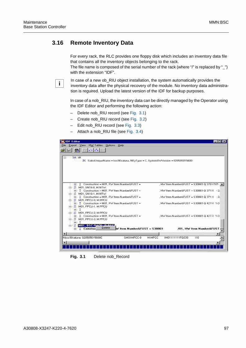
A30808-X3247-K220-4-7620 97
MaintenanceBase Station Controller
MMN:BSC
3.16 Remote Inventory Data
For every rack, the RLC provides one floppy disk which includes an inventory data filethat contains all the inventory objects belonging to the rack.The file name is composed of the serial number of the rack (where “/” is replaced by “_”)with the extension “IDF”.
In case of a nob_RIU, the inventory data can be directly managed by the Operator usingthe IDF Editor and performing the following action:
– Delete nob_RIU record (see Fig. 3.1)
– Create nob_RIU record (see Fig. 3.2)
– Edit nob_RIU record (see Fig. 3.3)
– Attach a nob_RIU file (see Fig. 3.4)
Fig. 3.1 Delete nob_Record
iIn case of a new ob_RIU object installation, the system automatically provides theinventory data after the physical recovery of the module. No inventory data administra-tion is reguired. Upload the latest version of the IDF for backup purposes.
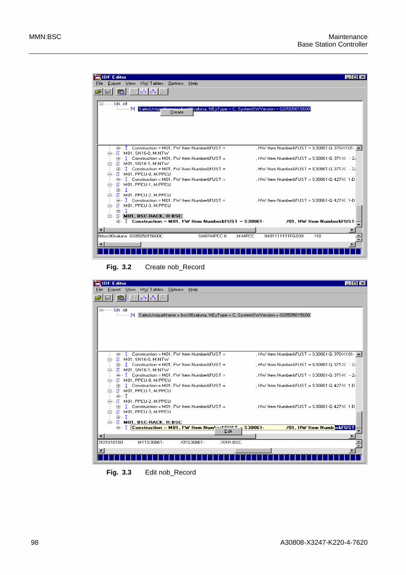
98 A30808-X3247-K220-4-7620
MMN:BSC MaintenanceBase Station Controller
Fig. 3.2 Create nob_Record
Fig. 3.3 Edit nob_Record
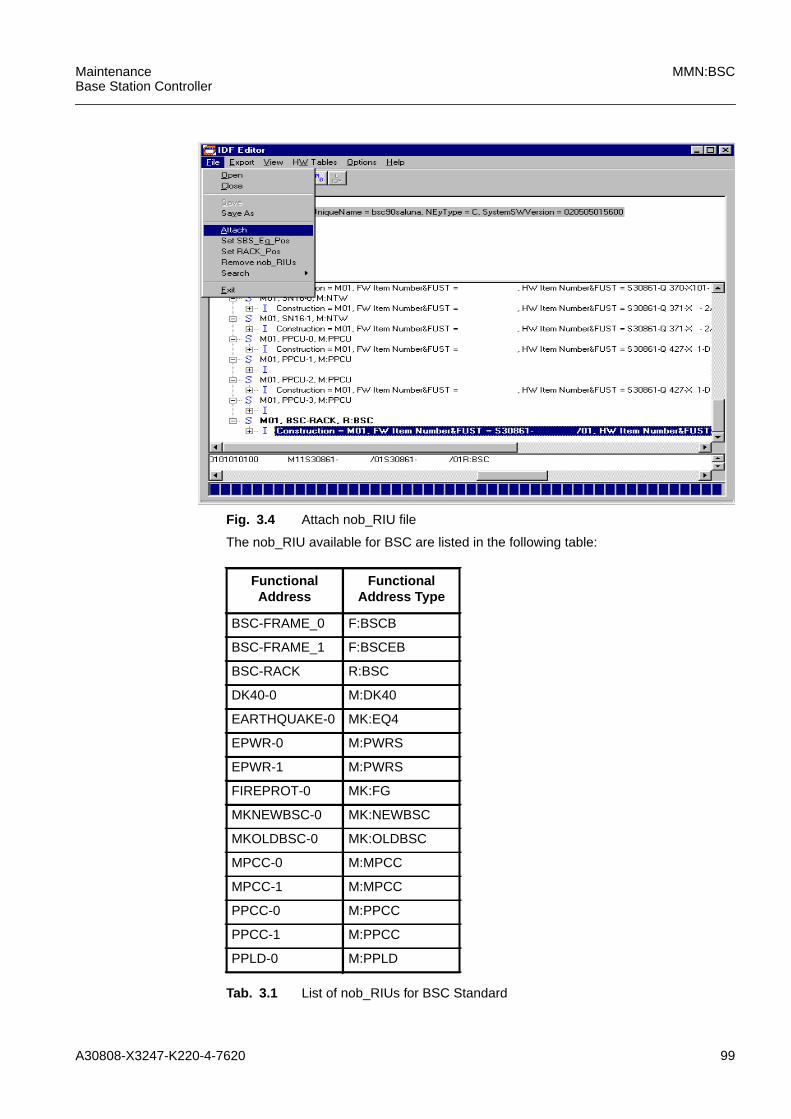
A30808-X3247-K220-4-7620 99
MaintenanceBase Station Controller
MMN:BSC
Fig. 3.4 Attach nob_RIU file
The nob_RIU available for BSC are listed in the following table:
FunctionalAddress
FunctionalAddress Type
BSC-FRAME_0 F:BSCB
BSC-FRAME_1 F:BSCEB
BSC-RACK R:BSC
DK40-0 M:DK40
EARTHQUAKE-0 MK:EQ4
EPWR-0 M:PWRS
EPWR-1 M:PWRS
FIREPROT-0 MK:FG
MKNEWBSC-0 MK:NEWBSC
MKOLDBSC-0 MK:OLDBSC
MPCC-0 M:MPCC
MPCC-1 M:MPCC
PPCC-0 M:PPCC
PPCC-1 M:PPCC
PPLD-0 M:PPLD
Tab. 3.1 List of nob_RIUs for BSC Standard

100 A30808-X3247-K220-4-7620
MMN:BSC MaintenanceBase Station Controller
PPLD-1 M:PPLD
PPLD-10 M:PPLD
PPLD-11 M:PPLD
PPLD-12 M:PPLD
PPLD-13 M:PPLD
PPLD-14 M:PPLD
PPLD-2 M:PPLD
PPLD-3 M:PPLD
PPLD-4 M:PPLD
PPLD-5 M:PPLD
PPLD-6 M:PPLD
PPLD-7 M:PPLD
PPLD-8 M:PPLD
PPLD-9 M:PPLD
PWRS-0 M:PWRS
PWRS-1 M:PWRS
FunctionalAddress
FunctionalAddress Type
Tab. 3.1 List of nob_RIUs for BSC Standard
FunctionalAddress
FunctionalAddress Type
BSC-FRAME_0 F:BSCB
BSC-FRAME_1 F:BSCEB
BSC-RACK R:BSC
EARTHQUAKE-0 MK:EQ4
FANB FANB
FIREPROT-0 MK:FG
MKNEWBSC-0 MK:NEWBSC
MKOLDBSC-0 MK:OLDBSC
MPCC-0 M:MPCC
MPCC-1 M:MPCC
PWRS-0 M:PWRS
PWRS-1 M:PWRS
Tab. 3.2 List of nob_RIUs for BSC High Capacity

A30808-X3247-K220-4-7620 101
MaintenanceBase Station Controller
MMN:BSC
1 Upload local IDT from the BSC
The user must enter the "Upload local idf file" command in order to create alocal copy of the file on the local LMT.
b Enter the following command:
2 Open IDT File
Start the IDF Editor from the LMT window and open the uploaded IDT file byselecting "File --> Open" menù.
To delete a nob_Record h...3To create a new nob_Record h...4To attach a nob_RIU file h...5To edit the RI-data from the replaced Unit h...6
3 Delete a nob_Record
Select the S-Record, open the "Delete" dialog box by clicking the right mousebutton to delete the S-Record.
☞ ......Fig. 3.1
If no additional modifications are necessary h...7
4 Create a new nob_Record
Select the N-Record, open the "Create" dialog box by clicking the right mousebutton and create a new nob_RIU object.
☞ ......Fig. 3.2
If no additional modifications are necessary h...7
LMT tree: MANAGED-ELEMENT--> BSS EQUIPMENT--> REMINV
Command: UPLLIDF REMINV
Name REMINV=<instance>
Attributes: DESTDIR = <..\idf\upload>
FILE = bsc.idt
OVERWRITE = <overwrite>
Submit
UPLLIDF REMINV:NAME=<instance>DESTDIR=<destdir>,FILE=”bsc01_1.idt”,OVERWRITE=YES;
102 A30808-X3247-K220-4-7620
MMN:BSC MaintenanceBase Station Controller
5 Attach nob_RIU file to actually loaded IDF or IDT
b To create a new nob_RIU file coming from the RLC disk, enter the followingcommand:
☞ ......Fig. 3.4
6 Edit the RI-data from the replaced Unit
Start the IDF-Editor and open the uploaded IDT file by selecting <File: Open>.
The following window appears, and all the RI-records are displayed. Thenob_RIU records are shown in bold letters.
Move the mouse cursor to the I-record to be updated and press the right mouse-button. The edit functionality is activated.
☞ ......Fig. 3.3
7 Remove all redundant nob_RIUs
After importing IDFs coming from the RLC or after replacing a card originally anob_RIU against another card, now having inventory data on board, the sameboard would be reported twice.
b Enter the following command:
This command can be applied only for IDFs with inventory of only one BSC. Itcannot be used for central IDF´s.
Command: <File: Attach>
Input: <NOB file to be attached>
Result: The inventory objects of the <NOB file to be attached> areattached to the actually loaded IDF or IDT. The number ofattached objects is displayed after command execution.
Command: <File: Remove nob_RIUs>
Input: <none>
A30808-X3247-K220-4-7620 103
MaintenanceBase Station Controller
MMN:BSC
8 Export nob_RIU file
b Enter the following command:
A copy of this NOB file is saved in the C:\LMT_root\..\idf\download directory,where it can be accessed only by the LMT during execution of the "Downloadnob_RIU" command.
The command is only applicable for IDFs with an inventory of one NE. It cannotbe applied to central IDFs. The filename is BSCNRIU for the BSC.
9 Download of the nob_RIU file
This step must be executed to transfer the file modified on the local LMT to theBSC.
b Enter the following command:
END
Command: <Export: NOB>
Input: <new filename>(default filename is retained from the "SalesUniqueName" field ofthe IDF)
Result: nob_RIU part of the modified IDF/IDT is saved for furtherprocessing
LMT tree: MANAGED-ELEMENT--> BSS EQUIPMENT--> BSCE --> REMINV
Command: DNLIDFD REMINV
Name: REMINV=<instance>
Attributes: SRCDIR = <..\idf\download>
Submit
DNLIDFD REMINV:NAME=REMINV:<instance>,SRCDIR=<..\idf\download>;

104 A30808-X3247-K220-4-7620
MMN:BSC MaintenanceBase Station Controller

A30808-X3247-K220-4-7620 105
MaintenanceBase Station Controller
MMN:BSC
3.17 SN16
This procedure requires execution of the NTW Procedure as a preliminary step.
Otherwise add a lock NTW command before replacing the module.
1 Lock the PWRS (Module Y) Corresponding to the Module to Replace
b Enter the following command:
System Response:LOCK ACK:NAME=PWRS:Y
2 Pull down the OFF REQ Switch on the PWRS Module Y
System Response:SYSTEMINFOREPORT:NAME=PWRS:YINFORMATION IDENTIFIER=POWER KEYLOCK SWITCH OFF
The red LED on module PWRS is switched on, if power is switched off.
3 Replace the Module
!If you add one or more cards without EPROM on board, the file containig the nob_RIUobjects must be modified, by means of the IDF Editor Tool, and then downloaded bythe LMT (see "3.16 Remote Inventory Data").
LMT tree: MANAGED-ELEMENT--> BSS-EQUIPMENT--> BSCE--> PWRD/EPWR
Command: LOCK PWRD orLOCK EPWR
Name: PWRD/EPWR:<Y>
Attributes: None
Submit
LOCK PWRD/EPWR:<Y>;
iThe modules connected to the PRWS-Y which has been switched off are put into the"disabled" state.
iIf the PWRS module Y is not in the locked state, it will not switch off.
!Follow the recommended instructions (see "1.5 Module ReplacementInstructions") and according to the rack structure (see "4 Hardware Equip-ment")

106 A30808-X3247-K220-4-7620
MMN:BSC MaintenanceBase Station Controller
4 Pull up the OFF REQ Switch on PWRS Module Y
System Response:SYSTEM INFOREPORT:NAME=PWRS:YINFORMATIONIDENTIFIER:POWER KEYLOCK SWITCH ON
5 Unlock the PWRS (Module Y) Corresponding to the Module to Replace
b Enter the following command:
System Response:UNLOCK ACK:NNAME=PWRS:Y
iThe modules connected to PWRS-Y (which has been switched on) remain in a"disabled dependency" state because PWRS-Y is LOCKED.
LMT tree: MANAGED-ELEMENT--> BSS-EQUIPMENT--> BSCE--> PWRD/EPWR
Command: UNLOCK PWRD orUNLOCK EPWR
Name: PWRD/EPWR:<instance>
Attributes: None
Submit
UNLOCK PWRD/EPWR:NAME=<instance>;
iAfter the PWRS-instance is “unlocked” the system puts into an “enabled” state allmodules connected to the PRWS-Y into an “enabled” state and executes the crosscopyof MPCC, TDPC and DISK and the loading of IXLT (Load from disk).
A30808-X3247-K220-4-7620 107
MaintenanceBase Station Controller
MMN:BSC
6 Start the Test on NTW Module
b Enter the following command:
It is possible to perform a test on the single module. The LMT tree is thefollowing:
If the start test pass. h...7
h...PROC: NTWProcedure
7 Unlock the NTW
b Enter the following command:
System Response:UNLOCK ACK NTW:NAME=NTW:<Instance>
LMT tree: MANAGED-ELEMENT--> BSS-EQUIPMENT--> BSCE
Command: PERFTEST BSCE
Name: BSCE:<instance>
Attributes: MORT = NTW:copy
Submit
Perftest BSCE:NAME=<instance>,MORT=<NTW:copy>;
LMT tree: MANAGED-ELEMENT--> BSS-EQUIPMENT--> BSCE --> NTW
Command: PERFTEST NTW
Name: NTW:<instance>
Submit
Perftest NTW:NAME=NTW<copy>;
iIf the test result is FAIL repeat the following step:- power off the PWRS module- reinsert the old replaced module- power on the PWRS module- go to step 3 of the NTW Procedure
LMT tree: MANAGED-ELEMENT--> BSS-EQUIPMENT--> BSCE--> NTW
Command: UNLOCK NTW
Name: NTW:<instance>
Attributes: None
Submit
UNLOCK NTW:NAME=NTW:<instance>;

108 A30808-X3247-K220-4-7620
MMN:BSC MaintenanceBase Station Controller
8 Update the RI file
Edit the RI-data by the IDF Editor Tool , update the Nob_Riu object file, exportand then download into BSC. h..."3.16 Remote
Inventory Data"
END. Return to the calling procedure.

A30808-X3247-K220-4-7620 109
MaintenanceBase Station Controller
MMN:BSC
3.18 SNAP
This procedure requires execution of the NTW Procedure as a preliminary step.
Otherwise enter the lock NTW command before replacing the module.
1 Lock the PWRS (Module Y) Corresponding to the Module to Replace
b Enter the following command:
System Response:LOCK ACK:NAME=PWRS:Y
2 Pull down the OFF REQ Switch on the PWRS Module Y
System Response:SYSTEMINFOREPORT:NAME=PWRS:YINFORMATION IDENTIFIER=POWER KEYLOCK SWITCH OFF
The red LED on module PWRS is switched on, if power is switched off.
3 Replace the Module
!If you add one or more cards without EPROM on board, the file containing thenob_RIU objects must be modified, by means of the IDF Editor Tool, and then down-loaded by the LMT (see "3.16 Remote Inventory Data").
LMT tree: MANAGED-ELEMENT--> BSS-EQUIPMENT--> BSCE--> PWRD/EPWR
Command: LOCK PWRD orLOCK EPWR
Name: PWRD/EPWR:<Y>
Attributes: None
Submit
LOCK PWRD/EPWR:<Y>;
iThe modules connected to the PRWS-Y which has been switched off are put into the"disabled" state.
iIf the PWRS module Y is not in the locked state, it will not switch off.
!Follow the recommended instructions (see "1.5 Module ReplacementInstructions") and according to the rack structure (see "4 Hardware Equip-ment")

110 A30808-X3247-K220-4-7620
MMN:BSC MaintenanceBase Station Controller
4 Disconnect the hot link and the hard disk connections between TDPCcopy 0 and copy 1
5 Pull up the OFF REQ Switch on PWRS Module Y
System Response:SYSTEM INFOREPORT:NAME=PWRS:YINFORMATIONIDENTIFIER:POWER KEYLOCK SWITCH ON
6 Unlock the PWRS (Module Y) Corresponding to the Module to Replace
b Enter the following command:
System Response:UNLOCK ACK:NNAME=PWRS:Y
7 Connect the hot link and the hard disk connections between TDPC copy 0and copy 1
iThe modules connected to PWRS-Y (which has been switched on) remain in a"disabled dependency" state because PWRS-Y is LOCKED.
LMT tree: MANAGED-ELEMENT--> BSS-EQUIPMENT--> BSCE--> PWRD/EPWR
Command: UNLOCK PWRD orUNLOCK EPWR
Name: PWRD/EPWR:<instance>
Attributes: None
Submit
UNLOCK PWRD/EPWR:NAME=<instance>;
iAfter the PWRS-instance is “unlocked” the system puts into an “enabled” state allmodules connected to the PRWS-Y into an “enabled” state and executes the crosscopyof MPCC, TDPC and DISK and the loading of IXLT (Load from disk).

A30808-X3247-K220-4-7620 111
MaintenanceBase Station Controller
MMN:BSC
8 Start the Test on NTW Module
b Enter the following command:
It is possible to perform a test on the single module. The LMT tree is thefollowing:
If the start test pass. h...9
h...PROC: NTWProcedure
LMT tree: MANAGED-ELEMENT--> BSS-EQUIPMENT--> BSCE
Command: PERFTEST BSCE
Name: BSCE:<instance>
Attributes: MORT = NTW:copy
Submit
Perftest BSCE:NAME=<instance>,MORT=<NTW:copy>;
LMT tree: MANAGED-ELEMENT--> BSS-EQUIPMENT--> BSCE --> NTW
Command: PERFTEST NTW
Name: NTW:<instance>
Submit
Perftest NTW:NAME=NTW<copy>;
iIf the test result is FAIL repeat the following step:- power off the PWRS module- reinsert the old replaced module- power on the PWRS module- go to step 3 of the NTW Procedure
112 A30808-X3247-K220-4-7620
MMN:BSC MaintenanceBase Station Controller
9 Unlock the NTW
b Enter the following command:
System Response:UNLOCK ACK NTW:NAME=NTW:<Instance>
END. Return to the calling procedure.
LMT tree: MANAGED-ELEMENT--> BSS-EQUIPMENT--> BSCE--> NTW
Command: UNLOCK NTW
Name: NTW:<instance>
Attributes: None
Submit
UNLOCK NTW:NAME=NTW:<instance>;
A30808-X3247-K220-4-7620 113
MaintenanceBase Station Controller
MMN:BSC
3.19 TDPC
1 Lock the Module before Substitution
b Enter the following command:
System Response:LOCK ACK TDPC:NAME=TDPC:<Instance>
2 Lock the PWRS (Module Y) Corresponding to the Module to Replace
b Enter the following command:
System Response:LOCK ACK:NAME=PWRS:Y
iAt least one MEMT copy must be enabled; therefore, activation might be necessaryprior to starting this procedure. For the second TDPC, the usual procedure can beapplied, see below.
!If you add one or more cards without EPROM on board, the file containing thenob_RIU objects must be modified, by means of the IDF Editor Tool, and then down-loaded by the LMT (see "3.16 Remote Inventory Data").
LMT tree: MANAGED-ELEMENT--> BSS-EQUIPMENT--> BSCE--> TDPC
Command: LOCK TDPC
Name: TDPC:<instance>
Submit
LOCK TDPC:NAME=TDPC:<instance>;
LMT tree: MANAGED-ELEMENT--> BSS-EQUIPMENT--> BSCE--> PWRD/EPWR
Command: LOCK PWRD orLOCK EPWR
Name: PWRD/EPWR:<Y>
Attributes: None
Submit
LOCK PWRD/EPWR:<Y>;
iThe modules connected to the PRWS-Y which has been switched off are put into the"disabled" state.
114 A30808-X3247-K220-4-7620
MMN:BSC MaintenanceBase Station Controller
3 Pull down the OFF REQ Switch on the PWRS Module Y
System Response:SYSTEMINFOREPORT:NAME=PWRS:YINFORMATION IDENTIFIER=POWER KEYLOCK SWITCH OFF
The red LED on module PWRS is switched on, if power is switched off.
4 Replace the module
Before extracting the module the hot link cable must be unplugged and tuckedout of the way.
5 Pull up the OFF REQ Switch on PWRS (Module Y) Corresponding to theModule to Replace
System Response:SYSTEM INFOREPORT:NAME=PWRS:YINFORMATIONIDENTIFIER:POWER KEYLOCK SWITCH ON
6 Unlock the PWRS module Y
b Enter the following command:
iIf the PWRS module Y is not in the locked state, it will not switch off.
!Follow the recommended instructions (see "1.5 Module ReplacementInstructions") and according to the rack structure (see "4 Hardware Equip-ment")
iThe modules connected to PWRS-Y (which has been switched on) remain in a"disabled dependency" state because PWRS-Y is LOCKED.
LMT tree: MANAGED-ELEMENT--> BSS-EQUIPMENT--> BSCE--> PWRD/EPWR
Command: UNLOCK PWRD orUNLOCK EPWR
Name: PWRD/EPWR:<instance>
Attributes: None
Submit
UNLOCK PWRD/EPWR:NAME=<instance>;
iAfter the PWRS-instance is “unlocked” the system puts into an “enabled” state allmodules connected to the PRWS-Y into an “enabled” state and executes the crosscopyof MPCC, TDPC and DISK and the loading of IXLT (Load from disk).

A30808-X3247-K220-4-7620 115
MaintenanceBase Station Controller
MMN:BSC
System Response:UNLOCK ACK:NNAME=PWRS:Y
7 Start the Test on TDPC Module
b Enter the following command:
It is possible to perform a test on the single module. The LMT tree is thefollowing:
If the start test pass. h...8
If the test result is FAIL and another module is in alarmed status and notreplaced yet, reinsert the old replaced module, because it’s possible the fault isin other part. h...END
LMT tree: MANAGED-ELEMENT--> BSS-EQUIPMENT--> BSCE
Command: PERFTEST BSCE
Name: BSCE:<instance>
Attributes: MORT = TDPC:copy
Submit
Perftest BSCE:NAME=<instance>,MORT=<TDPC:copy>;
LMT tree: MANAGED-ELEMENT--> BSS-EQUIPMENT--> BSCE --> TDPC
Command: PERFTEST TDPC
Name: TDPC:<instance>
Submit
Perftest TDPC:NAME=TDPC:<copy>;

116 A30808-X3247-K220-4-7620
MMN:BSC MaintenanceBase Station Controller
8 Unlock the Module after Substitution
b Enter the following command:
After the unlock command has been executed, the system starts the TDPCcrosscopy (it will take about 5 min). In the event of system fault after the cross-copy, repeat Step 5.
System Response:UNLOCK ACK TDPC:NAME=TDPC:<Instance>
END. Return to the calling procedure.
LMT tree: MANAGED-ELEMENT--> BSS-EQUIPMENT--> BSCE--> TDPC
Command: UNLOCK TDPC
Name: TDPC:<instance>
Attributes: None
Submit
UNLOCK TDPC:NAME=TDPC:<instance>;
A30808-X3247-K220-4-7620 117
MaintenanceBase Station Controller
MMN:BSC
3.20 UBEX
This procedure requires execution of the NTW Procedure as a preliminary step.
Otherwise, enter the lock NTW command before replacing the module.
1 Lock the PWRS (Module Y) Corresponding to the Module to Replace
b Enter the following command:
System Response:LOCK ACK:NAME=PWRS:Y
2 Pull down the OFF REQ Switch on the PWRS Module Y
System Response:SYSTEMINFOREPORT:NAME=PWRS:YINFORMATION IDENTIFIER=POWER KEYLOCK SWITCH OFF
The red LED on module PWRS is switched on, if power is switched off.
3 Replace the Module
!If you add one or more cards without EPROM on board, the file containing thenob_RIU objects must be modified, by means of the IDF Editor Tool, and then down-loaded by the LMT (see "3.16 Remote Inventory Data").
LMT tree: MANAGED-ELEMENT--> BSS-EQUIPMENT--> BSCE--> PWRD/EPWR
Command: LOCK PWRD orLOCK EPWR
Name: PWRD/EPWR:<Y>
Attributes: None
Submit
LOCK PWRD/EPWR:<Y>;
iThe modules connected to the PRWS-Y which has been switched off are put into the"disabled" state.
iIf the PWRS module Y is not in the locked state, it will not switch off.
!Follow the recommended instructions (see "1.5 Module ReplacementInstructions") and according to the rack structure (see "4 Hardware Equip-ment")

118 A30808-X3247-K220-4-7620
MMN:BSC MaintenanceBase Station Controller
4 Pull up the OFF REQ Switch on PWRS Module Y
System Response:SYSTEM INFOREPORT:NAME=PWRS:YINFORMATIONIDENTIFIER:POWER KEYLOCK SWITCH ON
5 Unlock the PWRS (Module Y) Corresponding to the Module to Replace
b Enter the following command:
System Response:UNLOCK ACK:NNAME=PWRS:Y
iThe modules connected to PWRS-Y (which has been switched on) remain in a"disabled dependency" state because PWRS-Y is LOCKED.
LMT tree: MANAGED-ELEMENT--> BSS-EQUIPMENT--> BSCE--> PWRD/EPWR
Command: UNLOCK PWRD orUNLOCK EPWR
Name: PWRD/EPWR:<instance>
Attributes: None
Submit
UNLOCK PWRD/EPWR:NAME=<instance>;
iAfter the PWRS-instance is “unlocked” the system puts into an “enabled” state allmodules connected to the PRWS-Y into an “enabled” state and executes the crosscopyof MPCC, TDPC and DISK and the loading of IXLT (Load from disk).

A30808-X3247-K220-4-7620 119
MaintenanceBase Station Controller
MMN:BSC
6 Start the Test on NTW Module
b Enter the following command:
It is possible to perform a test on the single module. The LMT tree is thefollowing:
If the start test pass. h...7
h...PROC: NTWProcedure
LMT tree: MANAGED-ELEMENT--> BSS-EQUIPMENT--> BSCE
Command: PERFTEST BSCE
Name: BSCE:<instance>
Attributes: MORT = NTW:copy
Submit
Perftest BSCE:NAME=<instance>,MORT=<NTW:copy>;
LMT tree: MANAGED-ELEMENT--> BSS-EQUIPMENT--> BSCE --> NTW
Command: PERFTEST NTW
Name: NTW:<instance>
Submit
Perftest NTW:NAME=NTW<copy>;
iIf the test result is FAIL repeat the following step:- power off the PWRS module- reinsert the old replaced module- power on the PWRS module- go to step 3 of the NTW Procedure

120 A30808-X3247-K220-4-7620
MMN:BSC MaintenanceBase Station Controller
7 Unlock the NTW
b Enter the following command:
System Response:UNLOCK ACK NTW:NAME=NTW:<Instance>
END. Return to the calling procedure.
LMT tree: MANAGED-ELEMENT--> BSS-EQUIPMENT--> BSCE--> NTW
Command: UNLOCK NTW
Name: NTW:<instance>
Attributes: None
Submit
UNLOCK NTW:NAME=NTW:<instance>;

A30808-X3247-K220-4-7620 121
MaintenanceBase Station Controller
MMN:BSC
4 Hardware Equipment
BSC rack layout
The BSC is available in the following configuration:
base subrack (BSCB) and expansion subrack (BSCE).
Fig. 4.1 identifies the regular capacity BSC rack image, both for the base and the exten-sion subracks.
Fig. 4.2 identifies the regular capacity BSC rack image for the GPRS feature.
Fig. 4.3 identifies the high capacity BSC rack image, both for the base and the exten-sion subracks.
Fig. 4.4 identifies the high capacity BSC rack image in fire resistence version, both forthe base and extension subracks.
Fig. 4.5 identifies the high capacity BSC - 120 channels rack image, both for the baseand the extension subracks.
The expansion subrack is shown in the maximum configuration.
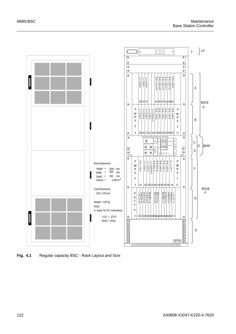
122 A30808-X3247-K220-4-7620
MMN:BSC MaintenanceBase Station Controller
Fig. 4.1 Regular capacity BSC - Rack Layout and Size
18 23 27 42 46 50 54 58 62
PPLD14
PPLD13
PPLD12
PPLD11
PPLD10
PPLD9
18 23 27 42 46 50 54 58 62
PPLD7
PPLD6
PPLD5
PPLD4
PPLD3
P
WRS
0
P
WRS
1
3 31 35 71
18
PPLH
25 29 43 48 53 58 63 71
0
12
IXLT
17 25 3944 54586368
0
UBEX0
P
WRS
0
2 3034 71
D
K40
0
P
WRS
1
PPCC
38333
10
PPCC0
PPLD2
PPLD1
PPLD0
PLLH1
SNXX0
TDPC0
MEMT0
MPCC0
MPCC1
MEMT1
TDPC1
SNXX1
UBEX1
IXLT1
20 49
2000600
Rack dimensions:
Width
Volume
=
300mmmm
mm
Card dimensions:
220 x 278 mm
Weight = 128 Kg
Notes:s= spare, for N+1 redundancy
SNXX = SN16
Height
Depth
=
==
0,260 m3
= QTLP
T
A
B
C
E
D
G
LP
BSCE
BFAP
BSCB
O
F
A
F
OPDS
LICD8
LICD7
LICD6
LICD5
LICD4
LICD3
LICD2
LICD
PPLD8
LICD1
LICD0
LICDS
S1
LICD
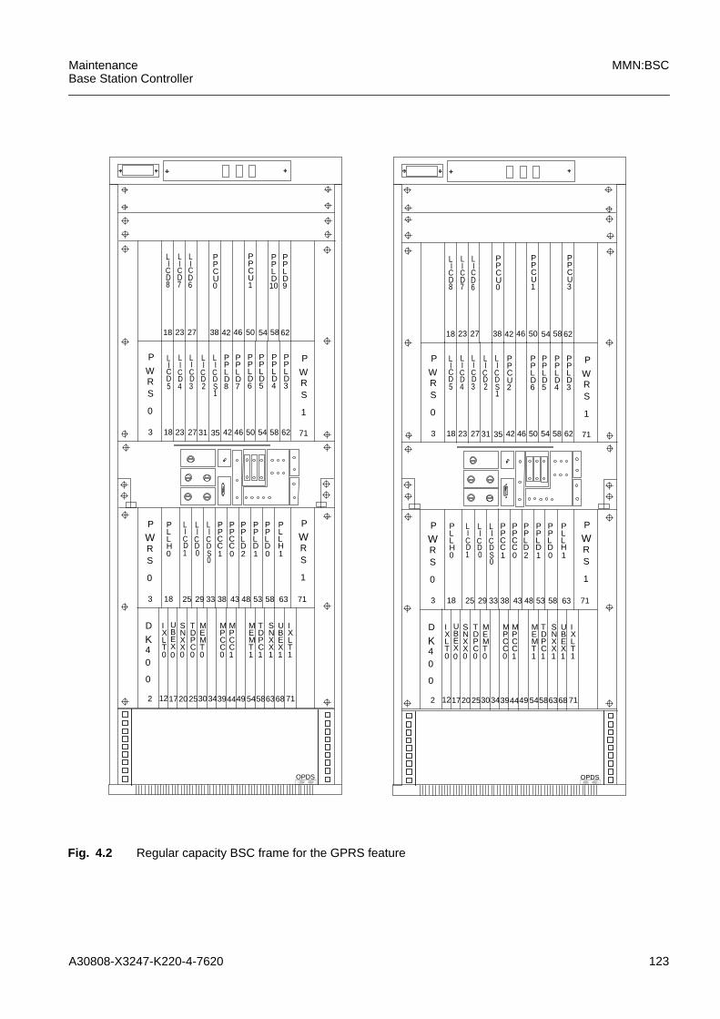
A30808-X3247-K220-4-7620 123
MaintenanceBase Station Controller
MMN:BSC
Fig. 4.2 Regular capacity BSC frame for the GPRS feature
18 23 27 42 46 50 54 58 62
PPCU1
18 23 27 42 46 50 54 58 62
PPLD6
PPLD5
PPLD4
PPLD3
P
WRS
0
P
WRS
1
3 31 35 71
18
PLLH
25 29 43 48 53 58 63 71
0
12
IXLT
17 25 3944 54586368
0
UBEX0
P
WRS
0
2 3034 71
D
K40
0
P
WRS
1
PPCC
38333
1
PPCC0
PPLD2
PPLD1
PPLD0
PLLH1
SNXX0
TDPC0
MEMT0
MPCC0
MPCC1
MEMT1
TDPC1
SNXX1
UBEX1
IXLT1
20 49
38
PPCU0
18 23 27 42 46 50 54 58 62
PPCU1
PPCU3
18 23 27 42 46 50 54 58 62
PPCU2
PPLD6
PPLD5
PPLD4
PPLD3
P
WRS
0
P
WRS
1
3 31 35 71
18
PLLH
25 29 43 48 53 58 63 71
0
12
IXLT
17 25 3944 54586368
0
UBEX0
P
WRS
0
2 3034 71
D
K40
0
P
WRS
1
PPCC
38333
1
PPCC0
PPLD2
PPLD1
PPLD0
PLLH1
SNXX0
TDPC0
MEMT0
MPCC0
MPCC1
MEMT1
TDPC1
SNXX1
UBEX1
IXLT1
20 49
38
PPCU0
PPLD8
PPLD7
PPLD10
PPLD9
OPDSOPDS
LI
CD8
LICD7
LICD6
LICD5
LICD4
LICD3
LI
CD2
LI
CDS1
LICD1
LI
CD0
LI
CDS0
LICD1
LI
CD0
LI
CDS0
LICD5
LICD4
LICD3
LI
CD2
LI
CDS1
LI
CD8
LICD7
LICD6

124 A30808-X3247-K220-4-7620
MMN:BSC MaintenanceBase Station Controller
Fig. 4.3 High Capacity BSC frame
18
QTLP
23 27 42 46 50 54 58 62
8
QTLP7
QTLP6
18
QTLP
23 27 42 46 50 54 58 62
5
QTLP4
QTLP3
QTLP2
QTLPS1
P
WRS
0
P
WRS
1
3 31 35 71
18
PLLH
25 29 43 48 53 58 63 71
0
12
IXLT
17 25 3944 54586368
0
UBEX0
P
WRS
0
2 3034 71
D
K40
0
P
WRS
1
PPXL
QTLPS
38333
10
QTLP0
QTLP1
PPXL0
PLLH1
SNAP0
TDPC0
MEMT0
MPCC0
MPCC1
MEMT1
TDPC1
SNAP1
UBEX1
IXLT1
20 49
38
PPXU0
PPXU1
PPXU2
PPXU3
PPXU5
PPXU4
T
A
B
C
E
G
LP
BSCE
BFAP
BSCB
O
F
A
F
D
H
OPDS

A30808-X3247-K220-4-7620 125
MaintenanceBase Station Controller
MMN:BSC
Fig. 4.4 High Capacity BSC in fire resistence cabinet version
18
QTLP
23 27 42 46 50 54 58 62
8
QTLP7
QTLP6
18
QTLP
23 27 42 46 50 54 58 62
5
QTLP4
QTLP3
QTLP2
QTLPS1
P
WRS
0
P
WRS
1
3 31 35 71
18
PLLH
25 29 43 48 53 58 63 71
0
12
IXLT
17 25 3944 54586368
0
UBEX0
P
WRS
0
2 3034 71
D
K40
0
P
WRS
1
PPXL
QTLPS
38333
10
QTLP0
QTLP1
PPXL0
PLLH1
SNAP0
TDPC0
MEMT0
MPCC0
MPCC1
MEMT1
TDPC1
SNAP1
UBEX1
IXLT1
20 49
38
PPXU0
PPXU1
PPXU2
PPXU3
PPXU5
PPXU4
T
A
B
C
E
G
LP
BSCE
BFAP
BSCB
O
F
A
F
D
H
OPDS
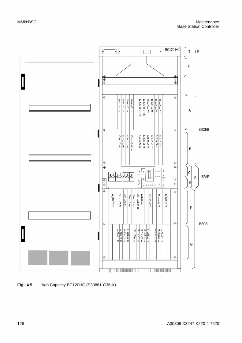
126 A30808-X3247-K220-4-7620
MMN:BSC MaintenanceBase Station Controller
Fig. 4.5 High Capacity BC120HC (S30861-C36-X)
TLP7
STLP5
STLP4
STLP3
STLPS1
PLLH0
IXLT0
UBEX0
PWRS0
PWRS1
PPXL
STLPS 10
STLP0
STLP1
PPXL0
PLLH1
SNAP0
TDPC0
MEMT0
MPCC0
MPCC1
MEMT1
TDPC1
SNAP1
UBEX1
IXLT1
PPXU1
PPXU3
PPXU5
PPXU6
PPXU1
PPXU8
T
A
B
C
E
G
LP
BSCEB
BFAP
BSCB
F
D
STLP8
STLP9
STLP6
S PPXU1
PPXU9
PPXU7
01
PPXU2
PPXU4
PPXU0
STLP2
H
BC120 HC

A30808-X3247-K220-4-7620 127
MaintenanceBase Station Controller
MMN:BSC
!PWRS V4 is considered mandatory inside the BSC Expansion Rack in case of upgradeto High Capacity or in case of a new BSC HC field installation.
!It is implicitly assumed the usage of QTLP V2; this type of LICD indeed allows themaximum flexibility in the availability of PCM ports.

128 A30808-X3247-K220-4-7620
MMN:BSC MaintenanceBase Station Controller

A30808-X3247-K220-4-7620 129
MaintenanceBase Station Controller
MMN:BSC
4.1 Rack Connections
Fig. 4.6 identifies the rack connection blocks.
Fig. 4.6 BSC Rack Connection Blocks
Tab. 4.1 identifies the correspondence between the connector pins for the PCM line(120 Ohm) and the PCM line wires, identified by the number of the line within a QTLPboard, receiving or transmitting side, wire A or B.
Y0
Y1
Y3
Y2
W40W26
to GND-48 + -48 +
to GND
W2W3
PP0 PP1
Y4
Y5
Y6
Y7
RAS
PM2
RGB
PM3W20
W10
Temp. Sensors
GND bold
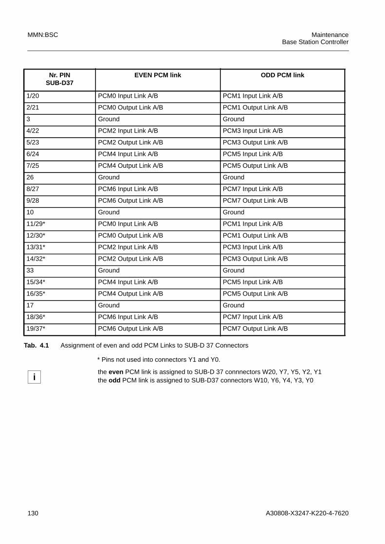
130 A30808-X3247-K220-4-7620
MMN:BSC MaintenanceBase Station Controller
* Pins not used into connectors Y1 and Y0.
Nr. PINSUB-D37
EVEN PCM link ODD PCM link
1/20 PCM0 Input Link A/B PCM1 Input Link A/B
2/21 PCM0 Output Link A/B PCM1 Output Link A/B
3 Ground Ground
4/22 PCM2 Input Link A/B PCM3 Input Link A/B
5/23 PCM2 Output Link A/B PCM3 Output Link A/B
6/24 PCM4 Input Link A/B PCM5 Input Link A/B
7/25 PCM4 Output Link A/B PCM5 Output Link A/B
26 Ground Ground
8/27 PCM6 Input Link A/B PCM7 Input Link A/B
9/28 PCM6 Output Link A/B PCM7 Output Link A/B
10 Ground Ground
11/29* PCM0 Input Link A/B PCM1 Input Link A/B
12/30* PCM0 Output Link A/B PCM1 Output Link A/B
13/31* PCM2 Input Link A/B PCM3 Input Link A/B
14/32* PCM2 Output Link A/B PCM3 Output Link A/B
33 Ground Ground
15/34* PCM4 Input Link A/B PCM5 Input Link A/B
16/35* PCM4 Output Link A/B PCM5 Output Link A/B
17 Ground Ground
18/36* PCM6 Input Link A/B PCM7 Input Link A/B
19/37* PCM6 Output Link A/B PCM7 Output Link A/B
Tab. 4.1 Assignment of even and odd PCM Links to SUB-D 37 Connectors
ithe even PCM link is assigned to SUB-D 37 connnectors W20, Y7, Y5, Y2, Y1the odd PCM link is assigned to SUB-D37 connectors W10, Y6, Y4, Y3, Y0
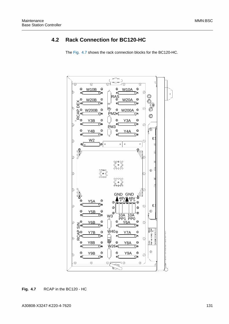
A30808-X3247-K220-4-7620 131
MaintenanceBase Station Controller
MMN:BSC
4.2 Rack Connection for BC120-HC
The Fig. 4.7 shows the rack connection blocks for the BC120-HC.
Fig. 4.7 RCAP in the BC120 - HC
+ +
W10B
W200B
W20B
Y3B
Y4B
W200A
Y4A
Y3A
Y5A
Y5B
Y6B
Y7B
Y9B Y9A
48VGNDGND
RC
AP
DE
XR
CA
P S
IN
W3
W26
W40
RAS
PM2
PM3
W2
Y7A
Y8AY8B
W10A
W20A
PP0Y6A
PP110A10A
48V
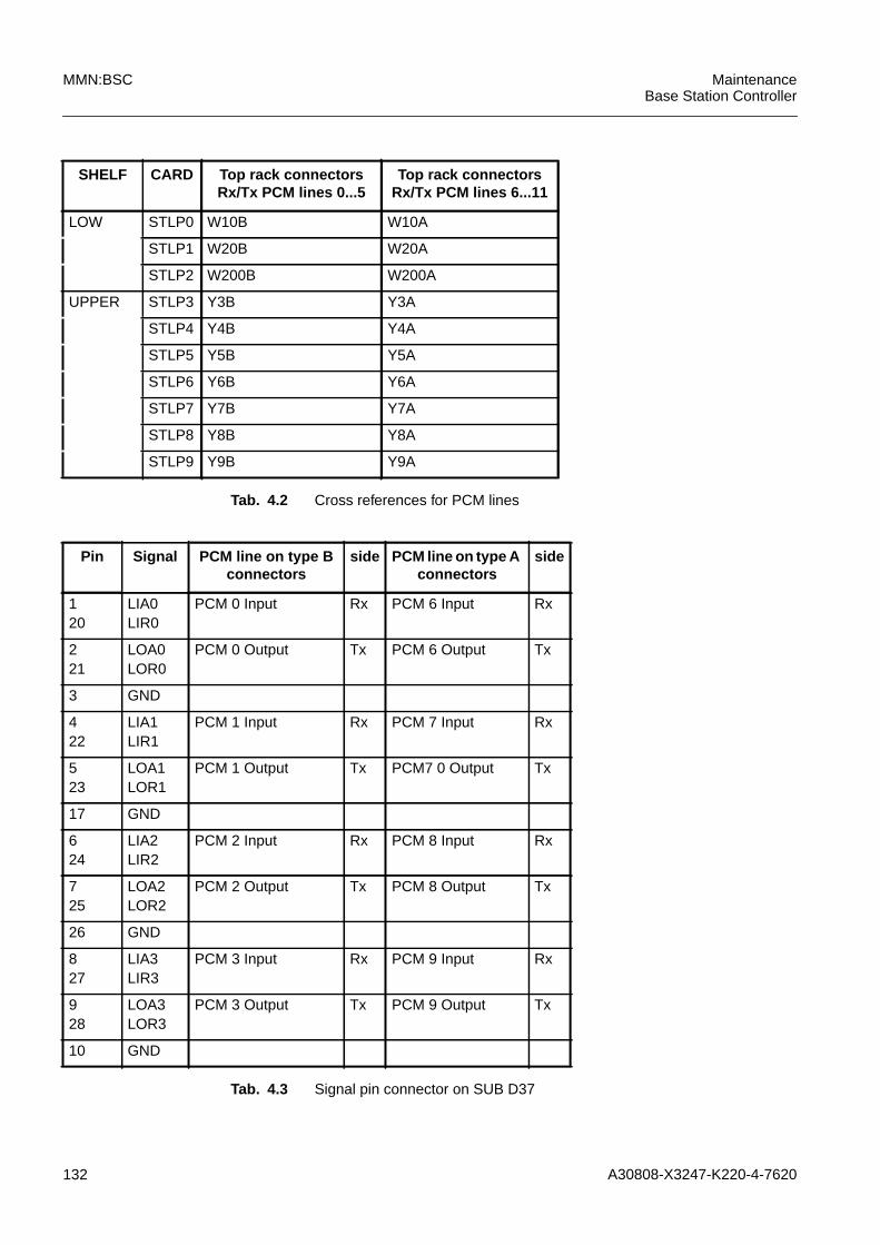
132 A30808-X3247-K220-4-7620
MMN:BSC MaintenanceBase Station Controller
SHELF CARD Top rack connectorsRx/Tx PCM lines 0...5
Top rack connectorsRx/Tx PCM lines 6...11
LOW STLP0 W10B W10A
STLP1 W20B W20A
STLP2 W200B W200A
UPPER STLP3 Y3B Y3A
STLP4 Y4B Y4A
STLP5 Y5B Y5A
STLP6 Y6B Y6A
STLP7 Y7B Y7A
STLP8 Y8B Y8A
STLP9 Y9B Y9A
Tab. 4.2 Cross references for PCM lines
Pin Signal PCM line on type Bconnectors
side PCM line on type Aconnectors
side
120
LIA0LIR0
PCM 0 Input Rx PCM 6 Input Rx
221
LOA0LOR0
PCM 0 Output Tx PCM 6 Output Tx
3 GND
422
LIA1LIR1
PCM 1 Input Rx PCM 7 Input Rx
523
LOA1LOR1
PCM 1 Output Tx PCM7 0 Output Tx
17 GND
624
LIA2LIR2
PCM 2 Input Rx PCM 8 Input Rx
725
LOA2LOR2
PCM 2 Output Tx PCM 8 Output Tx
26 GND
827
LIA3LIR3
PCM 3 Input Rx PCM 9 Input Rx
928
LOA3LOR3
PCM 3 Output Tx PCM 9 Output Tx
10 GND
Tab. 4.3 Signal pin connector on SUB D37
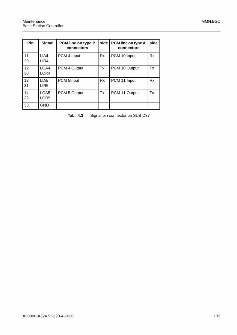
A30808-X3247-K220-4-7620 133
MaintenanceBase Station Controller
MMN:BSC
1129
LIA4LIR4
PCM 4 Input Rx PCM 10 Input Rx
1230
LOA4LOR4
PCM 4 Output Tx PCM 10 Output Tx
1331
LIA5LIR5
PCM 5Input Rx PCM 11 Input Rx
1432
LOA5LOR5
PCM 5 Output Tx PCM 11 Output Tx
33 GND
Pin Signal PCM line on type Bconnectors
side PCM line on type Aconnectors
side
Tab. 4.3 Signal pin connector on SUB D37
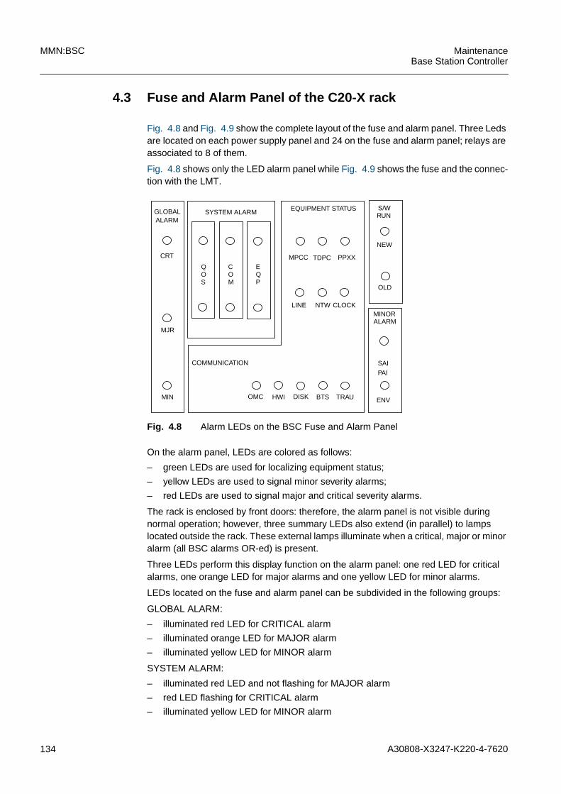
134 A30808-X3247-K220-4-7620
MMN:BSC MaintenanceBase Station Controller
4.3 Fuse and Alarm Panel of the C20-X rack
Fig. 4.8 and Fig. 4.9 show the complete layout of the fuse and alarm panel. Three Ledsare located on each power supply panel and 24 on the fuse and alarm panel; relays areassociated to 8 of them.
Fig. 4.8 shows only the LED alarm panel while Fig. 4.9 shows the fuse and the connec-tion with the LMT.
Fig. 4.8 Alarm LEDs on the BSC Fuse and Alarm Panel
On the alarm panel, LEDs are colored as follows:
– green LEDs are used for localizing equipment status;
– yellow LEDs are used to signal minor severity alarms;
– red LEDs are used to signal major and critical severity alarms.
The rack is enclosed by front doors: therefore, the alarm panel is not visible duringnormal operation; however, three summary LEDs also extend (in parallel) to lampslocated outside the rack. These external lamps illuminate when a critical, major or minoralarm (all BSC alarms OR-ed) is present.
Three LEDs perform this display function on the alarm panel: one red LED for criticalalarms, one orange LED for major alarms and one yellow LED for minor alarms.
LEDs located on the fuse and alarm panel can be subdivided in the following groups:
GLOBAL ALARM:
– illuminated red LED for CRITICAL alarm
– illuminated orange LED for MAJOR alarm
– illuminated yellow LED for MINOR alarm
SYSTEM ALARM:
– illuminated red LED and not flashing for MAJOR alarm
– red LED flashing for CRITICAL alarm
– illuminated yellow LED for MINOR alarm
ENV
SAIPAI
MINORALARM
S/WRUN
NEW
OLD
EQUIPMENT STATUS
MPCC TDPC PPXX
LINE NTW CLOCK
TRAUBTSDISKHWIOMC
COMMUNICATION
GLOBALALARM
MIN
EQP
COM
QOS
SYSTEM ALARM
CRT
MJR
A30808-X3247-K220-4-7620 135
MaintenanceBase Station Controller
MMN:BSC
EQUIPMENT STATUS - COMMUNICATION:
– green illuminated LED for no alarm
– green LED flashing for alarm
Tab. 4.4 describes the correspondence between the LEDs on the fuse and alarm paneland the related objects in the Equipment and Communication areas. The first columnreports the LEDs; the second column contains the list of the physical objects that willswitch on in the event of fault.
S/W RUN (NEW and OLD):
– S/W RUN LEDs are normally switched off. They illuminate only during the changeversion procedure.
– When a LED is illuminated, it indicates which software version is currently running.
– These LEDs switch off when the operator enters the appropriate command (end ofchange version).
MINOR ALARM:
SAI PAI
– alarm related to PCMS lines
– alarm related to PCMB lines
ENV
– illuminated and not flashing indicates a MINOR alarm;
– slow flashing indicates a MAJOR alarm;
– fast flashing indicates a CRITICAL alarm.
ENV LED switches on when there's an enviromental alarm such as smoke, intrusion, fireor temperature.
LED - LocalizationQueue
Corresponding modules/objects
MPCC MPCC, PWRD
TDPC TDPC, MEMT
PPXX PPLD, PPCC, PPCU, PPXL, PPXU
LINE PCMA, SS7L, TSLA
NTW SN16, UBEX, PLLH, SNAP
CLOCK SYNC, SYNE
OMC OMAL, X25A, X25D, CBCL
HWI IXLT, LICD, LICDS, EPWR
DISK DK40, DISK
BTS BTSM, BTS, TRX, CHAN
TRAU TRAU
Tab. 4.4 LED-Hardware Correspondence
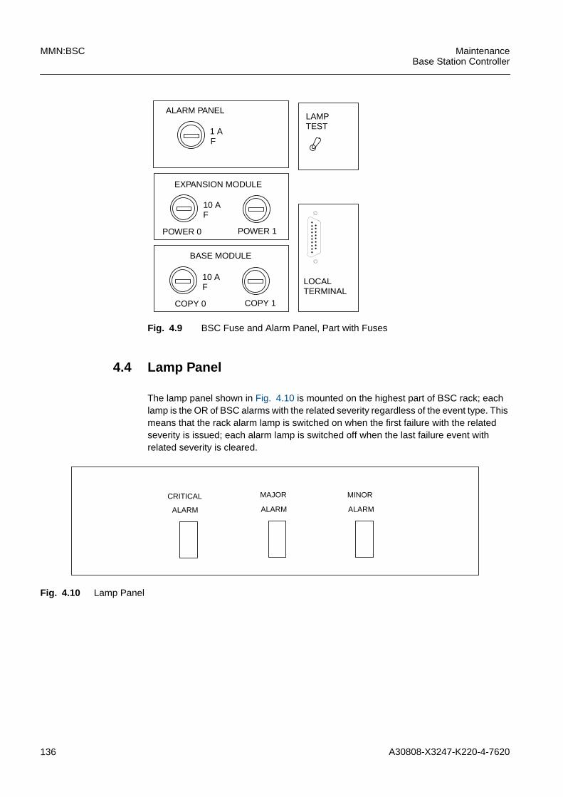
136 A30808-X3247-K220-4-7620
MMN:BSC MaintenanceBase Station Controller
Fig. 4.9 BSC Fuse and Alarm Panel, Part with Fuses
4.4 Lamp Panel
The lamp panel shown in Fig. 4.10 is mounted on the highest part of BSC rack; eachlamp is the OR of BSC alarms with the related severity regardless of the event type. Thismeans that the rack alarm lamp is switched on when the first failure with the relatedseverity is issued; each alarm lamp is switched off when the last failure event withrelated severity is cleared.
Fig. 4.10 Lamp Panel
ALARM PANEL
1 AF
EXPANSION MODULE
POWER 0 POWER 1
10 AF
LAMPTEST
BASE MODULE
COPY 0 COPY 1
10 AF
LOCALTERMINAL
CRITICAL
ALARM
MAJOR
ALARM
MINOR
ALARM
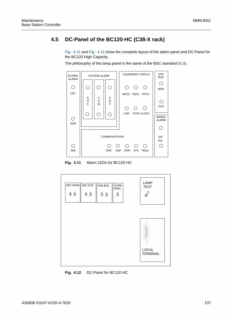
A30808-X3247-K220-4-7620 137
MaintenanceBase Station Controller
MMN:BSC
4.5 DC-Panel of the BC120-HC (C38-X rack)
Fig. 4.11 and Fig. 4.12 show the complete layout of the alarm panel and DC-Panel forthe BC120 High Capacity.
The philosophy of the lamp panel is the same of the BSC standard (4.3).
Fig. 4.11 Alarm LEDs for BC120 HC
Fig. 4.12 DC-Panel for BC120 HC
SAIPAI
MINORALARM
S/WRUN
NEW
OLD
EQUIPMENT STATUS
MPCC TDPC PPXX
LINE NTW CLOCK
TRAUSTSDISKHWIOMC
COMMUNICATION
GLOBALALARM
MIN
EQP
COM
QOS
SYSTEM ALARM
CRT
MJR
LAMPTEST
LOCALTERMINAL
BSC BASE BSC EXP FAN BOX ALARMPANEL
138 A30808-X3247-K220-4-7620
MMN:BSC MaintenanceBase Station Controller
4.6 Temperature Sensors
Two Temperature sensors are mounted on the top of the rack (see Fig. 4.6): each oneof them controls a copy of the Power Suppliers.
When the temperature increases, the temperature sensor contact closes and the rele-vant supplier goes out of service (OFF).
If during normal operating status, the equipment internal temperature reaches the 72˚Cthreshold, Copy 0 temperature sensor contacts close and the suppliers of the relevantcopy go out of service (OFF).
Copy 0 will restore (opening of TS contacts and suppliers returning in service (ON))when the temperature returns to 63˚C threshold.
If the temperature keeps increasing and reaches a 78˚C threshold, Copy 1 temperaturesensor contacts close and the suppliers of the relevant copy go out of service (OFF).
At this point there is no power supply in the whole equipment and Copy 0 and Copy 1will restore (operning of TS contacts and soppliers returning in service (ON)) when thetemperature returns to 63˚C threshold.
Each Temperature Sensor is tested singularly by means of a heating board adjusted to:
A tester can be used to verify whether the contact is open or closed.
Copy 0 TS 72˚C close Suppliers OFF
Copy 1 TS 78˚C close Suppliers OFF
72˚C for Copy 0 power suppliers78˚C for Copy 1 power suppliers63˚C the contact reopens
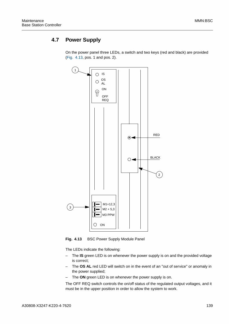
A30808-X3247-K220-4-7620 139
MaintenanceBase Station Controller
MMN:BSC
4.7 Power Supply
On the power panel three LEDs, a switch and two keys (red and black) are provided(Fig. 4.13, pos. 1 and pos. 2).
Fig. 4.13 BSC Power Supply Module Panel
The LEDs indicate the following:
– The IS green LED is on whenever the power supply is on and the provided voltageis correct;
– The OS AL red LED will switch on in the event of an "out of service" or anomaly inthe power supplied;
– The ON green LED is on whenever the power supply is on.
The OFF REQ switch controls the on/off status of the regulated output voltages, and itmust be in the upper position in order to allow the system to work.
IS
OSAL
ON
OFFREQ
1
M1+12,3
M2 + 5,3
M3 PPW
ON
RED
BLACK
2
3
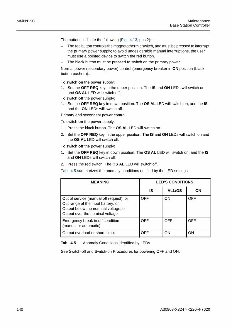
140 A30808-X3247-K220-4-7620
MMN:BSC MaintenanceBase Station Controller
The buttons indicate the following (Fig. 4.13, pos 2):
– The red button controls the magnetothermic switch, and must be pressed to interruptthe primary power supply; to avoid undesiderable manual interruptions, the usermust use a pointed device to switch the red button.
– The black button must be pressed to switch on the primary power.
Normal power (secondary power) control (emergency breaker in ON position (blackbutton pushed)):.
Primary and secondary power control:
To switch on the power supply:
1. Press the black button. The OS AL LED will switch on.
2. Set the OFF REQ key in the upper position. The IS and ON LEDs will switch on andthe OS AL LED will switch off.
To switch off the power supply:
1. Set the OFF REQ key in down position. The OS AL LED will switch on, and the ISand ON LEDs will switch off:
2. Press the red switch. The OS AL LED will switch off.
Tab. 4.5 summarizes the anomaly conditions notified by the LED settings.
See Switch-off and Switch-on Procedures for powering OFF and ON.
To switch on the power supply:1. Set the OFF REQ key in the upper position. The IS and ON LEDs will switch on
and OS AL LED will switch off.To switch off the power supply:1. Set the OFF REQ key in down position. The OS AL LED will switch on, and the IS
and the ON LEDs will switch off.
MEANING LED’S CONDITIONS
IS ALL/OS ON
Out of service (manual off request), orOut range of the input battery, orOutput below the nominal voltage, orOutput over the nominal voltage
OFF ON OFF
Emergency break in off condition(manual or automatic)
OFF OFF OFF
Output overload or short circuit OFF ON ON
Tab. 4.5 Anomaly Conditions identified by LEDs

A30808-X3247-K220-4-7620 141
MaintenanceBase Station Controller
MMN:BSC
4.8 Jumpers setting
4.8.1 Module DK40
Fig. 4.14 Jumpers Setting for Module DK40
321SEZ5
3
21
SEZ0
SEZ0
SEZ0
SEZ0
SEZ07
SEZ09
2 3 1 4
SEZ08
SEZ11
SEZ06
SEZ10
iThe configuration of jumpers SEZ01..SEZ04 is relevant to the RS232 interface. For theV11 interface, these jumpers must be set in the position 2-3.
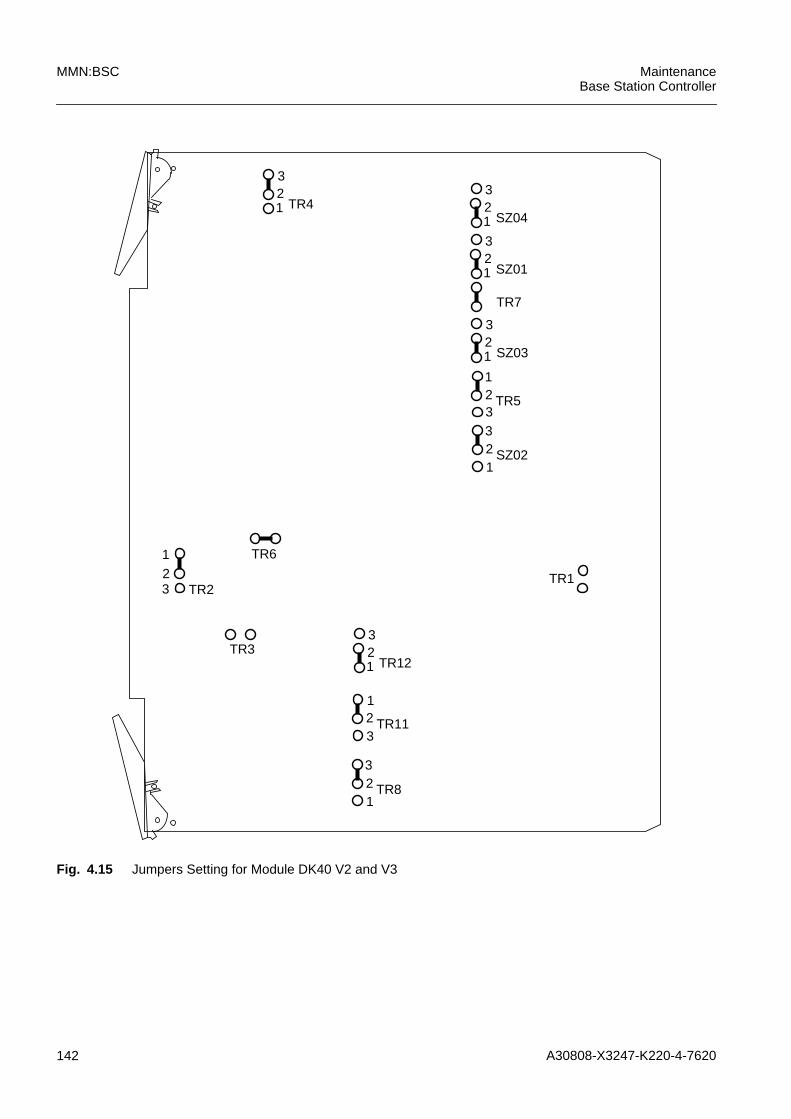
142 A30808-X3247-K220-4-7620
MMN:BSC MaintenanceBase Station Controller
Fig. 4.15 Jumpers Setting for Module DK40 V2 and V3
SZ04
TR1
TR6
123
TR4123
SZ01123
TR7
SZ03123
TR5
3
21
SZ0212
3
TR2321
TR3TR121
23
TR1132
TR812
1
3

A30808-X3247-K220-4-7620 143
MaintenanceBase Station Controller
MMN:BSC
4.8.2 Module IXLT
Fig. 4.16 Jumpers Setting for Module IXLT V3 and V4
TR22
TR20
TR3123
TR8TR18
TR2812
3
TR19
TR26
3 2 1
TR24
1 2 3TR25
1 2 3 TR1
TR21
TR4
TR5
TR7
TR6
TR27
1 2 3
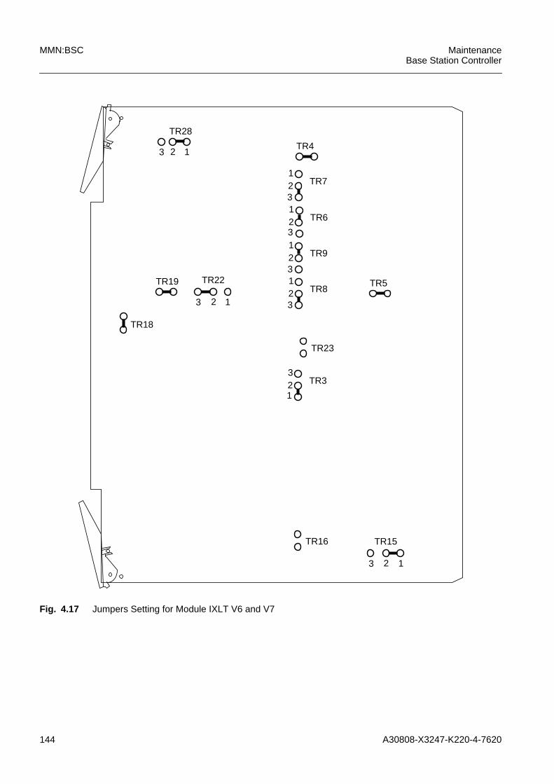
144 A30808-X3247-K220-4-7620
MMN:BSC MaintenanceBase Station Controller
Fig. 4.17 Jumpers Setting for Module IXLT V6 and V7
TR18
TR19
TR28
3 2 1TR4
TR22
3 2 1
TR7123
TR6123
TR9123
TR8123
TR23
TR16 TR15
3 2 1
TR5
TR3321
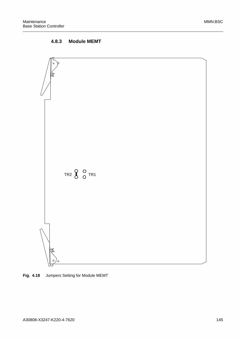
A30808-X3247-K220-4-7620 145
MaintenanceBase Station Controller
MMN:BSC
4.8.3 Module MEMT
Fig. 4.18 Jumpers Setting for Module MEMT
TR1TR2

146 A30808-X3247-K220-4-7620
MMN:BSC MaintenanceBase Station Controller
4.8.4 Module MPCC
Fig. 4.19 Jumpers Setting for Module MPCC V7
TR16
TRWDT
3
21
TRBF2
TR1
TRMMXTR_FW
TR_BIST
TR_FLASH
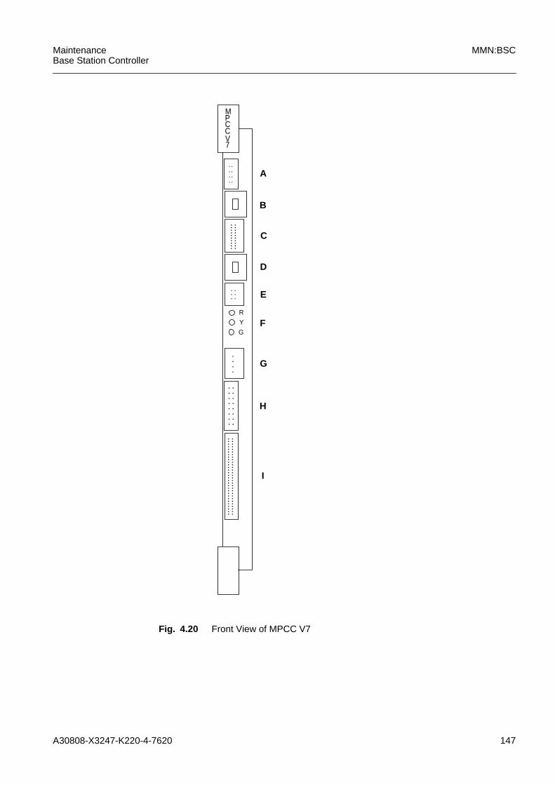
A30808-X3247-K220-4-7620 147
MaintenanceBase Station Controller
MMN:BSC
Fig. 4.20 Front View of MPCC V7
: : : :
: : :
: : :
: :
MPCCV7
A
B
C
D
E
F
G
: : :
::::::
::::::
::::::
::::::
::::::
R
Y
G
H
I
::::::
::::
. . . .
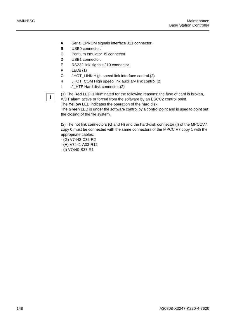
148 A30808-X3247-K220-4-7620
MMN:BSC MaintenanceBase Station Controller
A Serial EPROM signals interface J11 connector.B USB0 connector.C Pentium emulator J5 connector.D USB1 connector.E RS232 link signals J10 connector.F LEDs (1)G JHOT_LINK High speed link interface control.(2)H JHOT_COM High speed link auxiliary link control.(2)I J_HTF Hard disk connector.(2)
i(1) The Red LED is illuminated for the following reasons: the fuse of card is broken,WDT alarm active or forced from the software by an ESCC2 control point.The Yellow LED indicates the operation of the hard disk.The Green LED is under the software control by a control point and is used to point outthe closing of the file system.
(2) The hot link connectors (G and H) and the hard-disk connector (I) of the MPCCV7copy 0 must be connected with the same connectors of the MPCC V7 copy 1 with theappropriate cables:- (G) V7442-C32-R2- (H) V7441-A33-R12- (I) V7440-B37-R1
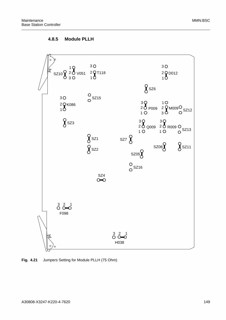
A30808-X3247-K220-4-7620 149
MaintenanceBase Station Controller
MMN:BSC
4.8.5 Module PLLH
Fig. 4.21 Jumpers Setting for Module PLLH (75 Ohm)
SZ4
T11812
3
3V051
12
F098
SZ10 D01212
3
SZ6
SZ15
K08612
3
SZ3
SZ1
SZ2
SZ16
3 2 1
H038
3 2 1
SZ7
SZ05
SZ08 SZ11
1Q009
32
1R009
32
SZ13
SZ121
P009
32
3M009
12
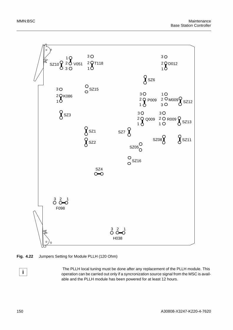
150 A30808-X3247-K220-4-7620
MMN:BSC MaintenanceBase Station Controller
Fig. 4.22 Jumpers Setting for Module PLLH (120 Ohm)
SZ4
T11812
3
3V051
12
F098
SZ10 D01212
3
SZ6
SZ15
K08612
3
SZ3
SZ1
SZ2
SZ16
3 2 1
H038
3 2 1
SZ7
SZ05
SZ08 SZ11
1Q009
32
1R009
32
SZ13
SZ121
P009
32
3M009
12
iThe PLLH local tuning must be done after any replacement of the PLLH module. Thisoperation can be carried out only if a syncronization source signal from the MSC is avail-able and the PLLH module has been powered for at least 12 hours.
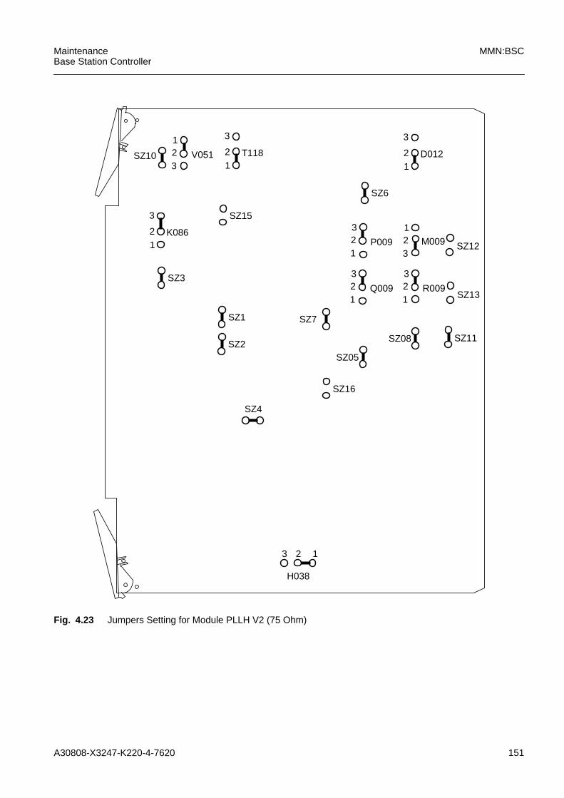
A30808-X3247-K220-4-7620 151
MaintenanceBase Station Controller
MMN:BSC
Fig. 4.23 Jumpers Setting for Module PLLH V2 (75 Ohm)
SZ4
T11812
3
3V051
12SZ10 D012
12
3
SZ6
SZ15
K08612
3
SZ3
SZ1
SZ2
SZ16
H038
3 2 1
SZ7
SZ05
SZ08 SZ11
1Q009
32
1R009
32
SZ13
SZ121
P009
32
3M009
12
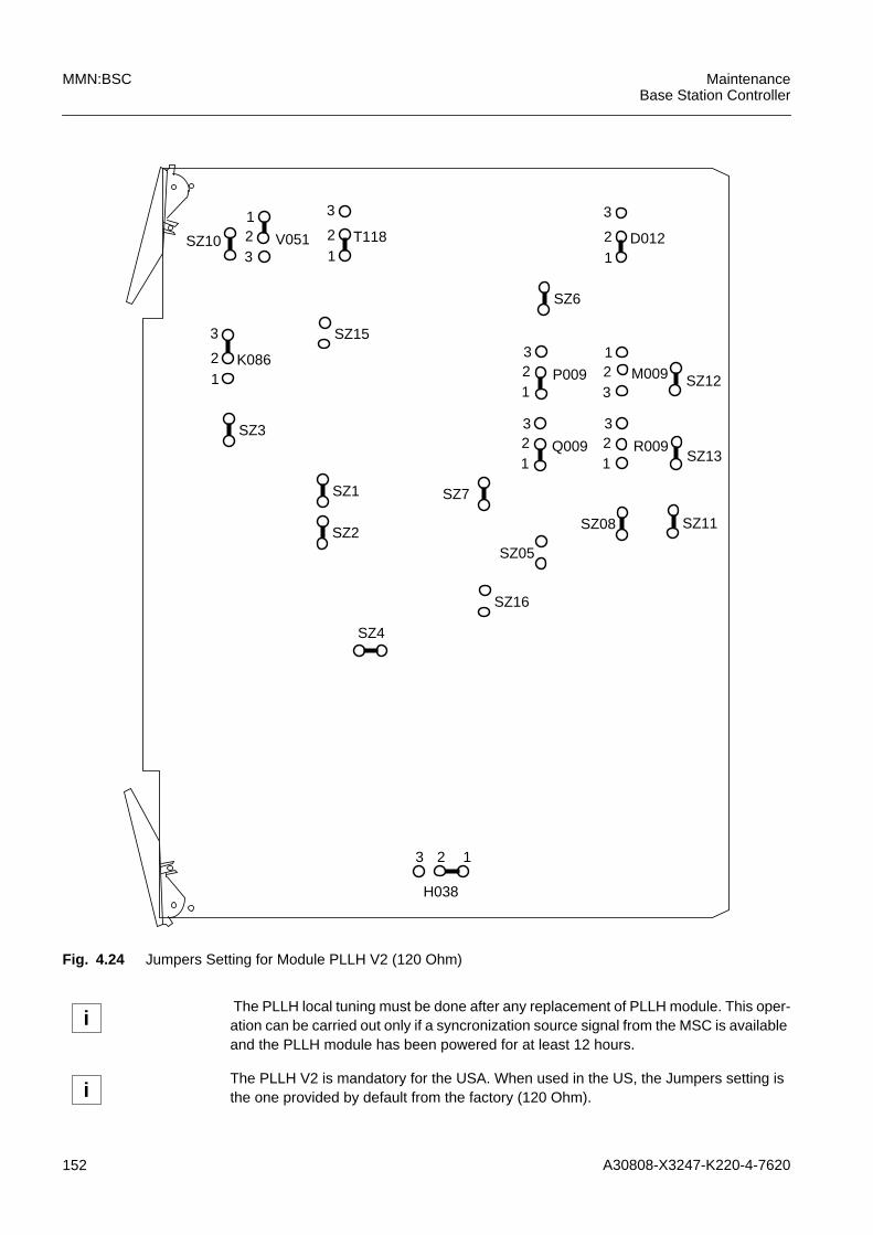
152 A30808-X3247-K220-4-7620
MMN:BSC MaintenanceBase Station Controller
Fig. 4.24 Jumpers Setting for Module PLLH V2 (120 Ohm)
SZ4
T11812
3
3V051
12SZ10 D012
12
3
SZ6
SZ15
K08612
3
SZ3
SZ1
SZ2
SZ16
H038
3 2 1
SZ7
SZ05
SZ08 SZ11
1Q009
32
1R009
32
SZ13
SZ121
P009
32
3M009
12
iThe PLLH local tuning must be done after any replacement of PLLH module. This oper-ation can be carried out only if a syncronization source signal from the MSC is availableand the PLLH module has been powered for at least 12 hours.
iThe PLLH V2 is mandatory for the USA. When used in the US, the Jumpers setting isthe one provided by default from the factory (120 Ohm).
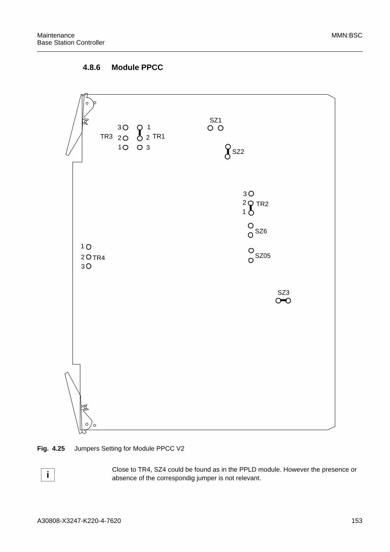
A30808-X3247-K220-4-7620 153
MaintenanceBase Station Controller
MMN:BSC
4.8.6 Module PPCC
Fig. 4.25 Jumpers Setting for Module PPCC V2
SZ3
TR1
12
3
3
TR31
2
SZ2
TR432
1
SZ05
SZ6
1TR2
32
SZ1
iClose to TR4, SZ4 could be found as in the PPLD module. However the presence orabsence of the correspondig jumper is not relevant.
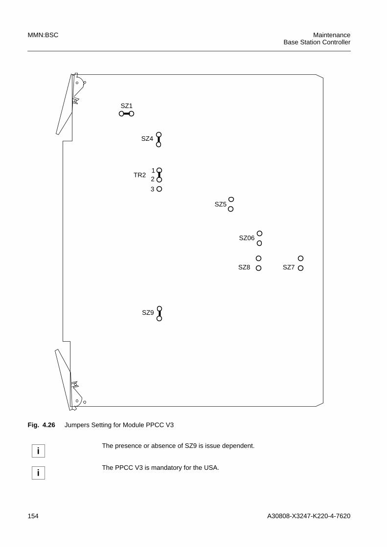
154 A30808-X3247-K220-4-7620
MMN:BSC MaintenanceBase Station Controller
Fig. 4.26 Jumpers Setting for Module PPCC V3
SZ8
SZ4
SZ06
SZ5
3
TR212
SZ1
SZ7
SZ9
iThe presence or absence of SZ9 is issue dependent.
iThe PPCC V3 is mandatory for the USA.
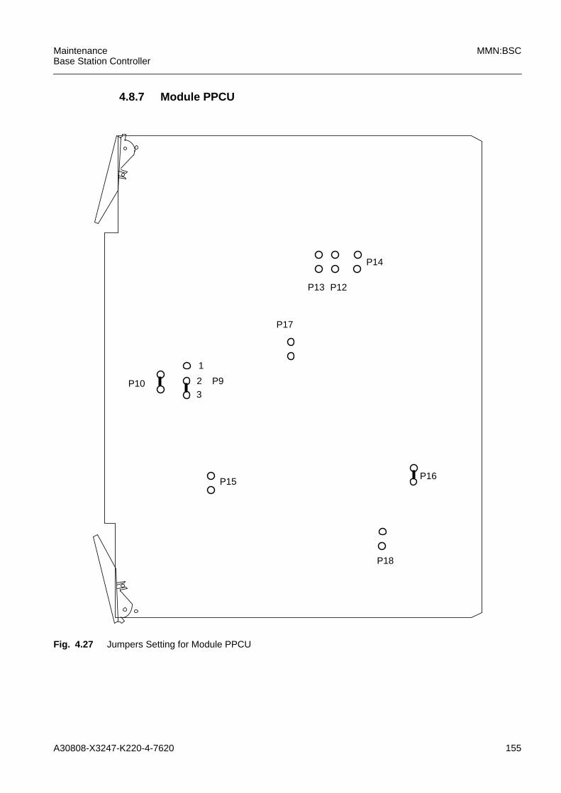
A30808-X3247-K220-4-7620 155
MaintenanceBase Station Controller
MMN:BSC
4.8.7 Module PPCU
Fig. 4.27 Jumpers Setting for Module PPCU
P14
32
1
P18
P16
P12P13
P17
P15
P10 P9
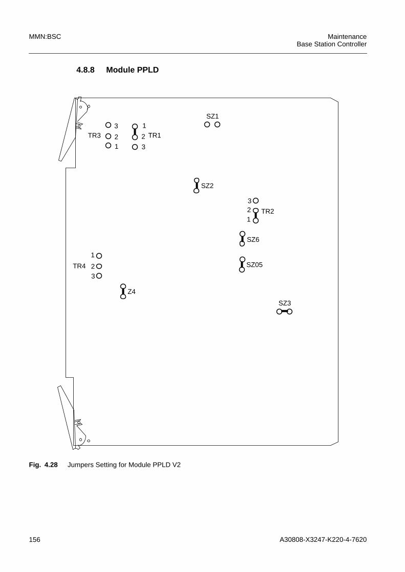
156 A30808-X3247-K220-4-7620
MMN:BSC MaintenanceBase Station Controller
4.8.8 Module PPLD
Fig. 4.28 Jumpers Setting for Module PPLD V2
SZ3
TR1
12
3
3
TR31
2
SZ2
TR4
32
1SZ05
SZ6
1TR2
32
SZ1
Z4
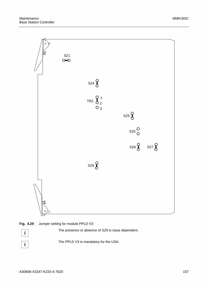
A30808-X3247-K220-4-7620 157
MaintenanceBase Station Controller
MMN:BSC
Fig. 4.29 Jumper setting for module PPLD V3
iThe presence or absence of SZ9 is issue dependent.
iThe PPLD V3 is mandatory for the USA.
TR2
3
1
2
SZ4
SZ5
SZ1
SZ6
SZ8 SZ7
SZ9
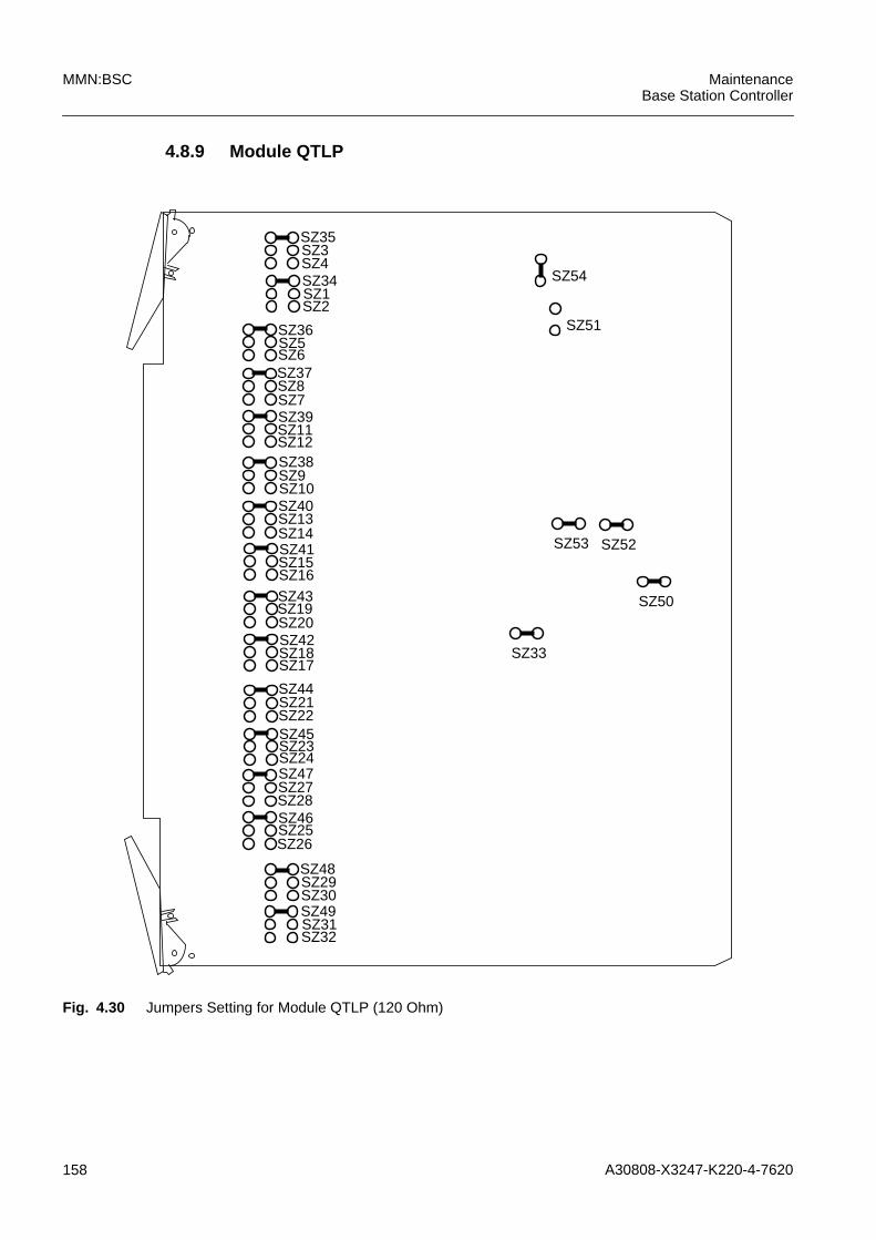
158 A30808-X3247-K220-4-7620
MMN:BSC MaintenanceBase Station Controller
4.8.9 Module QTLP
Fig. 4.30 Jumpers Setting for Module QTLP (120 Ohm)
SZ35SZ3SZ4SZ34SZ1SZ2
SZ36SZ5SZ6SZ37SZ8SZ7
SZ52
SZ39SZ11SZ12SZ38SZ9SZ10
SZ13SZ14
SZ40
SZ41SZ15SZ16SZ43SZ19SZ20SZ42SZ18SZ17
SZ44SZ21SZ22
SZ23SZ24
SZ45
SZ27SZ28
SZ25SZ46
SZ47
SZ26
SZ48SZ29SZ30SZ49SZ31SZ32
SZ54
SZ53
SZ50
SZ33
SZ51
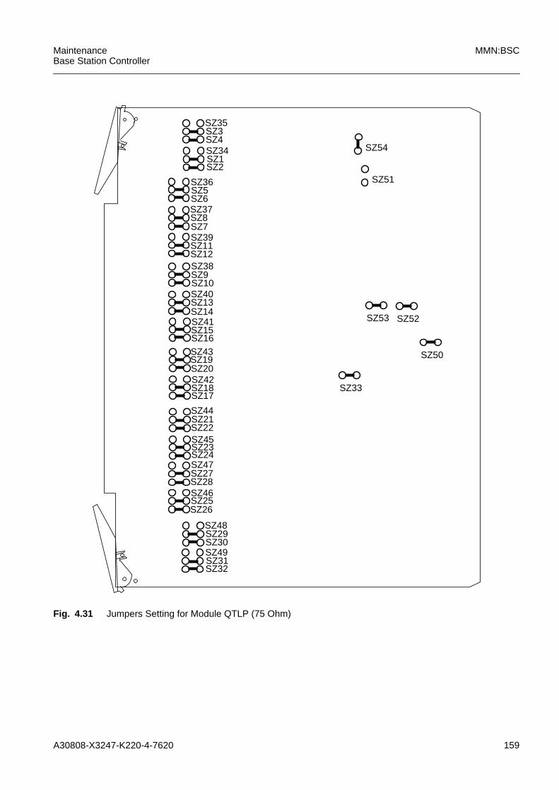
A30808-X3247-K220-4-7620 159
MaintenanceBase Station Controller
MMN:BSC
Fig. 4.31 Jumpers Setting for Module QTLP (75 Ohm)
SZ35SZ3SZ4SZ34SZ1SZ2
SZ36SZ5SZ6SZ37SZ8SZ7
SZ52
SZ39SZ11SZ12SZ38SZ9SZ10
SZ13SZ14
SZ40
SZ41SZ15SZ16SZ43SZ19SZ20SZ42SZ18SZ17
SZ44SZ21SZ22
SZ23SZ24
SZ45
SZ27SZ28
SZ25SZ46
SZ47
SZ26
SZ48SZ29SZ30SZ49SZ31SZ32
SZ54
SZ53
SZ50
SZ33
SZ51

160 A30808-X3247-K220-4-7620
MMN:BSC MaintenanceBase Station Controller
Fig. 4.32 Jumpers Setting for Module QTLP V2 (75 Ohm)
SZ19SZ20 SZ50
SZ2
SZ1
SZ4
SZ3
SZ6
SZ5
SZ8
SZ7
SZ10
SZ9
SZ13
SZ11
SZ15
SZ12
SZ14
SZ17SZ18
SZ24
SZ22SZ21
SZ23
SZ28
SZ26SZ25
SZ27
SZ32
SZ31SZ29
SZ30
SZ36
SZ34SZ33
SZ35
SZ40
SZ39SZ37
SZ38
SZ44
SZ42SZ41
SZ43
SZ48
SZ47SZ45
SZ46
3
21
TR4
3
21
TR5
3
21
TR6
3
21
TR7
3
21
TR8
3
21
TR9
3
21
TR10
3
21
TR11321 TR1
SZ51
SZ16

A30808-X3247-K220-4-7620 161
MaintenanceBase Station Controller
MMN:BSC
Fig. 4.33 Jumpers Setting for Module QTLP V2 (100 Ohm)
SZ19SZ20 SZ50
SZ2
SZ1
SZ4
SZ3
SZ6
SZ5
SZ8
SZ7
SZ10
SZ9
SZ13
SZ11
SZ15
SZ12
SZ14
SZ17
SZ18
SZ24
SZ22
SZ21
SZ23
SZ28
SZ26
SZ25
SZ27
SZ32
SZ31
SZ29
SZ30
SZ36
SZ34
SZ33
SZ35
SZ40
SZ39
SZ37
SZ38
SZ44
SZ42
SZ41
SZ43
SZ48
SZ47
SZ45
SZ46
3
21
TR4
3
21
TR5
3
21
TR6
3
21
TR7
3
21
TR8
3
21
TR9
3
21
TR10
3
21
TR11321 TR1
SZ51
SZ16
iThe QTLP V2 is mandatory for the USA.

162 A30808-X3247-K220-4-7620
MMN:BSC MaintenanceBase Station Controller
Fig. 4.34 Jumpers Setting for Module QTLP V2 (120 Ohm)
On the QTLP module front there are eight plugs to monitor the 2Mbit/s PCM lines (seeFig. 5.14.6). Each line has a monitoring point on both the transmitting side and thereceiving side (see Tab. 5.14.1)
SZ19SZ20 SZ50
SZ2
SZ1
SZ4
SZ3
SZ6
SZ5
SZ8
SZ7
SZ10
SZ9
SZ13
SZ11
SZ15
SZ12
SZ14
SZ17
SZ18
SZ24
SZ22
SZ21
SZ23
SZ28
SZ26
SZ25
SZ27
SZ32
SZ31
SZ29
SZ30
SZ36
SZ34
SZ33
SZ35
SZ40
SZ39
SZ37
SZ38
SZ44
SZ42
SZ41
SZ43
SZ48
SZ47
SZ45
SZ46
32
1TR4
32
1TR5
3
21
TR6
3
21
TR7
3
21
TR8
321
TR9
32
1TR10
32
1
TR11321 TR1
SZ51
SZ16

A30808-X3247-K220-4-7620 163
MaintenanceBase Station Controller
MMN:BSC
Fig. 4.35 PCM Monitoring Points for QTLP and QTLP V2
Two LEDs (yellow and red) are equipped for each PCM line on the QTLP V2 module .A single red LED represents the board status. The function of these LEDs is shown inthe following table:
QTLP
A
B
TXRXTXRX
C
D
TXRXTXRX
E
F
TXRXTXRX
G
H
TXRXTXRX
QTLP
A
B
TXRXTXRX
C
D
TXRXTXRX
E
F
TXRXTXRX
G
H
TXRXTXRX
V2
LED Functions Yellow LED Red LEDLOS (loss of signal) off onLFA or MFA (loss of frame/multiframe) off onBER Upper Threshold Exceeded off onAIS (alarm indication signal) blink blinkRAI (remote alarm indication) on offfaulty module single red LED on
A Line 0, Port A
B Line 0, Port B
C Line 1, Port A
Tab. 4.6 Description of QTLP and QTLP V2 Monitoring Points

164 A30808-X3247-K220-4-7620
MMN:BSC MaintenanceBase Station Controller
D Line 1, Port B
E Line 2, Port A
F Line 2, Port B
G Line 3, Port A
H Line 3, Port B
Tab. 4.6 Description of QTLP and QTLP V2 Monitoring Points

A30808-X3247-K220-4-7620 165
MaintenanceBase Station Controller
MMN:BSC
4.8.10 Module SN16
Fig. 4.36 Jumpers Setting for Module SN16
TR2
TR4
TR1
TR3

166 A30808-X3247-K220-4-7620
MMN:BSC MaintenanceBase Station Controller
4.8.11 Module TDPC
Fig. 4.37 Jumpers Setting for Module TDPC V6
TR16
TRWDT
1
23
TRBF2
TR1
TRMMX
TR_FLASHTR_FW
TR_BIST
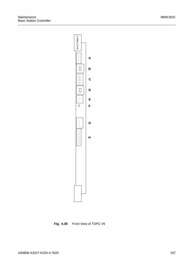
A30808-X3247-K220-4-7620 167
MaintenanceBase Station Controller
MMN:BSC
Fig. 4.38 Front View of TDPC V6
: : : :
: : :
: : :
: :
TDPCV6
A
B
C
D
E
F
G
: : :
H
::::::
::::
. . . .
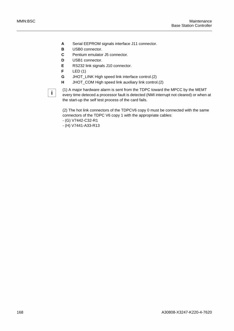
168 A30808-X3247-K220-4-7620
MMN:BSC MaintenanceBase Station Controller
A Serial EEPROM signals interface J11 connector.B USB0 connector.C Pentium emulator J5 connector.D USB1 connector.E RS232 link signals J10 connector.F LED (1)G JHOT_LINK High speed link interface control.(2)H JHOT_COM High speed link auxiliary link control.(2)
i(1) A major hardware alarm is sent from the TDPC toward the MPCC by the MEMTevery time deteced a processor fault is detected (NMI interrupt not cleared) or when atthe start-up the self test process of the card fails.
(2) The hot link connectors of the TDPCV6 copy 0 must be connected with the sameconnectors of the TDPC V6 copy 1 with the appropriate cables:- (G) V7442-C32-R1- (H) V7441-A33-R13

A30808-X3247-K220-4-7620 169
MaintenanceBase Station Controller
MMN:BSC
4.8.12 Module UBEX
Fig. 4.39 Jumpers Setting for Module UBEX
TR1
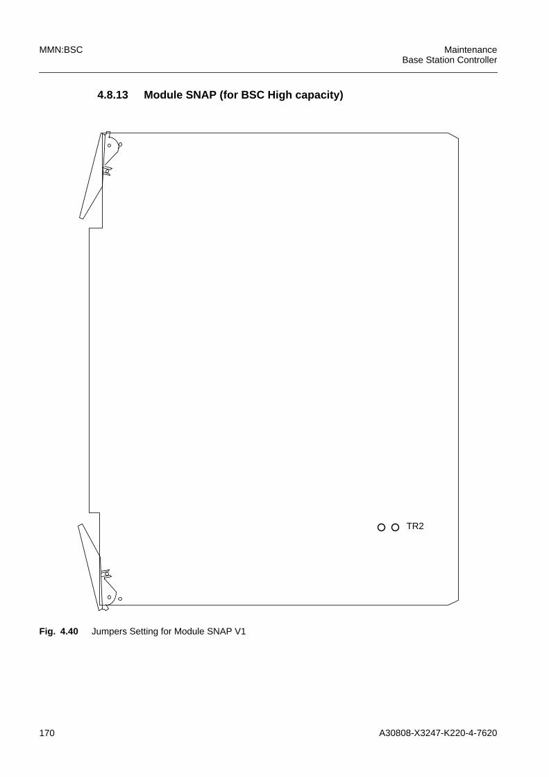
170 A30808-X3247-K220-4-7620
MMN:BSC MaintenanceBase Station Controller
4.8.13 Module SNAP (for BSC High capacity)
Fig. 4.40 Jumpers Setting for Module SNAP V1
TR2

A30808-X3247-K220-4-7620 171
MaintenanceBase Station Controller
MMN:BSC
4.8.14 Module PPXX (for BSC High capacity)
Fig. 4.41 Jumpers Setting for Module PPXX (fed by EPWR power supply card)
P34P35
JJ3JJ2
P13
PP35
0
P41
P40
P42
P14
P4
P38
P36P37
P39
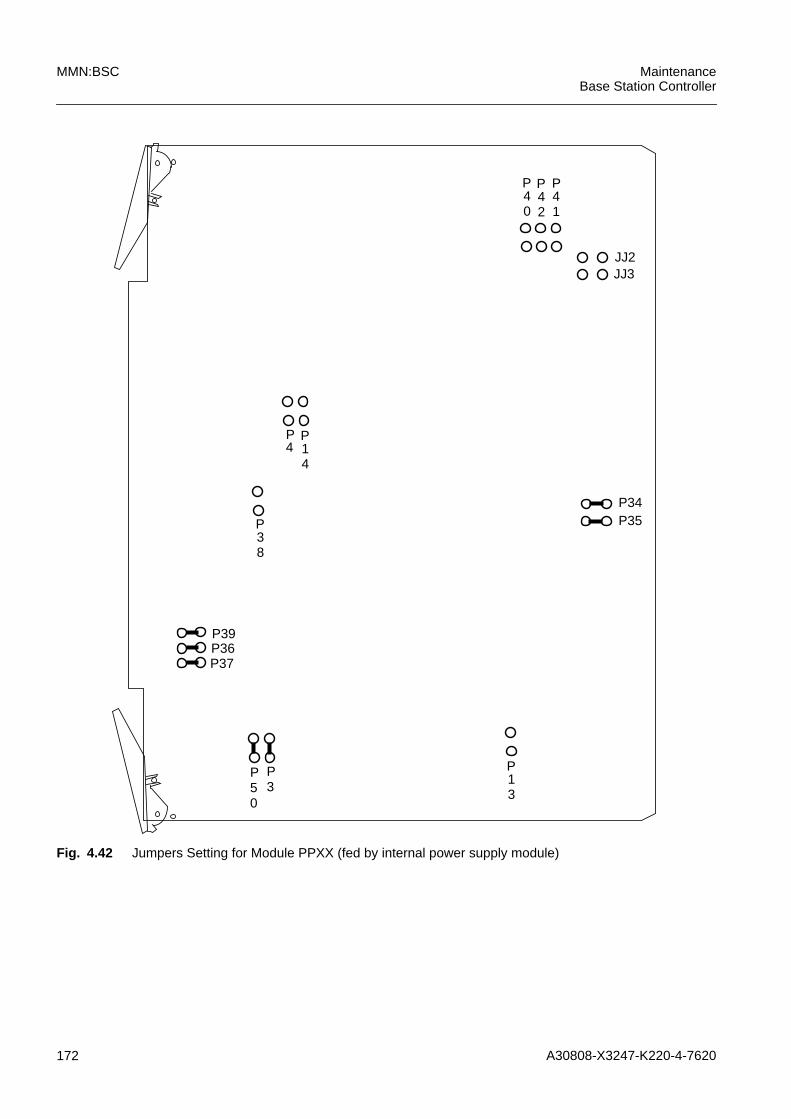
172 A30808-X3247-K220-4-7620
MMN:BSC MaintenanceBase Station Controller
Fig. 4.42 Jumpers Setting for Module PPXX (fed by internal power supply module)
P34P35
JJ3JJ2
P13
PP35
0
P41
P40
P42
P14
P4
P38
P36P37
P39
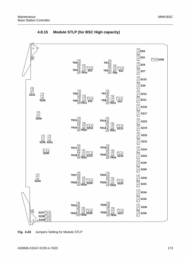
A30808-X3247-K220-4-7620 173
MaintenanceBase Station Controller
MMN:BSC
4.8.15 Module STLP (for BSC High capacity)
Fig. 4.43 Jumpers Setting for Module STLP
SZ6
SZ5
SZ8
SZ7
SZ10
SZ9
SZ11
SZ12
SZ18
SZ17
SZ20
SZ19
SZ22
SZ21
SZ24
SZ23
SZ30
SZ29
SZ32
SZ31
SZ34
SZ33
SZ36
SZ35
SZ60
SZ4TR12
TR7
TR8
SZ13TR21
TR13
TR14
SZ16TR24
TR19
TR20
SZ25TR33
TR25
TR26
SZ27TR35
TR29
TR30
SZ1TR9
TR1
TR2SZ2TR10
TR3
TR4
SZ3TR11
TR5
TR6
SZ14TR22
TR15
TR16
SZ15TR23
TR17
TR18
SZ26TR34
TR27
TR28
SZ28TR36
TR31
TR32
SZ41
SZ45
SZ40
SZ52 SZ51
SZ50
SZ44
SZ37SZ38SZ39

174 A30808-X3247-K220-4-7620
MMN:BSC MaintenanceBase Station Controller
75 Ohm 100 Ohm 110 Ohm 120 Ohm
SZ1 OPENTR9 1:2SZ6 CLOSETR1 1:2TR2 1:2SZ5 CLOSE
SZ1 OPENTR9 2:3SZ6 OPENTR1 2:3TR2 2:3SZ5 OPEN
SZ1 CLOSEDTR9 OPENSZ6 OPENTR1 2:3TR2 2:3SZ5 OPEN
SZ1 OPENTR9 OPENSZ6 OPENTR1 1:2TR2 1:2SZ5 OPEN
SZ2 OPENTR10 1:2SZ8 CLOSETR3 1:2TR4 1:2SZ7 CLOSE
SZ2 OPENTR10 2:3SZ8 OPENTR3 2:3TR4 2:3SZ7 OPEN
SZ2 CLOSEDTR10 OPENSZ8 OPENTR3 2:3TR4 2:3SZ7 OPEN
SZ2 OPENTR10 OPENSZ8 OPENTR3 1:2TR4 1:2SZ7 OPEN
SZ3 OPENTR11 1:2SZ10 CLOSETR5 1:2TR6 1:2SZ9 CLOSE
SZ3 OPENTR11 2:3SZ10 OPENTR5 2:3TR6 2:3SZ9 OPEN
SZ3 CLOSEDTR11 OPENSZ10 OPENTR5 2:3TR6 2:3SZ9 OPEN
SZ3 OPENTR11 OPENSZ10 OPENTR5 1:2TR6 1:2SZ9 OPEN
SZ4 OPENTR12 1:2SZ12 CLOSETR7 1:2TR8 1:2SZ11 CLOSE
SZ4 OPENTR12 2:3SZ12 OPENTR7 2:3TR8 2:3SZ11 OPEN
SZ4 CLOSEDTR12 OPENSZ12 OPENTR7 2:3TR8 2:3SZ11 OPEN
SZ4 OPENTR12 OPENSZ12 OPENTR7 1:2TR8 1:2SZ11 OPEN
SZ13 OPENTR21 1:2SZ18 CLOSETR13 1:2TR141:2SZ17 CLOSE
SZ13 OPENTR21 2:3SZ18 OPENTR13 2:3TR14 2:3SZ17 OPEN
SZ13 CLOSEDTR21 OPENSZ18 OPENTR13 2:3TR14 2:3SZ17 OPEN
SZ13 OPENTR21 OPENSZ18 OPENTR13 1:2TR141:2SZ17 OPEN
SZ14 OPENTR22 1:2SZ20 CLOSETR15 1:2TR16 1:2SZ19 CLOSE
SZ14 OPENTR22 2:3SZ20 OPENTR15 2:3TR16 2:3SZ19 OPEN
SZ14 CLOSEDTR22 OPENSZ20 OPENTR15 2:3TR16 2:3SZ19 OPEN
SZ14 OPENTR22 OPENSZ20 OPENTR15 1:2TR16 1:2SZ19 OPEN
SZ15 OPENTR23 1:2SZ22 CLOSETR17 1:2TR18 1:2SZ21 CLOSE
SZ15 OPENTR23 2:3SZ22 2:3TR17 2:3TR18 2:3SZ21 OPEN
SZ15 CLOSEDTR23 OPENSZ22 2:3TR17 2:3TR18 2:3SZ21 OPEN
SZ15 OPENTR23 OPENSZ22 OPENTR17 1:2TR18 1:2SZ21 OPEN
Tab. 4.7 Jumpers STLP
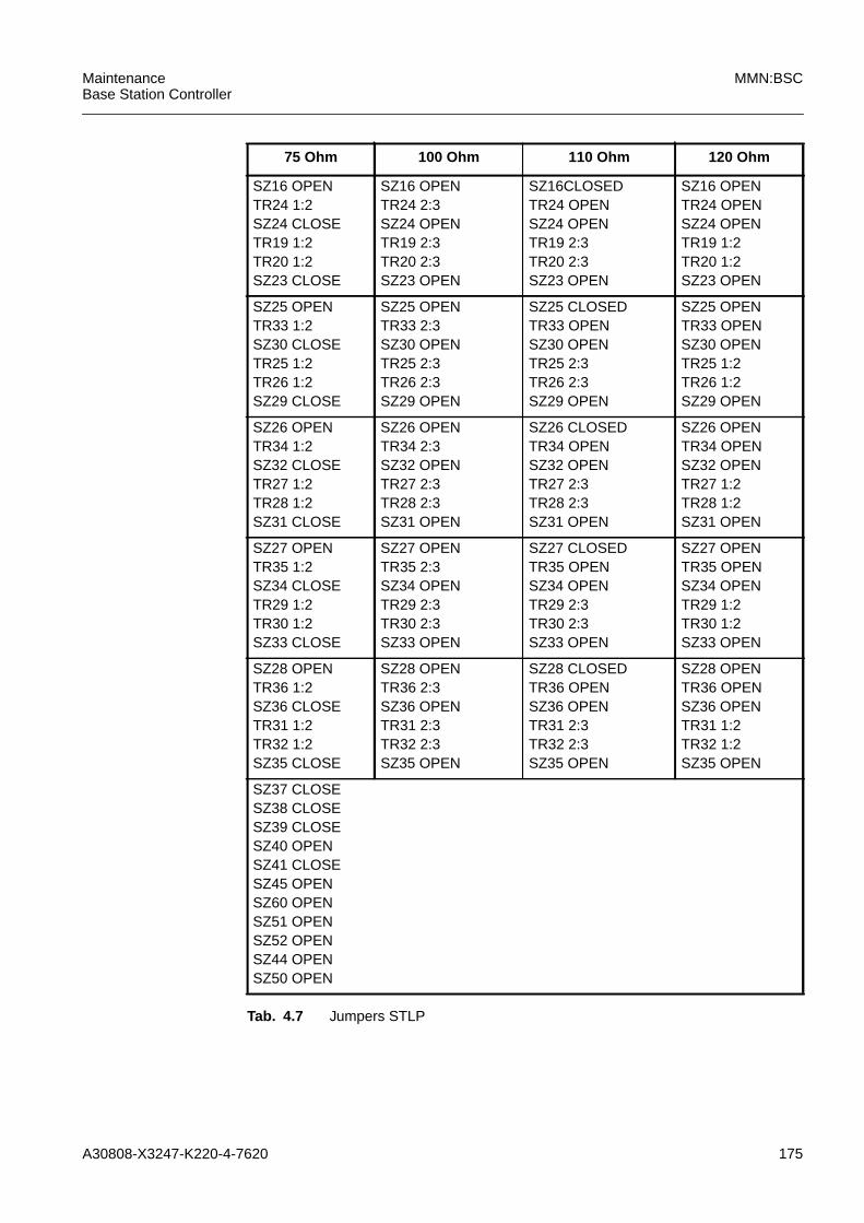
A30808-X3247-K220-4-7620 175
MaintenanceBase Station Controller
MMN:BSC
SZ16 OPENTR24 1:2SZ24 CLOSETR19 1:2TR20 1:2SZ23 CLOSE
SZ16 OPENTR24 2:3SZ24 OPENTR19 2:3TR20 2:3SZ23 OPEN
SZ16CLOSEDTR24 OPENSZ24 OPENTR19 2:3TR20 2:3SZ23 OPEN
SZ16 OPENTR24 OPENSZ24 OPENTR19 1:2TR20 1:2SZ23 OPEN
SZ25 OPENTR33 1:2SZ30 CLOSETR25 1:2TR26 1:2SZ29 CLOSE
SZ25 OPENTR33 2:3SZ30 OPENTR25 2:3TR26 2:3SZ29 OPEN
SZ25 CLOSEDTR33 OPENSZ30 OPENTR25 2:3TR26 2:3SZ29 OPEN
SZ25 OPENTR33 OPENSZ30 OPENTR25 1:2TR26 1:2SZ29 OPEN
SZ26 OPENTR34 1:2SZ32 CLOSETR27 1:2TR28 1:2SZ31 CLOSE
SZ26 OPENTR34 2:3SZ32 OPENTR27 2:3TR28 2:3SZ31 OPEN
SZ26 CLOSEDTR34 OPENSZ32 OPENTR27 2:3TR28 2:3SZ31 OPEN
SZ26 OPENTR34 OPENSZ32 OPENTR27 1:2TR28 1:2SZ31 OPEN
SZ27 OPENTR35 1:2SZ34 CLOSETR29 1:2TR30 1:2SZ33 CLOSE
SZ27 OPENTR35 2:3SZ34 OPENTR29 2:3TR30 2:3SZ33 OPEN
SZ27 CLOSEDTR35 OPENSZ34 OPENTR29 2:3TR30 2:3SZ33 OPEN
SZ27 OPENTR35 OPENSZ34 OPENTR29 1:2TR30 1:2SZ33 OPEN
SZ28 OPENTR36 1:2SZ36 CLOSETR31 1:2TR32 1:2SZ35 CLOSE
SZ28 OPENTR36 2:3SZ36 OPENTR31 2:3TR32 2:3SZ35 OPEN
SZ28 CLOSEDTR36 OPENSZ36 OPENTR31 2:3TR32 2:3SZ35 OPEN
SZ28 OPENTR36 OPENSZ36 OPENTR31 1:2TR32 1:2SZ35 OPEN
SZ37 CLOSESZ38 CLOSESZ39 CLOSESZ40 OPENSZ41 CLOSESZ45 OPENSZ60 OPENSZ51 OPENSZ52 OPENSZ44 OPENSZ50 OPEN
75 Ohm 100 Ohm 110 Ohm 120 Ohm
Tab. 4.7 Jumpers STLP

176 A30808-X3247-K220-4-7620
MMN:BSC MaintenanceBase Station Controller

A30808-X3247-K220-4-7620 177
MaintenanceBase Station Controller
MMN:BSC
5 Appendix
5.1 Alarm Handling
An alarm notifies the Operation and Maintenance Center (OMC) of fault conditions.Alarms can occur at any point in the BSC subsystem provided with a hardware (hard-ware) or software (SW) detector to recognize the fault, and with an event-generatingsoftware.
Following the general alarm philosophy, alarm reports specify:
– the fault severity level;
– the anomaly type.
Fault Severity Levels
The BSC subsystem provides five different severity levels:
– Critical ;
– Major ;
– Minor ;
– Warning ;
– Cleared .
The Critical level is reached when the subsystem is out of order.
The Major level specifies the presence in the subsystem of a fault that makes thesubsystem itself drop significantly. The immediate intervention of an operator is requiredto clear the fault and resume the service.
The Minor level specifies that the fault in the subsystem does not lower its functionality(for instance, the backup unit is not working). In other words, a section of the subsystemis lowered, but it is still able to work without effects on the service. Operator interventionis required, but it is not urgent, either because the quality of the service is still acceptableor because an automatic reconfiguration has been made.
The Warning level specifies the presence within the subsystem of an error that does notcause traffic or hardware failure.
The Cleared level specifies that a previous error condition is now cleared.
Anomaly Types
Five types of anomalies are defined, depending on the functional part of the subsystemthat is actually damaged:
– Quality of Service
– Communication
– Equipment
– Processing
– Environment
A Quality of Service alarm refers to a service downgrading. Such an alarm is gener-ated, for instance, from the level 3 radio when the quality of the service provided to themobile user drops to the attention threshold.
178 A30808-X3247-K220-4-7620
MMN:BSC MaintenanceBase Station Controller
Communication alarms refer to the procedures/processes that are devoted to thecommunication exchange between subsystem elements. Generally speaking, thefollowing failures are taken into account:
– system link (SS7, LAPD, X.25) faults;
– faults of the connection network that do not originate from the hardware;
– level 3 radio anomalies.
Equipment alarms refer to hardware failures. Alarms of this kind are notified and anal-ized by the maintenance procedures in order to clear them by means of the providedredundancy. In this case, the alarm display reports the generating function together withthe related severity.
With each of these types of anomolies, software tails (System Tails) are associated thatcontain a brief outline description of various error messages relating to the errorconcerned.
Processing alarms refer to software faults; they could be just warning messages whenthey do not cause failure, otherwise they can generate a reload of the software on theboard.
Environment alarms are associated with environmental events such as fire, water andso on.

A30808-X3247-K220-4-7620 179
MaintenanceBase Station Controller
MMN:BSC
5.2 Alarm Reporting
Every system of the PLMN network reports any malfunction occurring in its operation toa local operator and to a remote control center (OMC) . These malfunctions include alarge variety of types, from hardware faults to recurrent software errors and from aircondition faults to back-up battery faults.
The BSC system is a network element of the PLMN and can be remotely controlled viathe OMC, therefore the Alarm Reporting activity, by means of which the BSC keepsOMC informed on its own malfunction-related events, plays a key role. In the BSC, theAlarm Reporting function has been developed taking into account the specific peculiar-ities of this equipment.
The SBS BSC Alarm Reporting feature handles two different event types: fault detec-tion and fault ceased detection .
The fault detector detects a fault and sends:
1. The related alarm message to alarm reporting.This task extracts information from the centralized data base, sends the "OutputMessage" to OMT/LMT and, if needed, sends a message to the status handler torequest a state change of the object generating the alarm and an alarm panelupdate.
2. The related alarm ceased message to alarm reporting.As in the previous case, this block forwards the message to OMC/LMT, activates thestatus handler if needed and deletes the ceased alarm from the internal queue.
The State used on the SBS-BSC system is derived from the one proposed by GSM stan-dards. The model used includes three fields as follow:
ADMINISTRATIVE STATE: is the only state that the operator can alter by usingmaintenance commands.
LOCKED: the object is not allowed to perform its functions withoutthe intervention of the operator.
UNLOCKED: the object can freely perform all of its functions.SHUTTING_DOWN: the object is graduaully changing its administrative state
from UNLOCKED to LOCKED.
OPERATIONAL STATE: is used to indicate whether an object is able to work ornot. It specifies the object's operability.
ENABLED: the object is in service. It may be used or not, dependingon system needs.
DISABLED: the object is out of service. It cannot be used to performits operations.
USAGE STATE: is used to describe the object’s current use. It may besplit into the following three groups of logically indepen-dent values.
IDLE: In this state, the object is not currently in use.BUSY: In this state, the object is completely used.ACTIVE: In this state,the object is partially used.
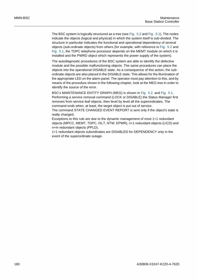
180 A30808-X3247-K220-4-7620
MMN:BSC MaintenanceBase Station Controller
The BSC system is logically structured as a tree (see Fig. 5.2 and Fig. 5.1). The nodesindicate the objects (logical and physical) in which the system itself is sub-divided. Thestructure in particular indicates the functional and operational dependency of severalobjects (sub-ordinate objects) from others (for example, with reference to Fig. 5.2 andFig. 5.1, the TDPC telephone processor depends on the MEMT module on which it isinstalled and the PWRD object which represents the power supply of the system).
The autodiagnostic procedures of the BSC system are able to identify the defectivemodule and the possible malfunctioning objects. The same procedures can place theobjects into the operational DISABLE state. As a consequence of this action, the sub-ordinate objects are also placed in the DISABLE state. This allows for the illumination ofthe appropriate LED on the alarm panel. The operator must pay attention to this, and bymeans of the procedure shown in the following chapter, look at the MEG tree in order toidentify the source of the error.
BSC's MAINTENANCE ENTITY GRAPH (MEG) is shown in Fig. 5.2. and Fig. 5.1.Performing a service removal command (LOCK or DISABLE) the Status Manager firstremoves from service leaf objects, then level by level all the superordinates. Thecommand ends when, at least, the target object is put out of service.The command STATE CHANGED EVENT REPORT is sent only if the object's state isreally changed.Exceptions to this rule are due to the dynamic management of most 1+1 redundantobjects (MPCC, MEMT, TDPC, IXLT, NTW, EPWR), n+1 redundant objects (LICD) andn+m redundant objects (PPLD).1+1 redundant objects subordinates are DISABLED for DEPENDENCY only in theevent of the superordinate outage.

A30808-X3247-K220-4-7620 181
MaintenanceBase Station Controller
MMN:BSC
Fig. 5.1 The BSC Maintenance Entity Graph (MEG tree) for BSC Regular Capacity
When an LICD is put out of service the PCM lines created on the above circuits areDISABLED only if the associated spare module (LICDS-0 for LICD-0 and LICD-1,LICDS-1 for the others LICD) is out of service or is already providing service.
The Fig. 5.2 shown the MEG for BSC high capacity.
PWRD
MPCC MEMT DK40 IXLT NTW
PPCC
TDPC
PPLD
DISK
EPWR
LICDS
PCMB
LPDLRLPDLMLPDLS
TRAU BTSM
PCMA BTSSYNC
TSLATRX
CHAN
LICD
OMAL
ONLY IF IN EXTENDED RACK
SS7L X25D X25A
CBCL
NUC
PPCU
PCMGPCMS
PTPPKF
FRL
NSVC
PCU
ONLY IF TCH or TCHSD
SS7SBSC
CTRCO
CTRSCHED
ENVATRACEBSCESUSW
GPRSTRX
BSCESUDB NEYESUSW RSUSWLH SYNE
RSUEXE RSUPCH RSUDB REMIN SCA
SCAN_BSC SCAN_BTS SCAN_BTSLHDO SCAN_BTSOHDOINT SCAN_BTSOHDONGH SCAN_SS7L SCAN_BTSM
CHAN

182 A30808-X3247-K220-4-7620
MMN:BSC MaintenanceBase Station Controller
Fig. 5.2 The BSC Maintenance Entity Graph (MEG tree) for BSC High Capacity

A30808-X3247-K220-4-7620 183
MaintenanceBase Station Controller
MMN:BSC
5.3 Failure Event Message
This type of message is sent to the I/O device (OMT and/or LMT), if any exist, when anerror occurs. The message is formatted taking information, partly from the messagereceived from the error collector and partly from the protected database of the ErrorTask. More specifically, the failure event message to be sent to the I/O module (in otherwords to the OMT and/or to the LMT) will include the following information:
Date/TimeNAMEEvent TypeEvent TimeProbable CauseSpecific ProblemsSeverityTrend IndicationNotification IdentifierCorrelated Notification
IdentifierRelated MO
Proposed Repair ActionsAdditional TextOriginatorAdditional WordsSoftware Version
Here is a description of the above information.NAME: <object mnemonic+object address>
This field identifies the object. Note that the mnemonic isfollowed by a structured numbering (address) that univocallyidentifies an object in the BSC.
- Event Type: this parameter categorizes the alarm. Five basic categories ofalarm are specified:
Communication Failure Event (COM LED) : a failure event of this typeconcerns the procedure and/or processes that are used to transport informa-tion from one point to another. In principle, the following communicationfailure event is communicated: malfunctions related to all links of the BSCsystem (SS7, LAPD and X.25); problems resulting in blocking the switchingnetwork (not due to hardware causes); and malfunctions resulting in blockingof at least one level 3 radio function. These malfunctions are generated bythe protocols of their respective links whenever they detect a problem, by thelevel 3 radio function and/or by the function controlling the network connec-tions whenever a block is detected in call establishment.According to this definition, for example, the objects of the protocol links andthe level 3 radio manager object are objects generating this failure event.
184 A30808-X3247-K220-4-7620
MMN:BSC MaintenanceBase Station Controller
Quality of Service Events (QOS LED) : a failure event of this type concernsthe degradation of the quality of service in the BSC. Such a failure event willbe generated by level 3 radio whenever the quality of service offered to themobile user drops below the preset warning threshold. It is not easy to iden-tify the objects that could generate such a failure event, because they don'tmake reference to any specific physical object.For example, the process that manages level 3 radio could be regarded asthe object that can generate this type of event. Together with the event, thestatus of the function that experienced the abormal situation could also bespecified.Equipment Failure Events (EQP LED) : an event of this type is associatedwith hardware faults and is the most traditional form. It appears in the form ofhardware malfunctions that are reported and analyzed by the maintenanceprocedures in order to take the necessary remedies based on the redundan-cies which the BSC system is equipped with. As far as the local display isconcerned, for these failure events information on their severity are given aswell as information enabling the location of the faulty unit that generatedthem.For example, there is a lamp to indicate a network unit (the NTW LED) andanother one to indicate an LICD line module unit (the LINE LED), andanother to indicate the processing units. All of these failures are equipmentfailure events and, for every unit, the object shall select the related lamp.Processing Failure Event: this category of failure events includes all soft-ware-type errors. These errors are due to programming errors. These failureevents and the information reported by them are necessary to remove theerror.Environmental Failure Events (ENV LED): this type of failure event isassociated with environmental problems on the site where the BSC islocated. The BSC has the capabilty of detecting these causes via a numberof sense points connected to environmental sensors.
Event Time: This attribute identifies the time of detection of the fault.ProbableCause:
This parameter defines further qualifications as to the probablecause of the alarm.
SpecificProblem:
This Failure Event attribute provides further refinement to the“Probable Cause” attribute.
Severity: this parameter defines five severity levels. The five levels, fromthe least to most severe, are:
Cleared: this severity level indicates the clearing of one or more previouslyreported alarms. This alarm clears all alarms for this managed object thathave the same Alarm Type and Probable Cause. It is reported as an "ErrorCeased Message".Warning: this level indicates that the object has reported a potential orpending "error" that has not yet affected the functionality of the BSC. It is justa prompt to take the necessary actions to diagnose and correct the problemas soon as possible before it becomes more severe. For a failure event ofsuch a low severity, an end-of-alarm event might be unnecessary; in anycase, neither the status nor the instance having generated it are retained (itcould not be polled by OMC), nor will it be displayed by any visual indicator(i.e., LEDs).
A30808-X3247-K220-4-7620 185
MaintenanceBase Station Controller
MMN:BSC
Minor: this level indicates that the object has reported an error that does notdegrade functionality (for example, its backup has been switched intoservice) or, better, indicates that a functional part of the BSC is degraded,but is still in a position to perform its functions without significantly affectingthe service.Major: this level indicates that the object has reported such an error as torender it severly degraded or, better, indicates that a functional part of theBSC system is severly degraded.Critical: this level indicates that the object reported such an error as to put ittotally out of service or, better, indicates that a functional part of the BSC iscompletely unavailable.
- Trend Indica-tion:
this parameter indicates how the degradation of the features ofa component part of the system is evolving, following themalfunction just reported. Its value can be the followings:the Not Applicable trend indication is printed if the associatedseverity for the object in question is INDETERMINATE orWARNING.the NoChange trend indication is printed if the associatedseverity for the object in question isn’t changed from theseverity of those associated to previously reported FailureEvent relevant the same object and still active (i.e. no relatederror ceased message was generated).the LessSevere trend indication is printed if the associatedseverity for the object in question is less severe of the severityof those associated to previously reported Failure Events rele-vant the same object and still active (i.e. no related error ceasedmessage was generated).the LessSevere-noChange trend indication is printed if theassociated severity for the object in question is less severe or ofequal severity of those associated to previously reported FailureEvents relevant the same object and still active (i.e. no relatederror ceased message was generated).the MoreSevere trend indication is printed if the associatedseverity for the object in question is more severe of those asso-ciated to previously reported Failure Events relevant the sameobject and still active (i.e. no related error ceased message wasgenerated).
- NotificationIdentifier:
this attribute identifies unambiguously the Failure Event.
CorrelatedNotification:
this attribute identifies the notification to which this Failure Eventis considered to be correlated. Since the failure Event Reportsare “father event” for the Notification Identifier correlations, theCorrelated Notification information are shown only for theFailure Enet Report output during an Alarm Alignment (OMC) ora Get Pending Alarm Command (LMT)
ProposedRepairActions:
this attribute identifies the repair action suggested to the oper-ator for the fault resolution.

186 A30808-X3247-K220-4-7620
MMN:BSC MaintenanceBase Station Controller
AdditionalText:
For the alarms generated by the ENVA objects, the operatorshall be able to define “his own alarm text” and also to define“the severity associated to each ENVA” objects instanceindipendent from the alarm text. The Additional Text stringdefined by the operator represents a description of the environ-mental event. This field is always present in a Failure EventReport, but is meaningful only for the ENVIRONMENTALFailure Events: in all other type of failure events is output as“Null String”.
Originator: It is an integer number that identifies the software module origi-nating the Failure Event.
- AdditionalWords:
aaaa-oooo are hex values that are helpful for a detailed descrip-tion of the error. This part is of particular usefulness for the soft-ware designer to analyse the error cause and so take properactions to solve the problem.
- SoftwareVersion:
It’s the BSC software version files (if we are on BSC LocalTerminal).
The following is a real example of error message:ALARM REPORTING --> SYSTEM BROADCAST16:00:03 17/02/200021:34:24 17/02/2000*** INFORMATION ***FAILURE EVENT REPORT:
NAME=DISK:1Event Type = Equipment Failure EventEvent Time = 17/02/2000 16:00:03Probable Cause: Disk ProblemSpecific Problems = 181-DISK not AlignedSeverity: MajorTrend Indication: More SevereNotification Identifier = 05Proposed Repair Actions = 1 NoActionAdditional Text = Null StringOriginator: 4305Additional Words =H’003c H’0335 H’0000 H’0000 H’0000H’0000 H’0000 H’0000 H’0000 H’0000H’0000 H’0000 H’0000 H’0000 H’0000Additional Info:Software Version: 02-06-01-01-00-00_10-05-00
A30808-X3247-K220-4-7620 187
MaintenanceBase Station Controller
MMN:BSC
5.4 General diagnostic structure
When the operator enters an asyncronous test command from Local MaintenanceTerminal or O&M Center, or the system itself automatically diagnoses a device, twoactivities are performed: a "status consistency check" and a "phase controller activa-tion". The former involves the initial conditions control, while the latter is involved inmonitoring the execution of the diagnosis sections called "phases".
A diagnostic is subdivided into phases: the single phase is a test on hardware sectionfunctionality. It can be executed individually and can provide an indication of what theproblem is as precisely as possible.
The result of the phase considers both the particular hardware components inspectedby the phase and the general interface of the diagnostic tests.
Some phases will be always present and common to all diagnostics:
The other hardware diagnostic phases are referred to as "working phases". They arecontainers for the group of test routines forcing the single function, the single alarm or aparticular internal hardware interface.The soft termination, contrary to the abort termination, has an operator origin, and canhave two managements: if the diagnosis is still waiting for activation, an immediatecancellation of the asynchronous test request is enough, while if the diagnosis is alreadyactive, the current working phase is completed and the end phase is executed.
The target units considered as maintenance objects on BSC for a generic diagnostic testare as follows:
– PWRS (power supplies)
– MPCC (microprocessor control complex)
– TDPC (telephonic and distributor processor circuit)
– MEMT (memory of TDPC and DUAL PORT Memory between MPCC and TDPC)
– NTW (cross connection network, composed of three elements: PLLH, SN andUBEX)
– PPLD (peripheral processors for LAPD protocols)
– PPCC (peripheral processors for CCS#7 protocols)
– PPCU (peripheral packet Control Unit)
– LICD (line card)
– LICDS (line card spare)
– DK40 (led alarm panel control)
– DISK (physical disk)
– PPXL (peripheral processor LAPD/SS7
– PPXU (peripheral processor used at PPCU evolution)
– IXLT (interface X25 and bcal terminal)
start phase to correctly set the card to support the rest of diagnostic tests;end phase: to restore working conditions of the hardware to the previously
executed phase.it will be always performed as the last phase, unless an abortoccurred, and if the termination is induced by an operator.
abort phase: resets the hardware without depending on what was currentlyexecuted. Its actions depend on the running phase.
188 A30808-X3247-K220-4-7620
MMN:BSC MaintenanceBase Station Controller
From a maintenance point of view, the primary advantage of the diagnosis feature is thecapability to provide a list of the suspected modules at once. Up to four modules can belisted as the possible origin of any fault. This is important in the event of fault of thenetwork (NTW) object. This is the only case in which the correspondence between thelogical and the physical objects involved is not immediately clear. Another aspectconcerns the capability of the diagnosis to provide information about the specific compo-nents on the module responsible for the fault. Although this information is not immedi-ately readable, it is contained in the additional info field reported by the test output.
5.4.1 Hardware Diagnostics
Introduction
Diagnostics are provided to check the functionality of hardware units and to locate hard-ware faults.
They achieve this by:
a) applying inputs to a hardware device;
b) comparing resulting outputs with expected outputs;
c) using the failing phase as the basis for fault resolution;
A diagnostic can be triggered by the following events:
a) manual request to test a particular device (typically during the repair or installationprocedure);
b) system request in case the system wants to start a diagnostics on a device declaredfaulty: if the diagnostic passes, the device is carried back in service; if it fails, thedevice is left out of service.
Every diagnostic is structured in the same way: it is divided into PHASES and eachphase into TESTS.
A TEST is a software routine that verifies the functionality of a specific hardware circuit.
A PHASE is a stand alone set of test routines, executed in a sequential manner, thatverify the same hardware device.
Every diagnostics must have:
– a "start phase" to correctly initialize the device to be tested;
– an "end phase" to re-establish the conditions in which the device was before thediagnostic;
– an "abort phase" to clean up the system configuration in case of an abort of the diag-nostics;
– a variable number of "working phases" (the core of any diagnostic); each workingphase has been designed to point out a least replaceable unit (LRU).
As general rule:
– each diagnostics is destructive (the object has to be locked before starting a test)with the exception of the PWRS;
– the diagnostics of a specific board is incompatible with the diagnostics of the sametype of board (i.e., the diagnostics of LICD-0 is incompatible with the diagnostics ofLICD-1);
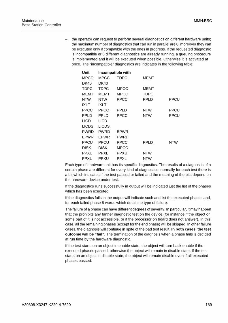
A30808-X3247-K220-4-7620 189
MaintenanceBase Station Controller
MMN:BSC
– the operator can request to perform several diagnostics on different hardware units;the maximum number of diagnostics that can run in parallel are 8, moreover they canbe executed only if compatible with the ones in progress. If the requested diagnosticis incompatible or 8 different diagnostics are already running, a queuing procedureis implemented and it will be executed when possible. Otherwise it is activated atonce. The “incompatible” diagnostics are indicates in the following table:
Each type of hardware unit has its specific diagnostics. The results of a diagnostic of acertain phase are different for every kind of diagnostics: normally for each test there isa bit which indicates if the test passed or failed and the meaning of the bits depend onthe hardware device under test.
If the diagnostics runs successfully in output will be indicated just the list of the phaseswhich has been executed.
If the diagnostics fails in the output will indicate such and list the executed phases and,for each failed phase 8 words which detail the type of failure.
The failure of a phase can have different degrees of severity. In particular, it may happenthat the prohibits any further diagnostic test on the device (for instance if the object orsome part of it is not accessible, or if the processor on board does not answer). In thiscase, all the remaining phases (except for the end phase) will be skipped. In other failurecases, the diagnosis will continue in spite of the bad test result. In both cases, the testoutcome will be “fail” . The termination of the diagnosis when a phase fails is decidedat run time by the hardware diagnostic.
If the test starts on an object in enable state, the object will turn back enable if theexecuted phases passed, otherwise the object will remain in disable state. If the teststarts on an object in disable state, the object will remain disable even if all executedphases passed.
Unit Incompatible withMPCC MPCC TDPC MEMTDK40 DK40TDPC TDPC MPCC MEMTMEMT MEMT MPCC TDPCNTW NTW PPCC PPLD PPCUIXLT IXLTPPCC PPCC PPLD NTW PPCUPPLD PPLD PPCC NTW PPCULICD LICDLICDS LICDSPWRD PWRD EPWREPWR EPWR PWRDPPCU PPCU PPCC PPLD NTWDISK DISK MPCCPPXU PPXL PPXU NTWPPXL PPXU PPXL NTW

190 A30808-X3247-K220-4-7620
MMN:BSC MaintenanceBase Station Controller
5.4.2 Phase Identifier
In order to provide a better interpretable information, the following table shows at theOperator, in the form of character strings, new Phase Identifiers that are specific for thehardware object under test. The Phase Identifier are defined starting from the currentWorking Phase.
In general, when a phase fails the next ones are skipped. In some cases, depending onthe hardware architecture of the board under test, a phase can be carried on even if theprevious one has failed. The phases that have this characteristic are marked with an *.
MOT New Phase Identifier Old Phase
PPCC Preliminary Tests Start Phase
Memory Test* WP1
LCS7 Test* WP2
Loopback Test* WP3
R/W Loopback Register test* WP4
Force Alarm test* WP5
Alarm Test (TDPC side)* WP6
End Test End Phase
PPLD Preliminary Tests Start Phase
Memory Test* WP1
HSCX Test* WP2
Loopback Test* WP3
R/W Loopback Register test* WP4
Force Alarm Test* WP5
Alarm Test (TDPC side)* WP6
End Test End Phase
PPCU Preliminary Tests Start Phase
MPCC and TDPC DUAM Test* WP1
ABIC Test* WP2
GBIC software Test* WP3
End Test End Phase
IXLT Accessibility Tests Start Phase
Address Bus Test* WP1
Alarm Register Test* WP2
DUAM Test* WP3
firmware Internal Test* WP4
Tab. 5.1 New Phase Identifiers
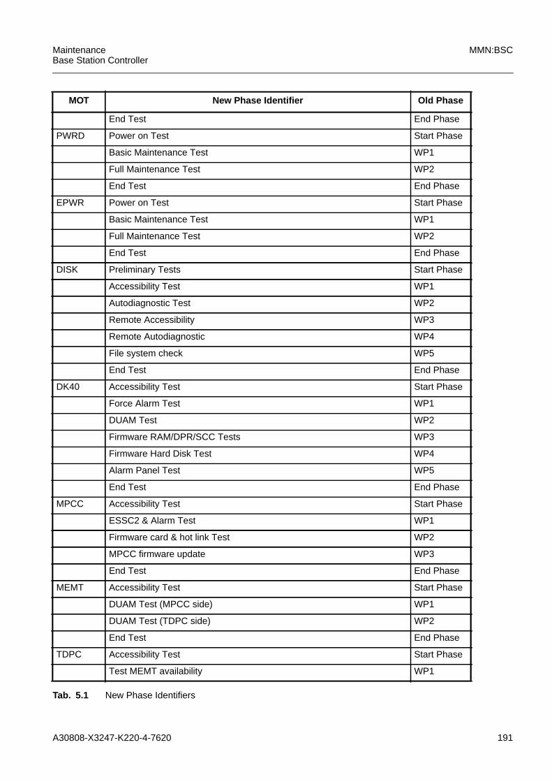
A30808-X3247-K220-4-7620 191
MaintenanceBase Station Controller
MMN:BSC
End Test End Phase
PWRD Power on Test Start Phase
Basic Maintenance Test WP1
Full Maintenance Test WP2
End Test End Phase
EPWR Power on Test Start Phase
Basic Maintenance Test WP1
Full Maintenance Test WP2
End Test End Phase
DISK Preliminary Tests Start Phase
Accessibility Test WP1
Autodiagnostic Test WP2
Remote Accessibility WP3
Remote Autodiagnostic WP4
File system check WP5
End Test End Phase
DK40 Accessibility Test Start Phase
Force Alarm Test WP1
DUAM Test WP2
Firmware RAM/DPR/SCC Tests WP3
Firmware Hard Disk Test WP4
Alarm Panel Test WP5
End Test End Phase
MPCC Accessibility Test Start Phase
ESSC2 & Alarm Test WP1
Firmware card & hot link Test WP2
MPCC firmware update WP3
End Test End Phase
MEMT Accessibility Test Start Phase
DUAM Test (MPCC side) WP1
DUAM Test (TDPC side) WP2
End Test End Phase
TDPC Accessibility Test Start Phase
Test MEMT availability WP1
MOT New Phase Identifier Old Phase
Tab. 5.1 New Phase Identifiers

192 A30808-X3247-K220-4-7620
MMN:BSC MaintenanceBase Station Controller
5.4.3 PWRS Diagnostics
From a hardware point of view the four power supplies in the BSC Rack are namedPWRS modules. From a software point of view (LMT interface) the power supplies in theBSC Rack are named:
– PWRD 0..1 (PWRS modules for the Base Rack)
– EPWR 0..1 (PWRS modules for the Extension Rack)
Test Alarm circuit via MEMT WP2
Test Alarm circuit via TDPC WP3
End Test End Phase
NTW Accessibility Tests* Start Phase
UBEX Force Alarm Test WP1
PLLH Force Alarm Test WP2
PLLH Firmware Self Test WP3
SN Force Alarm Test WP4
SN Speech RAM Address Parity Test WP7
SN Speech RAM Data Parity Test WP8
SN Control RAM Data Parity Test WP9
SN channel loop-test WP10
End Test End Phase
LICD Accessibility Test and card reset Start Phase
Firmware protocol and processor Test WP1
Firmware Self Test* WP2
Check Alarm Status WP3
End Test End Phase
PPXL Board reset and FW self-test Start Phase
MPCC and TDPC DUAM tests WP1
Internal circuit testAccess test WP2
End Test End Phase
PPXU Board reset and FW self-test Start Phase
MPCC and TDPC DUAM tests WP1
Internal circuit testAccess test WP2
ABIC Test WP3
End Test End Phase
MOT New Phase Identifier Old Phase
Tab. 5.1 New Phase Identifiers

A30808-X3247-K220-4-7620 193
MaintenanceBase Station Controller
MMN:BSC
The BSC power supply provides two regulated power voltages (+5,3V and +12,3V) withline regulation of about 2%; the DC input voltage can be an unregulated office batteryranging from -36V to -72V.
The PWRS diagnostics have been implemented with two working phases (see para-graph 5.4.2).
a) PWRS diag start phaseThis phase verifies that Power is on (meaningful only for PWRD card).OUTPUT if start phase fails:No additional info (if this phase fails, PWRD is not powered on).
b) PWRS diag phase 1This phase verifies if the IXLT card controlling the PWRD/EPWR is working andperforms a basic hardware maintenance test (register test).OUTPUT if phase 1 fails:
c) PWRS diag phase 2This phase performs the maintenance test on PWRD/EPWR.OUTPUT if phase 2 fails:
d) PWRS diag end phaseThis phase is meaningless for PWRS diagnostics.
5.4.4 MPCC Diagnostics
The MPCC is the main controller of the BSC and provides the following functions:
– Implements a microprocessor circuit based on a CPU Intel Pentium© .
– Provides a total of 64 Mbytes of SDRAM and 512 Kbytes of Flash EPROM.
– Provides two programmable serial communication channels.
– Provides a high speed serial link.
– Allows the handling of 12 sources of interrupts by two programmable interruptcontroller.
– Provides maintenance circuitry for fault detection of microprocessor device andassociated circuits.
– Allows the handling of the external alarms coming from the peripheral boards.
word[0] Line in the code where the diag failure is issued
word[1] Software item where the failure has been detected
word[2] Software line in the code where the error has been detected
word[3] Type of the detected error (1) (see Tab. 5.2)
word[0] Line in the code where the diag failure is issued
word[1] Software item where the failure has been detected
word[2] Softwareline in the code where the error has been detected
word[3] Type of the detected error (1) (see Tab. 5.2)
word[4] IXLT card alarm register
word[5] IXLT card sense point register
word[6] IXLT card loopback register
word[7] IXLT card control point register
194 A30808-X3247-K220-4-7620
MMN:BSC MaintenanceBase Station Controller
– Houses the configuration control logic that selects the active copy of MPCC board.
MPCC diagnostics have been implemented with 3 working phases (see paragraph5.4.2).
a) MPCC diag start phaseThis phase consists of the check of the power supplier card.OUTPUT if start phase fails:
b) MPCC diag phase 1This phase consists of check of the alarm circuit of the card and its subsequentreset.OUTPUT if phase 1 fails:
c) MPCC diag phase 2This phase consists of firmware card and hot link diagnostics.OUTPUT if phase 2 fails:
d) MPCC diag phase 3This phase consists of verifying if the firmware must be updated. The third phase isexecuted only if the card has a firmware version to be updated; the decision is takenby the Processor Complex Device Handler by querying the software Handling. It’s tobe noticed that, in the negative event that the firmware does not work well, theMPCC diagnostic is considered failed and the additional information reported to theoperator will highlight the cause. At this point, the operator must replace the card putout of service for firmware problems. A subsequent diagnostic does not recover thesituation: it immediately will not succeed because the firmware test will not pass atthe second phase.OUTPUT if phase 3 fails:
word[0] Line in the code where the diag failure is issued.
word[0] Software item where the failure has been detected
word[1] Software line in the code where the error has been detected
word[2] Type of the detected error (1) (see Tab. 5.2)
word[0] Software line in the code where the error has been reported
word[1] Software item where the failure has been detected
word[2] Software line in the code where the error has been detected
word[3] Type of the detected error (1) (see Tab. 5.2)
word[4] The signal subtype used to invoke the firmware
word[5] The firmware response
word[0] Software line in the code where the error has been reported
word[1] Software item where the failure has been detected
word[2] Software line in the code where the error has been detected
word[3] Type of the detected error (1).(see Tab. 5.2)ERR_firmware_STATEERR_firmware_TMOUTERR_firmware_CODE
word[4] The Operating System response
A30808-X3247-K220-4-7620 195
MaintenanceBase Station Controller
MMN:BSC
e) MPCC diag end phaseThis phase is meaningless.
5.4.5 TDPC Diagnostics
The TDPC is responsible for exchanging messages with the other network entities viathe LAPD and the SS7 processors. It handles all signalling functions above MTP layer2 and all application processes related to call control, radio resource management andmobility management.
The TDPC card is implemented with a 1+1 redundancy (active and stand-by copy).
The TDPC board provides the following functions:
– Implements a microprocessor circuit based on a CPUIntel Pentium©.
– Provides a total of 64 Mbytes of SDRAM and 512 Kbytes of Flash EPROM.
– Provides two programmable serial communication channels.
– Provides a high speed serial link.
– Allows the handling of 12 sources of interrupts by two programmable interruptcontroller.
– Provides maintenance circuitry for fault detection of microprocessor device andassociated circuits.
– Provides a double interface toward the MEMT, PPXL boards by means of duplicatedaddress, data and control busses.
– Allows the handling of the external alarms coming from MEMT, PPXL boards.
– Allows the handling of two external reset and interrupt sources coming from MPCC.
– Provides the or-function for sixteen external interrupts coming from PPXL boards.
– Provides eighteen programmable selection board signals used for the PPXL boards.
TDPC diagnostics have been implemented with 3 working phases (see paragraph5.4.2).
a) TDPC diag start phaseThis phase consists in the check of the power supplier of the card.OUTPUT if start phase fails:
b) TDPC diag phase 1This phase checks that at least one MEMT copy is available to perform the diag-nostic.OUTPUT if phase 1 fails:
c) TDPC diag phase 2This phase consists in the check of the alarm circuit of the card and its subsequentreset.OUTPUT if phase 2 fails:See previous phase.
word[0] Line in the code where the diag failure is issued.
word[0] Line in the code where the diag failure is issued
196 A30808-X3247-K220-4-7620
MMN:BSC MaintenanceBase Station Controller
d) TDPC diag phase 3This phase consists of the check of the alarm circuit of the card by means of a cardreset and subsequent result of the autotest by the TDPC firmware (phase meaning-less in the event of TDPC outage).OUTPUT if phase 3 fails:
e) TDPC diag end phaseThis phase is meaningless.
5.4.6 MEMT Diagnostics
The MEMT cards are used only as a communication vehicle between the MPCC and theTDPC cards (DUAM functionality).
The MEMT implements:
– 4kx16 semaphored Dual Port Ram (DPMT) which implements the communicationsbetween the TDPC and the MPCC;
– two sixteen bit registers for a fast communication (interrupt handled) between MPCCand TDPC.
The selection of the active copy of the TDPC is under control of the MPCC.
MEMT diagnostics have been implemented with 2 working phases (see paragraph5.4.2).
a) MEMT diag start phaseThis phase consists on the check of the power supplier of the card.OUTPUT if start phase fails:
b) MEMT diag phase 1Full check of the address/data buses from/to the MPCC card, read/write accesscheck (DUAM only), alarm forcing test.OUTPUT if phase 1 fails:
c) MEMT diag phase 2Full check of the address/data buses from/to the TDPC, read/write access check(DUAM only), alarm forcing test.OUTPUT if phase 2 fails:
word[0] Line in the code where the diag failure is issued
word[1] Software item where the failure has been detected
word[2] Software line in the code where the error has been detected
word[3] Type of the detected error (1) (see Tab. 5.2)
word[4] Command sent to the TDPC firmware that failed (2) (see Tab. 5.2)
word[5] Debug data from TDPC firmware
word[0] Line in the code where the diag failure is issued.
word[0] Line in the code where the diag failure is issued
word[1] Software item where the failure has been detected
word[2] Software line in the code where the error has been detected
word[3] Type of the detected error (1) (see Tab. 5.2)
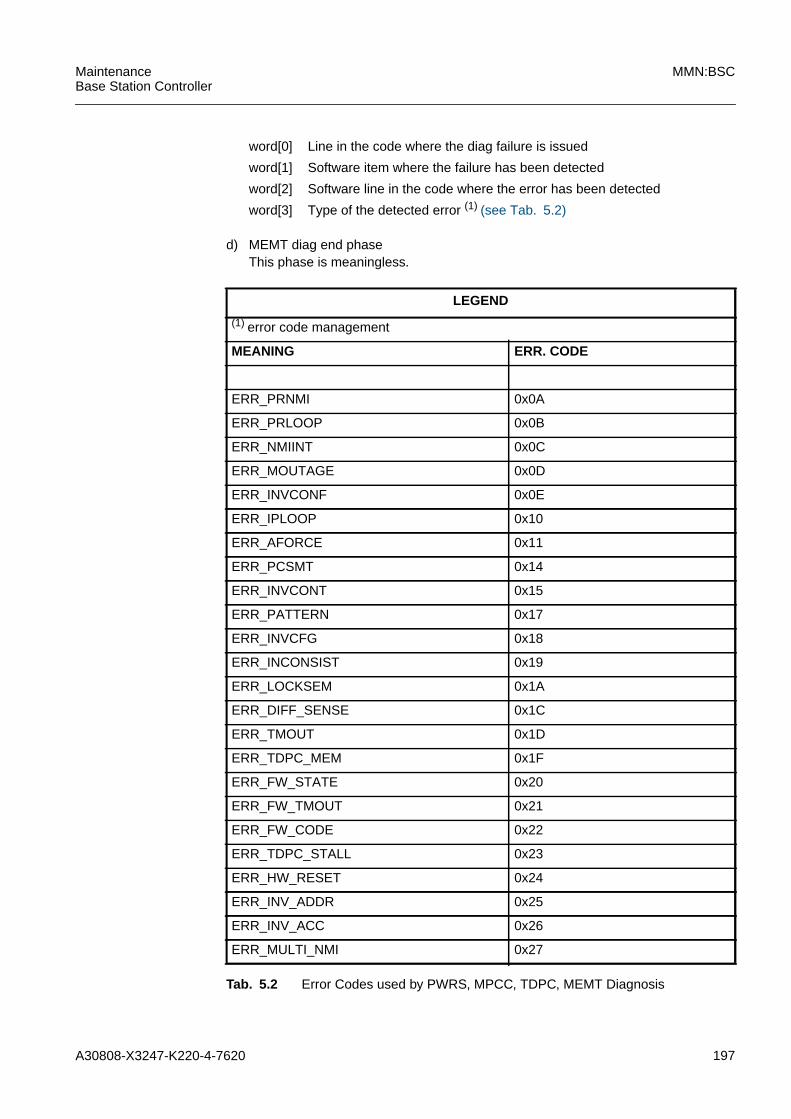
A30808-X3247-K220-4-7620 197
MaintenanceBase Station Controller
MMN:BSC
d) MEMT diag end phaseThis phase is meaningless.
word[0] Line in the code where the diag failure is issued
word[1] Software item where the failure has been detected
word[2] Software line in the code where the error has been detected
word[3] Type of the detected error (1) (see Tab. 5.2)
LEGEND
(1) error code management
MEANING ERR. CODE
ERR_PRNMI 0x0A
ERR_PRLOOP 0x0B
ERR_NMIINT 0x0C
ERR_MOUTAGE 0x0D
ERR_INVCONF 0x0E
ERR_IPLOOP 0x10
ERR_AFORCE 0x11
ERR_PCSMT 0x14
ERR_INVCONT 0x15
ERR_PATTERN 0x17
ERR_INVCFG 0x18
ERR_INCONSIST 0x19
ERR_LOCKSEM 0x1A
ERR_DIFF_SENSE 0x1C
ERR_TMOUT 0x1D
ERR_TDPC_MEM 0x1F
ERR_FW_STATE 0x20
ERR_FW_TMOUT 0x21
ERR_FW_CODE 0x22
ERR_TDPC_STALL 0x23
ERR_HW_RESET 0x24
ERR_INV_ADDR 0x25
ERR_INV_ACC 0x26
ERR_MULTI_NMI 0x27
Tab. 5.2 Error Codes used by PWRS, MPCC, TDPC, MEMT Diagnosis
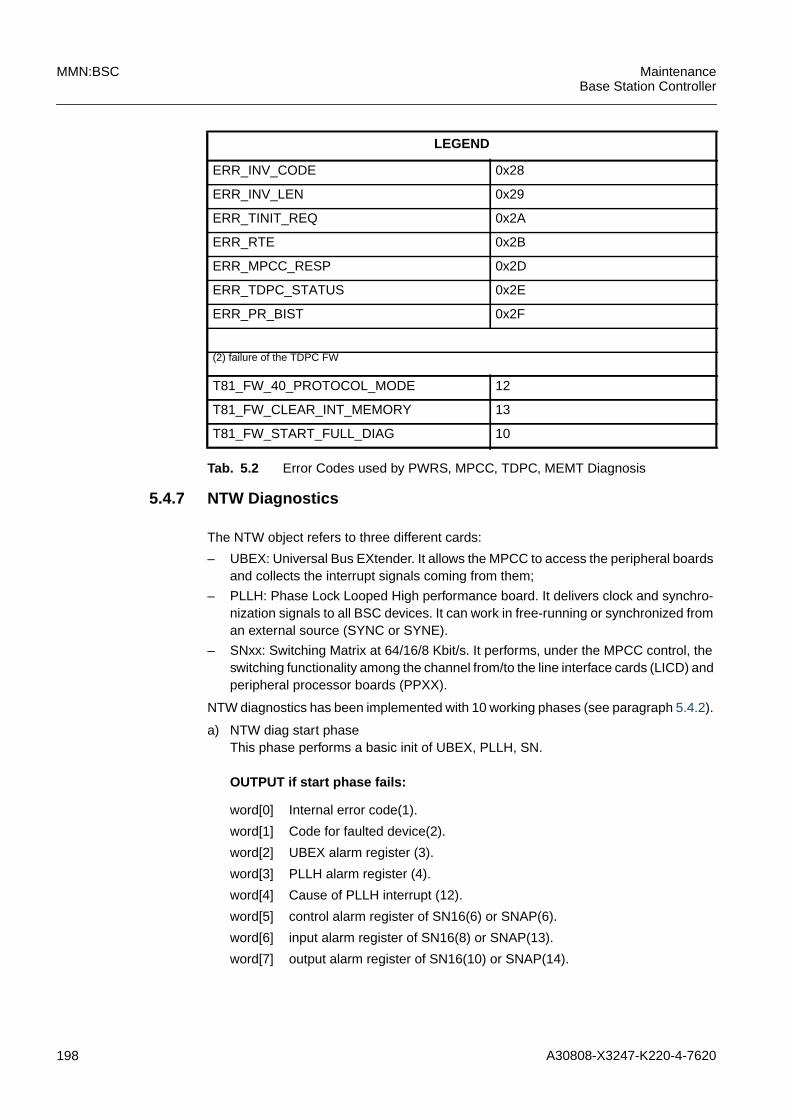
198 A30808-X3247-K220-4-7620
MMN:BSC MaintenanceBase Station Controller
5.4.7 NTW Diagnostics
The NTW object refers to three different cards:
– UBEX: Universal Bus EXtender. It allows the MPCC to access the peripheral boardsand collects the interrupt signals coming from them;
– PLLH: Phase Lock Looped High performance board. It delivers clock and synchro-nization signals to all BSC devices. It can work in free-running or synchronized froman external source (SYNC or SYNE).
– SNxx: Switching Matrix at 64/16/8 Kbit/s. It performs, under the MPCC control, theswitching functionality among the channel from/to the line interface cards (LICD) andperipheral processor boards (PPXX).
NTW diagnostics has been implemented with 10 working phases (see paragraph 5.4.2).
a) NTW diag start phaseThis phase performs a basic init of UBEX, PLLH, SN.
OUTPUT if start phase fails:
ERR_INV_CODE 0x28
ERR_INV_LEN 0x29
ERR_TINIT_REQ 0x2A
ERR_RTE 0x2B
ERR_MPCC_RESP 0x2D
ERR_TDPC_STATUS 0x2E
ERR_PR_BIST 0x2F
(2) failure of the TDPC FW
T81_FW_40_PROTOCOL_MODE 12
T81_FW_CLEAR_INT_MEMORY 13
T81_FW_START_FULL_DIAG 10
LEGEND
Tab. 5.2 Error Codes used by PWRS, MPCC, TDPC, MEMT Diagnosis
word[0] Internal error code(1).
word[1] Code for faulted device(2).
word[2] UBEX alarm register (3).
word[3] PLLH alarm register (4).
word[4] Cause of PLLH interrupt (12).
word[5] control alarm register of SN16(6) or SNAP(6).
word[6] input alarm register of SN16(8) or SNAP(13).
word[7] output alarm register of SN16(10) or SNAP(14).
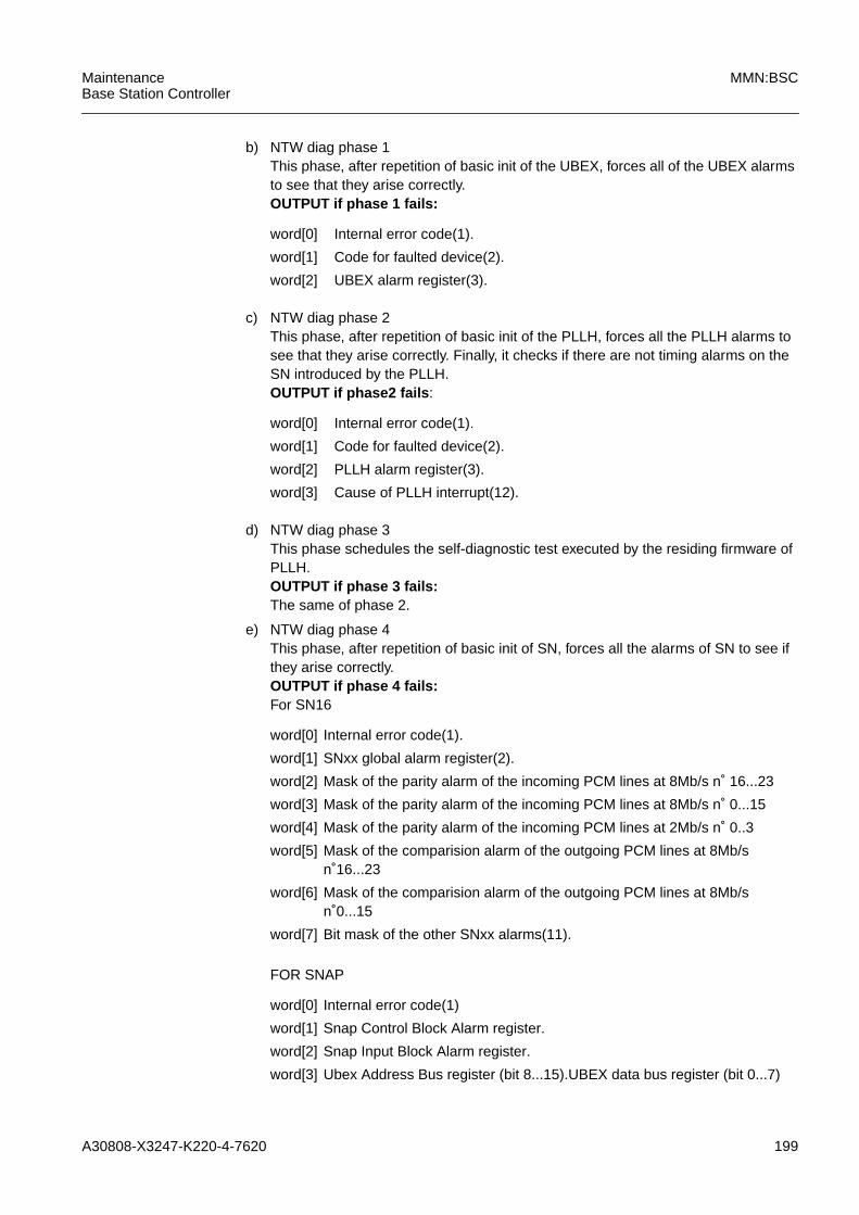
A30808-X3247-K220-4-7620 199
MaintenanceBase Station Controller
MMN:BSC
b) NTW diag phase 1This phase, after repetition of basic init of the UBEX, forces all of the UBEX alarmsto see that they arise correctly.OUTPUT if phase 1 fails:
c) NTW diag phase 2This phase, after repetition of basic init of the PLLH, forces all the PLLH alarms tosee that they arise correctly. Finally, it checks if there are not timing alarms on theSN introduced by the PLLH.OUTPUT if phase2 fails :
d) NTW diag phase 3This phase schedules the self-diagnostic test executed by the residing firmware ofPLLH.OUTPUT if phase 3 fails:The same of phase 2.
e) NTW diag phase 4This phase, after repetition of basic init of SN, forces all the alarms of SN to see ifthey arise correctly.OUTPUT if phase 4 fails:For SN16
FOR SNAP
word[0] Internal error code(1).
word[1] Code for faulted device(2).
word[2] UBEX alarm register(3).
word[0] Internal error code(1).
word[1] Code for faulted device(2).
word[2] PLLH alarm register(3).
word[3] Cause of PLLH interrupt(12).
word[0] Internal error code(1).
word[1] SNxx global alarm register(2).
word[2] Mask of the parity alarm of the incoming PCM lines at 8Mb/s n˚ 16...23
word[3] Mask of the parity alarm of the incoming PCM lines at 8Mb/s n˚ 0...15
word[4] Mask of the parity alarm of the incoming PCM lines at 2Mb/s n˚ 0..3
word[5] Mask of the comparision alarm of the outgoing PCM lines at 8Mb/sn˚16...23
word[6] Mask of the comparision alarm of the outgoing PCM lines at 8Mb/sn˚0...15
word[7] Bit mask of the other SNxx alarms(11).
word[0] Internal error code(1)
word[1] Snap Control Block Alarm register.
word[2] Snap Input Block Alarm register.
word[3] Ubex Address Bus register (bit 8...15).UBEX data bus register (bit 0...7)
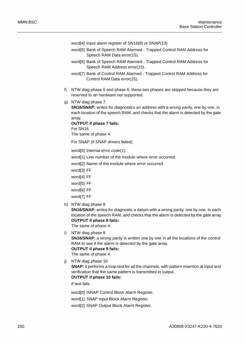
200 A30808-X3247-K220-4-7620
MMN:BSC MaintenanceBase Station Controller
f) NTW diag phase 5 and phase 6: these two phases are skipped because they arereserved to an hardware not supported.
g) NTW diag phase 7SN16/SNAP: writes for diagnostics an address with a wrong parity, one by one, ineach location of the speech RAM, and checks that the alarm is detected by the gatearray.OUTPUT if phase 7 fails:For SN16The same of phase 4.
For SNAP (if SNAP drivers failed).
h) NTW diag phase 8SN16/SNAP: writes for diagnostic a datum with a wrong parity, one by one, in eachlocation of the speech RAM, and checks that the alarm is detected by the gate array.OUTPUT if phase 8 fails:The same of phase 4.
i) NTW diag phase 9SN16/SNAP: a wrong parity is written one by one in all the locations of the controlRAM to see if the alarm is detected by the gate array.OUTPUT if phase 9 fails:The same of phase 4.
j) NTW diag phase 10SNAP: it performs a loop-test for all the channels, with pattern insertion at input andverification that the same pattern is transmitted in output.OUTPUT if phase 10 fails:
If test fails
word[4] Input alarm register of SN16(8) or SNAP(13)
word[5] Bank of Speech RAM Alarmed - Trapped Control RAM Address forSpeech RAM Data error(15).
word[6] Bank of Speech RAM Alarmed - Trapped Control RAM Address forSpeech RAM Address error(15).
word[7] Bank of Control RAM Alarmed - Trapped Control RAM Address forControl RAM Data error(15).
word[0] Internal error code(1).
word[1] Line number of the module where error occurred.
word[2] Name of the module where error occurred.
word[3] FF
word[4] FF
word[5] FF
word[6] FF
word[7] FF
word[0] iSNAP Control Block Alarm Register.
word[1] SNAP Input Block Alarm Register.
word[2] SNAP Output Block Alarm Register.

A30808-X3247-K220-4-7620 201
MaintenanceBase Station Controller
MMN:BSC
If Snap drivers fails
k) NTW diag end phaseThis phase is meaningless.
word[3] Trapped value on 8Mb/s input line, before pattern insertion-Patterninserted on 8 Mb/s input line-Trapped value on 8 Mb/s output line.
word[4] Number of physical input line.
word[5] Number of time slot at 8 Kb/s on physical input line.
word[6] Number of physical output line.
word[7] Number of time slot at 8 Kb/s on physical output line.
word[0] Internal error code(1).
word[1] Line number of the module where error occurred.
word[2] Name of the module where error occurred.
word[3] FF
word[4] FF
word[5] FF
word[6] FF
word[7] FF
LEGEND
(1) The possible error codes issued by NTW diagnostic are listed
ERR. CODE MEANING
1 loop back test failed
2 parity error on UBEX bus
3 an unexpected alarm is found active
5 forcing an alarm has no effect
6 (only PLLH) CRC error in the firmware protocol
7 (only PLLH) state inconsistency of the firmwareprotocol
8 time out occurred in the hardware/firmware oper-ation
17 the hardware has been found in unexpected state(typical for PLLH: it is found master whenexpected slave)
18 a connection in SNxx has been performed incor-rectly by the hardware
Tab. 5.3 Error Codes used by NTW Diagnostics
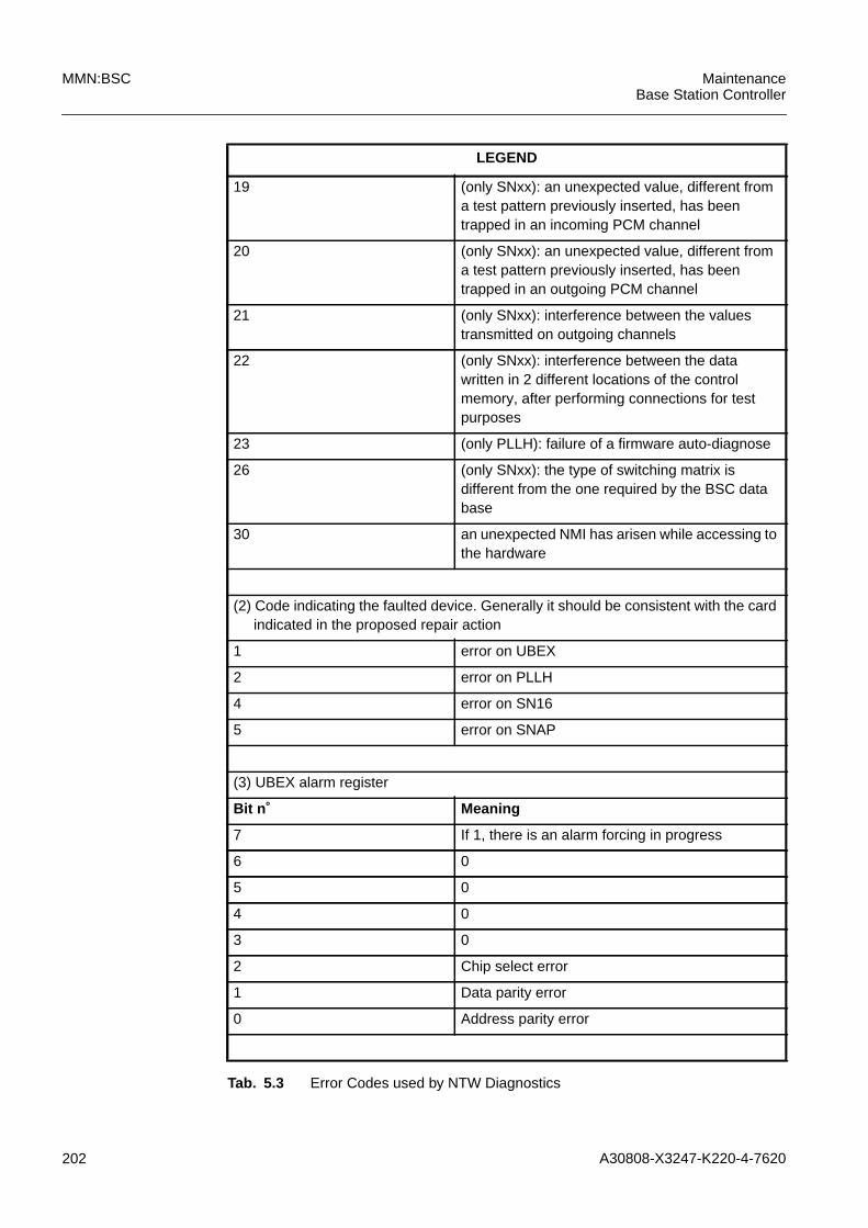
202 A30808-X3247-K220-4-7620
MMN:BSC MaintenanceBase Station Controller
19 (only SNxx): an unexpected value, different froma test pattern previously inserted, has beentrapped in an incoming PCM channel
20 (only SNxx): an unexpected value, different froma test pattern previously inserted, has beentrapped in an outgoing PCM channel
21 (only SNxx): interference between the valuestransmitted on outgoing channels
22 (only SNxx): interference between the datawritten in 2 different locations of the controlmemory, after performing connections for testpurposes
23 (only PLLH): failure of a firmware auto-diagnose
26 (only SNxx): the type of switching matrix isdifferent from the one required by the BSC database
30 an unexpected NMI has arisen while accessing tothe hardware
(2) Code indicating the faulted device. Generally it should be consistent with the cardindicated in the proposed repair action
1 error on UBEX
2 error on PLLH
4 error on SN16
5 error on SNAP
(3) UBEX alarm register
Bit n˚ Meaning
7 If 1, there is an alarm forcing in progress
6 0
5 0
4 0
3 0
2 Chip select error
1 Data parity error
0 Address parity error
LEGEND
Tab. 5.3 Error Codes used by NTW Diagnostics
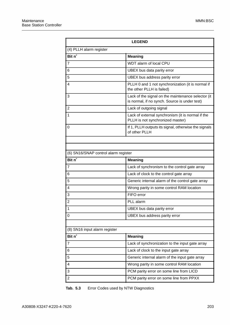
A30808-X3247-K220-4-7620 203
MaintenanceBase Station Controller
MMN:BSC
(4) PLLH alarm register
Bit n˚ Meaning
7 WDT alarm of local CPU
6 UBEX bus data parity error
5 UBEX bus address parity error
4 PLLH 0 and 1 not synchronization (it is normal ifthe other PLLH is failed)
3 Lack of the signal on the maintenance selector (itis normal, if no synch. Source is under test)
2 Lack of outgoing signal
1 Lack of external synchronism (it is normal if thePLLH is not synchronized master)
0 If 1, PLLH outputs its signal, otherwise the signalsof other PLLH
(6) SN16/SNAP control alarm register
Bit n˚ Meaning
7 Lack of synchronism to the control gate array
6 Lack of clock to the control gate array
5 Generic internal alarm of the control gate array
4 Wrong parity in some control RAM location
3 FIFO error
2 PLL alarm
1 UBEX bus data parity error
0 UBEX bus address parity error
(8) SN16 input alarm register
Bit n˚ Meaning
7 Lack of synchronization to the input gate array
6 Lack of clock to the input gate array
5 Generic internal alarm of the input gate array
4 Wrong parity in some control RAM location
3 PCM parity error on some line from LICD
2 PCM parity error on some line from PPXX
LEGEND
Tab. 5.3 Error Codes used by NTW Diagnostics
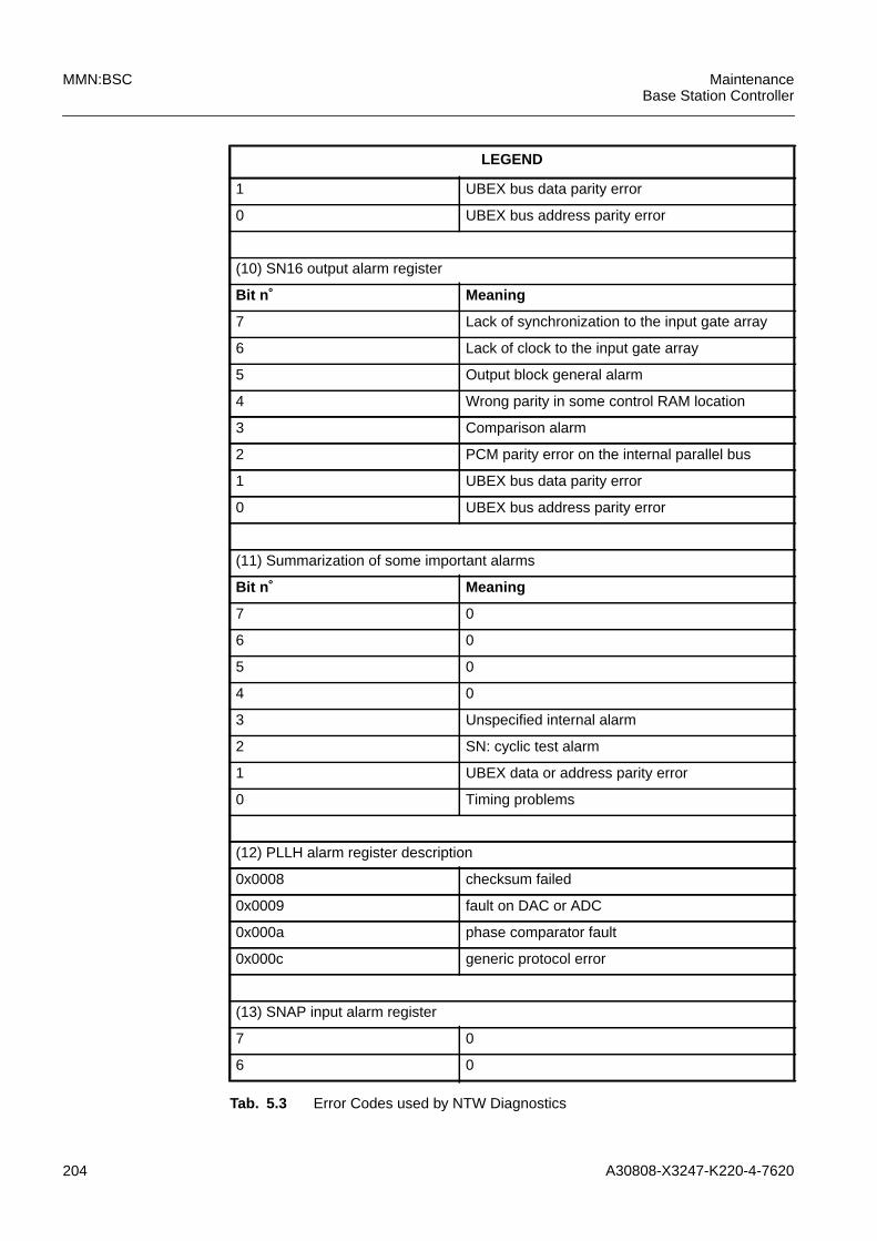
204 A30808-X3247-K220-4-7620
MMN:BSC MaintenanceBase Station Controller
1 UBEX bus data parity error
0 UBEX bus address parity error
(10) SN16 output alarm register
Bit n˚ Meaning
7 Lack of synchronization to the input gate array
6 Lack of clock to the input gate array
5 Output block general alarm
4 Wrong parity in some control RAM location
3 Comparison alarm
2 PCM parity error on the internal parallel bus
1 UBEX bus data parity error
0 UBEX bus address parity error
(11) Summarization of some important alarms
Bit n˚ Meaning
7 0
6 0
5 0
4 0
3 Unspecified internal alarm
2 SN: cyclic test alarm
1 UBEX data or address parity error
0 Timing problems
(12) PLLH alarm register description
0x0008 checksum failed
0x0009 fault on DAC or ADC
0x000a phase comparator fault
0x000c generic protocol error
(13) SNAP input alarm register
7 0
6 0
LEGEND
Tab. 5.3 Error Codes used by NTW Diagnostics
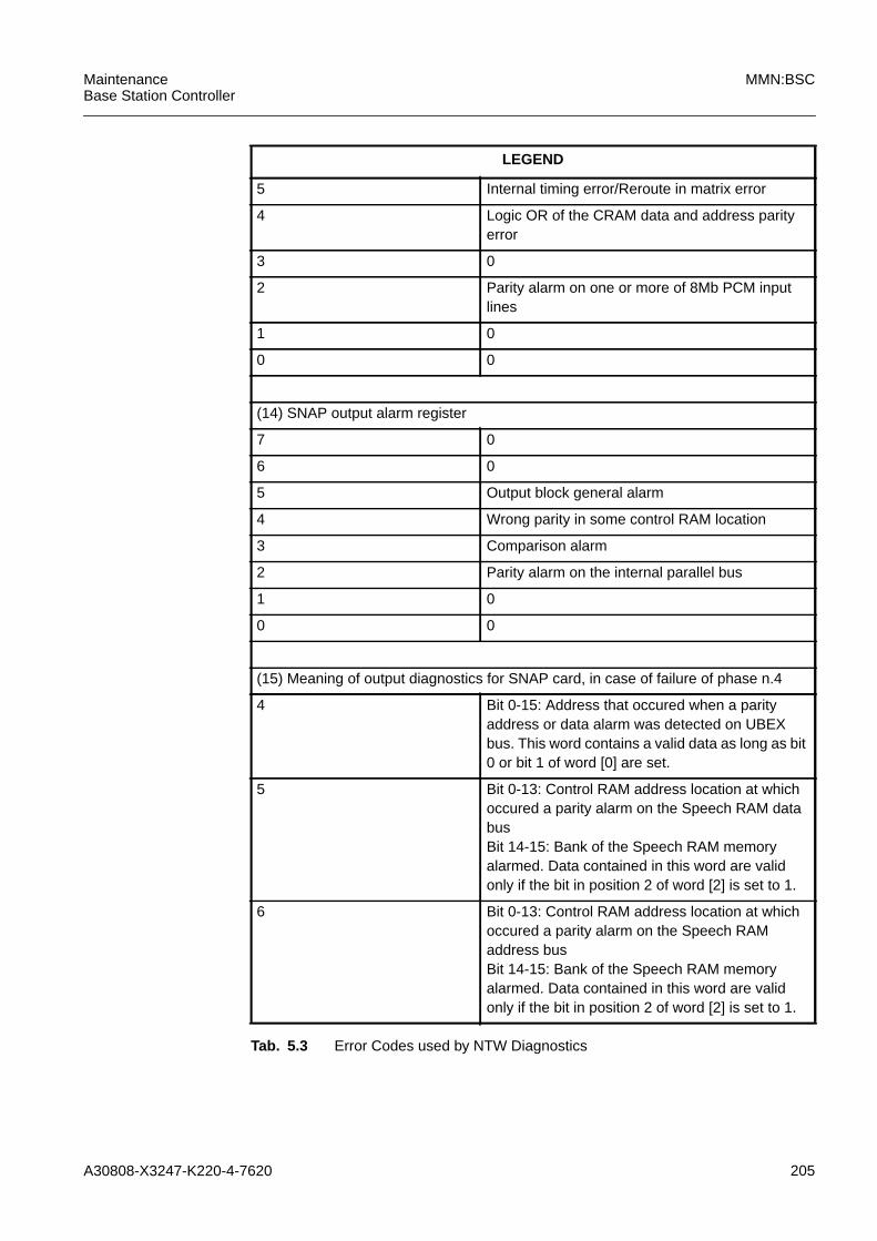
A30808-X3247-K220-4-7620 205
MaintenanceBase Station Controller
MMN:BSC
5 Internal timing error/Reroute in matrix error
4 Logic OR of the CRAM data and address parityerror
3 0
2 Parity alarm on one or more of 8Mb PCM inputlines
1 0
0 0
(14) SNAP output alarm register
7 0
6 0
5 Output block general alarm
4 Wrong parity in some control RAM location
3 Comparison alarm
2 Parity alarm on the internal parallel bus
1 0
0 0
(15) Meaning of output diagnostics for SNAP card, in case of failure of phase n.4
4 Bit 0-15: Address that occured when a parityaddress or data alarm was detected on UBEXbus. This word contains a valid data as long as bit0 or bit 1 of word [0] are set.
5 Bit 0-13: Control RAM address location at whichoccured a parity alarm on the Speech RAM databusBit 14-15: Bank of the Speech RAM memoryalarmed. Data contained in this word are validonly if the bit in position 2 of word [2] is set to 1.
6 Bit 0-13: Control RAM address location at whichoccured a parity alarm on the Speech RAMaddress busBit 14-15: Bank of the Speech RAM memoryalarmed. Data contained in this word are validonly if the bit in position 2 of word [2] is set to 1.
LEGEND
Tab. 5.3 Error Codes used by NTW Diagnostics

206 A30808-X3247-K220-4-7620
MMN:BSC MaintenanceBase Station Controller
5.4.8 PPLD/PPCC Diagnostics
The PPLD is responsible for handling the layer 2 of LAPD protocol. The card is basedon an INTEL CPU 80C186 running at 20 MHZ. The card architecture allows the down-load of the code.
The MPCC controls, for operating and maintenance purposes, the PPLD via the UBEX;the TDPC exchanges messages with the PPLD through a 8Mbyte dual port RAM; theselection of the active copy of the TDPC is under the control of the MPCC.
The LAPD circuit interfaces the switching matrix by means of a duplicated 2Mbit/s link;up to 8 physical channels can be interfaced both at 64kbit/s and 16kbit/s. An"n+m"redundancy concept is used for the cards that implement this function.
The PPCC board is responsible for handling the MTP layer 1 and 2 of the CommonChannel Signalling System #7 (CCSS#7) protocol used for signalling on the A interface.The hardware implementation of the PPCC is the same of the PPLD.
PPXX diagnostics has been implemented with 6 working phases (see paragraph 5.4.2).
a) PPXX diag start phaseThis phase checks on NTW outage and TDPC outage, loopback test, CPU reset,firmware autodiagnose, alarm-forcing test, software load.OUTPUT if start phase fails:
b) PPXX diag phase 1This phase executes memory tests (RAM, TDPC-PPXX DUAM, checksum verifica-tion of EPROM content).OUTPUT if phase 1 fails for hardware/firmware problems in diagnosticcommand execuion:
7 Bit 0-13: Control RAM address in case the outputgate array detects a data parity alarm on the databus of the control RAM itself.Data contained in this word are valid only if the bitin position 4 of word [2] is set to 1.
LEGEND
Tab. 5.3 Error Codes used by NTW Diagnostics
word[0] source item(1)
word[1] source code line
word[2] error code(2)
word[3] additional information(3)
word[4] additional information(4)
word[5] additional information(5)
word[6] additional information(6)
word[7] additional information(7).
word[0] error source item (1)
word[1] error line inside source code
word[2] error code (2)
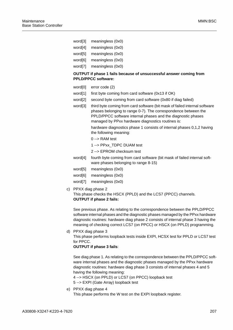
A30808-X3247-K220-4-7620 207
MaintenanceBase Station Controller
MMN:BSC
OUTPUT if phase 1 fails because of unsuccessful answer coming fromPPLD/PPCC software:
c) PPXX diag phase 2This phase checks the HSCX (PPLD) and the LCS7 (PPCC) channels.OUTPUT if phase 2 fails:
See previous phase. As relating to the correspondence between the PPLD/PPCCsoftware internal phases and the diagnostic phases managed by the PPxx hardwarediagnostic routines: hardware diag phase 2 consists of internal phase 3 having themeaning of checking correct LCS7 (on PPCC) or HSCX (on PPLD) programming.
d) PPXX diag phase 3This phase performs loopback tests inside EXPI, HCSX test for PPLD or LCS7 testfor PPCC.OUTPUT if phase 3 fails :
See diag phase 1. As relating to the correspondence between the PPLD/PPCC soft-ware internal phases and the diagnostic phases managed by the PPxx hardwarediagnostic routines: hardware diag phase 3 consists of internal phases 4 and 5having the following meaning:4 --> HSCX (on PPLD) or LCS7 (on PPCC) loopback test5 --> EXPI (Gate Array) loopback test
e) PPXX diag phase 4This phase performs the W test on the EXPI loopback register.
word[3] meaningless (0x0)
word[4] meaningless (0x0)
word[5] meaningless (0x0)
word[6] meaningless (0x0)
word[7] meaningless (0x0)
word[0] error code (2)
word[1] first byte coming from card software (0x13 if OK)
word[2] second byte coming from card software (0x80 if diag failed)
word[3] third byte coming from card software (bit mask of failed internal softwarephases belonging to range 0-7). The correspondence between thePPLD/PPCC software internal phases and the diagnostic phasesmanaged by PPxx hardware diagnostics routines is:
hardware diagnostics phase 1 consists of internal phases 0,1,2 havingthe following meaning:
0 --> RAM test
1 --> PPxx_TDPC DUAM test
2 --> EPROM checksum test
word[4] fourth byte coming from card software (bit mask of failed internal soft-ware phases belonging to range 8-15)
word[5] meaningless (0x0)
word[6] meaningless (0x0)
word[7] meaningless (0x0)
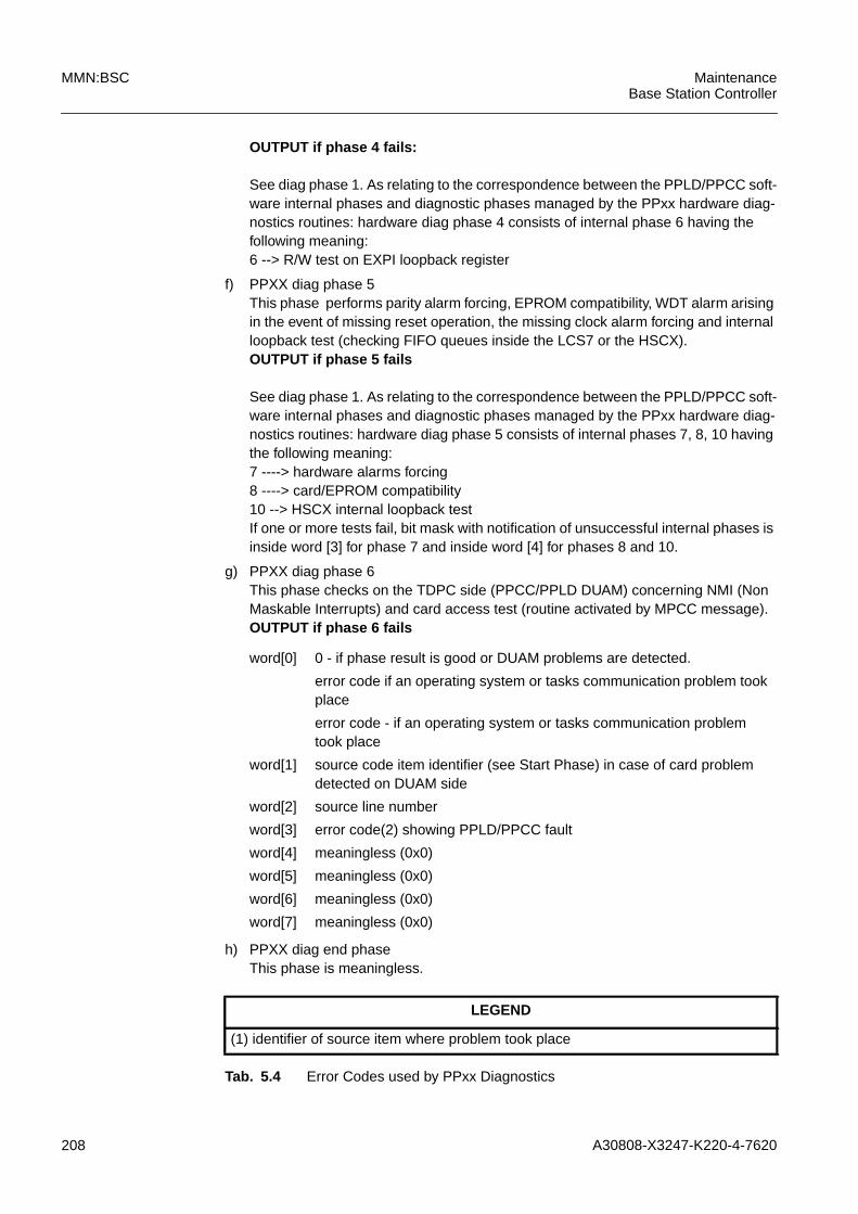
208 A30808-X3247-K220-4-7620
MMN:BSC MaintenanceBase Station Controller
OUTPUT if phase 4 fails:
See diag phase 1. As relating to the correspondence between the PPLD/PPCC soft-ware internal phases and diagnostic phases managed by the PPxx hardware diag-nostics routines: hardware diag phase 4 consists of internal phase 6 having thefollowing meaning:6 --> R/W test on EXPI loopback register
f) PPXX diag phase 5This phase performs parity alarm forcing, EPROM compatibility, WDT alarm arisingin the event of missing reset operation, the missing clock alarm forcing and internalloopback test (checking FIFO queues inside the LCS7 or the HSCX).OUTPUT if phase 5 fails
See diag phase 1. As relating to the correspondence between the PPLD/PPCC soft-ware internal phases and diagnostic phases managed by the PPxx hardware diag-nostics routines: hardware diag phase 5 consists of internal phases 7, 8, 10 havingthe following meaning:7 ----> hardware alarms forcing8 ----> card/EPROM compatibility10 --> HSCX internal loopback testIf one or more tests fail, bit mask with notification of unsuccessful internal phases isinside word [3] for phase 7 and inside word [4] for phases 8 and 10.
g) PPXX diag phase 6This phase checks on the TDPC side (PPCC/PPLD DUAM) concerning NMI (NonMaskable Interrupts) and card access test (routine activated by MPCC message).OUTPUT if phase 6 fails
h) PPXX diag end phaseThis phase is meaningless.
word[0] 0 - if phase result is good or DUAM problems are detected.
error code if an operating system or tasks communication problem tookplace
error code - if an operating system or tasks communication problemtook place
word[1] source code item identifier (see Start Phase) in case of card problemdetected on DUAM side
word[2] source line number
word[3] error code(2) showing PPLD/PPCC fault
word[4] meaningless (0x0)
word[5] meaningless (0x0)
word[6] meaningless (0x0)
word[7] meaningless (0x0)
LEGEND
(1) identifier of source item where problem took place
Tab. 5.4 Error Codes used by PPxx Diagnostics

A30808-X3247-K220-4-7620 209
MaintenanceBase Station Controller
MMN:BSC
1 DHXXDCCH
2 DHXXDCDE
3 DHXXDCEH
4 DHXXDCSA
5 DHXXDCSM
6 DHXXDCTH
7 DHXXDDDI
8 DHXXDDHD
9 DHXXGSUT
10 DHXXININ
11 DGHDXXDP
(2) error code description
NTW_outage_test 0001h
TDPC_outage_test 0002h
loop_test 00e3h (access to loopback reg.)
00e4h (NMI)
FW_diagnose_test 00e2h (firmware self test failed)
008ah (firmware time out)
alarm_test 00a1h (forcing failed)
00a0h (alarm persists)
SW_load_test 000ch (load failed)
0014h (file system problem)
operating system problems 000ah (mailbox creation failed, null DH answer)
tasks interface problems 000bh (PPxx DH-time-out during load function)
software start 0080h (sw nack answer) or 008ah (sw time out)
forcing Out Of Service Idle status 008ch (software nack answer) or 008ah (sw timeout)
alarm raising during card access 008ch (time-out expired in command sending)
00a0h (alarm detected during reading operationof software answer)
LEGEND
Tab. 5.4 Error Codes used by PPxx Diagnostics

210 A30808-X3247-K220-4-7620
MMN:BSC MaintenanceBase Station Controller
problems during command tocard
00a3h (writing error on MPCC-PPXX interface)0082h (negative software answer, different fromDiag Executed)0090h (Diag Failed answer inside softwaresecond byte)
loopback test 00e4h if NMI problem00e3h if card access problem
(3) additional information; in details:
NTW/TDPC outage, operatingsystem problem, software time-out, firmware diagnosis failure,software start/Force
If card access for report is successful:high byte=parity alarm cause (if any)low byte=mask of alarms not causing interrupts
OOS failure, load failure If card access for report fails: source code item(1)
other causes mask of alarms causing interrupts (high byte);mask of alarms not causing interrupts (low byte)
(4) additional information; in details:
NTW/TDPC outage, operatingsystem problem, software time-out, firmware diagnosis failure,software start/Force OOS failure,load failure
If card access for report is successful:high byte = mask of alarms causing interruptslow byte = circuits enabled to transmit (to NTW) ifcard access (for report) fails: source line number
other causes trapped PCM channel address (parity error) (highbyte); control mask of alarms towards UBEX (lowbyte)
(5) additional information; in details:
NTW/TDPC outage, operatingsystem problem, software time-out, firmware diagnosis failure,software start/Force OOS failure,load failure
If card access for report is successful:high byte = first card control registerlow byte = second card control register. If cardaccess (for report) fails: error code (2)
other causes trapped PCM channel data
(6) additional information; in details:
LEGEND
Tab. 5.4 Error Codes used by PPxx Diagnostics
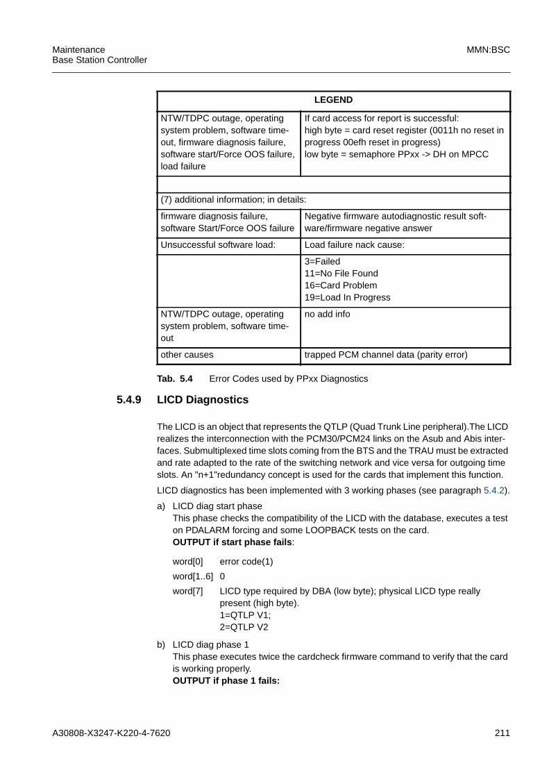
A30808-X3247-K220-4-7620 211
MaintenanceBase Station Controller
MMN:BSC
5.4.9 LICD Diagnostics
The LICD is an object that represents the QTLP (Quad Trunk Line peripheral).The LICDrealizes the interconnection with the PCM30/PCM24 links on the Asub and Abis inter-faces. Submultiplexed time slots coming from the BTS and the TRAU must be extractedand rate adapted to the rate of the switching network and vice versa for outgoing timeslots. An "n+1"redundancy concept is used for the cards that implement this function.
LICD diagnostics has been implemented with 3 working phases (see paragraph 5.4.2).
a) LICD diag start phaseThis phase checks the compatibility of the LICD with the database, executes a teston PDALARM forcing and some LOOPBACK tests on the card.OUTPUT if start phase fails :
b) LICD diag phase 1This phase executes twice the cardcheck firmware command to verify that the cardis working properly.OUTPUT if phase 1 fails:
NTW/TDPC outage, operatingsystem problem, software time-out, firmware diagnosis failure,software start/Force OOS failure,load failure
If card access for report is successful:high byte = card reset register (0011h no reset inprogress 00efh reset in progress)low byte = semaphore PPxx -> DH on MPCC
(7) additional information; in details:
firmware diagnosis failure,software Start/Force OOS failure
Negative firmware autodiagnostic result soft-ware/firmware negative answer
Unsuccessful software load: Load failure nack cause:
3=Failed11=No File Found16=Card Problem19=Load In Progress
NTW/TDPC outage, operatingsystem problem, software time-out
no add info
other causes trapped PCM channel data (parity error)
LEGEND
Tab. 5.4 Error Codes used by PPxx Diagnostics
word[0] error code(1)
word[1..6] 0
word[7] LICD type required by DBA (low byte); physical LICD type reallypresent (high byte).1=QTLP V1;2=QTLP V2

212 A30808-X3247-K220-4-7620
MMN:BSC MaintenanceBase Station Controller
The same as start phase.
c) LICD diag phase 2This phase performs the card reset, test network copy programming and executesdiagnostic checks on the specified card.OUTPUT if phase 2 fails:
d) LICD diag phase 3This phase performs card reset, test network copy programming and executes diag-nostic check on specified card.OUTPUT if phase 3 fails:
e) LICD diag end phaseThis phase is meaningless.OUTPUT if end phase fails:
word[0] error code(1)
word[1] firmware diagnose report(2)
word[2] firmware diagnose report(2)
word[3] firmware diagnose report(2)
word[4..6] 0
word[7] LICD type required by DBA (low byte);physical LICD type actually present(high byte).1=QTLP V1;2=QTLP V2
word[0] = error code(1); word[1-6] = 0 if card access fails OR
word[0-3]=; word[4-6] = 0 OR
word[7] = as word[7] of phase SP, WP
word[0] error code(1) ALARM REPORT(3)
word[1..6] 0 ALARM REPORT(3)
word[7] 0 ALARM REPORT(3)
word[0] = error code(1) if access card fails; word[1-7] = 0 OR
word[0-7]= ALARM REPORT(3)
The same as start phase.
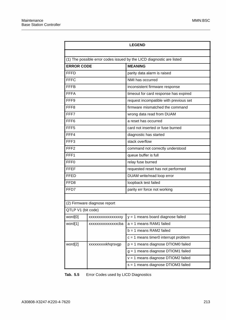
A30808-X3247-K220-4-7620 213
MaintenanceBase Station Controller
MMN:BSC
LEGEND
(1) The possible error codes issued by the LICD diagnostic are listed
ERROR CODE MEANING
FFFD parity data alarm is raised
FFFC NMI has occurred
FFFB inconsistent firmware response
FFFA timeout for card response has expired
FFF9 request incompatible with previous set
FFF8 firmware mismatched the command
FFF7 wrong data read from DUAM
FFF6 a reset has occurred
FFF5 card not inserted or fuse burned
FFF4 diagnostic has started
FFF3 stack overflow
FFF2 command not correctly understood
FFF1 queue buffer is full
FFF0 relay fuse burned
FFEF requested reset has not performed
FFED DUAM write/read loop error
FFD8 loopback test failed
FFD7 parity err force not working
(2) Firmware diagnose report
QTLP V1 (bit code)
word[0] xxxxxxxxxxxxxxxxxy y = 1 means board diagnose failed
word[1] xxxxxxxxxxxxxxxcba a = 1 means RAM1 failed
b = 1 means RAM2 failed
c = 1 means timer0 interrupt problem
word[2] xxxxxxxxxkhqrsvgp p = 1 means diagnose DTIOM0 failed
g = 1 means diagnose DTIOM1 failed
v = 1 means diagnose DTIOM2 failed
s = 1 means diagnose DTIOM3 failed
Tab. 5.5 Error Codes used by LICD Diagnostics
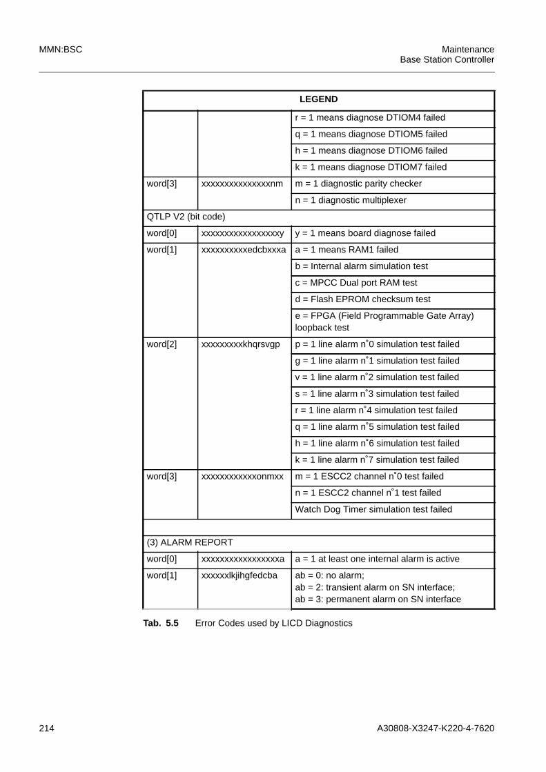
214 A30808-X3247-K220-4-7620
MMN:BSC MaintenanceBase Station Controller
r = 1 means diagnose DTIOM4 failed
q = 1 means diagnose DTIOM5 failed
h = 1 means diagnose DTIOM6 failed
k = 1 means diagnose DTIOM7 failed
word[3] xxxxxxxxxxxxxxxnm m = 1 diagnostic parity checker
n = 1 diagnostic multiplexer
QTLP V2 (bit code)
word[0] xxxxxxxxxxxxxxxxxy y = 1 means board diagnose failed
word[1] xxxxxxxxxxedcbxxxa a = 1 means RAM1 failed
b = Internal alarm simulation test
c = MPCC Dual port RAM test
d = Flash EPROM checksum test
e = FPGA (Field Programmable Gate Array)loopback test
word[2] xxxxxxxxxkhqrsvgp p = 1 line alarm n˚0 simulation test failed
g = 1 line alarm n˚1 simulation test failed
v = 1 line alarm n˚2 simulation test failed
s = 1 line alarm n˚3 simulation test failed
r = 1 line alarm n˚4 simulation test failed
q = 1 line alarm n˚5 simulation test failed
h = 1 line alarm n˚6 simulation test failed
k = 1 line alarm n˚7 simulation test failed
word[3] xxxxxxxxxxxxonmxx m = 1 ESCC2 channel n˚0 test failed
n = 1 ESCC2 channel n˚1 test failed
Watch Dog Timer simulation test failed
(3) ALARM REPORT
word[0] xxxxxxxxxxxxxxxxxa a = 1 at least one internal alarm is active
word[1] xxxxxxlkjihgfedcba ab = 0: no alarm;ab = 2: transient alarm on SN interface;ab = 3: permanent alarm on SN interface
LEGEND
Tab. 5.5 Error Codes used by LICD Diagnostics
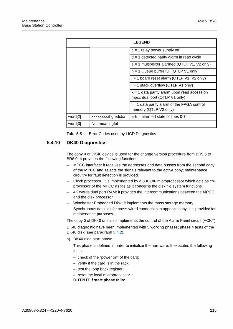
A30808-X3247-K220-4-7620 215
MaintenanceBase Station Controller
MMN:BSC
5.4.10 DK40 Diagnostics
The copy 0 of DK40 device is used for the change version procedure from BR5.5 toBR6.0. It provides the following functions:
– MPCC interface: it receives the addresses and data busses from the second copyof the MPCC and selects the signals relevant to the active copy; maintenancecircuitry for fault detection is provided.
– Clock processor: it is implemented by a 80C186 microprocessor which acts as co-processor of the MPCC as fas as it concerns the disk file system functions.
– 4K words dual port RAM: it provides the intercommunications between the MPCCand the disk processor.
– Winchester Embedded Disk: it implements the mass storage memory.
– Synchronous data link for cross-wired connection to opposite copy: it is provided formaintenance purposes.
The copy 0 of DK40 unit also implements the control of the Alarm Panel circuit (ACKT).
DK40 diagnostic have been implemented with 5 working phases; phase 4 tests of theDK40 disk (see paragraph 5.4.2).
a) DK40 diag start phase
This phase is defined in order to initialize the hardware. It executes the followingtests:
– check of the “power on” of the card;
– verify if the card is in the rack;
– test the loop back register;
– reset the local microprocessor.OUTPUT if start phase fails:
c = 1 relay power supply off
d = 1 detected parity alarm in read cycle
e = 1 multiplexer alarmed (QTLP V1, V2 only)
h = 1 Queue buffer full (QTLP V1 only)
i = 1 board reset alarm (QTLP V1, V2 only)
j = 1 stack overflow (QTLP V1 only)
k = 1 data parity alarm upon read access onmpcc dual port (QTLP V1 only)
l = 1 data parity alarm of the FPGA controlmemory (QTLP V2 only)
word[2] xxxxxxxxxhgfedcba a-h = alarmed state of lines 0-7
word[3] Not meaningful
LEGEND
Tab. 5.5 Error Codes used by LICD Diagnostics

216 A30808-X3247-K220-4-7620
MMN:BSC MaintenanceBase Station Controller
word[0] 0x0001 POWER_ON_TEST
word[1] 0x8004 card_not_powered
word[2] MPCC_sense_point_register
word[0] 0x0002 INSERTION_TEST
word[1] 0x8005 card_not_inserted
word[2] MPCC_sense_point_register
word[0] 0x0002 INSERTION_TEST
word[1] 0x8006 NMI_1st_access
word[0] 0x0003 ACCESS_DETECTOR_TEST
word[1] 0xf000 nmi_after_alarm_reset
word[0] 0x0003 ACCESS_DETECTOR_TEST
word[1] 0xf002 nmi_after_sem_lock
word[2] MPCC_sense_point_register
word[0] 0x0003 ACCESS_DETECTOR_TEST
word[1] 0xf003 sem_not_locked
word[2] maintenance_semaphore_lock_result+alarm_semaphore_lock_result
word[0] 0x0003 ACCESS_DETECTOR_TEST
word[1] 0x8007 nmi_wr_word1
word[2] MPCC_sense_point_register
word[0] 0x0003 ACCESS_DETECTOR_TEST
word[1] 0x8008 w1_comp_failed
word[2] value written to the PCS loopbackregister
word[0] 0x0003 ACCESS_DETECTOR_TEST
word[1] 0x8009 nmi_wr_word0
word[2] MPCC_sense_point_register
word[0] 0x0003 ACCESS_DETECTOR_TEST
word[1] 0x800a w0_comp_failed
word[2] value written to the PCS loopbackregister
word[0] 0x0003 ACCESS_DETECTOR_TEST
word[1] 0xf004 sem_not_released
word[2] nmi_after_micro_reset
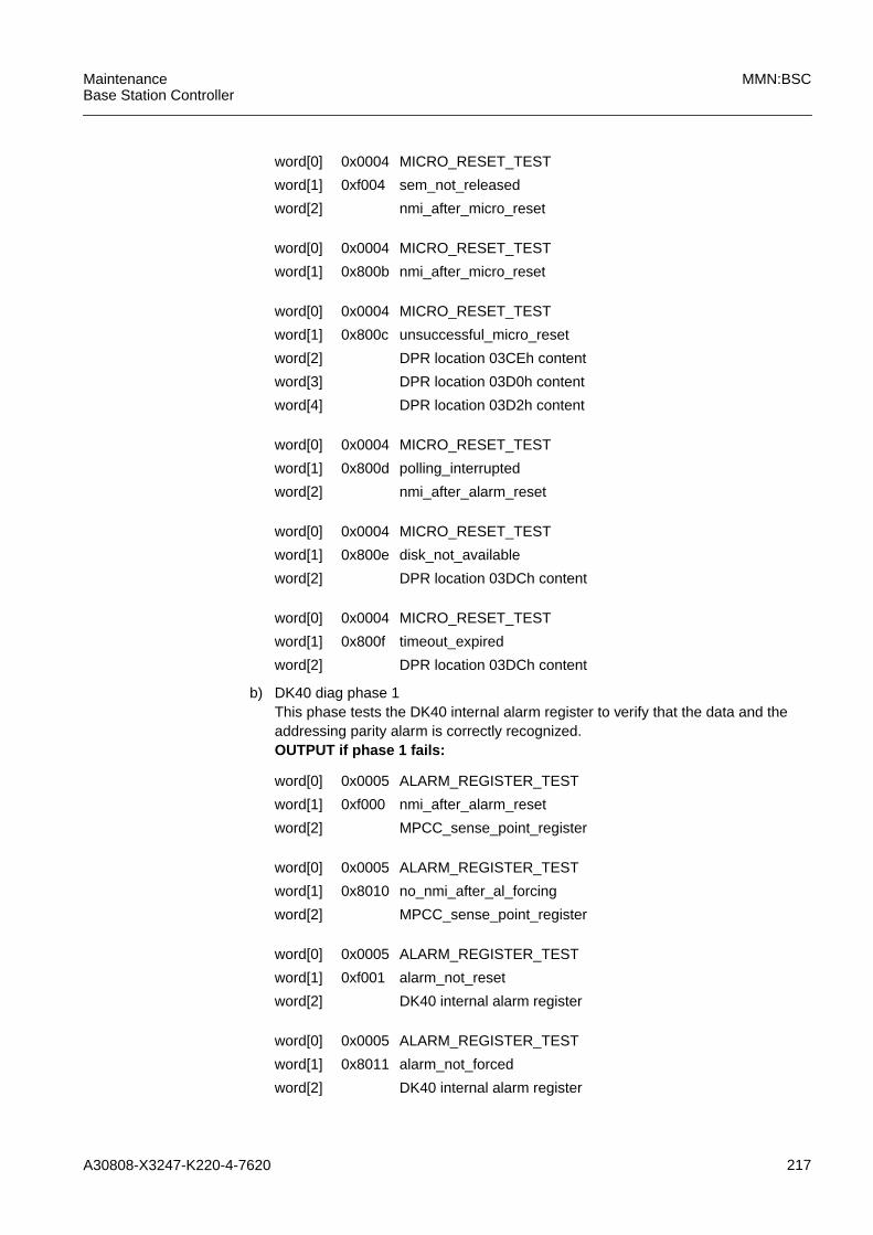
A30808-X3247-K220-4-7620 217
MaintenanceBase Station Controller
MMN:BSC
b) DK40 diag phase 1This phase tests the DK40 internal alarm register to verify that the data and theaddressing parity alarm is correctly recognized.OUTPUT if phase 1 fails:
word[0] 0x0004 MICRO_RESET_TEST
word[1] 0xf004 sem_not_released
word[2] nmi_after_micro_reset
word[0] 0x0004 MICRO_RESET_TEST
word[1] 0x800b nmi_after_micro_reset
word[0] 0x0004 MICRO_RESET_TEST
word[1] 0x800c unsuccessful_micro_reset
word[2] DPR location 03CEh content
word[3] DPR location 03D0h content
word[4] DPR location 03D2h content
word[0] 0x0004 MICRO_RESET_TEST
word[1] 0x800d polling_interrupted
word[2] nmi_after_alarm_reset
word[0] 0x0004 MICRO_RESET_TEST
word[1] 0x800e disk_not_available
word[2] DPR location 03DCh content
word[0] 0x0004 MICRO_RESET_TEST
word[1] 0x800f timeout_expired
word[2] DPR location 03DCh content
word[0] 0x0005 ALARM_REGISTER_TEST
word[1] 0xf000 nmi_after_alarm_reset
word[2] MPCC_sense_point_register
word[0] 0x0005 ALARM_REGISTER_TEST
word[1] 0x8010 no_nmi_after_al_forcing
word[2] MPCC_sense_point_register
word[0] 0x0005 ALARM_REGISTER_TEST
word[1] 0xf001 alarm_not_reset
word[2] DK40 internal alarm register
word[0] 0x0005 ALARM_REGISTER_TEST
word[1] 0x8011 alarm_not_forced
word[2] DK40 internal alarm register
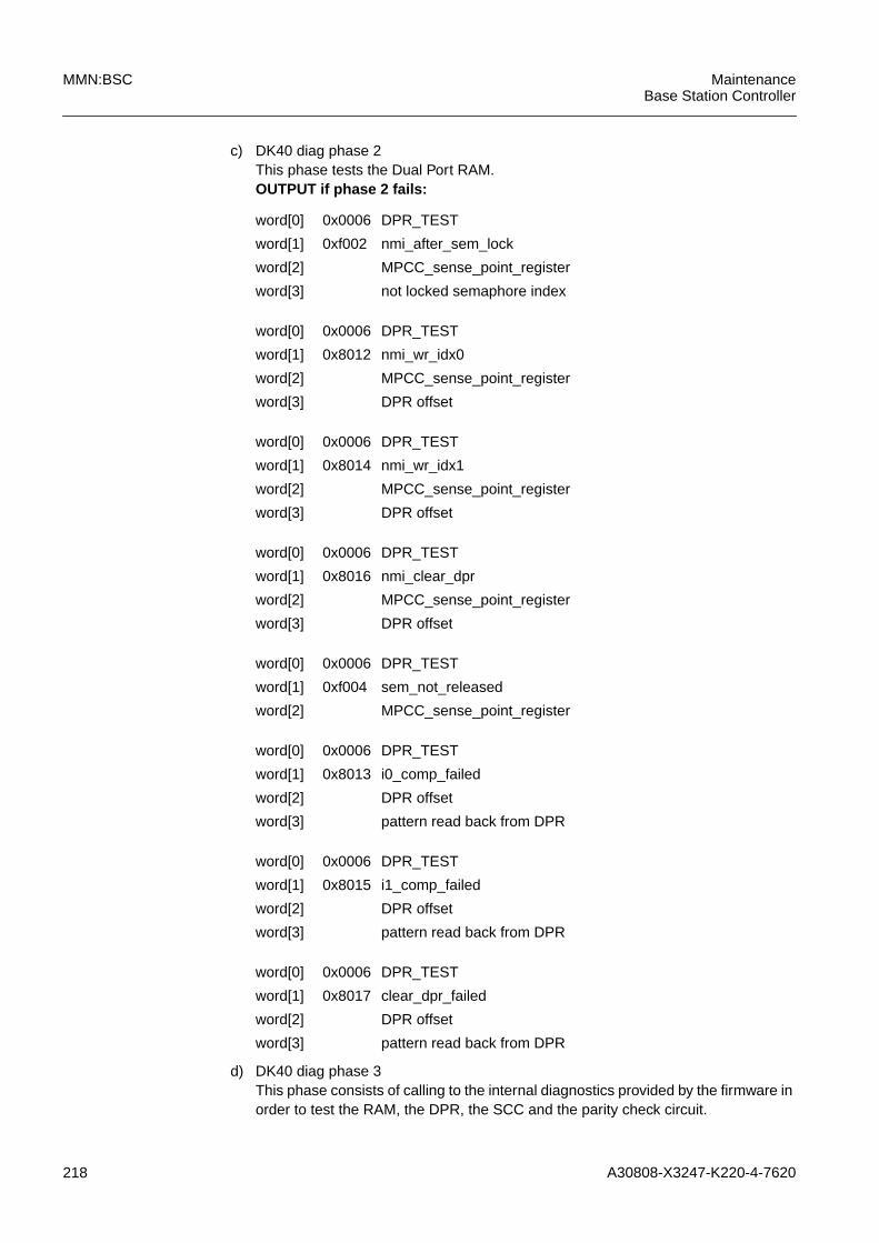
218 A30808-X3247-K220-4-7620
MMN:BSC MaintenanceBase Station Controller
c) DK40 diag phase 2This phase tests the Dual Port RAM.OUTPUT if phase 2 fails:
d) DK40 diag phase 3This phase consists of calling to the internal diagnostics provided by the firmware inorder to test the RAM, the DPR, the SCC and the parity check circuit.
word[0] 0x0006 DPR_TEST
word[1] 0xf002 nmi_after_sem_lock
word[2] MPCC_sense_point_register
word[3] not locked semaphore index
word[0] 0x0006 DPR_TEST
word[1] 0x8012 nmi_wr_idx0
word[2] MPCC_sense_point_register
word[3] DPR offset
word[0] 0x0006 DPR_TEST
word[1] 0x8014 nmi_wr_idx1
word[2] MPCC_sense_point_register
word[3] DPR offset
word[0] 0x0006 DPR_TEST
word[1] 0x8016 nmi_clear_dpr
word[2] MPCC_sense_point_register
word[3] DPR offset
word[0] 0x0006 DPR_TEST
word[1] 0xf004 sem_not_released
word[2] MPCC_sense_point_register
word[0] 0x0006 DPR_TEST
word[1] 0x8013 i0_comp_failed
word[2] DPR offset
word[3] pattern read back from DPR
word[0] 0x0006 DPR_TEST
word[1] 0x8015 i1_comp_failed
word[2] DPR offset
word[3] pattern read back from DPR
word[0] 0x0006 DPR_TEST
word[1] 0x8017 clear_dpr_failed
word[2] DPR offset
word[3] pattern read back from DPR

A30808-X3247-K220-4-7620 219
MaintenanceBase Station Controller
MMN:BSC
OUTPUT if phase 3 fails:
e) DK40 diag phase 4This phase consists of calling the internal diagnostics provided by the firmware inorder to test the hard disk.OUTPUT if phase 4 fails:
f) DK40 diag phase 5This phase is defined in order to diagnose the alarm panel interface: it consists oftesting the lamp numbered 8..23 and the lamp numbered 0..7 corresponding to therelay drivers.OUTPUT if phase 5 fails:
g) DK40 diag end phaseThis phase is meaningless in the DK40 diagnostics.
word[0] 0x0007 FW_TEST
word[1] xxxxxxxxxxxxxxxxxxdcba a = 1 means RAM fault
b = 2means DPR fault
c = 3means SCC fault
d = 4means parity check ckt fault
word[2] DK40 internal alarmregister
word[0] 0x0008 DISK_TEST
word[1] xxxxxxxxxxxxxxxxbxxxxa a = 1 means disk fault
b = 1 means disk not ready
word[2] DK40 internal alarmregister
word[0] 0x0009 ALARM_PANEL_TEST
word[1] 0x8018 lamps_not_turned_off
0x8019 set_lamp_failed
0x801a get_lamp_failed
word[2] DK40 internal alarm register
word[3] not working lamp state (high byte) + notworking lamp number
word[4] RELAY_DRIVERS_LAMP_TEST
word[5] 0x8018 lamps_not_turned_off
0x8019 set_lamp_failed
0x801a get_lamp_failed
word[6] DK40 internal alarm register
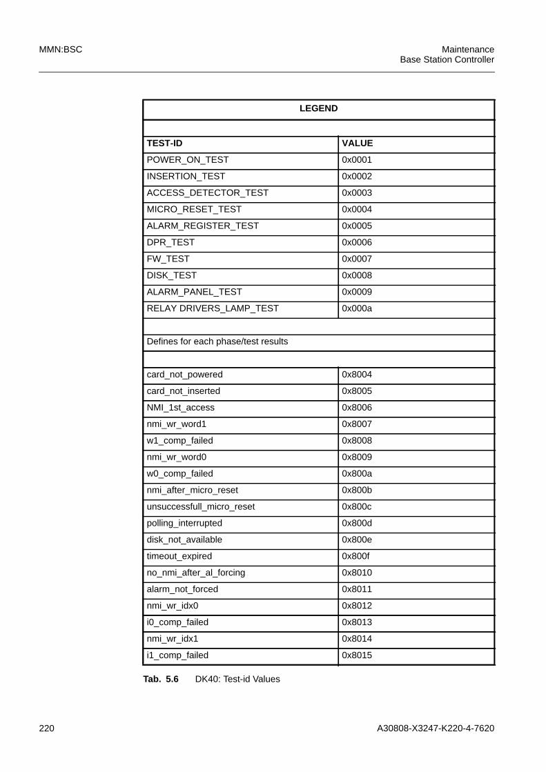
220 A30808-X3247-K220-4-7620
MMN:BSC MaintenanceBase Station Controller
LEGEND
TEST-ID VALUE
POWER_ON_TEST 0x0001
INSERTION_TEST 0x0002
ACCESS_DETECTOR_TEST 0x0003
MICRO_RESET_TEST 0x0004
ALARM_REGISTER_TEST 0x0005
DPR_TEST 0x0006
FW_TEST 0x0007
DISK_TEST 0x0008
ALARM_PANEL_TEST 0x0009
RELAY DRIVERS_LAMP_TEST 0x000a
Defines for each phase/test results
card_not_powered 0x8004
card_not_inserted 0x8005
NMI_1st_access 0x8006
nmi_wr_word1 0x8007
w1_comp_failed 0x8008
nmi_wr_word0 0x8009
w0_comp_failed 0x800a
nmi_after_micro_reset 0x800b
unsuccessfull_micro_reset 0x800c
polling_interrupted 0x800d
disk_not_available 0x800e
timeout_expired 0x800f
no_nmi_after_al_forcing 0x8010
alarm_not_forced 0x8011
nmi_wr_idx0 0x8012
i0_comp_failed 0x8013
nmi_wr_idx1 0x8014
i1_comp_failed 0x8015
Tab. 5.6 DK40: Test-id Values

A30808-X3247-K220-4-7620 221
MaintenanceBase Station Controller
MMN:BSC
5.4.11 DISK on MPCC Diagnostics
The disk device realizes the mass storage of the SBS. The disks are housed on andaccessible from the MPCC cards. It is possible, through a flat cable that connects thetwo MPCC cards, to access from an MPCC to the disk of the other MPCC.
DISK diagnostic has been implemented with 5 working phases (see paragraph 5.4.2).
a) DISK diag start phase
This phase is meaningless.
b) DISK diag phase 1This phase verifies the disk accessibility. It performs an hardware reset to the diskunit and waits the result.OUTPUT if phase 1 fails:
c) DISK diag phase 2This phase issues to the disk the command that performs the internal diagnostictests implemented by the disk itself.OUTPUT if phase 2 fails:
d) DISK diag phase 3This phase verifies the disk accessibility through the flat cable. It performs an hard-ware reset to the disk unit and waits the result.OUTPUT if phase 3 fails:
nmi_clear_dpr 0x8016
clear_dpr_failed 0x8017
lamps_not_turned_off 0x8018
set_lamp_failed 0x8019
get_lamp_failed 0x801a
nmi_after_alarm_reset 0xf000
alarm_not_reset 0xf001
nmi_after_sem_lock 0xf002
sem_not_locked 0xf003
sem_not_released 0xf004
LEGEND
Tab. 5.6 DK40: Test-id Values
word[0] Disk status register
word[1] Disk error register
word[0] Disk status register
word[1] Disk error register
word[0] Disk status register
word[1] Disk error register
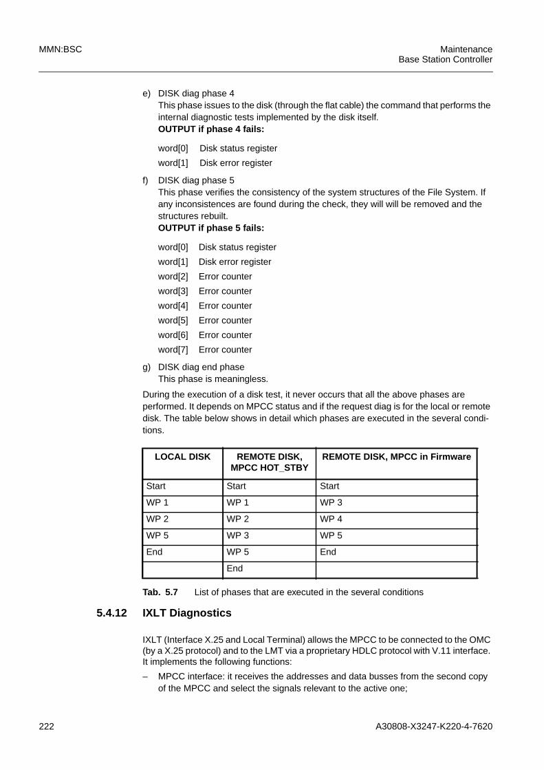
222 A30808-X3247-K220-4-7620
MMN:BSC MaintenanceBase Station Controller
e) DISK diag phase 4This phase issues to the disk (through the flat cable) the command that performs theinternal diagnostic tests implemented by the disk itself.OUTPUT if phase 4 fails:
f) DISK diag phase 5This phase verifies the consistency of the system structures of the File System. Ifany inconsistences are found during the check, they will will be removed and thestructures rebuilt.OUTPUT if phase 5 fails:
g) DISK diag end phaseThis phase is meaningless.
During the execution of a disk test, it never occurs that all the above phases areperformed. It depends on MPCC status and if the request diag is for the local or remotedisk. The table below shows in detail which phases are executed in the several condi-tions.
5.4.12 IXLT Diagnostics
IXLT (Interface X.25 and Local Terminal) allows the MPCC to be connected to the OMC(by a X.25 protocol) and to the LMT via a proprietary HDLC protocol with V.11 interface.It implements the following functions:
– MPCC interface: it receives the addresses and data busses from the second copyof the MPCC and select the signals relevant to the active one;
word[0] Disk status register
word[1] Disk error register
word[0] Disk status register
word[1] Disk error register
word[2] Error counter
word[3] Error counter
word[4] Error counter
word[5] Error counter
word[6] Error counter
word[7] Error counter
LOCAL DISK REMOTE DISK,MPCC HOT_STBY
REMOTE DISK, MPCC in Firmware
Start Start Start
WP 1 WP 1 WP 3
WP 2 WP 2 WP 4
WP 5 WP 3 WP 5
End WP 5 End
End
Tab. 5.7 List of phases that are executed in the several conditions
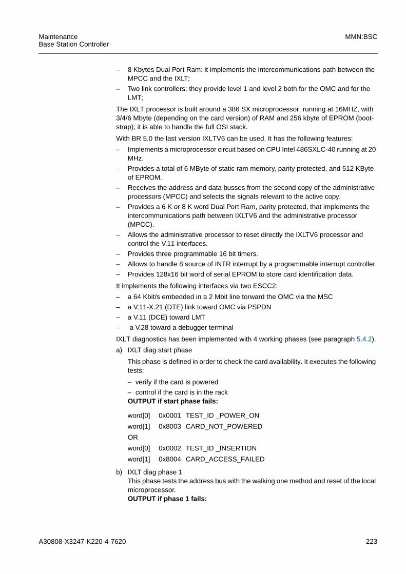
A30808-X3247-K220-4-7620 223
MaintenanceBase Station Controller
MMN:BSC
– 8 Kbytes Dual Port Ram: it implements the intercommunications path between theMPCC and the IXLT;
– Two link controllers: they provide level 1 and level 2 both for the OMC and for theLMT;
The IXLT processor is built around a 386 SX microprocessor, running at 16MHZ, with3/4/6 Mbyte (depending on the card version) of RAM and 256 kbyte of EPROM (boot-strap); it is able to handle the full OSI stack.
With BR 5.0 the last version IXLTV6 can be used. It has the following features:
– Implements a microprocessor circuit based on CPU Intel 486SXLC-40 running at 20MHz.
– Provides a total of 6 MByte of static ram memory, parity protected, and 512 KByteof EPROM.
– Receives the address and data busses from the second copy of the administrativeprocessors (MPCC) and selects the signals relevant to the active copy.
– Provides a 6 K or 8 K word Dual Port Ram, parity protected, that implements theintercommunications path between IXLTV6 and the administrative processor(MPCC).
– Allows the administrative processor to reset directly the IXLTV6 processor andcontrol the V.11 interfaces.
– Provides three programmable 16 bit timers.
– Allows to handle 8 source of INTR interrupt by a programmable interrupt controller.
– Provides 128x16 bit word of serial EPROM to store card identification data.
It implements the following interfaces via two ESCC2:
– a 64 Kbit/s embedded in a 2 Mbit line torward the OMC via the MSC
– a V.11-X.21 (DTE) link toward OMC via PSPDN
– a V.11 (DCE) toward LMT
– a V.28 toward a debugger terminal
IXLT diagnostics has been implemented with 4 working phases (see paragraph 5.4.2).
a) IXLT diag start phase
This phase is defined in order to check the card availability. It executes the followingtests:
– verify if the card is powered
– control if the card is in the rackOUTPUT if start phase fails:
b) IXLT diag phase 1This phase tests the address bus with the walking one method and reset of the localmicroprocessor.OUTPUT if phase 1 fails:
word[0] 0x0001 TEST_ID _POWER_ON
word[1] 0x8003 CARD_NOT_POWERED
OR
word[0] 0x0002 TEST_ID _INSERTION
word[1] 0x8004 CARD_ACCESS_FAILED
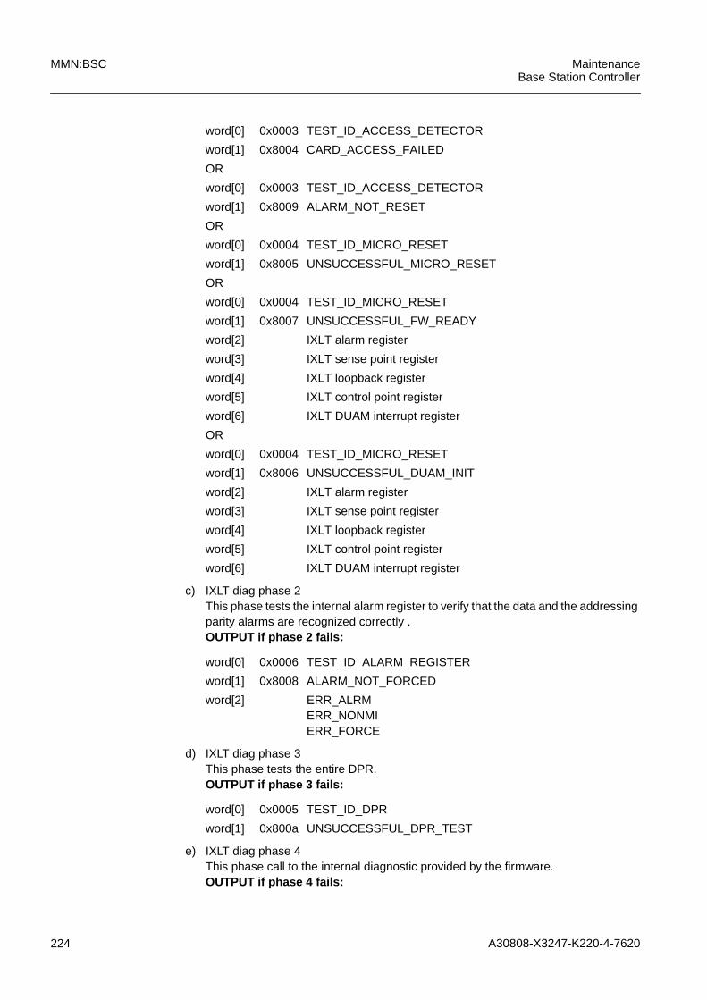
224 A30808-X3247-K220-4-7620
MMN:BSC MaintenanceBase Station Controller
c) IXLT diag phase 2This phase tests the internal alarm register to verify that the data and the addressingparity alarms are recognized correctly .OUTPUT if phase 2 fails:
d) IXLT diag phase 3This phase tests the entire DPR.OUTPUT if phase 3 fails:
e) IXLT diag phase 4This phase call to the internal diagnostic provided by the firmware.OUTPUT if phase 4 fails:
word[0] 0x0003 TEST_ID_ACCESS_DETECTOR
word[1] 0x8004 CARD_ACCESS_FAILED
OR
word[0] 0x0003 TEST_ID_ACCESS_DETECTOR
word[1] 0x8009 ALARM_NOT_RESET
OR
word[0] 0x0004 TEST_ID_MICRO_RESET
word[1] 0x8005 UNSUCCESSFUL_MICRO_RESET
OR
word[0] 0x0004 TEST_ID_MICRO_RESET
word[1] 0x8007 UNSUCCESSFUL_FW_READY
word[2] IXLT alarm register
word[3] IXLT sense point register
word[4] IXLT loopback register
word[5] IXLT control point register
word[6] IXLT DUAM interrupt register
OR
word[0] 0x0004 TEST_ID_MICRO_RESET
word[1] 0x8006 UNSUCCESSFUL_DUAM_INIT
word[2] IXLT alarm register
word[3] IXLT sense point register
word[4] IXLT loopback register
word[5] IXLT control point register
word[6] IXLT DUAM interrupt register
word[0] 0x0006 TEST_ID_ALARM_REGISTER
word[1] 0x8008 ALARM_NOT_FORCED
word[2] ERR_ALRMERR_NONMIERR_FORCE
word[0] 0x0005 TEST_ID_DPR
word[1] 0x800a UNSUCCESSFUL_DPR_TEST
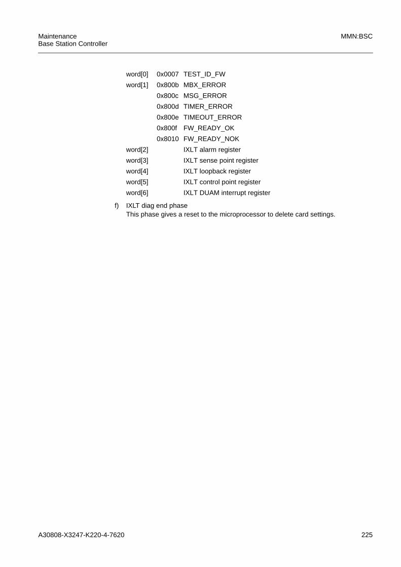
A30808-X3247-K220-4-7620 225
MaintenanceBase Station Controller
MMN:BSC
f) IXLT diag end phaseThis phase gives a reset to the microprocessor to delete card settings.
word[0] 0x0007 TEST_ID_FW
word[1] 0x800b MBX_ERROR
0x800c MSG_ERROR
0x800d TIMER_ERROR
0x800e TIMEOUT_ERROR
0x800f FW_READY_OK
0x8010 FW_READY_NOK
word[2] IXLT alarm register
word[3] IXLT sense point register
word[4] IXLT loopback register
word[5] IXLT control point register
word[6] IXLT DUAM interrupt register
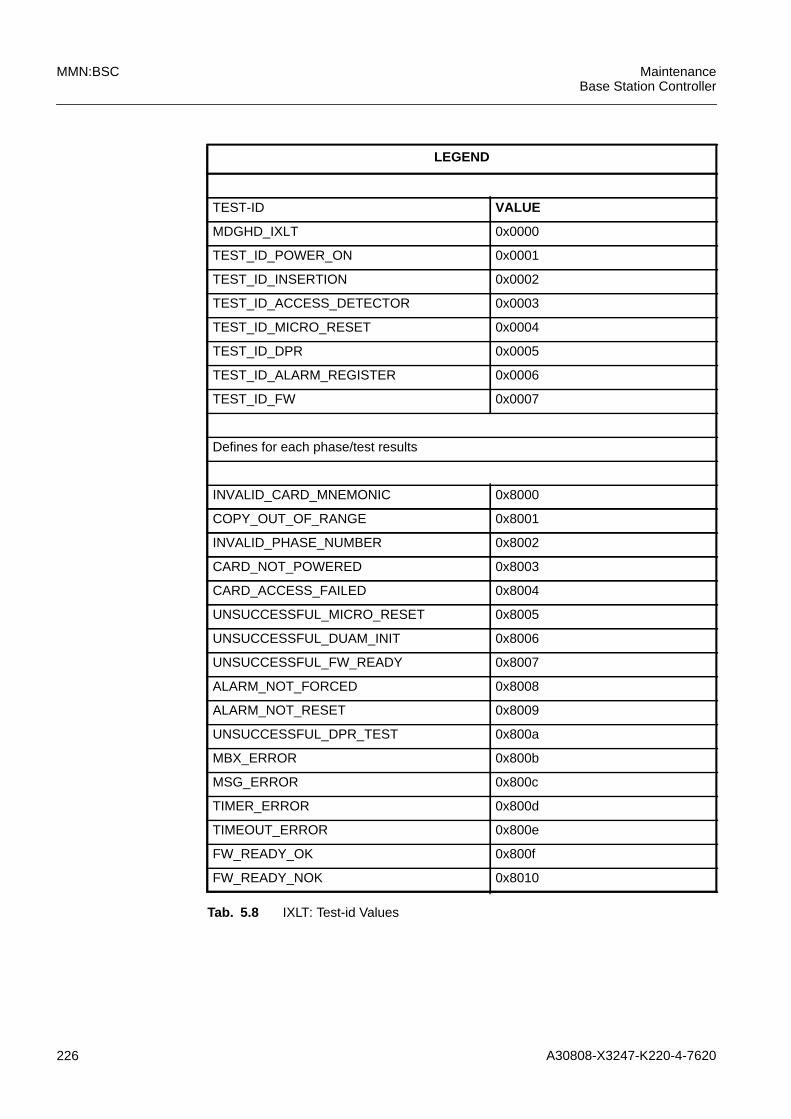
226 A30808-X3247-K220-4-7620
MMN:BSC MaintenanceBase Station Controller
LEGEND
TEST-ID VALUE
MDGHD_IXLT 0x0000
TEST_ID_POWER_ON 0x0001
TEST_ID_INSERTION 0x0002
TEST_ID_ACCESS_DETECTOR 0x0003
TEST_ID_MICRO_RESET 0x0004
TEST_ID_DPR 0x0005
TEST_ID_ALARM_REGISTER 0x0006
TEST_ID_FW 0x0007
Defines for each phase/test results
INVALID_CARD_MNEMONIC 0x8000
COPY_OUT_OF_RANGE 0x8001
INVALID_PHASE_NUMBER 0x8002
CARD_NOT_POWERED 0x8003
CARD_ACCESS_FAILED 0x8004
UNSUCCESSFUL_MICRO_RESET 0x8005
UNSUCCESSFUL_DUAM_INIT 0x8006
UNSUCCESSFUL_FW_READY 0x8007
ALARM_NOT_FORCED 0x8008
ALARM_NOT_RESET 0x8009
UNSUCCESSFUL_DPR_TEST 0x800a
MBX_ERROR 0x800b
MSG_ERROR 0x800c
TIMER_ERROR 0x800d
TIMEOUT_ERROR 0x800e
FW_READY_OK 0x800f
FW_READY_NOK 0x8010
Tab. 5.8 IXLT: Test-id Values
A30808-X3247-K220-4-7620 227
MaintenanceBase Station Controller
MMN:BSC
5.4.13 PPCU Diagnostics
The PPCU card is a peripheral processing board which allows the GPRS feature in theSBS. Its basic functions are channel resource allocation and protocol conversionbetween the Abis and the Gb interface.
One BSC can be equipped with 4 PPCU board. The boards are subdivided into two pairswith redundancy 1+1. Each pair of redundant PPCUs identifies a PCU serving an inde-pendent GPRS area.
The perform-test command is addressed to a PPCU x, where x is the absolute numberof the PPCU: the first two copies refer to the first PCU, the last two to the second one.
The MPCC controls the PPCU via the UBEX, for operating and maintenance purposes;the TDPC exchanges messages with the PPCU through a 8 Kbyte dual port RAM; theselection of the active copy of the TDPC is under the control of the MPCC.
One PCU (a couple of 1+1 redounded PPCU) has access to a whole 2 Mb/s flux towardsSN16. This bandwidth, composed of 32 time slots at 64 Kb/s, is shared by the four DSPsof the ABIC processor (which work on 16 Kb/s time slots connected to the BTS) and bythe GbIC (connected via frame relays at 64 Kb/s to the SGSN). The PPCU under test,however, and in general the PPCU that is not providing service, is disconnected fromthe SN.
PPCU diagnostics have been implemented with 5 working phases (see paragraph5.4.2). The phases 1, 2, 3 are in effect performed by the PCUC software, but arerequested by the MPCC software via a unique command (MPCC DUAM). The outputresult towards MPCC (about 230 bytes) contains the information regarding all these 3phases. The MPCC diagnostic software splits this information up and formats it for theoutput result.
a) PPCU diag start phaseThis phase checks NTW outages and TDPC outages, loopback tests, CPU resets,firmware auto-diagnosis, software loads.OUTPUT if start phase fails :
word[0] Source item (1)
word[1] Source code line
word[2] Error code (2)
228 A30808-X3247-K220-4-7620
MMN:BSC MaintenanceBase Station Controller
word[3] Cases:a) Firmware autodiagnostics failure(meaning of possible bit values):0 = test failure of Pentium RAM (64 MB);1 = test failure of DSP 0 internal RAM (64KB);2 = test failure of DSP 1 internal RAM (64KB);3 = test failure of DSP 2 internal RAM (64 KB);4 = test failure of DSP 2 internal RAM (64 KB);5 = test failure concerning RAM on Motorola (2MB);6 = test failure of TDPC-PPCU DUAM)
b) Unsuccessful Start / Force Out of Service Command toPCUC:Low byte -> Byte 0 of PCUC answer = 0x36 (Start/Force Outof Service Code);High byte -> Byte 1 = 0x2 (unsuccessful)
c) Unsuccessful software executable load: cause of failure(possible nack causes:3 = Failed11 = No File Found16 = Card Problem19 = Load In Progress)
d) Unsuccessful patches load: list of possible nack causes:3 = Failed (patch file probably corrupted)19 = Another Load In Progress21 = File System failure23 = Load Aborted
e) Time out during a MPCC - PCUC command, TDPCoutage and all other causes of error:UBEX Register "mirror" (stored copy of last written values)(low byte)Saved bit mask of PPCU last alarms read on UBEX register (ifany) (high byte)
word[4] Cases: firmware diagnostics failure, unsuccessful Start /Force Out Of Service command to PCUC:Byte 2 of PCUC answer (low byte);Byte 3 of PCUC answer (high byte)
In case of time out during a MPCC - PCUC command, TDPCoutage and all other causes of error:software semaphore (MPCC -> PCUC) on MPCC-PCUCDUAM (low byte)First byte of PPCU DH command to PPCU Agent on PCUC(high byte)
A30808-X3247-K220-4-7620 229
MaintenanceBase Station Controller
MMN:BSC
b) PPCU diag phase 1This phase tests the hardware circuitry that can be interfaced by the PCUC. Itperforms a read/write check on the TDPC and MPCC DUAM (checks for parityalarms). It performs a fast access test of the Qspan, (checks for access alarms).Notice that the phase 3, which checks the GbIC, indirectly performs a test of theQspan. The Qspan is the Bus Bridge which allows communication between thePCUC and the GbIC.OUTPUT if phase 1 fails:
word[5] Cases: firmware diagnostics failure, unsuccessful Start /Force Out Of Service command to PCUC:Byte 4 of PCUC answer (low byte);Byte 5 (high byte)
In case of time out during a MPCC - PCUC command, TDPCoutage and all other causes of error:Second byte of PPCU DH command to PPCU Agent onPCUC (low byte);Third byte of PPCU DH command to PPCU Agent on PCUC(high byte)
word[6] Cases: firmware diagnostics failure, unsuccessful Start /Force Out Of Service command to PCUC:Byte 6 of PCUC answer (low byte);Byte 7 (high byte)
In case of time out during a MPCC - PCUC command, TDPCoutage and all other causes of error:software semaphore (PCUC -> MPCC) on MPCC-PCUCDUAM (low byte);first byte of PPCU Agent answer to PPCU DH on MPCC (highbyte)
word[7] Cases: firmware diagnostics failure, unsuccessful Start /Force Out Of Service command to PCUC:Byte 8 of PCUC answer (low byte);Byte 9 (high byte)
In case of time out during a MPCC - PCUC command, TDPCoutage and all other causes of error:Second byte of PPCU Agent answer to PPCU DH on MPCC(low byte)Third byte of PPCU Agent answer to PPCU DH on MPCC(high byte)
230 A30808-X3247-K220-4-7620
MMN:BSC MaintenanceBase Station Controller
word[0] If a problem was detected by diagnostic test:Bit mask showing problem area:00000100 means MPCC DUAM failure;00001000 means TDPC DUAM failure.
If a fault was detected during MPCC-PCUC interface(concerning hardware or firmware or TDPC-PPCU DUAM):Source item (high byte) and error code (low byte).
word[1 If a problem was detected by diagnostic test:Stored copy of last value written on UBEX register (low byte)and stored copy of last alarms (if any) read on UBEX register(high byte)
If a fault was detected during MPCC-PCUC interface(concerning hardware or firmware or TDPC-PPCU DUAM):Source code line
word[2] If a problem was detected by diagnostic test:software semaphore (MPCC -> PCUC) on MPCC-PCUCDUAM (low byte)First byte of PPCU DH command to PPCU Agent on PCUC(high byte)
If a fault was detected during MPCC-PCUC interface(concerning hardware or firmware or TDPC-PPCU DUAM):Stored copy of last value written on UBEX register (low byte)and stored copy of last alarms (if any) read on UBEX register(high byte)
word[3] If a problem was detected by diagnostic test:Second byte of PPCU DH command to PPCU Agent onPCUC (low byte);third byte of PPCU DH command to PPCU Agent on PCUC(high byte)
If a fault was detected during MPCC-PCUC interface(concerning hardware or firmware or TDPC-PPCU DUAM):software semaphore (MPCC -> PCUC) on MPCC-PCUCDUAM (low byte)First byte of PPCU DH command to PPCU Agent on PCUC(high byte)
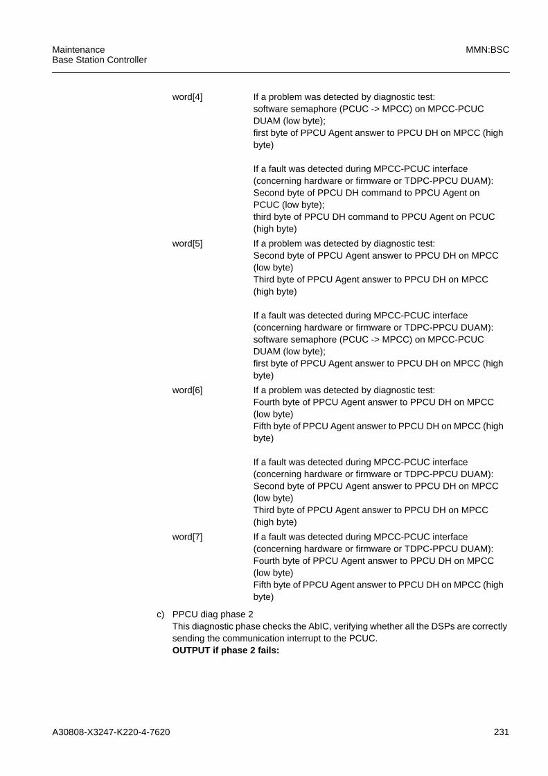
A30808-X3247-K220-4-7620 231
MaintenanceBase Station Controller
MMN:BSC
c) PPCU diag phase 2This diagnostic phase checks the AbIC, verifying whether all the DSPs are correctlysending the communication interrupt to the PCUC.OUTPUT if phase 2 fails:
word[4] If a problem was detected by diagnostic test:software semaphore (PCUC -> MPCC) on MPCC-PCUCDUAM (low byte);first byte of PPCU Agent answer to PPCU DH on MPCC (highbyte)
If a fault was detected during MPCC-PCUC interface(concerning hardware or firmware or TDPC-PPCU DUAM):Second byte of PPCU DH command to PPCU Agent onPCUC (low byte);third byte of PPCU DH command to PPCU Agent on PCUC(high byte)
word[5] If a problem was detected by diagnostic test:Second byte of PPCU Agent answer to PPCU DH on MPCC(low byte)Third byte of PPCU Agent answer to PPCU DH on MPCC(high byte)
If a fault was detected during MPCC-PCUC interface(concerning hardware or firmware or TDPC-PPCU DUAM):software semaphore (PCUC -> MPCC) on MPCC-PCUCDUAM (low byte);first byte of PPCU Agent answer to PPCU DH on MPCC (highbyte)
word[6] If a problem was detected by diagnostic test:Fourth byte of PPCU Agent answer to PPCU DH on MPCC(low byte)Fifth byte of PPCU Agent answer to PPCU DH on MPCC (highbyte)
If a fault was detected during MPCC-PCUC interface(concerning hardware or firmware or TDPC-PPCU DUAM):Second byte of PPCU Agent answer to PPCU DH on MPCC(low byte)Third byte of PPCU Agent answer to PPCU DH on MPCC(high byte)
word[7] If a fault was detected during MPCC-PCUC interface(concerning hardware or firmware or TDPC-PPCU DUAM):Fourth byte of PPCU Agent answer to PPCU DH on MPCC(low byte)Fifth byte of PPCU Agent answer to PPCU DH on MPCC (highbyte)

232 A30808-X3247-K220-4-7620
MMN:BSC MaintenanceBase Station Controller
word[0] If a problem was detected by diagnostic test:Bit mask showing problem area:00000001 means AbIC failure.0x0020 means loop test on AbIS interface of DSP processorsfailed: more in details, one or more AbIC received someuncorrect PCU Frames from PLD closed in loop mode.
If a fault was detected during MPCC-PCUC interface(concerning hardware or firmware or TDPC-PPCU DUAM):Source item (high byte) and error code (low byte).
word[1] If a problem was detected by diagnostic test:a) if AbIS loop test failed: Bit mask of failed DSP (for example,0x0005 means DSP-0 (0X01) and DSP-2 (0x04)).b) otherwise: stored copy of last value written on UBEXregister (low byte) and stored copy of last alarms (if any) readon UBEX register (high byte)
If a fault was detected during MPCC-PCUC interface(concerning hardware or firmware or TDPC-PPCU DUAM):Source code line
word[2] If a problem was detected by diagnostic test:a) if AbIS loop test failed: Bit mask of PDT channels involvedin failure (AbIC-0 -->PDT 0-15)b) otherwise: software semaphore (MPCC -> PCUC) onMPCC-PCUC DUAM (low byte)First byte of PPCU DH command to PPCU Agent on PCUC(high byte)
If a fault was detected during MPCC-PCUC interface(concerning hardware or firmware or TDPC-PPCU DUAM):Stored copy of last value written on UBEX register (low byte)and stored copy of last alarms (if any) read on UBEX register(high byte)
word[3] If a problem was detected by diagnostic test:a) if AbIS loop test failed: Bit mask of PDT channels involvedin failure (AbIC-1 -->PDT 16-31)b) otherwise: second byte of PPCU DH command to PPCUAgent on PCUC (low byte);third byte of PPCU DH command to PPCU Agent on PCUC(high byte)
If a fault was detected during MPCC-PCUC interface(concerning hardware or firmware or TDPC-PPCU DUAM):software semaphore (MPCC -> PCUC) on MPCC-PCUCDUAM (low byte)First byte of PPCU DH command to PPCU Agent on PCUC(high byte).
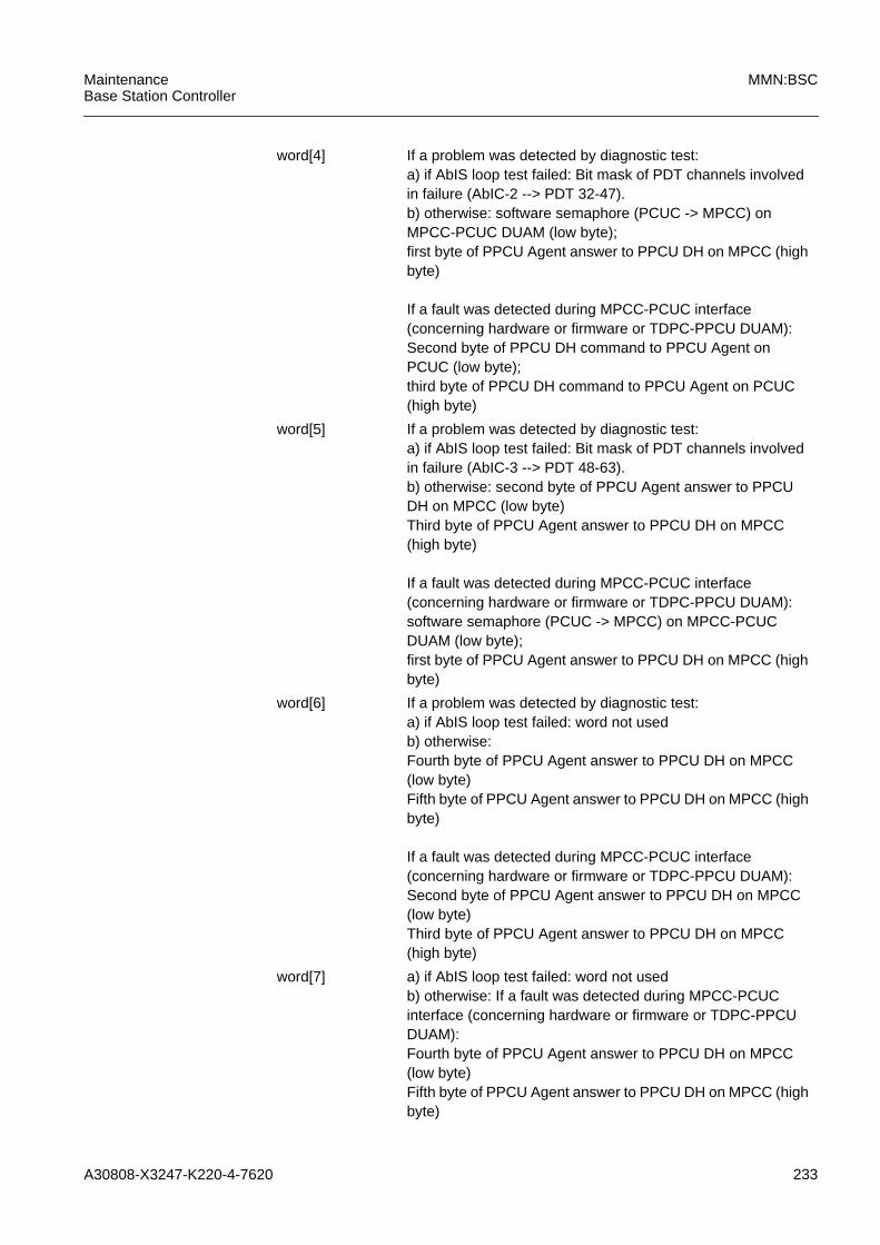
A30808-X3247-K220-4-7620 233
MaintenanceBase Station Controller
MMN:BSC
word[4] If a problem was detected by diagnostic test:a) if AbIS loop test failed: Bit mask of PDT channels involvedin failure (AbIC-2 --> PDT 32-47).b) otherwise: software semaphore (PCUC -> MPCC) onMPCC-PCUC DUAM (low byte);first byte of PPCU Agent answer to PPCU DH on MPCC (highbyte)
If a fault was detected during MPCC-PCUC interface(concerning hardware or firmware or TDPC-PPCU DUAM):Second byte of PPCU DH command to PPCU Agent onPCUC (low byte);third byte of PPCU DH command to PPCU Agent on PCUC(high byte)
word[5] If a problem was detected by diagnostic test:a) if AbIS loop test failed: Bit mask of PDT channels involvedin failure (AbIC-3 --> PDT 48-63).b) otherwise: second byte of PPCU Agent answer to PPCUDH on MPCC (low byte)Third byte of PPCU Agent answer to PPCU DH on MPCC(high byte)
If a fault was detected during MPCC-PCUC interface(concerning hardware or firmware or TDPC-PPCU DUAM):software semaphore (PCUC -> MPCC) on MPCC-PCUCDUAM (low byte);first byte of PPCU Agent answer to PPCU DH on MPCC (highbyte)
word[6] If a problem was detected by diagnostic test:a) if AbIS loop test failed: word not usedb) otherwise:Fourth byte of PPCU Agent answer to PPCU DH on MPCC(low byte)Fifth byte of PPCU Agent answer to PPCU DH on MPCC (highbyte)
If a fault was detected during MPCC-PCUC interface(concerning hardware or firmware or TDPC-PPCU DUAM):Second byte of PPCU Agent answer to PPCU DH on MPCC(low byte)Third byte of PPCU Agent answer to PPCU DH on MPCC(high byte)
word[7] a) if AbIS loop test failed: word not usedb) otherwise: If a fault was detected during MPCC-PCUCinterface (concerning hardware or firmware or TDPC-PPCUDUAM):Fourth byte of PPCU Agent answer to PPCU DH on MPCC(low byte)Fifth byte of PPCU Agent answer to PPCU DH on MPCC (highbyte)
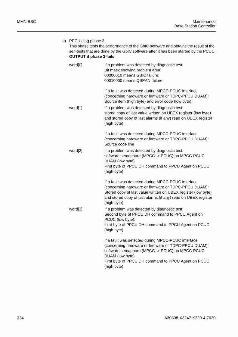
234 A30808-X3247-K220-4-7620
MMN:BSC MaintenanceBase Station Controller
d) PPCU diag phase 3This phase tests the performance of the GbIC software and obtains the result of theself-tests that are done by the GbIC software after it has been started by the PCUC.OUTPUT if phase 3 fails:
word[0] If a problem was detected by diagnostic test:Bit mask showing problem area:00000010 means GBIC failure;00010000 means QSPAN failure.
If a fault was detected during MPCC-PCUC interface(concerning hardware or firmware or TDPC-PPCU DUAM):Source item (high byte) and error code (low byte).
word[1] If a problem was detected by diagnostic test:stored copy of last value written on UBEX register (low byte)and stored copy of last alarms (if any) read on UBEX register(high byte)
If a fault was detected during MPCC-PCUC interface(concerning hardware or firmware or TDPC-PPCU DUAM):Source code line
word[2] If a problem was detected by diagnostic test:software semaphore (MPCC -> PCUC) on MPCC-PCUCDUAM (low byte)First byte of PPCU DH command to PPCU Agent on PCUC(high byte)
If a fault was detected during MPCC-PCUC interface(concerning hardware or firmware or TDPC-PPCU DUAM):Stored copy of last value written on UBEX register (low byte)and stored copy of last alarms (if any) read on UBEX register(high byte)
word[3] If a problem was detected by diagnostic test:Second byte of PPCU DH command to PPCU Agent onPCUC (low byte);third byte of PPCU DH command to PPCU Agent on PCUC(high byte)
If a fault was detected during MPCC-PCUC interface(concerning hardware or firmware or TDPC-PPCU DUAM):software semaphore (MPCC -> PCUC) on MPCC-PCUCDUAM (low byte)First byte of PPCU DH command to PPCU Agent on PCUC(high byte)

A30808-X3247-K220-4-7620 235
MaintenanceBase Station Controller
MMN:BSC
e) PPCU diag end phaseThe only role of this phase is to put the PPCU in the off-line state. It does not containany diagnostic information.(1) identifier of source item where problem took place:
word[4] If a problem was detected by diagnostic testsoftware semaphore (PCUC -> MPCC) on MPCC-PCUCDUAM (low byte);first byte of PPCU Agent answer to PPCU DH on MPCC (highbyte)
If a fault was detected during MPCC-PCUC interface(concerning hardware or firmware or TDPC-PPCU DUAM):Second byte of PPCU DH command to PPCU Agent onPCUC (low byte);third byte of PPCU DH command to PPCU Agent on PCUC(high byte)
word[5] If a problem was detected by diagnostic test:Second byte of PPCU Agent answer to PPCU DH on MPCC(low byte)Third byte of PPCU Agent answer to PPCU DH on MPCC(high byte)
If a fault was detected during MPCC-PCUC interface(concerning hardware or firmware or TDPC-PPCU DUAM):software semaphore (PCUC -> MPCC) on MPCC-PCUCDUAM (low byte);first byte of PPCU Agent answer to PPCU DH on MPCC (highbyte)
word[6] If a problem was detected by diagnostic test:Fourth byte of PPCU Agent answer to PPCU DH on MPCC(low byte)Fifth byte of PPCU Agent answer to PPCU DH on MPCC (highbyte)
If a fault was detected during MPCC-PCUC interface(concerning hardware or firmware or TDPC-PPCU DUAM):Second byte of PPCU Agent answer to PPCU DH on MPCC(low byte)Third byte of PPCU Agent answer to PPCU DH on MPCC(high byte)
word[7] If a fault was detected during MPCC-PCUC interface(concerning hardware or firmware or TDPC-PPCU DUAM):Fourth byte of PPCU Agent answer to PPCU DH on MPCC(low byte)Fifth byte of PPCU Agent answer to PPCU DH on MPCC (highbyte)

236 A30808-X3247-K220-4-7620
MMN:BSC MaintenanceBase Station Controller
LEGEND
(1) Identifier of source item where problem occurred
1 DHXXDCCH
2 DHXXDCDE
3 DHXXDCEH
4 DHXXDCSA
5 DHXXDCSM
6 DHXXDCTH
7 DHXXDDDI
8 DHXXDDHD
9 DHXXGSUT
10 DHXXININ
11 DGHDXXDP
12 DHXXDDPU
(2) Error code description
NTW_outage_test: 0001h
TDPC_outage_test: 0002h
Loop_test: 00e3h (access to loopback reg.)00e4h (NMI)
FW_diagnose_test: 00e2h (diagnosis failed)008ah (firmware time out)
SW_load_test: 000ch (load failed)0014h (file system problem)
Operating system problems: 000ah (mailbox creation failed, null DH answer)
Tasks interface problems: 000bh (PPxx DH time-out during load function)
Software start: 0080h (software nack answer) or 008ah (softwaretime out)
Forcing Out Of Service idlestatus:
0081h (software nack answer) or 008ah (softwaretime out)
Alarm raising during cardaccess:
008ch (time-out expired in command sending)00a0h (alarm detected during reading operation ofsoftware answer)
Tab. 5.9 PPCU: Test-id Values
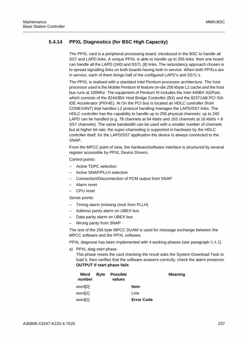
A30808-X3247-K220-4-7620 237
MaintenanceBase Station Controller
MMN:BSC
5.4.14 PPXL Diagnostics (for BSC High Capacity)
The PPXL card is a peripheral processing board, introduced in the BSC to handle allSS7 and LAPD links. A unique PPXL is able to handle up to 256 links: then one boardcan handle all the LAPD (240) and SS7L (8) links. The redundancy approach chosen isto spread signalling links on both boards having both in service. When both PPXLs arein service, each of them brings half of the configured LAPD’s and SS7L’s.
The PPXL is realised with a standard Intel Pentium processor architecture. The hostprocessor used is the Mobile Pentium III feature on-die 256 kbyte L2 cache and the hostbus runs at 100Mhz. The equipment of Pentium III includes the Intel 440BX AGPset,which consists of the 82443BX Host Bridge Controller (BX) and the 82371AB PCI ISAIDE Accelerator (PIIX4E). At On the PCI bus is located an HDLC controller (fromCONEXANT) that handles L2 protocol handling manages the LAPD/SS7 links. TheHDLC controller has the capability to handle up to 256 physical channels; up to 240LAPD can be handled (e.g. 78 channels at 64 kbit/s and 162 channels at 16 kbit/s + 8SS7 channels). The same bandwidth can be used with a smaller number of channelsbut at higher bit rate; the super-channeling is supported in hardware by the HDLCcontroller itself, for the LAPD/SS7 application the device is always connected to theSNAP.
From the MPCC point of view, the hardware/software interface is structured by severalregister accessible by PPXL Device Drivers.
Control points:
– Active TDPC selection
– Active SNAP/PLLH selection
– Connection/Disconnection of PCM output from SNAP
– Alarm reset
– CPU reset
Sense points:
– Timing alarm (missing clock from PLLH)
– Address parity alarm on UBEX bus
– Data parity alarm on UBEX bus
– Wrong parity from SNAP
The rest of the 256 byte MPCC DUAM is used for message exchange between theMPCC software and the PPXL software.
PPXL diagnose has been implemented with 4 working phases (see paragraph 5.4.2).
a) PPXL diag start phaseThis phase resets the card checking the result asks the System Download Task toload it, then verifies that the software answers correctly, check the alarm presence.OUTPUT if start phase fails :
Wordnumber
Byte Possiblevalues
Meaning
word[0] Item
word[1] Line
word[2] Error Code
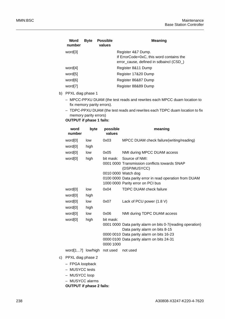
238 A30808-X3247-K220-4-7620
MMN:BSC MaintenanceBase Station Controller
b) PPXL diag phase 1
– MPCC-PPXU DUAM (the test reads and rewrites each MPCC duam location tofix memory parity errors).
– TDPC-PPXU DUAM (the test reads and rewrites each TDPC duam location to fixmemory parity errors)
OUTPUT if phase 1 fails:
c) PPXL diag phase 2
– FPGA loopback
– MUSYCC tests
– MUSYCC loop
– MUSYCC alarmsOUTPUT if phase 2 fails:
word[3] Register 4&7 Dump.If ErrorCode=0xC, this word contains theerror_cause, defined in sdbaincl (CSD_)
word[4] Register 8&11 Dump
word[5] Register 17&20 Dump
word[6] Register 86&87 Dump
word[7] Register 88&89 Dump
Wordnumber
Byte Possiblevalues
Meaning
wordnumber
byte possiblevalues
meaning
word[0] low 0x03 MPCC DUAM check failure(writing/reading)
word[0] high
word[0] low 0x05 NMI during MPCC DUAM access
word[0] high bit mask:0001 0000
0010 00000100 00001000 0000
Source of NMI:Transmission conflicts towards SNAP(DSP/MUSYCC)Watch dogData parity error in read operation from DUAMParity error on PCI bus
word[0] low 0x04 TDPC DUAM check failure
word[0] high
word[0] low 0x07 Lack of PCU power (1.8 V)
word[0] high
word[0] low 0x06 NMI during TDPC DUAM access
word[0] high bit mask:0001 0000
0000 00100000 01000000 1000
Data parity alarm on bits 0-7(reading operation)Data parity alarm on bits 8-15Data parity alarm on bits 16-23Data parity alarm on bits 24-31
word[1...7] low/high not used not used
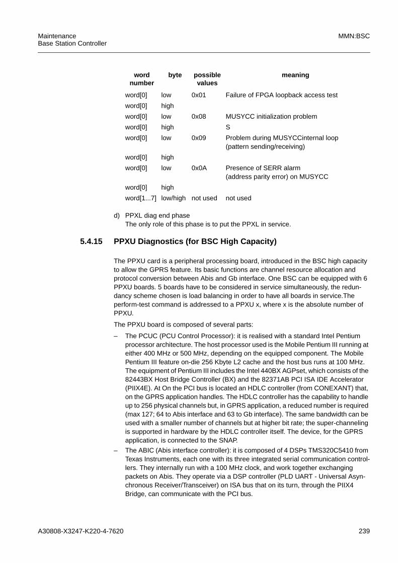
A30808-X3247-K220-4-7620 239
MaintenanceBase Station Controller
MMN:BSC
d) PPXL diag end phaseThe only role of this phase is to put the PPXL in service.
5.4.15 PPXU Diagnostics (for BSC High Capacity)
The PPXU card is a peripheral processing board, introduced in the BSC high capacityto allow the GPRS feature. Its basic functions are channel resource allocation andprotocol conversion between Abis and Gb interface. One BSC can be equipped with 6PPXU boards. 5 boards have to be considered in service simultaneously, the redun-dancy scheme chosen is load balancing in order to have all boards in service.Theperform-test command is addressed to a PPXU x, where x is the absolute number ofPPXU.
The PPXU board is composed of several parts:
– The PCUC (PCU Control Processor): it is realised with a standard Intel Pentiumprocessor architecture. The host processor used is the Mobile Pentium III running ateither 400 MHz or 500 MHz, depending on the equipped component. The MobilePentium III feature on-die 256 Kbyte L2 cache and the host bus runs at 100 MHz.The equipment of Pentium III includes the Intel 440BX AGPset, which consists of the82443BX Host Bridge Controller (BX) and the 82371AB PCI ISA IDE Accelerator(PIIX4E). At On the PCI bus is located an HDLC controller (from CONEXANT) that,on the GPRS application handles. The HDLC controller has the capability to handleup to 256 physical channels but, in GPRS application, a reduced number is required(max 127; 64 to Abis interface and 63 to Gb interface). The same bandwidth can beused with a smaller number of channels but at higher bit rate; the super-channelingis supported in hardware by the HDLC controller itself. The device, for the GPRSapplication, is connected to the SNAP.
– The ABIC (Abis interface controller): it is composed of 4 DSPs TMS320C5410 fromTexas Instruments, each one with its three integrated serial communication control-lers. They internally run with a 100 MHz clock, and work together exchangingpackets on Abis. They operate via a DSP controller (PLD UART - Universal Asyn-chronous Receiver/Transceiver) on ISA bus that on its turn, through the PIIX4Bridge, can communicate with the PCI bus.
wordnumber
byte possiblevalues
meaning
word[0] low 0x01 Failure of FPGA loopback access test
word[0] high
word[0] low 0x08 MUSYCC initialization problem
word[0] high S
word[0] low 0x09 Problem during MUSYCCinternal loop(pattern sending/receiving)
word[0] high
word[0] low 0x0A Presence of SERR alarm(address parity error) on MUSYCC
word[0] high
word[1...7] low/high not used not used
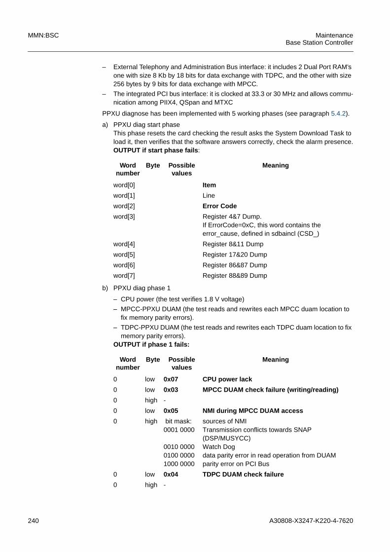
240 A30808-X3247-K220-4-7620
MMN:BSC MaintenanceBase Station Controller
– External Telephony and Administration Bus interface: it includes 2 Dual Port RAM’sone with size 8 Kb by 18 bits for data exchange with TDPC, and the other with size256 bytes by 9 bits for data exchange with MPCC.
– The integrated PCI bus interface: it is clocked at 33.3 or 30 MHz and allows commu-nication among PIIX4, QSpan and MTXC
PPXU diagnose has been implemented with 5 working phases (see paragraph 5.4.2).
a) PPXU diag start phaseThis phase resets the card checking the result asks the System Download Task toload it, then verifies that the software answers correctly, check the alarm presence.OUTPUT if start phase fails :
b) PPXU diag phase 1
– CPU power (the test verifies 1.8 V voltage)
– MPCC-PPXU DUAM (the test reads and rewrites each MPCC duam location tofix memory parity errors).
– TDPC-PPXU DUAM (the test reads and rewrites each TDPC duam location to fixmemory parity errors).
OUTPUT if phase 1 fails:
Wordnumber
Byte Possiblevalues
Meaning
word[0] Item
word[1] Line
word[2] Error Code
word[3] Register 4&7 Dump.If ErrorCode=0xC, this word contains theerror_cause, defined in sdbaincl (CSD_)
word[4] Register 8&11 Dump
word[5] Register 17&20 Dump
word[6] Register 86&87 Dump
word[7] Register 88&89 Dump
Wordnumber
Byte Possiblevalues
Meaning
0 low 0x07 CPU power lack
0 low 0x03 MPCC DUAM check failure (writing/reading)
0 high -
0 low 0x05 NMI during MPCC DUAM access
0 high bit mask:0001 0000
0010 00000100 00001000 0000
sources of NMITransmission conflicts towards SNAP(DSP/MUSYCC)Watch Dogdata parity error in read operation from DUAMparity error on PCI Bus
0 low 0x04 TDPC DUAM check failure
0 high -
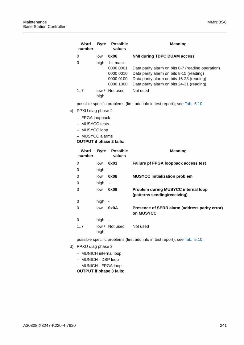
A30808-X3247-K220-4-7620 241
MaintenanceBase Station Controller
MMN:BSC
possible specific problems (first add info in test report); see Tab. 5.10.
c) PPXU diag phase 2
– FPGA loopback
– MUSYCC tests
– MUSYCC loop
– MUSYCC alarmsOUTPUT if phase 2 fails:
possible specific problems (first add info in test report); see Tab. 5.10.
d) PPXU diag phase 3
– MUNICH internal loop
– MUNICH - DSP loop
– MUNICH - FPGA loopOUTPUT if phase 3 fails:
0 low 0x06 NMI during TDPC DUAM access
0 high bit mask:0000 00010000 00100000 01000000 1000
Data parity alarm on bits 0-7 (reading operation)Data parity alarm on bits 8-15 (reading)Data parity alarm on bits 16-23 (reading)Data parity alarm on bits 24-31 (reading)
1..7 low /high
Not used Not used
Wordnumber
Byte Possiblevalues
Meaning
Wordnumber
Byte Possiblevalues
Meaning
0 low 0x01 Failure pf FPGA loopback access test
0 high -
0 low 0x08 MUSYCC Initialization problem
0 high -
0 low 0x09 Problem during MUSYCC internal loop(patterns sending/receiving)
0 high -
0 low 0x0A Presence of SERR alarm (address parity error)on MUSYCC
0 high -
1..7 low /high
Not used Not used

242 A30808-X3247-K220-4-7620
MMN:BSC MaintenanceBase Station Controller
Wordnumber
Byte Possible values Meaning
0 low 0x20 MUNICH Initialization problem duringinternal MUNICH loop or MUNICH-DSPloop
1 high /low
Range 0x000 -0xFFFF
Number of source code line
2 low 0x00
0x010x020x03
Uncorrect input argument of MUNICH InitroutineMUNICH reset failurePort configuration failureChannel Init failure
0 low 0x23 Failure during MUNICH internal loop test
0 high - Number of faulted channels
1 low - -
1 high - -
2 low - -
2 l high - -
3 low - -
3 high - -
4 low Bit mask 0000 0001--> problem on channel 00000 0010 --> problem on channel 10000 0100 --> problem on channel 2................................1000 0000 --> problem on channel 7
4 high Bit mask 0000 0001--> problem on channel 80000 0010 --> problem on channel 90000 0100 --> problem on channel 10................................1000 0000 --> problem on channel 15
5 low Bit mask 0000 0001--> problem on channel 160000 0010 --> problem on channel 170000 0100 --> problem on channelel 18................................1000 0000 --> problem on channel 23
5 high Bit mask 0000 0001--> problem on channel 240000 0010 --> problem on channel 250000 0100 --> problem on channel 26................................1000 0000 --> problem on channel 31
6 low bit mask 0000 0001--> problem on channel 320000 0010 --> problem on channel 330000 0100 --> problem on channel 34................................1000 0000 --> problem on channel 39
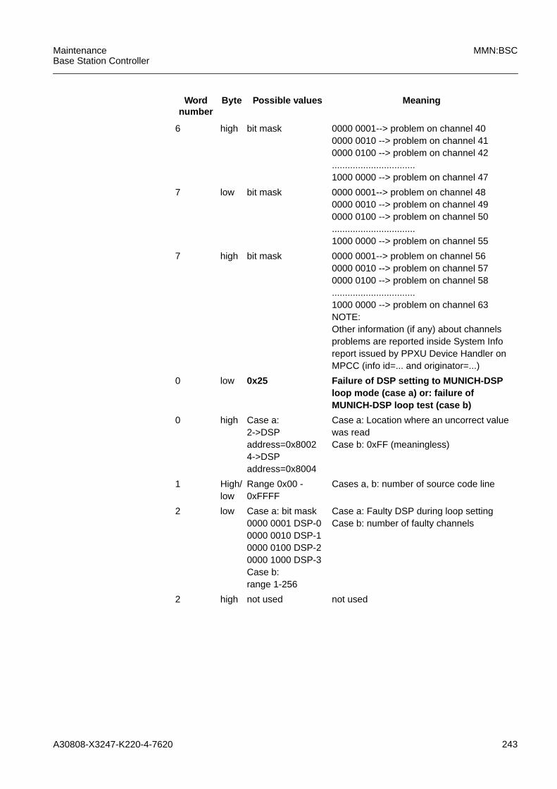
A30808-X3247-K220-4-7620 243
MaintenanceBase Station Controller
MMN:BSC
6 high bit mask 0000 0001--> problem on channel 400000 0010 --> problem on channel 410000 0100 --> problem on channel 42................................1000 0000 --> problem on channel 47
7 low bit mask 0000 0001--> problem on channel 480000 0010 --> problem on channel 490000 0100 --> problem on channel 50................................1000 0000 --> problem on channel 55
7 high bit mask 0000 0001--> problem on channel 560000 0010 --> problem on channel 570000 0100 --> problem on channel 58................................1000 0000 --> problem on channel 63NOTE:Other information (if any) about channelsproblems are reported inside System Inforeport issued by PPXU Device Handler onMPCC (info id=... and originator=...)
0 low 0x25 Failure of DSP setting to MUNICH-DSPloop mode (case a) or: failure ofMUNICH-DSP loop test (case b)
0 high Case a:2->DSPaddress=0x80024->DSPaddress=0x8004
Case a: Location where an uncorrect valuewas readCase b: 0xFF (meaningless)
1 High/low
Range 0x00 -0xFFFF
Cases a, b: number of source code line
2 low Case a: bit mask0000 0001 DSP-00000 0010 DSP-10000 0100 DSP-20000 1000 DSP-3Case b:range 1-256
Case a: Faulty DSP during loop settingCase b: number of faulty channels
2 high not used not used
Wordnumber
Byte Possible values Meaning
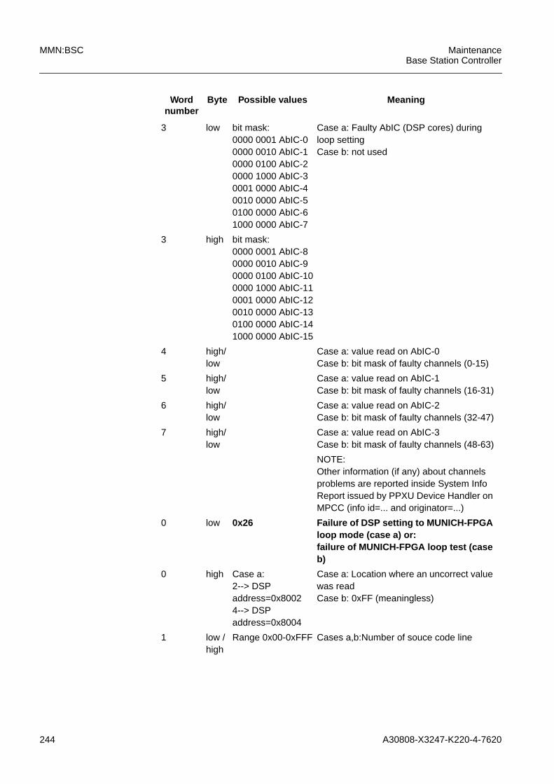
244 A30808-X3247-K220-4-7620
MMN:BSC MaintenanceBase Station Controller
3 low bit mask:0000 0001 AbIC-00000 0010 AbIC-10000 0100 AbIC-20000 1000 AbIC-30001 0000 AbIC-40010 0000 AbIC-50100 0000 AbIC-61000 0000 AbIC-7
Case a: Faulty AbIC (DSP cores) duringloop settingCase b: not used
3 high bit mask:0000 0001 AbIC-80000 0010 AbIC-90000 0100 AbIC-100000 1000 AbIC-110001 0000 AbIC-120010 0000 AbIC-130100 0000 AbIC-141000 0000 AbIC-15
4 high/low
Case a: value read on AbIC-0Case b: bit mask of faulty channels (0-15)
5 high/low
Case a: value read on AbIC-1Case b: bit mask of faulty channels (16-31)
6 high/low
Case a: value read on AbIC-2Case b: bit mask of faulty channels (32-47)
7 high/low
Case a: value read on AbIC-3Case b: bit mask of faulty channels (48-63)
NOTE:Other information (if any) about channelsproblems are reported inside System InfoReport issued by PPXU Device Handler onMPCC (info id=... and originator=...)
0 low 0x26 Failure of DSP setting to MUNICH-FPGAloop mode (case a) or:failure of MUNICH-FPGA loop test (caseb)
0 high Case a:2--> DSPaddress=0x80024--> DSPaddress=0x8004
Case a: Location where an uncorrect valuewas readCase b: 0xFF (meaningless)
1 low /high
Range 0x00-0xFFF Cases a,b:Number of souce code line
Wordnumber
Byte Possible values Meaning

A30808-X3247-K220-4-7620 245
MaintenanceBase Station Controller
MMN:BSC
possible specific problems (first add info in test report); see Tab. 5.10.
e) PPXU diag end phaseThe only role of this phase is to put the PPXU in service.
2 low Case a:Bit mask:0000 0001 DSP-00000 0010 DSP-10000 0100 DSP-20000 1000 DSP-3Case b:range 1-256
Case a: Faulty DSP during loop settingCase b: number of fauty channels
2 high not used not used
3 low Bit mask:0000 0001 AbIC-00000 0010 AbIC-10000 0100 AbIC-20000 1000 AbIC-30001 0000 AbIC-40010 0000 AbIC-50100 0000 AbIC-61000 0000 AbIC-7
Case a: Faulty AbIC (DSP cores) duringloop settingCase b: not used
3 high Bit mask:0000 0001 AbIC-80000 0010 AbIC-90000 0100 AbIC-100000 1000 AbIC-110001 0000 AbIC-120010 0000 AbIC-130100 0000 AbIC-141000 0000 AbIC-15
Case a: Faulty AbIC (DSP cores) duringloop settingCase b: not used
4 low /high
Case a: Value read on AbIC-0Case b: bit mask of faulty channels (0-7)
5 low /high
Case a: Value read on AbIC-1Case b: bit mask of faulty channels (8-15)
6 low /high
Case a: Value read on AbIC-2Case b: bit mask of faulty channels (16-23)
7 low /high
Case a: Value read on AbIC-3Case b: bit mask of faulty channels (24-31)
Wordnumber
Byte Possible values Meaning
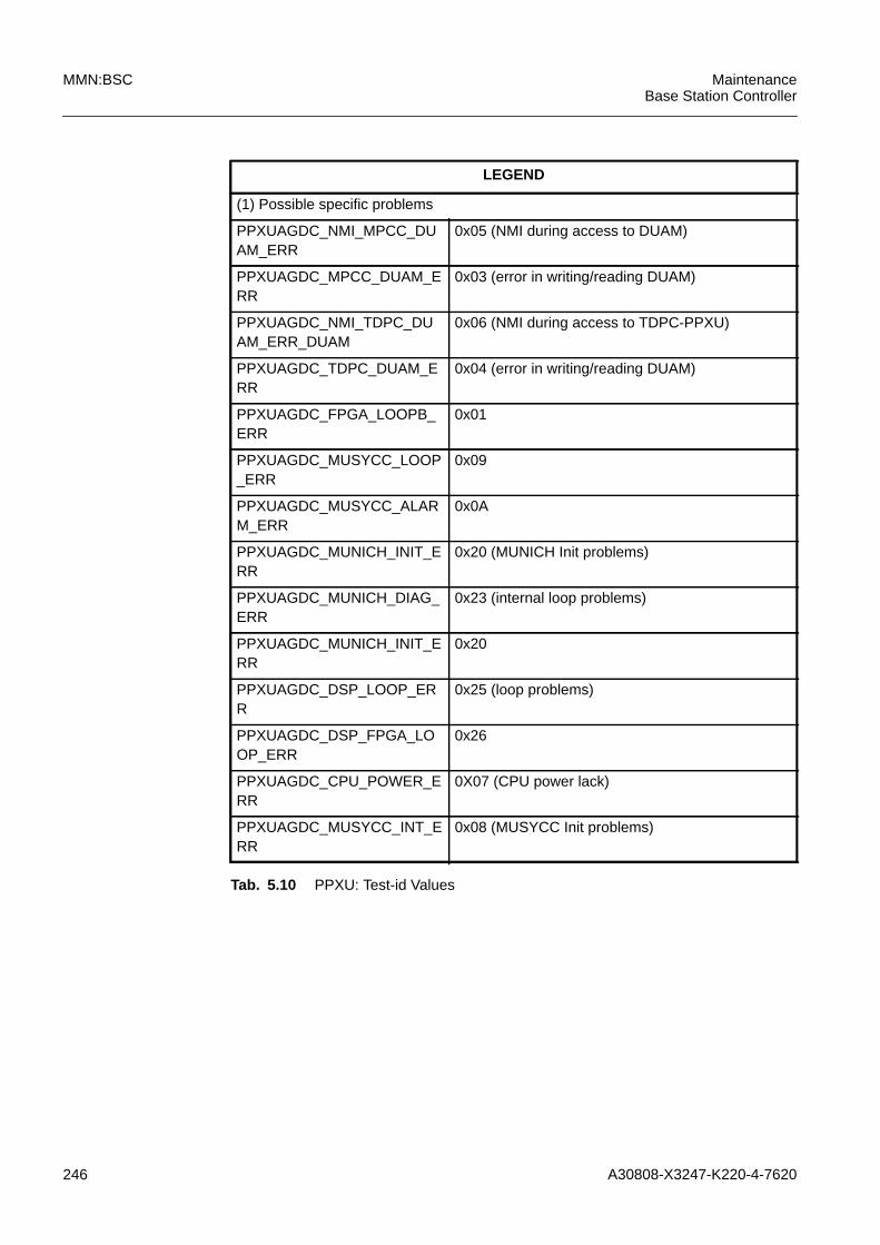
246 A30808-X3247-K220-4-7620
MMN:BSC MaintenanceBase Station Controller
LEGEND
(1) Possible specific problems
PPXUAGDC_NMI_MPCC_DUAM_ERR
0x05 (NMI during access to DUAM)
PPXUAGDC_MPCC_DUAM_ERR
0x03 (error in writing/reading DUAM)
PPXUAGDC_NMI_TDPC_DUAM_ERR_DUAM
0x06 (NMI during access to TDPC-PPXU)
PPXUAGDC_TDPC_DUAM_ERR
0x04 (error in writing/reading DUAM)
PPXUAGDC_FPGA_LOOPB_ERR
0x01
PPXUAGDC_MUSYCC_LOOP_ERR
0x09
PPXUAGDC_MUSYCC_ALARM_ERR
0x0A
PPXUAGDC_MUNICH_INIT_ERR
0x20 (MUNICH Init problems)
PPXUAGDC_MUNICH_DIAG_ERR
0x23 (internal loop problems)
PPXUAGDC_MUNICH_INIT_ERR
0x20
PPXUAGDC_DSP_LOOP_ERR
0x25 (loop problems)
PPXUAGDC_DSP_FPGA_LOOP_ERR
0x26
PPXUAGDC_CPU_POWER_ERR
0X07 (CPU power lack)
PPXUAGDC_MUSYCC_INT_ERR
0x08 (MUSYCC Init problems)
Tab. 5.10 PPXU: Test-id Values

A30808-X3247-K220-4-7620 247
MaintenanceBase Station Controller
MMN:BSC
5.5 NACK CAUSES
- unsuccessful wrong meid the objects addressed are not correct.- object not equipped the MOT is not created.- other tests running maximum number of tests are already queued
or running. No more tests are acceptable.- MOTS_NOT_LOCKED the MOT is not locked.
The following are the nack causes directly reported by DH:
- T_Resource_Currently_Busy- T_Invalid_Command_Parms- Unsuccessful_Ntv_Outage- Unsuccessful_Object_Notequipped- Unsuccessful_Invalid_Status- Unsuccessful_Power_Off- Unsuccessful_Other_Copy_Powered_Down

248 A30808-X3247-K220-4-7620
MMN:BSC MaintenanceBase Station Controller

A30808-X3247-K220-4-7620 249
MaintenanceBase Station Controller
MMN:BSC
6 AbbreviationsACTM ACT for the Base Rack/Shelter
BSS Base Station System
BTS Base Transceiver Station
BTSE Base Transceiver Station Equipment
DH Device Handler
DISK physic disk
DK40 Led Alarm Panel Control
DUKIT Duplex Combiner Kit
EMI Electro Magnetic Interference
ESD Electrostatic Sensitive Device
GSM Global System for Mobile Communications
HMOI Hardware Managed Object
HW Hard Ware
HW Hardware
ITMN Installation & Test Manual
IXLT Interface X.25 and Local Terminal Interface
LAPD Link Access Procedure on the D-Channel
LED Light Emitting Diode
LICD Line Card
LICDS Line Card Spare
LMT Local Maintenance Terminal
MEMT Memory of Telephone Processor
MOT Managed Object Under Test
MPCC Main Processor Control Circuit
N No
nob-RIU Not On Board Remote Inventory Unit
NTW Network
ob_RIU On Board Remote Inventory Unit
OMC Operation and Maintenance Center
OS Operating System
PCM Pulse Code Modulation
PLLH Phase Locked Loop Oscillator High Perfor-mance
PLMN Public Land Mobile Network
PPCC Peripheral Processor Common Channel
PPCU Peripheral packet Control Unit
PPLD Peripheral Processor LAPD
PPXL Peripheral processor LAPD/SS7
PPXU Peripheral processor used at PPCU evolu-tion
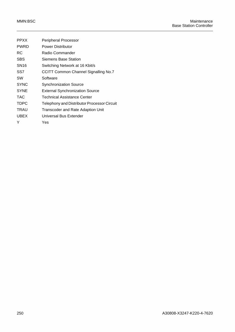
250 A30808-X3247-K220-4-7620
MMN:BSC MaintenanceBase Station Controller
PPXX Peripheral Processor
PWRD Power Distributor
RC Radio Commander
SBS Siemens Base Station
SN16 Switching Network at 16 Kbit/s
SS7 CCITT Common Channel Signalling No.7
SW Software
SYNC Synchronization Source
SYNE External Synchronization Source
TAC Technical Assistance Center
TDPC Telephony and Distributor Processor Circuit
TRAU Transcoder and Rate Adaption Unit
UBEX Universal Bus Extender
Y Yes


