Embed Size (px)
Citation preview

1
BSPlace: A BLE Swapping technique for placement
04.09.2014
Minsik Hong
George Hwang
Hemayamini Kurra
Minjun Seo

2
BSPlace: A BLE Swapping technique for placement
• BLE Level Swapping within Simulated Annealing• Chen, Gang, and Jason Cong. "Simultaneous timing driven cluster-
ing and placement for FPGAs." Field Programmable Logic and Ap-plication. Springer Berlin Heidelberg, 2004. 158-167.
• Use Rent’s rule to determine swapping method• Singh, Amit, Ganapathy Parthasarathy, and Malgorzata Marek-
Sadowska. "Efficient circuit clustering for area and power reduction in FPGAs." ACM Transactions on Design Automation of Electronic Systems (TODAES) 7.4 (2002): 643-663.

3
Outline• iRAC
• Clustering Comparison• Rent’s Rule• Key terms• Clustering Step• Results
• SCPlace• Introduction
4
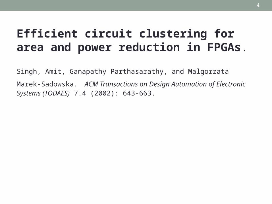
Efficient circuit clustering for area and power reduction in FPGAs.
Singh, Amit, Ganapathy Parthasarathy, and Malgorzata Marek-Sadowska. ACM Transactions on Design Automation of Electronic Systems (TODAES) 7.4 (2002): 643-663.

5
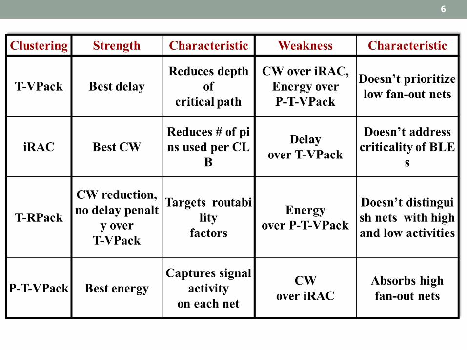
Clustering Comparison• TVPACK• What is different in RPACK?
• Gain functions for considering routing constraints in cost function while clustering
• RPACK + ----- iRAC• Rent’s rule to depopulate the clusters!! Best CW
6

7
Rent’s Rule•
• Where Nio is the number of inputs and outputs in a CLB
• K is the average number of connections per BLE• Calculate k in technology mapping phase
• B is the number of BLEs in a CLB• P is the rent’s parameter
• Since FPGA has uniform interconnect resources, p at local level is as-sumed to be uniform
• Characterize the complexity of a cluster• Smaller values of p mean that the cluster’s external routing re-
quirement is low• So, a good clustering solution will ensure that the Rent’s parameter
of the generated cluster is small.
)log()log()log( , BpkNkBN ioP
io

8
Net Length : Local Rent’s parameter Pld
• Complexity Varies across design.
• Solution – Use local interconnect complexity measure based in interconnect length distributions. (Van Marck et al.,95)
• Reduces to Rent’s exponent for uniform design at the top level

9
Net Length : Rent’s Parameter• Van Marck, Stroobandt, Campenhout, 1995
• p =D(log Ni) / D(log Li)• p – Rent’s parameter• Li - length of a net
• Ni - number of nets of length Li
• First Order Approximation for varying rent’s parameter• Connects net-length with Rent’s parameter!
• Wirelength, channel width, routability estimation based on Rent’s parameter

10
Applications of Rent’s Rule• layout parameter estimations in Electronic Design Auto-
mation, • studies of new computer architectures, and • the generation of synthetic circuit benchmarks.

11
Applications of Rent’s Rule• The increasing problem sizes in electronic design and the
sub-micron design challenges have placed the need for a priori estimates of chip layout parameters in the forefront.• The generality and predictive power of Rent’s rule are perfect for
such estimates.
• Another application of Rent’s rule tries to assess the merits of new chip or computer architectures before they have to be built, using wire length estimates based on Rent’s rule and a generic model for the architecture. This research has gained attention especially due to the possibilities of using optical interconnections to build three-dimensional chips

12
Key terms• Degree of an BLE
• the number of nets incident to that BLE
• Separation of an BLE• The sum of all terminals of nets incident to the BLE
• Connectivity factor (c)
• Weight, w(e)
2deg ree
separationc
net on the terminalsofnumber theisr where,2
)(r
ew

13
Clustering step (1)• First, calculate the connectivity factor of all unclustered BLEs.
BLENET
Terminal Cluster

14
Clustering step (1)• First, calculate the c factor of all unclustered BLEs.
Degree - the number of nets incident to BLE A
1
2
3
4

15
Clustering step (1)
1 2 3
4 5 6
7 8 9
10 11 12 13
14
• First, calculate the c factor of all unclustered BLEs.
Degree - the number of nets incident to BLE ASeparation - the sum of all terminals of nets incident to the BLE A
125.116
18
4
18
deg 22
ree
separationc
1516
17
18

16
Clustering step (2)
• Second, choose a seed
Degree = 4, c=1.125
Degree = 4, c=0.5
Cluster size = 5
which has highest degree and lowest c
17
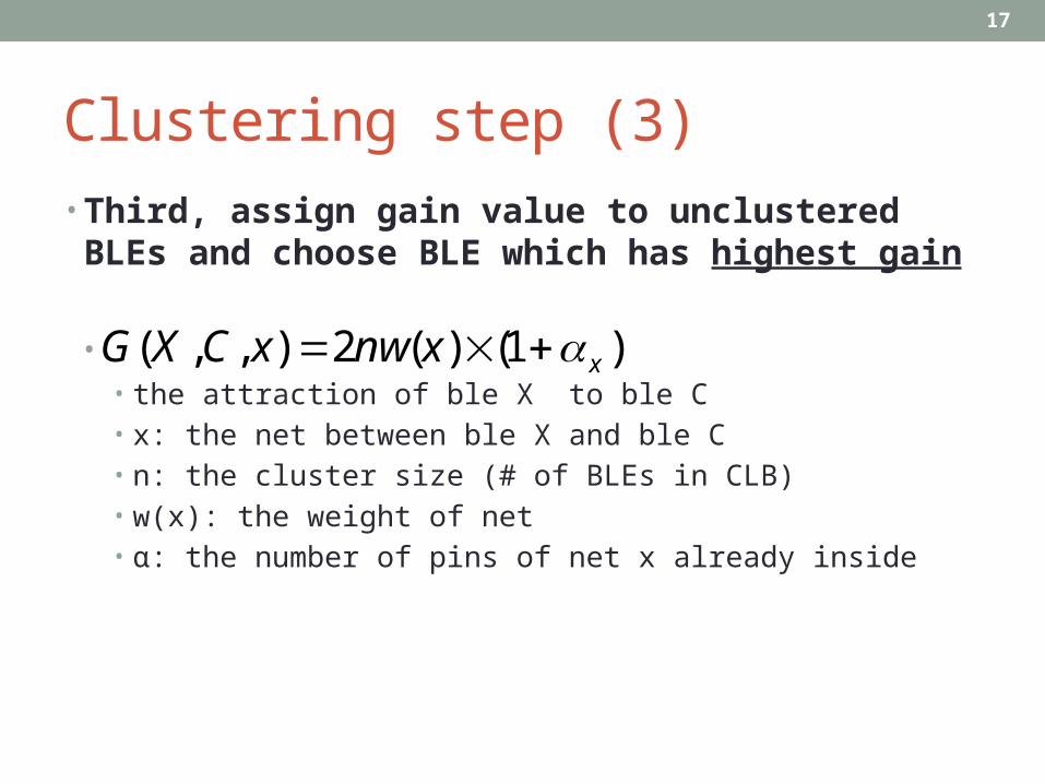
Clustering step (3)• Third, assign gain value to unclustered BLEs and
choose BLE which has highest gain
)1()(2),,( xxnwxCXG • • the attraction of ble X to ble C• x: the net between ble X and ble C• n: the cluster size (# of BLEs in CLB)• w(x): the weight of net• α: the number of pins of net x already inside

18
Clustering step (3)
16)11(2
242)( XG
)1()(2),,( xxnwxCXG
Cluster size = 4
net on the terminalsofnumber theisr where,2
)(r
ew
n: the cluster size (# of BLEs in CLB)α: the number of pins of net x already inside
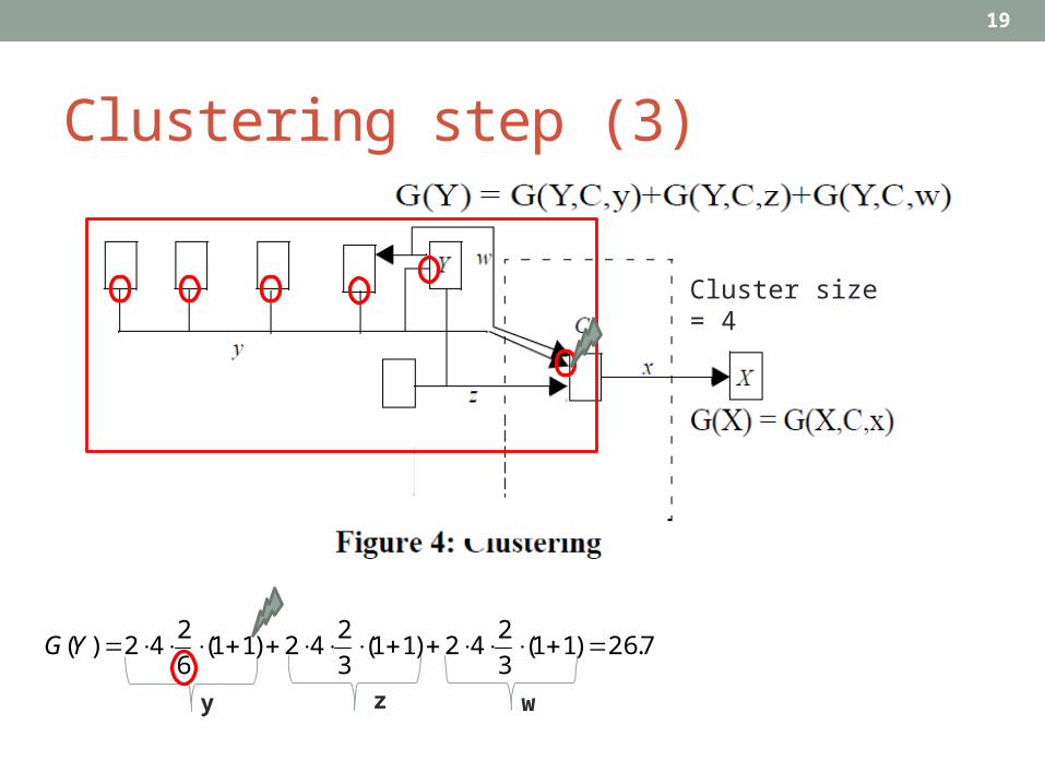
19
Clustering step (3)
7.26)11(3
242)11(
3
242)11(
6
242)( YG
y z w
Cluster size = 4

20
Clustering step (3)
16)11(2
242)( XG
7.26)11(3
242)11(
3
242)11(
6
242)( YG
16016)( kXG
If adding X to C fully absorbs net x, then G(X,C,x) is multiplied by a large constant value k. (ex. k=10)
Cluster size = 4
choose BLE which has highest gain
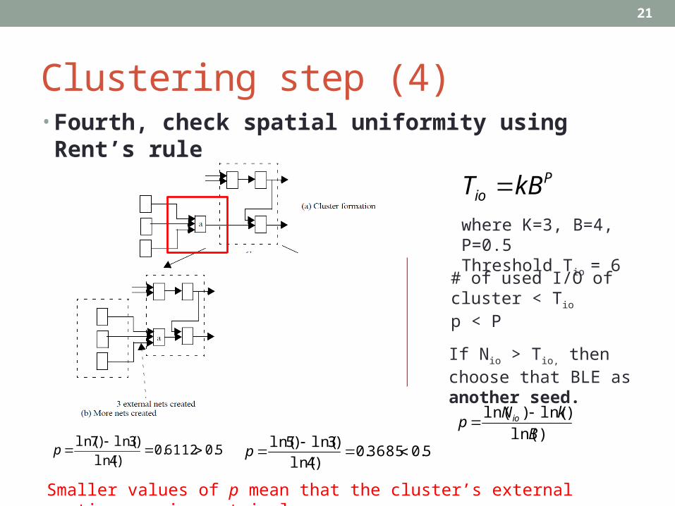
21
Clustering step (4)• Fourth, check spatial uniformity using Rent’s rule
Pio kBT
where K=3, B=4, P=0.5Threshold Tio = 6
If Nio > Tio, then choose that BLE as another seed.
)ln(
)ln()ln(
B
kNp io
5.06112.0)4ln(
)3ln()7ln(
p 5.03685.0
)4ln(
)3ln()5ln(
p
# of used I/O of cluster < Tio p < P
Smaller values of p mean that the cluster’s external routing requirement is low

22
Results(1)
• Random Seed of RPack
• iRAC is more effective in clustering circuits which have a higher percent-age of low-fanout nets.
• Why?

23
Result(2)
iRAC is able to lower the number of external nets, and the Rent’s parameter of the circuits after clustering!

24
Simultaneous timing driven clustering and placement for FPGAs.
Chen, Gang, and Jason Cong. Field Programmable Logic and Application. Springer Berlin Heidelberg, 2004. 158-167.

25
Why simultaneous placement and clustering?

26
Why simultaneous placement and clustering?
• More freedom of changing to change a circuit structure but fast and accurate estimation of wirelength, timing and routability are not available in clustering stage
• In placement stage due to the fixed circuit structure, si-multaneous optimization of wirelength, timing and routabil-ity are possible.
• Sub-optimal place and route result!!!!

27
Key concept• Fragment level move
• BLE to a new CLB• Check for valid CLB configuration• Feasibility (number of BLEs and input pins)• Update the cost function
• Block level move• CLB to CLB
• Logic duplication

28
To be Continued….