Embed Size (px)
Citation preview
Installation and Operation Guide
Boost Timer
BST3
PRO

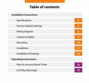
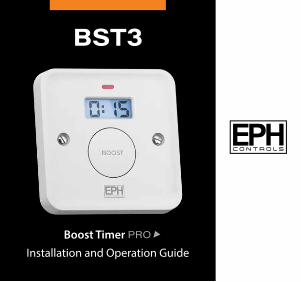
Table of contents
4
5
6
8
10
11
12
14
LCD Blue Back-light
Factory Default Settings
Specifications
Wiring Diagram
Caution & Safety
Mounting
Installation
Installation Drawings
How to use your Boost Timer
Installation Instructions
Operating Instructions
15
4 BST3
SpecificationsPower supply: 230Vac 50 Hz
Contact Rating: 250Vac 13A Resistive up to 3kW
1000W filament or halogen lighting
500W fluorescent lighting
100W LED lighting
Ambient Temperature: 0...45˚C
Classification: Type 1A Action (RL1)
Pollution degree: Degree 2
IP rating: IP20
Rated Impulse voltage: Resistance to voltage surge 2500V as per EN60730
Recommended 16A RCBO or 16A MCB & 100mA Power protection: RCD where applicable
Boost Period: 15 / 30 min / 1 hr / 2 hrs / 3 hrs
5Boost Timer Pro 5Boost Timer Pro
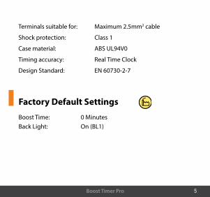
Terminals suitable for: Maximum 2.5mm2 cable
Shock protection: Class 1
Case material: ABS UL94V0
Timing accuracy: Real Time Clock
Design Standard: EN 60730-2-7
Factory Default Settings
Boost Time: 0 MinutesBack Light: On (BL1)
6 BST3
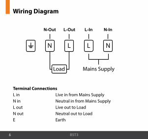
Wiring Diagram
Terminal ConnectionsL in Live in from Mains SupplyN in Neutral in from Mains Supply L out Live out to LoadN out Neutral out to LoadE Earth
N-Out L-Out L-In N-In
NN L L
Load Mains Supply
7Boost Timer Pro 7Boost Timer Pro
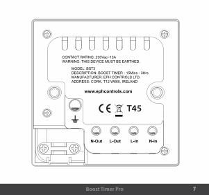
N-Out L-Out L-In N-In
MODEL: BST3 DESCRIPTION: BOOST TIMER - 15Mins - 3HrsMANUFACTURER: EPH CONTROLS LTD.ADDRESS: CORK, T12 W665, IRELAND
CONTACT RATING: 230Vac~13AWARNING: THIS DEVICE MUST BE EARTHED.
www.ephcontrols.com
4

8 BST3
Caution! � Installation and connection should only be carried out by a
qualified person.
� Only qualified electricians or service engineers are permitted to open the Boost Timer.
� If the Boost Timer is used in a way not specified by the manufacturer, its safety may be impaired.
� Prior to setting the Boost Timer, it is necessary to complete all required settings described in the section.
� Provision must be made in the fixed wiring to incorporate a minimum 3mm contact separation in both poles of the supply.
9Boost Timer Pro
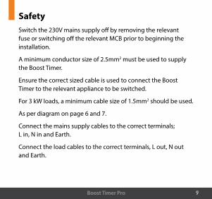
SafetySwitch the 230V mains supply off by removing the relevant fuse or switching off the relevant MCB prior to beginning the installation.
A minimum conductor size of 2.5mm2 must be used to supply the Boost Timer.
Ensure the correct sized cable is used to connect the Boost Timer to the relevant appliance to be switched.
For 3 kW loads, a minimum cable size of 1.5mm2 should be used.
As per diagram on page 6 and 7.
Connect the mains supply cables to the correct terminals; L in, N in and Earth.
Connect the load cables to the correct terminals, L out, N out and Earth.
10 BST3
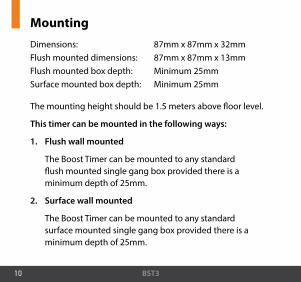
MountingDimensions: 87mm x 87mm x 32mmFlush mounted dimensions: 87mm x 87mm x 13mmFlush mounted box depth: Minimum 25mmSurface mounted box depth: Minimum 25mm
The mounting height should be 1.5 meters above floor level.
This timer can be mounted in the following ways:
1. Flush wall mounted
The Boost Timer can be mounted to any standard flush mounted single gang box provided there is a minimum depth of 25mm.
2. Surface wall mounted
The Boost Timer can be mounted to any standard surface mounted single gang box provided there is a minimum depth of 25mm.
11Boost Timer Pro
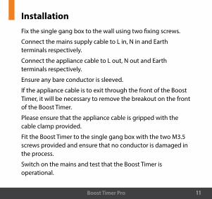
InstallationFix the single gang box to the wall using two fixing screws.
Connect the mains supply cable to L in, N in and Earth terminals respectively.
Connect the appliance cable to L out, N out and Earth terminals respectively.
Ensure any bare conductor is sleeved.
If the appliance cable is to exit through the front of the Boost Timer, it will be necessary to remove the breakout on the front of the Boost Timer.
Please ensure that the appliance cable is gripped with the cable clamp provided.
Fit the Boost Timer to the single gang box with the two M3.5 screws provided and ensure that no conductor is damaged in the process.
Switch on the mains and test that the Boost Timer is operational.
12 BST3
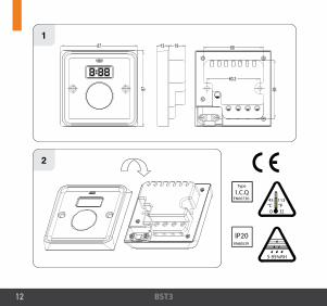
187
87
13 19 68
69
60,3
2
13Boost Timer Pro 13Boost Timer Pro
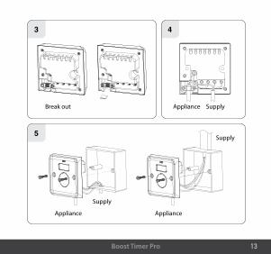
3 4
5
Break out Appliance Supply
Appliance
Supply
Appliance
Supply
14 BST3
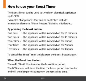
How to use your Boost TimerThe Boost Timer can be used to switch on electrical appliances up to 3kW.Examples of appliances that can be controlled include: Immersion elements / Panel heaters / Lighting / Boilers etc.
By pressing the boost button:One time - the appliance will be switched on for 15 minutes.Two times - the appliance will be switched on for 30 minutes.Three times - the appliance will be switched on for 1 hour.Four times - the appliance will be switched on for 2 hours.Five times - the appliance will be switched on for 3 hours.
To cancel the Boost Timer, simply press the Boost button again.
When the Boost is activated:The red LED will illuminate for the boost time period.The LCD screen will show the time the boost period is active for and will then begin to countdown the remaining time.

15Boost Timer Pro
LCD Blue BacklightThere are two options available on the Boost Timer.
To choose between having the blue backlight On or Off, simply press and hold the Boost button for 5 seconds.
BL1 – Blue Backlight On
BL0 – Blue Backlight Off
BL1 – The LCD blue backlight will illuminate for the duration of the boost time period.
BL0 – The LCD blue backlight will only illuminate for the first 5 seconds of the boost time period.
On BL1

EPH Controls IE
EPH Controls UK
© 2
020
EPH
Con
trol
s Lt
d.
[email protected] +44 1933 626 396F +44 1933 626 218
2020
0522
_BST
3_G
uide
[email protected] +353 21 434 6238F +353 21 454 5890