Embed Size (px)
Citation preview
November 2014 Edition 1 BT4560A981-00 14-11H
BATTERYIMPEDANCE METER
BT4560
Instruction Manual

i
4 Customization of Measurement Conditions 37
4.1 Setting the Measurement Starting Conditions (Trigger Functions) ....................................... 37
Setting the trigger .......................................37 Inputting the external trigger .......................38
4.2 Starting the Measurement After the Response of the Measuring Object is Stable (Sample Delay Function) ......................................... 38
4.3 Maintaining Voltage Measurement Accuracy (Self-Calibration Function) ..................... 41
4.4 Stabilizing the Measurement Values (Average Function) ............ 42
4.5 Compensating the Potential Slope Due to Electric Discharge (Slope Correction Function) .......... 43
4.6 Preventing the Overcharge due to Measurement Signal (Voltage Limit Function) ............................... 45
4.7 Prevents Charging and Discharging due to the Measurement Signal (Measurement Signal Zero Cross Stop Function) ..................... 47
5 Judging Measurement Results (Comparator Function) 49
5.1 Turning the Comparator Function ON and OFF .................... 50
5.2 Setting the Upper and Lower Limit Value ...................................... 51
5.3 Voltage is Judged with the Absolute Value ............................... 54
5.4 Checking the Judgment with Sound .............................................. 55
5.5 Checking the Judgment Result .... 56
Contents
Introduction ................................................ 1 Registered trademark ...................................1
Verifying Package Contents ..................... 1Safety Information ..................................... 3Operating Precautions .............................. 6
1 Overview 111.1 Product Overview and Features ....111.2 Names and Functions of Parts ..... 121.3 Screen Confi guration and
Operation ........................................ 15 Measurement screen ..................................15 Settings screen ...........................................15
1.4 Measurement Flow ......................... 16
2 Preparation 172.1 Connecting the Power Cord .......... 172.2 Connecting the Measurement
Probe and Temperature Sensor (Optional) ........................................ 18
Connect the four-terminal cable to the instrument ...................................................18
Connect the temperature sensor to the instrument ...................................................18
2.3 Turning the Power ON or OFF ....... 192.4 Inspection Before Use ................... 19
3 Basic Measurement 213.1 Selecting the Measurement
Functions ........................................ 213.2 Selecting the Measurement Range 223.3 Setting the Measurement Speed ... 233.4 Setting the Measurement
Frequency ....................................... 24 When the measurement time is long
(Display of the Progress Bar) ......................253.5 Performing the Zero Adjustment .. 26
Performing the zero adjustment ..................26 Connection when performing the zero
adjustment ..................................................293.6 Checking the Measurement
Results ............................................ 30 Detecting the measurement abnormality ....30 Temperature measurement indication ........32 Overrange indication ...................................32
3.7 Basic Measurement Examples ...... 33
10
9
8
7
6
5
4
3
2
1
Appx.
Index
Contents
ii
9 Communication (RS-232C, USB) 95
9.1 Features of Interface ...................... 95 Specifi cations ..............................................95
9.2 Connecting and Setting Method ... 96 Using the USB interface .............................96 Using the RS-232C cable ...........................98 Setting the transmission speed
(Common for USB, RS-232C) ....................999.3 Controlling the Communication
and Acquiring the Data ................ 100 Remote state/Local state ..........................100
10 Specifi cations 10110.1 Specifi cations of Measurement
Functions ...................................... 10110.2 Additional Function ..................... 10410.3 User Interface ................................11010.4 External Interface ..........................11010.5 Accuracy ........................................11210.6 General Specifi cations .................115
Standards ................................................. 116 Accessories .............................................. 116 Options ..................................................... 116
11 Maintenance and Service 117
11.1 Troubleshooting ............................117 Q&A (Frequent inquiries) .......................... 117 Error display and remedy ..........................121
11.2 Inspection, Repair and Cleaning 12311.3 Discarding the Instrument ........... 124
Lithium battery removal ............................124
6 Saving and Reading Measurement Conditions 57
6.1 Saving the Setting Conditions (Panel Saving Function) ................ 58
6.2 Reading the Setting Conditions (Panel Loading Function) .............. 60
6.3 Deleting the Contents of the Panel 61
7 System Setting 637.1 Making the Key Operation
Effective or Ineffective ................... 637.2 Setting the Sound of the Key
Operation Effective or Ineffective . 657.3 Adjusting the Contrast of the
Screen ............................................. 667.4 Adjusting the Backlight ................. 677.5 System Testing ............................... 687.6 Confi rm Instrument Information ... 737.7 Initializing (Reset) .......................... 74
Initial setting table .......................................76
8 External control (EXT.I/O) 79
8.1 External Input/output Terminals and Signals ..................................... 80
Switching the current sink (NPN) /the current source (PNP) ..................................80
Arranging the usage connector and the signals .........................................................80
Functions of each signal .............................828.2 Timing Chart ................................... 84
Acquiring the judgment results after starting measurement .................................84
Timing of the zero adjustment.....................87 Timing of the self-calibration .......................87 Timing of the panel loading .........................89 Output signal status when turning ON
the power supply .........................................89 Taking-in fl ow with the external trigger ........90
8.3 Internal Circuitry ............................ 91 Electrical Specifi cations ..............................92 Examples of connection ..............................93
8.4 Checking the External Control ...... 94 Testing the inputs/outputs (EXT.I/O
testing functions) .........................................94
Contents
iii
Appendix A1Appx. 1 Measurement
Parameters and Calculation Formula ................A1
Appx. 2 Four-terminal Pair Method ......A2Appx. 3 Cautions When Making
Your Own Measurement Probe .........................................A4
Appx. 4 Measurement Probe Structure and Extension .........A6
Appx. 5 Measurement Value in the Four-terminal Measurement (Difference in Measurement Value Due to the Measurement Probe) ....A7
Appx. 6 Infl uence of the Eddy Current A8Appx. 7 Zero Adjustment ......................A8Appx. 8 Measurement Probe (Option) A12Appx. 9 Precautions When
Making the Switching Unit ....A13Appx. 10 Precautions When
Measuring the Battery ...........A15Appx. 11 Calibrating the Instrument ....A18Appx. 12 Rack Mounting .......................A20Appx. 13 Dimensional Diagram ............A22
Index Index1
10
9
8
7
6
5
4
3
2
1
Appx.
Index

Contents
iv
1
Introduction
Introduction Thank you for purchasing the HIOKI BT4560 Battery Impedance Meter. To obtain maximum performance from the instrument, please read this manual fi rst, and keep it handy for future reference.
Registered trademark
Microsoft and Windows are either registered trademarks or trademarks of Microsoft Corporation in the United States and other countries.
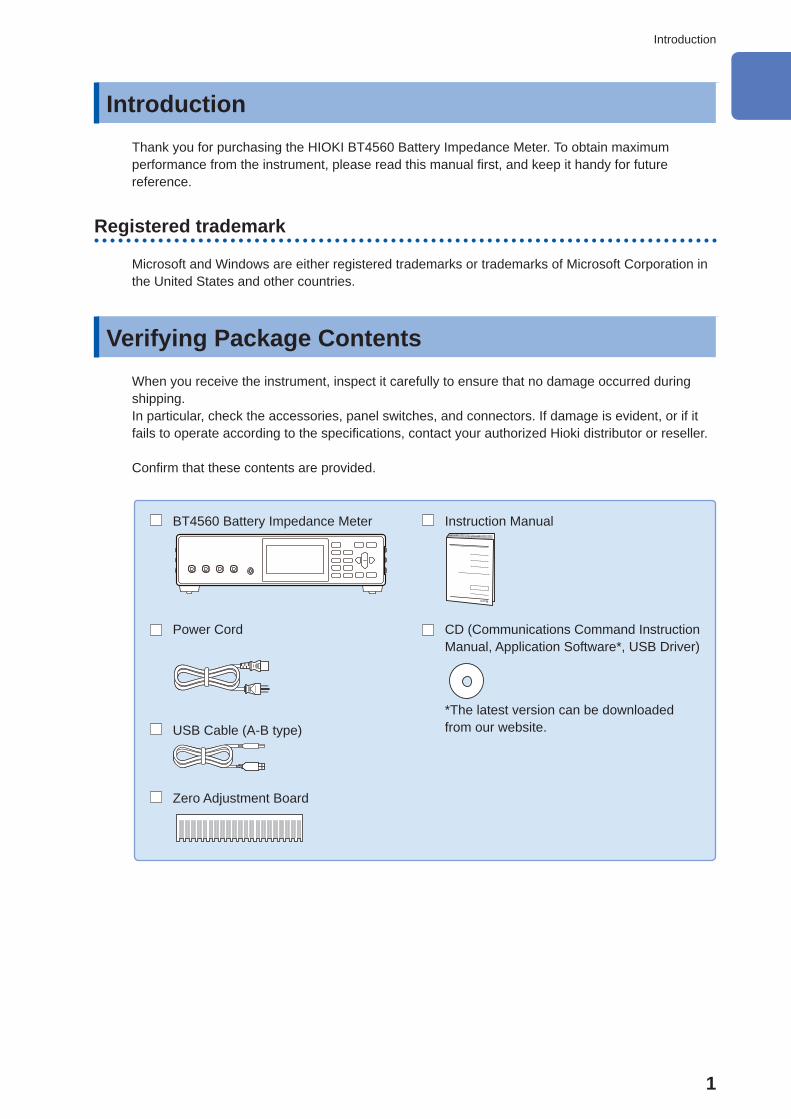
Verifying Package Contents When you receive the instrument, inspect it carefully to ensure that no damage occurred during shipping.In particular, check the accessories, panel switches, and connectors. If damage is evident, or if it fails to operate according to the specifi cations, contact your authorized Hioki distributor or reseller.
Confi rm that these contents are provided.
BT4560 Battery Impedance Meter Instruction Manual
Power Cord CD (Communications Command Instruction Manual, Application Software*, USB Driver)
* The latest version can be downloaded from our website.USB Cable (A-B type)
Zero Adjustment Board
10
9
8
7
6
5
4
3
2
1
Appx.
Ind.
2
Verifying Package Contents
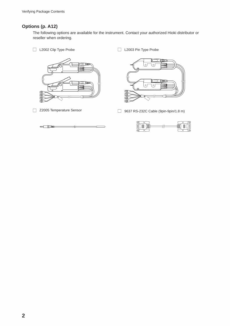
Options (p. A12)The following options are available for the instrument. Contact your authorized Hioki distributor or reseller when ordering.
L2002 Clip Type Probe L2003 Pin Type Probe
Z2005 Temperature Sensor 9637 RS-232C Cable (9pin-9pin/1.8 m)
3
Safety Information
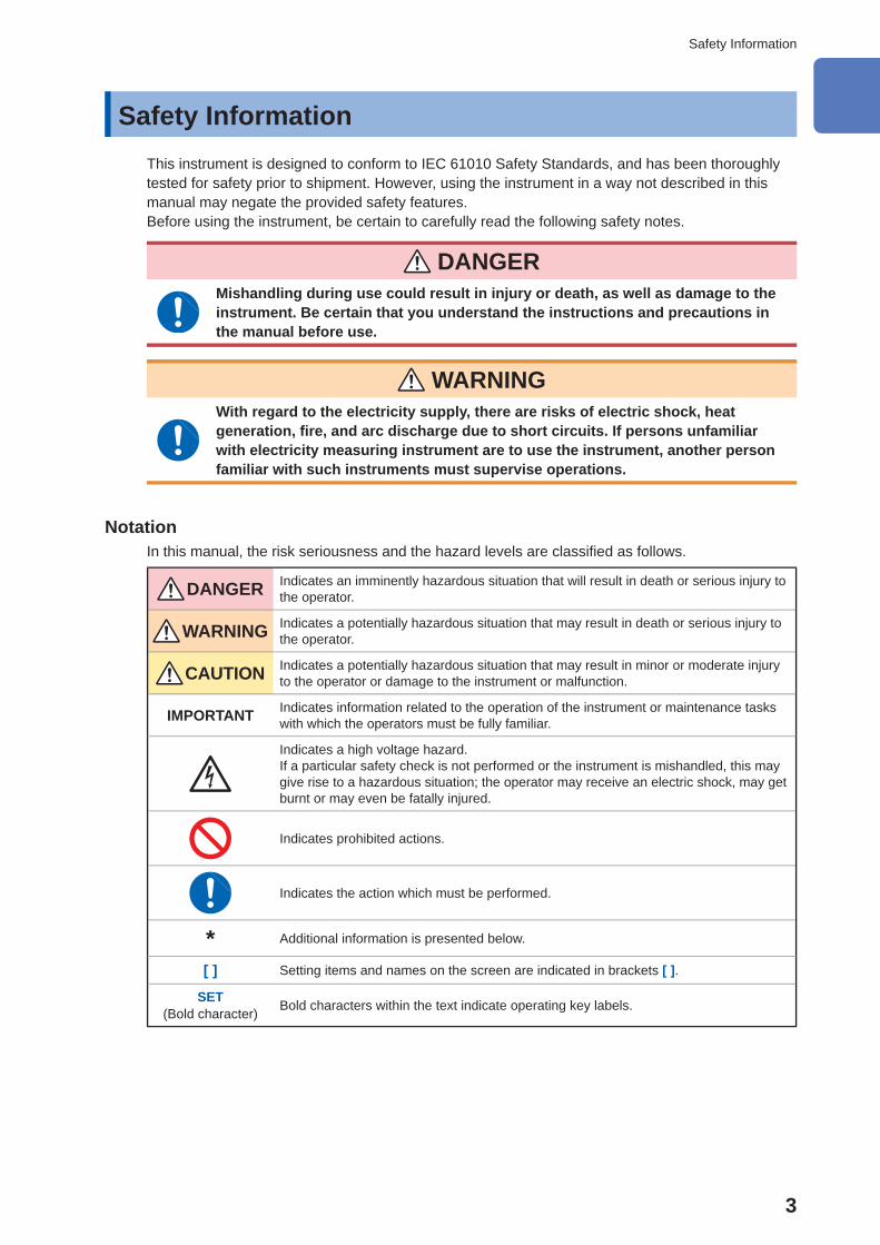
Safety Information This instrument is designed to conform to IEC 61010 Safety Standards, and has been thoroughly tested for safety prior to shipment. However, using the instrument in a way not described in this manual may negate the provided safety features.Before using the instrument, be certain to carefully read the following safety notes.
DANGERMishandling during use could result in injury or death, as well as damage to the instrument. Be certain that you understand the instructions and precautions in the manual before use.
WARNING With regard to the electricity supply, there are risks of electric shock, heat generation, fi re, and arc discharge due to short circuits. If persons unfamiliar with electricity measuring instrument are to use the instrument, another person familiar with such instruments must supervise operations.
NotationIn this manual, the risk seriousness and the hazard levels are classifi ed as follows.
DANGER Indicates an imminently hazardous situation that will result in death or serious injury to the operator.
WARNING Indicates a potentially hazardous situation that may result in death or serious injury to the operator.
CAUTION Indicates a potentially hazardous situation that may result in minor or moderate injury to the operator or damage to the instrument or malfunction.
IMPORTANT Indicates information related to the operation of the instrument or maintenance tasks with which the operators must be fully familiar.
Indicates a high voltage hazard.If a particular safety check is not performed or the instrument is mishandled, this may give rise to a hazardous situation; the operator may receive an electric shock, may get burnt or may even be fatally injured.
Indicates prohibited actions.
Indicates the action which must be performed.
* Additional information is presented below.
[ ] Setting items and names on the screen are indicated in brackets [ ].
SET(Bold character) Bold characters within the text indicate operating key labels.
10
9
8
7
6
5
4
3
2
1
Appx.
Ind.
4
Safety Information
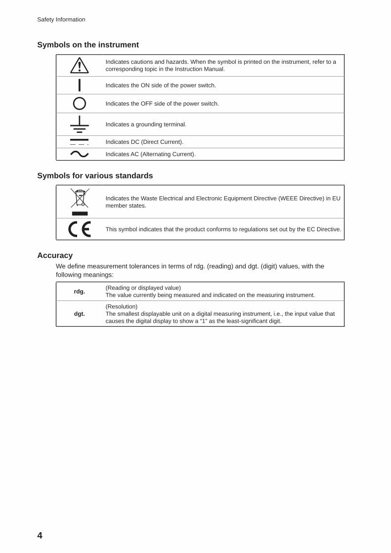
Symbols on the instrument
Indicates cautions and hazards. When the symbol is printed on the instrument, refer to a corresponding topic in the Instruction Manual.
Indicates the ON side of the power switch.
Indicates the OFF side of the power switch.
Indicates a grounding terminal.
Indicates DC (Direct Current).
Indicates AC (Alternating Current).
Symbols for various standards
Indicates the Waste Electrical and Electronic Equipment Directive (WEEE Directive) in EU member states.
This symbol indicates that the product conforms to regulations set out by the EC Directive.
AccuracyWe defi ne measurement tolerances in terms of rdg. (reading) and dgt. (digit) values, with the following meanings:
rdg. (Reading or displayed value)The value currently being measured and indicated on the measuring instrument.
dgt.(Resolution)The smallest displayable unit on a digital measuring instrument, i.e., the input value that causes the digital display to show a “1” as the least-signifi cant digit.
5
Safety Information
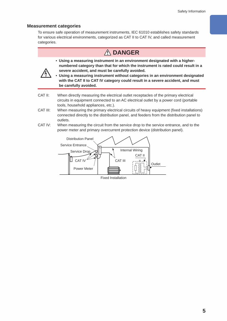
Measurement categoriesTo ensure safe operation of measurement instruments, IEC 61010 establishes safety standards for various electrical environments, categorized as CAT II to CAT IV, and called measurement categories.
DANGER • Using a measuring instrument in an environment designated with a higher-numbered category than that for which the instrument is rated could result in a severe accident, and must be carefully avoided.
• Using a measuring instrument without categories in an environment designated with the CAT II to CAT IV category could result in a severe accident, and must be carefully avoided.
CAT II: When directly measuring the electrical outlet receptacles of the primary electrical circuits in equipment connected to an AC electrical outlet by a power cord (portable tools, household appliances, etc.).
CAT III: When measuring the primary electrical circuits of heavy equipment (fi xed installations) connected directly to the distribution panel, and feeders from the distribution panel to outlets.
CAT IV: When measuring the circuit from the service drop to the service entrance, and to the power meter and primary overcurrent protection device (distribution panel).
Outlet
CAT IIInternal Wiring
Distribution Panel
Service Entrance
Service Drop
CAT IV
Power Meter
CAT III
Fixed Installation
10
9
8
7
6
5
4
3
2
1
Appx.
Ind.
6
Operating Precautions
Operating Precautions Follow these precautions to ensure safe operation and to obtain the full benefi ts of the various functions.
DANGERThis instrument carries a maximum electric current up to 1.5 A to the measuring object. Do not measure the primary battery. Doing so may cause damage to the measuring object.
Battery may cause ignition and damage due to overcharge/over discharge. Be certain in managing battery voltage when measuring.
WARNING If the measurement probe or the instrument is damaged, there is a risk of electric shock. Before using the instrument, perform the following inspection. • Before using the instrument, check that the coating of the measurement probes are neither ripped nor torn and that no metal parts of connection cord are exposed. Using the instrument under such conditions could result in electrocution. Replace the measurement probes with those specifi ed by our company.
• Before using the instrument for the fi rst time, verify that it operates normally to ensure that no damage occurred during storage or shipping. If you fi nd any damage, contact your authorized Hioki distributor or reseller.
Instrument installationInstalling the instrument in inappropriate locations may cause a malfunction of instrument or may give rise to an accident. Avoid the following locations.For details on the operating temperature and humidity, see the specifi cations p. 115.
WARNING • Exposed to direct sunlight or high temperature • Exposed to corrosive or combustible gases • Exposed to water, oil, chemicals, or solvents • Exposed to high humidity or condensation • Exposed to a strong electromagnetic fi eld or electrostatic charge • Exposed to high quantities of dust particles • Near induction heating systems (such as high-frequency induction heating systems and IH cooking equipment)
• Susceptible to vibration
7
Operating Precautions
Installation
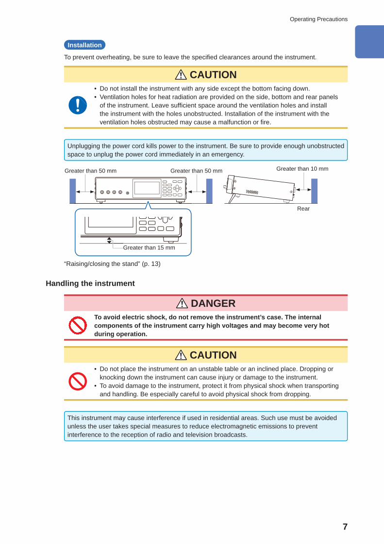
To prevent overheating, be sure to leave the specifi ed clearances around the instrument.
CAUTION • Do not install the instrument with any side except the bottom facing down. • Ventilation holes for heat radiation are provided on the side, bottom and rear panels of the instrument. Leave suffi cient space around the ventilation holes and install the instrument with the holes unobstructed. Installation of the instrument with the ventilation holes obstructed may cause a malfunction or fi re.
Unplugging the power cord kills power to the instrument. Be sure to provide enough unobstructed space to unplug the power cord immediately in an emergency.
Greater than 10 mm
Rear
Greater than 50 mmGreater than 50 mm
Greater than 15 mm
“Raising/closing the stand” (p. 13)
Handling the instrument
DANGER To avoid electric shock, do not remove the instrument’s case. The internal components of the instrument carry high voltages and may become very hot during operation.
CAUTION • Do not place the instrument on an unstable table or an inclined place. Dropping or knocking down the instrument can cause injury or damage to the instrument.
• To avoid damage to the instrument, protect it from physical shock when transporting and handling. Be especially careful to avoid physical shock from dropping.
This instrument may cause interference if used in residential areas. Such use must be avoided unless the user takes special measures to reduce electromagnetic emissions to prevent interference to the reception of radio and television broadcasts.
10
9
8
7
6
5
4
3
2
1
Appx.
Ind.
8
Operating Precautions
Before connecting the power cord
WARNING • Before turning the instrument on, make sure the supply voltage matches that indicated on its power connector. Connection to an improper supply voltage may damage the instrument and present an electrical hazard.
• To avoid electrical accidents and to maintain the safety specifi cations of this instrument, connect the power cord provided only to a 3-contact (two-conductor + ground) outlet.
CAUTION • To avoid damaging the power cord, grasp the plug, not the cord, when unplugging it from the power outlet.
• Avoid using an uninterruptible power supply (UPS) or DC/AC inverter with rectangular wave or pseudo-sine-wave output to power the instrument. Doing so may damage the instrument.
IMPORTANT • Turn off the power before disconnecting the power cord. • Use only the specifi ed power cord. Using a non-specifi ed cord may result in incorrect measurements due to poor connection or other reasons.
Before connecting measurement probe/temperature sensor
DANGER • To avoid electrical hazards and damage to the instrument, do not apply voltage exceeding the rated maximum to the input terminals.
• The maximum rated voltage to earth of the SOURCE-H terminal and the SENSE-H terminal is ±5 V DC. The maximum rated voltage to earth of the SOURCE-L terminal and the SENSE-L terminal is 0 V DC. Attempting to measure voltages exceeding this level with respect to ground could damage the instrument and result in personal injury. (Do not apply voltage to earth since the SOURCE-L terminal and SENSE-L terminal where pseudo earthing is provided in the internal circuit.)
• To avoid electrical shock, be careful to avoid shorting live lines with the measurement probe.
WARNING To avoid injury or damage to the instrument, do not attempt to measure AC voltage, or DC voltage exceeding 5 V DC.
9
Operating Precautions
CAUTION • To avoid damage to the instrument, do not apply voltage or current to temperature sensor terminal.
• To prevent cable damage, do not step on cables or pinch them between other objects. Do not bend or pull on cables at their base.
• The sensor used in the temperature sensor is a thin, precision platinum fi lm. Be aware that excessive voltage pulses or static discharges can destroy the fi lm.
• Avoid subjecting the temperature sensor tip to physical shock, and avoid sharp bends in the sensor. These may damage the probe or break a wire.
• When measuring high temperatures, do not let the temperature sensor exceed the specifi ed temperature range.
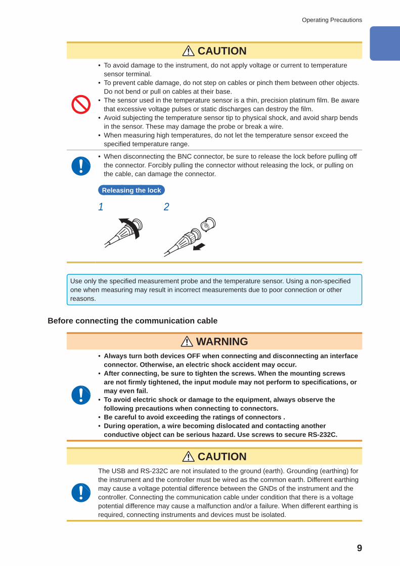
• When disconnecting the BNC connector, be sure to release the lock before pulling off the connector. Forcibly pulling the connector without releasing the lock, or pulling on the cable, can damage the connector.
Releasing the lock
1 2
Use only the specifi ed measurement probe and the temperature sensor. Using a non-specifi ed one when measuring may result in incorrect measurements due to poor connection or other reasons.
Before connecting the communication cable
WARNING • Always turn both devices OFF when connecting and disconnecting an interface connector. Otherwise, an electric shock accident may occur.
• After connecting, be sure to tighten the screws. When the mounting screws are not fi rmly tightened, the input module may not perform to specifi cations, or may even fail.
• To avoid electric shock or damage to the equipment, always observe the following precautions when connecting to connectors.
• Be careful to avoid exceeding the ratings of connectors . • During operation, a wire becoming dislocated and contacting another conductive object can be serious hazard. Use screws to secure RS-232C.
CAUTIONThe USB and RS-232C are not insulated to the ground (earth). Grounding (earthing) for the instrument and the controller must be wired as the common earth. Different earthing may cause a voltage potential difference between the GNDs of the instrument and the controller. Connecting the communication cable under condition that there is a voltage potential difference may cause a malfunction and/or a failure. When different earthing is required, connecting instruments and devices must be isolated.
10
9
8
7
6
5
4
3
2
1
Appx.
Ind.
10
Operating Precautions
Before switching the current sink (NPN) and the current source (PNP)
CAUTIONYou must not operate the EXT.I/O MODE changing over switch (NPN/PNP) during Power-ON status of the instrument.
Set the NPN/PNP based on devices that are externally connected.
Before connecting the EXT.I/O terminals
WARNING • The EXT.I/O of the instrument cannot be applied to from an external power. Do not apply external power to the instrument. (The ISO_5V terminal of the EXT I/O connector is a 5 V (NPN)/-5 V (PNP) power output.)
To avoid electric shock or damage to the instrument, always observe the following precautions when connecting to the connector.
• Always turn off the main power switch to the instrument and to any device to be connected before making connections.
• Be careful to avoid exceeding the ratings of the signal of the EXT.I/O terminals. (p. 111)During operation, a wire becoming dislocated and contacting another conductive object can be serious hazard. Use screws to secure the external connectors.
Precautions during shipmentWhen shipping the instrument, observe the following.Hioki cannot be responsible for damage that occurs during shipment.
CAUTION During shipment of the instrument, handle it carefully so that it is not damaged due to a vibration or shock.
CD disc precautions
IMPORTANT • Exercise care to keep the recorded side of discs free of dirt and scratches. When writing text on a disc’s label, use a pen or marker with a soft tip.
• Keep discs inside a protective case and do not expose to direct sunlight, high temperature, or high humidity.
• Hioki is not liable for any issues your computer system experiences in the course of using this disc.
11
1 Overview
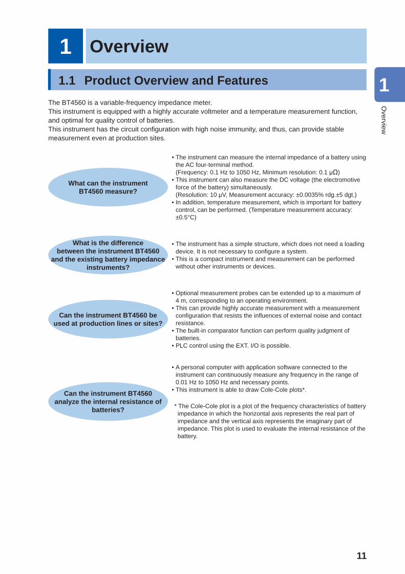
1.1 Product Overview and FeaturesThe BT4560 is a variable-frequency impedance meter.This instrument is equipped with a highly accurate voltmeter and a temperature measurement function, and optimal for quality control of batteries.This instrument has the circuit confi guration with high noise immunity, and thus, can provide stable measurement even at production sites.
What can the instrument BT4560 measure?
• The instrument can measure the internal impedance of a battery using the AC four-terminal method. (Frequency: 0.1 Hz to 1050 Hz, Minimum resolution: 0.1 μΩ)
• This instrument can also measure the DC voltage (the electromotive force of the battery) simultaneously. (Resolution: 10 μV, Measurement accuracy: ±0.0035% rdg.±5 dgt.)
• In addition, temperature measurement, which is important for battery control, can be performed. (Temperature measurement accuracy: ±0.5°C)
What is the difference between the instrument BT4560
and the existing battery impedance instruments?
• The instrument has a simple structure, which does not need a loading device. It is not necessary to confi gure a system.
• This is a compact instrument and measurement can be performed without other instruments or devices.
Can the instrument BT4560 be used at production lines or sites?
• Optional measurement probes can be extended up to a maximum of 4 m, corresponding to an operating environment.
• This can provide highly accurate measurement with a measurement confi guration that resists the infl uences of external noise and contact resistance.
• The built-in comparator function can perform quality judgment of batteries.
• PLC control using the EXT. I/O is possible.
Can the instrument BT4560 analyze the internal resistance of
batteries?
• A personal computer with application software connected to the instrument can continuously measure any frequency in the range of 0.01 Hz to 1050 Hz and necessary points.
• This instrument is able to draw Cole-Cole plots*.
* The Cole-Cole plot is a plot of the frequency characteristics of battery impedance in which the horizontal axis represents the real part of impedance and the vertical axis represents the imaginary part of impedance. This plot is used to evaluate the internal resistance of the battery.
1
Overview
12
Names and Functions of Parts
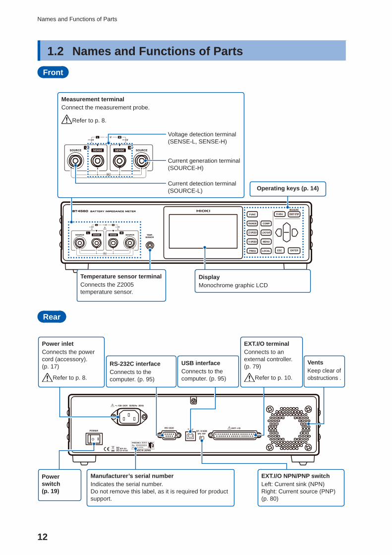
1.2 Names and Functions of PartsFront
DisplayMonochrome graphic LCD
Operating keys (p. 14)
Temperature sensor terminalConnects the Z2005 temperature sensor.
Measurement terminalConnect the measurement probe.
Refer to p. 8.
Voltage detection terminal (SENSE-L, SENSE-H)
Current detection terminal(SOURCE-L)
Current generation terminal(SOURCE-H)
Rear
Power inletConnects the power cord (accessory). (p. 17)
Refer to p. 8.
RS-232C interfaceConnects to the computer. (p. 95)
Manufacturer’s serial numberIndicates the serial number.Do not remove this label, as it is required for product support.
USB interfaceConnects to the computer. (p. 95)
EXT.I/O terminalConnects to an external controller. (p. 79)
Refer to p. 10.
Power switch (p. 19)
EXT.I/O NPN/PNP switchLeft: Current sink (NPN)Right: Current source (PNP)(p. 80)
VentsKeep clear of obstructions .
13
Names and Functions of Parts
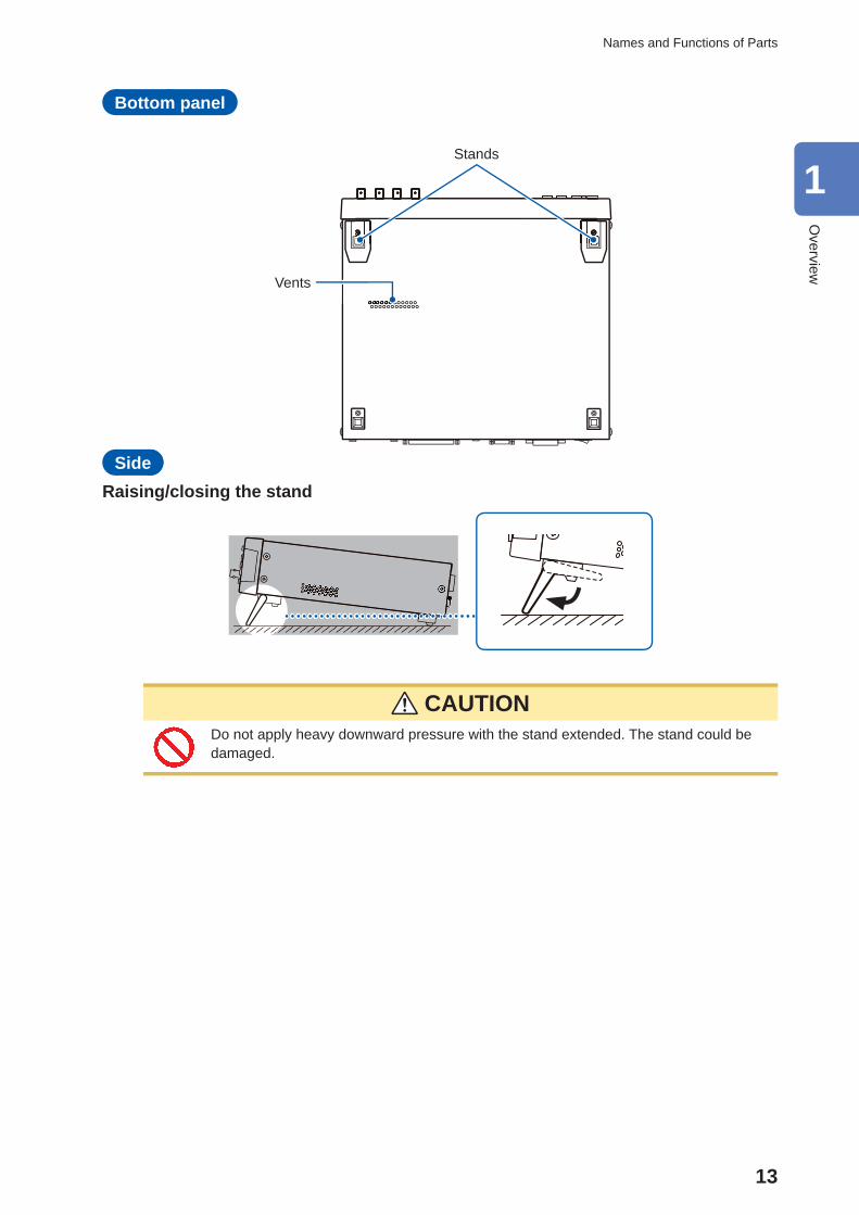
Bottom panel
Stands
Vents
Side Raising/closing the stand
CAUTION Do not apply heavy downward pressure with the stand extended. The stand could be damaged.
1
Overview
14
Names and Functions of Parts
Operating keys
1
2
3
4
5
6
8
7
9
10 11
12
13 14
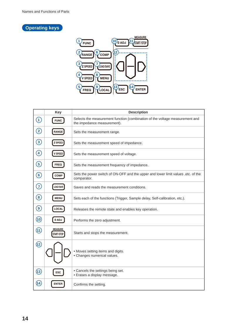
Key Description
1 Selects the measurement function (combination of the voltage measurement and the impedance measurement).
2 Sets the measurement range.
3 Sets the measurement speed of impedance.
4 Sets the measurement speed of voltage.
5 Sets the measurement frequency of impedance.
6 Sets the power switch of ON-OFF and the upper and lower limit values ,etc. of the comparator.
7 Saves and reads the measurement conditions.
8 Sets each of the functions (Trigger, Sample delay, Self-calibration, etc.).
9 Releases the remote state and enables key operation.
10 Performs the zero adjustment.
11 Starts and stops the measurement.
12
• Moves setting items and digits. • Changes numerical values.
13 • Cancels the settings being set. • Erases a display message.
14 Confi rms the setting.
15
Screen Confi guration and Operation
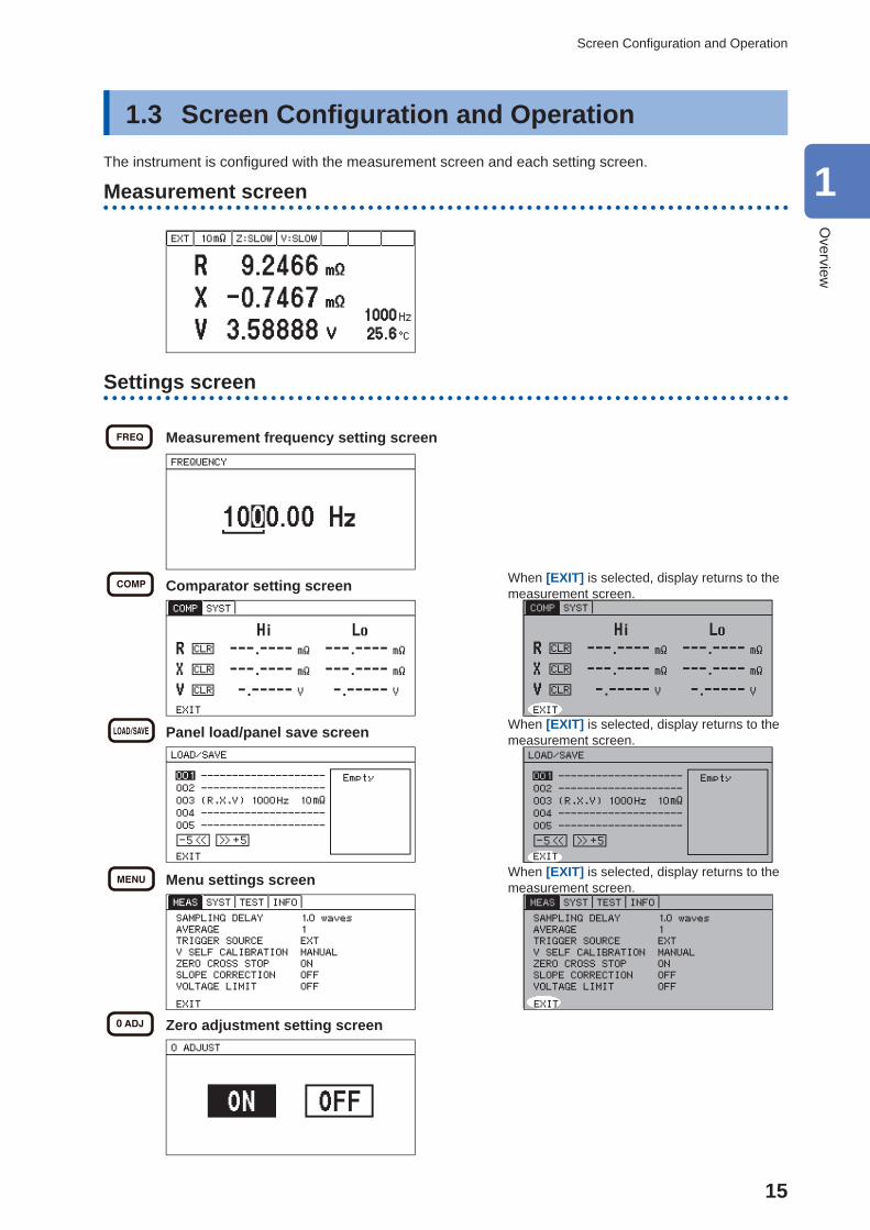
1.3 Screen Confi guration and OperationThe instrument is confi gured with the measurement screen and each setting screen.
Measurement screen
Settings screen
Measurement frequency setting screen
Comparator setting screen When [EXIT] is selected, display returns to the measurement screen.
Panel load/panel save screen When [EXIT] is selected, display returns to the measurement screen.
Menu settings screen When [EXIT] is selected, display returns to the measurement screen.
Zero adjustment setting screen
1
Overview
16
Measurement Flow
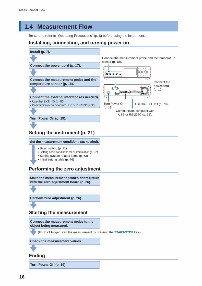
1.4 Measurement FlowBe sure to refer to “Operating Precautions” (p. 6) before using the instrument.
Installing, connecting, and turning power on
Install (p. 7).
Connect the measurement probe and the temperature sensor (p. 18).
Connect the power cord (p. 17).
Use the EXT. I/O (p. 79).
Communicate computer with USB or RS-232C (p. 95).
Turn Power On (p. 19).
Connect the power cord (p. 17).
Connect the measurement probe and the temperature sensor (p. 18).
Connect the external interface (as needed). • Use the EXT. I/O (p. 80). • Communicate computer with USB or RS-232C (p. 95).
Turn Power On (p. 19).
Setting the instrument (p. 21)
Set the measurement conditions (as needed).
• Basic setting (p. 21) • Setting basic conditions for customization (p. 37) • Setting system related items (p. 63) • Initial setting table (p. 76)
Performing the zero adjustment
Make the measurement probes short-circuit with the zero adjustment board (p. 26).
Perform zero adjustment (p. 26).
Starting the measurement
Connect the measurement probe to the object being measured.
(For EXT trigger, start the measurement by pressing the START/STOP key.)
Check the measurement values.
Ending
Turn Power Off (p. 19).
17
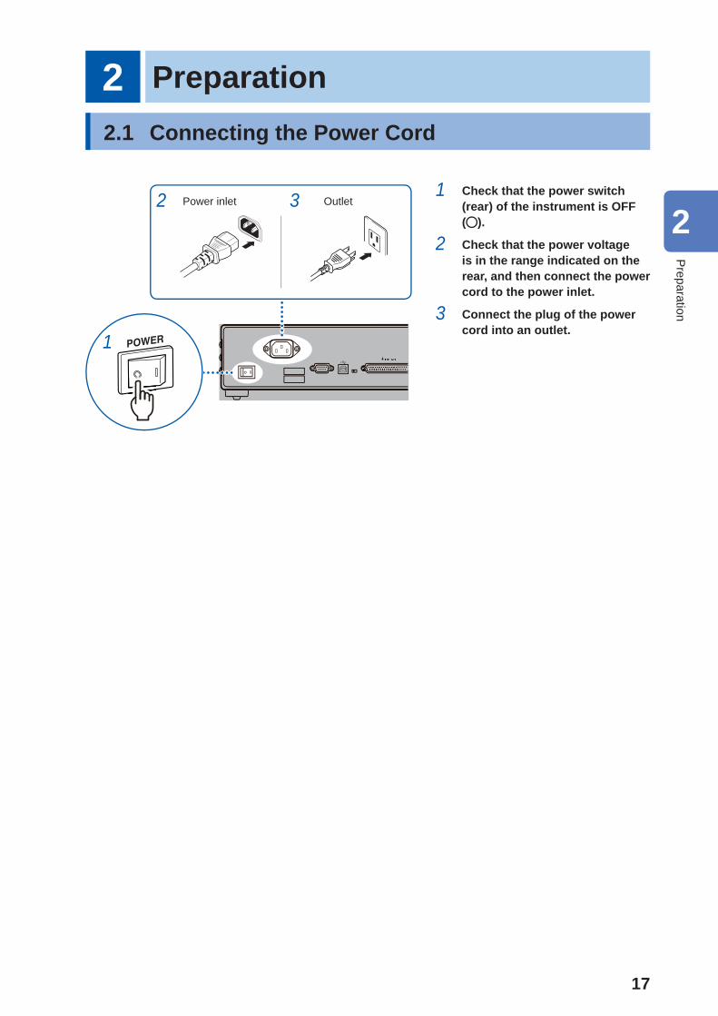
2 Preparation2.1 Connecting the Power Cord
Power inlet Outlet2 3
1
1 Check that the power switch (rear) of the instrument is OFF ( ).
2 Check that the power voltage is in the range indicated on the rear, and then connect the power cord to the power inlet.
3 Connect the plug of the power cord into an outlet.
2
Preparation
18
Connecting the Measurement Probe and Temperature Sensor (Optional)
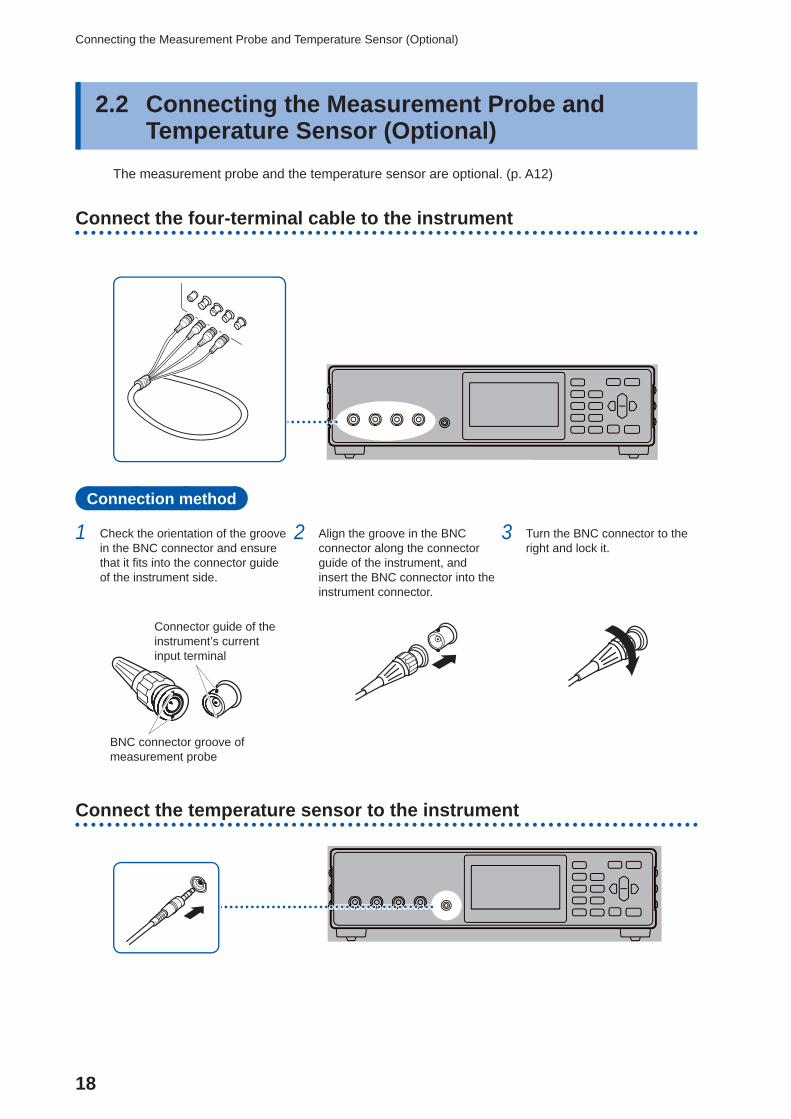
2.2 Connecting the Measurement Probe and Temperature Sensor (Optional)
The measurement probe and the temperature sensor are optional. (p. A12)
Connect the four-terminal cable to the instrument
Connection method
1 Check the orientation of the groove in the BNC connector and ensure that it fi ts into the connector guide of the instrument side.
2 Align the groove in the BNC connector along the connector guide of the instrument, and insert the BNC connector into the instrument connector.
3 Turn the BNC connector to the right and lock it.
Connector guide of the instrument’s current input terminal
BNC connector groove of measurement probe
Connect the temperature sensor to the instrument
19
Turning the Power ON or OFF
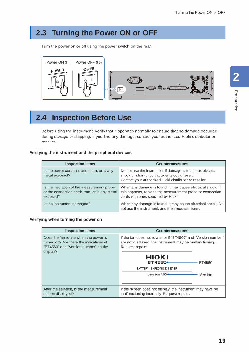
2.3 Turning the Power ON or OFFTurn the power on or off using the power switch on the rear.
Power OFF ( )Power ON (I)
2.4 Inspection Before Use Before using the instrument, verify that it operates normally to ensure that no damage occurred during storage or shipping. If you fi nd any damage, contact your authorized Hioki distributor or reseller.
Verifying the instrument and the peripheral devices
Inspection items Countermeasures
Is the power cord insulation torn, or is any metal exposed?
Do not use the instrument if damage is found, as electric shock or short-circuit accidents could result.Contact your authorized Hioki distributor or reseller.
Is the insulation of the measurement probe or the connection cords torn, or is any metal exposed?
When any damage is found, it may cause electrical shock. If this happens, replace the measurement probe or connection cords with ones specifi ed by Hioki.
Is the instrument damaged? When any damage is found, it may cause electrical shock. Do not use the instrument, and then request repair.
Verifying when turning the power on
Inspection items Countermeasures
Does the fan rotate when the power is turned on? Are there the indications of “BT4560” and “Version number” on the display?
If the fan does not rotate, or if “BT4560” and “Version number” are not displayed, the instrument may be malfunctioning. Request repairs.
Version
BT4560
After the self-test, is the measurement screen displayed?
If the screen does not display, the instrument may have be malfunctioning internally. Request repairs.
2
Preparation

20
Inspection Before Use
21
3 Basic Measurement3.1 Selecting the Measurement Functions
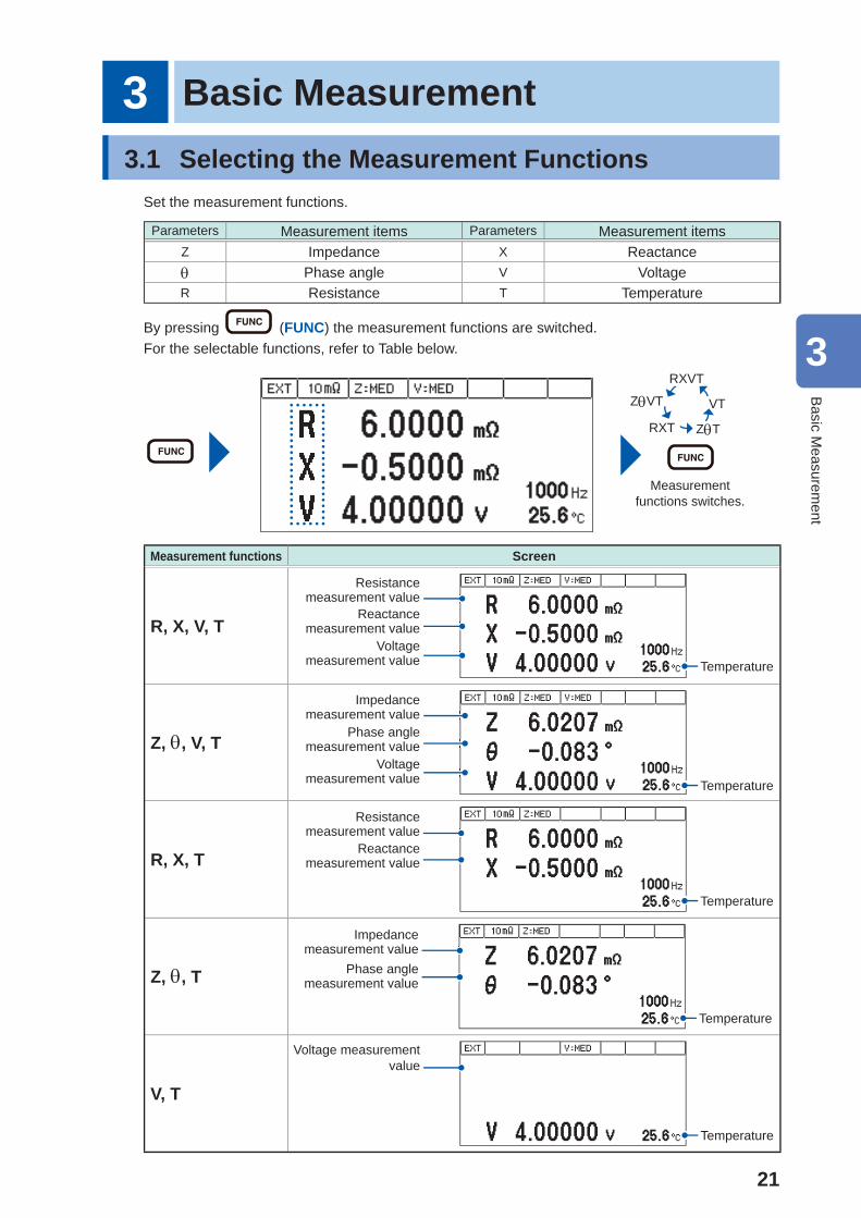
Set the measurement functions.
Parameters Measurement items Parameters Measurement itemsZ Impedance X Reactance Phase angle V VoltageR Resistance T Temperature
By pressing (FUNC) the measurement functions are switched.For the selectable functions, refer to Table below.
Measurement functions switches.
ZVT
RXVT
T
RXT ZT
VTVVVVVVVVV
Measurement functions Screen
R, X, V, T
Resistance measurement value
Reactance measurement value
Voltage measurement value Temperature
Z, , V, T
Impedance measurement value
Phase angle measurement value
Voltage measurement value Temperature
R, X, T
Resistance measurement value
Reactance measurement value
Temperature
Z, , T
Impedance measurement value
Phase angle measurement value
Temperature
V, T
Voltage measurement value
Temperature
3
Basic M
easurement
22
Selecting the Measurement Range
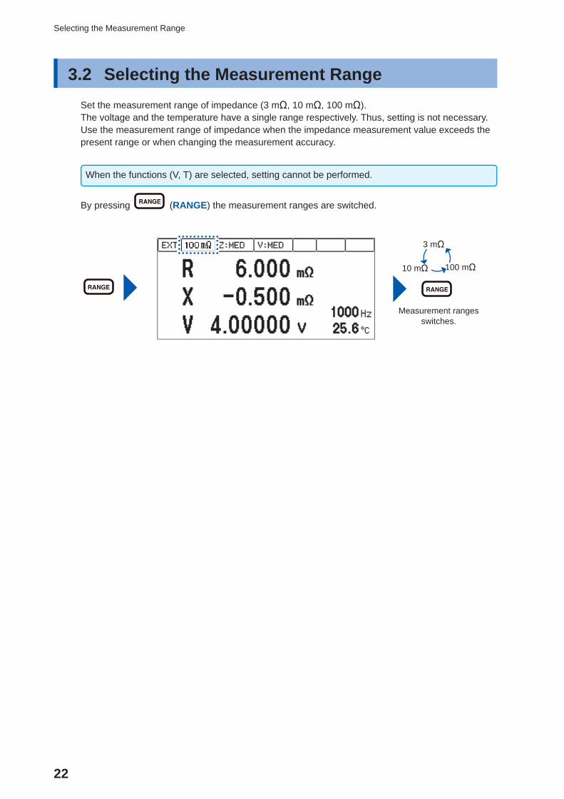
3.2 Selecting the Measurement Range Set the measurement range of impedance (3 mΩ, 10 mΩ, 100 mΩ).The voltage and the temperature have a single range respectively. Thus, setting is not necessary. Use the measurement range of impedance when the impedance measurement value exceeds the present range or when changing the measurement accuracy.
When the functions (V, T) are selected, setting cannot be performed.
By pressing (RANGE) the measurement ranges are switched.
Measurement ranges switches.
3 mΩ
10 mΩ 100 mΩ111111111111
23
Setting the Measurement Speed
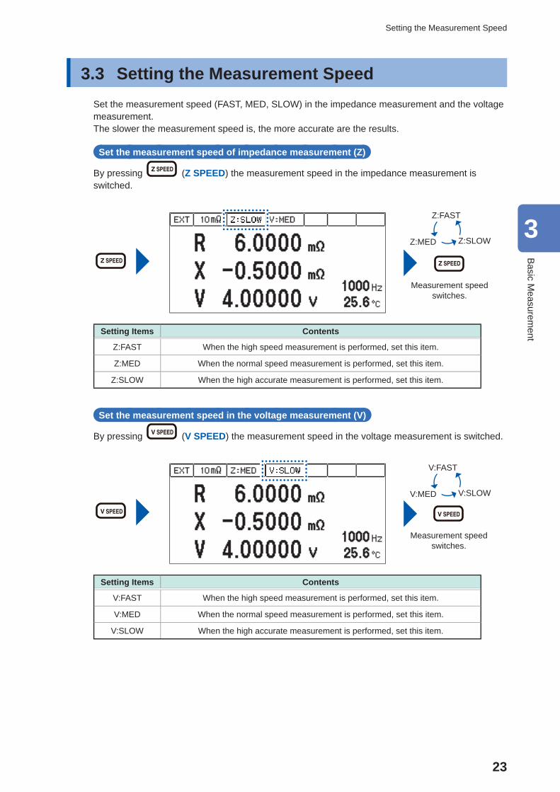
3.3 Setting the Measurement Speed Set the measurement speed (FAST, MED, SLOW) in the impedance measurement and the voltage measurement.The slower the measurement speed is, the more accurate are the results.
Set the measurement speed of impedance measurement (Z)
By pressing (Z SPEED) the measurement speed in the impedance measurement is switched.
Measurement speed switches.
Z:FAST
Z:MED Z:SLOW
Setting Items Contents
Z:FAST When the high speed measurement is performed, set this item.
Z:MED When the normal speed measurement is performed, set this item.
Z:SLOW When the high accurate measurement is performed, set this item.
Set the measurement speed in the voltage measurement (V)
By pressing (V SPEED) the measurement speed in the voltage measurement is switched.
Measurement speed switches.
V:FAST
V:MED V:SLOW
Setting Items Contents
V:FAST When the high speed measurement is performed, set this item.
V:MED When the normal speed measurement is performed, set this item.
V:SLOW When the high accurate measurement is performed, set this item.
3
Basic M
easurement
24
Setting the Measurement Frequency
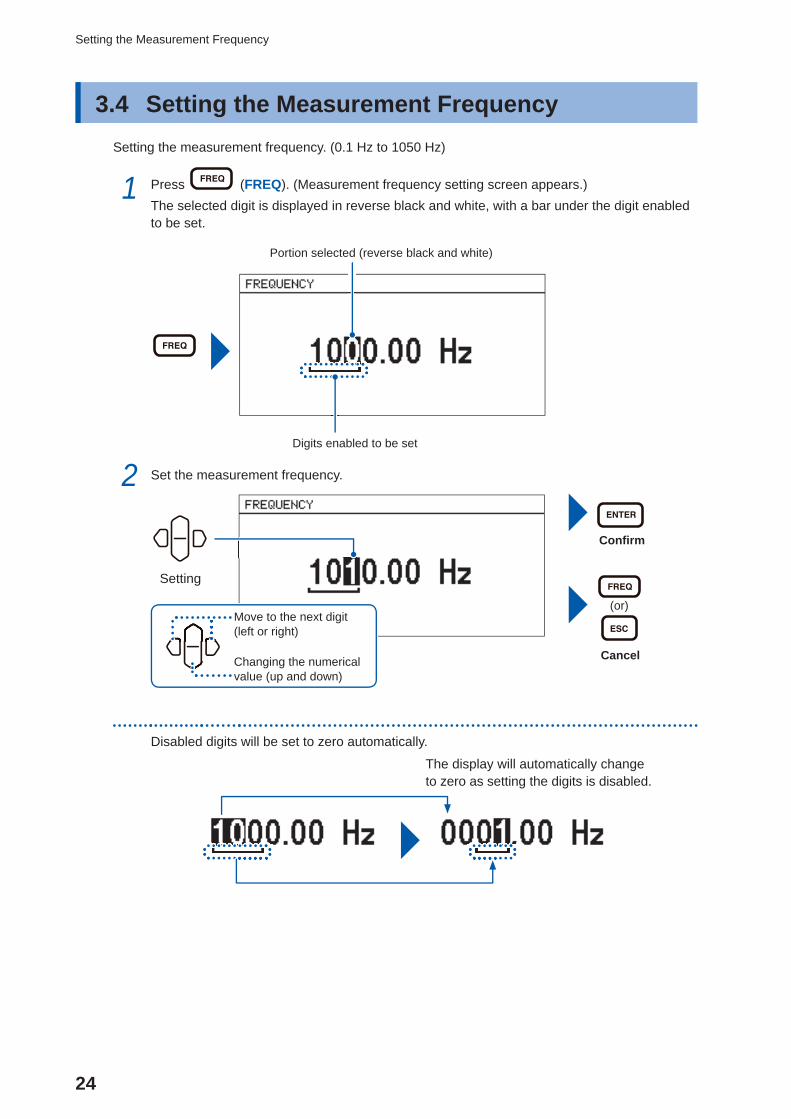
3.4 Setting the Measurement FrequencySetting the measurement frequency. (0.1 Hz to 1050 Hz)
1 Press (FREQ). (Measurement frequency setting screen appears.)The selected digit is displayed in reverse black and white, with a bar under the digit enabled to be set.
Portion selected (reverse black and white)
Digits enabled to be set
2 Set the measurement frequency.
Confi rm
(or)
Cancel
Setting
Move to the next digit (left or right)
Changing the numerical value (up and down)
Disabled digits will be set to zero automatically.
The display will automatically change to zero as setting the digits is disabled.
25
Setting the Measurement Frequency
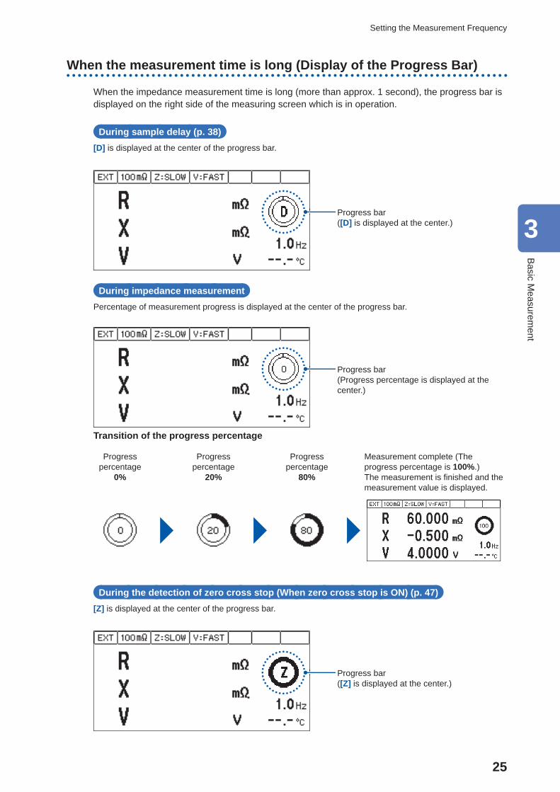
When the measurement time is long (Display of the Progress Bar)
When the impedance measurement time is long (more than approx. 1 second), the progress bar is displayed on the right side of the measuring screen which is in operation.
During sample delay (p. 38)[D] is displayed at the center of the progress bar.
Progress bar([D] is displayed at the center.)
During impedance measurementPercentage of measurement progress is displayed at the center of the progress bar.
Progress bar(Progress percentage is displayed at the center.)
Transition of the progress percentage
Progress percentage
0%
Progress percentage
20%
Progress percentage
80%
Measurement complete (The progress percentage is 100%.)The measurement is fi nished and the measurement value is displayed.
During the detection of zero cross stop (When zero cross stop is ON) (p. 47)[Z] is displayed at the center of the progress bar.
Progress bar([Z] is displayed at the center.)
3
Basic M
easurement
26
Performing the Zero Adjustment
3.5 Performing the Zero AdjustmentRemove the residual components due to offset and the measurement environment.Be sure to perform the zero adjustment before the impedance measurement and the voltage measurement.
Performing the zero adjustment
Placing the measurement probe (Example: L2002)
1 Place the measurement probe in the same condition as the measurement is performed.The zero residual volume differs due to the condition of the measurement probe (length, shape, and location). Thus, place the measurement probe in the same condition as the actual measurement is performed, before performing the zero adjustment.
2 Prepare the zero adjustment board (accessory).
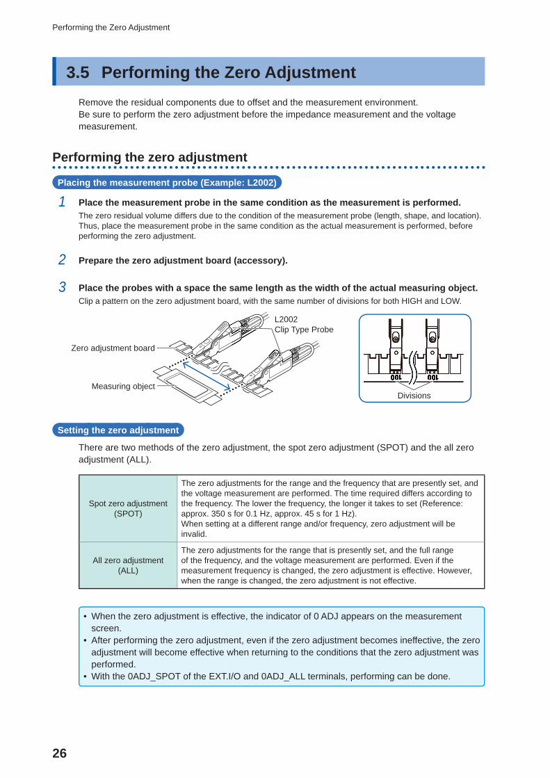
3 Place the probes with a space the same length as the width of the actual measuring object.Clip a pattern on the zero adjustment board, with the same number of divisions for both HIGH and LOW.
Measuring object
Zero adjustment board
L2002Clip Type Probe
Divisions
Cl
Setting the zero adjustment
There are two methods of the zero adjustment, the spot zero adjustment (SPOT) and the all zero adjustment (ALL).
Spot zero adjustment (SPOT)
The zero adjustments for the range and the frequency that are presently set, and the voltage measurement are performed. The time required differs according to the frequency. The lower the frequency, the longer it takes to set (Reference: approx. 350 s for 0.1 Hz, approx. 45 s for 1 Hz).When setting at a different range and/or frequency, zero adjustment will be invalid.
All zero adjustment (ALL)
The zero adjustments for the range that is presently set, and the full range of the frequency, and the voltage measurement are performed. Even if the measurement frequency is changed, the zero adjustment is effective. However, when the range is changed, the zero adjustment is not effective.
• When the zero adjustment is effective, the indicator of 0 ADJ appears on the measurement screen.
• After performing the zero adjustment, even if the zero adjustment becomes ineffective, the zero adjustment will become effective when returning to the conditions that the zero adjustment was performed.
• With the 0ADJ_SPOT of the EXT.I/O and 0ADJ_ALL terminals, performing can be done.
27
Performing the Zero Adjustment
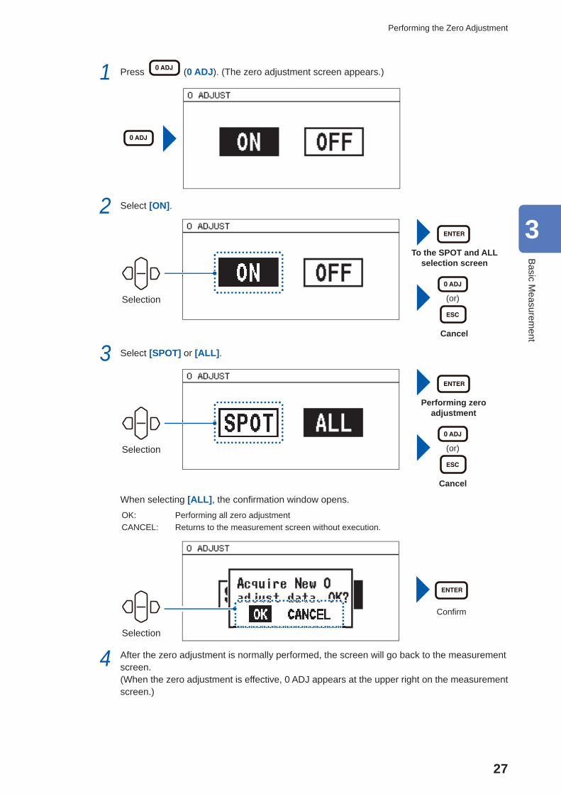
1 Press (0 ADJ). (The zero adjustment screen appears.)
2 Select [ON].
Selection
To the SPOT and ALL selection screen
(or)
Cancel
3 Select [SPOT] or [ALL].
Selection
Performing zero adjustment
(or)
Cancel
When selecting [ALL], the confi rmation window opens.OK: Performing all zero adjustmentCANCEL: Returns to the measurement screen without execution.
Selection
Confi rm
4 After the zero adjustment is normally performed, the screen will go back to the measurement screen. (When the zero adjustment is effective, 0 ADJ appears at the upper right on the measurement screen.)
3
Basic M
easurement
28
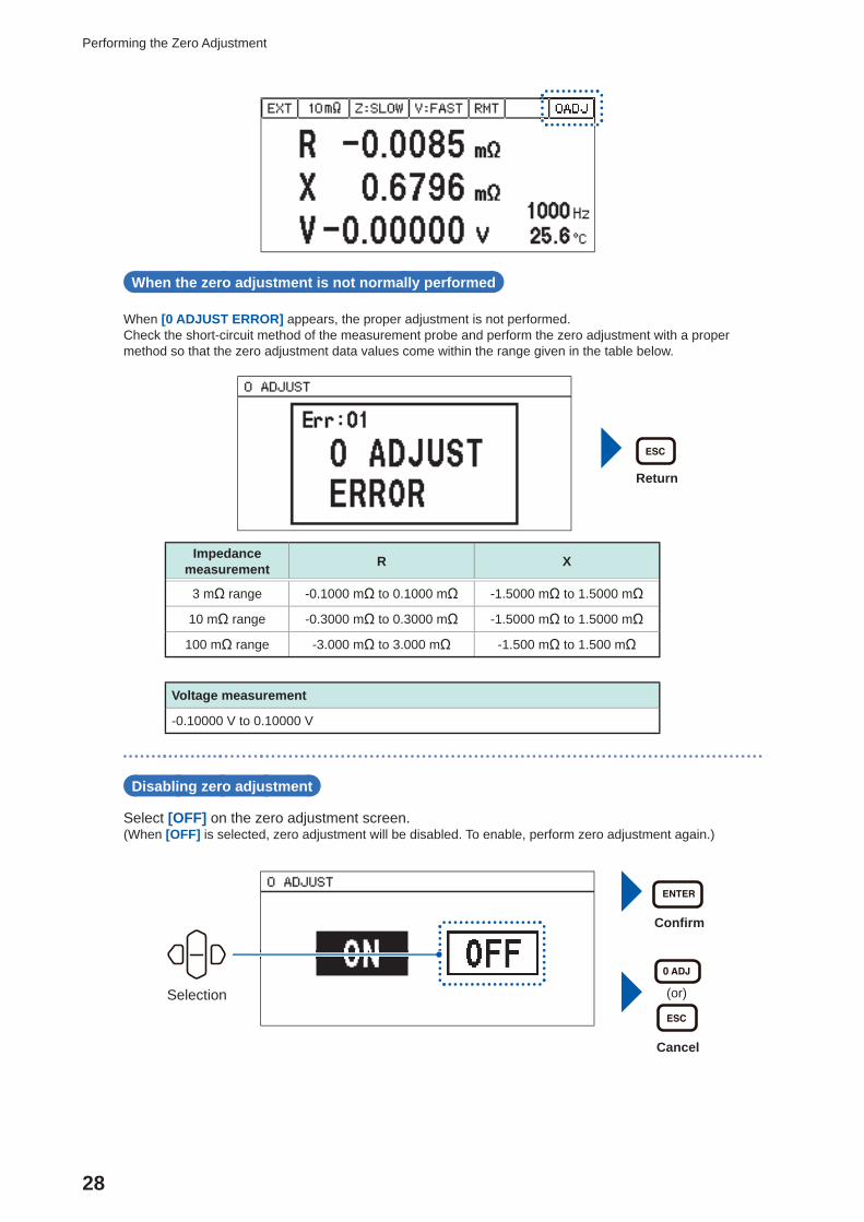
Performing the Zero Adjustment
When the zero adjustment is not normally performed
When [0 ADJUST ERROR] appears, the proper adjustment is not performed.Check the short-circuit method of the measurement probe and perform the zero adjustment with a proper method so that the zero adjustment data values come within the range given in the table below.
Return
Impedance measurement R X
3 mΩ range -0.1000 mΩ to 0.1000 mΩ -1.5000 mΩ to 1.5000 mΩ
10 mΩ range -0.3000 mΩ to 0.3000 mΩ -1.5000 mΩ to 1.5000 mΩ
100 mΩ range -3.000 mΩ to 3.000 mΩ -1.500 mΩ to 1.500 mΩ
Voltage measurement
-0.10000 V to 0.10000 V
Disabling zero adjustment
Select [OFF] on the zero adjustment screen.(When [OFF] is selected, zero adjustment will be disabled. To enable, perform zero adjustment again.)
Selection
Confi rm
(or)
Cancel
29
Performing the Zero Adjustment
When measuring while changing the measurement rangeIf measured as below, zero adjustment will not be necessary every time the range is changed.1. Perform zero adjustment at 3 mΩ range.2. Save the current condition by panel saving function (p. 58).
(Zero adjustment data of the current range will be saved.)3. Change the range to 10 mΩ and perform zero adjustment.4. Save the current condition by panel saving function (p. 58).5. Change the range to 100 mΩ and perform zero adjustment.6. Save the current condition by panel saving function (p. 58).7. Read the condition of the range used by panel saving function (p. 58), and then measure.
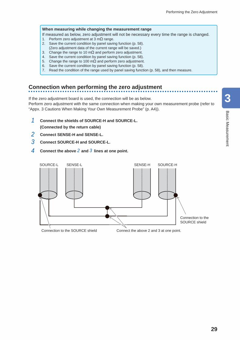
Connection when performing the zero adjustment
If the zero adjustment board is used, the connection will be as below.Perform zero adjustment with the same connection when making your own measurement probe (refer to “Appx. 3 Cautions When Making Your Own Measurement Probe” (p. A4)).
1 Connect the shields of SOURCE-H and SOURCE-L.(Connected by the return cable)
2 Connect SENSE-H and SENSE-L.
3 Connect SOURCE-H and SOURCE-L.
4 Connect the above 2 and 3 lines at one point.
SENSE-HSENSE-L SOURCE-HSOURCE-L
Connection to the SOURCE shield Connect the above 2 and 3 at one point.
Connection to the SOURCE shield
3
Basic M
easurement
30
Checking the Measurement Results
3.6 Checking the Measurement Results
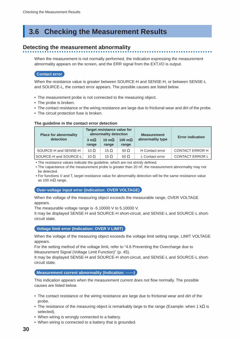
Detecting the measurement abnormality
When the measurement is not normally performed, the indication expressing the measurement abnormality appears on the screen, and the ERR signal from the EXT.I/O is output.
Contact error
When the resistance value is greater between SOURCE-H and SENSE-H, or between SENSE-L and SOURCE-L, the contact error appears. The possible causes are listed below.
• The measurement probe is not connected to the measuring object. • The probe is broken. • The contact resistance or the wiring resistance are large due to frictional wear and dirt of the probe. • The circuit protection fuse is broken.
The guideline in the contact error detection
Place for abnormality detection
Target resistance value for abnormality detection Measurement
abnormality type Error indication3 mΩ range
10 mΩ range
100 mΩ range
SOURCE-H and SENSE-H 10 Ω 15 Ω 50 Ω H Contact error CONTACT ERROR HSOURCE-H and SOURCE-L 10 Ω 15 Ω 50 Ω L Contact error CONTACT ERROR L • The resistance values indicate the guideline, which are not strictly defi ned. • The capacitance of the measurement probe is greater than 20 nF, the measurement abnormality may not be detected.
• For functions V and T, target resistance value for abnormality detection will be the same resistance value as 100 mΩ range.
Over-voltage input error (indication: OVER VOLTAGE)
When the voltage of the measuring object exceeds the measurable range, OVER VOLTAGE appears.The measurable voltage range is -5.10000 V to 5.10000 V.It may be displayed SENSE-H and SOURCE-H short-circuit, and SENSE-L and SOURCE-L short-circuit state.
Voltage limit error (Indication: OVER V LIMIT)
When the voltage of the measuring object exceeds the voltage limit setting range, LIMIT VOLTAGE appears.For the setting method of the voltage limit, refer to “4.6 Preventing the Overcharge due to Measurement Signal (Voltage Limit Function)” (p. 45).It may be displayed SENSE-H and SOURCE-H short-circuit, and SENSE-L and SOURCE-L short-circuit state.
Measurement current abnormality (Indication: ------)
This indication appears when the measurement current does not fl ow normally. The possible causes are listed below.
• The contact resistance or the wiring resistance are large due to frictional wear and dirt of the probe.
• The resistance of the measuring object is remarkably large to the range (Example: when 1 kΩ is selected).
• When wiring is wrongly connected to a battery. • When wiring is connected to a battery that is grounded.
31
Checking the Measurement Results
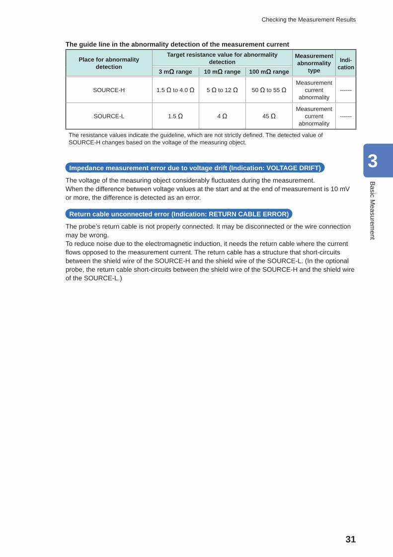
The guide line in the abnormality detection of the measurement current
Place for abnormality detection
Target resistance value for abnormality detection
Measurement abnormality
type
Indi-cation
3 mΩ range 10 mΩ range 100 mΩ range
SOURCE-H 1.5 Ω to 4.0 Ω 5 Ω to 12 Ω 50 Ω to 55 ΩMeasurement
current abnormality
------
SOURCE-L 1.5 Ω 4 Ω 45 ΩMeasurement
current abnormality
------
The resistance values indicate the guideline, which are not strictly defi ned. The detected value of SOURCE-H changes based on the voltage of the measuring object.
Impedance measurement error due to voltage drift (Indication: VOLTAGE DRIFT)
The voltage of the measuring object considerably fl uctuates during the measurement.When the difference between voltage values at the start and at the end of measurement is 10 mV or more, the difference is detected as an error.
Return cable unconnected error (Indication: RETURN CABLE ERROR)
The probe’s return cable is not properly connected. It may be disconnected or the wire connection may be wrong.To reduce noise due to the electromagnetic induction, it needs the return cable where the current fl ows opposed to the measurement current. The return cable has a structure that short-circuits between the shield wire of the SOURCE-H and the shield wire of the SOURCE-L. (In the optional probe, the return cable short-circuits between the shield wire of the SOURCE-H and the shield wire of the SOURCE-L.)
3
Basic M
easurement
32
Checking the Measurement Results
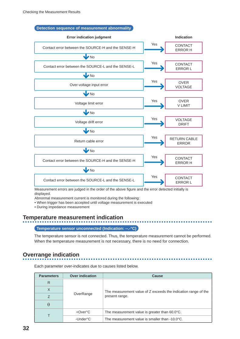
Detection sequence of measurement abnormality
Error indication judgment Indication
Contact error between the SOURCE-H and the SENSE-HYes CONTACT
ERROR H
No
Contact error between the SOURCE-L and the SENSE-LYes CONTACT
ERROR L
No
Over-voltage input errorYes OVER
VOLTAGE
No
Voltage limit errorYes OVER
V LIMIT
No
Voltage drift errorYes VOLTAGE
DRIFT
No
Return cable errorYes RETURN CABLE
ERROR
No
Contact error between the SOURCE-H and the SENSE-HYes CONTACT
ERROR H
No
Contact error between the SOURCE-L and the SENSE-LYes CONTACT
ERROR L
Measurement errors are judged in the order of the above fi gure and the error detected initially is displayed.Abnormal measurement current is monitored during the following: • When trigger has been accepted until voltage measurement is executed • During impedance measurement
Temperature measurement indication
Temperature sensor unconnected (Indication: --.-°C)
The temperature sensor is not connected. Thus, the temperature measurement cannot be performed.When the temperature measurement is not necessary, there is no need for connection.
Overrange indication
Each parameter over-indicates due to causes listed below.
Parameters Over indication Cause
R
OverRange The measurement value of Z exceeds the indication range of the present range.
X
Z
T+Over°C The measurement value is greater than 60.0°C.
-Under°C The measurement value is smaller than -10.0°C.
33
Basic Measurement Examples
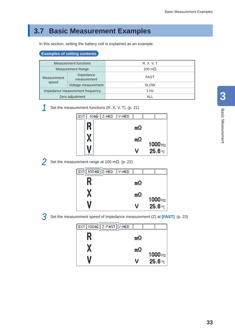
3.7 Basic Measurement Examples In this section, setting the battery cell is explained as an example.
Examples of setting contents
Measurement functions R, X, V, TMeasurement Range 100 mΩ
Measurement speed
Impedance measurement FAST
Voltage measurement SLOWImpedance measurement frequency 1 Hz
Zero adjustment ALL
1 Set the measurement functions (R, X, V, T). (p. 21)
2 Set the measurement range at 100 mΩ. (p. 22)
3 Set the measurement speed of impedance measurement (Z) at [FAST]. (p. 23)
3
Basic M
easurement
34
Basic Measurement Examples
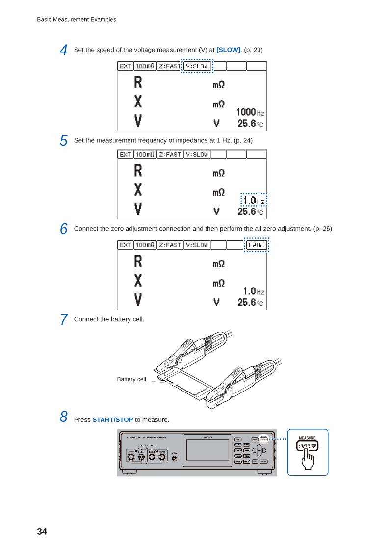
4 Set the speed of the voltage measurement (V) at [SLOW]. (p. 23)
5 Set the measurement frequency of impedance at 1 Hz. (p. 24)
6 Connect the zero adjustment connection and then perform the all zero adjustment. (p. 26)
7 Connect the battery cell.
Battery cell
8 Press START/STOP to measure.
35
Basic Measurement Examples
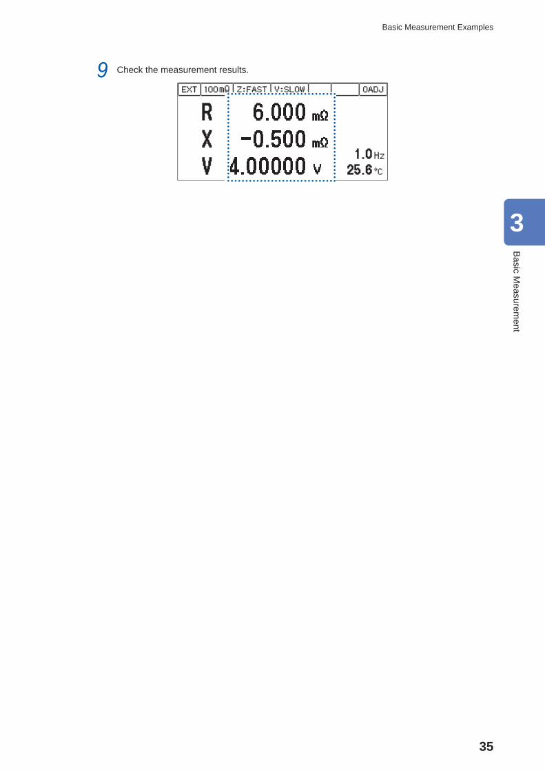
9 Check the measurement results.
3
Basic M
easurement

36
Basic Measurement Examples
37
4 Customization of Measurement Conditions
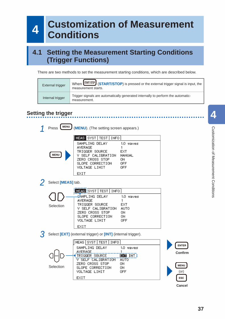
4.1 Setting the Measurement Starting Conditions ( Trigger Functions)
There are two methods to set the measurement starting conditions, which are described below.
External trigger When (START/STOP) is pressed or the external trigger signal is input, the measurement starts.
Internal trigger Trigger signals are automatically generated internally to perform the automatic-measurement.
Setting the trigger
1 Press (MENU). (The setting screen appears.)
2 Select [MEAS] tab.
Selection
3 Select [EXT] (external trigger) or [INT] (internal trigger).
Selection
Confi rm
(or)
Cancel
4
Custom
ization of Measurem
ent Conditions
38
Starting the Measurement After the Response of the Measuring Object is Stable (Sample Delay Function)
Inputting the external trigger
• When inputting from the keyOn the measurement screen, press (START/STOP) to perform measurement once.
• When inputting from the EXT.I/OIf the TRIG terminal of the EXT.I/O terminal is short-circuited to ISO_COM, the measurement is performed once. (p. 80)
• When inputting from the communication interfaceWhen the *TRIG command is received, measurement is performed once.
IMPORTANT • When the function is set in the internal trigger, the input from the EXT.I/O and *TRG command are ignored, and the voltage limit function is enabled. If the measuring object continues to be connected with an internal trigger set, may cause continuous charging or discharging. Therefore, remove the measuring object from the instrument after measurement.
• Measurement will stop if (START/STOP) is pressed during measurement.
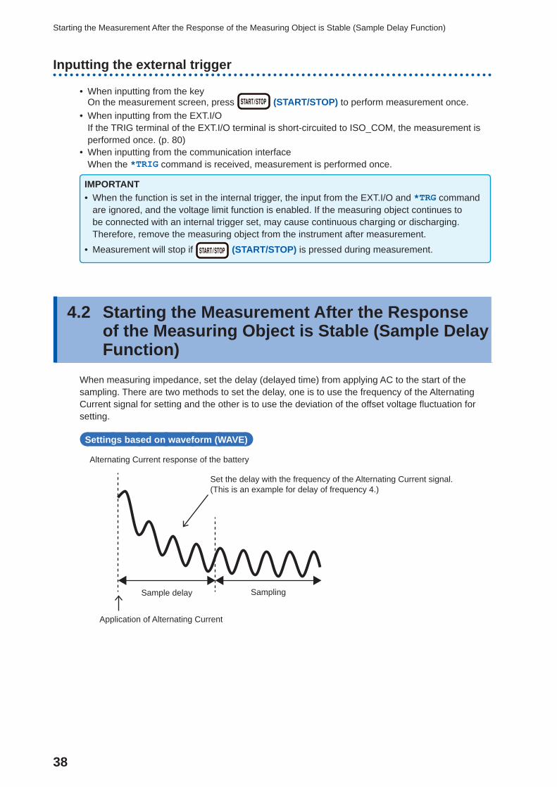
4.2 Starting the Measurement After the Response of the Measuring Object is Stable ( Sample Delay Function)
When measuring impedance, set the delay (delayed time) from applying AC to the start of the sampling. There are two methods to set the delay, one is to use the frequency of the Alternating Current signal for setting and the other is to use the deviation of the offset voltage fl uctuation for setting.
Settings based on waveform (WAVE)
Alternating Current response of the battery
Application of Alternating Current
Set the delay with the frequency of the Alternating Current signal.(This is an example for delay of frequency 4.)
Sample delay Sampling
39
Starting the Measurement After the Response of the Measuring Object is Stable (Sample Delay Function)
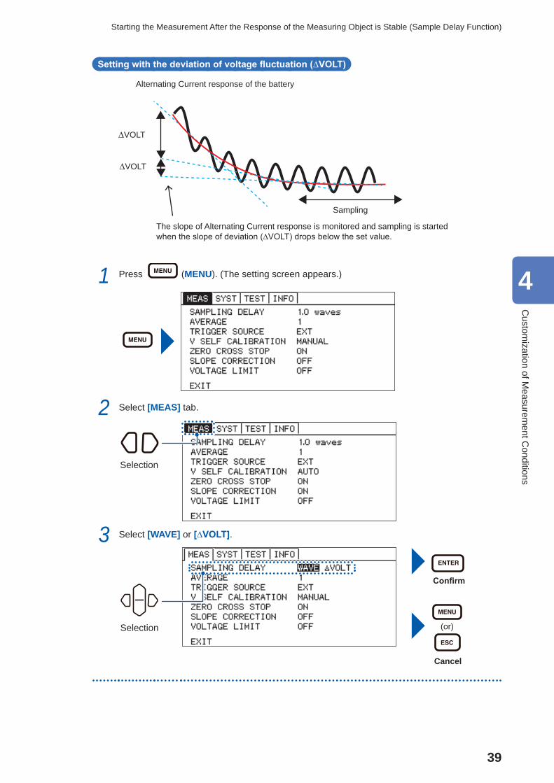
Setting with the deviation of voltage fluctuation (∆VOLT)
Alternating Current response of the battery
Sampling
∆VOLT
∆VOLT
The slope of Alternating Current response is monitored and sampling is started when the slope of deviation (∆VOLT) drops below the set value.
1 Press (MENU). (The setting screen appears.)
2 Select [MEAS] tab.
Selection
3 Select [WAVE] or [∆VOLT].
Confirm
(or)
Cancel
Selection
4
Custom
ization of Measurem
ent Conditions
40
Starting the Measurement After the Response of the Measuring Object is Stable (Sample Delay Function)
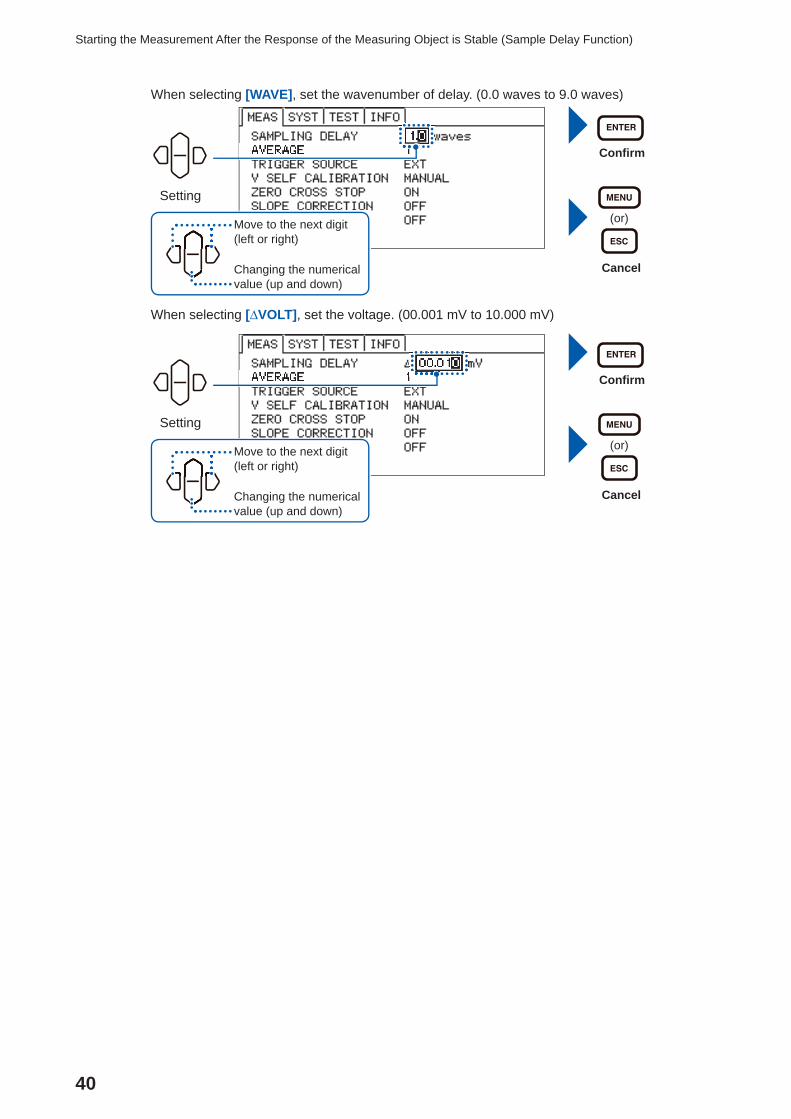
When selecting [WAVE], set the wavenumber of delay. (0.0 waves to 9.0 waves)
Setting
Confi rm
(or)
Cancel
Move to the next digit (left or right)
Changing the numerical value (up and down)
When selecting [∆VOLT], set the voltage. (00.001 mV to 10.000 mV)
Setting
Confi rm
(or)
Cancel
Move to the next digit (left or right)
Changing the numerical value (up and down)
41
Maintaining Voltage Measurement Accuracy (Self-Calibration Function)
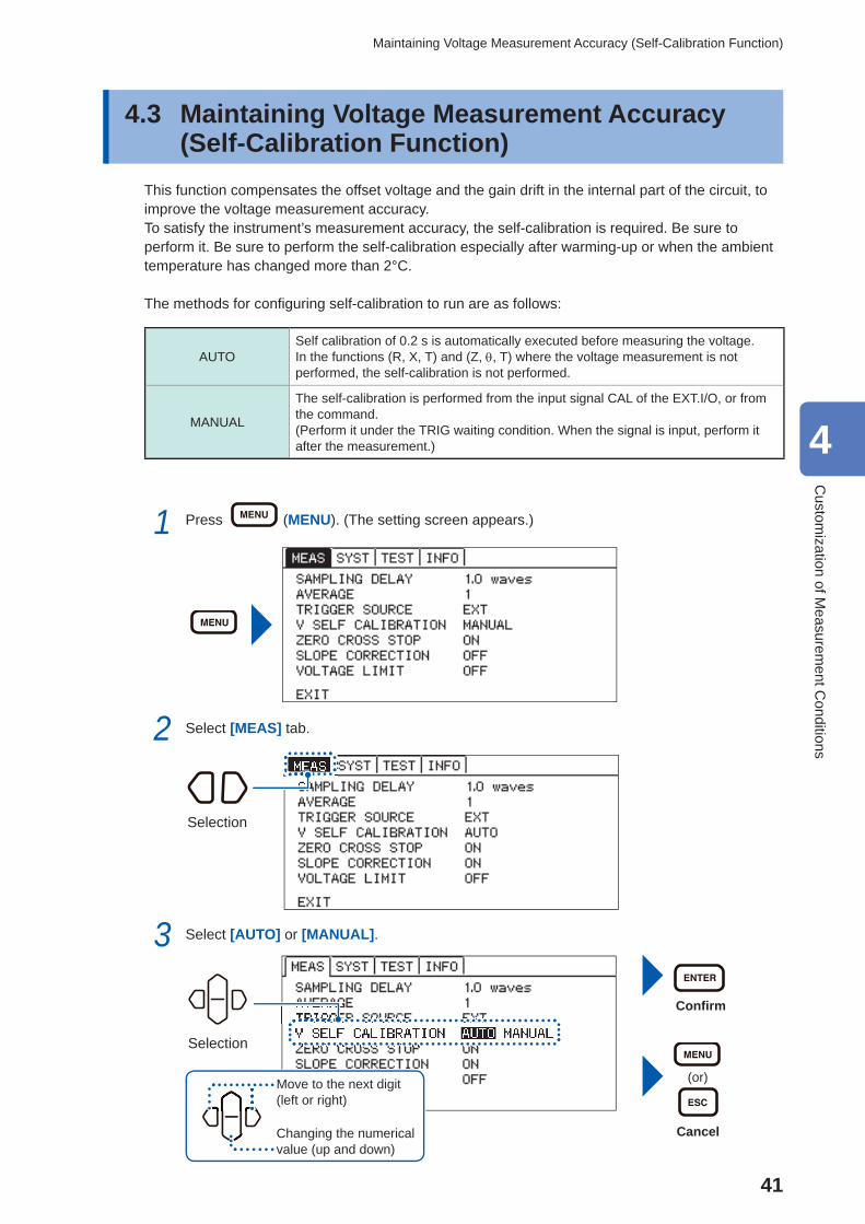
4.3 Maintaining Voltage Measurement Accuracy ( Self-Calibration Function)
This function compensates the offset voltage and the gain drift in the internal part of the circuit, to improve the voltage measurement accuracy.To satisfy the instrument’s measurement accuracy, the self-calibration is required. Be sure to perform it. Be sure to perform the self-calibration especially after warming-up or when the ambient temperature has changed more than 2°C.
The methods for confi guring self-calibration to run are as follows:
AUTOSelf calibration of 0.2 s is automatically executed before measuring the voltage. In the functions (R, X, T) and (Z, , T) where the voltage measurement is not performed, the self-calibration is not performed.
MANUAL
The self-calibration is performed from the input signal CAL of the EXT.I/O, or from the command. (Perform it under the TRIG waiting condition. When the signal is input, perform it after the measurement.)
1 Press (MENU). (The setting screen appears.)
2 Select [MEAS] tab.
Selection
3 Select [AUTO] or [MANUAL].
Selection
Confi rm
(or)
Cancel
Move to the next digit (left or right)
Changing the numerical value (up and down)
4
Custom
ization of Measurem
ent Conditions
42
Stabilizing the Measurement Values (Average Function)
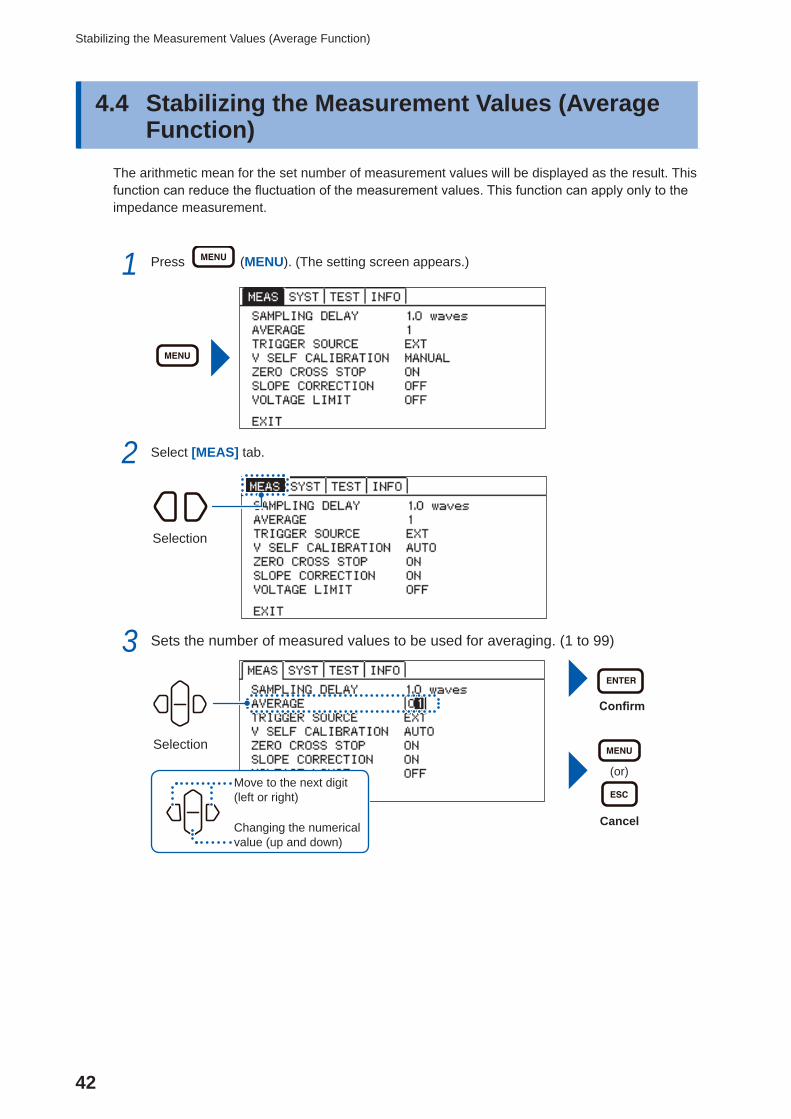
4.4 Stabilizing the Measurement Values (Average Function)
The arithmetic mean for the set number of measurement values will be displayed as the result. This function can reduce the fluctuation of the measurement values. This function can apply only to the impedance measurement.
1 Press (MENU). (The setting screen appears.)
2 Select [MEAS] tab.
Selection
3 Sets the number of measured values to be used for averaging. (1 to 99)
Confirm
(or)
Cancel
Selection
Move to the next digit (left or right)
Changing the numerical value (up and down)
43
Compensating the Potential Slope Due to Electric Discharge (Slope Correction Function)
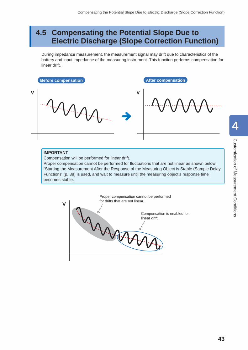
4.5 Compensating the Potential Slope Due to Electric Discharge ( Slope Correction Function)
During impedance measurement, the measurement signal may drift due to characteristics of the battery and input impedance of the measuring instrument. This function performs compensation for linear drift.
V V
Before compensation After compensation
IMPORTANTCompensation will be performed for linear drift.Proper compensation cannot be performed for fl uctuations that are not linear as shown below. “Starting the Measurement After the Response of the Measuring Object is Stable (Sample Delay Function)” (p. 38) is used, and wait to measure until the measuring object’s response time becomes stable.
VProper compensation cannot be performed for drifts that are not linear.
Compensation is enabled for linear drift.
4
Custom
ization of Measurem
ent Conditions
44
Compensating the Potential Slope Due to Electric Discharge (Slope Correction Function)
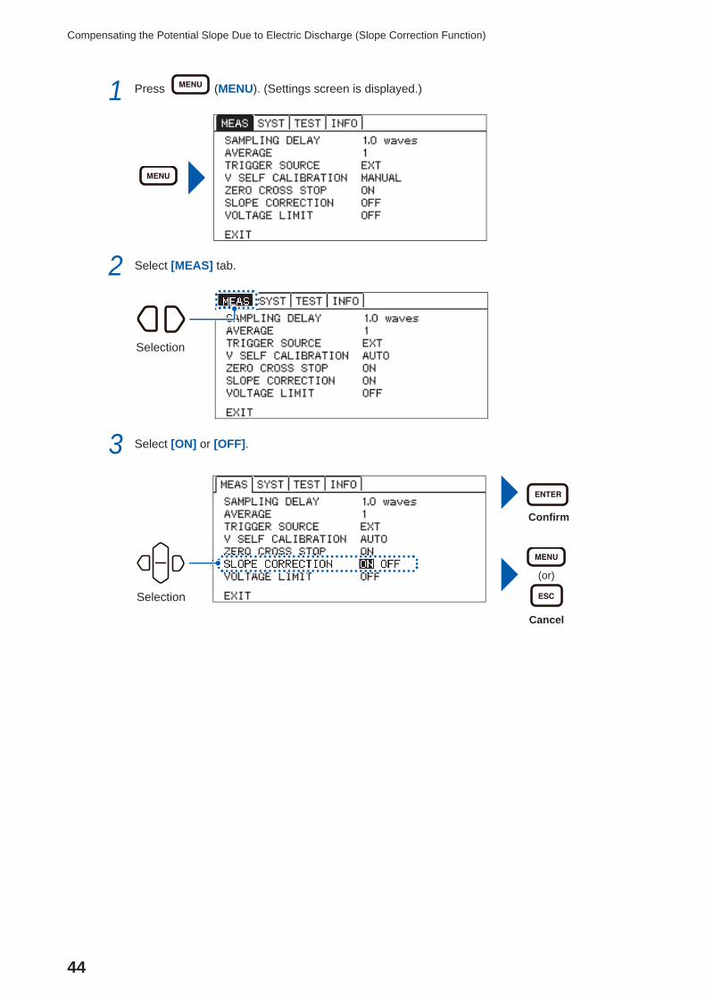
1 Press (MENU). (Settings screen is displayed.)
2 Select [MEAS] tab.
Selection
3 Select [ON] or [OFF].
Confi rm
(or)
Cancel
Selection
45
Preventing the Overcharge due to Measurement Signal (Voltage Limit Function)
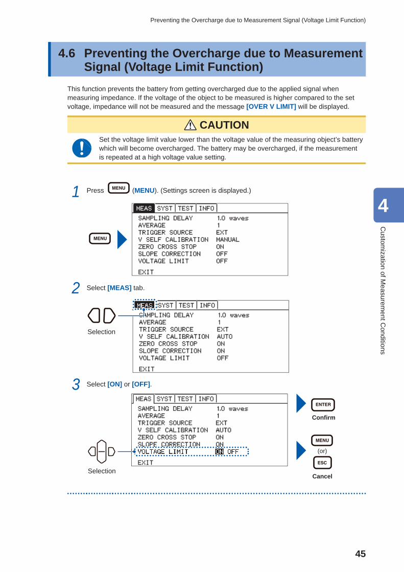
4.6 Preventing the Overcharge due to Measurement Signal ( Voltage Limit Function)
This function prevents the battery from getting overcharged due to the applied signal when measuring impedance. If the voltage of the object to be measured is higher compared to the set voltage, impedance will not be measured and the message [OVER V LIMIT] will be displayed.
CAUTIONSet the voltage limit value lower than the voltage value of the measuring object’s battery which will become overcharged. The battery may be overcharged, if the measurement is repeated at a high voltage value setting.
1 Press (MENU). (Settings screen is displayed.)
2 Select [MEAS] tab.
Selection
3 Select [ON] or [OFF].
Confi rm
(or)
Cancel
Selection
4
Custom
ization of Measurem
ent Conditions
46
Preventing the Overcharge due to Measurement Signal (Voltage Limit Function)
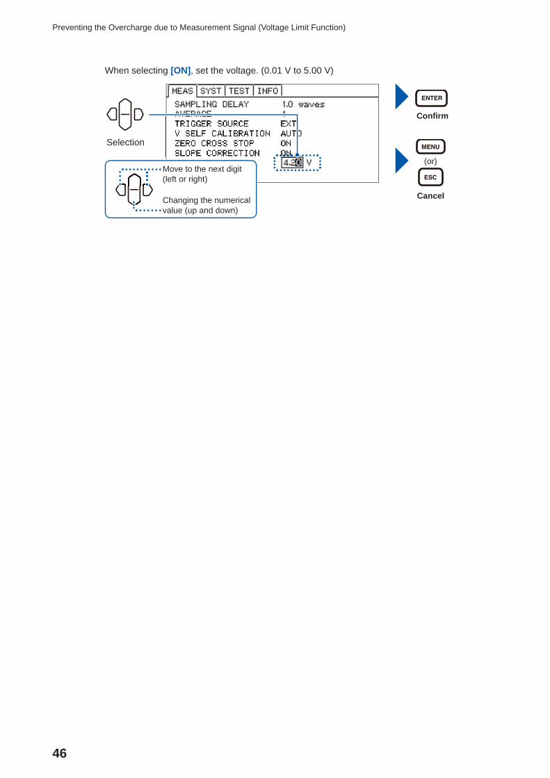
When selecting [ON], set the voltage. (0.01 V to 5.00 V)
Confi rm
(or)
Cancel
Selection
Move to the next digit (left or right)
Changing the numerical value (up and down)
47
Prevents Charging and Discharging due to the Measurement Signal (Measurement Signal Zero Cross Stop Function)
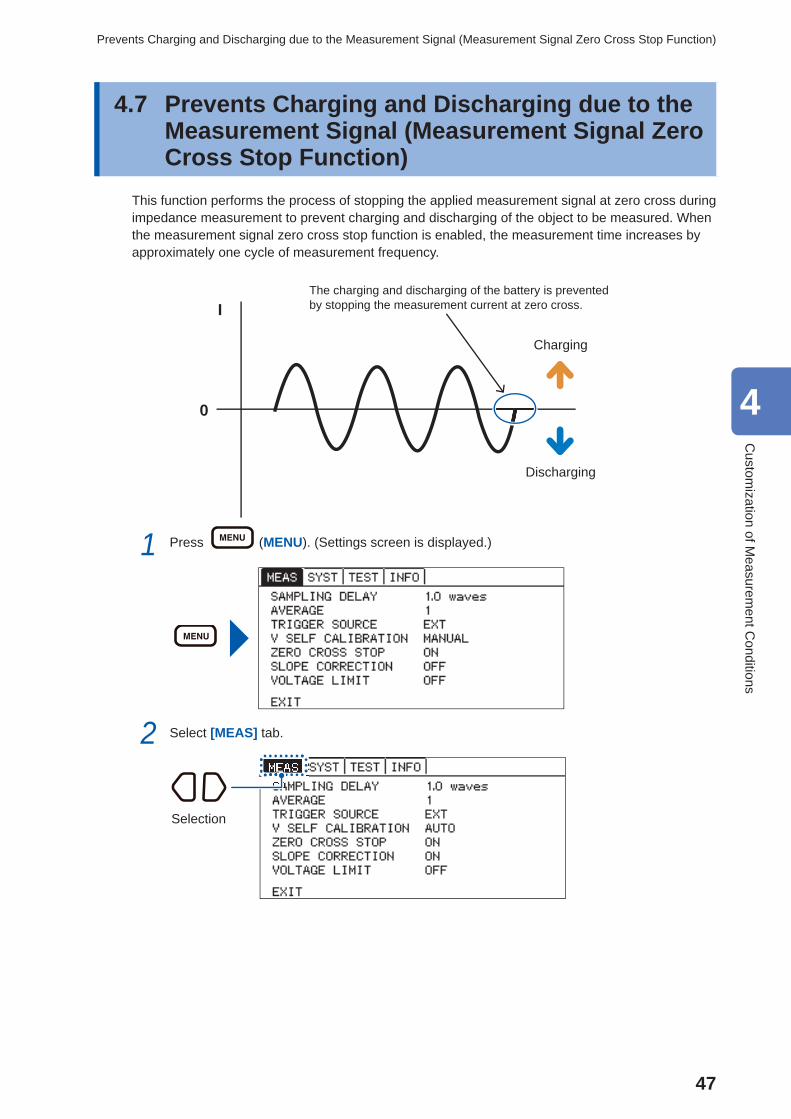
4.7 Prevents Charging and Discharging due to the Measurement Signal (Measurement Signal Zero Cross Stop Function)
This function performs the process of stopping the applied measurement signal at zero cross during impedance measurement to prevent charging and discharging of the object to be measured. When the measurement signal zero cross stop function is enabled, the measurement time increases by approximately one cycle of measurement frequency.
I
0
Charging
Discharging
The charging and discharging of the battery is prevented by stopping the measurement current at zero cross.
1 Press (MENU). (Settings screen is displayed.)
2 Select [MEAS] tab.
Selection
4
Custom
ization of Measurem
ent Conditions
48
Prevents Charging and Discharging due to the Measurement Signal (Measurement Signal Zero Cross Stop Function)
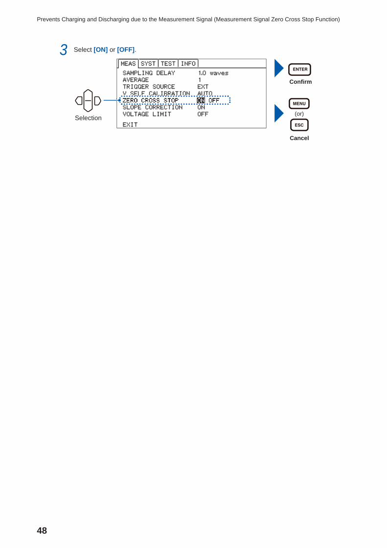
3 Select [ON] or [OFF].
Confi rm
(or)
Cancel
Selection
49
5 Judging Measurement Results (Comparator Function)
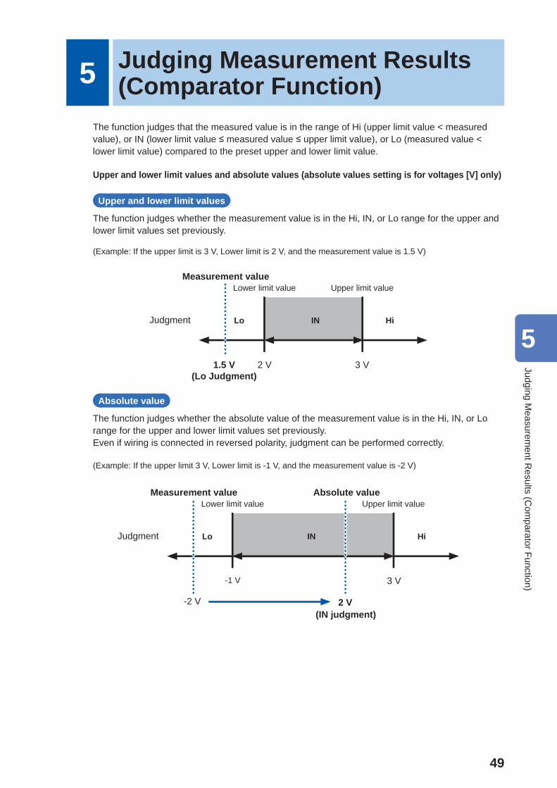
The function judges that the measured value is in the range of Hi (upper limit value < measured value), or IN (lower limit value ≤ measured value ≤ upper limit value), or Lo (measured value < lower limit value) compared to the preset upper and lower limit value.
Upper and lower limit values and absolute values (absolute values setting is for voltages [V] only)
Upper and lower limit values
The function judges whether the measurement value is in the Hi, IN, or Lo range for the upper and lower limit values set previously.
(Example: If the upper limit is 3 V, Lower limit is 2 V, and the measurement value is 1.5 V)
2 V 3 V
Lower limit value Upper limit value
INLoJudgment Hi
1.5 V
Measurement value
(Lo Judgment)
Absolute value
The function judges whether the absolute value of the measurement value is in the Hi, IN, or Lo range for the upper and lower limit values set previously.Even if wiring is connected in reversed polarity, judgment can be performed correctly.
(Example: If the upper limit 3 V, Lower limit is -1 V, and the measurement value is -2 V)
-1 V 3 V
Lower limit value Upper limit value
INLoJudgment Hi
-2 V
Measurement value
2 V(IN judgment)
Absolute value
5
Judging Measurem
ent Results (C
omparator Function)
50
Turning the Comparator Function ON and OFF
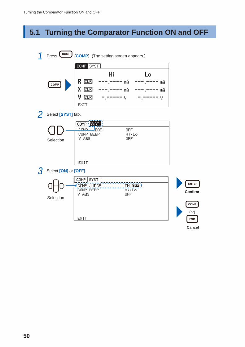
5.1 Turning the Comparator Function ON and OFF
1 Press (COMP). (The setting screen appears.)
2 Select [SYST] tab.
Selection
3 Select [ON] or [OFF].
Confi rm
(or)
Cancel
Selection
51
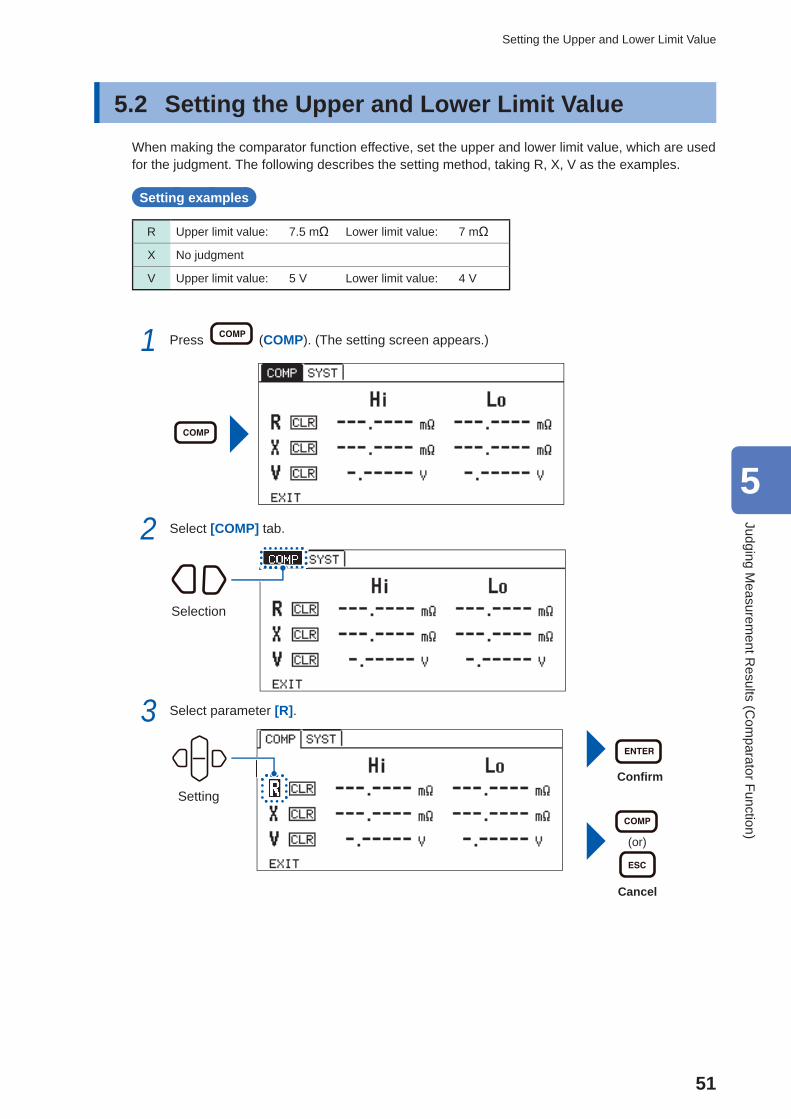
Setting the Upper and Lower Limit Value
5.2 Setting the Upper and Lower Limit ValueWhen making the comparator function effective, set the upper and lower limit value, which are used for the judgment. The following describes the setting method, taking R, X, V as the examples.
Setting examples
R Upper limit value: 7.5 mΩ Lower limit value: 7 mΩ
X No judgment
V Upper limit value: 5 V Lower limit value: 4 V
1 Press (COMP). (The setting screen appears.)
2 Select [COMP] tab.
Selection
3 Select parameter [R].
Confi rm
(or)
Cancel
Setting
5
Judging Measurem
ent Results (C
omparator Function)
52
Setting the Upper and Lower Limit Value
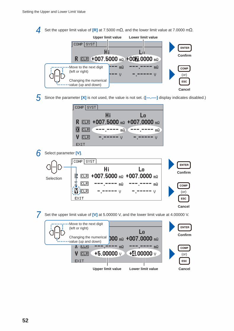
4 Set the upper limit value of [R] at 7.5000 mΩ, and the lower limit value at 7.0000 mΩ.
Confi rm
(or)
Cancel
Upper limit value
Lower limit value
Move to the next digit (left or right)
Changing the numerical value (up and down)
5 Since the parameter [X] is not used, the value is not set. ([---.----] display indicates disabled.)
6 Select parameter [V].
Confi rm
(or)
Cancel
Selection
7 Set the upper limit value of [V] at 5.00000 V, and the lower limit value at 4.00000 V.
Confi rm
(or)
CancelUpper limit value
Lower limit value
Move to the next digit (left or right)
Changing the numerical value (up and down)
53
Setting the Upper and Lower Limit Value
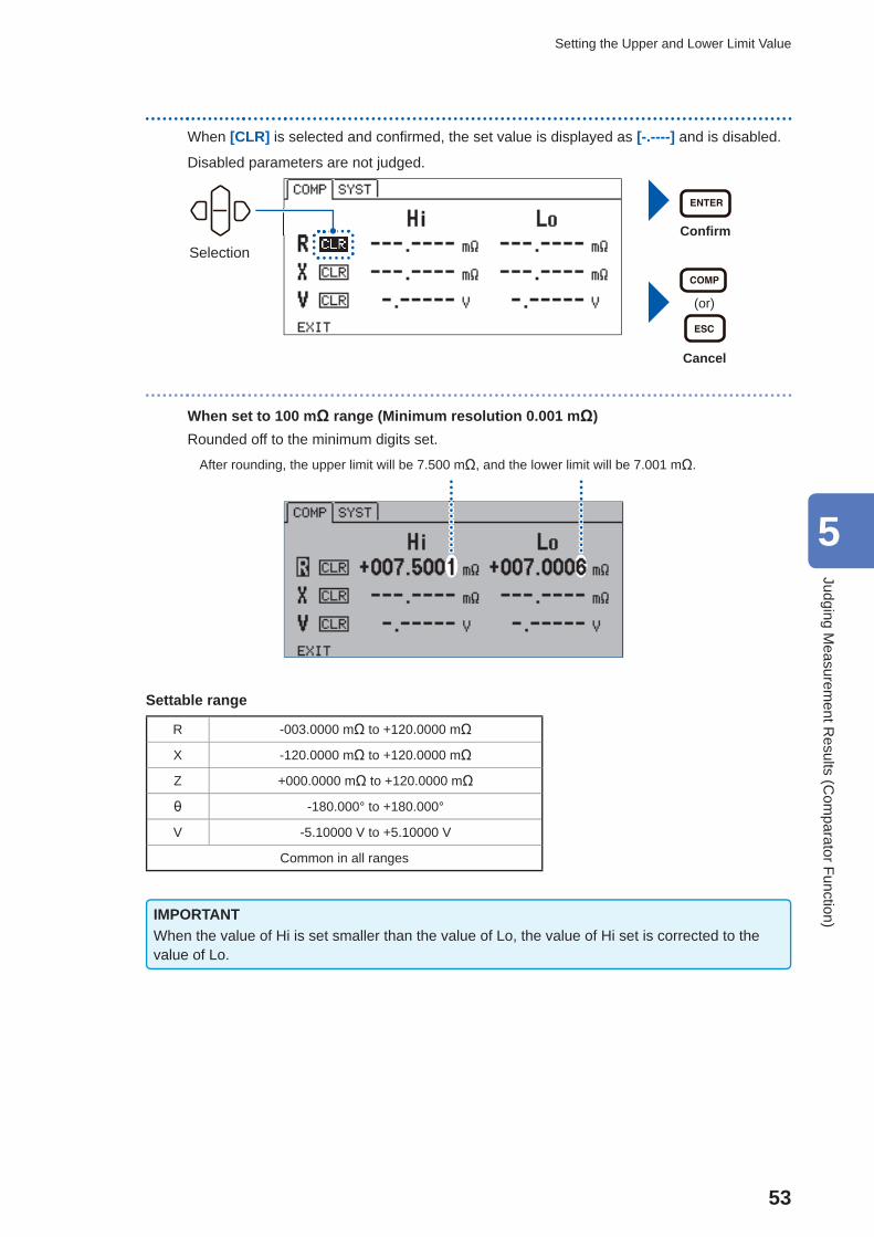
When [CLR] is selected and confi rmed, the set value is displayed as [-.----] and is disabled.
Disabled parameters are not judged.
Confi rm
(or)
Cancel
Selection
When set to 100 mΩ range (Minimum resolution 0.001 mΩ)Rounded off to the minimum digits set.
After rounding, the upper limit will be 7.500 mΩ, and the lower limit will be 7.001 mΩ.
Settable range
R -003.0000 mΩ to +120.0000 mΩ
X -120.0000 mΩ to +120.0000 mΩ
Z +000.0000 mΩ to +120.0000 mΩ
θ -180.000° to +180.000°
V -5.10000 V to +5.10000 V
Common in all ranges
IMPORTANTWhen the value of Hi is set smaller than the value of Lo, the value of Hi set is corrected to the value of Lo.
5
Judging Measurem
ent Results (C
omparator Function)
54
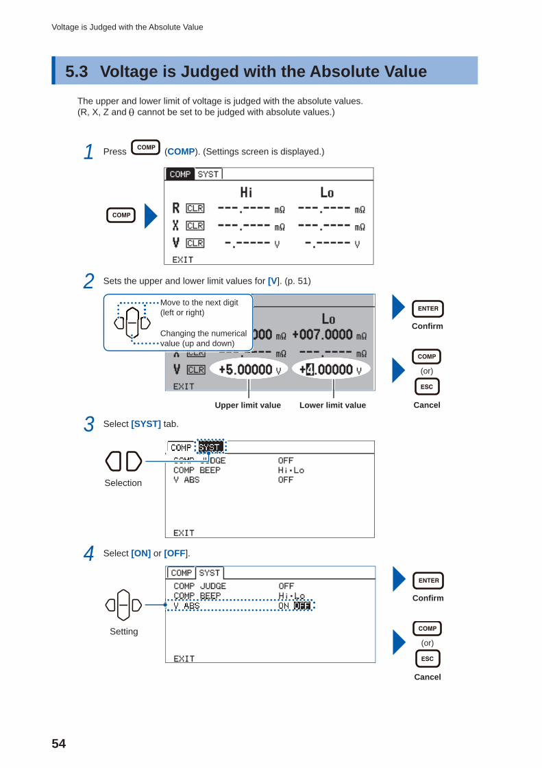
Voltage is Judged with the Absolute Value
5.3 Voltage is Judged with the Absolute ValueThe upper and lower limit of voltage is judged with the absolute values.(R, X, Z and cannot be set to be judged with absolute values.)
1 Press (COMP). (Settings screen is displayed.)
2 Sets the upper and lower limit values for [V]. (p. 51)
Confi rm
(or)
CancelUpper limit value
Lower limit value
Move to the next digit (left or right)
Changing the numerical value (up and down)
3 Select [SYST] tab.
Selection
4 Select [ON] or [OFF].
Setting
Confi rm
(or)
Cancel
55
Checking the Judgment with Sound
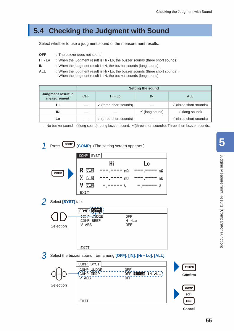
5.4 Checking the Judgment with Sound Select whether to use a judgment sound of the measurement results.
OFF : The buzzer does not sound.Hi • Lo : When the judgment result is Hi • Lo, the buzzer sounds (three short sounds).IN : When the judgment result is IN, the buzzer sounds (long sound).ALL : When the judgment result is Hi • Lo, the buzzer sounds (three short sounds).
When the judgment result is IN, the buzzer sounds (long sound).
Setting the soundJudgment result in
measurement OFF Hi • Lo IN ALL
HI — (three short sounds) — (three short sounds)
IN — — (long sound) (long sound)
Lo — (three short sounds) — (three short sounds)
—: No buzzer sound, (long sound): Long buzzer sound, (three short sounds): Three short buzzer sounds.
1 Press (COMP). (The setting screen appears.)
2 Select [SYST] tab.
Selection
3 Select the buzzer sound from among [OFF], [IN], [Hi • Lo], [ALL].
Selection
Confi rm
(or)
Cancel
5
Judging Measurem
ent Results (C
omparator Function)
56
Checking the Judgment Result
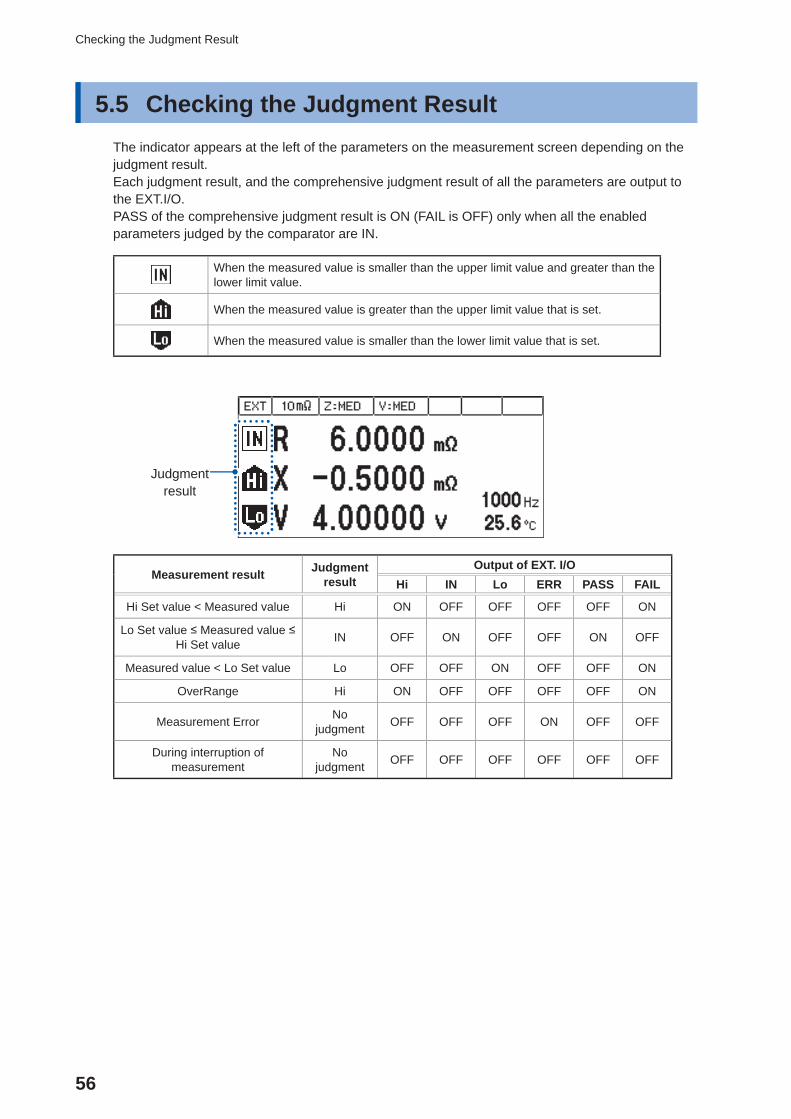
5.5 Checking the Judgment ResultThe indicator appears at the left of the parameters on the measurement screen depending on the judgment result.Each judgment result, and the comprehensive judgment result of all the parameters are output to the EXT.I/O.PASS of the comprehensive judgment result is ON (FAIL is OFF) only when all the enabled parameters judged by the comparator are IN.
When the measured value is smaller than the upper limit value and greater than the lower limit value.
When the measured value is greater than the upper limit value that is set.
When the measured value is smaller than the lower limit value that is set.
Judgment result
t
Measurement result Judgment result
Output of EXT. I/OHi IN Lo ERR PASS FAIL
Hi Set value < Measured value Hi ON OFF OFF OFF OFF ON
Lo Set value ≤ Measured value ≤ Hi Set value IN OFF ON OFF OFF ON OFF
Measured value < Lo Set value Lo OFF OFF ON OFF OFF ON
OverRange Hi ON OFF OFF OFF OFF ON
Measurement Error No judgment OFF OFF OFF ON OFF OFF
During interruption of measurement
No judgment OFF OFF OFF OFF OFF OFF
57
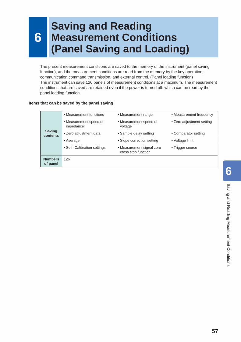
6Saving and Reading Measurement Conditions(Panel Saving and Loading)
The present measurement conditions are saved to the memory of the instrument (panel saving function), and the measurement conditions are read from the memory by the key operation, communication command transmission, and external control. (Panel loading function)The instrument can save 126 panels of measurement conditions at a maximum. The measurement conditions that are saved are retained even if the power is turned off, which can be read by the panel loading function.
Items that can be saved by the panel saving
Saving contents
• Measurement functions • Measurement range • Measurement frequency
• Measurement speed of impedance
• Measurement speed of voltage
• Zero adjustment setting
• Zero adjustment data • Sample delay setting • Comparator setting
• Average • Slope correction setting • Voltage limit
• Self -Calibration settings • Measurement signal zero cross stop function
• Trigger source
Numbers of panel
126
6
Saving and R
eading Measurem
ent Conditions
58
Saving the Setting Conditions (Panel Saving Function)
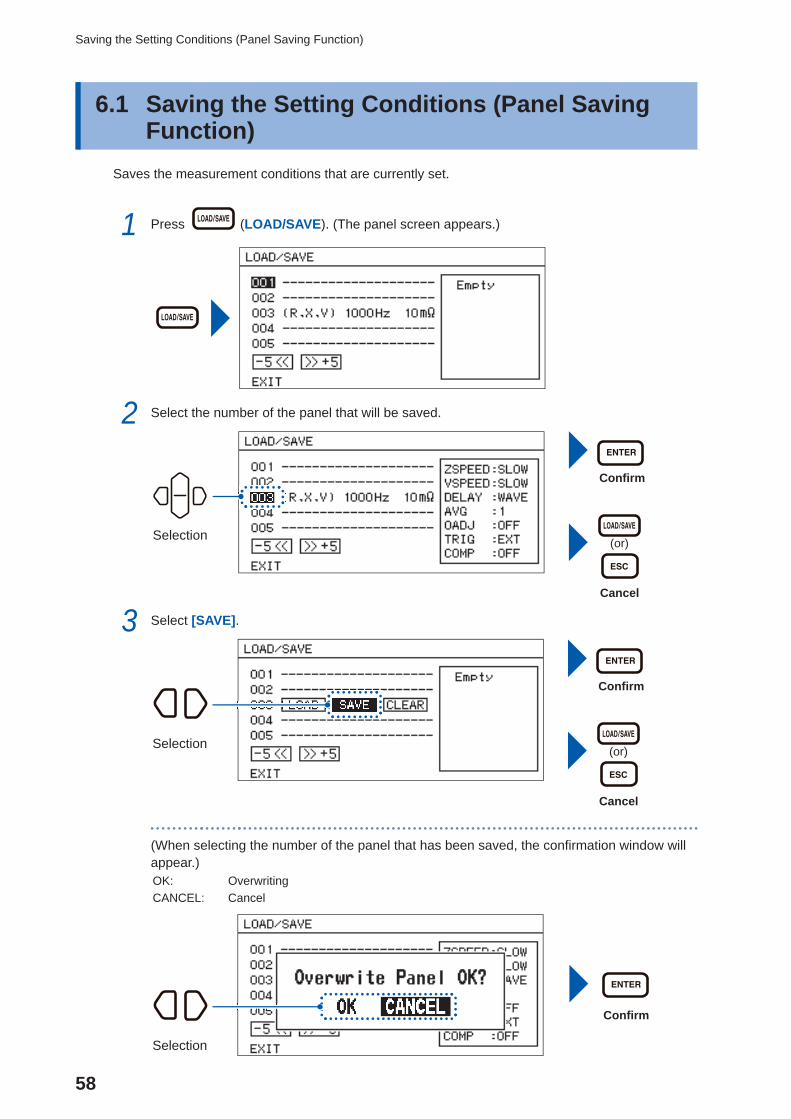
6.1 Saving the Setting Conditions ( Panel Saving Function)
Saves the measurement conditions that are currently set.
1 Press (LOAD/SAVE). (The panel screen appears.)
2 Select the number of the panel that will be saved.
Confi rm
(or)
Cancel
Selection
3 Select [SAVE].
Confi rm
(or)
Cancel
Selection
(When selecting the number of the panel that has been saved, the confi rmation window will appear.)OK: OverwritingCANCEL: Cancel
Confi rm
Selection
59
Saving the Setting Conditions (Panel Saving Function)
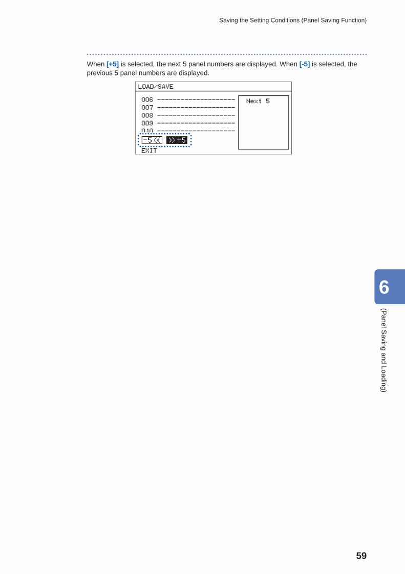
When [+5] is selected, the next 5 panel numbers are displayed. When [-5] is selected, the previous 5 panel numbers are displayed.
6
(Panel S
aving and Loading)
60
Reading the Setting Conditions (Panel Loading Function)
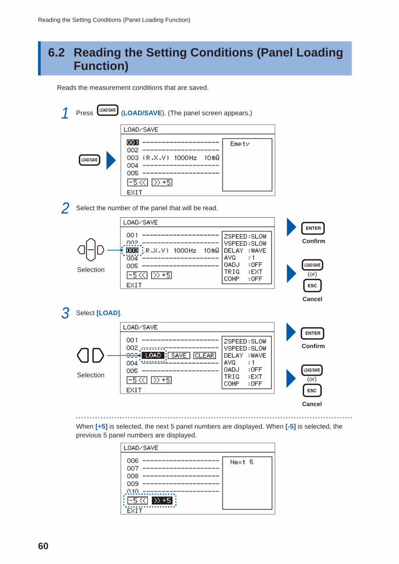
6.2 Reading the Setting Conditions ( Panel Loading Function)
Reads the measurement conditions that are saved.
1 Press (LOAD/SAVE). (The panel screen appears.)
2 Select the number of the panel that will be read.
Confi rm
(or)
Cancel
Selection
3 Select [LOAD].
Confi rm
(or)
Cancel
Selection
When [+5] is selected, the next 5 panel numbers are displayed. When [-5] is selected, the previous 5 panel numbers are displayed.
61
Deleting the Contents of the Panel
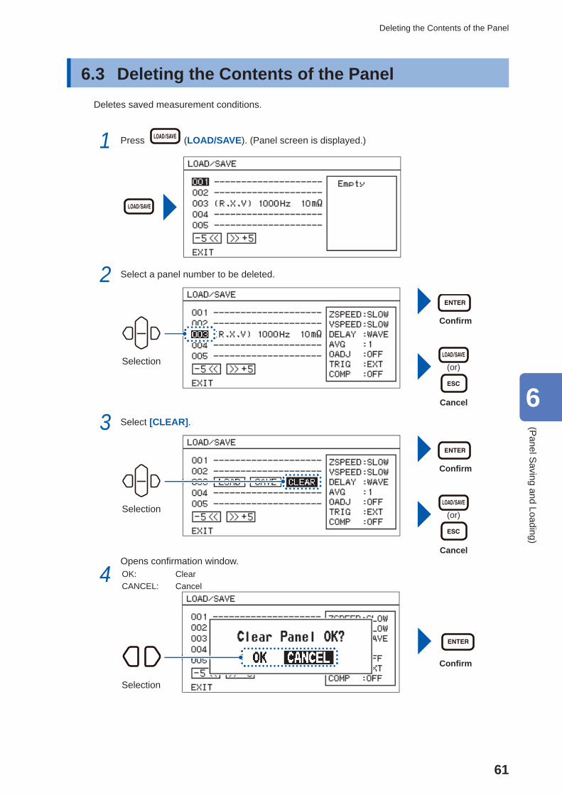
6.3 Deleting the Contents of the Panel Deletes saved measurement conditions.
1 Press (LOAD/SAVE). (Panel screen is displayed.)
2 Select a panel number to be deleted.
Confi rm
(or)
Cancel
Selection
3 Select [CLEAR].
Confi rm
(or)
Cancel
Selection
4 Opens confi rmation window.OK: ClearCANCEL: Cancel
Confi rm
Selection
6
(Panel S
aving and Loading)

62
Deleting the Contents of the Panel
63
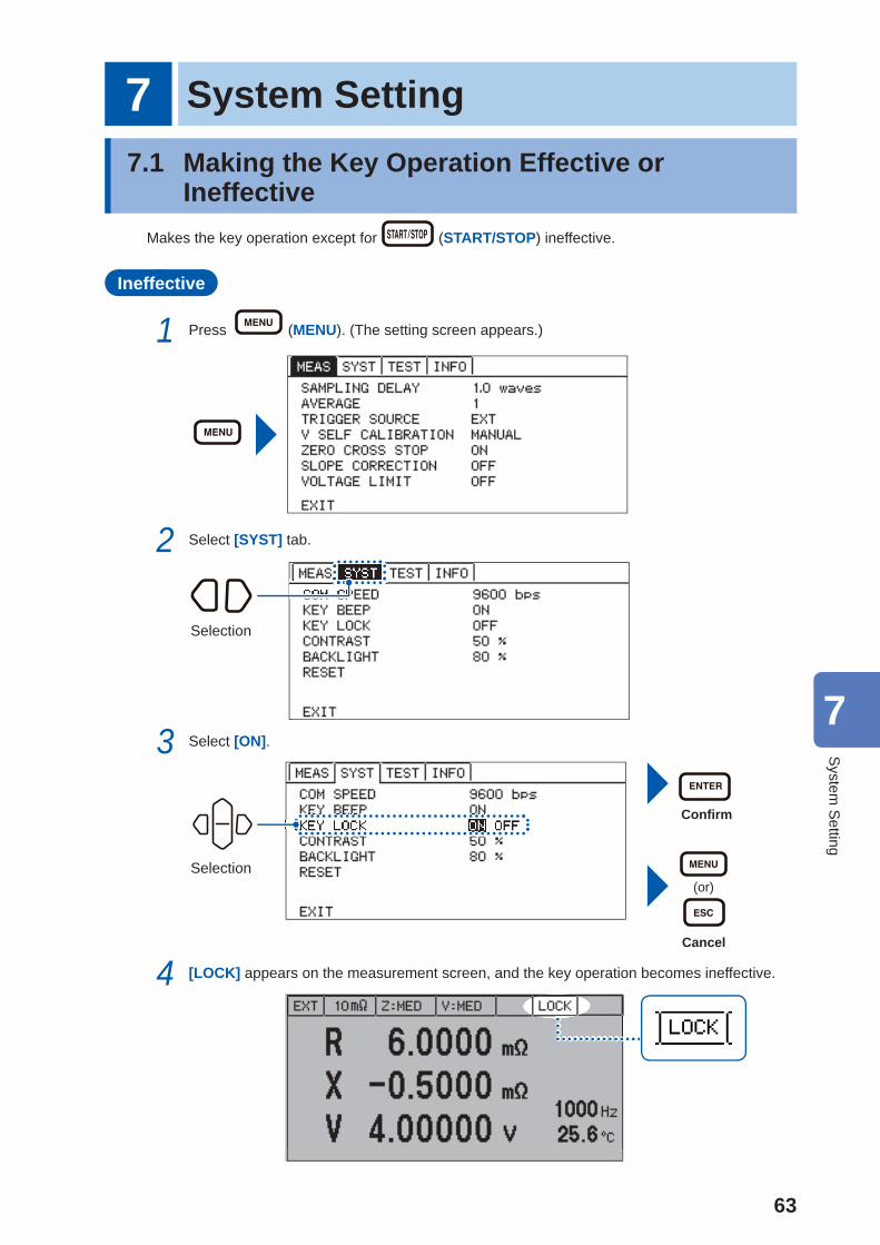
7 System Setting7.1 Making the Key Operation Effective or
IneffectiveMakes the key operation except for (START/STOP) ineffective.
Ineffective
1 Press (MENU). (The setting screen appears.)
2 Select [SYST] tab.
Selection
3 Select [ON].
Confi rm
(or)
Cancel
Selection
4 [LOCK] appears on the measurement screen, and the key operation becomes ineffective.
7
System
Setting
64
Making the Key Operation Effective or Ineffective
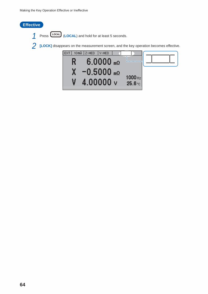
Effective
1 Press (LOCAL) and hold for at least 5 seconds.
2 [LOCK] disappears on the measurement screen, and the key operation becomes effective.
65
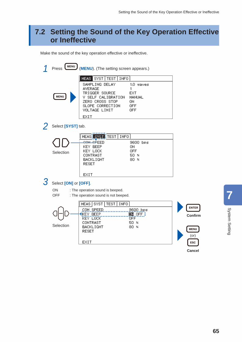
Setting the Sound of the Key Operation Effective or Ineffective
7.2 Setting the Sound of the Key Operation Effective or Ineffective
Make the sound of the key operation effective or ineffective.
1 Press (MENU). (The setting screen appears.)
2 Select [SYST] tab.
Selection
3 Select [ON] or [OFF].ON : The operation sound is beeped.OFF : The operation sound is not beeped.
Confi rm
(or)
Cancel
Selection
7
System
Setting
66
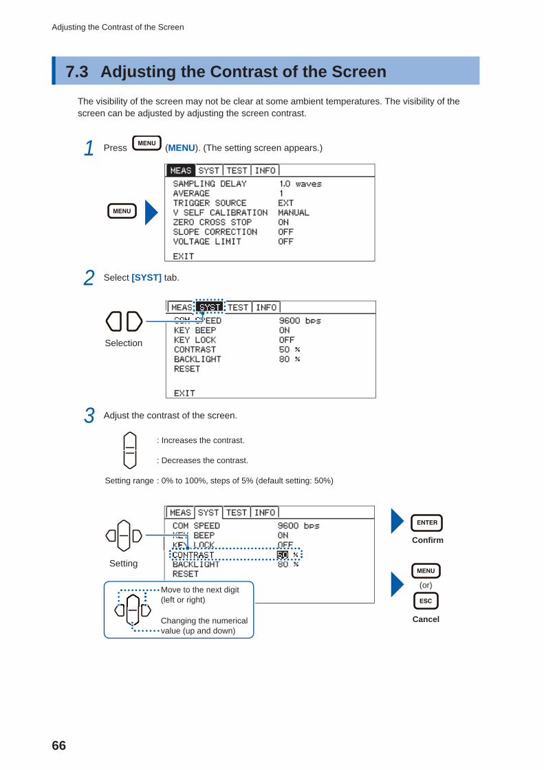
Adjusting the Contrast of the Screen
7.3 Adjusting the Contrast of the ScreenThe visibility of the screen may not be clear at some ambient temperatures. The visibility of the screen can be adjusted by adjusting the screen contrast.
1 Press (MENU). (The setting screen appears.)
2 Select [SYST] tab.
Selection
3 Adjust the contrast of the screen.
: Increases the contrast.
: Decreases the contrast.
Setting range : 0% to 100%, steps of 5% (default setting: 50%)
Confi rm
(or)
Cancel
Setting
Move to the next digit (left or right)
Changing the numerical value (up and down)
67
Adjusting the Backlight
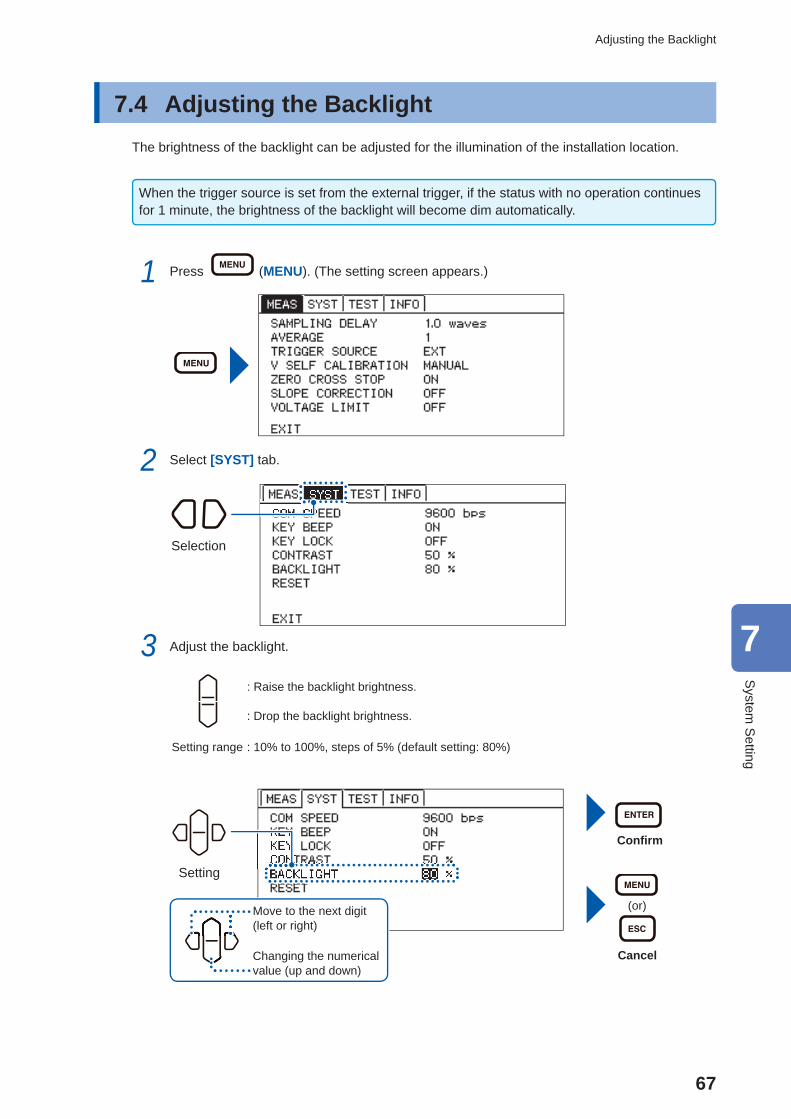
7.4 Adjusting the BacklightThe brightness of the backlight can be adjusted for the illumination of the installation location.
When the trigger source is set from the external trigger, if the status with no operation continues for 1 minute, the brightness of the backlight will become dim automatically.
1 Press (MENU). (The setting screen appears.)
2 Select [SYST] tab.
Selection
3 Adjust the backlight.
: Raise the backlight brightness.
: Drop the backlight brightness.
Setting range : 10% to 100%, steps of 5% (default setting: 80%)
Confi rm
(or)
Cancel
Setting
Move to the next digit (left or right)
Changing the numerical value (up and down)
7
System
Setting
68
System Testing
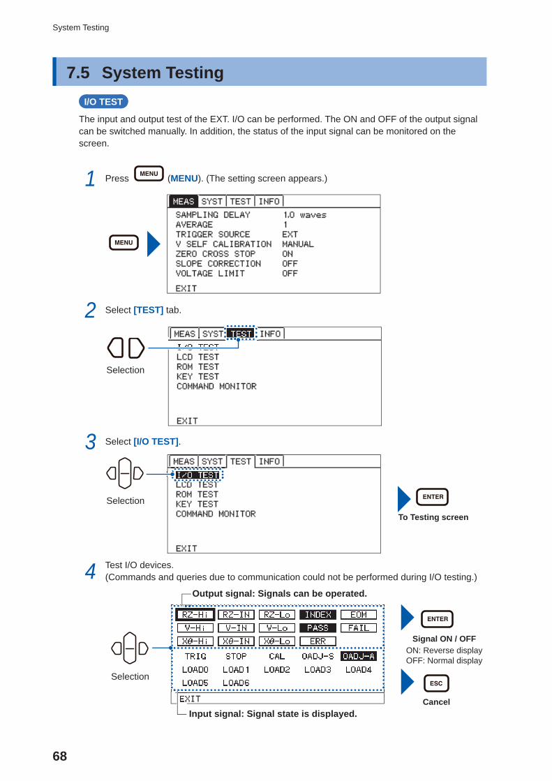
7.5 System Testing I/O TEST
The input and output test of the EXT. I/O can be performed. The ON and OFF of the output signal can be switched manually. In addition, the status of the input signal can be monitored on the screen.
1 Press (MENU). (The setting screen appears.)
2 Select [TEST] tab.
Selection
3 Select [I/O TEST].
Selection
To Testing screen
4 Test I/O devices.(Commands and queries due to communication could not be performed during I/O testing.)
Selection
Signal ON / OFFON: Reverse displayOFF: Normal display
Cancel
Output signal: Signals can be operated.
Input signal: Signal state is displayed.
69
System Testing
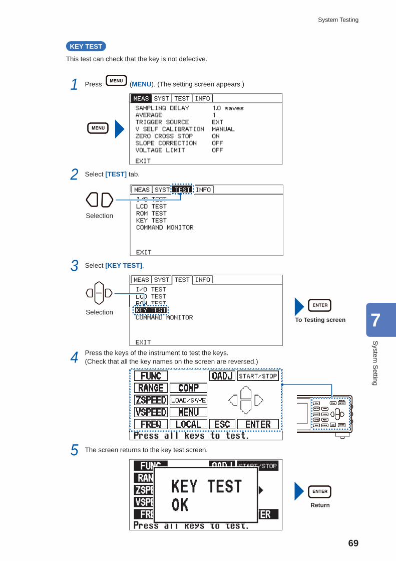
KEY TEST
This test can check that the key is not defective.
1 Press (MENU). (The setting screen appears.)
2 Select [TEST] tab.
Selection
3 Select [KEY TEST].
SelectionTo Testing screen
4 Press the keys of the instrument to test the keys.(Check that all the key names on the screen are reversed.)
5 The screen returns to the key test screen.
Return
7
System
Setting
70
System Testing
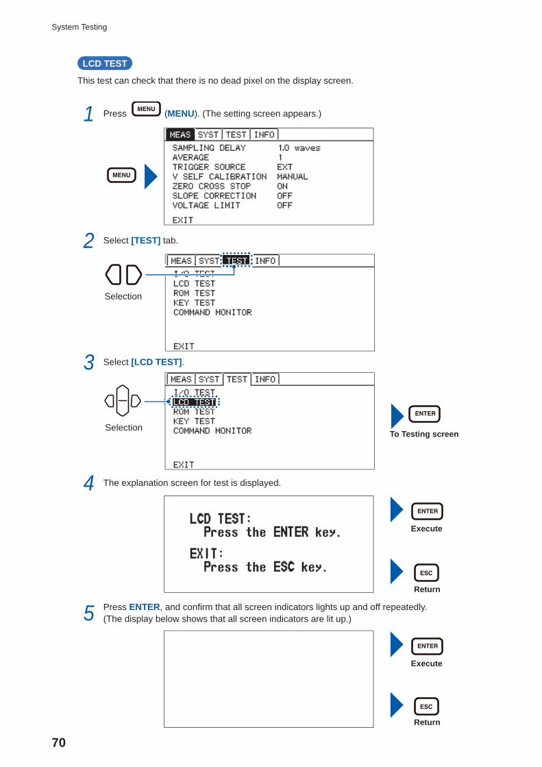
LCD TEST
This test can check that there is no dead pixel on the display screen.
1 Press (MENU). (The setting screen appears.)
2 Select [TEST] tab.
Selection
3 Select [LCD TEST].
SelectionTo Testing screen
4 The explanation screen for test is displayed.
Execute
Return
5 Press ENTER, and confi rm that all screen indicators lights up and off repeatedly.(The display below shows that all screen indicators are lit up.)
Execute
Return
71
System Testing
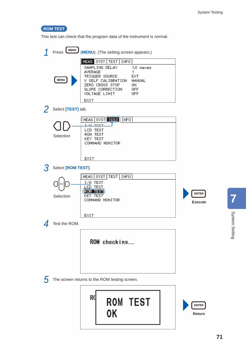
ROM TEST
This test can check that the program data of the instrument is normal.
1 Press (MENU). (The setting screen appears.)
2 Select [TEST] tab.
Selection
3 Select [ROM TEST].
SelectionExecute
4 Test the ROM.
5 The screen returns to the ROM testing screen.
Return
7
System
Setting
72
System Testing
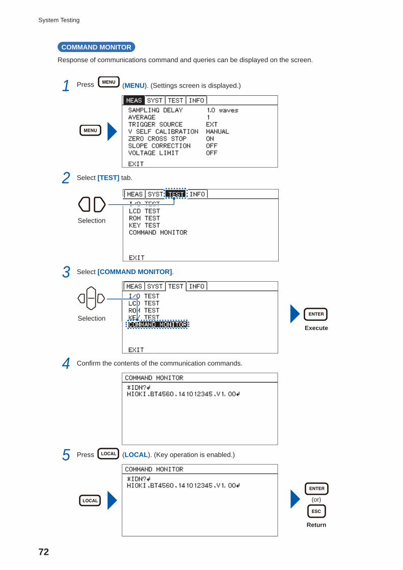
COMMAND MONITOR
Response of communications command and queries can be displayed on the screen.
1 Press (MENU). (Settings screen is displayed.)
2 Select [TEST] tab.
Selection
3 Select [COMMAND MONITOR].
SelectionExecute
4 Confi rm the contents of the communication commands.
5 Press (LOCAL). (Key operation is enabled.)
(or)
Return
73
Confi rm Instrument Information
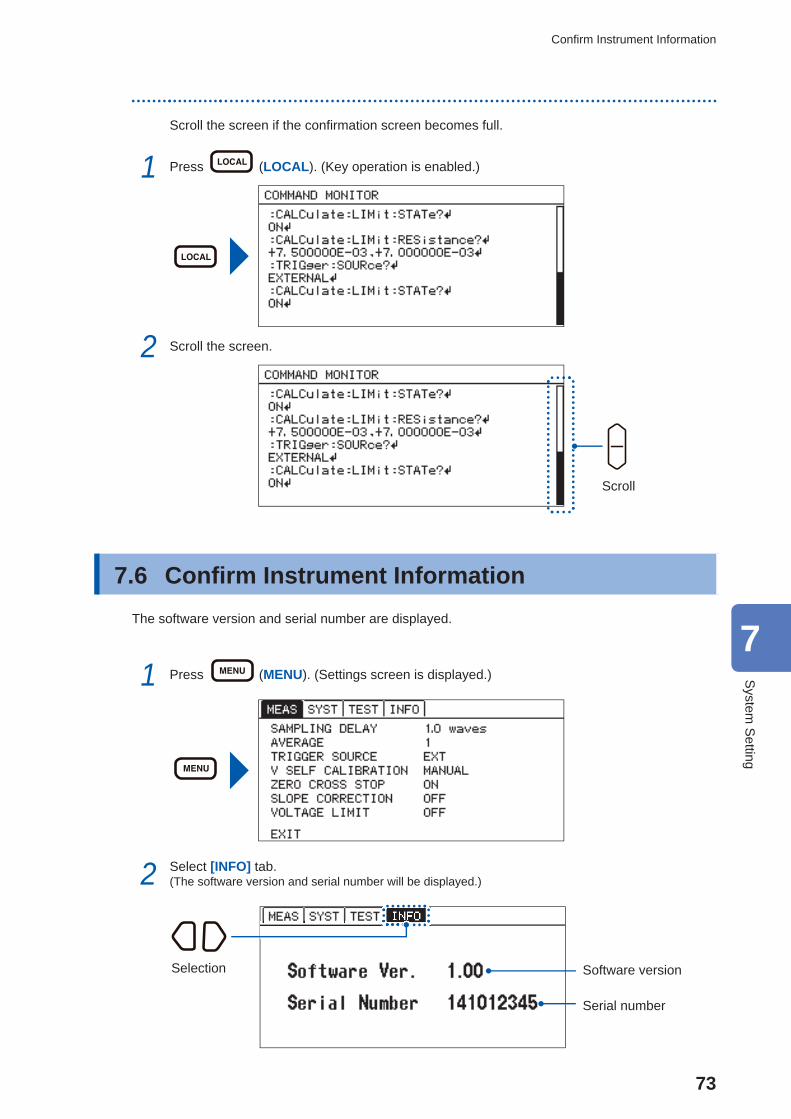
Scroll the screen if the confi rmation screen becomes full.
1 Press (LOCAL). (Key operation is enabled.)
2 Scroll the screen.
Scroll
7.6 Confi rm Instrument InformationThe software version and serial number are displayed.
1 Press (MENU). (Settings screen is displayed.)
2 Select [INFO] tab.(The software version and serial number will be displayed.)
Selection Software version
Serial number
7
System
Setting
74
Initializing (Reset)
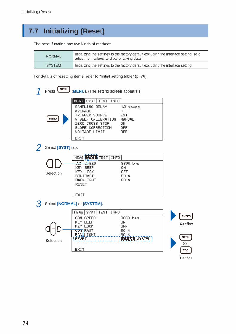
7.7 Initializing ( Reset)The reset function has two kinds of methods.
NORMAL Initializing the settings to the factory default excluding the interface setting, zero adjustment values, and panel saving data.
SYSTEM Initializing the settings to the factory default excluding the interface setting.
For details of resetting items, refer to “Initial setting table” (p. 76).
1 Press (MENU). (The setting screen appears.)
2 Select [SYST] tab.
Selection
3 Select [NORMAL] or [SYSTEM].
Confi rm
(or)
Cancel
Selection
75
Initializing (Reset)
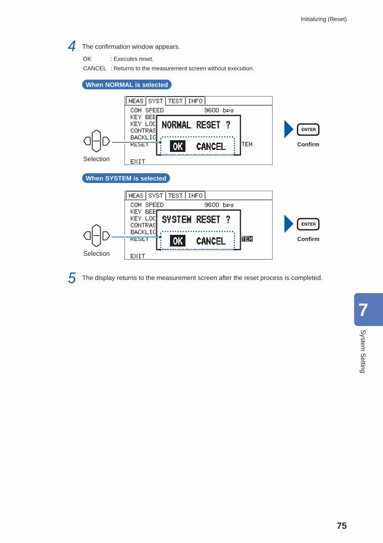
4 The confi rmation window appears.
OK : Executes reset.CANCEL : Returns to the measurement screen without execution.
When NORMAL is selected
Selection
Confi rm
When SYSTEM is selected
Selection
Confi rm
5 The display returns to the measurement screen after the reset process is completed.
7
System
Setting
76
Initializing (Reset)
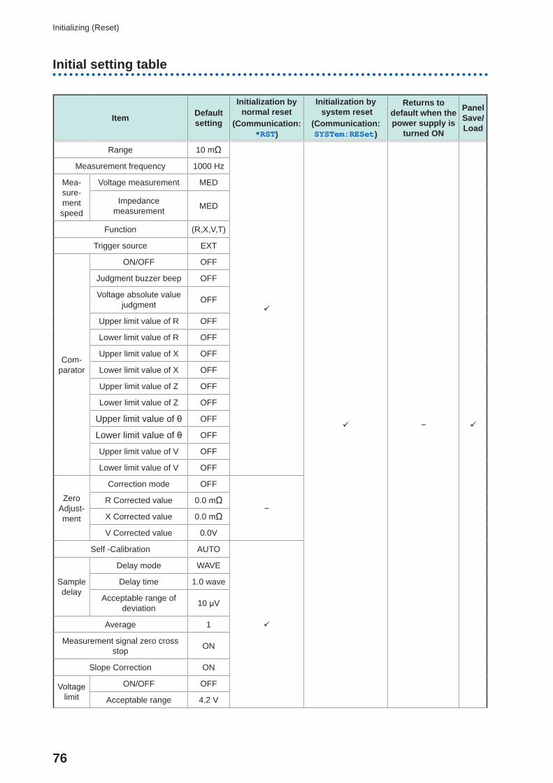
Initial setting table
Item Default setting
Initialization by normal reset
(Communication: *RST)
Initialization by system reset
(Communication: SYSTem:RESet)
Returns to default when the power supply is
turned ON
Panel Save/ Load
Range 10 mΩ
−
Measurement frequency 1000 Hz
Mea-sure-ment speed
Voltage measurement MED
Impedance measurement MED
Function (R,X,V,T)
Trigger source EXT
Com-parator
ON/OFF OFF
Judgment buzzer beep OFF
Voltage absolute value judgment OFF
Upper limit value of R OFF
Lower limit value of R OFF
Upper limit value of X OFF
Lower limit value of X OFF
Upper limit value of Z OFF
Lower limit value of Z OFF
Upper limit value of θ OFF
Lower limit value of θ OFF
Upper limit value of V OFF
Lower limit value of V OFF
Zero Adjust-ment
Correction mode OFF
−R Corrected value 0.0 mΩ
X Corrected value 0.0 mΩ
V Corrected value 0.0V
Self -Calibration AUTO
Sample delay
Delay mode WAVE
Delay time 1.0 wave
Acceptable range of deviation 10 μV
Average 1
Measurement signal zero cross stop ON
Slope Correction ON
Voltage limit
ON/OFF OFF
Acceptable range 4.2 V
77
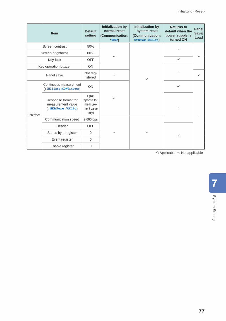
Initializing (Reset)
Item Default setting
Initialization by normal reset
(Communication: *RST)
Initialization by system reset
(Communication: SYSTem:RESet)
Returns to default when the power supply is
turned ON
Panel Save/ Load
Screen contrast 50%
−
−Screen brightness 80%
Key-lock OFF
Key operation buzzer ON−
Panel save Not reg-istered −
Interface
Continuous measurement(:INITiate:CONTinuous) ON
−
Response format for measurement value(:MEASure:VALid)
1 (Re-sponse for measure-
ment value only)
-
Communication speed 9,600 bps
− −
Header OFF
Status byte register 0
Event register 0
Enable register 0
: Applicable, −: Not applicable
7
System
Setting

78
Initializing (Reset)
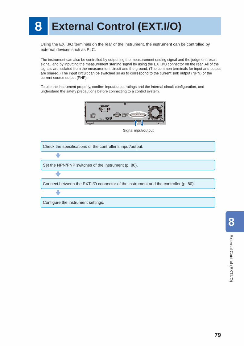
79
8 External Control (EXT.I/O)Using the EXT.I/O terminals on the rear of the instrument, the instrument can be controlled by external devices such as PLC.
The instrument can also be controlled by outputting the measurement ending signal and the judgment result signal, and by inputting the measurement starting signal by using the EXT.I/O connector on the rear. All of the signals are isolated from the measurement circuit and the ground. (The common terminals for input and output are shared.) The input circuit can be switched so as to correspond to the current sink output (NPN) or the current source output (PNP).
To use the instrument properly, confi rm input/output ratings and the internal circuit confi guration, and understand the safety precautions before connecting to a control system.
Signal input/output
Check the specifi cations of the controller’s input/output.
Set the NPN/PNP switches of the instrument (p. 80).
Connect between the EXT.I/O connector of the instrument and the controller (p. 80).
Confi gure the instrument settings.
8
External C
ontrol (EX
T.I/O)
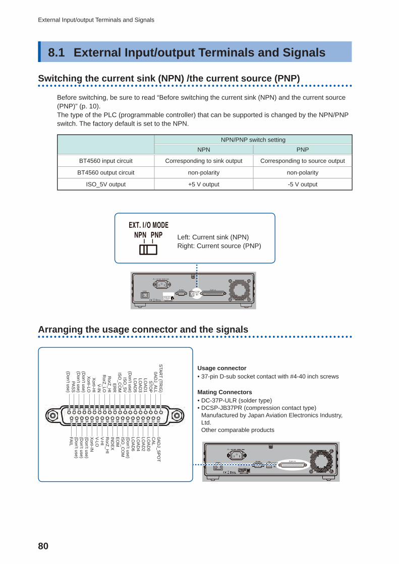
80
External Input/output Terminals and Signals
8.1 External Input/output Terminals and Signals
Switching the current sink (NPN) / the current source (PNP)
Before switching, be sure to read “Before switching the current sink (NPN) and the current source (PNP)” (p. 10).The type of the PLC (programmable controller) that can be supported is changed by the NPN/PNP switch. The factory default is set to the NPN.
NPN/PNP switch settingNPN PNP
BT4560 input circuit Corresponding to sink output Corresponding to source output
BT4560 output circuit non-polarity non-polarity
ISO_5V output +5 V output -5 V output
Left: Current sink (NPN)Right: Current source (PNP)
Arranging the usage connector and the signals
Usage connector • 37-pin D-sub socket contact with #4-40 inch screws
Mating Connectors • DC-37P-ULR (solder type) • DCSP-JB37PR (compression contact type)Manufactured by Japan Aviation Electronics Industry, Ltd.Other comparable products
2 14 36 58 79
202122232425262728293031323334353637
141516171819 10111213
STA
RT (TR
IG)
0AD
J_ALL
STO
PLO
AD
1LO
AD
3LO
AD
5(D
on’t use)IS
O_5V
ISO
_CO
ME
RR
RorZ_H
IR
orZ_LOV-IN
Xor -H
IX
or -LO(D
on’t use)(D
on’t use)PA
SS
(Don’t use)
373377 363336 35555 3433444 33333 323222 31331 3000000 299999 2822888 277777 2626666 2555555 244444 232333 22222 21222 202220
0AD
J_SP
OT
CA
LLO
AD
0LO
AD
2LO
AD
4LO
AD
6(D
on’t use)IS
O_C
OM
EO
MIN
DE
XR
orZ_HI
V-HI
V-LOX
or -IN(D
on’t use)(D
on’t use)(D
on’t use)FA
IL
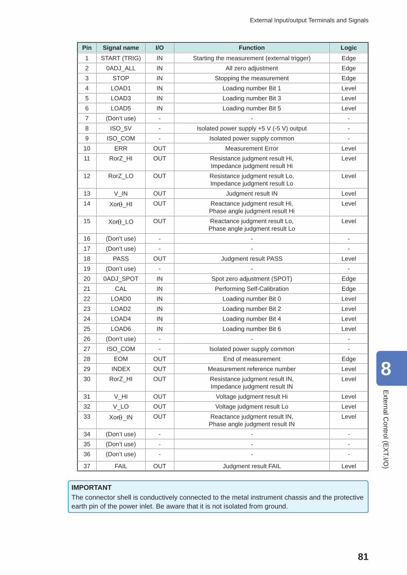
81
External Input/output Terminals and Signals
Pin Signal name I/O Function Logic1 START (TRIG) IN Starting the measurement (external trigger) Edge2 0ADJ_ALL IN All zero adjustment Edge3 STOP IN Stopping the measurement Edge4 LOAD1 IN Loading number Bit 1 Level5 LOAD3 IN Loading number Bit 3 Level6 LOAD5 IN Loading number Bit 5 Level7 (Don’t use) - - -8 ISO_5V - Isolated power supply +5 V (-5 V) output -9 ISO_COM - Isolated power supply common -
10 ERR OUT Measurement Error Level11 RorZ_HI OUT Resistance judgment result Hi,
Impedance judgment result HiLevel
12 RorZ_LO OUT Resistance judgment result Lo, Impedance judgment result Lo
Level
13 V_IN OUT Judgment result IN Level14 Xor_HI OUT Reactance judgment result Hi,
Phase angle judgment result HiLevel
15 Xor_LO OUT Reactance judgment result Lo, Phase angle judgment result Lo
Level
16 (Don’t use) - - -17 (Don’t use) - - -18 PASS OUT Judgment result PASS Level19 (Don’t use) - - -20 0ADJ_SPOT IN Spot zero adjustment (SPOT) Edge21 CAL IN Performing Self-Calibration Edge22 LOAD0 IN Loading number Bit 0 Level23 LOAD2 IN Loading number Bit 2 Level24 LOAD4 IN Loading number Bit 4 Level25 LOAD6 IN Loading number Bit 6 Level26 (Don’t use) - - -27 ISO_COM - Isolated power supply common -28 EOM OUT End of measurement Edge29 INDEX OUT Measurement reference number Level30 RorZ_HI OUT Resistance judgment result IN,
Impedance judgment result INLevel
31 V_HI OUT Voltage judgment result Hi Level32 V_LO OUT Voltage judgment result Lo Level33 Xor_IN OUT Reactance judgment result IN,
Phase angle judgment result INLevel
34 (Don’t use) - - -35 (Don’t use) - - -36 (Don’t use) - - -
37 FAIL OUT Judgment result FAIL Level
IMPORTANTThe connector shell is conductively connected to the metal instrument chassis and the protective earth pin of the power inlet. Be aware that it is not isolated from ground.
8
External C
ontrol (EX
T.I/O)
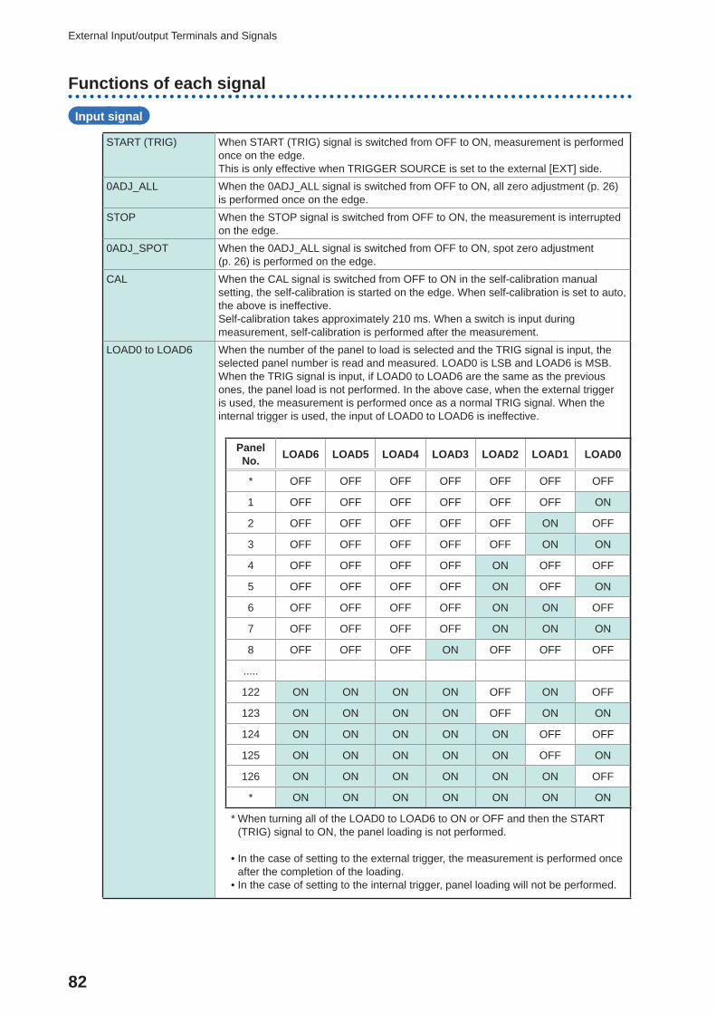
82
External Input/output Terminals and Signals
Functions of each signal
Input signal
START (TRIG) When START (TRIG) signal is switched from OFF to ON, measurement is performed once on the edge. This is only effective when TRIGGER SOURCE is set to the external [EXT] side.
0ADJ_ALL When the 0ADJ_ALL signal is switched from OFF to ON, all zero adjustment (p. 26) is performed once on the edge.
STOP When the STOP signal is switched from OFF to ON, the measurement is interrupted on the edge.
0ADJ_SPOT When the 0ADJ_ALL signal is switched from OFF to ON, spot zero adjustment (p. 26) is performed on the edge.
CAL When the CAL signal is switched from OFF to ON in the self-calibration manual setting, the self-calibration is started on the edge. When self-calibration is set to auto, the above is ineffective. Self-calibration takes approximately 210 ms. When a switch is input during measurement, self-calibration is performed after the measurement.
LOAD0 to LOAD6 When the number of the panel to load is selected and the TRIG signal is input, the selected panel number is read and measured. LOAD0 is LSB and LOAD6 is MSB. When the TRIG signal is input, if LOAD0 to LOAD6 are the same as the previous ones, the panel load is not performed. In the above case, when the external trigger is used, the measurement is performed once as a normal TRIG signal. When the internal trigger is used, the input of LOAD0 to LOAD6 is ineffective.
Panel No. LOAD6 LOAD5 LOAD4 LOAD3 LOAD2 LOAD1 LOAD0
* OFF OFF OFF OFF OFF OFF OFF
1 OFF OFF OFF OFF OFF OFF ON
2 OFF OFF OFF OFF OFF ON OFF
3 OFF OFF OFF OFF OFF ON ON
4 OFF OFF OFF OFF ON OFF OFF
5 OFF OFF OFF OFF ON OFF ON
6 OFF OFF OFF OFF ON ON OFF
7 OFF OFF OFF OFF ON ON ON
8 OFF OFF OFF ON OFF OFF OFF
.....
122 ON ON ON ON OFF ON OFF
123 ON ON ON ON OFF ON ON
124 ON ON ON ON ON OFF OFF
125 ON ON ON ON ON OFF ON
126 ON ON ON ON ON ON OFF
* ON ON ON ON ON ON ON
* When turning all of the LOAD0 to LOAD6 to ON or OFF and then the START (TRIG) signal to ON, the panel loading is not performed.
• In the case of setting to the external trigger, the measurement is performed once after the completion of the loading.
• In the case of setting to the internal trigger, panel loading will not be performed.
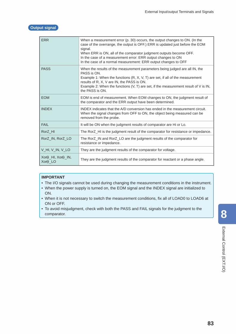
83
External Input/output Terminals and Signals
Output signal
ERR When a measurement error (p. 30) occurs, the output changes to ON. (In the case of the overrange, the output is OFF.) ERR is updated just before the EOM signal. When ERR is ON, all of the comparator judgment outputs become OFF.In the case of a measurement error: ERR output changes to ONIn the case of a normal measurement: ERR output changes to OFF
PASS When the results of the measurement parameters being judged are all IN, the PASS is ON. Example 1: When the functions (R, X, V, T) are set, if all of the measurement results of R, X, V are IN, the PASS is ON. Example 2: When the functions (V, T) are set, if the measurement result of V is IN, the PASS is ON.
EOM EOM is end of measurement. When EOM changes to ON, the judgment result of the comparator and the ERR output have been determined.
INDEX INDEX indicates that the A/D conversion has ended in the measurement circuit. When the signal changes from OFF to ON, the object being measured can be removed from the probe.
FAIL It will be ON when the judgment results of comparator are Hi or Lo.
RorZ_HI The RorZ_HI is the judgment result of the comparator for resistance or impedance.
RorZ_IN, RorZ_LO The RorZ_IN and RorZ_LO are the judgment results of the comparator for resistance or impedance.
V_HI, V_IN, V_LO They are the judgment results of the comparator for voltage.
Xor_HI, Xor_IN, Xor_LO They are the judgment results of the comparator for reactant or a phase angle.
IMPORTANT • The I/O signals cannot be used during changing the measurement conditions in the instrument. • When the power supply is turned on, the EOM signal and the INDEX signal are initialized to ON.
• When it is not necessary to switch the measurement conditions, fi x all of LOAD0 to LOAD6 at ON or OFF.
• To avoid misjudgment, check with both the PASS and FAIL signals for the judgment to the comparator. 8
External C
ontrol (EX
T.I/O)
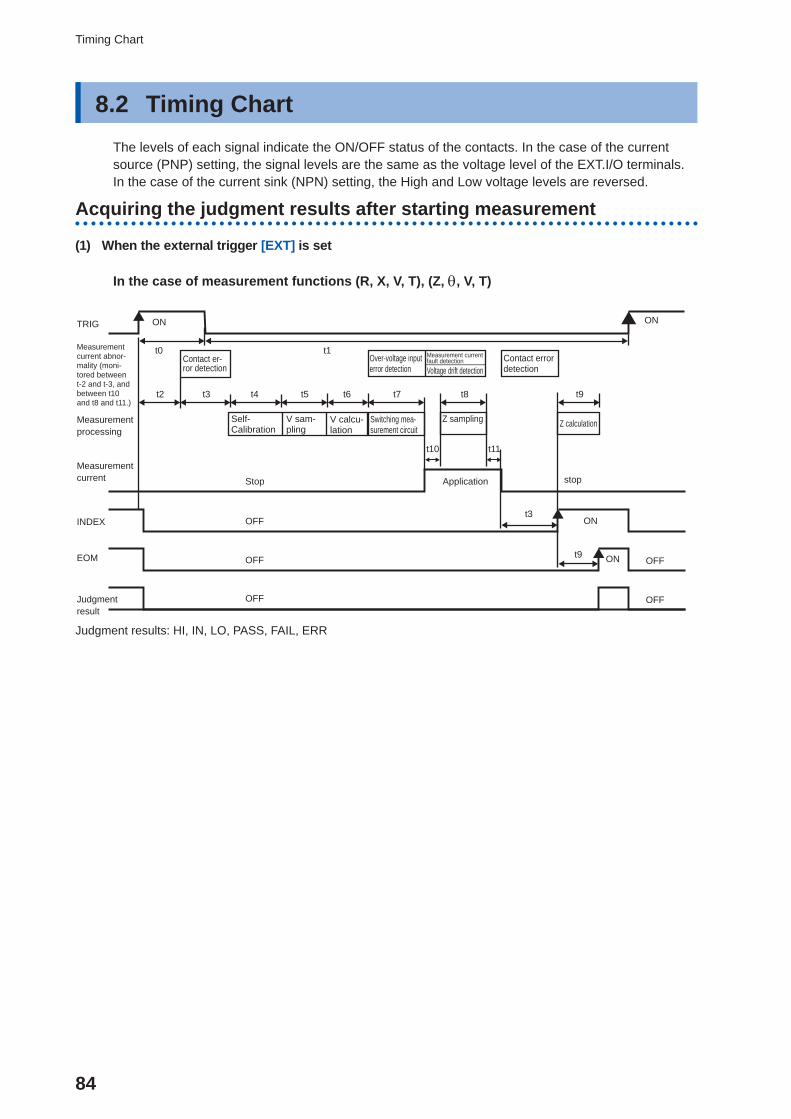
84
Timing Chart
8.2 Timing ChartThe levels of each signal indicate the ON/OFF status of the contacts. In the case of the current source (PNP) setting, the signal levels are the same as the voltage level of the EXT.I/O terminals. In the case of the current sink (NPN) setting, the High and Low voltage levels are reversed.
Acquiring the judgment results after starting measurement
(1) When the external trigger [EXT] is set
In the case of measurement functions (R, X, V, T), (Z, , V, T)
TRIG ON ON
Measurement current abnor-mality (moni-tored between t-2 and t-3, and between t10 and t8 and t11.)
Measurement processing
Measurement current
INDEX
EOM
Judgment result
Contact er-ror detection
Over-voltage input error detection
Measurement current fault detectionVoltage drift detection
Contact error detection
Self-Calibration
V sam-pling
V calcu-lation
Z sampling Z calculation
t2 t3 t4 t5 t6 t7
t10
t8 t9
t3
t9
Stop
OFF
OFF
OFF
ON
ON OFF
OFF
stopApplication
Switching mea-surement circuit
t11
t0 t1
Judgment results: HI, IN, LO, PASS, FAIL, ERR
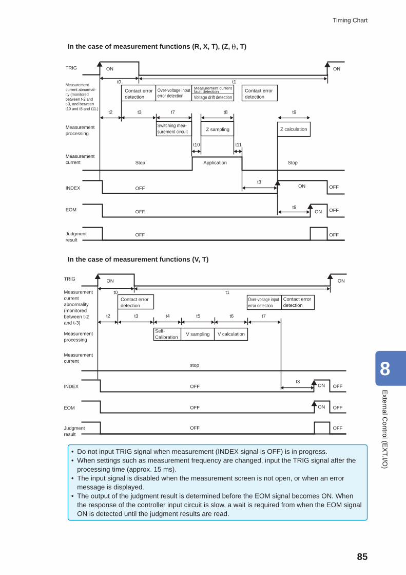
85
Timing Chart
In the case of measurement functions (R, X, T), (Z, , T)
TRIG ON
Measurement current abnormal-ity (monitored between t-2 and t-3, and between t10 and t8 and t11.)
Measurement processing
Measurement current
INDEX
EOM
Judgment result
Contact error detection
Measurement current fault detectionVoltage drift detection
Z sampling Z calculation
t2 t3 t7
t10
t8 t9
Stop
OFF
OFF
OFF
ON
ON OFF
OFF
Over-voltage input error detection
Contact error detection
ON
OFFt3
t9
StopApplication
t11
Switching mea-surement circuit
t0 t1
In the case of measurement functions (V, T)
TRIG ON
Measurement current abnormality (monitored between t-2 and t-3)
Measurement processing
Measurement current
INDEX
EOM
Judgment result
Contact error detection
V sampling V calculation
t2 t3 t7
stop
OFF
OFF
OFF
Over-voltage input error detection
Contact error detection
ON
Self-Calibration
t4 t5 t6
t3ON
ON
OFF
OFF
OFF
t0 t1
• Do not input TRIG signal when measurement (INDEX signal is OFF) is in progress. • When settings such as measurement frequency are changed, input the TRIG signal after the processing time (approx. 15 ms).
• The input signal is disabled when the measurement screen is not open, or when an error message is displayed.
• The output of the judgment result is determined before the EOM signal becomes ON. When the response of the controller input circuit is slow, a wait is required from when the EOM signal ON is detected until the judgment results are read.
8
External C
ontrol (EX
T.I/O)
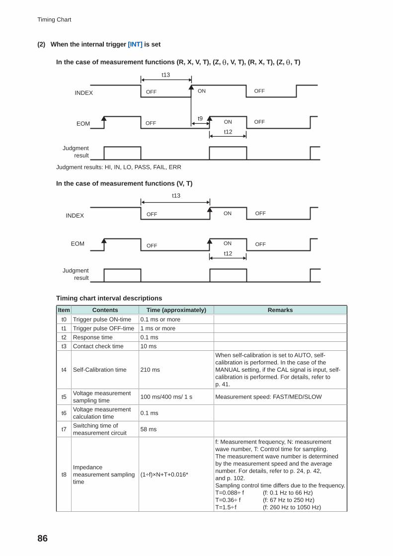
86
Timing Chart
(2) When the internal trigger [INT] is set
In the case of measurement functions (R, X, V, T), (Z, , V, T), (R, X, T), (Z, , T)
INDEX
EOM
Judgment result
t9
OFF
OFF
ON
ON OFF
OFF
t13
t12
Judgment results: HI, IN, LO, PASS, FAIL, ERR
In the case of measurement functions (V, T)
INDEX
EOM
Judgment result
OFF
OFF
ON
ON OFF
OFF
t13
t12
Timing chart interval descriptions
Item Contents Time (approximately) Remarkst0 Trigger pulse ON-time 0.1 ms or moret1 Trigger pulse OFF-time 1 ms or moret2 Response time 0.1 mst3 Contact check time 10 ms
t4 Self-Calibration time 210 ms
When self-calibration is set to AUTO, self-calibration is performed. In the case of the MANUAL setting, if the CAL signal is input, self-calibration is performed. For details, refer to p. 41.
t5 Voltage measurement sampling time 100 ms/400 ms/ 1 s Measurement speed: FAST/MED/SLOW
t6 Voltage measurement calculation time 0.1 ms
t7 Switching time of measurement circuit 58 ms
t8Impedance measurement sampling time
(1÷f)×N+T+0.016*
f: Measurement frequency, N: measurement wave number, T: Control time for sampling.The measurement wave number is determined by the measurement speed and the average number. For details, refer to p. 24, p. 42, and p. 102.Sampling control time differs due to the frequency.T=0.088÷ f (f: 0.1 Hz to 66 Hz)T=0.36÷ f (f: 67 Hz to 250 Hz)T=1.5÷ f (f: 260 Hz to 1050 Hz)
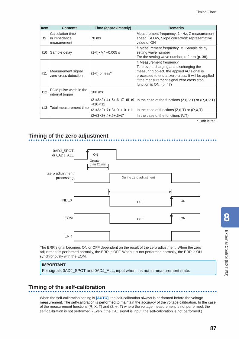
87
Timing Chart
Item Contents Time (approximately) Remarks
t9Calculation time in impedance measurement
70 msMeasurement frequency: 1 kHz, Z measurement speed: SLOW, Slope correction: representative value of ON
t10 Sample delay (1÷f)×M* +0.005 sf: Measurement frequency, M: Sample delay setting wave numberFor the setting wave number, refer to (p. 38).
t11 Measurement signal zero-cross detection (1÷f) or less*
f: Measurement frequencyTo prevent charging and discharging the measuring object, the applied AC signal is processed to end at zero cross. It will be applied if the measurement signal zero cross stop function is ON. (p. 47)
t12 EOM pulse width in the internal trigger 100 ms
t13 Total measurement time
t2+t3×2+t4+t5+t6+t7+t8+t9+t10+t11
In the case of the functions (Z,,V,T) or (R,X,V,T)
t2+t3×2+t7+t8+t9+t10+t11 In the case of functions (Z,,T) or (R,X,T)t2+t3×2+t4+t5+t6+t7 In the case of the functions (V,T)
* Unit is “s”.
Timing of the zero adjustment
EOM OFF
OFF
ON
ON
0ADJ_SPOTor 0ADJ_ALL
Zero adjustment processing
INDEX
ERR
ON
During zero adjustment
Greater than 20 ms
The ERR signal becomes ON or OFF dependent on the result of the zero adjustment. When the zero adjustment is performed normally, the ERR is OFF. When it is not performed normally, the ERR is ON synchronously with the EOM.
IMPORTANTFor signals 0ADJ_SPOT and 0ADJ_ALL, input when it is not in measurement state.
Timing of the self-calibration
When the self-calibration setting is [AUTO], the self-calibration always is performed before the voltage measurement. The self-calibration is performed to maintain the accuracy of the voltage calibration. In the case of the measurement functions (R, X, T) and (Z, , T) where the voltage measurement is not performed, the self-calibration is not performed. (Even if the CAL signal is input, the self-calibration is not performed.)
8
External C
ontrol (EX
T.I/O)
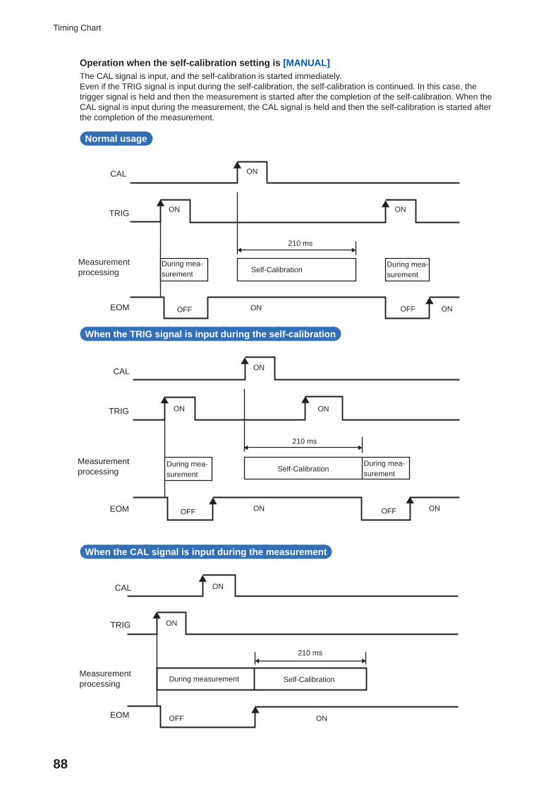
88
Timing Chart
Operation when the self-calibration setting is [MANUAL]The CAL signal is input, and the self-calibration is started immediately.Even if the TRIG signal is input during the self-calibration, the self-calibration is continued. In this case, the trigger signal is held and then the measurement is started after the completion of the self-calibration. When the CAL signal is input during the measurement, the CAL signal is held and then the self-calibration is started after the completion of the measurement.
Normal usage
OFFOFF
ON
ON ON
CAL
TRIG
Measurement processing
EOM ON ON
Self-CalibrationDuring mea-surement
During mea-surement
210 ms
When the TRIG signal is input during the self-calibration
EOM OFF
ON
ON
OFF
CAL
TRIG
Measurement processing
ON ON
ON
Self-CalibrationDuring mea-surement
During mea-surement
210 ms
When the CAL signal is input during the measurement
EOM
ON
OFF
CAL
TRIG
Measurement processing
ON
Self-CalibrationDuring measurement
210 ms
ON
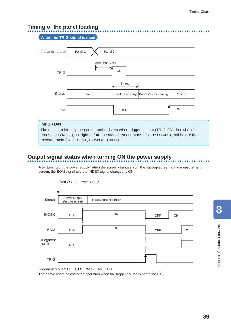
89
Timing Chart
Timing of the panel loading
When the TRIG signal is used
EOM
ON
OFF
TRIG
ON
LOAD0 to LOAD5 Panel 1 Panel 2
Status Panel 1 Load processing Panel 2 is measuring Panel 2
More than 1 ms
84 ms
IMPORTANTThe timing to identify the panel number is not when trigger is input (TRIG:ON), but when it reads the LOAD signal right before the measurement starts. Fix the LOAD signal before the measurement (INDEX:OFF, EOM:OFF) starts.
Output signal status when turning ON the power supply
After turning on the power supply, when the screen changes from the start-up screen to the measurement screen, the EOM signal and the INDEX signal changes to ON.
ONOFF
Status
INDEX
EOM
Judgment result
TRIG
Power supply starting screen Measurement screen
OFF
OFF
ON
OFF
OFF
ON
ON
Turn On the power supply
Judgment results: HI, IN, LO, PASS, FAIL, ERRThe above chart indicates the operation when the trigger source is set to the EXT.
8
External C
ontrol (EX
T.I/O)
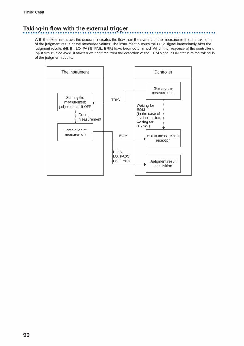
90
Timing Chart
Taking-in fl ow with the external trigger
With the external trigger, the diagram indicates the fl ow from the starting of the measurement to the taking-in of the judgment result or the measured values. The instrument outputs the EOM signal immediately after the judgment results (HI, IN, LO, PASS, FAIL, ERR) have been determined. When the response of the controller’s input circuit is delayed, it takes a waiting time from the detection of the EOM signal’s ON status to the taking-in of the judgment results.
Starting the measurement
judgment result OFF
Completion of measurement
Starting the measurement
End of measurementreception
Judgment resultacquisition
The instrument Controller
TRIGWaiting for EOM(In the case of level detection, waiting for 0.5 ms.)
EOM
HI, IN,LO, PASS, FAIL, ERR
During measurement
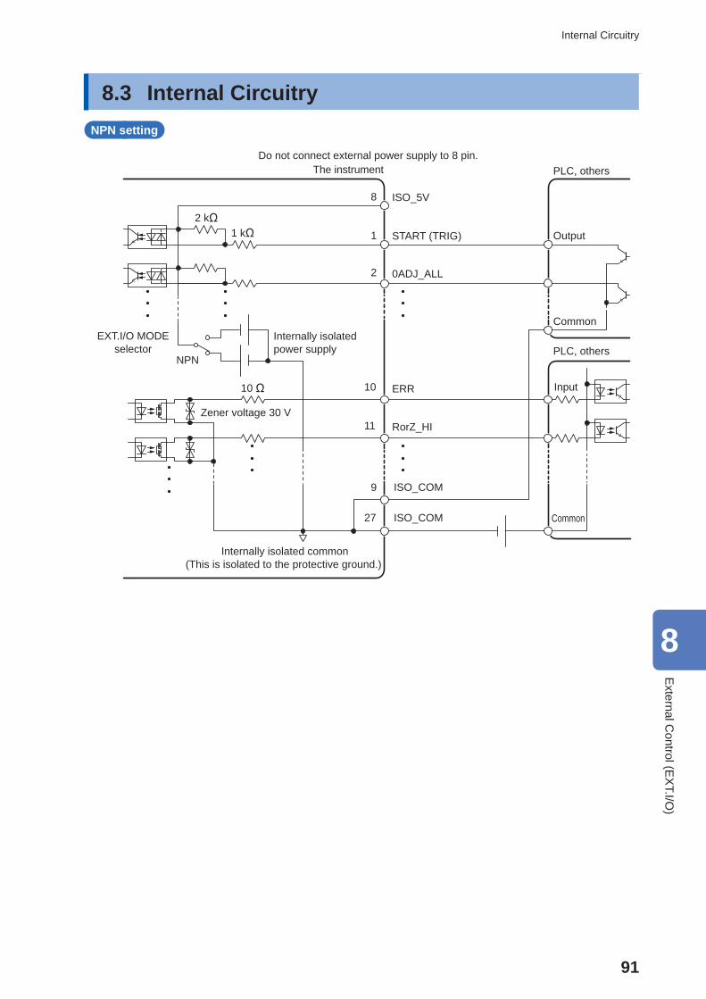
91
Internal Circuitry
8.3 Internal CircuitryNPN setting
PLC, others
Output
Common
Do not connect external power supply to 8 pin.The instrument
8 ISO_5V
1 START (TRIG)
2 0ADJ_ALL
10 ERR
11 RorZ_HI
9 ISO_COM
27 ISO_COM
PLC, others
Input
Common
2 kΩ1 kΩ
10 Ω
Zener voltage 30 V
Internally isolated common(This is isolated to the protective ground.)
NPN
EXT.I/O MODEselector
Internally isolated power supply
8
External C
ontrol (EX
T.I/O)
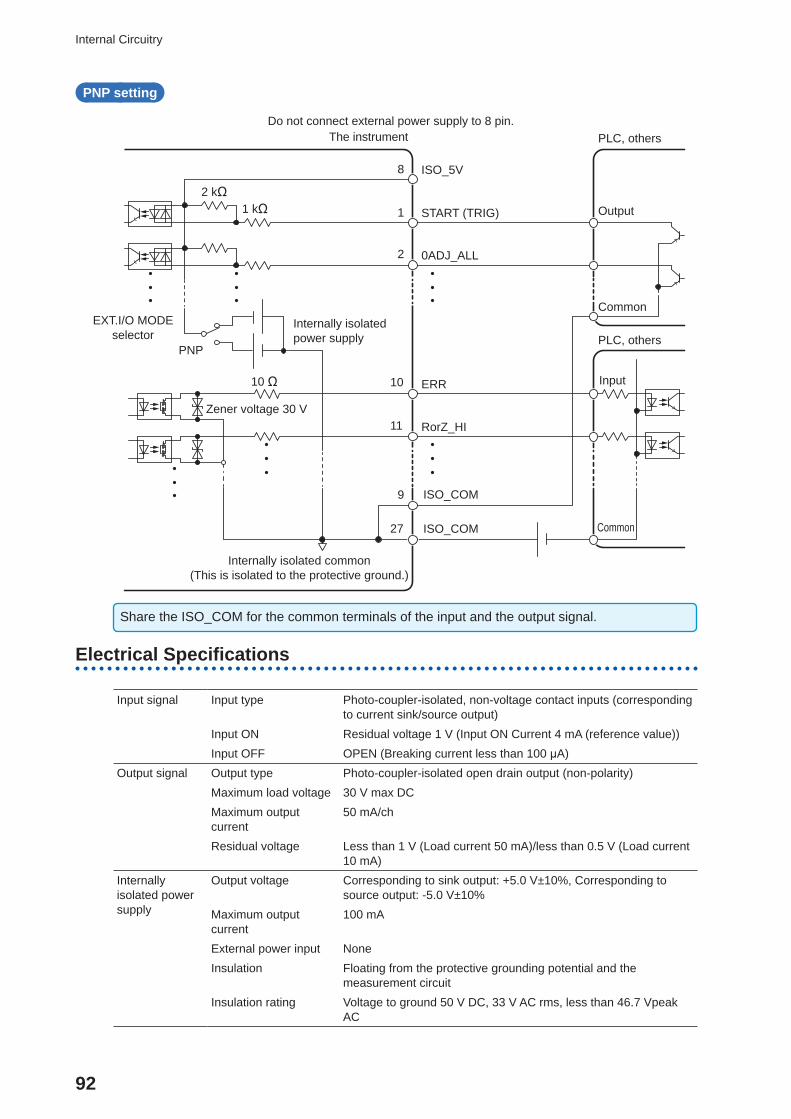
92
Internal Circuitry
PNP setting
PLC, others
Output
Common
Do not connect external power supply to 8 pin.The instrument
8 ISO_5V
1 START (TRIG)
2 0ADJ_ALL
10 ERR
11 RorZ_HI
9 ISO_COM
27 ISO_COM
PLC, others
Input
Common
2 kΩ1 kΩ
10 Ω
Zener voltage 30 V
Internally isolated common(This is isolated to the protective ground.)
PNP
EXT.I/O MODEselector
Internally isolated power supply
Share the ISO_COM for the common terminals of the input and the output signal.
Electrical Specifi cations
Input signal Input type Photo-coupler-isolated, non-voltage contact inputs (corresponding to current sink/source output)
Input ON Residual voltage 1 V (Input ON Current 4 mA (reference value))Input OFF OPEN (Breaking current less than 100 μA)
Output signal Output type Photo-coupler-isolated open drain output (non-polarity)Maximum load voltage 30 V max DCMaximum output current
50 mA/ch
Residual voltage Less than 1 V (Load current 50 mA)/less than 0.5 V (Load current 10 mA)
Internally isolated power supply
Output voltage Corresponding to sink output: +5.0 V±10%, Corresponding to source output: -5.0 V±10%
Maximum output current
100 mA
External power input NoneInsulation Floating from the protective grounding potential and the
measurement circuitInsulation rating Voltage to ground 50 V DC, 33 V AC rms, less than 46.7 Vpeak
AC
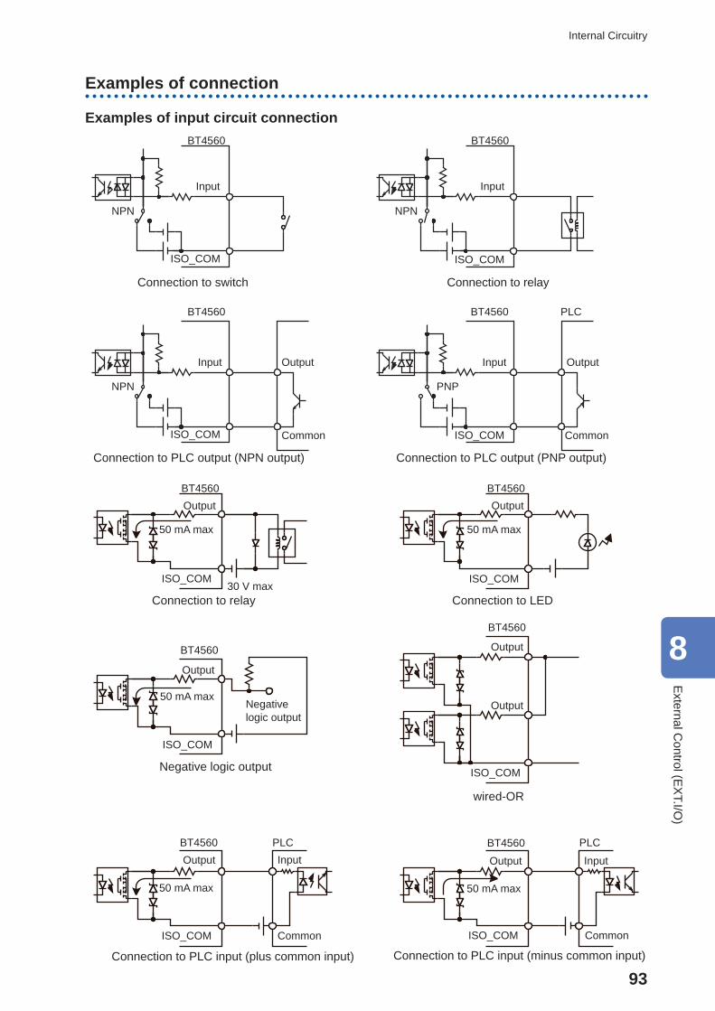
93
Internal Circuitry
Examples of connection
Examples of input circuit connection
Input
ISO_COM
NPN
BT4560 BT4560
Input
ISO_COM
NPN
BT4560 BT4560
Input Input
PLC
OutputOutput
CommonISO_COM ISO_COM Common
NPN PNP
Connection to switch Connection to relay
Connection to PLC output (NPN output) Connection to PLC output (PNP output)
BT4560
BT4560
BT4560
Output OutputBT4560
ISO_COMISO_COM
50 mA max 50 mA max
30 V max
BT4560
Output
50 mA max
ISO_COM
Negative logic output
Output
Output
ISO_COM
BT4560
ISO_COM ISO_COM CommonCommon
PLCInputOutput
50 mA max
InputOutput
50 mA max
PLC
Connection to relay Connection to LED
Negative logic output
wired-OR
Connection to PLC input (plus common input) Connection to PLC input (minus common input)
8
External C
ontrol (EX
T.I/O)
94
Checking the External Control
8.4 Checking the External Control
Testing the inputs/outputs ( EXT.I/O testing functions)
The output signal can be switched ON and OFF manually. In addition, the condition of the input signal can be monitored on the screen.For details, refer to “I/O TEST” (p. 68).
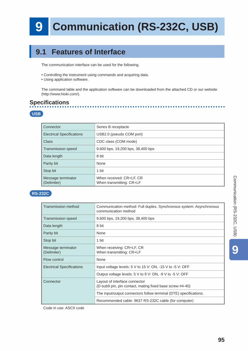
95
9 Communication (RS-232C, USB)
9.1 Features of InterfaceThe communication interface can be used for the following.
• Controlling the instrument using commands and acquiring data. • Using application software.
The command table and the application software can be downloaded from the attached CD or our website (http://www.hioki.com/).
Specifi cations
USB
Connector Series B receptacle
Electrical Specifi cations USB2.0 (pseudo COM port)
Class CDC class (COM mode)
Transmission speed 9,600 bps, 19,200 bps, 38,400 bps
Data length 8 bit
Parity bit None
Stop bit 1 bit
Message terminator(Delimiter)
When received: CR+LF, CRWhen transmitting: CR+LF
RS-232C
Transmission method Communication method: Full duplex, Synchronous system: Asynchronous communication method
Transmission speed 9,600 bps, 19,200 bps, 38,400 bps
Data length 8 bit
Parity bit None
Stop bit 1 bit
Message terminator(Delimiter)
When receiving: CR+LF, CRWhen transmitting: CR+LF
Flow control None
Electrical Specifi cations Input voltage levels: 5 V to 15 V: ON, -15 V to -5 V: OFF
Output voltage levels: 5 V to 9 V: ON, -9 V to -5 V: OFF
Connector Layout of interface connector(D-sub9 pin, pin contact, mating fi xed base screw #4-40)
The input/output connectors follow terminal (DTE) specifi cations.
Recommended cable: 9637 RS-232C cable (for computer)
Code in use: ASCII code
9
Com
munication (R
S-232C
, US
B)
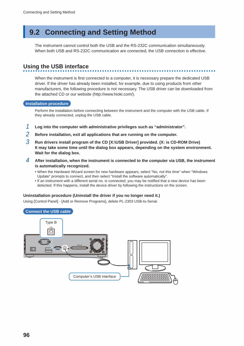
96
Connecting and Setting Method
9.2 Connecting and Setting MethodThe instrument cannot control both the USB and the RS-232C communication simultaneously.When both USB and RS-232C communication are connected, the USB connection is effective.
Using the USB interface
When the instrument is fi rst connected to a computer, it is necessary prepare the dedicated USB driver. If the driver has already been installed, for example, due to using products from other manufacturers, the following procedure is not necessary. The USB driver can be downloaded from the attached CD or our website (http://www.hioki.com/).
Installation procedurePerform the installation before connecting between the instrument and the computer with the USB cable. If they already connected, unplug the USB cable.
1 Log into the computer with administrative privileges such as “administrator”.
2 Before installation, exit all applications that are running on the computer.
3 Run drivers install program of the CD [X:\USB Driver] provided. (X: is CD-ROM Drive)It may take some time until the dialog box appears, depending on the system environment. Wait for the dialog box.
4 After installation, when the instrument is connected to the computer via USB, the instrument is automatically recognized. • When the Hardware Wizard screen for new hardware appears, select “No, not this time” when “Windows Update” prompts to connect, and then select “Install the software automatically”.
• If an instrument with a different serial no. is connected, you may be notifi ed that a new device has been detected. If this happens, install the device driver by following the instructions on the screen.
Uninstallation procedure (Uninstall the driver if you no longer need it.)Using [Control Panel] - [Add or Remove Programs], delete PL-2303 USB-to-Serial.
Connect the USB cable
Computer’s USB interface
Type B
97
Connecting and Setting Method
IMPORTANTThe instrument’s USB port is a pseudo COM port. In the case of the communication, it is necessary to set the speed as well as the RS-232C. In the COM port setting, the COM port number that is allocated to the USB port varies with the computer in use.Check the COM port number that is allocated by the following method.
1. Open the device manager. • In the case of Windows Vista[Start] - [Control Panel] - [Hardware and Sound] - [Device Manager]
• In the case of Windows 7[Start] - [Control Panel] - [System and Security] - [Device Manager]
• In the case of Windows 8[Desktop] - [Right Click on Start] - [Device Manager]
2. The “X” of Prolifi c USB-to-Serial Comm Port (COMX) under “Port (COM and LPL)” is the COM port number.
9
Com
munication (R
S-232C
, US
B)
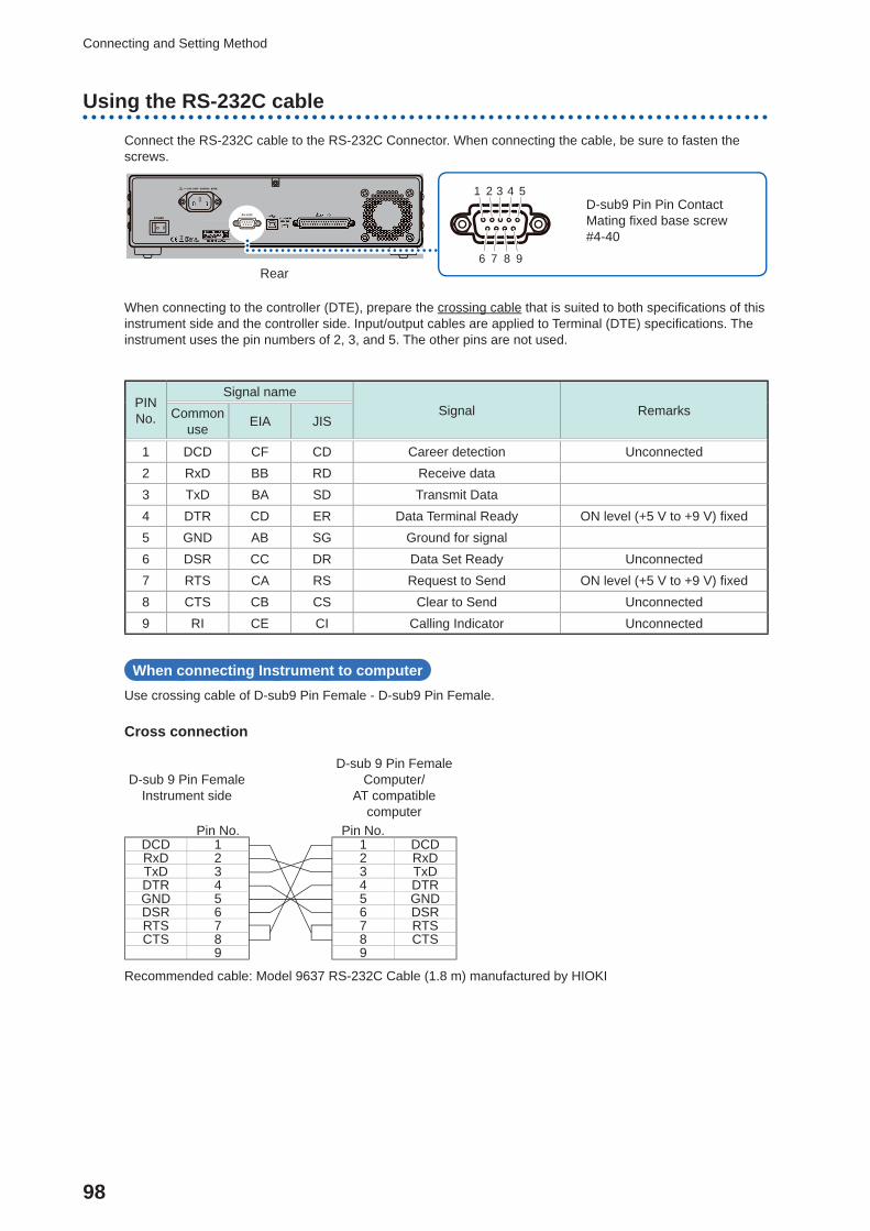
98
Connecting and Setting Method
Using the RS-232C cable
Connect the RS-232C cable to the RS-232C Connector. When connecting the cable, be sure to fasten the screws.
D-sub9 Pin Pin ContactMating fi xed base screw #4-40
1 2 3 4 5
6 7 8 9Rear
When connecting to the controller (DTE), prepare the crossing cable that is suited to both specifi cations of this instrument side and the controller side. Input/output cables are applied to Terminal (DTE) specifi cations. The instrument uses the pin numbers of 2, 3, and 5. The other pins are not used.
PIN No.
Signal nameSignal RemarksCommon
use EIA JIS
1 DCD CF CD Career detection Unconnected2 RxD BB RD Receive data3 TxD BA SD Transmit Data4 DTR CD ER Data Terminal Ready ON level (+5 V to +9 V) fi xed5 GND AB SG Ground for signal6 DSR CC DR Data Set Ready Unconnected7 RTS CA RS Request to Send ON level (+5 V to +9 V) fi xed8 CTS CB CS Clear to Send Unconnected9 RI CE CI Calling Indicator Unconnected
When connecting Instrument to computerUse crossing cable of D-sub9 Pin Female - D-sub9 Pin Female.
Cross connection
D-sub 9 Pin FemaleInstrument side
D-sub 9 Pin FemaleComputer/
AT compatible computer
Pin No. Pin No.DCD 1 1 DCDRxD 2 2 RxDTxD 3 3 TxDDTR 4 4 DTRGND 5 5 GNDDSR 6 6 DSRRTS 7 7 RTSCTS 8 8 CTS
9 9
Recommended cable: Model 9637 RS-232C Cable (1.8 m) manufactured by HIOKI
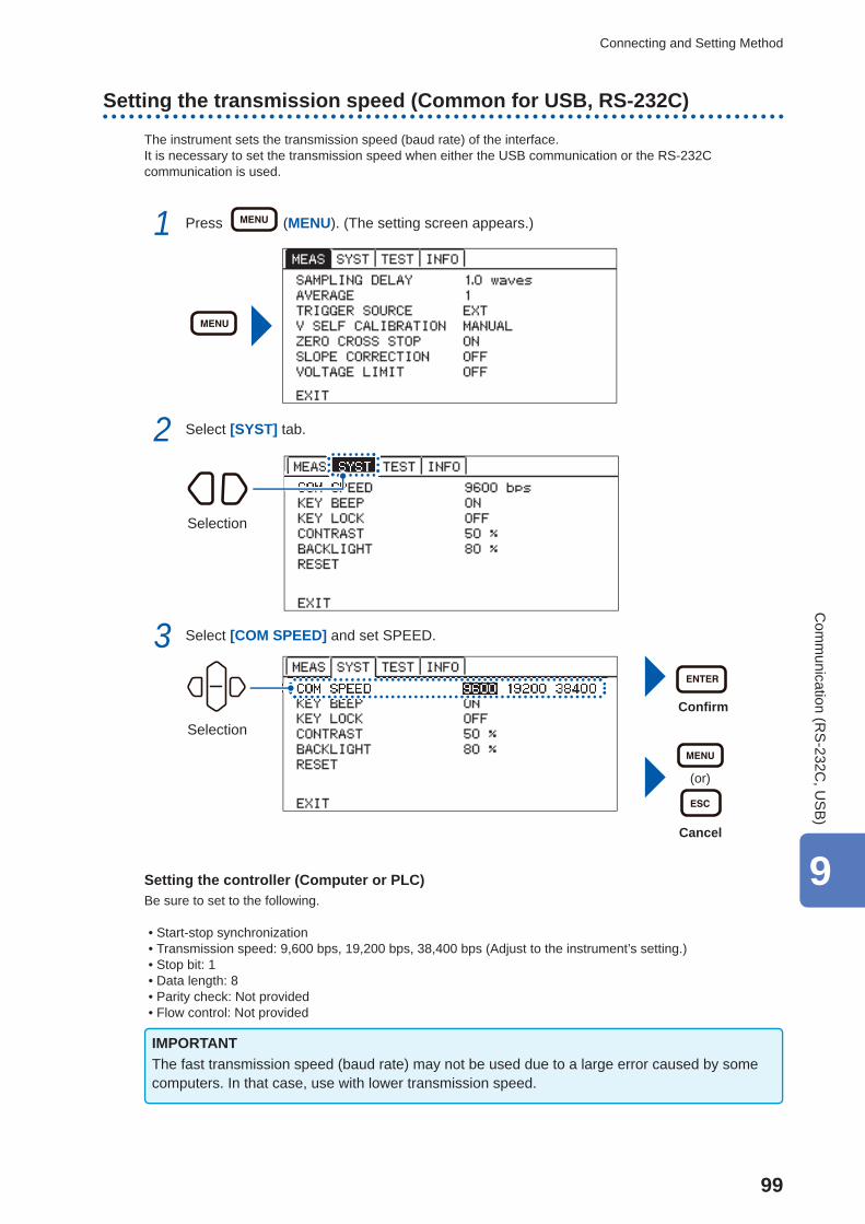
99
Connecting and Setting Method
Setting the transmission speed (Common for USB, RS-232C)
The instrument sets the transmission speed (baud rate) of the interface.It is necessary to set the transmission speed when either the USB communication or the RS-232C communication is used.
1 Press (MENU). (The setting screen appears.)
2 Select [SYST] tab.
Selection
3 Select [COM SPEED] and set SPEED.
Confi rm
(or)
Cancel
Selection
Setting the controller (Computer or PLC)Be sure to set to the following.
• Start-stop synchronization • Transmission speed: 9,600 bps, 19,200 bps, 38,400 bps (Adjust to the instrument’s setting.) • Stop bit: 1 • Data length: 8 • Parity check: Not provided • Flow control: Not provided
IMPORTANTThe fast transmission speed (baud rate) may not be used due to a large error caused by some computers. In that case, use with lower transmission speed.
9
Com
munication (R
S-232C
, US
B)
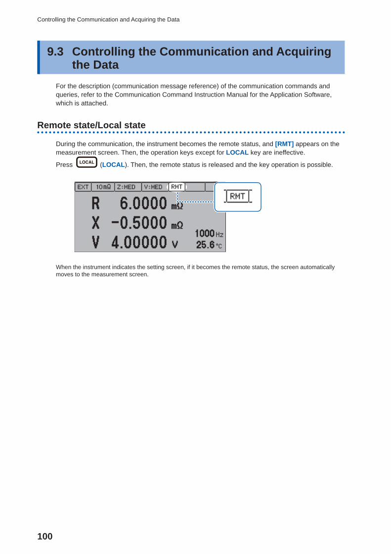
100
Controlling the Communication and Acquiring the Data
9.3 Controlling the Communication and Acquiring the Data
For the description (communication message reference) of the communication commands and queries, refer to the Communication Command Instruction Manual for the Application Software, which is attached.
Remote state/Local state
During the communication, the instrument becomes the remote status, and [RMT] appears on the measurement screen. Then, the operation keys except for LOCAL key are ineffective.
Press (LOCAL). Then, the remote status is released and the key operation is possible.
When the instrument indicates the setting screen, if it becomes the remote status, the screen automatically moves to the measurement screen.
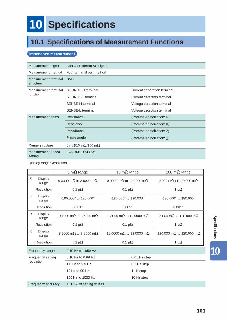
101
10 Specifi cations10.1 Specifi cations of Measurement Functions
Impedance measurement
Measurement signal Constant current AC signal
Measurement method Four-terminal pair method
Measurement terminal structure
BNC
Measurement terminal function
SOURCE-H terminal Current generation terminal
SOURCE-L terminal Current detection terminal
SENSE-H terminal Voltage detection terminal
SENSE-L terminal Voltage detection terminal
Measurement items Resistance (Parameter indication: R)
Reactance (Parameter indication: X)
Impedance (Parameter indication: Z)
Phase angle (Parameter indication: )
Range structure 3 mΩ/10 mΩ/100 mΩ
Measurement speed setting
FAST/MED/SLOW
Display range/Resolution
3 mΩ range 10 mΩ range 100 mΩ range
Z Display range 0.0000 mΩ to 3.6000 mΩ 0.0000 mΩ to 12.0000 mΩ 0.000 mΩ to 120.000 mΩ
Resolution 0.1 μΩ 0.1 μΩ 1 μΩ
Display range -180.000° to 180.000° -180.000° to 180.000° -180.000° to 180.000°
Resolution 0.001° 0.001° 0.001°
R Display range -0.1000 mΩ to 3.6000 mΩ -0.3000 mΩ to 12.0000 mΩ -3.000 mΩ to 120.000 mΩ
Resolution 0.1 μΩ 0.1 μΩ 1 μΩ
X Display range -3.6000 mΩ to 3.6000 mΩ -12.0000 mΩ to 12.0000 mΩ -120.000 mΩ to 120.000 mΩ
Resolution 0.1 μΩ 0.1 μΩ 1 μΩ
Frequency range 0.10 Hz to 1050 Hz
Frequency setting resolution
0.10 Hz to 0.99 Hz 0.01 Hz step
1.0 Hz to 9.9 Hz 0.1 Hz step
10 Hz to 99 Hz 1 Hz step
100 Hz to 1050 Hz 10 Hz step
Frequency accuracy ±0.01% of setting or less
10
Specifi cations
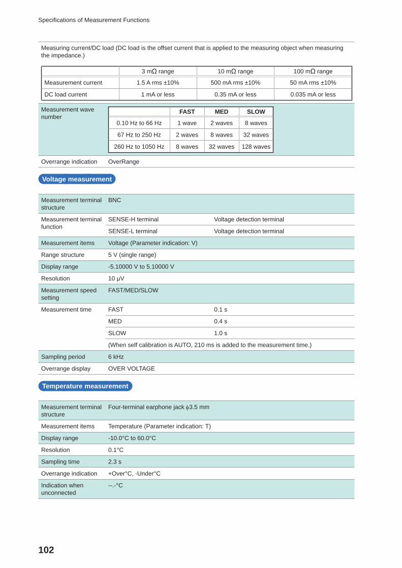
102
Specifi cations of Measurement Functions
Measuring current/DC load (DC load is the offset current that is applied to the measuring object when measuring the impedance.)
3 mΩ range 10 mΩ range 100 mΩ range
Measurement current 1.5 A rms ±10% 500 mA rms ±10% 50 mA rms ±10%
DC load current 1 mA or less 0.35 mA or less 0.035 mA or less
Measurement wave number
FAST MED SLOW
0.10 Hz to 66 Hz 1 wave 2 waves 8 waves
67 Hz to 250 Hz 2 waves 8 waves 32 waves
260 Hz to 1050 Hz 8 waves 32 waves 128 waves
Overrange indication OverRange
Voltage measurement
Measurement terminal structure
BNC
Measurement terminal function
SENSE-H terminal Voltage detection terminal
SENSE-L terminal Voltage detection terminal
Measurement items Voltage (Parameter indication: V)
Range structure 5 V (single range)
Display range -5.10000 V to 5.10000 V
Resolution 10 μV
Measurement speed setting
FAST/MED/SLOW
Measurement time FAST 0.1 s
MED 0.4 s
SLOW 1.0 s
(When self calibration is AUTO, 210 ms is added to the measurement time.)
Sampling period 6 kHz
Overrange display OVER VOLTAGE
Temperature measurement
Measurement terminal structure
Four-terminal earphone jack 3.5 mm
Measurement items Temperature (Parameter indication: T)
Display range -10.0°C to 60.0°C
Resolution 0.1°C
Sampling time 2.3 s
Overrange indication +Over°C, -Under°C
Indication when unconnected
--.-°C
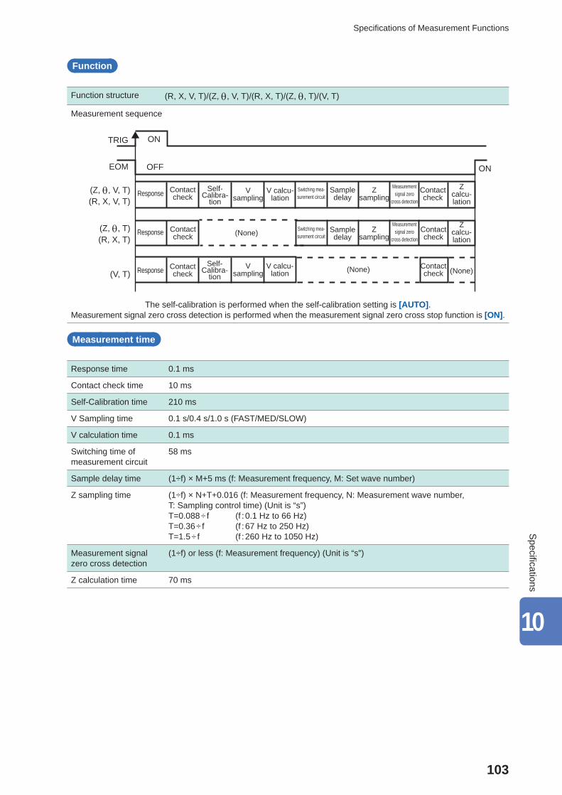
103
Specifi cations of Measurement Functions
Function
Function structure (R, X, V, T)/(Z, , V, T)/(R, X, T)/(Z, , T)/(V, T)
Measurement sequence
TRIG
EOM
(Z, , V, T)(R, X, V, T)
(Z, , T)(R, X, T)
(V, T)
ON
ON
OFF
Contact check
Self-Calibra-
tion
Self-Calibra-
tion
V sampling
V sampling
V calcu-lation
V calcu-lation
Switching mea-surement circuit
Sample delay
Sample delay
Z sampling
Z sampling
Contact check
Contact check
(None)
(None)
Switching mea-surement circuit
Measurement signal zero
cross detection
Measurement signal zero
cross detection
Contact check
Contact check
Contact check
Z calcu-lation
Z calcu-lation
(None)
Response
Response
Response
The self-calibration is performed when the self-calibration setting is [AUTO].Measurement signal zero cross detection is performed when the measurement signal zero cross stop function is [ON].
Measurement time
Response time 0.1 ms
Contact check time 10 ms
Self-Calibration time 210 ms
V Sampling time 0.1 s/0.4 s/1.0 s (FAST/MED/SLOW)
V calculation time 0.1 ms
Switching time of measurement circuit
58 ms
Sample delay time (1÷f) × M+5 ms (f: Measurement frequency, M: Set wave number)
Z sampling time (1÷f) × N+T+0.016 (f: Measurement frequency, N: Measurement wave number, T: Sampling control time) (Unit is “s”)T=0.088 ÷ f (f : 0.1 Hz to 66 Hz)T=0.36 ÷ f (f : 67 Hz to 250 Hz)T=1.5 ÷ f (f : 260 Hz to 1050 Hz)
Measurement signal zero cross detection
(1÷f) or less (f: Measurement frequency) (Unit is “s”)
Z calculation time 70 ms
10
Specifi cations
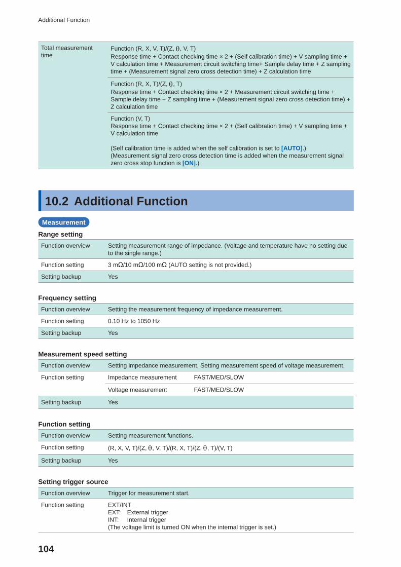
104
Additional Function
Total measurement time
Function (R, X, V, T)/(Z, , V, T)Response time + Contact checking time × 2 + (Self calibration time) + V sampling time + V calculation time + Measurement circuit switching time+ Sample delay time + Z sampling time + (Measurement signal zero cross detection time) + Z calculation time
Function (R, X, T)/(Z, , T)Response time + Contact checking time × 2 + Measurement circuit switching time + Sample delay time + Z sampling time + (Measurement signal zero cross detection time) + Z calculation time
Function (V, T)Response time + Contact checking time × 2 + (Self calibration time) + V sampling time + V calculation time
(Self calibration time is added when the self calibration is set to [AUTO].)(Measurement signal zero cross detection time is added when the measurement signal zero cross stop function is [ON].)
10.2 Additional FunctionMeasurement
Range settingFunction overview Setting measurement range of impedance. (Voltage and temperature have no setting due
to the single range.)
Function setting 3 mΩ/10 mΩ/100 mΩ (AUTO setting is not provided.)
Setting backup Yes
Frequency settingFunction overview Setting the measurement frequency of impedance measurement.
Function setting 0.10 Hz to 1050 Hz
Setting backup Yes
Measurement speed settingFunction overview Setting impedance measurement, Setting measurement speed of voltage measurement.
Function setting Impedance measurement FAST/MED/SLOW
Voltage measurement FAST/MED/SLOW
Setting backup Yes
Function settingFunction overview Setting measurement functions.
Function setting (R, X, V, T)/(Z, , V, T)/(R, X, T)/(Z, , T)/(V, T)
Setting backup Yes
Setting trigger sourceFunction overview Trigger for measurement start.
Function setting EXT/INTEXT: External triggerINT: Internal trigger(The voltage limit is turned ON when the internal trigger is set.)
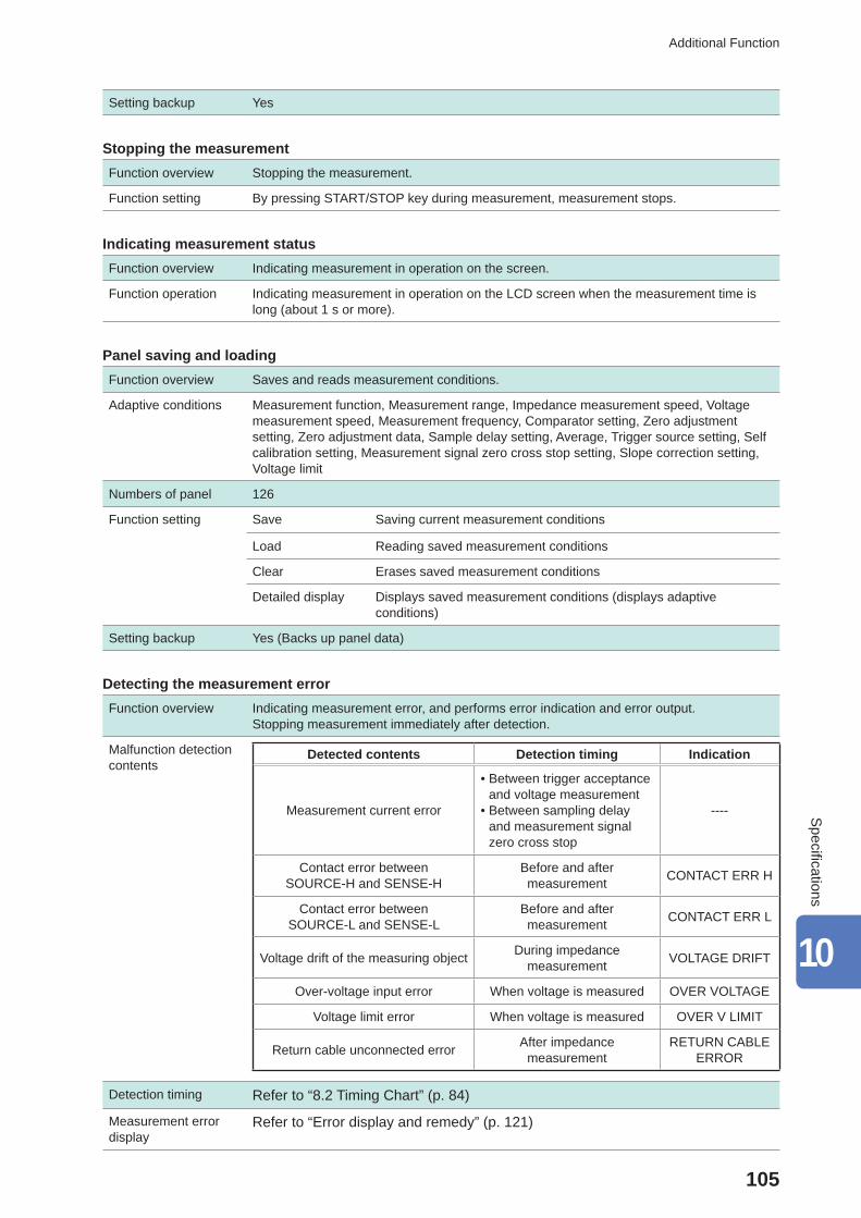
105
Additional Function
Setting backup Yes
Stopping the measurementFunction overview Stopping the measurement.
Function setting By pressing START/STOP key during measurement, measurement stops.
Indicating measurement statusFunction overview Indicating measurement in operation on the screen.
Function operation Indicating measurement in operation on the LCD screen when the measurement time is long (about 1 s or more).
Panel saving and loadingFunction overview Saves and reads measurement conditions.
Adaptive conditions Measurement function, Measurement range, Impedance measurement speed, Voltage measurement speed, Measurement frequency, Comparator setting, Zero adjustment setting, Zero adjustment data, Sample delay setting, Average, Trigger source setting, Self calibration setting, Measurement signal zero cross stop setting, Slope correction setting, Voltage limit
Numbers of panel 126
Function setting Save Saving current measurement conditions
Load Reading saved measurement conditions
Clear Erases saved measurement conditions
Detailed display Displays saved measurement conditions (displays adaptive conditions)
Setting backup Yes (Backs up panel data)
Detecting the measurement errorFunction overview Indicating measurement error, and performs error indication and error output.
Stopping measurement immediately after detection.
Malfunction detection contents
Detected contents Detection timing Indication
Measurement current error
• Between trigger acceptance and voltage measurement
• Between sampling delay and measurement signal zero cross stop
----
Contact error between SOURCE-H and SENSE-H
Before and after measurement CONTACT ERR H
Contact error between SOURCE-L and SENSE-L
Before and after measurement CONTACT ERR L
Voltage drift of the measuring object During impedance measurement VOLTAGE DRIFT
Over-voltage input error When voltage is measured OVER VOLTAGE
Voltage limit error When voltage is measured OVER V LIMIT
Return cable unconnected error After impedance measurement
RETURN CABLE ERROR
Detection timing Refer to “8.2 Timing Chart” (p. 84)
Measurement error display
Refer to “Error display and remedy” (p. 121)
10
Specifi cations
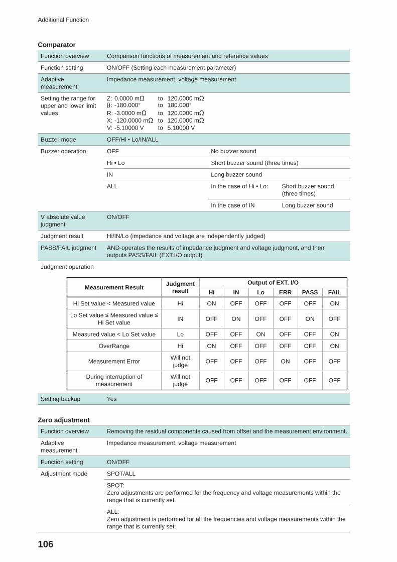
106
Additional Function
ComparatorFunction overview Comparison functions of measurement and reference values
Function setting ON/OFF (Setting each measurement parameter)
Adaptive measurement
Impedance measurement, voltage measurement
Setting the range for upper and lower limit values
Z: 0.0000 mΩ to 120.0000 mΩ: -180.000° to 180.000°R: -3.0000 mΩ to 120.0000 mΩX: -120.0000 mΩ to 120.0000 mΩV: -5.10000 V to 5.10000 V
Buzzer mode OFF/Hi • Lo/IN/ALL
Buzzer operation OFF No buzzer sound
Hi • Lo Short buzzer sound (three times)
IN Long buzzer sound
ALL In the case of Hi • Lo: Short buzzer sound (three times)
In the case of IN Long buzzer sound
V absolute value judgment
ON/OFF
Judgment result Hi/IN/Lo (impedance and voltage are independently judged)
PASS/FAIL judgment AND-operates the results of impedance judgment and voltage judgment, and thenoutputs PASS/FAIL (EXT.I/O output)
Judgment operation
Measurement Result Judgment result
Output of EXT. I/OHi IN Lo ERR PASS FAIL
Hi Set value < Measured value Hi ON OFF OFF OFF OFF ON
Lo Set value ≤ Measured value ≤ Hi Set value IN OFF ON OFF OFF ON OFF
Measured value < Lo Set value Lo OFF OFF ON OFF OFF ON
OverRange Hi ON OFF OFF OFF OFF ON
Measurement Error Will not judge OFF OFF OFF ON OFF OFF
During interruption of measurement
Will not judge OFF OFF OFF OFF OFF OFF
Setting backup Yes
Zero adjustmentFunction overview Removing the residual components caused from offset and the measurement environment.
Adaptive measurement
Impedance measurement, voltage measurement
Function setting ON/OFF
Adjustment mode SPOT/ALL
SPOT:Zero adjustments are performed for the frequency and voltage measurements within the range that is currently set.
ALL:Zero adjustment is performed for all the frequencies and voltage measurements within the range that is currently set.
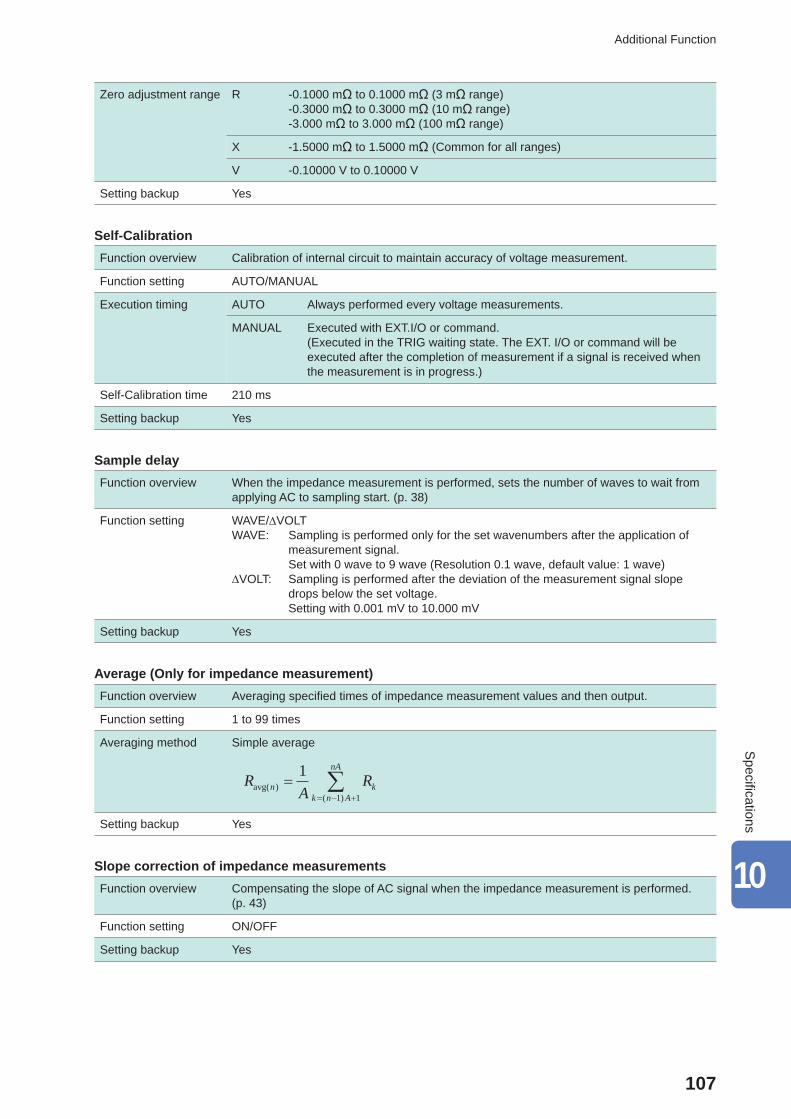
107
Additional Function
Zero adjustment range R -0.1000 mΩ to 0.1000 mΩ (3 mΩ range)-0.3000 mΩ to 0.3000 mΩ (10 mΩ range)-3.000 mΩ to 3.000 mΩ (100 mΩ range)
X -1.5000 mΩ to 1.5000 mΩ (Common for all ranges)
V -0.10000 V to 0.10000 V
Setting backup Yes
Self-CalibrationFunction overview Calibration of internal circuit to maintain accuracy of voltage measurement.
Function setting AUTO/MANUAL
Execution timing AUTO Always performed every voltage measurements.
MANUAL Executed with EXT.I/O or command.(Executed in the TRIG waiting state. The EXT. I/O or command will be executed after the completion of measurement if a signal is received when the measurement is in progress.)
Self-Calibration time 210 ms
Setting backup Yes
Sample delayFunction overview When the impedance measurement is performed, sets the number of waves to wait from
applying AC to sampling start. (p. 38)
Function setting WAVE/VOLTWAVE: Sampling is performed only for the set wavenumbers after the application of
measurement signal. Set with 0 wave to 9 wave (Resolution 0.1 wave, default value: 1 wave)∆VOLT: Sampling is performed after the deviation of the measurement signal slope
drops below the set voltage. Setting with 0.001 mV to 10.000 mV
Setting backup Yes
Average (Only for impedance measurement)Function overview Averaging specifi ed times of impedance measurement values and then output.
Function setting 1 to 99 times
Averaging method Simple average
RA
Rn kk n A
nA
avg( )( )
11 1
Setting backup Yes
Slope correction of impedance measurementsFunction overview Compensating the slope of AC signal when the impedance measurement is performed.
(p. 43)
Function setting ON/OFF
Setting backup Yes
10
Specifi cations
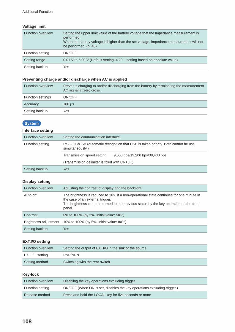
108
Additional Function
Voltage limitFunction overview Setting the upper limit value of the battery voltage that the impedance measurement is
performed.When the battery voltage is higher than the set voltage, impedance measurement will not be performed. (p. 45)
Function setting ON/OFF
Setting range 0.01 V to 5.00 V (Default setting: 4.20 setting based on absolute value)
Setting backup Yes
Preventing charge and/or discharge when AC is appliedFunction overview Prevents charging to and/or discharging from the battery by terminating the measurement
AC signal at zero cross.
Function settings ON/OFF
Accuracy ±80 μs
Setting backup Yes
System
Interface settingFunction overview Setting the communication interface.
Function setting RS-232C/USB (automatic recognition that USB is taken priority. Both cannot be use simultaneously.)
Transmission speed setting 9,600 bps/19,200 bps/38,400 bps
(Transmission delimiter is fi xed with CR+LF.)
Setting backup Yes
Display settingFunction overview Adjusting the contrast of display and the backlight.
Auto-off The brightness is reduced to 10% if a non-operational state continues for one minute in the case of an external trigger.The brightness can be returned to the previous status by the key operation on the front panel.
Contrast 0% to 100% (by 5%, initial value: 50%)
Brightness adjustment 10% to 100% (by 5%, initial value: 80%)
Setting backup Yes
EXT.I/O settingFunction overview Setting the output of EXTI/O in the sink or the source.
EXT.I/O setting PNP/NPN
Setting method Switching with the rear switch
Key-lockFunction overview Disabling the key operations excluding trigger.
Function setting ON/OFF (When ON is set, disables the key operations excluding trigger.)
Release method Press and hold the LOCAL key for fi ve seconds or more
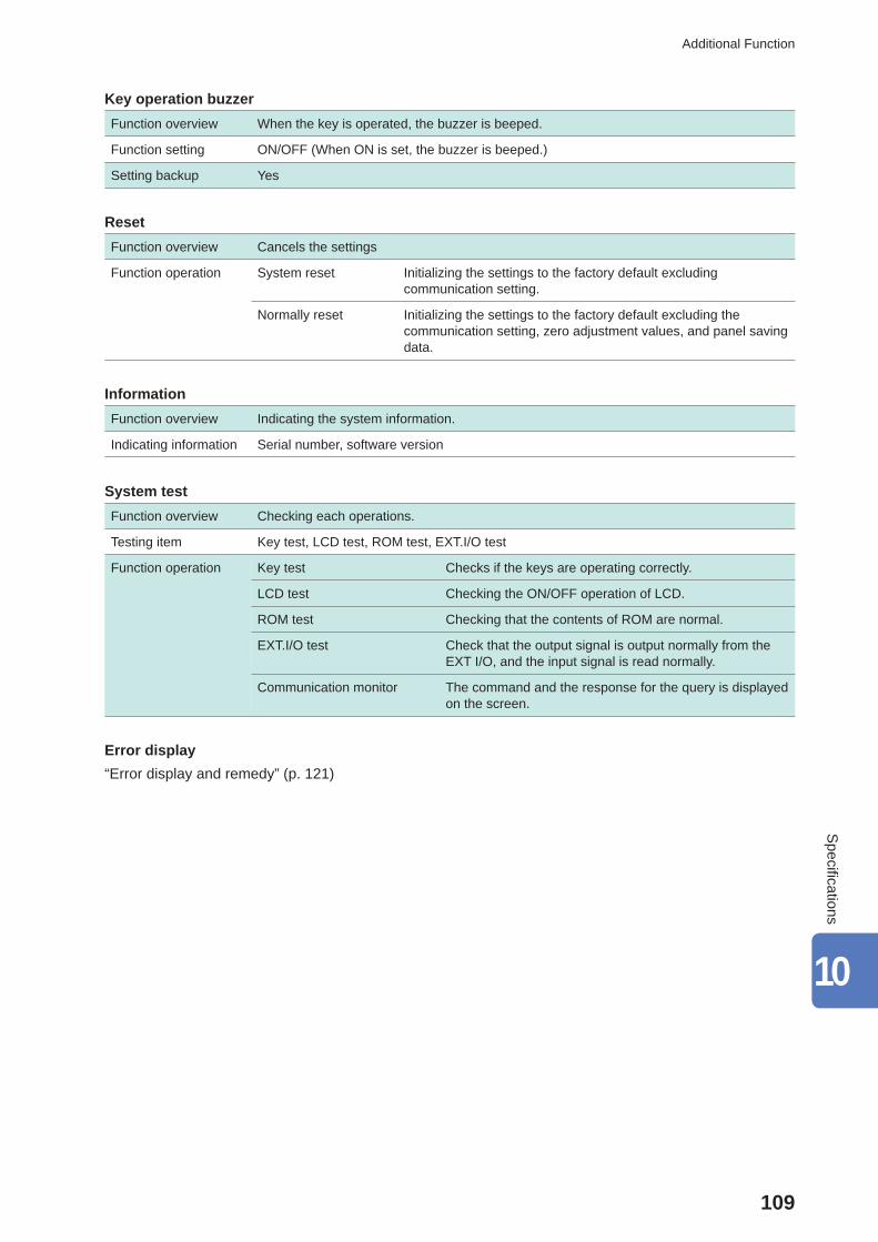
109
Additional Function
Key operation buzzerFunction overview When the key is operated, the buzzer is beeped.
Function setting ON/OFF (When ON is set, the buzzer is beeped.)
Setting backup Yes
ResetFunction overview Cancels the settings
Function operation System reset Initializing the settings to the factory default excluding communication setting.
Normally reset Initializing the settings to the factory default excluding the communication setting, zero adjustment values, and panel saving data.
InformationFunction overview Indicating the system information.
Indicating information Serial number, software version
System testFunction overview Checking each operations.
Testing item Key test, LCD test, ROM test, EXT.I/O test
Function operation Key test Checks if the keys are operating correctly.
LCD test Checking the ON/OFF operation of LCD.
ROM test Checking that the contents of ROM are normal.
EXT.I/O test Check that the output signal is output normally from the EXT I/O, and the input signal is read normally.
Communication monitor The command and the response for the query is displayed on the screen.
Error display“Error display and remedy” (p. 121)
10
Specifi cations
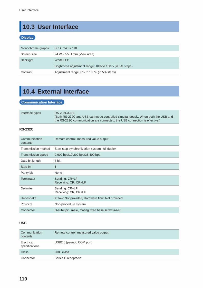
110
User Interface
10.3 User InterfaceDisplay
Monochrome graphic LCD 240 × 110
Screen size 94 W × 55 H mm (View area)
Backlight White LED
Brightness adjustment range: 10% to 100% (in 5% steps)
Contrast Adjustment range: 0% to 100% (in 5% steps)
10.4 External InterfaceCommunication Interface
Interface types RS-232C/USB(Both RS-232C and USB cannot be controlled simultaneously. When both the USB and the RS-232C communication are connected, the USB connection is effective.)
RS-232C
Communication contents
Remote control, measured value output
Transmission method Start-stop synchronization system, full duplex
Transmission speed 9,600 bps/19,200 bps/38,400 bps
Data bit length 8 bit
Stop bit 1
Parity bit None
Terminator Sending: CR+LFReceiving: CR, CR+LF
Delimiter Sending: CR+LFReceiving: CR, CR+LF
Handshake X fl ow: Not provided, Hardware fl ow: Not provided
Protocol Non-procedure system
Connector D-sub9 pin, male, mating fi xed base screw #4-40
USB
Communication contents
Remote control, measured value output
Electrical specifi cations
USB2.0 (pseudo COM port)
Class CDC class
Connector Series B receptacle
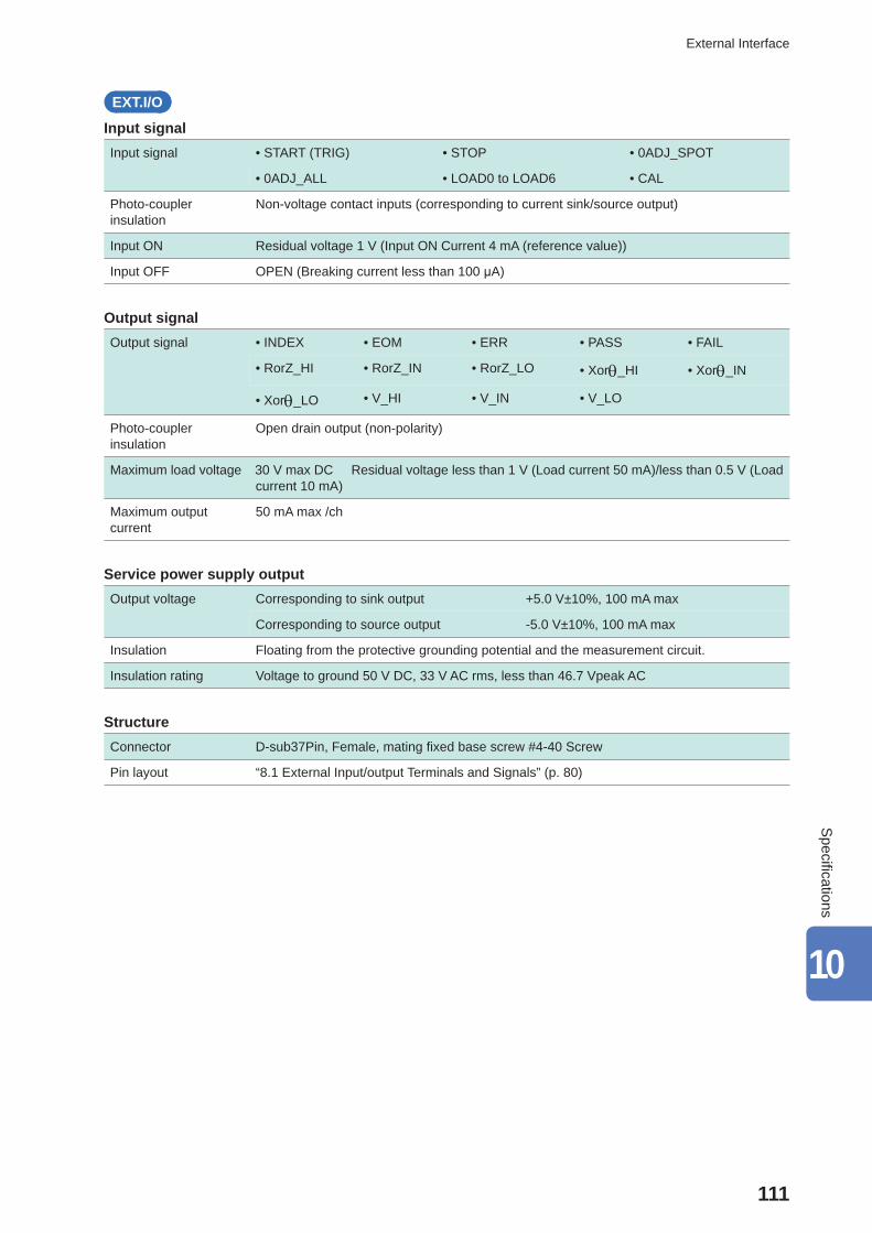
111
External Interface
EXT.I/O
Input signalInput signal • START (TRIG) • STOP • 0ADJ_SPOT
• 0ADJ_ALL • LOAD0 to LOAD6 • CAL
Photo-coupler insulation
Non-voltage contact inputs (corresponding to current sink/source output)
Input ON Residual voltage 1 V (Input ON Current 4 mA (reference value))
Input OFF OPEN (Breaking current less than 100 μA)
Output signalOutput signal • INDEX • EOM • ERR • PASS • FAIL
• RorZ_HI • RorZ_IN • RorZ_LO • Xor_HI • Xor_IN
• Xor_LO • V_HI • V_IN • V_LO
Photo-coupler insulation
Open drain output (non-polarity)
Maximum load voltage 30 V max DC Residual voltage less than 1 V (Load current 50 mA)/less than 0.5 V (Load current 10 mA)
Maximum output current
50 mA max /ch
Service power supply outputOutput voltage Corresponding to sink output +5.0 V±10%, 100 mA max
Corresponding to source output -5.0 V±10%, 100 mA max
Insulation Floating from the protective grounding potential and the measurement circuit.
Insulation rating Voltage to ground 50 V DC, 33 V AC rms, less than 46.7 Vpeak AC
StructureConnector D-sub37Pin, Female, mating fi xed base screw #4-40 Screw
Pin layout “8.1 External Input/output Terminals and Signals” (p. 80)
10
Specifi cations
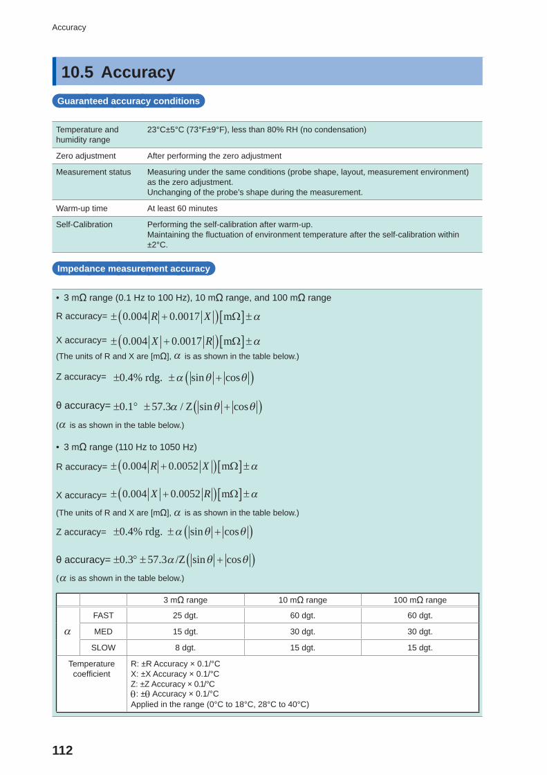
112
Accuracy
10.5 Accuracy Guaranteed accuracy conditions
Temperature and humidity range
23°C±5°C (73°F±9°F), less than 80% RH (no condensation)
Zero adjustment After performing the zero adjustment
Measurement status Measuring under the same conditions (probe shape, layout, measurement environment) as the zero adjustment.Unchanging of the probe’s shape during the measurement.
Warm-up time At least 60 minutes
Self-Calibration Performing the self-calibration after warm-up.Maintaining the fl uctuation of environment temperature after the self-calibration within ±2°C.
Impedance measurement accuracy
• 3 mΩ range (0.1 Hz to 100 Hz), 10 mΩ range, and 100 mΩ range
0 004 0 0017. .R X mR accuracy=
X accuracy= 0 004 0 0017. .X R m(The units of R and X are [mΩ], is as shown in the table below.)
Z accuracy=
θ accuracy=
0 4. sin cos% rdg.
0 1 57 3. . / sin cos Z( is as shown in the table below.)
• 3 mΩ range (110 Hz to 1050 Hz)
R accuracy=
X accuracy=
0 004 0 0052. .R X m
0 004 0 0052. .X R m
(The units of R and X are [mΩ], is as shown in the table below.)
Z accuracy= 0.4% rdg. sin cos
θ accuracy= 0.3 57.3 /Z sin cos( is as shown in the table below.)
3 mΩ range 10 mΩ range 100 mΩ range
FAST 25 dgt. 60 dgt. 60 dgt.
MED 15 dgt. 30 dgt. 30 dgt.
SLOW 8 dgt. 15 dgt. 15 dgt.
Temperature coeffi cient
R: ±R Accuracy × 0.1/°CX: ±X Accuracy × 0.1/°CZ: ±Z Accuracy × 0.1/°C: ± Accuracy × 0.1/°CApplied in the range (0°C to 18°C, 28°C to 40°C)
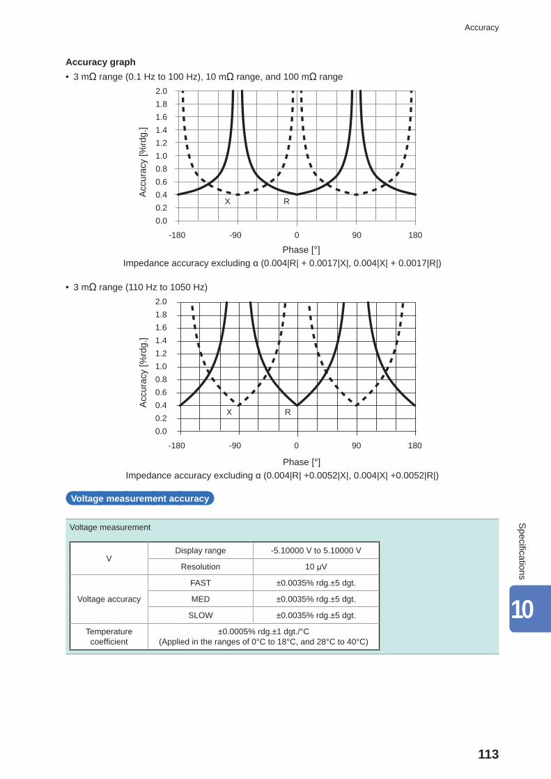
113
Accuracy
Accuracy graph • 3 mΩ range (0.1 Hz to 100 Hz), 10 mΩ range, and 100 mΩ range
2.01.81.61.41.21.00.80.60.40.20.0
-180 -90 0 90 180
X R
Acc
urac
y [%
rdg.
]
Phase [°]Impedance accuracy excluding α (0.004|R| + 0.0017|X|, 0.004|X| + 0.0017|R|)
• 3 mΩ range (110 Hz to 1050 Hz)2.01.81.61.41.21.00.80.60.40.20.0
-180 -90 0 90 180
X R
Acc
urac
y [%
rdg.
]
Phase [°]Impedance accuracy excluding α (0.004|R| +0.0052|X|, 0.004|X| +0.0052|R|)
Voltage measurement accuracy
Voltage measurement
VDisplay range -5.10000 V to 5.10000 V
Resolution 10 μV
Voltage accuracy
FAST ±0.0035% rdg.±5 dgt.
MED ±0.0035% rdg.±5 dgt.
SLOW ±0.0035% rdg.±5 dgt.
Temperature coeffi cient
±0.0005% rdg.±1 dgt./°C (Applied in the ranges of 0°C to 18°C, and 28°C to 40°C)
10
Specifi cations
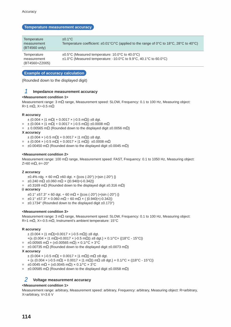
114
Accuracy
Temperature measurement accuracy
Temperature measurement (BT4560 only)
±0.1°CTemperature coeffi cient: ±0.01°C/°C (applied to the range of 0°C to 18°C, 28°C to 40°C)
Temperature measurement(BT4560+Z2005)
±0.5°C (Measured temperature: 10.0°C to 40.0°C)±1.0°C (Measured temperature: -10.0°C to 9.9°C, 40.1°C to 60.0°C)
Example of accuracy calculation
(Rounded down to the displayed digit)
1 Impedance measurement accuracy<Measurement condition 1>Measurement range: 3 mΩ range, Measurement speed: SLOW, Frequency: 0.1 to 100 Hz, Measuring object: R=1 mΩ, X=-0.5 mΩ
R accuracy ± (0.004 × |1 mΩ| + 0.0017 × |-0.5 mΩ|) ±8 dgt.= ± (0.004 × |1 mΩ| + 0.0017 × |-0.5 mΩ|) ±0.0008 mΩ= ± 0.00565 mΩ (Rounded down to the displayed digit ±0.0056 mΩ)X accuracy ± (0.004 × |-0.5 mΩ| + 0.0017 × |1 mΩ|) ±8 dgt.= ± (0.004 × |-0.5 mΩ| + 0.0017 × |1 mΩ|) ±0.0008 mΩ= ±0.00450 mΩ (Rounded down to the displayed digit ±0.0045 mΩ)
<Measurement condition 2>Measurement range: 100 mΩ range, Measurement speed: FAST, Frequency: 0.1 to 1050 Hz, Measuring object: Z=60 mΩ, =-20°
Z accuracy ±0.4% rdg. × 60 mΩ ±60 dgt. × {|cos (-20°) |+|sin (-20°) |}= ±0.240 mΩ ±0.060 mΩ × (|0.940|+|-0.342|) = ±0.3169 mΩ (Rounded down to the displayed digit ±0.316 mΩ) accuracy ±0.1° ±57.3° × 60 dgt. ÷ 60 mΩ × {|cos (-20°) |+|sin (-20°) |}= ±0.1° ±57.3° × 0.060 mΩ ÷ 60 mΩ × ( |0.940|+|-0.342|) = ±0.1734° (Rounded down to the displayed digit ±0.173°)
<Measurement condition 3>Measurement range: 3 mΩ range, Measurement speed: SLOW, Frequency: 0.1 to 100 Hz, Measuring object: R=1 mΩ, X=-0.5 mΩ, Instrument’s ambient temperature: 15°C
R accuracy ± (0.004 × |1 mΩ|+0.0017 × |-0.5 mΩ|) ±8 dgt. +{± (0.004 × |1 mΩ|+0.0017 × |-0.5 mΩ|) ±8 dgt.} × 0.1/°C× (|18°C - 15°C|)= ±0.00565 mΩ + (±0.00565 mΩ) × 0.1/°C × 3°C= ±0.00735 mΩ (Rounded down to the displayed digit ±0.0073 mΩ)X accuracy ± (0.004 × |-0.5 mΩ| + 0.0017 × |1 mΩ|) mΩ ±8 dgt. + {± (0.004 × |-0.5 mΩ| + 0.0017 × |1 mΩ|) mΩ ±8 dgt.} × 0.1/°C × (|18°C - 15°C|) = ±0.0045 mΩ + (±0.0045 mΩ) × 0.1/°C × 3°C= ±0.00585 mΩ (Rounded down to the displayed digit ±0.0058 mΩ)
2 Voltage measurement accuracy<Measurement condition 1>Measurement range: arbitrary, Measurement speed: arbitrary, Frequency: arbitrary, Measuring object: R=arbitrary, X=arbitrary, V=3.6 V
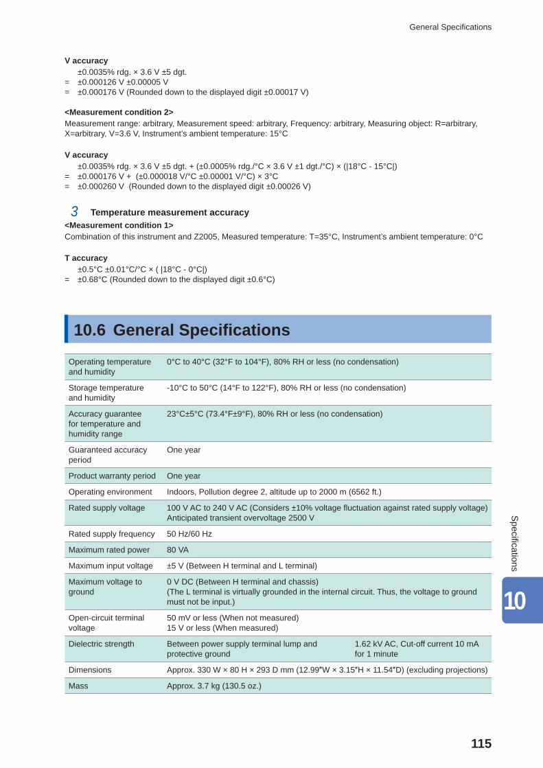
115
General Specifi cations
V accuracy ±0.0035% rdg. × 3.6 V ±5 dgt.= ±0.000126 V ±0.00005 V= ±0.000176 V (Rounded down to the displayed digit ±0.00017 V)
<Measurement condition 2>Measurement range: arbitrary, Measurement speed: arbitrary, Frequency: arbitrary, Measuring object: R=arbitrary, X=arbitrary, V=3.6 V, Instrument’s ambient temperature: 15°C
V accuracy ±0.0035% rdg. × 3.6 V ±5 dgt. + (±0.0005% rdg./°C × 3.6 V ±1 dgt./°C) × (|18°C - 15°C|) = ±0.000176 V + (±0.000018 V/°C ±0.00001 V/°C) × 3°C= ±0.000260 V (Rounded down to the displayed digit ±0.00026 V)
3 Temperature measurement accuracy<Measurement condition 1>Combination of this instrument and Z2005, Measured temperature: T=35°C, Instrument’s ambient temperature: 0°C
T accuracy ±0.5°C ±0.01°C/°C × ( |18°C - 0°C|)= ±0.68°C (Rounded down to the displayed digit ±0.6°C)
10.6 General Specifi cations
Operating temperature and humidity
0°C to 40°C (32°F to 104°F), 80% RH or less (no condensation)
Storage temperature and humidity
-10°C to 50°C (14°F to 122°F), 80% RH or less (no condensation)
Accuracy guarantee for temperature and humidity range
23°C±5°C (73.4°F±9°F), 80% RH or less (no condensation)
Guaranteed accuracy period
One year
Product warranty period One year
Operating environment Indoors, Pollution degree 2, altitude up to 2000 m (6562 ft.)
Rated supply voltage 100 V AC to 240 V AC (Considers ±10% voltage fl uctuation against rated supply voltage)Anticipated transient overvoltage 2500 V
Rated supply frequency 50 Hz/60 Hz
Maximum rated power 80 VA
Maximum input voltage ±5 V (Between H terminal and L terminal)
Maximum voltage to ground
0 V DC (Between H terminal and chassis)(The L terminal is virtually grounded in the internal circuit. Thus, the voltage to ground must not be input.)
Open-circuit terminal voltage
50 mV or less (When not measured)15 V or less (When measured)
Dielectric strength Between power supply terminal lump and protective ground
1.62 kV AC, Cut-off current 10 mA for 1 minute
Dimensions Approx. 330 W × 80 H × 293 D mm (12.99″W × 3.15″H × 11.54″D) (excluding projections)
Mass Approx. 3.7 kg (130.5 oz.)
10
Specifi cations
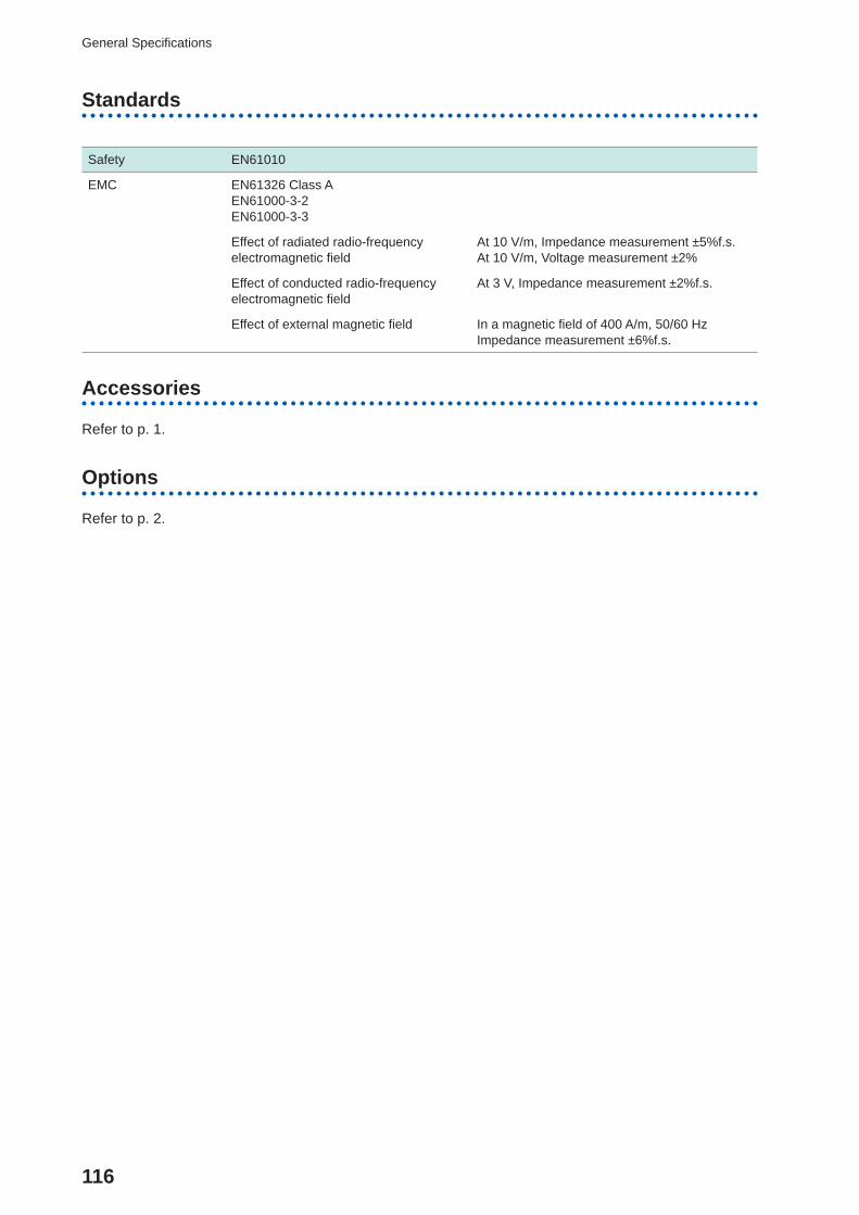
116
General Specifi cations
Standards
Safety EN61010
EMC EN61326 Class AEN61000-3-2EN61000-3-3
Effect of radiated radio-frequency electromagnetic fi eld
At 10 V/m, Impedance measurement ±5%f.s.At 10 V/m, Voltage measurement ±2%
Effect of conducted radio-frequency electromagnetic fi eld
At 3 V, Impedance measurement ±2%f.s.
Effect of external magnetic fi eld In a magnetic fi eld of 400 A/m, 50/60 HzImpedance measurement ±6%f.s.
Accessories
Refer to p. 1.
Options
Refer to p. 2.
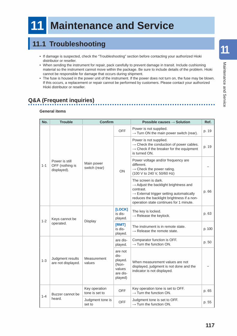
117
11 Maintenance and Service11.1 Troubleshooting
• If damage is suspected, check the “Troubleshooting” section before contacting your authorized Hioki distributor or reseller.
• When sending the instrument for repair, pack carefully to prevent damage in transit. Include cushioning material so the instrument cannot move within the package. Be sure to include details of the problem. Hioki cannot be responsible for damage that occurs during shipment.
• The fuse is housed in the power unit of the instrument. If the power does not turn on, the fuse may be blown. If this occurs, a replacement or repair cannot be performed by customers. Please contact your authorized Hioki distributor or reseller.
Q&A (Frequent inquiries)
General items
No. Trouble Confi rm Possible causes → Solution Ref.
1-1Power is still OFF (nothing is displayed).
Main power switch (rear)
OFF Power is not supplied.→ Turn ON the main power switch (rear). p. 19
ON
Power is not supplied.→ Check the conduction of power cables.→ Check if the breaker for the equipment is turned ON.
p. 19
Power voltage and/or frequency are different.→ Check the power rating.(100 V to 240 V, 50/60 Hz)
−
The screen is dark.→ Adjust the backlight brightness and contrast.→ External trigger setting automatically reduces the backlight brightness if a non-operation state continues for 1 minute.
p. 66
1-2 Keys cannot be operated. Display
[LOCK]is dis-played.
The key is locked.→ Release the keylock. p. 63
[RMT] is dis-played.
The instrument is in remote state.→ Release the remote state. p. 100
1-3 Judgment results are not displayed.
Measurement values
are dis-played.
Comparator function is OFF.→ Turn the function ON. p. 50
are not dis-played.(Non-values are dis-played)
When measurement values are not displayed, judgment is not done and the indicator is not displayed.
−
1-4 Buzzer cannot be heard.
Key operation tone is set to OFF Key operation tone is set to OFF.
→ Turn the function ON. p. 65
Judgment tone is set to OFF Judgment tone is set to OFF.
→ Turn the function ON. p. 55
11
Maintenance and S
ervice
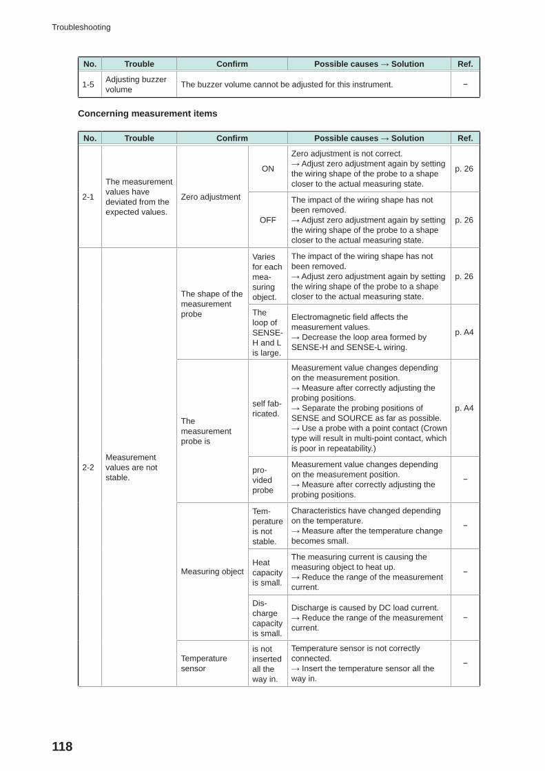
118
Troubleshooting
No. Trouble Confi rm Possible causes → Solution Ref.
1-5 Adjusting buzzer volume The buzzer volume cannot be adjusted for this instrument. −
Concerning measurement items
No. Trouble Confi rm Possible causes → Solution Ref.
2-1
The measurement values have deviated from the expected values.
Zero adjustment
ON
Zero adjustment is not correct.→ Adjust zero adjustment again by setting the wiring shape of the probe to a shape closer to the actual measuring state.
p. 26
OFF
The impact of the wiring shape has not been removed.→ Adjust zero adjustment again by setting the wiring shape of the probe to a shape closer to the actual measuring state.
p. 26
2-2Measurement values are not stable.
The shape of the measurement probe
Varies for each mea-suring object.
The impact of the wiring shape has not been removed.→ Adjust zero adjustment again by setting the wiring shape of the probe to a shape closer to the actual measuring state.
p. 26
The loop of SENSE-H and L is large.
Electromagnetic fi eld affects the measurement values.→ Decrease the loop area formed by SENSE-H and SENSE-L wiring.
p. A4
The measurement probe is
self fab-ricated.
Measurement value changes depending on the measurement position.→ Measure after correctly adjusting the probing positions.→ Separate the probing positions of SENSE and SOURCE as far as possible.→ Use a probe with a point contact (Crown type will result in multi-point contact, which is poor in repeatability.)
p. A4
pro-vided probe
Measurement value changes depending on the measurement position.→ Measure after correctly adjusting the probing positions.
−
Measuring object
Tem-perature is not stable.
Characteristics have changed depending on the temperature.→ Measure after the temperature change becomes small.
−
Heat capacity is small.
The measuring current is causing the measuring object to heat up.→ Reduce the range of the measurement current.
−
Dis-charge capacity is small.
Discharge is caused by DC load current.→ Reduce the range of the measurement current.
−
Temperature sensor
is not inserted all the way in.
Temperature sensor is not correctly connected.→ Insert the temperature sensor all the way in.
−
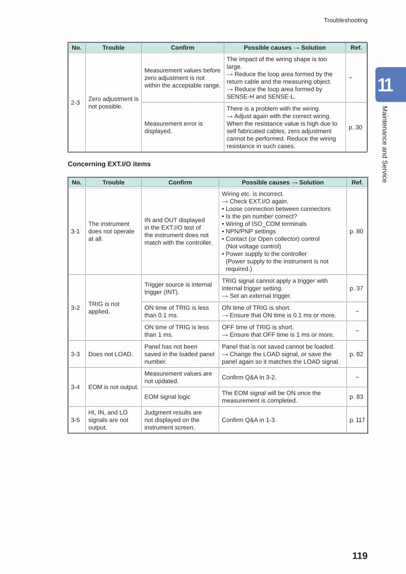
119
Troubleshooting
No. Trouble Confi rm Possible causes → Solution Ref.
2-3 Zero adjustment is not possible.
Measurement values before zero adjustment is not within the acceptable range.
The impact of the wiring shape is too large.→ Reduce the loop area formed by the return cable and the measuring object.→ Reduce the loop area formed by SENSE-H and SENSE-L.
−
Measurement error is displayed.
There is a problem with the wiring.→ Adjust again with the correct wiring. When the resistance value is high due to self fabricated cables, zero adjustment cannot be performed. Reduce the wiring resistance in such cases.
p. 30
Concerning EXT.I/O items
No. Trouble Confi rm Possible causes → Solution Ref.
3-1The instrument does not operate at all.
IN and OUT displayed in the EXT.I/O test of the instrument does not match with the controller.
Wiring etc. is incorrect.→ Check EXT.I/O again. • Loose connection between connectors • Is the pin number correct? • Wiring of ISO_COM terminals • NPN/PNP settings • Contact (or Open collector) control (Not voltage control)
• Power supply to the controller (Power supply to the instrument is not required.)
p. 80
3-2 TRIG is not applied.
Trigger source is internal trigger (INT).
TRIG signal cannot apply a trigger with internal trigger setting.→ Set an external trigger.
p. 37
ON time of TRIG is less than 0.1 ms.
ON time of TRIG is short.→ Ensure that ON time is 0.1 ms or more. −
ON time of TRIG is less than 1 ms.
OFF time of TRIG is short.→ Ensure that OFF time is 1 ms or more. −
3-3 Does not LOAD.Panel has not been saved in the loaded panel number.
Panel that is not saved cannot be loaded.→ Change the LOAD signal, or save the panel again so it matches the LOAD signal.
p. 82
3-4 EOM is not output.
Measurement values are not updated. Confi rm Q&A in 3-2. −
EOM signal logic The EOM signal will be ON once the measurement is completed. p. 83
3-5HI, IN, and LO signals are not output.
Judgment results are not displayed on the instrument screen.
Confi rm Q&A in 1-3. p. 117
11
Maintenance and S
ervice
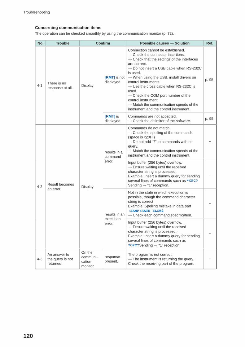
120
Troubleshooting
Concerning communication itemsThe operation can be checked smoothly by using the communication monitor (p. 72).
No. Trouble Confi rm Possible causes → Solution Ref.
4-1 There is no response at all. Display
[RMT] is not displayed.
Connection cannot be established.→ Check the connector insertions.→ Check that the settings of the interfaces are correct.→ Do not insert a USB cable when RS-232C is used.→ When using the USB, install drivers on control instruments.→ Use the cross cable when RS-232C is used.→ Check the COM port number of the control instrument.→ Match the communication speeds of the instrument and the control instrument.
p. 95
[RMT] is displayed.
Commands are not accepted.→ Check the delimiter of the software. p. 95
4-2 Result becomes an error. Display
results in a command error.
Commands do not match.→ Check the spelling of the commands (space is x20H.)→ Do not add “?” to commands with no query.→ Match the communication speeds of the instrument and the control instrument.
−
Input buffer (256 bytes) overfl ow.→ Ensure waiting until the received character string is processed.Example: Insert a dummy query for sending several lines of commands such as *OPC? Sending → “1” reception.
−
results in an execution error.
Not in the state in which execution is possible, though the command character string is correctExample: Spelling mistake in data part:SAMP:RATE SLOW2→ Check each command specifi cation.
−
Input buffer (256 bytes) overfl ow.→ Ensure waiting until the received character string is processed.Example: Insert a dummy query for sending several lines of commands such as *OPC?Sending → “1” reception.
−
4-3An answer to the query is not returned.
On the communi-cation monitor
response present.
The program is not correct.→ The instrument is returning the query. Check the receiving part of the program.
−
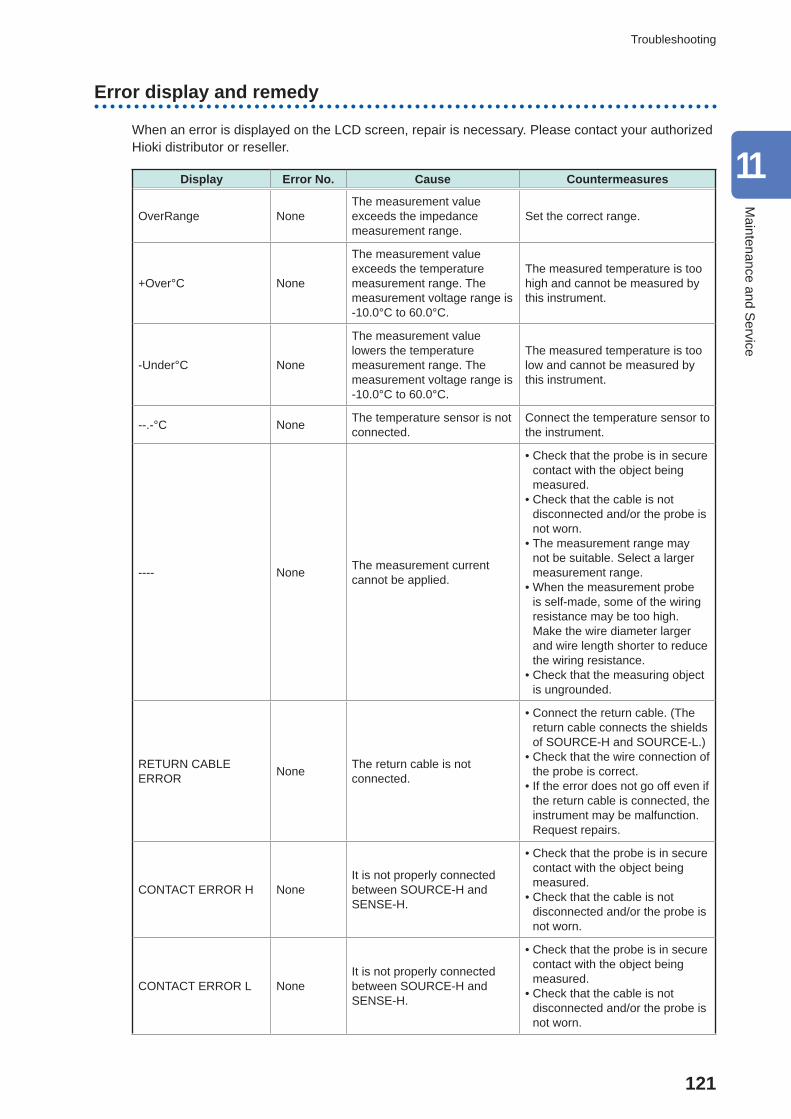
121
Troubleshooting
Error display and remedy
When an error is displayed on the LCD screen, repair is necessary. Please contact your authorized Hioki distributor or reseller.
Display Error No. Cause Countermeasures
OverRange NoneThe measurement value exceeds the impedance measurement range.
Set the correct range.
+Over°C None
The measurement value exceeds the temperature measurement range. The measurement voltage range is -10.0°C to 60.0°C.
The measured temperature is too high and cannot be measured by this instrument.
-Under°C None
The measurement value lowers the temperature measurement range. The measurement voltage range is -10.0°C to 60.0°C.
The measured temperature is too low and cannot be measured by this instrument.
--.-°C None The temperature sensor is not connected.
Connect the temperature sensor to the instrument.
---- None The measurement current cannot be applied.
• Check that the probe is in secure contact with the object being measured.
• Check that the cable is not disconnected and/or the probe is not worn.
• The measurement range may not be suitable. Select a larger measurement range.
• When the measurement probe is self-made, some of the wiring resistance may be too high. Make the wire diameter larger and wire length shorter to reduce the wiring resistance.
• Check that the measuring object is ungrounded.
RETURN CABLE ERROR None The return cable is not
connected.
• Connect the return cable. (The return cable connects the shields of SOURCE-H and SOURCE-L.)
• Check that the wire connection of the probe is correct.
• If the error does not go off even if the return cable is connected, the instrument may be malfunction. Request repairs.
CONTACT ERROR H NoneIt is not properly connected between SOURCE-H and SENSE-H.
• Check that the probe is in secure contact with the object being measured.
• Check that the cable is not disconnected and/or the probe is not worn.
CONTACT ERROR L NoneIt is not properly connected between SOURCE-H and SENSE-H.
• Check that the probe is in secure contact with the object being measured.
• Check that the cable is not disconnected and/or the probe is not worn.
11
Maintenance and S
ervice
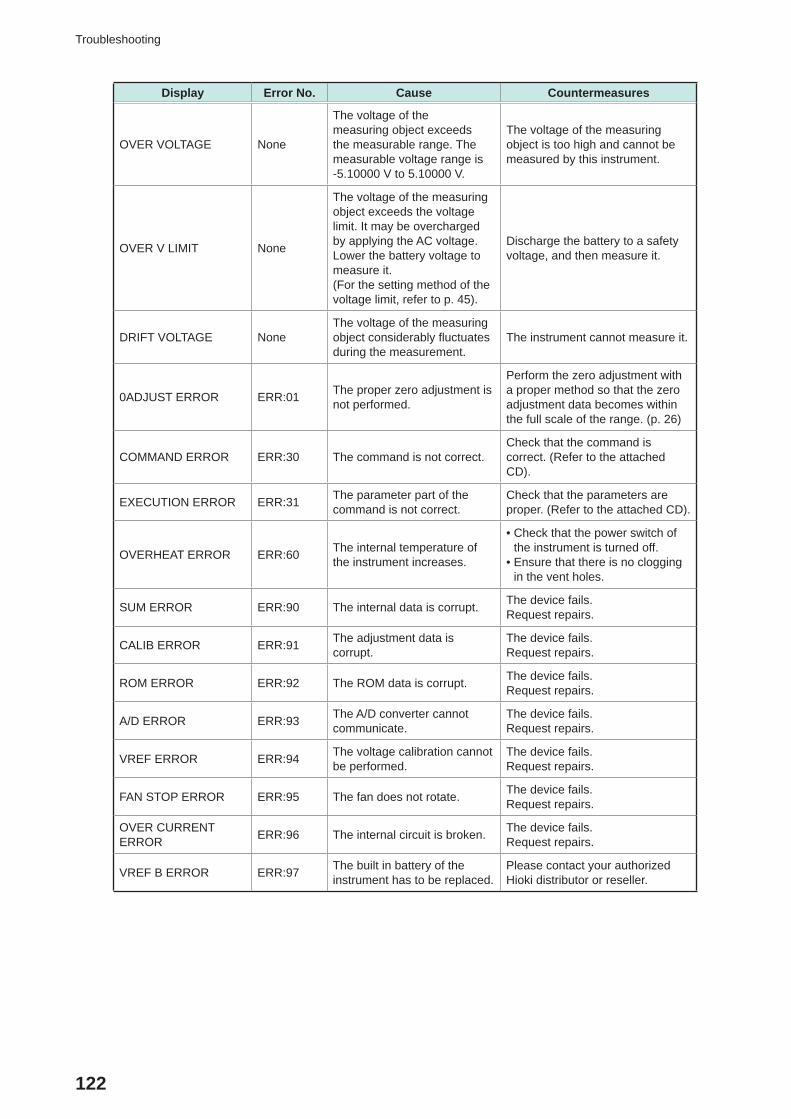
122
Troubleshooting
Display Error No. Cause Countermeasures
OVER VOLTAGE None
The voltage of the measuring object exceeds the measurable range. The measurable voltage range is -5.10000 V to 5.10000 V.
The voltage of the measuring object is too high and cannot be measured by this instrument.
OVER V LIMIT None
The voltage of the measuring object exceeds the voltage limit. It may be overcharged by applying the AC voltage. Lower the battery voltage to measure it.(For the setting method of the voltage limit, refer to p. 45).
Discharge the battery to a safety voltage, and then measure it.
DRIFT VOLTAGE NoneThe voltage of the measuring object considerably fl uctuates during the measurement.
The instrument cannot measure it.
0ADJUST ERROR ERR:01 The proper zero adjustment is not performed.
Perform the zero adjustment with a proper method so that the zero adjustment data becomes within the full scale of the range. (p. 26)
COMMAND ERROR ERR:30 The command is not correct.Check that the command is correct. (Refer to the attached CD).
EXECUTION ERROR ERR:31 The parameter part of the command is not correct.
Check that the parameters are proper. (Refer to the attached CD).
OVERHEAT ERROR ERR:60 The internal temperature of the instrument increases.
• Check that the power switch of the instrument is turned off.
• Ensure that there is no clogging in the vent holes.
SUM ERROR ERR:90 The internal data is corrupt. The device fails. Request repairs.
CALIB ERROR ERR:91 The adjustment data is corrupt.
The device fails. Request repairs.
ROM ERROR ERR:92 The ROM data is corrupt. The device fails. Request repairs.
A/D ERROR ERR:93 The A/D converter cannot communicate.
The device fails. Request repairs.
VREF ERROR ERR:94 The voltage calibration cannot be performed.
The device fails. Request repairs.
FAN STOP ERROR ERR:95 The fan does not rotate. The device fails.Request repairs.
OVER CURRENT ERROR ERR:96 The internal circuit is broken. The device fails.
Request repairs.
VREF B ERROR ERR:97 The built in battery of the instrument has to be replaced.
Please contact your authorized Hioki distributor or reseller.
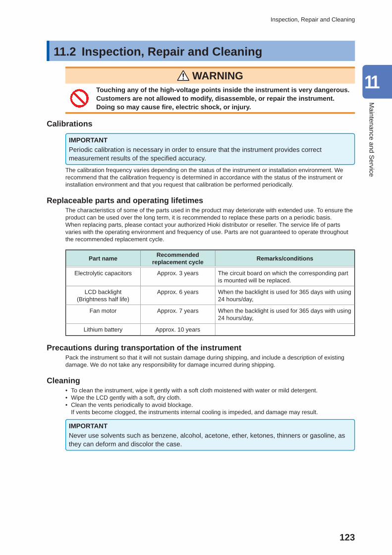
123
Inspection, Repair and Cleaning
11.2 Inspection, Repair and Cleaning
WARNING Touching any of the high-voltage points inside the instrument is very dangerous. Customers are not allowed to modify, disassemble, or repair the instrument. Doing so may cause fi re, electric shock, or injury.
Calibrations
IMPORTANTPeriodic calibration is necessary in order to ensure that the instrument provides correct measurement results of the specifi ed accuracy.
The calibration frequency varies depending on the status of the instrument or installation environment. We recommend that the calibration frequency is determined in accordance with the status of the instrument or installation environment and that you request that calibration be performed periodically.
Replaceable parts and operating lifetimesThe characteristics of some of the parts used in the product may deteriorate with extended use. To ensure the product can be used over the long term, it is recommended to replace these parts on a periodic basis.When replacing parts, please contact your authorized Hioki distributor or reseller. The service life of parts varies with the operating environment and frequency of use. Parts are not guaranteed to operate throughout the recommended replacement cycle.
Part name Recommended replacement cycle Remarks/conditions
Electrolytic capacitors Approx. 3 years The circuit board on which the corresponding part is mounted will be replaced.
LCD backlight(Brightness half life)
Approx. 6 years When the backlight is used for 365 days with using 24 hours/day,
Fan motor Approx. 7 years When the backlight is used for 365 days with using 24 hours/day,
Lithium battery Approx. 10 years
Precautions during transportation of the instrument Pack the instrument so that it will not sustain damage during shipping, and include a description of existing damage. We do not take any responsibility for damage incurred during shipping.
Cleaning • To clean the instrument, wipe it gently with a soft cloth moistened with water or mild detergent. • Wipe the LCD gently with a soft, dry cloth. • Clean the vents periodically to avoid blockage.
If vents become clogged, the instruments internal cooling is impeded, and damage may result.
IMPORTANTNever use solvents such as benzene, alcohol, acetone, ether, ketones, thinners or gasoline, as they can deform and discolor the case.
11
Maintenance and S
ervice
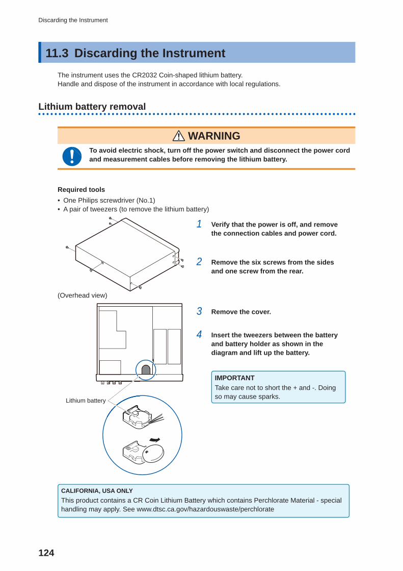
124
Discarding the Instrument
11.3 Discarding the Instrument The instrument uses the CR2032 Coin-shaped lithium battery. Handle and dispose of the instrument in accordance with local regulations.
Lithium battery removal
WARNING To avoid electric shock, turn off the power switch and disconnect the power cord and measurement cables before removing the lithium battery.
Required tools • One Philips screwdriver (No.1) • A pair of tweezers (to remove the lithium battery)
1 Verify that the power is off, and remove the connection cables and power cord.
2 Remove the six screws from the sides and one screw from the rear.
(Overhead view)
Lithium battery
3 Remove the cover.
4 Insert the tweezers between the battery and battery holder as shown in the diagram and lift up the battery.
IMPORTANTTake care not to short the + and -. Doing so may cause sparks.
CALIFORNIA, USA ONLYThis product contains a CR Coin Lithium Battery which contains Perchlorate Material - special handling may apply. See www.dtsc.ca.gov/hazardouswaste/perchlorate
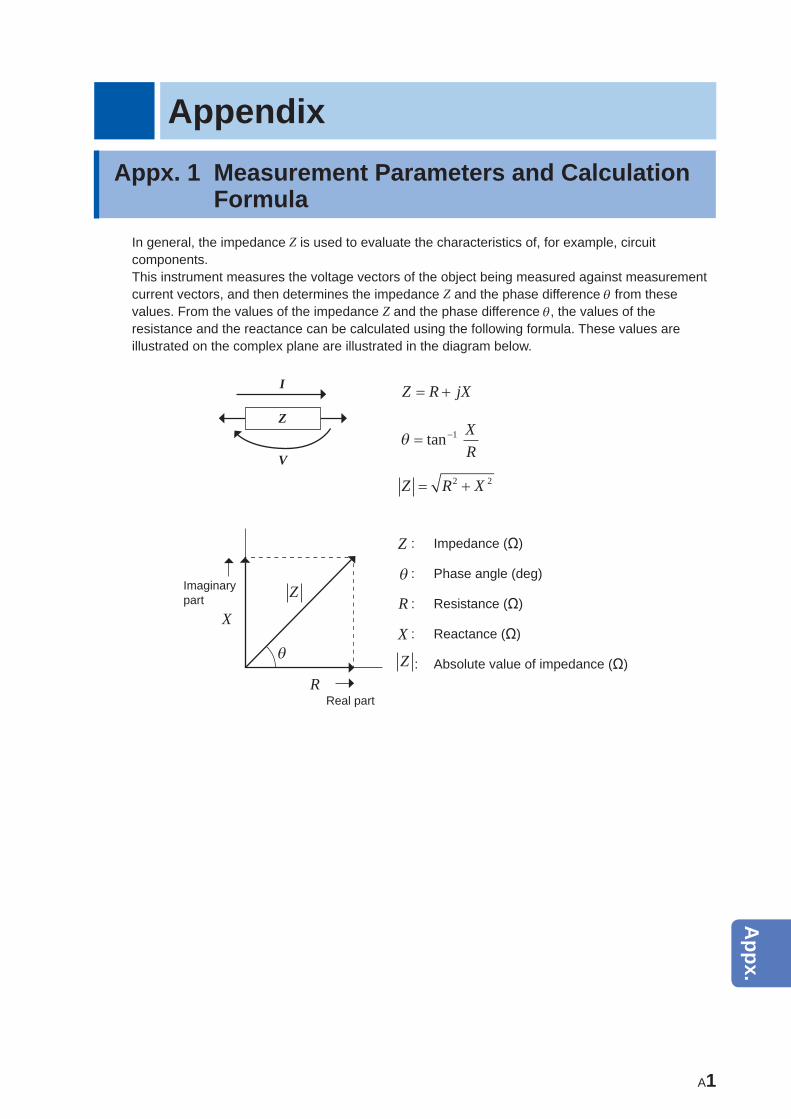
A1
AppendixAppx. 1 Measurement Parameters and Calculation
FormulaIn general, the impedance Z is used to evaluate the characteristics of, for example, circuit components.This instrument measures the voltage vectors of the object being measured against measurement current vectors, and then determines the impedance Z and the phase difference from these values. From the values of the impedance Z and the phase difference , the values of the resistance and the reactance can be calculated using the following formula. These values are illustrated on the complex plane are illustrated in the diagram below.
Z
I
V
Z R jX
tan 1 XR
Z R X2 2
Imaginary part
jX
Z
RReal part
Z : Impedance (Ω)
: Phase angle (deg)
R : Resistance (Ω)
X : Reactance (Ω)
Z : Absolute value of impedance (Ω)
10
9
8
7
6
5
4
3
2
1
Appx.
Ind.
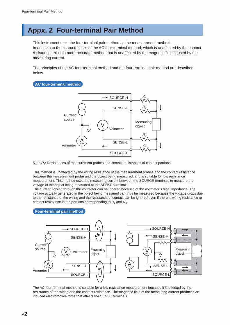
A2
Four-terminal Pair Method
Appx. 2 Four-terminal Pair MethodThis instrument uses the four-terminal pair method as the measurement method.In addition to the characteristics of the AC four-terminal method, which is unaffected by the contact resistance, this is a more accurate method that is unaffected by the magnetic fi eld caused by the measuring current.
The principles of the AC four-terminal method and the four-terminal pair method are described below.
AC four-terminal method
R1
R2
R3
R4
Measuring objectV
A
SOURCE-H
SOURCE-L
SENSE-H
SENSE-LAmmeter
Current source
Voltmeter
R1 to R4: Resistances of measurement probes and contact resistances of contact portions
This method is unaffected by the wiring resistance of the measurement probes and the contact resistance between the measurement probe and the object being measured, and is suitable for low resistance measurement. This method uses the measuring current between the SOURCE terminals to measure the voltage of the object being measured at the SENSE terminals.The current fl owing through the voltmeter can be ignored because of the voltmeter’s high impedance. The voltage actually generated in the object being measured can thus be measured because the voltage drops due to the resistance of the wiring and the resistance of contact can be ignored even if there is wiring resistance or contact resistance in the portions corresponding to R2 and R3.
Four-terminal pair method
Measuring object
SOURCE-H
SOURCE-L
SENSE-L
SENSE-H
V
A
Current source
Ammeter
VoltmeterMeasuring objectV
A
SOURCE-H
SENSE-H
SENSE-L
SOURCE-L
The AC four-terminal method is suitable for a low resistance measurement because it is affected by the resistance of the wiring and the contact resistance. The magnetic fi eld of the measuring current produces an induced electromotive force that affects the SENSE terminals.
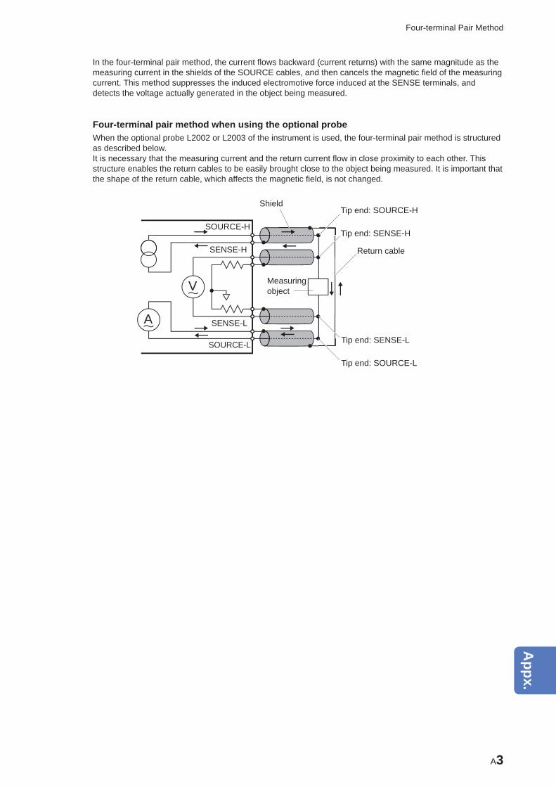
A3
Four-terminal Pair Method
In the four-terminal pair method, the current fl ows backward (current returns) with the same magnitude as the measuring current in the shields of the SOURCE cables, and then cancels the magnetic fi eld of the measuring current. This method suppresses the induced electromotive force induced at the SENSE terminals, and detects the voltage actually generated in the object being measured.
Four-terminal pair method when using the optional probeWhen the optional probe L2002 or L2003 of the instrument is used, the four-terminal pair method is structured as described below.It is necessary that the measuring current and the return current fl ow in close proximity to each other. This structure enables the return cables to be easily brought close to the object being measured. It is important that the shape of the return cable, which affects the magnetic fi eld, is not changed.
Measuring object
SOURCE-H
SOURCE-L
SENSE-L
SENSE-H
V
A
ShieldTip end: SOURCE-H
Tip end: SENSE-H
Return cable
Tip end: SENSE-L
Tip end: SOURCE-L
10
9
8
7
6
5
4
3
2
1
Appx.
Ind.
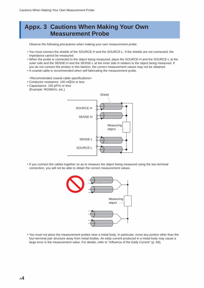
A4
Cautions When Making Your Own Measurement Probe
Appx. 3 Cautions When Making Your Own Measurement Probe
Observe the following precautions when making your own measurement probe.
• You must connect the shields of the SOURCE-H and the SOURCE-L. If the shields are not connected, the impedance cannot be measured.
• When the probe is connected to the object being measured, place the SOURCE-H and the SOURCE-L at the outer side and the SENSE-H and the SENSE-L at the inner side in relation to the object being measured. If you do not connect the probes in this fashion, the correct measurement values may not be obtained.
• A coaxial cable is recommended when self fabricating the measurement probe.
<Recommended coaxial cable specifi cations> • Conductor resistance: 150 mΩ/m or less • Capacitance: 150 pF/m or less(Example: RG58A/U, etc.)
Measuring object
SOURCE-H
SOURCE-L
SENSE-L
SENSE-H
Shield
• If you connect the cables together so as to measure the object being measured using the two-terminal connection, you will not be able to obtain the correct measurement values.
Measuring object
• You must not place the measurement probes near a metal body. In particular, move any portion other than the four-terminal pair structure away from metal bodies. An eddy current produced in a metal body may cause a large error in the measurement value. For details, refer to “Infl uence of the Eddy Current” (p. A8).
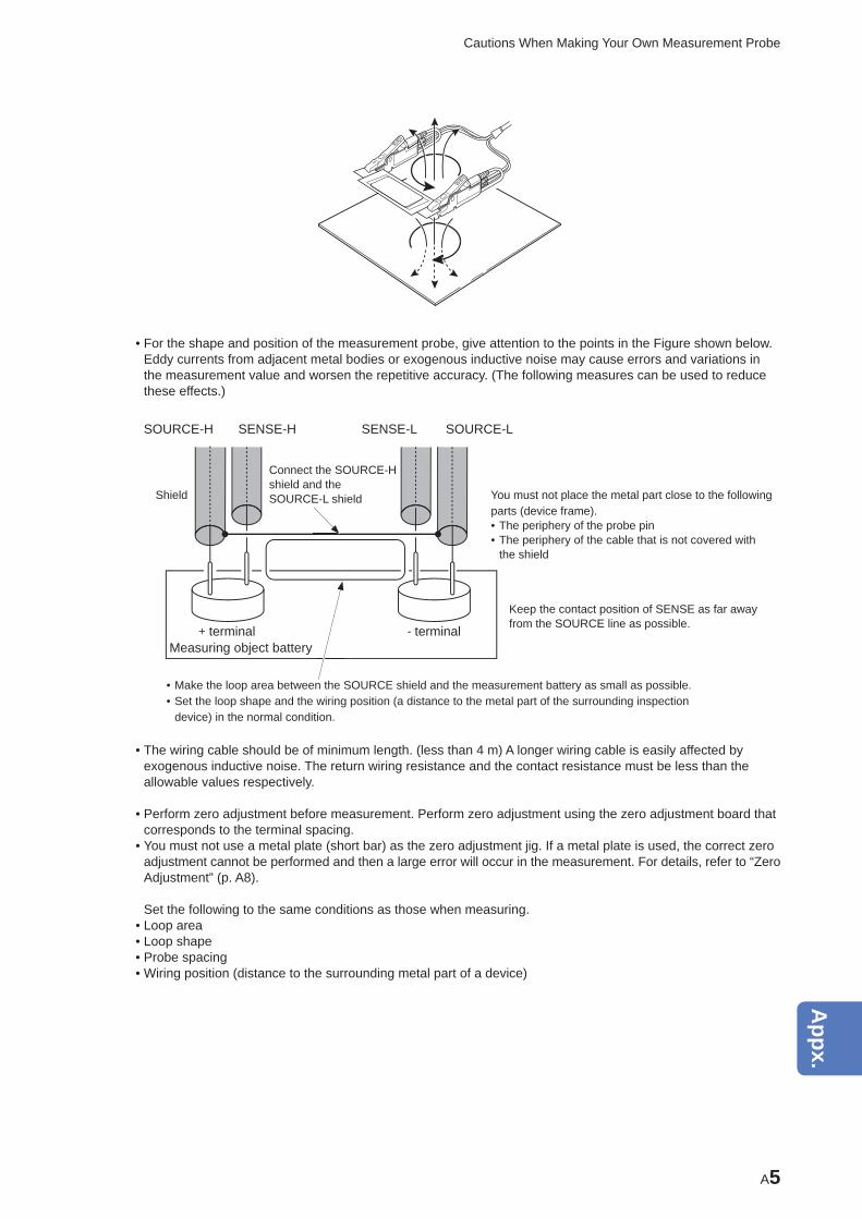
A5
Cautions When Making Your Own Measurement Probe
• For the shape and position of the measurement probe, give attention to the points in the Figure shown below. Eddy currents from adjacent metal bodies or exogenous inductive noise may cause errors and variations in the measurement value and worsen the repetitive accuracy. (The following measures can be used to reduce these effects.)
SOURCE-H SOURCE-LSENSE-LSENSE-H
Connect the SOURCE-H shield and the SOURCE-L shield
• Make the loop area between the SOURCE shield and the measurement battery as small as possible. • Set the loop shape and the wiring position (a distance to the metal part of the surrounding inspection device) in the normal condition.
Measuring object battery+ terminal - terminal
Shield You must not place the metal part close to the following parts (device frame). • The periphery of the probe pin • The periphery of the cable that is not covered with the shield
Keep the contact position of SENSE as far away from the SOURCE line as possible.
• The wiring cable should be of minimum length. (less than 4 m) A longer wiring cable is easily affected by exogenous inductive noise. The return wiring resistance and the contact resistance must be less than the allowable values respectively.
• Perform zero adjustment before measurement. Perform zero adjustment using the zero adjustment board that corresponds to the terminal spacing.
• You must not use a metal plate (short bar) as the zero adjustment jig. If a metal plate is used, the correct zero adjustment cannot be performed and then a large error will occur in the measurement. For details, refer to “Zero Adjustment” (p. A8).
Set the following to the same conditions as those when measuring. • Loop area • Loop shape • Probe spacing • Wiring position (distance to the surrounding metal part of a device)
10
9
8
7
6
5
4
3
2
1
Appx.
Ind.
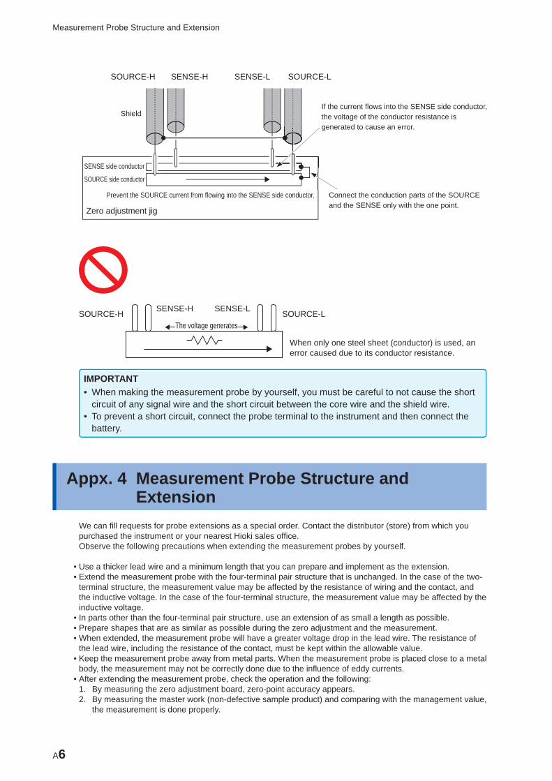
A6
Measurement Probe Structure and Extension
SOURCE-H SOURCE-LSENSE-LSENSE-H
Shield
SENSE side conductor
SOURCE side conductor
Zero adjustment jig
Prevent the SOURCE current from flowing into the SENSE side conductor.
If the current flows into the SENSE side conductor, the voltage of the conductor resistance is generated to cause an error.
Connect the conduction parts of the SOURCE and the SENSE only with the one point.
SOURCE-H SOURCE-LSENSE-LSENSE-H
The voltage generates
When only one steel sheet (conductor) is used, an error caused due to its conductor resistance.
IMPORTANT • When making the measurement probe by yourself, you must be careful to not cause the short circuit of any signal wire and the short circuit between the core wire and the shield wire.
• To prevent a short circuit, connect the probe terminal to the instrument and then connect the battery.
Appx. 4 Measurement Probe Structure and Extension
We can fi ll requests for probe extensions as a special order. Contact the distributor (store) from which you purchased the instrument or your nearest Hioki sales offi ce.Observe the following precautions when extending the measurement probes by yourself.
• Use a thicker lead wire and a minimum length that you can prepare and implement as the extension. • Extend the measurement probe with the four-terminal pair structure that is unchanged. In the case of the two-terminal structure, the measurement value may be affected by the resistance of wiring and the contact, and the inductive voltage. In the case of the four-terminal structure, the measurement value may be affected by the inductive voltage.
• In parts other than the four-terminal pair structure, use an extension of as small a length as possible. • Prepare shapes that are as similar as possible during the zero adjustment and the measurement. • When extended, the measurement probe will have a greater voltage drop in the lead wire. The resistance of the lead wire, including the resistance of the contact, must be kept within the allowable value.
• Keep the measurement probe away from metal parts. When the measurement probe is placed close to a metal body, the measurement may not be correctly done due to the infl uence of eddy currents.
• After extending the measurement probe, check the operation and the following:1. By measuring the zero adjustment board, zero-point accuracy appears.2. By measuring the master work (non-defective sample product) and comparing with the management value,
the measurement is done properly.
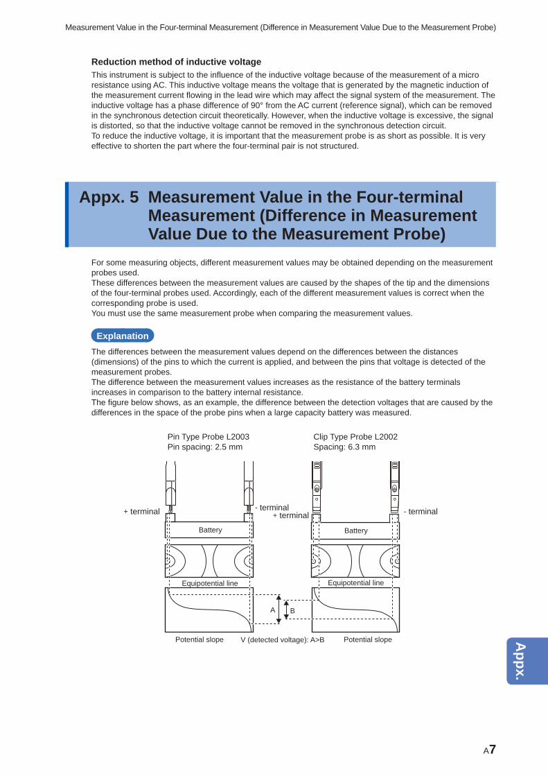
A7
Measurement Value in the Four-terminal Measurement (Difference in Measurement Value Due to the Measurement Probe)
Reduction method of inductive voltageThis instrument is subject to the infl uence of the inductive voltage because of the measurement of a micro resistance using AC. This inductive voltage means the voltage that is generated by the magnetic induction of the measurement current fl owing in the lead wire which may affect the signal system of the measurement. The inductive voltage has a phase difference of 90° from the AC current (reference signal), which can be removed in the synchronous detection circuit theoretically. However, when the inductive voltage is excessive, the signal is distorted, so that the inductive voltage cannot be removed in the synchronous detection circuit.To reduce the inductive voltage, it is important that the measurement probe is as short as possible. It is very effective to shorten the part where the four-terminal pair is not structured.
Appx. 5 Measurement Value in the Four-terminal Measurement (Difference in Measurement Value Due to the Measurement Probe)
For some measuring objects, different measurement values may be obtained depending on the measurement probes used.These differences between the measurement values are caused by the shapes of the tip and the dimensions of the four-terminal probes used. Accordingly, each of the different measurement values is correct when the corresponding probe is used.You must use the same measurement probe when comparing the measurement values.
ExplanationThe differences between the measurement values depend on the differences between the distances (dimensions) of the pins to which the current is applied, and between the pins that voltage is detected of the measurement probes.The difference between the measurement values increases as the resistance of the battery terminals increases in comparison to the battery internal resistance.The fi gure below shows, as an example, the difference between the detection voltages that are caused by the differences in the space of the probe pins when a large capacity battery was measured.
Pin Type Probe L2003Pin spacing: 2.5 mm
Clip Type Probe L2002 Spacing: 6.3 mm
+ terminal + terminal- terminal - terminal
Battery Battery
Equipotential line
Potential slope Potential slope
Equipotential line
A B
V (detected voltage): A>B
10
9
8
7
6
5
4
3
2
1
Appx.
Ind.
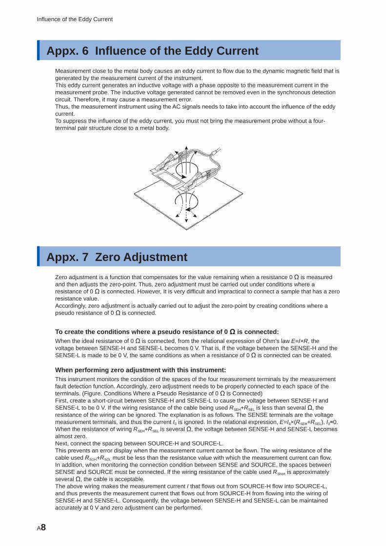
A8
Infl uence of the Eddy Current
Appx. 6 Infl uence of the Eddy CurrentMeasurement close to the metal body causes an eddy current to fl ow due to the dynamic magnetic fi eld that is generated by the measurement current of the instrument.This eddy current generates an inductive voltage with a phase opposite to the measurement current in the measurement probe. The inductive voltage generated cannot be removed even in the synchronous detection circuit. Therefore, it may cause a measurement error.Thus, the measurement instrument using the AC signals needs to take into account the infl uence of the eddy current.To suppress the infl uence of the eddy current, you must not bring the measurement probe without a four-terminal pair structure close to a metal body.
Appx. 7 Zero AdjustmentZero adjustment is a function that compensates for the value remaining when a resistance 0 Ω is measured and then adjusts the zero-point. Thus, zero adjustment must be carried out under conditions where a resistance of 0 Ω is connected. However, It is very diffi cult and impractical to connect a sample that has a zero resistance value.Accordingly, zero adjustment is actually carried out to adjust the zero-point by creating conditions where a pseudo resistance of 0 Ω is connected.
To create the conditions where a pseudo resistance of 0 Ω is connected:When the ideal resistance of 0 Ω is connected, from the relational expression of Ohm’s law E=I×R, the voltage between SENSE-H and SENSE-L becomes 0 V. That is, if the voltage between the SENSE-H and the SENSE-L is made to be 0 V, the same conditions as when a resistance of 0 Ω is connected can be created.
When performing zero adjustment with this instrument:This instrument monitors the condition of the spaces of the four measurement terminals by the measurement fault detection function. Accordingly, zero adjustment needs to be properly connected to each space of the terminals. (Figure. Conditions Where a Pseudo Resistance of 0 Ω is Connected)First, create a short-circuit between SENSE-H and SENSE-L to cause the voltage between SENSE-H and SENSE-L to be 0 V. If the wiring resistance of the cable being used RSEH+RSEL is less than several Ω, the resistance of the wiring can be ignored. The explanation is as follows. The SENSE terminals are the voltage measurement terminals, and thus the current I0 is ignored. In the relational expression, E=I0×(RSEH+RSEL), I0≈0. When the resistance of wiring RSEH+RSEL is several Ω, the voltage between SENSE-H and SENSE-L becomes almost zero.Next, connect the spacing between SOURCE-H and SOURCE-L.This prevents an error display when the measurement current cannot be fl own. The wiring resistance of the cable used RSOH+RSOL must be less than the resistance value with which the measurement current can fl ow. In addition, when monitoring the connection condition between SENSE and SOURCE, the spaces between SENSE and SOURCE must be connected. If the wiring resistance of the cable used RShort is approximately several Ω, the cable is acceptable.The above wiring makes the measurement current I that fl ows out from SOURCE-H fl ow into SOURCE-L, and thus prevents the measurement current that fl ows out from SOURCE-H from fl owing into the wiring of SENSE-H and SENSE-L. Consequently, the voltage between SENSE-H and SENSE-L can be maintained accurately at 0 V and zero adjustment can be performed.
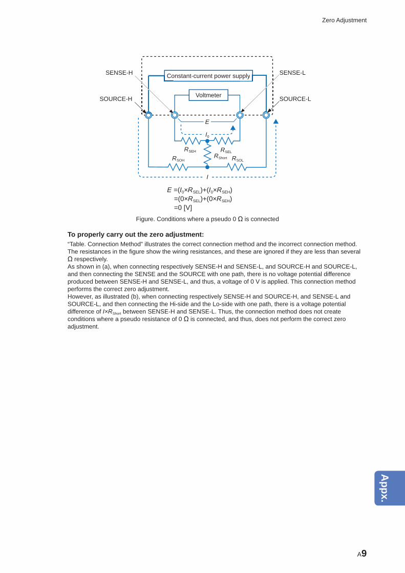
A9
Zero Adjustment
Constant-current power supply
VoltmeterSOURCE-H
CoSENSE-H pply SENSE-L
SOURCE-L
E
I0
RSEH
RSOH RSOL
RSELRShort
I
E =(I0×RSEL)+(I0×RSEH) =(0×RSEL)+(0×RSEH) =0 [V]
Figure. Conditions where a pseudo 0 Ω is connected
To properly carry out the zero adjustment:“Table. Connection Method” illustrates the correct connection method and the incorrect connection method. The resistances in the fi gure show the wiring resistances, and these are ignored if they are less than several Ω respectively.As shown in (a), when connecting respectively SENSE-H and SENSE-L, and SOURCE-H and SOURCE-L, and then connecting the SENSE and the SOURCE with one path, there is no voltage potential difference produced between SENSE-H and SENSE-L, and thus, a voltage of 0 V is applied. This connection method performs the correct zero adjustment.However, as illustrated (b), when connecting respectively SENSE-H and SOURCE-H, and SENSE-L and SOURCE-L, and then connecting the Hi-side and the Lo-side with one path, there is a voltage potential difference of I×RShort between SENSE-H and SENSE-L. Thus, the connection method does not create conditions where a pseudo resistance of 0 Ω is connected, and thus, does not perform the correct zero adjustment.
10
9
8
7
6
5
4
3
2
1
Appx.
Ind.
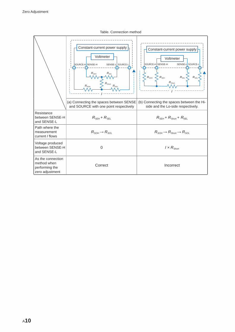
A10
Zero Adjustment
Table. Connection method
RSEH
RSOH RSOL
RSEL
RShort
I
Constant-current power supply
Voltmeter
SOURCE-H SENSE-H SENSE-L SOURCE-L
RSEHRSOH RSOLRSEL
RShort
I
Constant-current power supply
VoltmeterSOURCE-H SENSE-H SENSE-L SOURCE-L
(a) Connecting the spaces between SENSE and SOURCE with one point respectively
(b) Connecting the spaces between the Hi-side and the Lo-side respectively.
Resistance between SENSE-H and SENSE-L
RSEH + RSEL RSEH + RShort + RSEL
Path where the measurement current I fl ows
RSOH → RSOL RSOH → RShort → RSOL
Voltage produced between SENSE-H and SENSE-L
0 I × RShort
As the connection method when performing the zero adjustment
Correct Incorrect
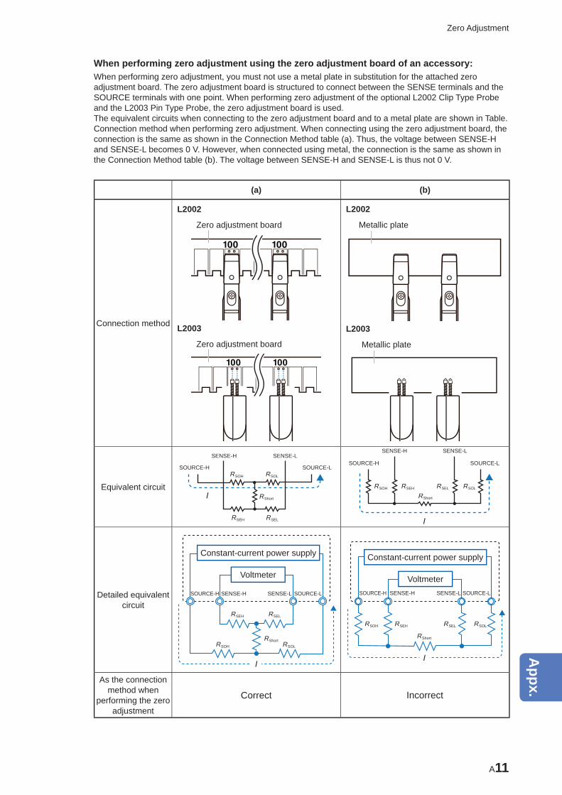
A11
Zero Adjustment
When performing zero adjustment using the zero adjustment board of an accessory:When performing zero adjustment, you must not use a metal plate in substitution for the attached zero adjustment board. The zero adjustment board is structured to connect between the SENSE terminals and the SOURCE terminals with one point. When performing zero adjustment of the optional L2002 Clip Type Probe and the L2003 Pin Type Probe, the zero adjustment board is used.The equivalent circuits when connecting to the zero adjustment board and to a metal plate are shown in Table. Connection method when performing zero adjustment. When connecting using the zero adjustment board, the connection is the same as shown in the Connection Method table (a). Thus, the voltage between SENSE-H and SENSE-L becomes 0 V. However, when connected using metal, the connection is the same as shown in the Connection Method table (b). The voltage between SENSE-H and SENSE-L is thus not 0 V.
(a) (b)
Connection method
L2002
Zero adjustment board
L2003
Zero adjustment board
L2002
Metallic plate
L2003
Metallic plate
Equivalent circuitRSOL
RSEH
RSOH
RSEL
RShortI
SOURCE-H
SENSE-H SENSE-L
SOURCE-L
RSOLRSEHRSOH RSEL
RShort
I
SOURCE-H
SENSE-H SENSE-L
SOURCE-L
Detailed equivalent circuit
RSEH
RSOH RSOL
RSEL
RShort
I
Constant-current power supply
Voltmeter
SOURCE-H SENSE-H SENSE-L SOURCE-L
RSEHRSOH RSOLRSEL
RShort
I
Constant-current power supply
VoltmeterSOURCE-H SENSE-H SENSE-L SOURCE-L
As the connection method when
performing the zero adjustment
Correct Incorrect
10
9
8
7
6
5
4
3
2
1
Appx.
Ind.
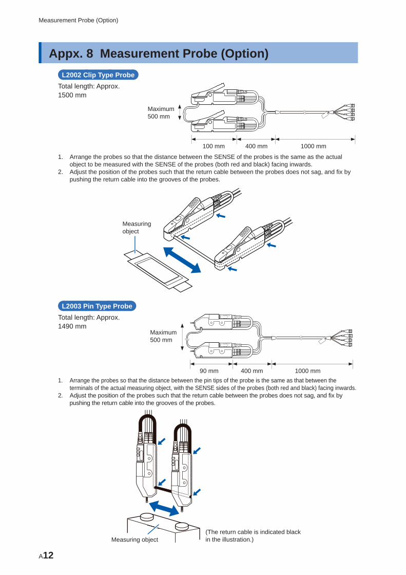
A12
Measurement Probe (Option)
Appx. 8 Measurement Probe (Option)L2002 Clip Type Probe
Total length: Approx. 1500 mm
100 mm 400 mm 1000 mm
Maximum 500 mm
1. Arrange the probes so that the distance between the SENSE of the probes is the same as the actual object to be measured with the SENSE of the probes (both red and black) facing inwards.
2. Adjust the position of the probes such that the return cable between the probes does not sag, and fi x by pushing the return cable into the grooves of the probes.
Measuring object
L2003 Pin Type ProbeTotal length: Approx. 1490 mm
90 mm 400 mm
Maximum 500 mm
1000 mm1. Arrange the probes so that the distance between the pin tips of the probe is the same as that between the
terminals of the actual measuring object, with the SENSE sides of the probes (both red and black) facing inwards.2. Adjust the position of the probes such that the return cable between the probes does not sag, and fi x by
pushing the return cable into the grooves of the probes.
Measuring object(The return cable is indicated black in the illustration.)
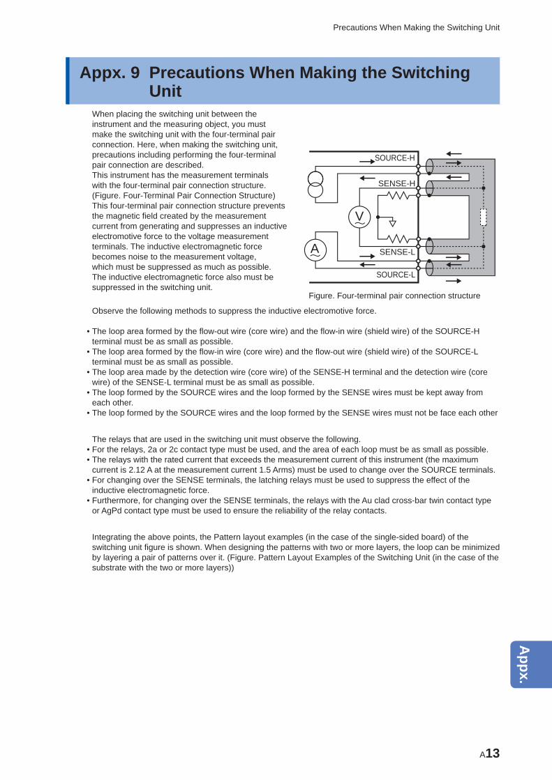
A13
Precautions When Making the Switching Unit
Appx. 9 Precautions When Making the Switching Unit
When placing the switching unit between the instrument and the measuring object, you must make the switching unit with the four-terminal pair connection. Here, when making the switching unit, precautions including performing the four-terminal pair connection are described.This instrument has the measurement terminals with the four-terminal pair connection structure. (Figure. Four-Terminal Pair Connection Structure) This four-terminal pair connection structure prevents the magnetic fi eld created by the measurement current from generating and suppresses an inductive electromotive force to the voltage measurement terminals. The inductive electromagnetic force becomes noise to the measurement voltage, which must be suppressed as much as possible. The inductive electromagnetic force also must be suppressed in the switching unit.
V
A
SOURCE-H
SENSE-H
SENSE-L
SOURCE-L
Figure. Four-terminal pair connection structure
Observe the following methods to suppress the inductive electromotive force.
• The loop area formed by the fl ow-out wire (core wire) and the fl ow-in wire (shield wire) of the SOURCE-H terminal must be as small as possible.
• The loop area formed by the fl ow-in wire (core wire) and the fl ow-out wire (shield wire) of the SOURCE-L terminal must be as small as possible.
• The loop area made by the detection wire (core wire) of the SENSE-H terminal and the detection wire (core wire) of the SENSE-L terminal must be as small as possible.
• The loop formed by the SOURCE wires and the loop formed by the SENSE wires must be kept away from each other.
• The loop formed by the SOURCE wires and the loop formed by the SENSE wires must not be face each other
The relays that are used in the switching unit must observe the following. • For the relays, 2a or 2c contact type must be used, and the area of each loop must be as small as possible. • The relays with the rated current that exceeds the measurement current of this instrument (the maximum current is 2.12 A at the measurement current 1.5 Arms) must be used to change over the SOURCE terminals.
• For changing over the SENSE terminals, the latching relays must be used to suppress the effect of the inductive electromagnetic force.
• Furthermore, for changing over the SENSE terminals, the relays with the Au clad cross-bar twin contact type or AgPd contact type must be used to ensure the reliability of the relay contacts.
Integrating the above points, the Pattern layout examples (in the case of the single-sided board) of the switching unit fi gure is shown. When designing the patterns with two or more layers, the loop can be minimized by layering a pair of patterns over it. (Figure. Pattern Layout Examples of the Switching Unit (in the case of the substrate with the two or more layers))
10
9
8
7
6
5
4
3
2
1
Appx.
Ind.
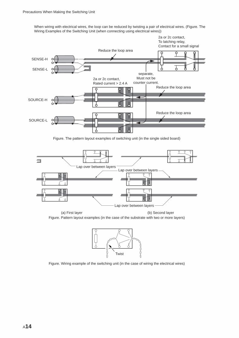
A14
Precautions When Making the Switching Unit
When wiring with electrical wires, the loop can be reduced by twisting a pair of electrical wires. (Figure. The Wiring Examples of the Switching Unit (when connecting using electrical wires))
Reduce the loop area
SENSE-H
SOURCE-H
SOURCE-L
SENSE-L
2a or 2c contact,Rated current > 2.4 A
separate,Must not be
counter current.Reduce the loop area
Reduce the loop area
2a or 2c contact,To latching relay,Contact for a small signal
Figure. The pattern layout examples of switching unit (in the single sided board)
Lap over between layersLap over between layers
Lap over between layers
(a) First layer (b) Second layerFigure. Pattern layout examples (in the case of the substrate with two or more layers)
Twist
Figure. Wiring example of the switching unit (in the case of wiring the electrical wires)
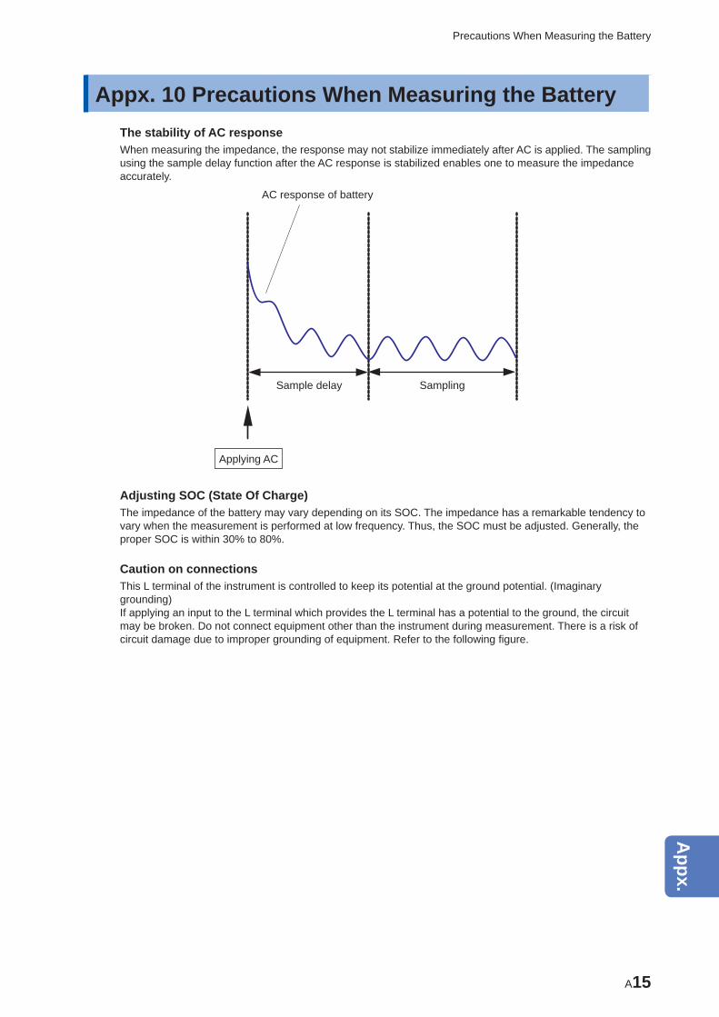
A15
Precautions When Measuring the Battery
Appx. 10 Precautions When Measuring the BatteryThe stability of AC responseWhen measuring the impedance, the response may not stabilize immediately after AC is applied. The sampling using the sample delay function after the AC response is stabilized enables one to measure the impedance accurately.
Sample delay Sampling
Applying AC
AC response of battery
Adjusting SOC (State Of Charge)The impedance of the battery may vary depending on its SOC. The impedance has a remarkable tendency to vary when the measurement is performed at low frequency. Thus, the SOC must be adjusted. Generally, the proper SOC is within 30% to 80%.
Caution on connectionsThis L terminal of the instrument is controlled to keep its potential at the ground potential. (Imaginary grounding)If applying an input to the L terminal which provides the L terminal has a potential to the ground, the circuit may be broken. Do not connect equipment other than the instrument during measurement. There is a risk of circuit damage due to improper grounding of equipment. Refer to the following fi gure.
10
9
8
7
6
5
4
3
2
1
Appx.
Ind.
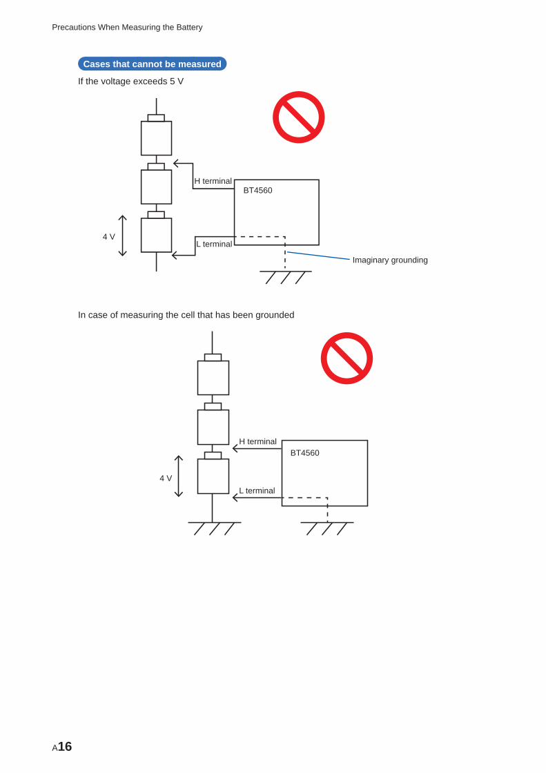
A16
Precautions When Measuring the Battery
Cases that cannot be measured
If the voltage exceeds 5 V
Imaginary grounding
4 V
H terminal
L terminal
BT4560
In case of measuring the cell that has been grounded
4 V
H terminal
L terminal
BT4560
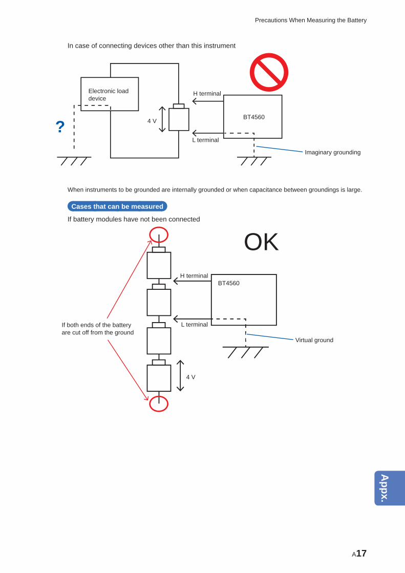
A17
Precautions When Measuring the Battery
In case of connecting devices other than this instrument
Imaginary grounding
4 V
H terminal
L terminal
BT4560
Electronic load device
?
When instruments to be grounded are internally grounded or when capacitance between groundings is large.
Cases that can be measured
If battery modules have not been connected
If both ends of the battery are cut off from the ground
Virtual ground
4 V
H terminal
L terminal
BT4560
OK
10
9
8
7
6
5
4
3
2
1
Appx.
Ind.
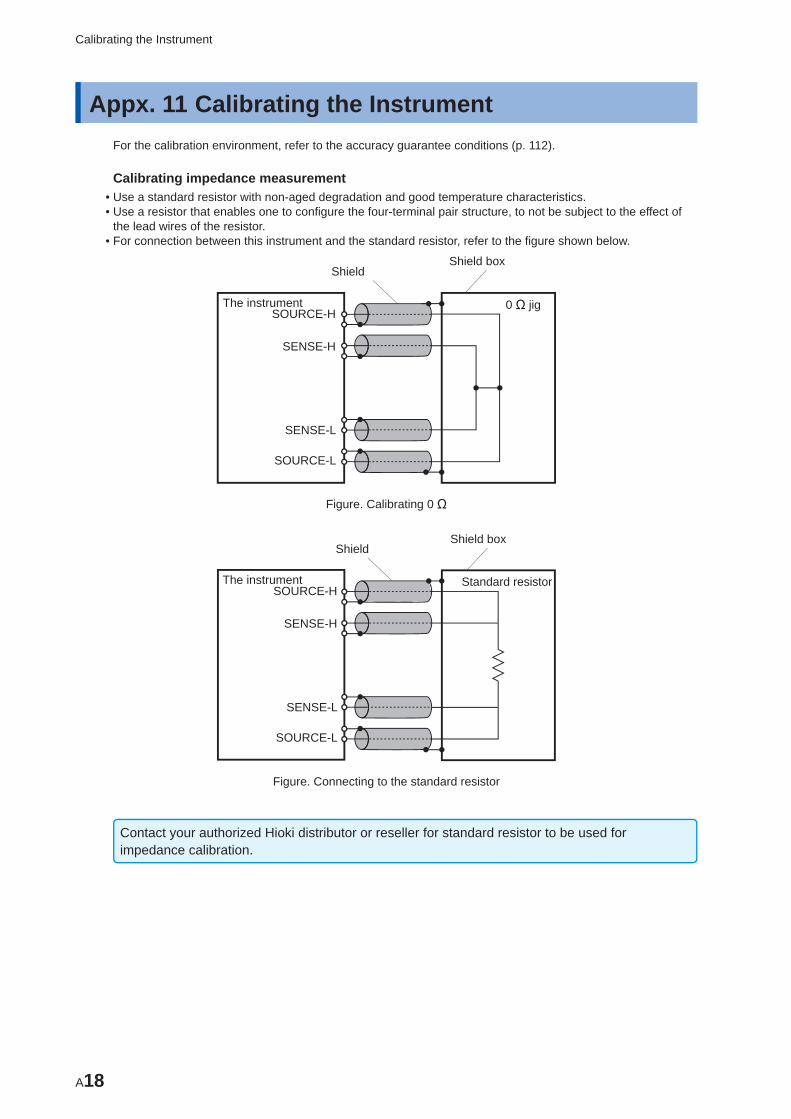
A18
Calibrating the Instrument
Appx. 11 Calibrating the Instrument For the calibration environment, refer to the accuracy guarantee conditions (p. 112).
Calibrating impedance measurement • Use a standard resistor with non-aged degradation and good temperature characteristics. • Use a resistor that enables one to confi gure the four-terminal pair structure, to not be subject to the effect of the lead wires of the resistor.
• For connection between this instrument and the standard resistor, refer to the fi gure shown below.
The instrument 0 Ω jigSOURCE-H
SENSE-H
SENSE-L
SOURCE-L
ShieldShield box
Figure. Calibrating 0 Ω
The instrument Standard resistorSOURCE-H
SENSE-H
SENSE-L
SOURCE-L
ShieldShield box
Figure. Connecting to the standard resistor
Contact your authorized Hioki distributor or reseller for standard resistor to be used for impedance calibration.
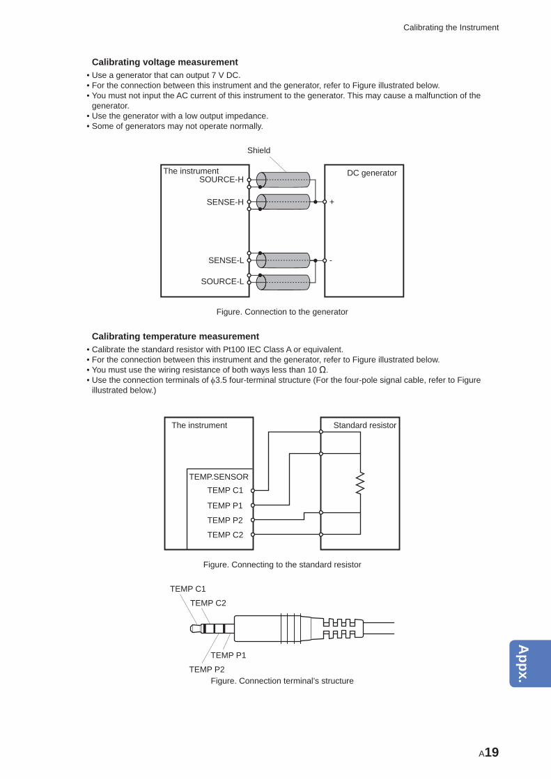
A19
Calibrating the Instrument
Calibrating voltage measurement • Use a generator that can output 7 V DC. • For the connection between this instrument and the generator, refer to Figure illustrated below. • You must not input the AC current of this instrument to the generator. This may cause a malfunction of the generator.
• Use the generator with a low output impedance. • Some of generators may not operate normally.
The instrument DC generatorSOURCE-H
SENSE-H
SENSE-L
SOURCE-L
Shield
+
-
Figure. Connection to the generator
Calibrating temperature measurement • Calibrate the standard resistor with Pt100 IEC Class A or equivalent. • For the connection between this instrument and the generator, refer to Figure illustrated below. • You must use the wiring resistance of both ways less than 10 Ω. • Use the connection terminals of 3.5 four-terminal structure (For the four-pole signal cable, refer to Figure illustrated below.)
Standard resistorThe instrument
TEMP.SENSORTEMP C1
TEMP C2
TEMP P1
TEMP P2
Figure. Connecting to the standard resistor
TEMP C1
TEMP C2
TEMP P1
TEMP P2Figure. Connection terminal’s structure
10
9
8
7
6
5
4
3
2
1
Appx.
Ind.
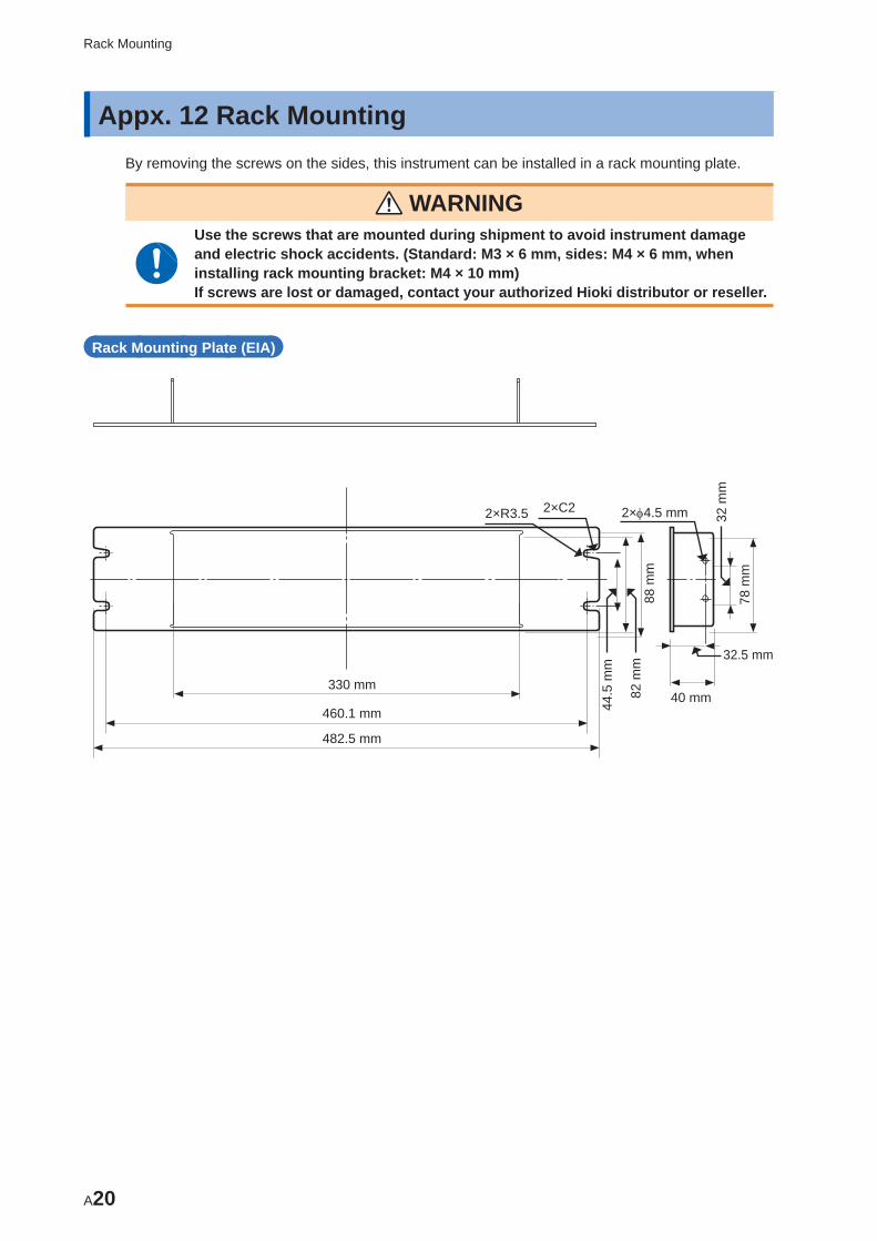
A20
Rack Mounting
Appx. 12 Rack MountingBy removing the screws on the sides, this instrument can be installed in a rack mounting plate.
WARNING Use the screws that are mounted during shipment to avoid instrument damage and electric shock accidents. (Standard: M3 × 6 mm, sides: M4 × 6 mm, when installing rack mounting bracket: M4 × 10 mm)If screws are lost or damaged, contact your authorized Hioki distributor or reseller.
Rack Mounting Plate (EIA)
330 mm
460.1 mm
482.5 mm
44.5
mm
82 m
m88
mm
32.5 mm
40 mm
78 m
m
32 m
m
2×4.5 mm2×C22×R3.5
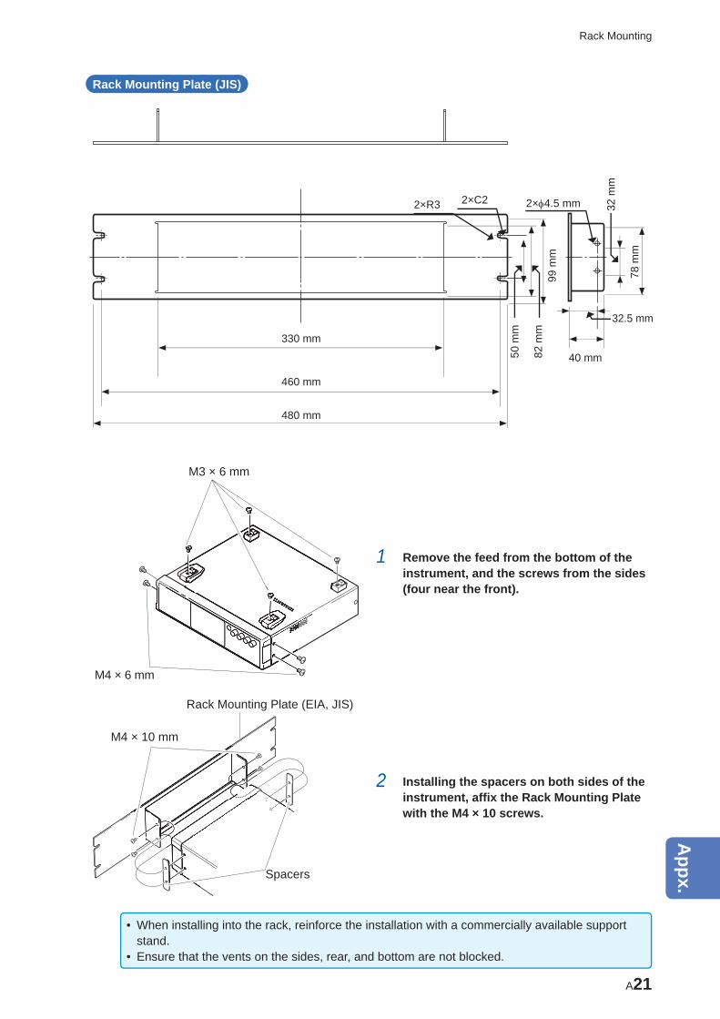
A21
Rack Mounting
Rack Mounting Plate (JIS)
330 mm
50 m
m
82 m
m99
mm
32.5 mm
40 mm
78 m
m
32 m
m
2×4.5 mm2×C22×R3
460 mm
480 mm
M3 × 6 mm
M4 × 6 mm
1 Remove the feed from the bottom of the instrument, and the screws from the sides (four near the front).
Rack Mounting Plate (EIA, JIS)
M4 × 10 mm
Spacers
2 Installing the spacers on both sides of the instrument, affi x the Rack Mounting Plate with the M4 × 10 screws.
• When installing into the rack, reinforce the installation with a commercially available support stand.
• Ensure that the vents on the sides, rear, and bottom are not blocked.
10
9
8
7
6
5
4
3
2
1
Appx.
Ind.
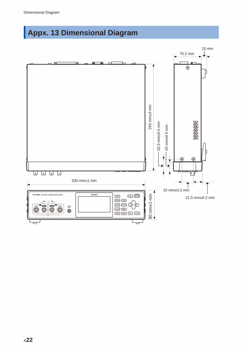
A22
Dimensional Diagram
Appx. 13 Dimensional Diagram
330 mm±1 mm
80 m
m±1
mm
293
mm
±3 m
m
25 m
m±0
.5 m
m
32.5
mm
±0.5
mm
32 mm±0.2 mm
21.5 mm±0.2 mm
75.2 mm15 mm
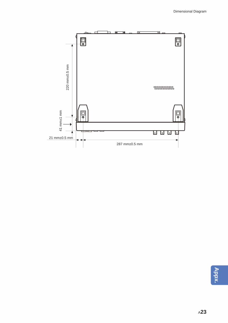
A23
Dimensional Diagram
287 mm±0.5 mm
220
mm
±0.5
mm
41 m
m±1
mm
21 mm±0.5 mm
10
9
8
7
6
5
4
3
2
1
Appx.
Ind.

A24
Dimensional Diagram
Index1
A
Absolute value .................................................... 49, 54Accessory/Accessories............................................ 116Accuracy .................................................................. 112Average function ....................................................... 42
B
Backlight ................................................................... 67Battery measurement
Precaution point .................................................. A15BT4560 ....................................................................... 1
C
Calibration .............................................................. A18Cleaning ................................................................. 123Command ......................................................... 95, 100Comparator function
OFF ....................................................................... 50ON ......................................................................... 50Confi rming the sound ............................................ 55Upper and lower limit value ................................... 51Judgment result..................................................... 56
ConnectFour-terminal cable ............................................... 18Temperature sensor .............................................. 18Power cord ............................................................ 17
ConnectionPerforming............................................................. 26Failure ................................................................... 26Setting ................................................................... 28Measurement abnormality detection ..................... 26
Contact error............................................................. 30Measurement current abnormality ........................ 30Measurement frequency ....................................... 30
Current sink (NPN) ................................................... 80Current source (PNP) ............................................... 80
D
Dimensional Diagram ............................................. A22Discarding............................................................... 124Display ...................................................................... 12
E
Eddy current ............................................................. A8Error display and Remedy ...................................... 121EXT I/O NPN/PNP switch ......................................... 12EXT I/O terminal ....................................................... 12EXT.I/O test functions ............................................... 94
F
Four-terminal pair method ........................................ A2
I
Impedance measurement (Z) ................................... 23Voltage measurement (V) ..................................... 23Measurement functions ......................................... 23
InitializingNORMAL ............................................................... 74SYSTEM ............................................................... 74
Initial testing table ..................................................... 76Input signal ......................................................... 82, 83Installation .................................................................. 7Internal circuitry ........................................................ 91
Connection examples............................................ 93Electrical specifi cations ......................................... 92
J
Judgment result ........................................................ 56
K
Key operating soundOFF ....................................................................... 65ON ......................................................................... 65
Key operationIneffective .............................................................. 63Effective ................................................................ 63
L
Lithium Battery........................................................ 124
M
Manufacturer’s serial number ................................... 12Measurement example ............................................. 21Measurement probe ............................................... A12
Extension .............................................................. A6Self-make .............................................................. A4
Measurement range ................................................. 33Measurement screen ................................................ 15Measurement Signal Zero Cross Stop Function....... 47Measurement speed ................................................. 24Measurement terminal .............................................. 12
O
Operating keys ................................................... 12, 14Operational expression............................................. A1Option .................................................................. 2, 116Output signal ............................................................ 83Overrange indication ................................................ 32
Index
10
9
8
7
6
5
4
3
2
1
Appx.
Index
Index2
Index
T
Temperature sensor terminal .................................... 12Test lead ................................................................... 22Timing chart .............................................................. 84Trigger function ......................................................... 37
Input external trigger ............................................. 37Setting ................................................................... 37
U
USB Interface ........................................................... 12Specifi cations ........................................................ 95Use ........................................................................ 96
V
Vent .......................................................................... 12Voltage limit function................................................. 45
Z
Zero adjustment........................................................ A8
P
Panel loading function .............................................. 60Panel saving function ............................................... 58Power cord ............................................................... 17Power inlet ................................................................ 12Power supply
Turn on .................................................................. 19Turn off .................................................................. 19
Power switch ............................................................ 12Pre-operation inspection........................................... 19Progress bar ............................................................. 25
Q
Q&A ......................................................................... 117
R
Rack mounting........................................................ A20replacement pars .................................................... 123Reset ........................................................................ 74RS-232C Interface .................................................... 12
Specifi cations ........................................................ 95Use ........................................................................ 98
S
Sample delay function .............................................. 38Screen confi guration................................................. 15Screen contrast ........................................................ 66Self-calibration function ............................................ 41Setting
Measurement speed ............................................. 23Zero adjustment .................................................... 22
Setting conditionsDeleting ................................................................. 61Saving ................................................................... 58Reading out ........................................................... 60
Setting screen........................................................... 15Slope Correction Function ........................................ 43Specifi cations ......................................................... 101Stand ........................................................................ 13Switching unit ......................................................... A13System test ............................................................... 68
I/O TEST ............................................................... 68KEY TEST ............................................................. 69LCD TEST ............................................................. 70ROM TEST ............................................................ 71
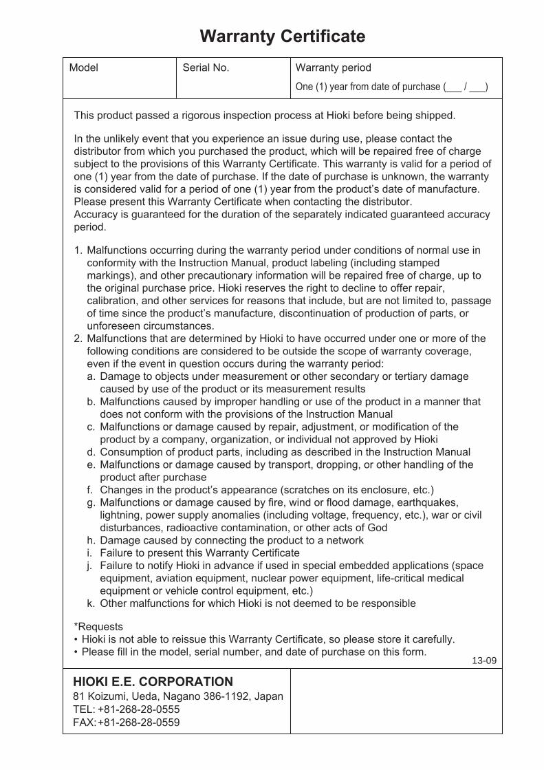
13-09