Embed Size (px)
Citation preview
BTL7-V50T-…
Configuration Manual
english

www.balluff.com
www.balluff.com 3english
BTL7-V50T-…Configuration Manual
1 Notes to the user 5
1.1 Symbols and conventions 51.2 Explanation of the warnings 51.3 Abbreviations 51.4 Registered trademarks 5
2 Device properties 5
3 PROFINET fundamentals 6
3.1 Functional principle 63.2 Object model 63.3 Protocol 73.4 Real time classes 7
3.4.1 Topologies and using switches 73.4.2 Performance 83.4.3 PROFINET state machine 8
4 Configuration 9
4.1 Basic configuration 94.1.1 (Sub)net mask 9
4.2 Device profile: Encoder Profile V4.1 Application Class 4 94.2.1 Standard data types according to IEC 61158-5:2003 94.2.2 Standard signals 10
4.3 Data telegrams 124.4 Setting the number of magnets 134.5 Diagnosis 134.6 Alarm mechanism 14
5 Parameter 15
5.1 Configuration options 155.2 Module access point parameters 15
5.2.1 Diagnostic time for FMM 155.2.2 Measuring direction 155.2.3 Encoder class 4 functionality 155.2.4 Scale control 155.2.5 Alarm channel control 165.2.6 Compatibility mode V3.1 165.2.7 Scaling: Measuring units per revolution 165.2.8 Scaling: Total measuring range 165.2.9 Tolerated number of sign-of-life errors 165.2.10 Speed unit 16
5.3 Parameters to affect measured value acquisition 165.4 970, 971: Loading and saving parameters 165.5 972: Drive reset 175.6 Parameters for automatic identification of the BTL7-V50T-… 17
5.6.1 964: Drive identification 175.6.2 965: Profile identification 175.6.3 974: Base mode parameter access service identification 175.6.4 975: Drive object identification 175.6.5 979: Sensor format 175.6.6 980: Number list of defined parameters 17
5.7 Parameters for addressing 175.8 Parameter for status display 175.9 2050: Temperature values 17
4 english
BTL7-V50T-…Configuration Manual
6 Switching from Profibus to PROFINET 18
7 Configuration 19
7.1 Installing the GSD file 197.2 Installing the transducer 19
7.2.1 Network data 207.3 Exchanging the device without a programming device and automatic
start-up 207.4 Assigning the device name 20
7.4.1 Sensor parameters 217.5 Configuring IRT mode 22
7.5.1 Determining the minimum possible processing time for the slave (Tinput) 22
7.5.2 Settings in PROFINET IO Domain Management 237.5.3 Setting the topology 247.5.4 Configuring the controller 257.5.5 Configuring the slave 26
8 Application program 27
8.1 Reading the position data 278.2 Reading and writing parameters 278.3 Example: Parameter access 28
9 Appendix 33

www.balluff.com 5english
1.1 Symbols and conventions
Instructions are indicated by a preceding triangle. The result of an action is indicated by an arrow.
► Instruction 1 ⇒ Action result
Action sequences are numbered consecutively:1. Instruction 12. Instruction 2
Buttons are written in small caps, e.g. Update transdUcer.
Menu commands are joined with a greater-than sign, e.g. “Settings > Options” stands for the menu command “Options” from the “Settings” menu.
Note, tipThis symbol indicates general notes.
1.2 Explanation of the warnings
Always observe the warnings in these instructions and the measures described to avoid hazards.
The warnings used here are structured as follows:
SIGNAL WORDHazard type and sourceConsequences if not complied with
► Measures to avoid hazards
The individual signal word means:
DANGERThe general warning symbol in conjunction with the signal word DANGER identifies a hazard which, if not avoided, will certainly result in death or serious injury.
1.3 Abbreviations
ASE Application service element
CBA Component-based automation
CC Conformance classes
DP Device profile
FMM Flexible Magnet Mode
GSD General station description
GSDML GSD markup language
IO device Field device (sensor, actuator)
IP Internet protocol
IRT Isochronous real time
LLDP Link Layer Discovery Protocol
MRP Media Redundancy Protocol
MRRT Media Redundancy Real-Time Protocol
PROFINET Process Field Network
RT Real time
1.4 Registered trademarks
Windows® is a registered trademark of the Microsoft Corporation.PROFINET and PROFIBUS are registered trademarks of PROFIBUS International, Karlsruhe, Germany.All other mentioned brands are the property of the respective rightful owner.
BTL7-V50T-… micropulse transducers are operated and configured in a PROFINET bus system.
For parameterization, see the parameter table on page 33.
Constant BTL parameters:– Manufacturer ID: 0x010000E8– Product ID: 0xDB01– Manufacturer name: Balluff GmbH– Device name: BTL7-V50T-…– Serial number: yymmdd000xxxxx ZZ
– yy/mm/dd: Production date (year/month/day)– xxxxx: Sub-series– ZZ: Country of origin
DE = GermanyHU = Hungary
1 Notes to the user
2 Device properties
BTL7-V50T-…Configuration Manual

6 english
PROFINET (PROcess FIeld NETwork) is an open industrial Ethernet standard, developed by Siemens and the member companies of the PROFIBUS user organization. PROFINET uses TCP/IP and IT standards, is real-time-Ethernet-capable, and permits the integration of fieldbus systems. PROFINET supplements the PROFIBUS technology for applications requiring fast data communication together with industrial IT functions.
PROFINET has a modular design. The major difference between the variants lies in the type of data exchange to meet speed requirements.
PROFINET offers two combinable variants PROFINET CBA and PROFINET IO.
PROFINET IO is the newer technology tailored to communication between a controller and a decentralized peripheral. It is based on the proven functional principle of Profibus-DP and uses Fast Ethernet technology as its transfer medium. Communication is performed in both real time (RT) and isochronous real time (IRT). Within PROFINET IO, process data and alarms are always transferred in real time. This communication is the basis for data exchange. Real-time data have priority over TCP(UDP)/IP data. As a result, bus cycle times of only a few milliseconds can be achieved.
Isochronous data exchange with PROFINET is defined in the isochronous real time concept. Here, the data exchange cycles range from a few hundred microseconds to up to one millisecond. The difference as compared with RT communication lies in the determinism so that the bus cycle can be maintained with maximum precision. The start of a bus cycle can deviate by no more than one microsecond.
PROFINET CBA (component-based automation) is the original variant and follows a distributed automation approach. It can be used by intelligent automation devices in a modular system structure to communicate. PROFINET CBA and PROFINET IO can communicate on the same bus system simultaneously. They can be operated separately or combined, so that a partial system with PROFINET IO appears in the system view as a PROFINET-CBA system.
3.1 Functional principle
PROFINET is based on the standard Ethernet protocol: Only full duplex with 100 Mbit/s, electrical (100BASE-TX) or optical (100BASE-FX) is permitted as device connection according to IEEE 802.3. Thus, no more collisions can take place in a PROFINET network. Auto-crossover is obligatory for all connections and the use of crossover cables is not necessary. From IEEE 802.1Q, VLAN with priority tagging is used. All real-time data is given top priority (6) and thus forwarded by a switch with only a minimal delay.
OSI layer PROFINET
7aApplication
IO services and protocols
CBA services and protocols
7b
Empty
RPCDCOM & RPC
Empty
6Presentation
– –5
Session
4Transport
UDP TCP
3Network
IP, ARP, SNMP, DHCP
2Data link
CSMA/CD, VLAN, DCP, MRP, MRRT, LLDP
1Bit transfer(physical)
100BASE-TX, 100BASE-FX
The PROFINET protocol can be mapped and displayed with every Ethernet analysis tool. The current version of Wireshark (for Windows, Linux, and OS X, available free-of-charge at www.wireshark.org) also decodes PROFINET telegrams.
The Media Redundancy Protocol (MRP) allows for the setup of a redundant, protocol-independent ring topology with a switching time under 50 ms. For redundant ring switches without time delay in the case of an error, the Media Redundancy Real-Time Protocol (MRRT) must be used.
The Link Layer Discovery Protocol (LLDP) has been supplemented with additional parameters so that not only neighbor detection, but also signal runtime on the connection lines can be communicated.
3.2 Object model
The basic model which PROFIdrive is based on consists of three device classes:– The controller (PLC) is joined to one or more drives
(axes) and controls the entire system.– Peripheral devices (P devices), such as the
BTL7-V50T-... transducer, are joined to at least one controller that monitors or controls them.
– The supervisor is generally a computer with configuration software which can be used to set parameters and monitor the peripheral devices.
Each station on the bus consists of one network interface and one or more devices. The network interface connects the station to the network. To uniquely identify a PROFINET device, the network, the station, and the device must be specified. A PROFINET device consists of one or more functional objects. The BTL7-V50T-… transducer is a homogenous peripheral device (P device) with an encoder unit. By pooling multiple drive objects into drive units, the associations of the drive objects with a physical unit can be mapped.
3 PROFINET fundamentals
BTL7-V50T-…Configuration Manual
www.balluff.com 7english
In addition, the communication object that establishes a relationship between the network interface and the drive object is defined. The communication object is a communication endpoint that can be addressed by the system, as well as connected to a functional object.
3.3 Protocol
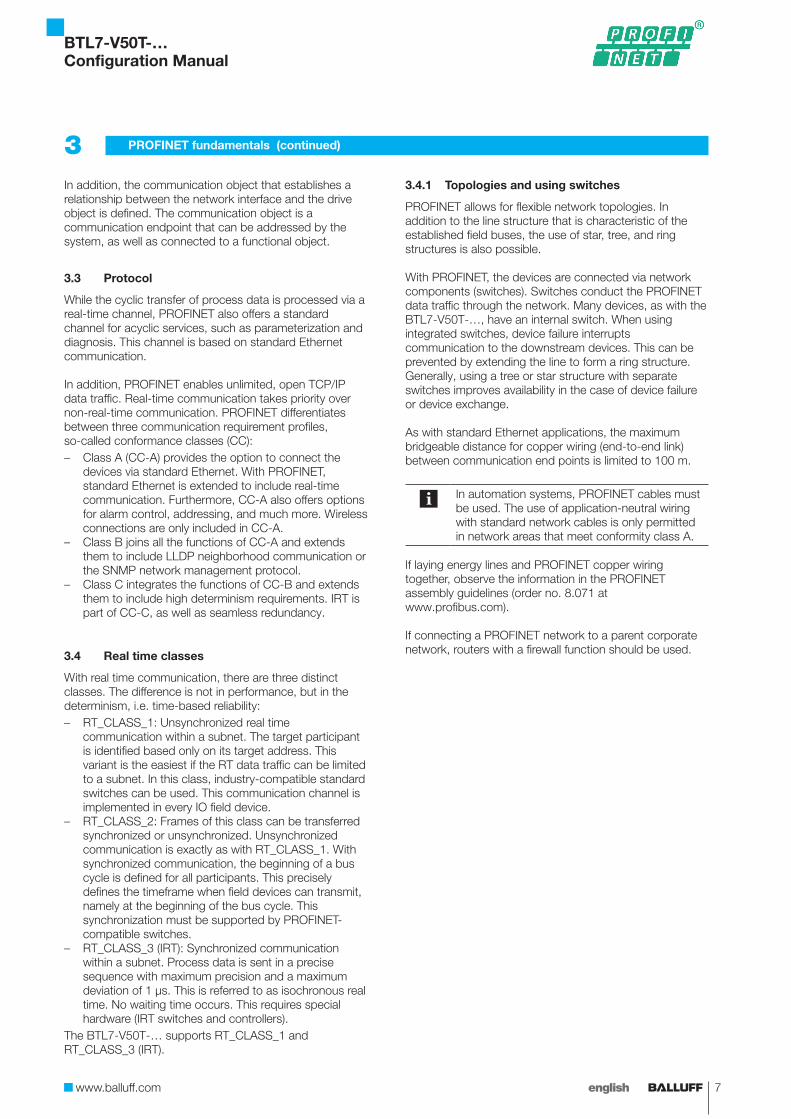
While the cyclic transfer of process data is processed via a real-time channel, PROFINET also offers a standard channel for acyclic services, such as parameterization and diagnosis. This channel is based on standard Ethernet communication.
In addition, PROFINET enables unlimited, open TCP/IP data traffic. Real-time communication takes priority over non-real-time communication. PROFINET differentiates between three communication requirement profiles, so-called conformance classes (CC):– Class A (CC-A) provides the option to connect the
devices via standard Ethernet. With PROFINET, standard Ethernet is extended to include real-time communication. Furthermore, CC-A also offers options for alarm control, addressing, and much more. Wireless connections are only included in CC-A.
– Class B joins all the functions of CC-A and extends them to include LLDP neighborhood communication or the SNMP network management protocol.
– Class C integrates the functions of CC-B and extends them to include high determinism requirements. IRT is part of CC-C, as well as seamless redundancy.
3.4 Real time classes
With real time communication, there are three distinct classes. The difference is not in performance, but in the determinism, i.e. time-based reliability:– RT_CLASS_1: Unsynchronized real time
communication within a subnet. The target participant is identified based only on its target address. This variant is the easiest if the RT data traffic can be limited to a subnet. In this class, industry-compatible standard switches can be used. This communication channel is implemented in every IO field device.
– RT_CLASS_2: Frames of this class can be transferred synchronized or unsynchronized. Unsynchronized communication is exactly as with RT_CLASS_1. With synchronized communication, the beginning of a bus cycle is defined for all participants. This precisely defines the timeframe when field devices can transmit, namely at the beginning of the bus cycle. This synchronization must be supported by PROFINET-compatible switches.
– RT_CLASS_3 (IRT): Synchronized communication within a subnet. Process data is sent in a precise sequence with maximum precision and a maximum deviation of 1 μs. This is referred to as isochronous real time. No waiting time occurs. This requires special hardware (IRT switches and controllers).
The BTL7-V50T-… supports RT_CLASS_1 and RT_CLASS_3 (IRT).
3.4.1 Topologies and using switches
PROFINET allows for flexible network topologies. In addition to the line structure that is characteristic of the established field buses, the use of star, tree, and ring structures is also possible.
With PROFINET, the devices are connected via network components (switches). Switches conduct the PROFINET data traffic through the network. Many devices, as with the BTL7-V50T-…, have an internal switch. When using integrated switches, device failure interrupts communication to the downstream devices. This can be prevented by extending the line to form a ring structure. Generally, using a tree or star structure with separate switches improves availability in the case of device failure or device exchange.
As with standard Ethernet applications, the maximum bridgeable distance for copper wiring (end-to-end link) between communication end points is limited to 100 m.
In automation systems, PROFINET cables must be used. The use of application-neutral wiring with standard network cables is only permitted in network areas that meet conformity class A.
If laying energy lines and PROFINET copper wiring together, observe the information in the PROFINET assembly guidelines (order no. 8.071 at www.profibus.com).
If connecting a PROFINET network to a parent corporate network, routers with a firewall function should be used.
3 PROFINET fundamentals (continued)
BTL7-V50T-…Configuration Manual

8 english
3.4.2 Performance
With PROFINET, up to 256 devices can be connected to one controller. This is twice as much as with PROFIBUS. The number of devices per PROFINET network is virtually unlimited. The only limitation is the availability of free IP addresses. The bandwidth in the PROFINET network is distributed intelligently by using switches and field devices with multiple ports.
3.4.3 PROFINET state machine
The BTL7-V50T-… operating modes behave corresponding to the PROFIdrive profile. Five states are implemented:
– Normal operation: The sensor operates normally. Setting bit 13 in G1_STW requests the output of the position value in G1_XIST2 (for G1_STW and G1_XIST2 see also 4.2.2 Standard signals).
– Parking: The transducer outputs position data, but does not send alarms or warnings. Existing alarms and warnings are deleted. This state can be set by setting bit 14 in G1_STW.
– Error: This state is set if there is an error in the measuring system. An error code is output in G1_XIST2 and bit 15 is set in G1_ZSW. The error must be acknowledged by setting bit 15 in G1_STW.
3 PROFINET fundamentals (continued)
– Error acknowledgment: In this state, errors are acknowledged. Setting bit 15 initiates the acknowledgment; the positive edge is the deciding signal. If the cause for the error is eliminated, the error is deleted and the sensor changes to the state Normal Operation. If the cause for the error still exists, the sensor returns to the Error state after resetting bit 15 of G1_STW. Upon successful acknowledgment, bit 15 in G1_ZSW1 is deleted along with the error code in G1_XIST2.
– Set/shift home position: Setting bit 11/12 in G1_STW in the Normal Operation state can achieve this state. Bit 11 determines whether a preset or offset is to be set. A positive edge at bit 12 switches to the state and sets the preset/offset.
Fig. 3-1: PROFINET state machine
BTL7-V50T-…Configuration Manual
www.balluff.com 9english
Configuration is based on the general station description (GSD) file, which can be downloaded from the Balluff homepage (www.balluff.com). It is installed in the configuration program as per the specifications of the controller manufacturer.
4.1 Basic configuration
All PROFINET devices require an IP address for operation on Ethernet. To facilitate configuration, the user is usually prompted to assign an IP address to the controller once. While configuring the PROFINET-IO controller in the hardware configuration program, a dialog for IP address and subnet mask selection appears. The device IP addresses are usually assigned automatically by the controller.
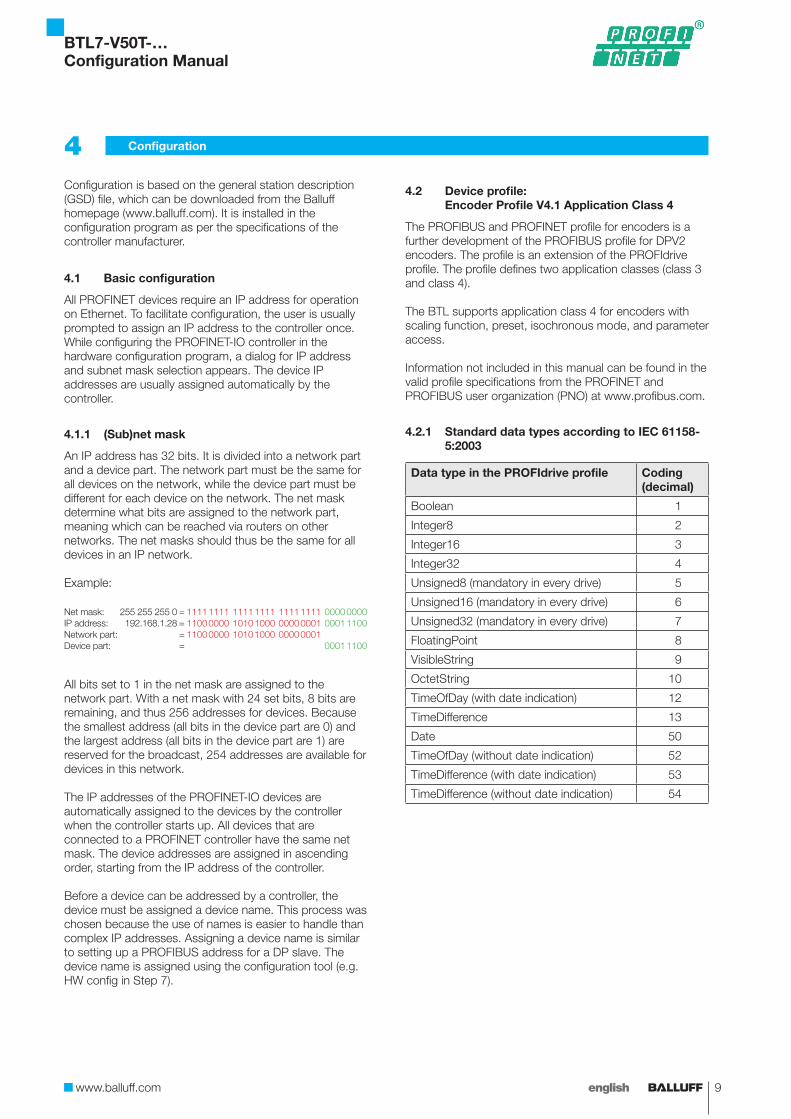
4.1.1 (Sub)net mask
An IP address has 32 bits. It is divided into a network part and a device part. The network part must be the same for all devices on the network, while the device part must be different for each device on the network. The net mask determine what bits are assigned to the network part, meaning which can be reached via routers on other networks. The net masks should thus be the same for all devices in an IP network.
Example:
Net mask: 255 255 255 0 = 1111 1111 1111 1111 1111 1111 0000 0000IP address: 192.168.1.28 = 1100 0000 1010 1000 0000 0001 0001 1100Network part: = 1100 0000 1010 1000 0000 0001Device part: = 0001 1100
All bits set to 1 in the net mask are assigned to the network part. With a net mask with 24 set bits, 8 bits are remaining, and thus 256 addresses for devices. Because the smallest address (all bits in the device part are 0) and the largest address (all bits in the device part are 1) are reserved for the broadcast, 254 addresses are available for devices in this network.
The IP addresses of the PROFINET-IO devices are automatically assigned to the devices by the controller when the controller starts up. All devices that are connected to a PROFINET controller have the same net mask. The device addresses are assigned in ascending order, starting from the IP address of the controller.
Before a device can be addressed by a controller, the device must be assigned a device name. This process was chosen because the use of names is easier to handle than complex IP addresses. Assigning a device name is similar to setting up a PROFIBUS address for a DP slave. The device name is assigned using the configuration tool (e.g. HW config in Step 7).
4.2 Device profile: Encoder Profile V4.1 Application Class 4
The PROFIBUS and PROFINET profile for encoders is a further development of the PROFIBUS profile for DPV2 encoders. The profile is an extension of the PROFIdrive profile. The profile defines two application classes (class 3 and class 4).
The BTL supports application class 4 for encoders with scaling function, preset, isochronous mode, and parameter access.
Information not included in this manual can be found in the valid profile specifications from the PROFINET and PROFIBUS user organization (PNO) at www.profibus.com.
4.2.1 Standard data types according to IEC 61158-5:2003
Data type in the PROFIdrive profile Coding (decimal)
Boolean 1
Integer8 2
Integer16 3
Integer32 4
Unsigned8 (mandatory in every drive) 5
Unsigned16 (mandatory in every drive) 6
Unsigned32 (mandatory in every drive) 7
FloatingPoint 8
VisibleString 9
OctetString 10
TimeOfDay (with date indication) 12
TimeDifference 13
Date 50
TimeOfDay (without date indication) 52
TimeDifference (with date indication) 53
TimeDifference (without date indication) 54
4 Configuration
BTL7-V50T-…Configuration Manual

10 english
4.2.2 Standard signals
The position interface defined in the profile is a standardized connection between the sensor and the controller. Some defined standard signals serve for I/O data configuration. The signal numbers come from the PROFIdrive profile.
Signal no.
Description Abbreviation Length (bit)
9 Sensor 1 control word G1_STW 16
10 Sensor 1 status word G1_ZSW 16
11 Sensor 1 current position value 1
G1_XIST1 32
12 Sensor 1 current position value 2
G1_XIST2 32
80 Encoder control word 2 STW2_ENC 16
81 Encoder status word 2 ZSW2_ENC 16
G1_STW – sensor control word
The sensor control word controls the most important encoder functions. Bits 0 to 10 are reserved.
Bit 11 (Home position mode) and bit 12 (Request set/shift of home position)Bits 11 (Home position mode) and 12 (Request set/shift of home position) control the offset. They are edge-triggered signals to control the internal offset calculation. This means that only their status change triggers an action. In case of a pending error, the offset cannot be set.
If bit 12 is set to “Low,” the offset calculation is in normal mode. The offset calculation is not changed, regardless of the status of bit 11.If bit 12 switches from low to high while bit 11 is set to low, the offset is changed into absolute mode. The preset value from parameter 2000 is taken from the encoder profile and an offset value is calculated so that the current position added to the offset value results in the preset value.
Offset value = preset value – parameter 2000Output position = position value + offset value
Parameter 2000
Offset valueActual value
Home position mode (bit 11) = 0Request of home position (bit 12) = 1
4 Configuration (continued)
If bit 11 and bit 12 switch to high at the same time, the offset is set to relative mode. In this case, the preset value from parameter 2000 is interpreted as the offset value and added to the position value.
Parameter 2000
Offset valueActual value
Home position mode (bit 11) = 1Request of home position (bit 12) = 1
Bit 13 (Request absolute value cyclically)This bit requests the additional transfer of the position value (actual value) in G1_XIST2. If this bit is deleted, an invalid value is transferred in accordance with specifications, in our case the error value (0x7FFFFFFF). In the case of an error, G1_XIST2 always contains the error code, regardless of whether the bit is set or not.
Bit 14 (Activate parking sensor)In the parked state, the encoder remains on the bus with an active sign of life. Position data is output. The encoder error and diagnosis are switched off. No error reports are transferred via diagnosis. Existing alarms and warnings are deleted. Setting this bit switches the sensor into this state.
Bit 15 (Acknowledge a sensor error)Setting this bit acknowledges and resets a sensor error. The acknowledgment has no effect if the cause for the error persists.
BTL7-V50T-…Configuration Manual
www.balluff.com 11english
G1_ZSW - Sensor status word
The sensor status word signalizes the state of the encoder and reflects the result of the settings in the G1_STW sensor control word.
Bit 11: Requirement of error acknowledgment detectedThis bit indicates that the acknowledgment of a sensor error is in progress. It is set if resetting an error after acknowledgement takes longer than one bus cycle.
Bit 12: Set/shift of home position executedIndicates that an offset has been set.
Bit 13: Transmit absolute value cyclicallyThis bit is independent of bit 13 in G1_STW and indicates that the encoder is transmitting the absolute value of magnet 1 in G1_XIST2. Bit 13 cannot be set simultaneously with bit 15.
Bit 14: Parking sensor activeIndicates that the encoder is parked and therefore not transmitting error messages.
Bit 15 Sensor errorIndicates a sensor error. The error code is output in G1_XIST2. Bit 13 and bit 15 cannot be set simultaneously. Bit 13 indicates the transfer of a valid position value in G1_XIST2, bit 15 signalizes that the error code is being transmitted in G1_XIST2.
ZSW2 status word 2
Bit 10: Control by PLCSo that the entries in G1_STW are taken into consideration, the bit must be set to 1. If the bit is set to 0, all entries in G1_STW are ignored.If "compatibility mode V3.1" is activated, this function is deactivated, meaning the entries in G1_STW are always taken into consideration.
Bit 12-15: Slave sign of lifeIn the second status word, bits 12 to 15 are used as slave signs of life. This is a four-bit counter. After successful synchronization, it begins with a value between 0 and 15. In each cycle, the counter is incremented by the slave; the value range spanning from 1 to 15. A value of 0 indicates an error.
4 Configuration (continued)
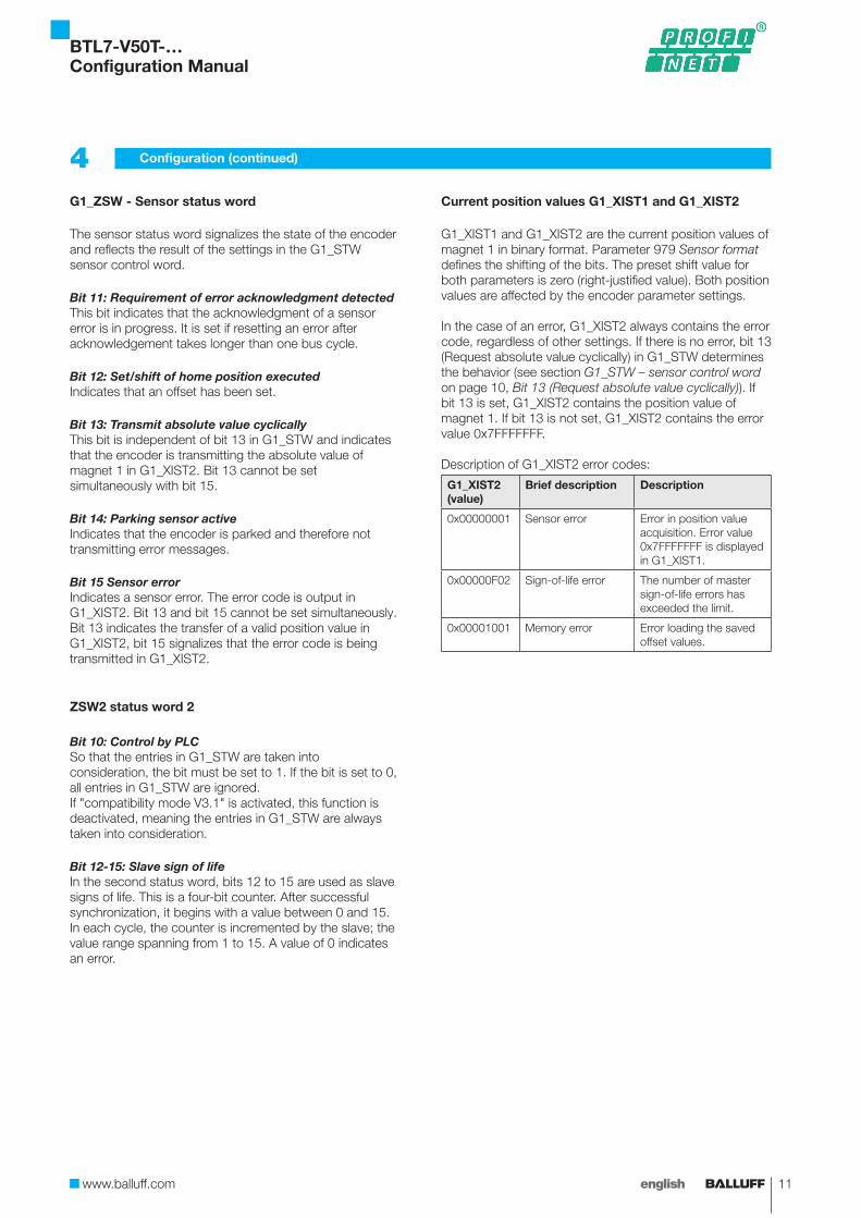
Current position values G1_XIST1 and G1_XIST2
G1_XIST1 and G1_XIST2 are the current position values of magnet 1 in binary format. Parameter 979 Sensor format defines the shifting of the bits. The preset shift value for both parameters is zero (right-justified value). Both position values are affected by the encoder parameter settings.
In the case of an error, G1_XIST2 always contains the error code, regardless of other settings. If there is no error, bit 13 (Request absolute value cyclically) in G1_STW determines the behavior (see section G1_STW – sensor control word on page 10, Bit 13 (Request absolute value cyclically)). If bit 13 is set, G1_XIST2 contains the position value of magnet 1. If bit 13 is not set, G1_XIST2 contains the error value 0x7FFFFFFF.
Description of G1_XIST2 error codes:
G1_XIST2 (value)
Brief description Description
0x00000001 Sensor error Error in position value acquisition. Error value 0x7FFFFFFF is displayed in G1_XIST1.
0x00000F02 Sign-of-life error The number of master sign-of-life errors has exceeded the limit.
0x00001001 Memory error Error loading the saved offset values.
BTL7-V50T-…Configuration Manual
12 english
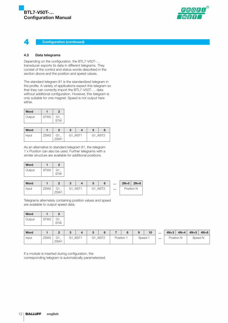
4.3 Data telegrams
Depending on the configuration, the BTL7-V50T-… transducer exports its data in different telegrams. They consist of the control and status words described in the section above and the position and speed values.
The standard telegram 81 is the standardized telegram in the profile. A variety of applications expect this telegram so that they can correctly import the BTL7-V50T-… data without additional configuration. However, this telegram is only suitable for one magnet. Speed is not output here either.
Word 1 2
Output STW2 G1_STW
Word 1 2 3 4 5 6
Input ZSW2 G1_ZSW1
G1_XIST1 G1_XIST2
As an alternative to standard telegram 81, the telegram 1 x Position can also be used. Further telegrams with a similar structure are available for additional positions.
Word 1 2
Output STW2 G1_STW
Word 1 2 3 4 5 6 … 2N+5 2N+6
Input ZSW2 G1_ZSW1
G1_XIST1 G1_XIST2 … Position N
Telegrams alternately containing position values and speed are available to output speed data.
Word 1 2
Output STW2 G1_STW
Word 1 2 3 4 5 6 7 8 9 10 … 4N+3 4N+4 4N+5 4N+6
Input ZSW2 G1_ZSW1
G1_XIST1 G1_XIST2 Position 1 Speed 1 … Position N Speed N
If a module is inserted during configuration, the corresponding telegram is automatically parameterized.
4 Configuration (continued)
BTL7-V50T-…Configuration Manual
www.balluff.com 13english
4.4 Setting the number of magnets
BTL7-V50T-… can evaluate up to 16 magnets. In normal mode, it is recommended to set a fixed number of magnets in the configuration program by inserting a module, as this reduces susceptibility to malfunctions, as well as the processing speed. In flexible magnet mode (FMM), the number of magnets is variable.For magnets that are not detected or parameterized, the error value 0x7FFFFFFF is output as position and speed. If more magnets than parameterized are located in the measuring range (with FMM, more than 16), the excess magnets are ignored. BTL7-V50T-… always evaluates the magnets from the plug side regardless of other settings.
Flexible magnet mode (FMM)In flexible magnet mode, the number of magnets is not specified. The BTL7-V50T-... accepts any number of magnets up to a maximum of 16 and the changing of the number in operation as well. However, after the number of magnets is changed, a diagnosis is signaled, which can be cancelled after a period of time that can be configured in the Diagnostic time for FMM parameter. The new number of magnets is accepted once this period has elapsed. If no magnet is located in the detection range, the error remains until at least one magnet is detected. If no magnets are present, the error value 0x7FFFFFFF is output as position and speed value.
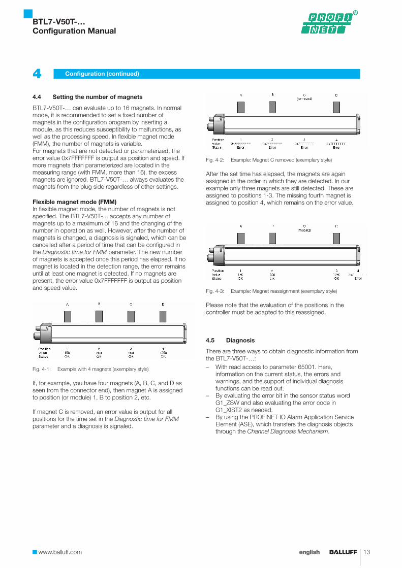
Fig. 4-1: Example with 4 magnets (exemplary style)
If, for example, you have four magnets (A, B, C, and D as seen from the connector end), then magnet A is assigned to position (or module) 1, B to position 2, etc.
If magnet C is removed, an error value is output for all positions for the time set in the Diagnostic time for FMM parameter and a diagnosis is signaled.
Fig. 4-2: Example: Magnet C removed (exemplary style)
After the set time has elapsed, the magnets are again assigned in the order in which they are detected. In our example only three magnets are still detected. These are assigned to positions 1-3. The missing fourth magnet is assigned to position 4, which remains on the error value.
Fig. 4-3: Example: Magnet reassignment (exemplary style)
Please note that the evaluation of the positions in the controller must be adapted to this reassigned.
4.5 Diagnosis
There are three ways to obtain diagnostic information from the BTL7-V50T-…:– With read access to parameter 65001. Here,
information on the current status, the errors and warnings, and the support of individual diagnosis functions can be read out.
– By evaluating the error bit in the sensor status word G1_ZSW and also evaluating the error code in G1_XIST2 as needed.
– By using the PROFINET IO Alarm Application Service Element (ASE), which transfers the diagnosis objects through the Channel Diagnosis Mechanism.
4 Configuration (continued)
BTL7-V50T-…Configuration Manual
14 english
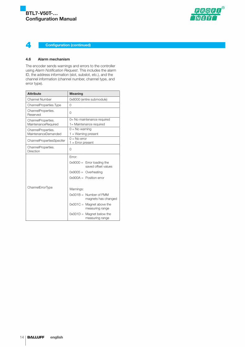
4.6 Alarm mechanism
The encoder sends warnings and errors to the controller using Alarm Notification Request. This includes the alarm ID, the address information (slot, subslot, etc.), and the channel information (channel number, channel type, and error type).
Attribute Meaning
Channel Number 0x8000 (entire submodule)
ChannelProperties.Type 0
ChannelProperties.Reserved
0
ChannelProperties.MaintenanceRequired
0= No maintenance required1= Maintenance required
ChannelProperties.MaintenanceDemanded
0 = No warning1 = Warning present
ChannelPropertiesSpecifer 0 = No error1 = Error present
ChannelProperties.Direction
0
ChannelErrorType
Error:
0x9000 = Error loading the saved offset values
0x9005 = Overheating
0x900A = Position error
Warnings:
0x001B = Number of FMM magnets has changed
0x001C = Magnet above the measuring range
0x001D = Magnet below the measuring range
4 Configuration (continued)
BTL7-V50T-…Configuration Manual
www.balluff.com 15english
5.1 Configuration options
The BTL7-V50T-… can be configured in two ways: Using the configuration tool, e.g. HW config in Step 7, parameters can be set that are stored in the GSD (general station description). They are then transmitted to the sensor during the start phase. This takes place during every start-up. As a result, after a device exchange the successor is automatically parameterized correspondingly.While it is running, the PLC program can access the parameters in the transducer’s object directory acyclically. The setup options for the object directory deviate from those of the module access point.
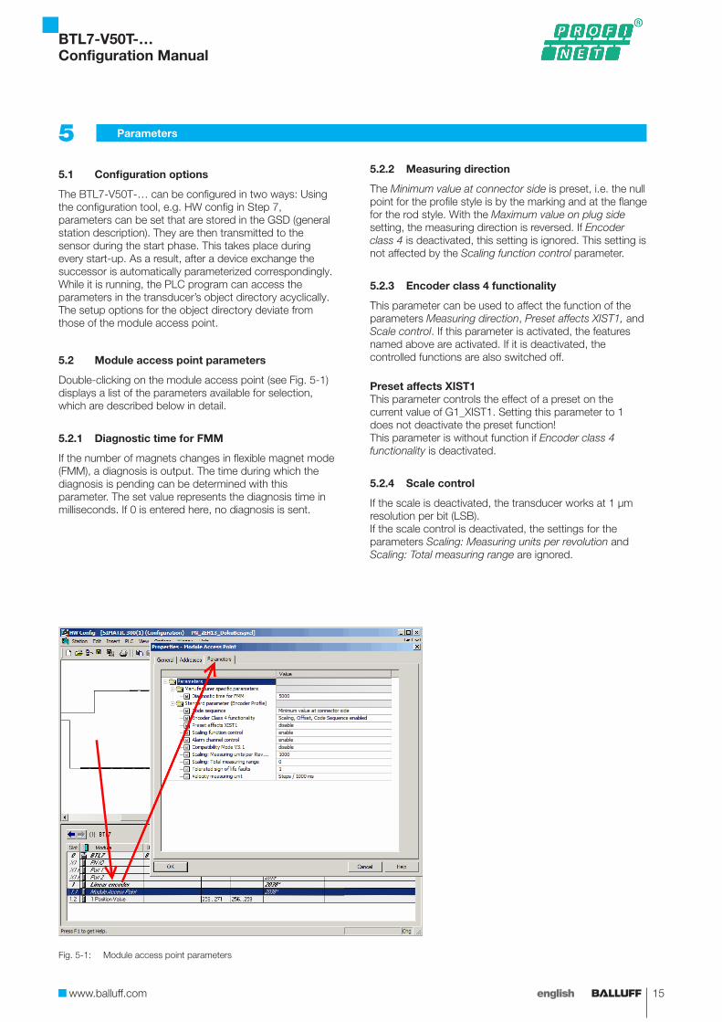
5.2 Module access point parameters
Double-clicking on the module access point (see Fig. 5-1) displays a list of the parameters available for selection, which are described below in detail.
5.2.1 Diagnostic time for FMM
If the number of magnets changes in flexible magnet mode (FMM), a diagnosis is output. The time during which the diagnosis is pending can be determined with this parameter. The set value represents the diagnosis time in milliseconds. If 0 is entered here, no diagnosis is sent.
5.2.2 Measuring direction
The Minimum value at connector side is preset, i.e. the null point for the profile style is by the marking and at the flange for the rod style. With the Maximum value on plug side setting, the measuring direction is reversed. If Encoder class 4 is deactivated, this setting is ignored. This setting is not affected by the Scaling function control parameter.
5.2.3 Encoder class 4 functionality
This parameter can be used to affect the function of the parameters Measuring direction, Preset affects XIST1, and Scale control. If this parameter is activated, the features named above are activated. If it is deactivated, the controlled functions are also switched off.
Preset affects XIST1This parameter controls the effect of a preset on the current value of G1_XIST1. Setting this parameter to 1 does not deactivate the preset function!This parameter is without function if Encoder class 4 functionality is deactivated.
5.2.4 Scale control
If the scale is deactivated, the transducer works at 1 μm resolution per bit (LSB).If the scale control is deactivated, the settings for the parameters Scaling: Measuring units per revolution and Scaling: Total measuring range are ignored.
5 Parameters
Fig. 5-1: Module access point parameters
BTL7-V50T-…Configuration Manual
16 english
5 Parameters (continued)
5.2.5 Alarm channel control
This parameter can be used to activate or deactivate the transfer of the encoder-specific alarm channel as a channel-related diagnosis. This reduces the amount of data transferred in isochronous mode.This parameter is only supported in compatibility mode V3.1!If the value is set to zero (presetting), only the communication-related alarms are transmitted via the alarm channel. If the value is one, the specific errors and warnings are also transferred via the alarm channel according to the encoder profile and profile definition.
5.2.6 Compatibility mode V3.1
Resetting this parameter establishes compatibility to version 3.1 of the PROFIdrive profile. The details can be seen in the following table:
Function Compatibility mode enable (=0), compatible to encoder profile V3.1
Compatibility mode disable (=1), no backwards compatibility (presetting)
Controlled by PLC (STW2_ENC)
Ignored; the control word G1_STW and the set values are always valid.Control requests (ZSW2_ENC) are not supported and are set to zero.
Supported
Maximum Master Sign-Of-Life failures parameter
Supported Not supported. A sign-of-life counter error is tolerated. Parameter 925 is optional for sign-of-life monitoring control.
Alarm channel control parameter
Supported Not supported; the application alarm channel is active and is controlled by a PROFIdrive parameter.
P965 – Profile version
31 (V3.1) 41 (V4.1)
5.2.7 Scaling: Measuring units per revolution
This parameter sets how many nanometers a measuring unit should contain. The smallest sensible unit and default value is 1000 nm, that is 1 µm. Smaller resolutions can lead to rounding effects. Thus, the unit should be chosen sensibly.The step interval can also be affected by the parameter Scaling: Total measuring range.The setting is only taken into consideration if Class 4 functionality and Scaling function are switched on. The data format is UNSIGNED32 (1 to 4294967295). The default value is 1000.
5.2.8 Scaling: Total measuring range
In this parameter, the number of steps into which the nominal length is to be divided can be indicated. The BTL7-V50T-... uses this to calculate the required step length. Step lengths under 1 µm are smaller than the measurement resolution and thus do not make sense.
Resolution (step length) =Nominal length
Measuring range in measuring units
If both Scaling: Measuring units per revolution and Scaling: Total measuring range are set, Scaling: Total measuring range has the higher priority.
5.2.9 Tolerated number of sign-of-life errors
If the sign-of-life monitoring is activated in the controller, a counter is incremented after each telegram. This allows the BTL7-V50T-... to recognize whether it has missed a telegram. This parameter sets the number of errors from which the device sends a sign-of-life error in G1_XIST2.
5.2.10 Speed unit
The speed can be selected from steps/1000 ms, steps/100 ms, and steps/10 ms. The step length is defined by the parameter Scaling: Measuring units per revolution or Scaling: Entire measurement range.
5.3 Parameters to affect measured value acquisition
Parameters 2000 to 2015 can be used to set the offsets and presets for magnets 1 to 16. The values are set in the unit parameterized during start-up.In parameter 65000, the preset value can be loaded that is used while setting the offset via G1_STW (see section G1_STW – sensor control word on page 10). This value only affects the first magnet and is identical to parameter 2000.
5.4 970, 971: Loading and saving parameters
With these parameters, the local parameter settings can be saved permanently or reset. Writing a 1 in parameter 970 resets all parameters to their delivery settings. If a 1 is written in parameter 971, the current parameter settings are saved permanently. The process is completed when the parameter is set back to 0 by the transducer.
BTL7-V50T-…Configuration Manual
www.balluff.com 17english
5 Parameters (continued)
5.5 972: Drive reset
DANGERUncontrolled system movementIf a drive reset is performed, the transducer is restarted immediately and aborts its function! The system may enter an uncontrolled state. This could result in personal injury and equipment damage.
► Only perform a drive reset if no persons or materials are in the system’s hazardous zones.
► Take the same safety precautions as for start-up! ► Observe the safety instructions of the equipment or
system manufacturer.
If a 1 is entered in this parameter, an instant reset is performed. The transducer is restarted immediately, like interrupting the power supply. The transducer aborts its function immediately! This also affects the internal switch that connects the two PROFINET interfaces. Devices downstream of the bus are also separated from the bus and thus the controller immediately. As a result, the system may enter an uncontrolled state.
5.6 Parameters for automatic identification of the BTL7-V50T-…
The parameters 964, 965, and 974 to 980 contain information that primarily serves for automatic identification of the transducer, e.g. upon connection to a positioning system. The information mapped here is of no interest to users.
5.6.1 964: Drive identification
This parameter contains information on the manufacturer, type of transducer, versions, and the number of drive objects.
5.6.2 965: Profile identification
This string contains the ID for PROFIdrive (61) and the version (41 for 4.1).
5.6.3 974: Base mode parameter access service identification
The information in this parameter aids the controller in setting up communication with the BTL7-V50T-.... This parameter is irrelevant for users.
5.6.4 975: Drive object identification
This parameter contains version information, manufacturer ID, as well as information on the drive object classes, and serves for automatic identification of the BTL7-V50T-....
5.6.5 979: Sensor format
This parameter also primarily serves for automatic identification of the BTL7-V50T-…. It defines the most important settings for the sensor and enables interpretation of G1_XIST1 and G1_XIST2.
5.6.6 980: Number list of defined parameters
This array is a list of the numbers of all parameters. Different tools and devices read out this information to determine which parameters the BTL7-V50T-… supports.
5.7 Parameters for addressing
Parameters 61000 to 61004 reflect the network settings, such as IP address or the station name that were made with the configuration tool. These parameters are read-only.
5.8 Parameter for status display
Parameter 65001 indicates the current operating status with errors and warnings.
5.9 2050: Temperature values
The temperature sensor is located inside the sensor on the circuit board and thus measures the temperature of the electronics that create heat. Thus, the temperature displayed in ongoing operation is normally higher than the ambient temperature. The values measured serve to assess the general thermal conditions and are not suitable for monitoring process temperatures and the like. The temperature is displayed in °C.
BTL7-V50T-…Configuration Manual
18 english
Often, the system and standard functions for Profibus previously used in Siemens CPUs are not suitable for PROFINET. However, there are often new functions whose use is similar to that of those for Profibus. These new functions are primarily suitable for both systems, so they can cover both PROFINET and Profibus functionalities at the same time.
The document Von_PROFIBUS_DP_nach_PROFINET_IO_en-US.pdf describes details and can be downloaded from the Siemens homepage at: http://support.automation.siemens.com
In case of access by means of SFB52 RDREC or SFB53 WRREC, some arguments must be included. Initially, the user requires the ID, the starting address of the E address space of the encoder. The user can determine this by left-clicking the device in the hardware configuration, right-clicking the module, and then selecting Object properties. The Addresses tab contains the key figures.
The Index parameter specifies the data set number. Since the user must often indicate this number in decimals in Step 7, this style is also provided.
Encoder diagnosis data index0xFD09 = -759 (dec)
Encoder record data index0xBF00 = -16640 (dec)0xBF01 = -16639 (dec)
Manufacturer record data index0x1000 = 4096 (dec)
PROFIdrive mode parameter access local0xB02E = -20434 (dec)
PROFIdrive mode parameter access global0xB02E = -20433 (dec)
6 Switching from Profibus to PROFINET
BTL7-V50T-…Configuration Manual

www.balluff.com 19english
The following describes an example configuration for a Siemens Step 7 PLC using Simatic Step 7 (V5.5). Operation may differ for controllers from other manufacturers.
Corresponding to the specifications and the controller instructions, the hardware configuration must be created first. A PROFINET subnet must be generated in the process.
7.1 Installing the GSD file
The current GSD file is available on the Balluff website (www.balluff.com). In the Simatic software hardware configuration, the file is incorporated in the extras menu under the menu item Install GSD File. The user activates from the directory and selects the directory in which the GSD file is located via Browse... If there are several files in the directory, the user selects the corresponding one and clicks Install. The Bitmap file with the graphic symbol is automatically installed in the process.
7.2 Installing the transducer
After the GSD file is installed, the BTL7-V50T-… can be selected from the hardware catalog under PROFINET IO\Additional Field Devices\Encoders\BTL7-V50T. The transducer is configured by dragging the BTL7-V50T device from the catalog to the PROFINET-IO (marked with 1 in Fig. 7-1).
Next, a module must be plugged in. This is a software module that determines the mode of operation. The desired module from the list under the BTL7-V50T is dragged to slot 1.2 (marked with 2 in Fig. 7-1). The module used depends on the number of magnets used and the mode of operation. The respective module also sets the number of magnets.
7 Configuration
Fig. 7-1: Installing the transducer
BTL7-V50T-…Configuration Manual
20 english
7 Configuration (continued)
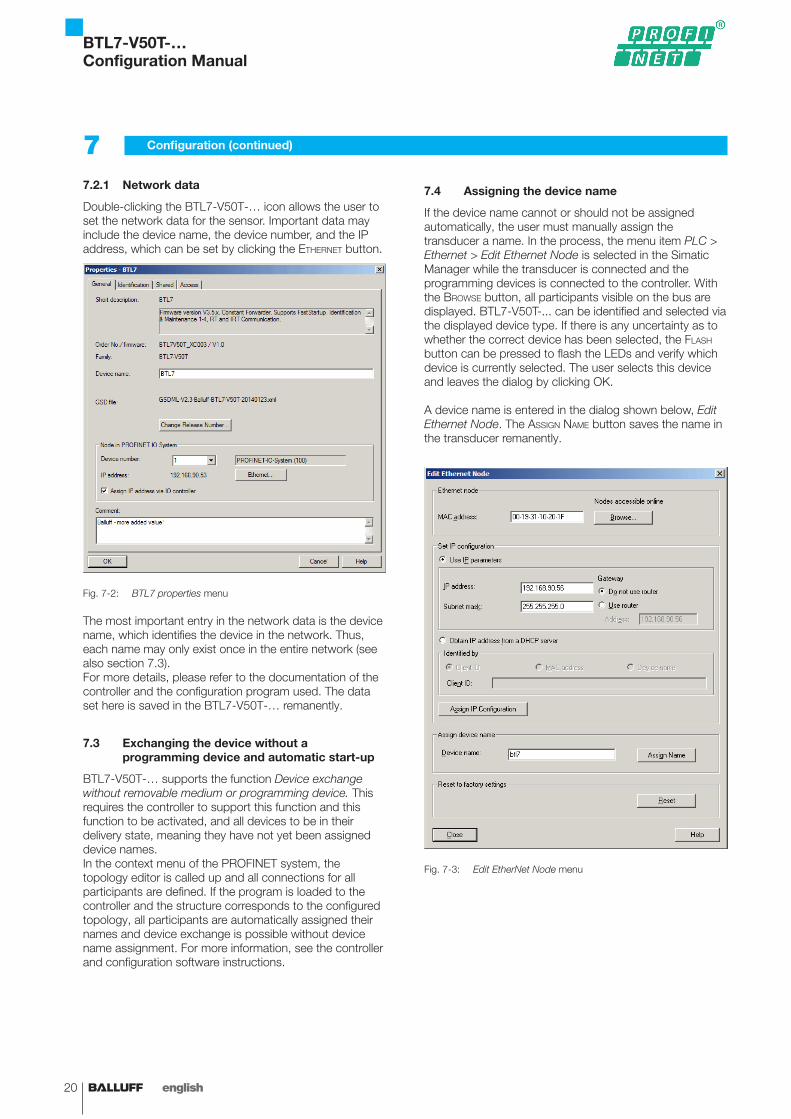
7.2.1 Network data
Double-clicking the BTL7-V50T-… icon allows the user to set the network data for the sensor. Important data may include the device name, the device number, and the IP address, which can be set by clicking the ethernet button.
Fig. 7-2: BTL7 properties menu
The most important entry in the network data is the device name, which identifies the device in the network. Thus, each name may only exist once in the entire network (see also section 7.3).For more details, please refer to the documentation of the controller and the configuration program used. The data set here is saved in the BTL7-V50T-… remanently.
7.3 Exchanging the device without a programming device and automatic start-up
BTL7-V50T-… supports the function Device exchange without removable medium or programming device. This requires the controller to support this function and this function to be activated, and all devices to be in their delivery state, meaning they have not yet been assigned device names.In the context menu of the PROFINET system, the topology editor is called up and all connections for all participants are defined. If the program is loaded to the controller and the structure corresponds to the configured topology, all participants are automatically assigned their names and device exchange is possible without device name assignment. For more information, see the controller and configuration software instructions.
7.4 Assigning the device name
If the device name cannot or should not be assigned automatically, the user must manually assign the transducer a name. In the process, the menu item PLC > Ethernet > Edit Ethernet Node is selected in the Simatic Manager while the transducer is connected and the programming devices is connected to the controller. With the Browse button, all participants visible on the bus are displayed. BTL7-V50T-... can be identified and selected via the displayed device type. If there is any uncertainty as to whether the correct device has been selected, the Flash button can be pressed to flash the LEDs and verify which device is currently selected. The user selects this device and leaves the dialog by clicking OK.
A device name is entered in the dialog shown below, Edit Ethernet Node. The assIgn name button saves the name in the transducer remanently.
Fig. 7-3: Edit EtherNet Node menu
BTL7-V50T-…Configuration Manual
www.balluff.com 21english
7 Configuration (continued)
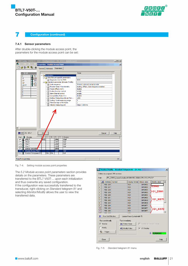
7.4.1 Sensor parameters
After double-clicking the module access point, the parameters for the module access point can be set:
Fig. 7-4: Setting module access point properties
The 5.2 Module access point parameters section provides details on the parameters. These parameters are transferred to the BTL7-V50T-... upon each initialization and thus overwrite any saved configuration.If the configuration was successfully transferred to the transducer, right-clicking on Standard telegram 81 and selecting Monitor/Modify allows the user to view the transferred data.
Fig. 7-5: Standard telegram 81 menu
BTL7-V50T-…Configuration Manual
22 english
7 Configuration (continued)
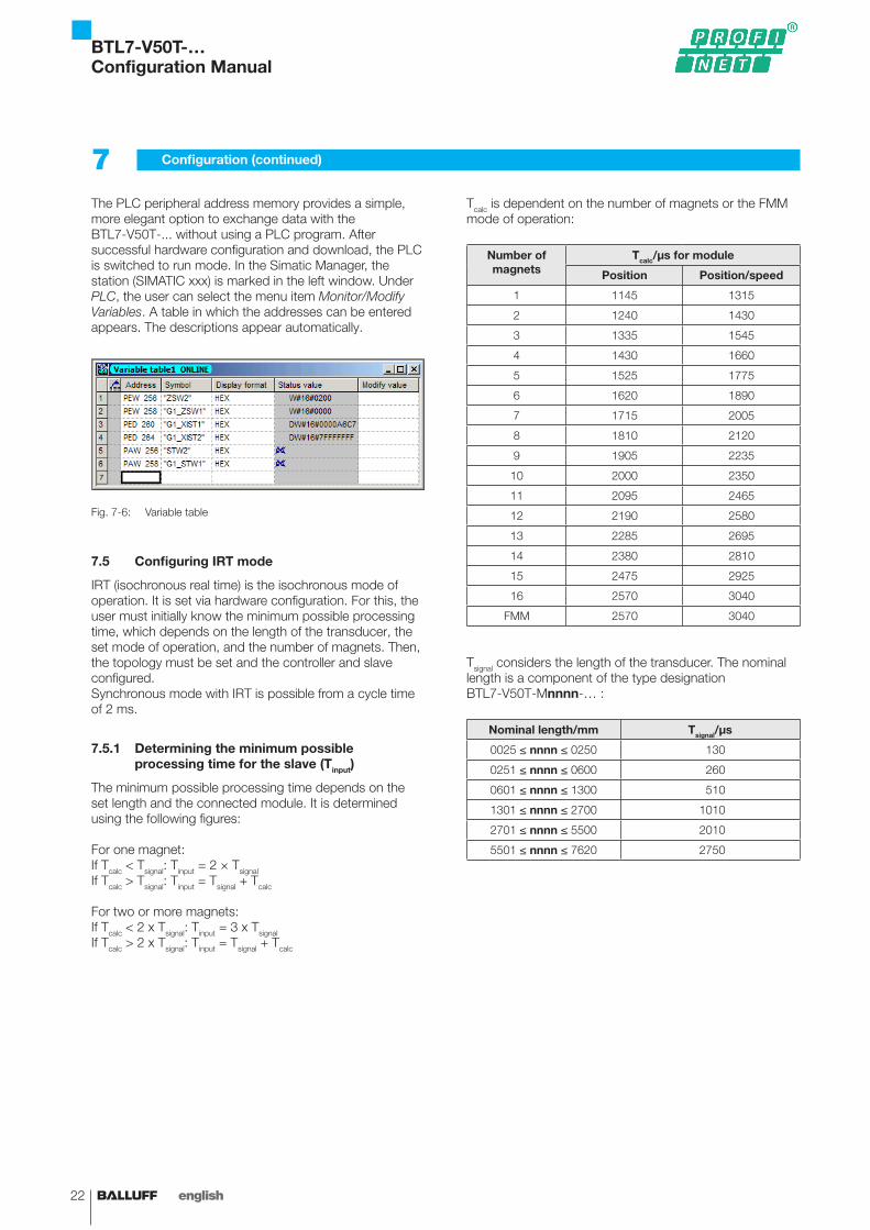
The PLC peripheral address memory provides a simple, more elegant option to exchange data with the BTL7-V50T-... without using a PLC program. After successful hardware configuration and download, the PLC is switched to run mode. In the Simatic Manager, the station (SIMATIC xxx) is marked in the left window. Under PLC, the user can select the menu item Monitor/Modify Variables. A table in which the addresses can be entered appears. The descriptions appear automatically.
Fig. 7-6: Variable table
7.5 Configuring IRT mode
IRT (isochronous real time) is the isochronous mode of operation. It is set via hardware configuration. For this, the user must initially know the minimum possible processing time, which depends on the length of the transducer, the set mode of operation, and the number of magnets. Then, the topology must be set and the controller and slave configured.Synchronous mode with IRT is possible from a cycle time of 2 ms.
7.5.1 Determining the minimum possible processing time for the slave (Tinput)
The minimum possible processing time depends on the set length and the connected module. It is determined using the following figures:
For one magnet:If Tcalc < Tsignal: Tinput = 2 × TsignalIf Tcalc > Tsignal: Tinput = Tsignal + Tcalc
For two or more magnets:If Tcalc < 2 x Tsignal: Tinput = 3 x TsignalIf Tcalc > 2 x Tsignal: Tinput = Tsignal + Tcalc
Tcalc is dependent on the number of magnets or the FMM mode of operation:
Number of magnets
Tcalc/μs for module
Position Position/speed
1 1145 1315
2 1240 1430
3 1335 1545
4 1430 1660
5 1525 1775
6 1620 1890
7 1715 2005
8 1810 2120
9 1905 2235
10 2000 2350
11 2095 2465
12 2190 2580
13 2285 2695
14 2380 2810
15 2475 2925
16 2570 3040
FMM 2570 3040
Tsignal considers the length of the transducer. The nominal length is a component of the type designation BTL7-V50T-Mnnnn-… :
Nominal length/mm Tsignal/μs
0025 ≤ nnnn ≤ 0250 130
0251 ≤ nnnn ≤ 0600 260
0601 ≤ nnnn ≤ 1300 510
1301 ≤ nnnn ≤ 2700 1010
2701 ≤ nnnn ≤ 5500 2010
5501 ≤ nnnn ≤ 7620 2750
BTL7-V50T-…Configuration Manual
www.balluff.com 23english
7 Configuration (continued)
Examples:
BTL7-V50T-M0500-P-C003, inserted module, standard telegram 81Standard telegram 81 requires the same processing time as module 1 Position value– Tcalc from table: 1145 μs– Nominal length 500 mm, resulting in: Tsignal = 260 μs– Tcalc > Tsignal:
Tinput = Tcalc + Tsignal = 1145 μs + 260 μs = 1405 μs
BTL7-V50T-M3000-P-C003, inserted module, 4 position/speed values– Tcalc from table: 1660 μs– Nominal length 3000 mm, resulting in: Tsignal = 2010 μs– Tcalc < 2 × Tsignal:
Tinput = 3 × Tsignal = 2010 μs × 3 = 6030 μs
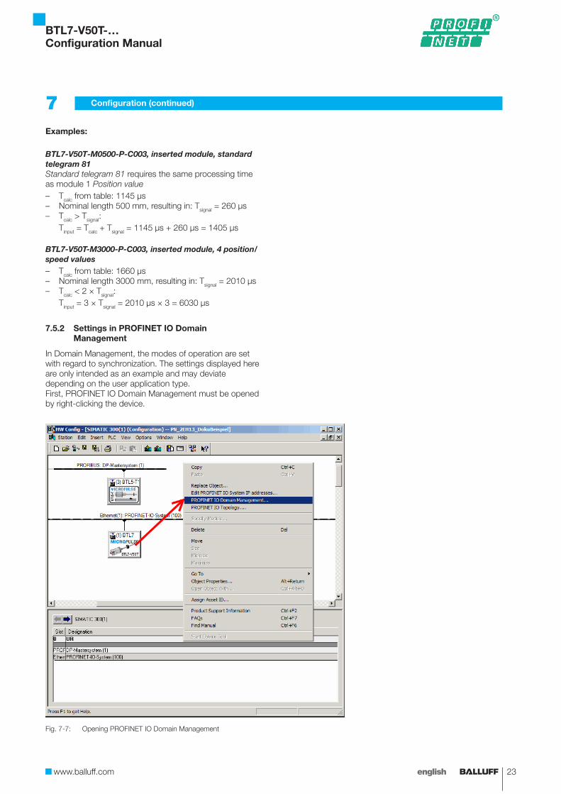
7.5.2 Settings in PROFINET IO Domain Management
In Domain Management, the modes of operation are set with regard to synchronization. The settings displayed here are only intended as an example and may deviate depending on the user application type.First, PROFINET IO Domain Management must be opened by right-clicking the device.
Fig. 7-7: Opening PROFINET IO Domain Management
BTL7-V50T-…Configuration Manual

24 english
There, the mode Sync Master is set for the controller and Sync Slave for the sensor.
Fig. 7-8: Setting sync master and slave
7.5.3 Setting the topology
For IRT, the controller must be familiar with the topology, that is the physical structure of the field bus. The topology settings are reached by right-clicking the device.
Fig. 7-9: Topology Editor
In the Topology Editor, the user can map and check the bus participant connections in the different views.
7 Configuration (continued)
BTL7-V50T-…Configuration Manual
www.balluff.com 25english
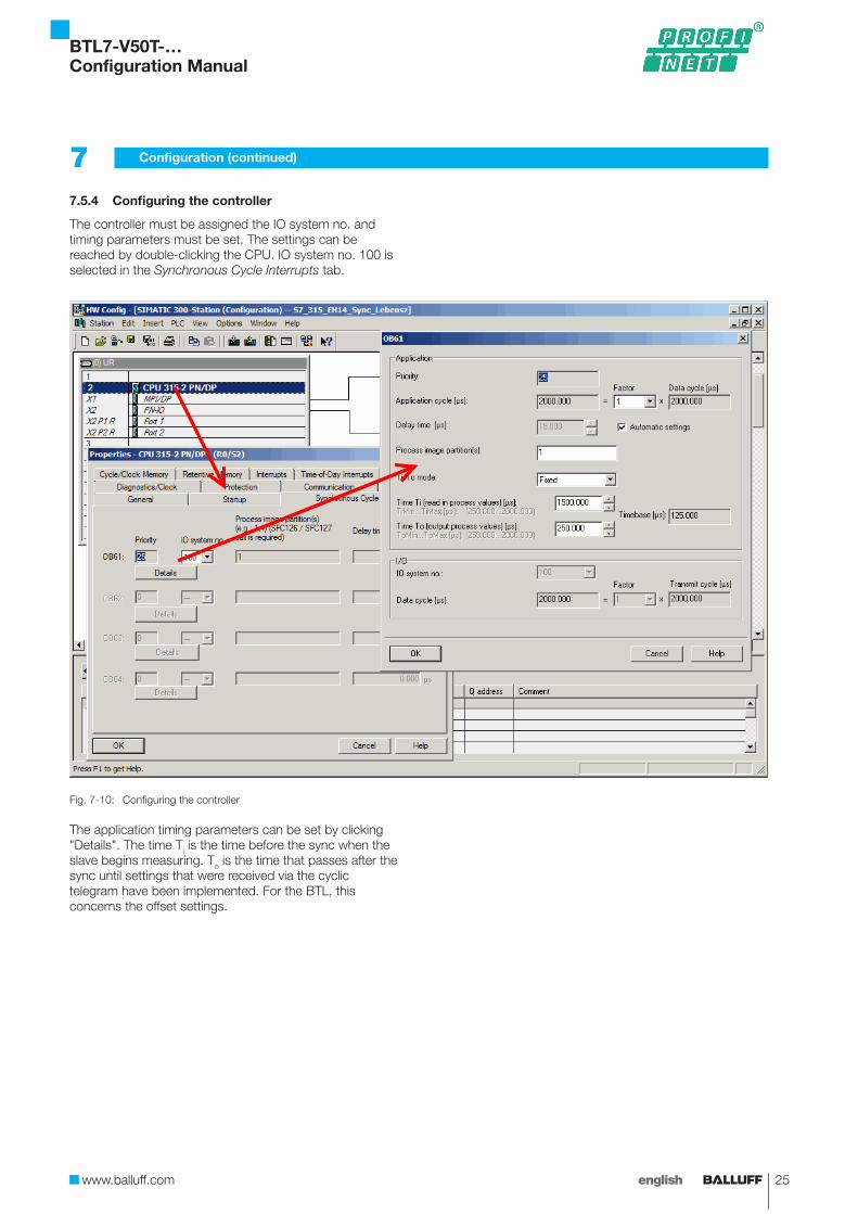
7.5.4 Configuring the controller
The controller must be assigned the IO system no. and timing parameters must be set. The settings can be reached by double-clicking the CPU. IO system no. 100 is selected in the Synchronous Cycle Interrupts tab.
Fig. 7-10: Configuring the controller
The application timing parameters can be set by clicking "Details". The time Ti is the time before the sync when the slave begins measuring. To is the time that passes after the sync until settings that were received via the cyclic telegram have been implemented. For the BTL, this concerns the offset settings.
7 Configuration (continued)
BTL7-V50T-…Configuration Manual
26 english
7 Configuration (continued)
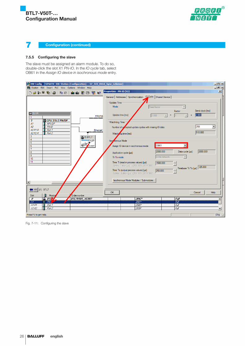
7.5.5 Configuring the slave
The slave must be assigned an alarm module. To do so, double-click the slot X1 PN-IO. In the IO cycle tab, select OB61 in the Assign IO device in isochronous mode entry.
Fig. 7-11: Configuring the slave
BTL7-V50T-…Configuration Manual
www.balluff.com 27english
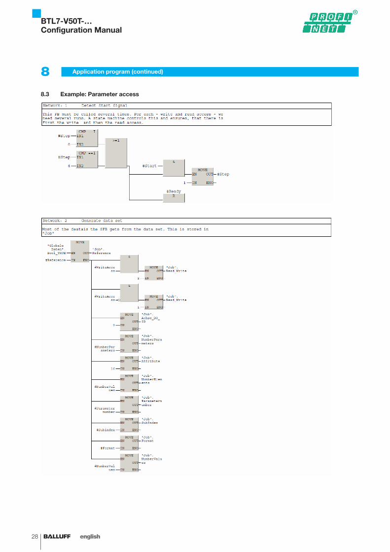
The following excerpts from the Simatic S7 controller provide an example of how to realize main accesses to position data, diagnosis, and parameters. The exact programming must be modified depending on the controller and programming software used. They are only laboratory examples whose functionality has not been verified in a real system.
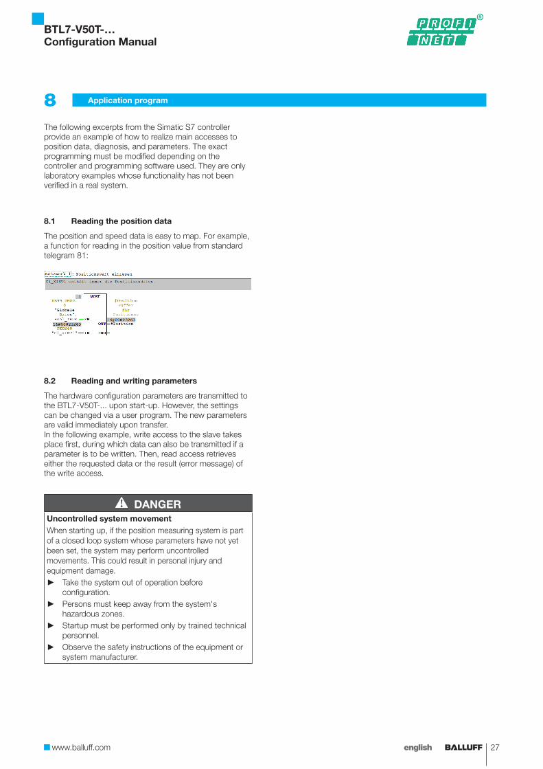
8.1 Reading the position data
The position and speed data is easy to map. For example, a function for reading in the position value from standard telegram 81:
8.2 Reading and writing parameters
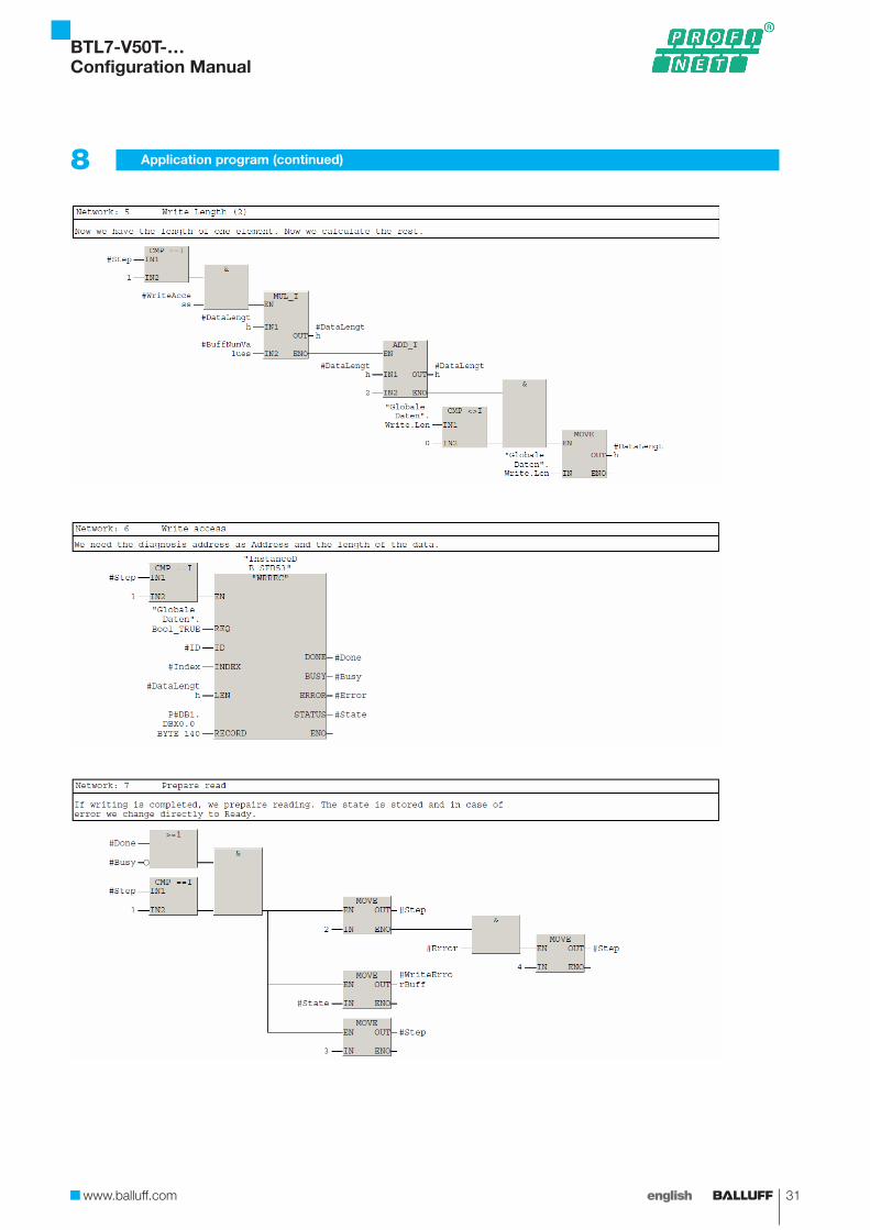
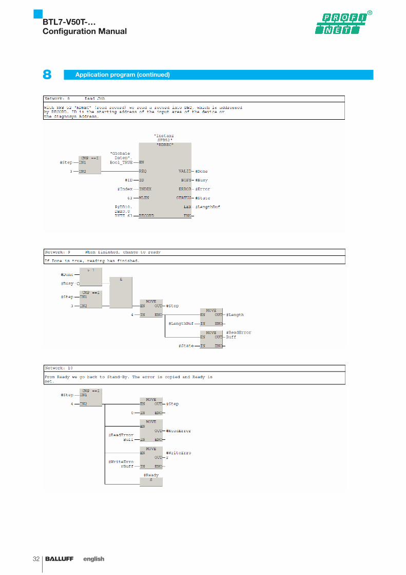
The hardware configuration parameters are transmitted to the BTL7-V50T-... upon start-up. However, the settings can be changed via a user program. The new parameters are valid immediately upon transfer.In the following example, write access to the slave takes place first, during which data can also be transmitted if a parameter is to be written. Then, read access retrieves either the requested data or the result (error message) of the write access.
DANGERUncontrolled system movementWhen starting up, if the position measuring system is part of a closed loop system whose parameters have not yet been set, the system may perform uncontrolled movements. This could result in personal injury and equipment damage.
► Take the system out of operation before configuration.
► Persons must keep away from the system's hazardous zones.
► Startup must be performed only by trained technical personnel.
► Observe the safety instructions of the equipment or system manufacturer.
8 Application program
BTL7-V50T-…Configuration Manual
28 english
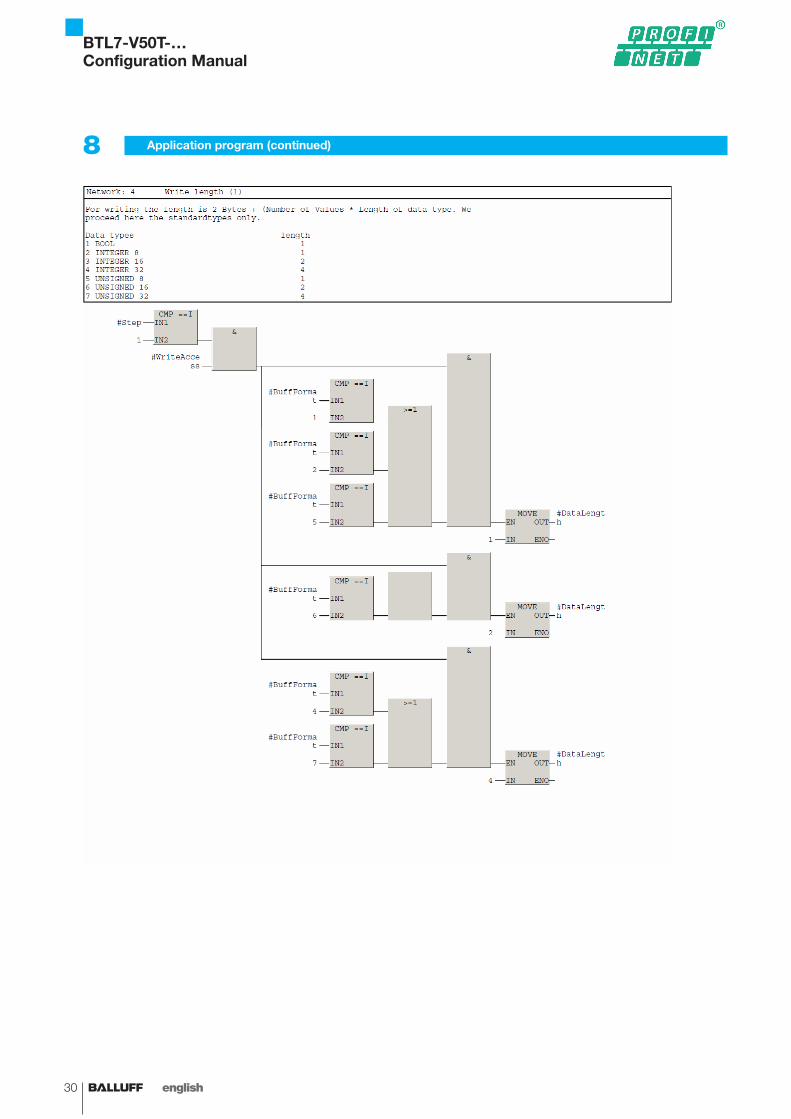
8.3 Example: Parameter access
8 Application program (continued)
BTL7-V50T-…Configuration Manual

www.balluff.com 29english
8 Application program (continued)
BTL7-V50T-…Configuration Manual
30 english
8 Application program (continued)
BTL7-V50T-…Configuration Manual
www.balluff.com 31english
8 Application program (continued)
BTL7-V50T-…Configuration Manual
32 english
8 Application program (continued)
BTL7-V50T-…Configuration Manual
www.balluff.com 33english
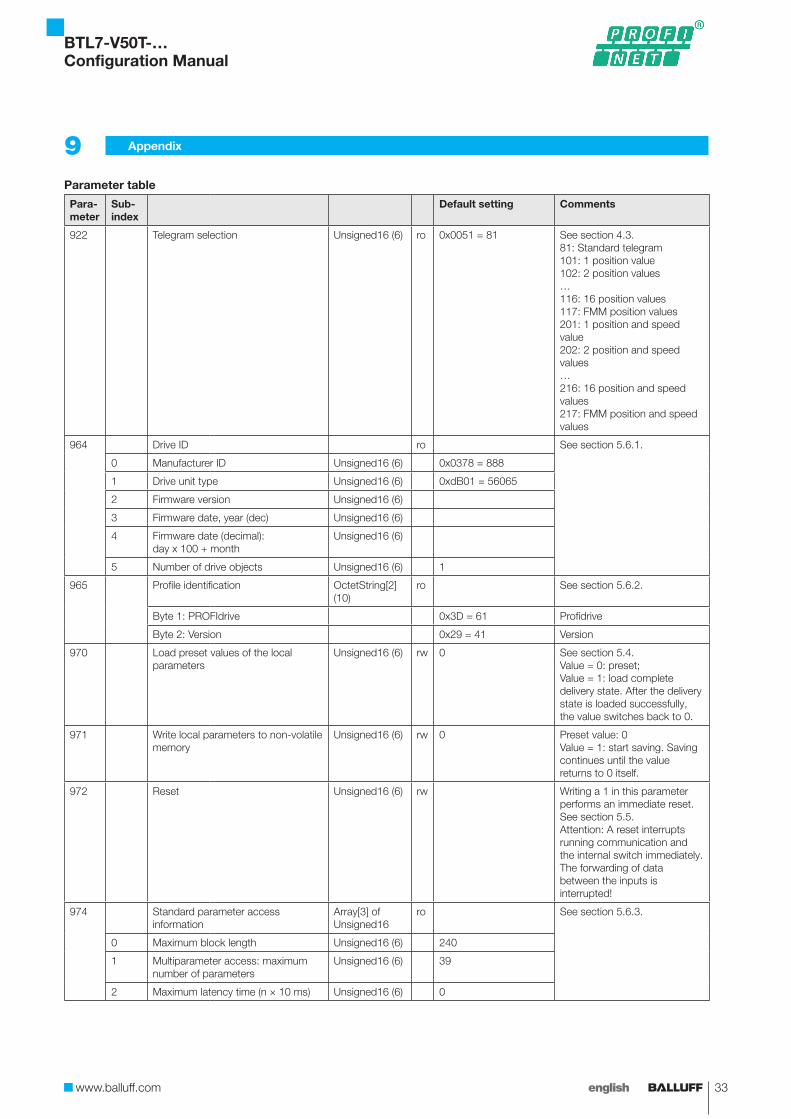
Parameter table
Para-meter
Sub-index
Default setting Comments
922 Telegram selection Unsigned16 (6) ro 0x0051 = 81 See section 4.3.81: Standard telegram101: 1 position value102: 2 position values…116: 16 position values117: FMM position values201: 1 position and speed value202: 2 position and speed values…216: 16 position and speed values217: FMM position and speed values
964 Drive ID ro See section 5.6.1.
0 Manufacturer ID Unsigned16 (6) 0x0378 = 888
1 Drive unit type Unsigned16 (6) 0xdB01 = 56065
2 Firmware version Unsigned16 (6)
3 Firmware date, year (dec) Unsigned16 (6)
4 Firmware date (decimal): day x 100 + month
Unsigned16 (6)
5 Number of drive objects Unsigned16 (6) 1
965 Profile identification OctetString[2] (10)
ro See section 5.6.2.
Byte 1: PROFIdrive 0x3D = 61 Profidrive
Byte 2: Version 0x29 = 41 Version
970 Load preset values of the local parameters
Unsigned16 (6) rw 0 See section 5.4.Value = 0: preset;Value = 1: load complete delivery state. After the delivery state is loaded successfully, the value switches back to 0.
971 Write local parameters to non-volatile memory
Unsigned16 (6) rw 0 Preset value: 0Value = 1: start saving. Saving continues until the value returns to 0 itself.
972 Reset Unsigned16 (6) rw Writing a 1 in this parameter performs an immediate reset. See section 5.5.Attention: A reset interrupts running communication and the internal switch immediately. The forwarding of data between the inputs is interrupted!
974 Standard parameter access information
Array[3] of Unsigned16
ro See section 5.6.3.
0 Maximum block length Unsigned16 (6) 240
1 Multiparameter access: maximum number of parameters
Unsigned16 (6) 39
2 Maximum latency time (n × 10 ms) Unsigned16 (6) 0
9 Appendix
BTL7-V50T-…Configuration Manual
34 english
Para-meter
Sub-index
Default setting Comments
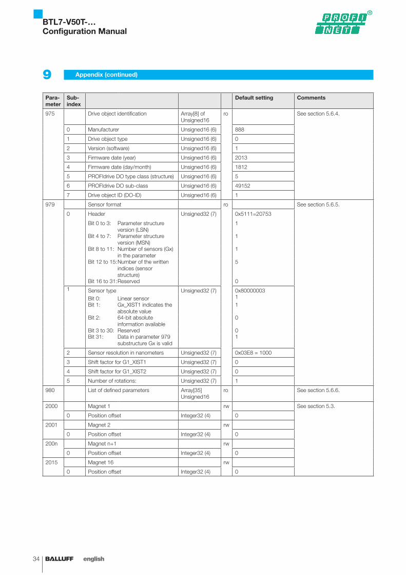
975 Drive object identification Array[8] of Unsigned16
ro See section 5.6.4.
0 Manufacturer Unsigned16 (6) 888
1 Drive object type Unsigned16 (6) 0
2 Version (software) Unsigned16 (6) 1
3 Firmware date (year) Unsigned16 (6) 2013
4 Firmware date (day/month) Unsigned16 (6) 1812
5 PROFIdrive DO type class (structure) Unsigned16 (6) 5
6 PROFIdrive DO sub-class Unsigned16 (6) 49152
7 Drive object ID (DO-ID) Unsigned16 (6) 1
979 Sensor format ro See section 5.6.5.
0 Header Unsigned32 (7) 0x5111=20753
Bit 0 to 3: Parameter structure version (LSN)
1
Bit 4 to 7: Parameter structure version (MSN)
1
Bit 8 to 11: Number of sensors (Gx) in the parameter
1
Bit 12 to 15: Number of the written indices (sensor structure)
5
Bit 16 to 31: Reserved 01 Sensor type Unsigned32 (7) 0x80000003
Bit 0: Linear sensor 1Bit 1: Gx_XIST1 indicates the
absolute value1
Bit 2: 64-bit absolute information available
0
Bit 3 to 30: Reserved 0Bit 31: Data in parameter 979
substructure Gx is valid1
2 Sensor resolution in nanometers Unsigned32 (7) 0x03E8 = 1000
3 Shift factor for G1_XIST1 Unsigned32 (7) 0
4 Shift factor for G1_XIST2 Unsigned32 (7) 0
5 Number of rotations: Unsigned32 (7) 1
980 List of defined parameters Array[35] Unsigned16
ro See section 5.6.6.
2000 Magnet 1 rw See section 5.3.
0 Position offset Integer32 (4) 0
2001 Magnet 2 rw
0 Position offset Integer32 (4) 0
200n Magnet n+1 rw
0 Position offset Integer32 (4) 0
2015 Magnet 16 rw
0 Position offset Integer32 (4) 0
9 Appendix (continued)
BTL7-V50T-…Configuration Manual
www.balluff.com 35english
Para-meter
Sub-index
Default setting Comments
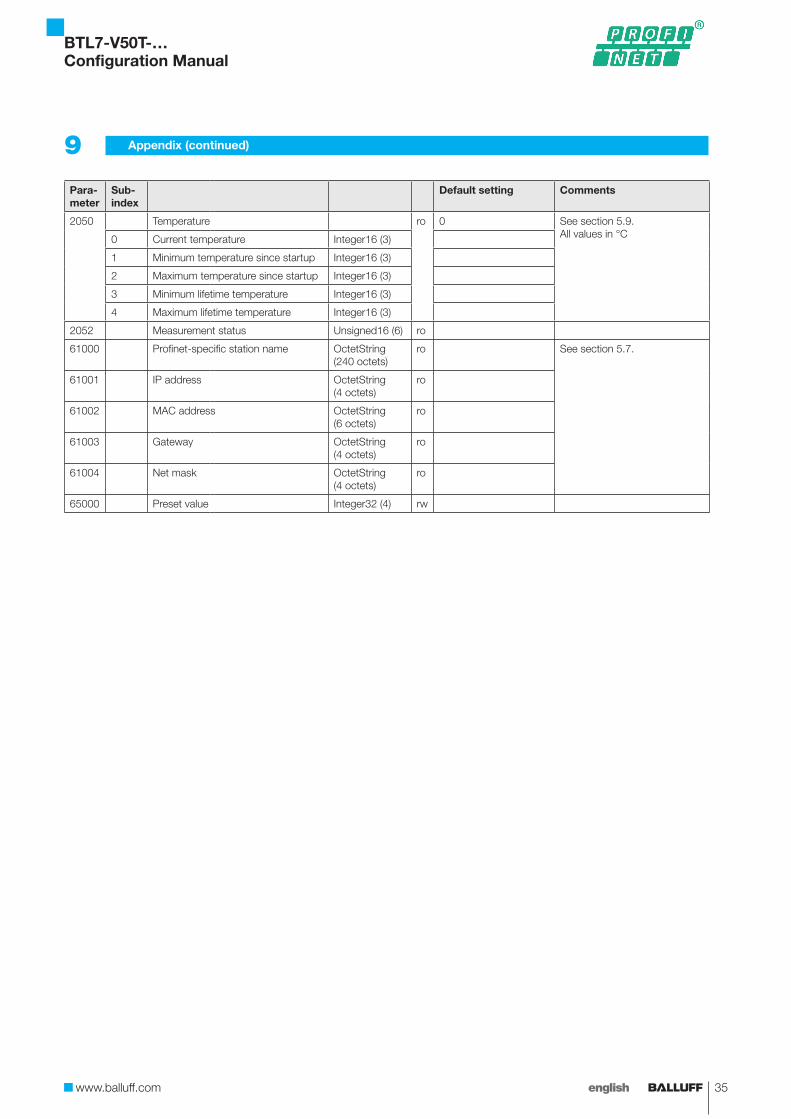
2050 Temperature ro 0 See section 5.9.All values in °C0 Current temperature Integer16 (3)
1 Minimum temperature since startup Integer16 (3)
2 Maximum temperature since startup Integer16 (3)
3 Minimum lifetime temperature Integer16 (3)
4 Maximum lifetime temperature Integer16 (3)
2052 Measurement status Unsigned16 (6) ro
61000 Profinet-specific station name OctetString (240 octets)
ro See section 5.7.
61001 IP address OctetString (4 octets)
ro
61002 MAC address OctetString (6 octets)
ro
61003 Gateway OctetString (4 octets)
ro
61004 Net mask OctetString (4 octets)
ro
65000 Preset value Integer32 (4) rw
9 Appendix (continued)
BTL7-V50T-…Configuration Manual
36 english
9 Appendix (continued)
Para-meter
Sub-index
Default setting Comments
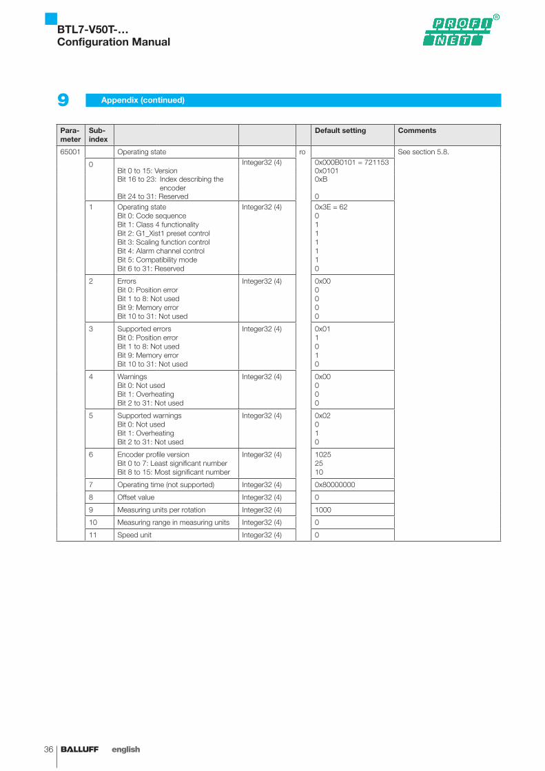
65001 Operating state ro See section 5.8.
0 Integer32 (4) 0x000B0101 = 721153Bit 0 to 15: Version 0x0101Bit 16 to 23: Index describing the
encoder0xB
Bit 24 to 31: Reserved 01 Operating state
Bit 0: Code sequenceBit 1: Class 4 functionalityBit 2: G1_Xist1 preset controlBit 3: Scaling function controlBit 4: Alarm channel controlBit 5: Compatibility modeBit 6 to 31: Reserved
Integer32 (4) 0x3E = 620111110
2 ErrorsBit 0: Position errorBit 1 to 8: Not usedBit 9: Memory errorBit 10 to 31: Not used
Integer32 (4) 0x000000
3 Supported errorsBit 0: Position errorBit 1 to 8: Not usedBit 9: Memory errorBit 10 to 31: Not used
Integer32 (4) 0x011010
4 WarningsBit 0: Not usedBit 1: OverheatingBit 2 to 31: Not used
Integer32 (4) 0x00000
5 Supported warningsBit 0: Not usedBit 1: OverheatingBit 2 to 31: Not used
Integer32 (4) 0x02010
6 Encoder profile versionBit 0 to 7: Least significant numberBit 8 to 15: Most significant number
Integer32 (4) 10252510
7 Operating time (not supported) Integer32 (4) 0x80000000
8 Offset value Integer32 (4) 0
9 Measuring units per rotation Integer32 (4) 1000
10 Measuring range in measuring units Integer32 (4) 0
11 Speed unit Integer32 (4) 0
BTL7-V50T-…Configuration Manual

Headquarters GermanyBalluff GmbHSchurwaldstrasse 973765 Neuhausen a.d.F.Phone + 49 7158 173-0Fax +49 7158 [email protected]
Global Service Center
GermanyBalluff GmbHSchurwaldstrasse 973765 Neuhausen a.d.F.Phone +49 7158 173-370Fax +49 7158 [email protected]
US Service Center
USABalluff Inc.8125 Holton DriveFlorence, KY 41042Phone (859) 727-2200Toll-free 1-800-543-8390Fax (859) 727-4823 [email protected]
CN Service Center
ChinaBalluff (Shanghai) trading Co., ltd.Room 1006, Pujian Rd. 145. Shanghai, 200127, P.R. China Phone +86 (21) 5089 9970Fax +86 (21) 5089 [email protected]
www.balluff.com
No.
913
507-
726
EN
· 00
.000
000
· E14
; Sub
ject
to m
odifi
catio
n.